stretch wrapping machine l2500 auto 1 - … auto1 eng.pdf · manual and ce-instructions march 2001...
TRANSCRIPT
Manual andCE-instructions
MARCH 2001
STRETCH WRAPPINGMACHINE L2500 AUTO 1
STRETCH WRAPPINGMACHINE L2500 AUTO 1
Nissen L2500 Auto 1 2
Index
1 Nissen Stretch Wrapping Machines .................................31.1 Machine type: NISSEN L2500 AUTO 1..................................3
1.2 Technical specification ...........................................................4
1.3 Areas of use ...........................................................................5
1.4 Guarantee ..............................................................................5
1.5 Limits of responsibility ............................................................6
1.6 Machine plate .........................................................................6
2. Assembly instructions ......................................................72.1 Installing the machine ............................................................8
3. Dismantling ......................................................................203.1 Dismantling ..........................................................................20
3.2 Disposing of the machine .....................................................20
4. Instructions for use .........................................................214.1 General ................................................................................21
4.2 The control panel .................................................................21
4.3 Operation .............................................................................22
4.4 Adjustments on operator’s panel .........................................22
4.5 Plastic film ............................................................................24
4.6 Adjustment of stop position of turntable rotation..................25
5. Safety regulations ............................................................265.1 Area of risk...........................................................................26
5.2 Other safety instructions ......................................................27
6. Maintenance .....................................................................286.1 Cleaning of the pre-stretching unit .......................................28
6.2 Care of the drive unit ............................................................28
6.3 Care of the turntable ............................................................29
6.4 Other maintenance instructions ...........................................29
Nissen L2500 Auto 1 3
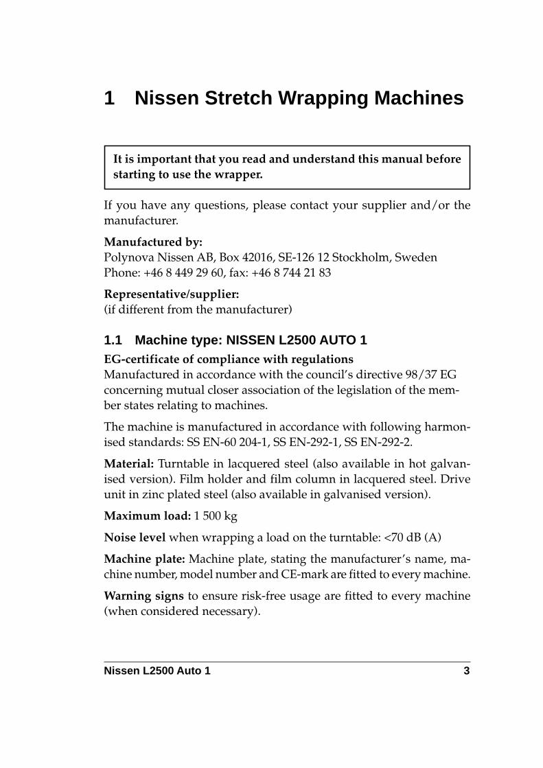
1 Nissen Stretch Wrapping Machines
It is important that you read and understand this manual beforestarting to use the wrapper.
If you have any questions, please contact your supplier and/or themanufacturer.
Manufactured by:Polynova Nissen AB, Box 42016, SE-126 12 Stockholm, SwedenPhone: +46 8 449 29 60, fax: +46 8 744 21 83
Representative/supplier:(if different from the manufacturer)
1.1 Machine type: NISSEN L2500 AUTO 1EG-certificate of compliance with regulationsManufactured in accordance with the council’s directive 98/37 EGconcerning mutual closer association of the legislation of the mem-ber states relating to machines.
The machine is manufactured in accordance with following harmon-ised standards: SS EN-60 204-1, SS EN-292-1, SS EN-292-2.
Material: Turntable in lacquered steel (also available in hot galvan-ised version). Film holder and film column in lacquered steel. Driveunit in zinc plated steel (also available in galvanised version).
Maximum load: 1 500 kg
Noise level when wrapping a load on the turntable: <70 dB (A)
Machine plate: Machine plate, stating the manufacturer’s name, ma-chine number, model number and CE-mark are fitted to every machine.
Warning signs to ensure risk-free usage are fitted to every machine(when considered necessary).
Nissen L2500 Auto 1 4
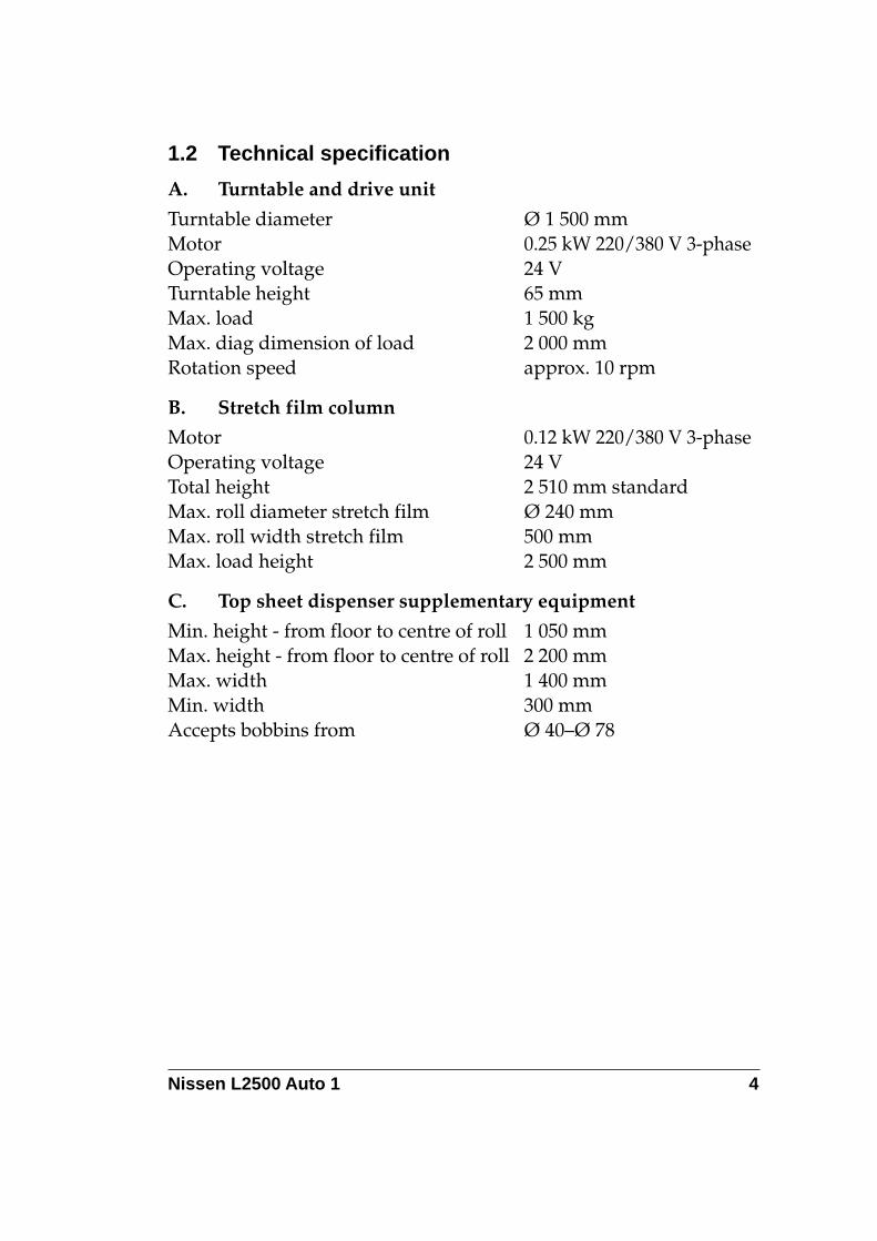
1.2 Technical specification
A. Turntable and drive unit
Turntable diameter Ø 1 500 mmMotor 0.25 kW 220/380 V 3-phaseOperating voltage 24 VTurntable height 65 mmMax. load 1 500 kgMax. diag dimension of load 2 000 mmRotation speed approx. 10 rpm
B. Stretch film column
Motor 0.12 kW 220/380 V 3-phaseOperating voltage 24 VTotal height 2 510 mm standardMax. roll diameter stretch film Ø 240 mmMax. roll width stretch film 500 mmMax. load height 2 500 mm
C. Top sheet dispenser supplementary equipment
Min. height - from floor to centre of roll 1 050 mmMax. height - from floor to centre of roll 2 200 mmMax. width 1 400 mmMin. width 300 mmAccepts bobbins from Ø 40–Ø 78
Nissen L2500 Auto 1 5
1.3 Areas of useThis machine is normally used in warehouses and/or distributioncentres for wrapping loaded pallets in stretch film in order to main-tain stability, provide protection from the elements and protect the loadduring storage or distribution.
The loaded pallet is positioned on the turntable of the machine with apallet truck or fork-lift. The stretch film is attached manually by, e.g.the film being tied to the pallet.
Wrapping is carried out by rotating the load whilst the film roll movesup and down the film column. Some machines are fitted with a topclamp plate, which holds light loads in place whilst the wrapping oper-ation takes place.
Neither the operator nor any other person is allowed to standon the turntable. If the turntable has to be stepped on (duringservice or repairs), switch off the main power supply or pressthe emergency stop button.
1.4 GuaranteeThe guarantee is valid for one (1) year from the date of delivery, andcovers material and manufacturing faults. Maintenance must have beencarried out according to the instructions on pages 28–29 for the guar-antee to be valid.
This guarantee does not cover normal maintenance, installation or regu-lar adjustment in accordance with the instructions. Nor does the guar-antee cover labour costs involved in such work.
Damage caused by misuse or faulty usage will result in the guaranteeno longer being valid. If the machine is to be located in a damp envir-onment the turntable, film column and drive units should be galvan-ised for the guarantee to be valid.
The guarantee is valid as long as the machine is not altered or addedto without the manufacturer’s written approval.
Nissen L2500 Auto 1 6
1.5 Limits of responsibilityThe supplier accepts responsibility only for the machine and its oper-ation in accordance with the manual, on conditions that the machine isnot altered or added to without the manufacturer’s written approval.
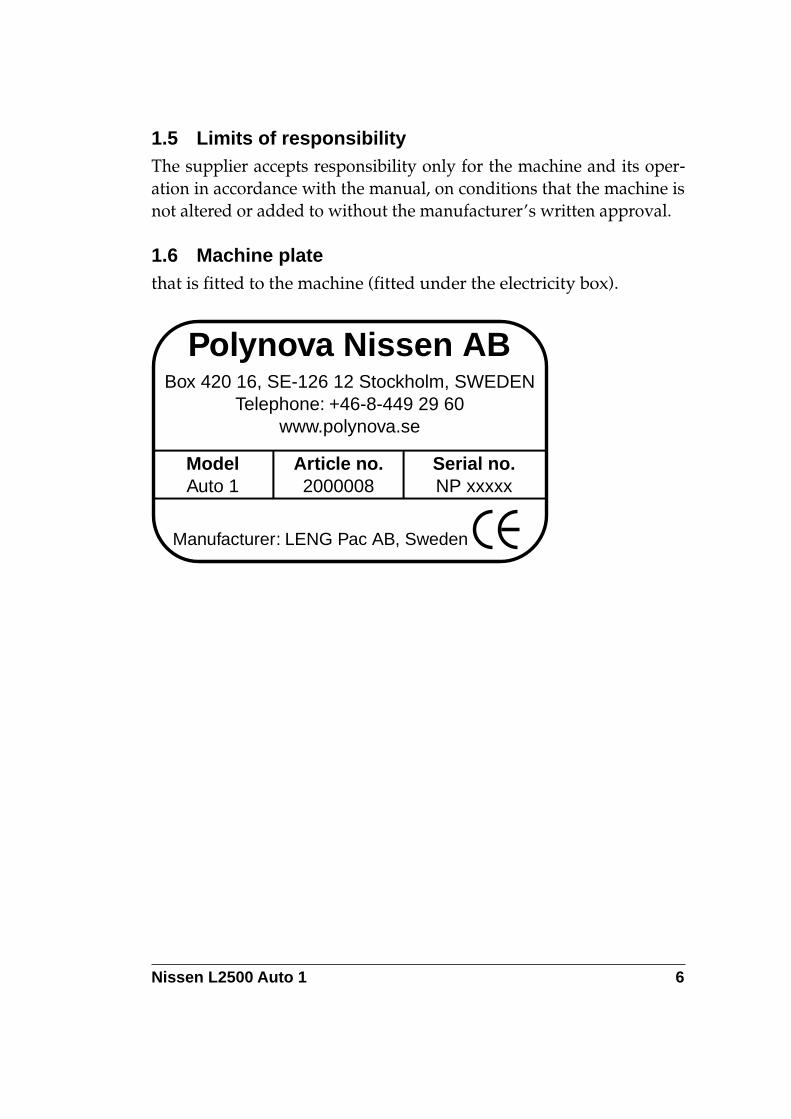
1.6 Machine platethat is fitted to the machine (fitted under the electricity box).
Polynova Nissen ABBox 420 16, SE-126 12 Stockholm, SWEDEN
Telephone: +46-8-449 29 60www.polynova.se
ModelAuto 1
Article no.2000008
Serial no.NP xxxxx
Manufacturer: LENG Pac AB, Sweden
Nissen L2500 Auto 1 7
2. Assembly instructions
Begin by first reading through the entire assembly instructions.
Make sure that the following items are available before assembly:
1. Hammer drill2. 10 mm hammer bit3. Spanners4. Allen keys5. Socket spanners6. Screwdriver7. Cable cutters and strippers8. Vacuum cleaner (for cement dust)9. Hammer10. Cable clip pliers
Nissen L2500 Auto 1 8
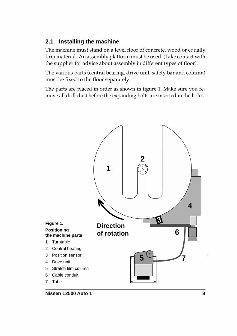
2.1 Installing the machineThe machine must stand on a level floor of concrete, wood or equallyfirm material. An assembly platform must be used. (Take contact withthe supplier for advice about assembly in different types of floor).
The various parts (central bearing, drive unit, safety bar and column)must be fixed to the floor separately.
The parts are placed in order as shown in figure 1. Make sure you re-move all drill-dust before the expanding bolts are inserted in the holes.
21
4
5
6Directionof rotation
7
3Figure 1.
Positioningthe machine parts
1 Turntable
2 Central bearing
3 Position sensor
4 Drive unit
5 Stretch film column
6 Cable conduit
7 Tube
Nissen L2500 Auto 1 9
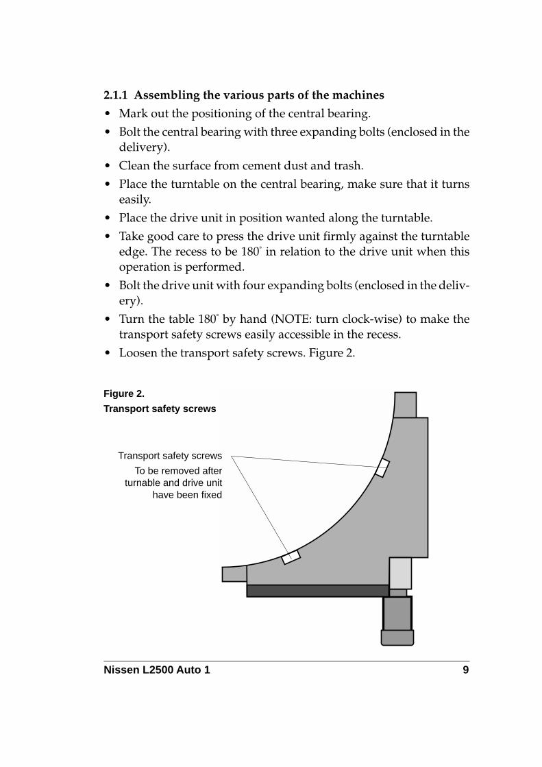
2.1.1 Assembling the various parts of the machines
• Mark out the positioning of the central bearing.
• Bolt the central bearing with three expanding bolts (enclosed in thedelivery).
• Clean the surface from cement dust and trash.
• Place the turntable on the central bearing, make sure that it turnseasily.
• Place the drive unit in position wanted along the turntable.
• Take good care to press the drive unit firmly against the turntableedge. The recess to be 180° in relation to the drive unit when thisoperation is performed.
• Bolt the drive unit with four expanding bolts (enclosed in the deliv-ery).
• Turn the table 180° by hand (NOTE: turn clock-wise) to make thetransport safety screws easily accessible in the recess.
• Loosen the transport safety screws. Figure 2.
Figure 2.
Transport safety screws
Transport safety screws
To be removed afterturnable and drive unit
have been fixed
Nissen L2500 Auto 1 10
2.1.2 Electrical installation
All electrical work must be carried out by an authorised electrician.
• Loosen the cable conduit. Figure 1.
• Insert the cables in the pre-mounted tube (mounted on the cableconduit).
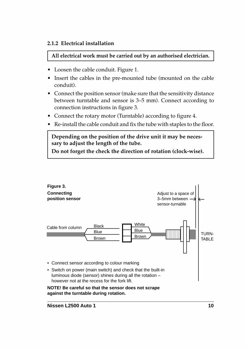
• Connect the position sensor (make sure that the sensitivity distancebetween turntable and sensor is 3–5 mm). Connect according toconnection instructions in figure 3.
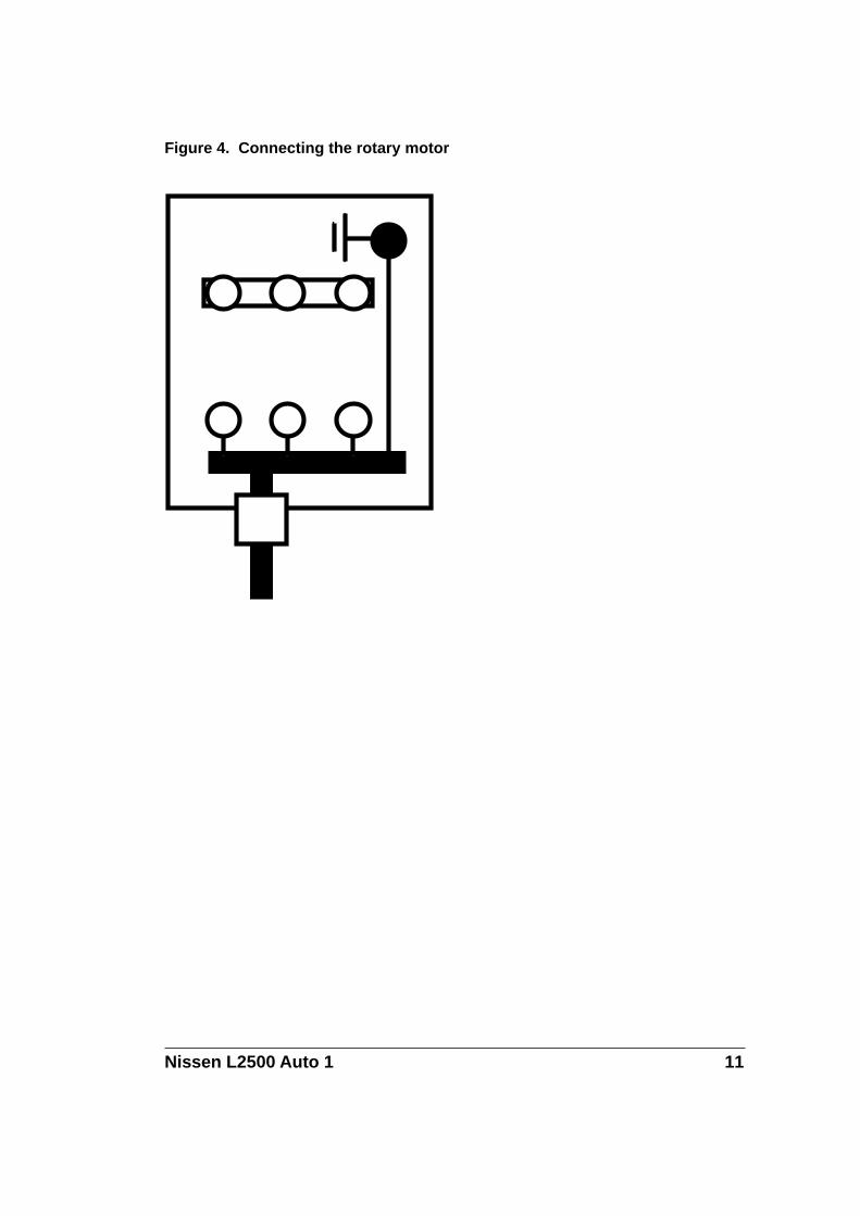
• Connect the rotary motor (Turntable) according to figure 4.
• Re-install the cable conduit and fix the tube with staples to the floor.
Depending on the position of the drive unit it may be neces-sary to adjust the length of the tube.Do not forget the check the direction of rotation (clock-wise).
Cable from column BlackBlue
Brown
WhiteBlueBrown
Adjust to a space of3–5mm betweensensor-turnable
TURN-TABLE
Figure 3.
Connectingposition sensor
• Connect sensor according to colour marking
• Switch on power (main switch) and check that the built-inluminous diode (sensor) shines during all the rotation –however not at the recess for the fork lift.
NOTE! Be careful so that the sensor does not scrapeagainst the turntable during rotation.
Nissen L2500 Auto 1 11
Figure 4. Connecting the rotary motor
Nissen L2500 Auto 1 12
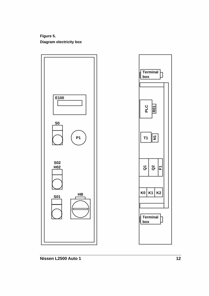
Figure 5.
Diagram electricity box
Terminalbox
PL
C
R01
T1 N1
Q1
Q2
F1
K0 K1 K2
P1
E100
S0
S02H02
S01HB
Terminalbox
Nissen L2500 Auto 1 13
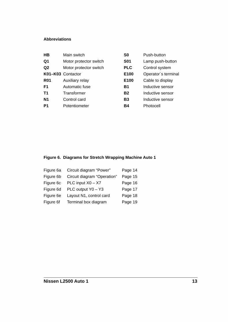
HB Main switch
Q1 Motor protector switch
Q2 Motor protector switch
K01–K03 Contactor
R01 Auxiliary relay
F1 Automatic fuse
T1 Transformer
N1 Control card
P1 Potentiometer
S0 Push-button
S01 Lamp push-button
PLC Control system
E100 Operator´s terminal
E100 Cable to display
B1 Inductive sensor
B2 Inductive sensor
B3 Inductive sensor
B4 Photocell
Abbreviations
Figure 6. Diagrams for Stretch Wrapping Machine Auto 1
Figure 6a Circuit diagram “Power” Page 14
Figure 6b Circuit diagram “Operation” Page 15
Figure 6c PLC input X0 – X7 Page 16
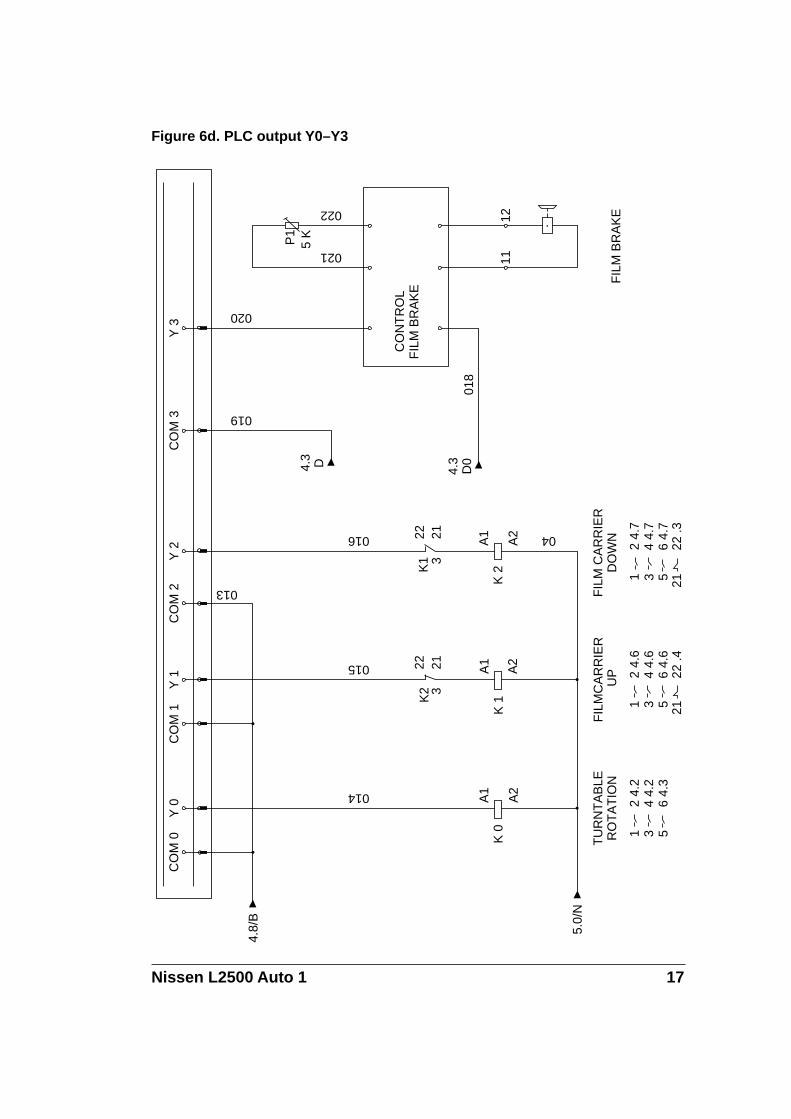
Figure 6d PLC output Y0 – Y3 Page 17
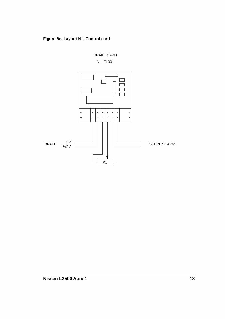
Figure 6e Layout N1, control card Page 18
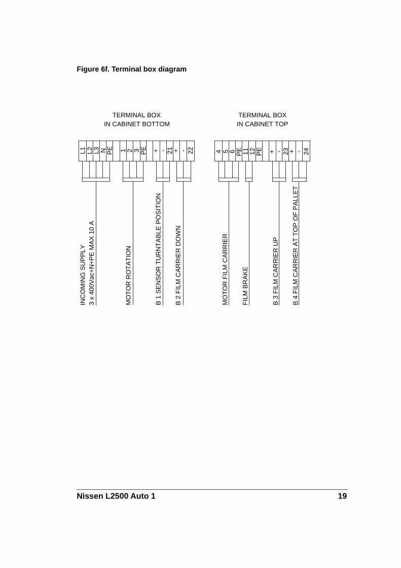
Figure 6f Terminal box diagram Page 19
Nissen L2500 Auto 1 14
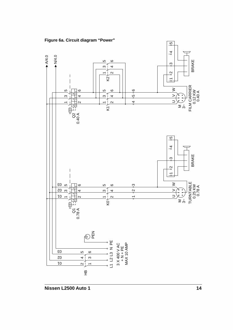
Figure 6a. Circuit diagram “Power”
HB
L1L2
3 X
400
V A
C
+ N
+ P
EM
AX
10
AM
P
L3N
PE
PE
N
M 3~
Q2
1 2
3 4
5 6
K1
4 U
5 V
FIL
M C
AR
RIE
R0.
12 K
W0.
40 A
6 W1K2
2 BR
AK
E
34
5
A/4
.0
N/4
.0
13
5
24
6
13
5
24
6
M 3~
1 2
3 4
5 6
K0
1 U
2 V
TU
RN
TA
BLE
0.25
KW
0.78
A
3 W1
2 BR
AK
E
34
5
13
5
24
6
01
02
03
0.40
AQ
10.
78 A
24
5
13
6
01
02
03
Nissen L2500 Auto 1 15
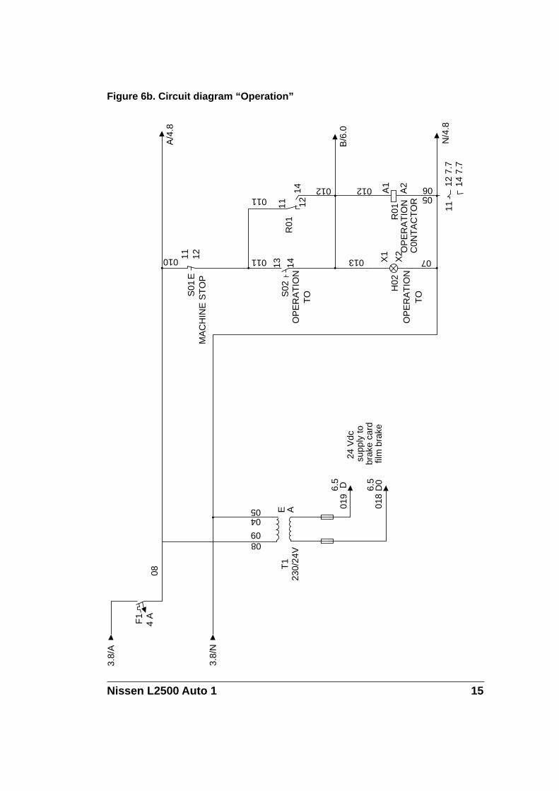
Figure 6b. Circuit diagram “Operation”3.
8/A
4 AF1
08
0809
230/
24V
T1
05 019
018
6.5 D 6.5
D0
24 V
dc
supp
ly to
brak
e ca
rdfil
m b
rake
010
MA
CH
INE
ST
OP
S01
11 12 011
OP
ER
AT
ION
TOS
0213 14 -
013
OP
ER
AT
ION
TO
H02
X1
X2 07
011
R01
11 1214 012 012
1112
7.7
14 7
.7
OP
ER
AT
ION
C0N
TA
CT
OR
R01
A1
A2
0506
3.8/
N
04E A
E
N/4
.8
B/6
.0
A/4
.8
Nissen L2500 Auto 1 16
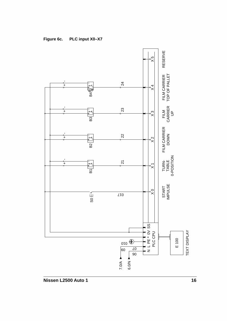
Figure 6c. PLC input X0–X7
06
07
N
09
010
L PLC
CP
U
E 1
00
TE
XT
DIS
PLA
Y
+S
S
S0
017 X 0
ST
AR
TIM
PU
LSE
+
B1
21
X 1
TU
RN
-T
AB
LE0-
PO
SIT
ION-
+
B2
22
X 2
FIL
M C
AR
RIE
RD
OW
N
-+
B3
23
X 3
FIL
M
CA
RR
IER
U
P
-+
B4
24
X 4
FIL
M C
AR
RIE
RT
OP
OF
PA
LLE
T
-
X 5
RE
SE
RV
E
7.0/
A
6.0/
N
PE
0V
++
++
--
--
Nissen L2500 Auto 1 17
Figure 6d. PLC output Y0–Y3
CO
M 0
Y 0
014
K 0
A1
A2
TU
RN
TA
BLE
RO
TA
TIO
N
CO
M 1
Y 1
015
K2 3
22 21
K 1
A1
A2
FIL
MC
AR
RIE
R U
P
CO
M 2 013
Y 2
016
K1 3
22 21
K 2
A1
A2 04
FIL
M C
AR
RIE
RD
OW
N
4.3 D 4.3
D0
CO
M 3 019
018
Y 3
020
CO
NT
RO
LF
ILM
BR
AK
E
021
11
5 KP1
022
12
FIL
M B
RA
KE
4.8/
B
5.0/
N
1 3 5 21
2 4.
74
4.7
6 4.
722
.3
2 4.
64
4.6
6 4.
622
.4
1 3 5 21
1 3 5
2 4.
24
4.2
6 4.
3
Nissen L2500 Auto 1 18
Figure 6e. Layout N1, Control card
BRAKE0V
+24V
BRAKE CARD
NL–EL001
P 1
SUPPLY 24Vac
Nissen L2500 Auto 1 19
Figure 6f. Terminal box diagram
L1 L2 L3 N PE 1 2
TERMINAL BOXIN CABINET BOTTOM
3 PE + - 21 + - 22 4 5 6 PE 11 12 PE
TERMINAL BOXIN CABINET TOP
+ - 23 24+ -
INC
OM
ING
SU
PP
LY3
x 40
0Vac
+N
+P
E M
AX
10
A
MO
TO
R R
OT
AT
ION
B 1
SE
NS
OR
TU
RN
TA
BLE
PO
SIT
ION
B 2
FIL
M C
AR
RIE
R D
OW
N
MO
TO
R F
ILM
CA
RR
IER
FIL
M B
RA
KE
B 3
FIL
M C
AR
RIE
R U
P
B 4
FIL
M C
AR
RIE
R A
T T
OP
OF
PA
LLE
T
Nissen L2500 Auto 1 20
3. Dismantling
3.1 DismantlingIn order to dismantle the machine follow the instructions under point2.1, but in the reverse order.
3.2 Disposing of the machineWhen, after many years service, your machine is finally ready for dis-posal it should be done in a way that is not detrimental to the environ-ment.
NISSEN STRETCH WRAPPING MACHINES are manufactured fromrecyclable and, therefore, environmentally friendly materials.
Nissen L2500 Auto 1 21
4. Instructions for use
4.1 GeneralThe management responsible for the machine shall make sure that theoperator checks to see that there is nobody close to the machine whocould be injured before the machine is started.
A safety area of at least 800 mm from the edge of the turntable mustalways be kept free of people, goods etc.
4.2 The control panel
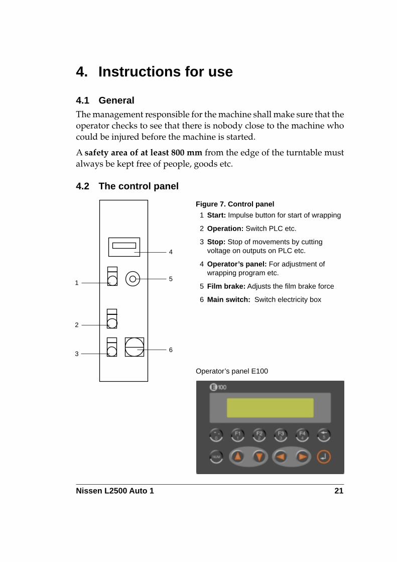
Figure 7. Control panel
1 Start: Impulse button for start of wrapping
2 Operation: Switch PLC etc.
3 Stop: Stop of movements by cuttingvoltage on outputs on PLC etc.
4 Operator’s panel: For adjustment ofwrapping program etc.
5 Film brake: Adjusts the film brake force
6 Main switch: Switch electricity box
1
2
3
4
5
6
Operator’s panel E100

Nissen L2500 Auto 1 22
4.3 Operation1. Position the pallet on the turntable
2. Attach the film to the pallet
3. Choose wrapping program on the operator’s panel. This adjust-ment will be stored and need not be repeated
4. Push start button and follow possible instructions shown on theoperator’s panel
5. When wrapping is completed, cut the film and remove the pallet.
4.4 Adjustments on operator’s panel
PUSH START P:Down1=Pr 2=Adj 3=M 4=?
4.4.1 Main menu (MENU)
PUSH START Shows action to be taken or stateof operation
P: Down Shows wrapping programchosen (F1)
Choice of function by meansof F1–4
F1 (Pr) Programming of program choiceregarding type of wrapping cycle
F2 (Adj) Adjustment of wrapping program(type, number of turns etc.)
F3 (M) Manual operation of the machine
F4 (?) Information
Nissen L2500 Auto 1 23
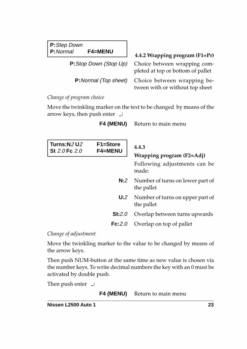
4.4.2 Wrapping program (F1=Pr)
P:Stop Down (Stop Up) Choice between wrapping com-pleted at top or bottom of pallet
P:Normal (Top sheet) Choice between wrapping be-tween with or without top sheet
Change of program choice
Move the twinkling marker on the text to be changed by means of thearrow keys, then push enter
F4 (MENU) Return to main menu
P:Step DownP:Normal F4=MENU
4.4.3
Wrapping program (F2=Adj)
Following adjustments can bemade:
N:2 Number of turns on lower part ofthe pallet
U:2 Number of turns on upper part ofthe pallet
St:2.0 Overlap between turns upwards
Fc:2.0 Overlap on top of pallet
Change of adjustment
Move the twinkling marker to the value to be changed by means ofthe arrow keys.
Then push NUM-button at the same time as new value is chosen viathe number keys. To write decimal numbers the key with an 0 must beactivated by double push.
Then push enter
F4 (MENU) Return to main menu
Turns:N2 U2 F1=StoreSt 2.0 Fc 2.0 F4=MENU
Nissen L2500 Auto 1 24
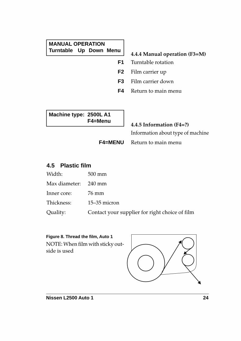
4.4.4 Manual operation (F3=M)
F1 Turntable rotation
F2 Film carrier up
F3 Film carrier down
F4 Return to main menu
MANUAL OPERATIONTurntable Up Down Menu
4.4.5 Information (F4=?)
Information about type of machine
F4=MENU Return to main menu
Machine type: 2500L A1F4=Menu
4.5 Plastic filmWidth: 500 mm
Max diameter: 240 mm
Inner core: 76 mm
Thickness: 15–35 micron
Quality: Contact your supplier for right choice of film
Figure 8. Thread the film, Auto 1
NOTE: When film with sticky out-side is used
Nissen L2500 Auto 1 25
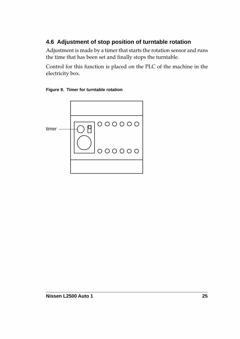
4.6 Adjustment of stop position of turntable rotationAdjustment is made by a timer that starts the rotation sensor and runsthe time that has been set and finally stops the turntable.
Control for this function is placed on the PLC of the machine in theelectricity box.
Figure 9. Timer for turntable rotation
timer
Nissen L2500 Auto 1 26
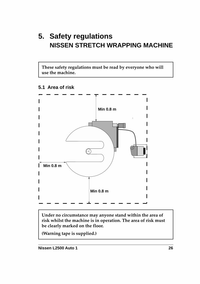
Under no circumstance may anyone stand within the area ofrisk whilst the machine is in operation. The area of risk mustbe clearly marked on the floor.
(Warning tape is supplied.)
5. Safety regulationsNISSEN STRETCH WRAPPING MACHINE
These safety regulations must be read by everyone who willuse the machine.
5.1 Area of risk
Min 0.8 m
Min 0.8 m
Min 0.8 m
Nissen L2500 Auto 1 27
5.2 Other safety instructionsGreat care must be taken to see that nobody comes between the loadedpallet and the turntable when the pallet is driven onto the turntable.
• The operator must not stand near the film carrier when it travelsup the film column. The risk area including the film carrier ismarked with warning tape to avoid risk of the operator putting afoot under the film carrier. Warning tape is supplied.
• Great care should be taken to ensure that no hand or arm gets caughtbetween the top clamp and the load when a top clamp is used.
• The machine must be shut off if it is not used during an extendedperiod or when the operator is not present.
• All electrical installation and repair work must be carried out by anauthorised electrician.
• After servicing or repairs, check that the safety bar, lift wire and allswitches, including the emergency stop switch, are fully operatio-nal.
• IN CASE OF EMERGENCY: PRESS THE EMERGENCY STOPBUTTON.
IMPORTANT!
The maximum load is 1 500 kg
The turntable must not be stepped on by any person.
Ensure that the fully loaded pallet is positioned in the centre ofthe turntable for the best possible stability.
Nissen L2500 Auto 1 28
6. MaintenanceTo ensure that your stretch wrapper works efficiently it is important thatyou regularly carry out maintenance in accordance with the instructionsbelow.
Service and repairs may only be carried out when the machineis totally disconnected from the power supply.
6.1 Cleaning of the pre-stretching unitBoth rollers of the pre-stretching unit must be kept clean to enable thefilm to run freely. Clean with spirit.
6.2 Care of the drive unitThe drive station is equipped with automatic chain tension. However,it may be necessary, after some time of operation, to exchange the chain(see separate instructions delivered together with the spare chain).
Besides, the drive station is equipped with two drive wheels whichmay have to be exchanged after some time of operation (see separateinstructions delivered together with the spare chain).
Check yearly both chain and drive wheels.
The chain is to be oiled regularly, 2–4 times yearly depending on oper-ation conditions.
NOTE! Lubrication is to be made with care to avoid oil stainson the drive wheels
NOTE! When the covering plate on the drive unit is beingremoved, be careful as the drive station contains chain tension-er which can cause damages if carelessly handled.
Nissen L2500 Auto 1 29
6.3 Care of the turntableKeep the turntable free of dust. Do not use cleaning fluid, since this cancause the drive wheel to slip if cleaning fluid is left on the periphery ofthe turntable.
6.4 Other maintenance instructionsElectrical connections: Check all connections and repair any damage orwear found. Replace with new parts when necessary.
Nuts and screws: Check that all nuts and screws are tightened thoroughly.
Notice plates: Check that all warning plates are firmly fixed and clearlylegible. They are there for your safety.