submitted in partial fulfillment of the requirements …
TRANSCRIPT

The Fabrication and Characterization
of Polyester and Vinyl Ester Sheet Molding Compounds
by
Diane Lynn Medved
B.S., Massachusetts Institute of Technology(1980)
SUBMITTED IN PARTIAL FULFILLMENTOF THE REQUIREMENTS FOR THE
DEGREE OF
BACHELOR OF SCIENCE
at the
MASSACHUSETTS INSTITUTE OF TECHNOLOGY
MAY, 1980
,i Diane Lynn Medved 1980
The author hereby grants to M.I.T. permission to reproduce andto distribute copies of this thesis document in whole or in part.
Signature of Author
Certified by.
Accepted by______
Departmegft of Chftical EngineeringMav 20, 1980
-- X \A David K. RoylanceE J . , Thesis Supervisor
4
Jack B. HowardChairman, Department Committee
., . . , ... .L. .
__
" , , . - I~I

THE FABRICATION AND CHARACTERIZATION
OF POLYESTER AND VINYL ESTER SHEET MOLDING COMPOUNDS
by
DIANE LYNN MEDVED
Submitted to the Department of Chemical Engineeringon May 20, 1980 in partial fulfillment of the
requirements for the Degree of Bachelor of Science inChemical Engineering
ABSTRACT
This project was oriented in two directions. The first developed anacceptable laboratory method for fabricating SMC plaques equivalent to thoseindustrially produced. The method was evaluated by comparing seven char-acteristic mechanical and physical properties of each experimental SMCplaque to those properties obtained from the commercially supplied SMCplaques. These values were, in turn, compared to the published literaturevalues. The SMC plaques were based on a general purpose polyesterbackbone (GP-ortho), a high performance polyester backbone (NPG-iso)
and a vinyl ester backbone (VER) of 20%, 25% and 30% glass fiber content.
The second purpose was to provide a unique characterization of eachof the cured resins and their respective SMC plaques. By using a FTIRspectrophotometer, unique spectra for each resin, GP-ortho, NPG-iso andVER was obtained. The ATR option was employed for scanning the SMC
plaques. The NPG-iso SMC plaques were made with no UV stabilizer, with0.1% and 0.2% UV stabilizer. The peaks were noticeably altered by thisaddition.
A UV absorbance spectrum showed that the NPG-iso polyester wasinherently more stable than the GP-ortho resin to UV degradation evenbefore stabilizers were added.
Thesis Supervisor: Professor David K. Roylance
Title: Professor of Materials Science and Engineering

TABLE OF CONTENTS
. . . . . . . . . . . . . . . . . . . .· · ·. .· · 2
LIST OF FIGURES . . . . . . . . . . . . . . . .
LIST OF TABLES . . . . . . . . . . . . . . . . .
ACKNOWLEDGEMENTS . . . . . . . . . . . . . . . .
1. INTRODUCTION . . . . . . . . . . . . . . ..
2. SHEET MOLDING COMPOUNDS . . . . . . . . . . . .
2.1 The Chemistry of Sheet Molding Compounds
2.2 SMC Thickeners . . . . . . . . . . . . . .
2.3 Typical Commericial Constituents of SMC ..
3. FABRICATION STUDIES. . . . . . . . . . . . ....
3.1 Industrial Needs . . . . . . . . . . . . .
3.2 Experimental Technique for Comparable SMC Fa
3.2.1 Materials.. . . . . . . .
3.2.2 Fabrication Technique . . . . . .
4. CHARACTERIZATION OF CURED PLAQUES . . . . . . .
4.1 Physical and Mechanical Property Test Result
4.2 FTS IR .... . . . . . . . . . . . .
4.2.1 FTIR Use with Polymeric Materials
4.2.2 Obtaining Spectra . . . . . . . . .
4.2.3 Resin Characterization . . . . . . .
4.3 Ultraviolet Absorbance . . . . . . . . .
4.3.1 UV Stabilization . . . . . . . ...
4.3.2 The UV Spectrum . . . . . . . . .
5. CONCLUSIONS AND RECOMMENDATIONS .. .......
5.1 Conclusions . . . . . . . . . . . . . .
5.2 Recommendations . . . . . . . . . . . . . .
6. BIBLIOGRAPHY . . . . . . . . . . . . . . . . .
e . .
· . .
*brica. . .· * e
· . .
.
brica-
.. .
.. .
us . .
.. .
.. .
. .* *
.. .
. .
.. .* *
. .. .
· ·
i i
· ·
· .
·
· .
i ·
iio
.···33. . . . 4.19
5
.· 6
..... 10
..... 10
... 16
...... 19
.....23
.. ,23
26.. .29
. . . . 29
. . .38
. . .38
. . . .40
. . . 41
. . . ..56
. . . 56
. . .. 58
. . . . .59
. . . . .59
. . .. .659
. . . . .60
ABSTRACT . . . .
,j
, .
. . . . . .- - -

List of Figures
Figure2.1.1 The Crosslinking Reaction of a Polyester with Styrene 11
2.1.2 The Synthesis of Bisphenol A Epoxy Resin 15
2.1.3 The Vinyl Ester Resin:Bisphenol A Epoxy Resin/Methacrylic Acid 15
3.2.1 SMC Formulations 28
4.2.1 The IRS Spectrum of the VER Resin Sample (ATR) 42
4.2.2 The Repeat Structure of the Vinyl Ester Resin 43
4.2.3 The IR Spectrum of the GP-ortho Resin Sample (Transmission IR) 44
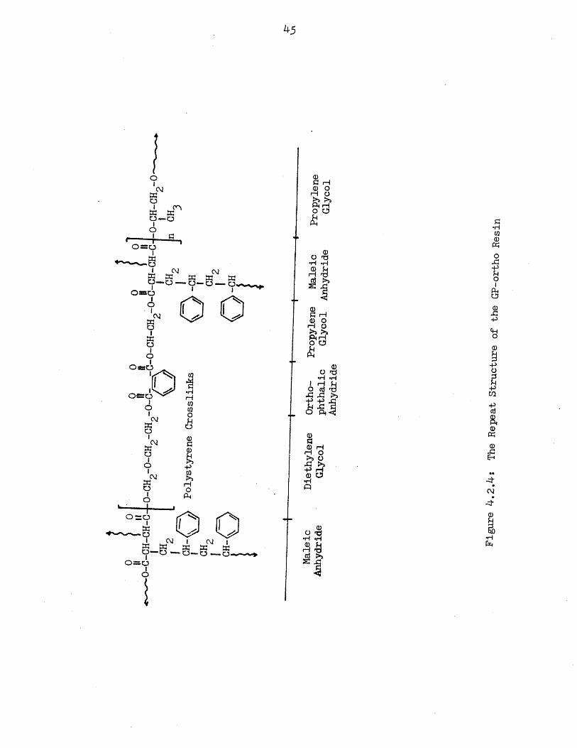
4.2.4 The Repeat Structure of the GP-ortho Resin 45
4.2.5 The IR Spectrum of the NPG-iso Resin Sample (Transmission IR) 46
4.2.6 The Repeat Structure of the NPG-iso Resin 47
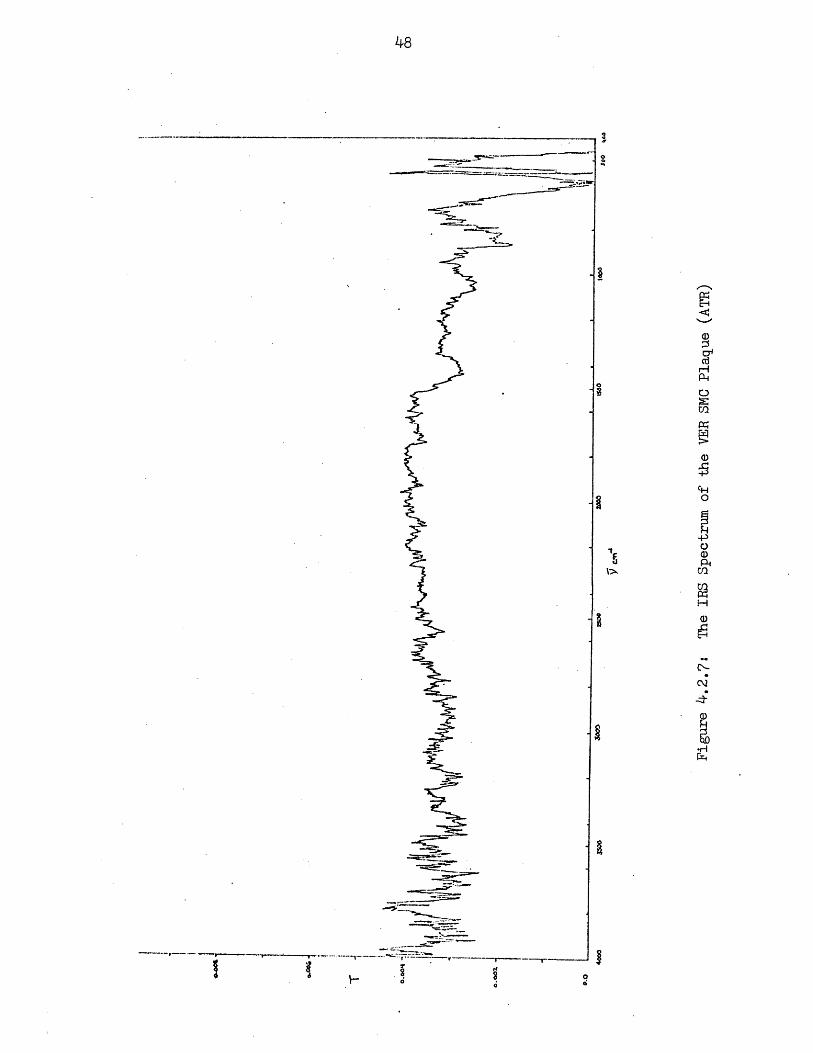
4.2.7 The IRS Spectrum of the VER SMC Plaque (ATR) 48
4.2.8 The IRS Spectrum of the GP-ortho SMC Plaque (ATR) 49
4.2.9 The IRS Spectrum of the NPG-iso SMC Plaque (ATR) 50
4.2.10 The IRS Spectrum of the NPG-iso SMC Plaque UV Stabilized with 51
0.1% UV5411 Additive (ATR)
4.2.11 The IRS Spectrum of the NPG-iso SMC Plaque UV Stabilized with0.2% UV 5411 Additive (ATR) 52
4.3.1 The UV Absorbance of the Polyester Resins 57

IIST OF TABLES
Table
4.1.1 Composition of GP-ortho SMC Experimentally Manufactured Plaques 30
4.1.2 Composition of NPG-iso SMC Experimentally Manufactured Plaques 31
4.1.3 Composition of VER SMC Experimentally Manufactured Plaques 32
4.1.4 Physical and Mechanical Properties of General Purpose Experimental
and Control SMC 33
4.1.5 Physical and Mechanical Properties of GP-ortho Polyester Resin
Based Experimentally Fabricated SMC Plaques 34
4.1.6 Physical and Mechanical Properties of NPG-iso Polyester Resin
Based Experimentally Fabricated SMC Plaques 35
4.1.7 Physical and Mechanical Properties of Vinyl Ester Resin Based
Experimentally Fabricated SMC Plaques 36
4.2.1 The Characteristic Infrared Absorption Peaks for the Three Resins 39
-
ii
iii
ii

5
Acknowledgements
I would like to express my gratitude to all of these people who have
helped me in some manner to complete this thesis. To Ming Tse for his time
and patience in teaching me to use the FTIR correctly; to Ahmed for his con-
tinual encouragement; to Adra Smith and Alli Efthimou for the artistic flair
they added to the drawings of this thesis; to Ruth Salomaa, Liza Bronaugh
and Heidi Grey for their much needed support and encouragement.
I would like to express my most sincere and humble thank you to Prof.
Dave Roylance and to Paul McElroy. To Prof. Roylance for his assistance in
outlining this work throughout the term; and to Paul McElroy for the innumer-
able hours of testings he performed for me, the unceasing patience he gave
me in all phases of this project and the inspiration he provided for its
completion.
Finally I would like to thank my sister Marilyn Medved upon whom I
most heavily relied during the final stages of the project. She has been
infinitely supportive and encouraging; and responsible for the form this
thesis finally took.
"For nothing is impossible with God."Luke 1:37
;
i
I
I
I
ti~..
.iI
I
i:
i
;I
s
�I
9i
�1JI
89:i
aB
:i
ri
i

1. INTRODUCTION
Sheet molding compound (SMC) is an integrated, fiberglas-reinforced
resin composite that can be manufactured by an automated, continuous pro-
cess. The polymeric composite is composed of an unsaturated polyester or
vinyl ester resin which is reacted with various organic and inorganic
substances to produce a moldable paste. The SMC has several advantages
for many areas of application. The low shrink/low porfile SMC provides
design engineers with a new material that has the structural and dimension-
al requirements which have previously been unattainable with other glass
reinforced materials. The development of SMC has allowed a greater
variety of sizes and shapes to be molded, more automation and process
control, and, thus, a more favorable cost/performance relationship. The
molded parts hold their contour and dimensions over a wide range of tem-
peratures and physical stresses such that they may be designed to function
alone or in conjunction with metals. The thermal coefficient of expansion
of SMC's allows compatibility with metal components. A single SMC part
can replace metal assemblies of many parts and fasteners producing a
greater efficiency in handling the entire part. The glass fibers, which
reinforce the SMC resins, give performances equal to or better than metals.
N The excellent strength-to-weight ratio provided by SMC's is a result of
the lightweight SMC--35-40% lighter than its metal counterparts. Since
there are fewer molds and processing steps required to produce a SMC
part, the tooling cost is reduced; and with the low shrink/low profile
SMC the surface smoothness requires little work to make a finished pro-
duct thus reducing the final product cost further. The last categorical
advantage of SMC products is the uniform corrosion resistance that prevents
rust deposits from forming on the composite--due to the composite's
chemical structure, these deposits are non-existent.

7
Notable growth has been experienced with SMC in the automotive,
appliance, business machine, furniture, electrical/electronic and bathroom
component markets, as well as in toys and medical equipment.
The automotive applications include front end panels, deck lids,
trunk front fender-hood assemblies, heater and air conditioner housings.
Numerous cash register and business machine housings, internal components,
keyboards and access panels are SMC products. Unsaturated polyesters
are used for bathroom components because design flexibility and process
selection offer cost/performance advantages. Reinforced unsaturated poly-
esters are used in other applications including fishing rods, golf club
shafts, farm silos, protective helmets, trays and bins, rapid-transit car
components, bus stepwells, swimming pools, playground equipment and air-
craft interior paneling.1
The vinyl ester resin has found increased usage in the automotive and
transportation industries because this resin has better moldability, higher
toughness and higher temperature performance than the polyester resins.
The inconsistent quality of the polyester resins has produced molded parts
with unwanted porosity, sink marks, low physical properties, cracking,
wrinkles and waves. Cutshall and Pennington have shown why the vinyl ester
resins have eliminated those problems. Hawthorne et al have documented
industrial cases showing an experimental vinyl ester resin that has been
developed to impart an added degree of toughness where severe mechanical
abuses are involved. In addition, this product exhibits low exotherm, high
bond strength and reduced shrinkage coupled with the corrosion resistance
found in most SMC. These properties make the high quality vinyl ester based
1W J Connolly, "Unsaturated Polyesters," Modern Plastics Encyclopedia,1975-1976, pp. 61-62.
?!

8
SMC ideal for such critical service as uranium recovery mining and high tem-
perature fume handling equipment where adhesion and abrasion resistance,
chemical resistance to extremely caustic and acidic conditions and low shrink-
age and dimensional stability are especially needed.
A significantly large portion of the SMC being commercially sold today
is oriented towards an outdoor market. These products include the auto-
motive industry as well as household and commercial products. The first
industrial product based on SMC was a cable distribution box manufactured
in Germany in 1958. Since then the field has grown through light fittings
for street lamps, boat shells, small furniture items, the low profile
additives to improve SMC performances and most currently the wide variety
of vinyl esters that provide specific properties to the SMC. This space
of time has allowed a long term behavior analysis of SMC to be studied.
Weathering tests have been conducted to evaluate the chemical, thermal
and oxidative stability of the SMC. Factors including color changes --
fading and/or yellowing, loss of gloss, glass fiber erosion, mechanical
properties changes -- flexural strength, water immersion, warm moist air
and storage in soil were measured on these actual first SMC's commercially
made.2 Accelerated weathering tests hvae been designed so that more
tests are possible in a shorter time span. These tests showed that unless
suitable stabilized and coated, fiber-reinforced composites are subject
to photoinitiated oxidation which results in a degradation of the resin
surface and an eventual reduction in'the composite's mechanical properties.
2Rainer Gruenewoald and Oskar Walter, "Fifteen Years Experience withSheet Molding Compound", 3th Anniversary Technical Conference, ReinforcedPlastics/Composites Institute, The Society of the Plastics Industry, Inc.,
1975.

9
To quantify the degradation many variables must be controlled. The types
of resins used to fabricate SMC are the various grades of polyesters and
the vinyl ester family. Before these can be made into SMC they must be
screened.for consistent resin constituents so as to keep the reactivity of
the compounds controlled.
The objective of this thesis is twofold: to develop a method for
fabricating SMC plagues such that their mechanical and physical properties
are equivalent to the industrially produced SMC, and to spectrophotometrically
identify the initial characterization of a general purpose polyester, a
high performance polyester and a vinyl ester resin in the cured and SMC
states. A combination of the transmission IR spectroscopy and the Attenuated
Total Reflection (ATR), gives a fingerprint of the cured resins and the SMC
products which may be used later to monitor chemical modifications in the
resins and to chemically describe SMC weathering. The UV absorbance
spectra gives a relative ranking of the cured resins based on their
stability to UV degradation.
1
d
'1
B
t
E
B
I
i 1
,I
iI
:.
I
-AMOMM.�-

10
2. SHEET MOLDING COMPOUNDS
2.1 The Chemistry of Sheet Molding Compounds
Unsaturated polyester resins are the condensation products of multi-
functional acids and alcohols. The polyfunctional alcohols, specifically
neopentyl glycol, diethylene glycol and propylene glycol, react with the
carbonyl functionality of the acid to produce a condensation polymer:
O-R-cm t - .--t -H--- C,0The reaction can proceed with an anhydride in place of the acid, producing
a polymer without the elimination of water as a by-product. Most often,
and in the case of the polyesters used in this thesis, a phthalic acid is
used in combination with maleic anhydride as the acid half of the condensa-
tion reaction.
Polyester resins are liquid polymers usually synthesized with the
application of heat and a catalyst. The crosslinkable resins must be made
from unsaturated acids and anhydrides reacted with a glycol in a direct
esterification reaction. The unsaturated requirement is needed because
there must be double bonds within the main chain to propagate the crosslinking.
A typical polyester resin consists of orthophthalic acid, maleic anhydride
and propylene glycols
oa o a 0H~o-nes, ,C~ -c 4t c,~-c l. ~---> o'- t -O-c - -o i -C-c- =c-C- C o
The unsaturation along the polymer chain provides crosslinking sites when
reacted with vinyl monomers such as styrene. The peroxide initiator and
heat catalyze the reaction in the following manner in Figure 2.1.1:
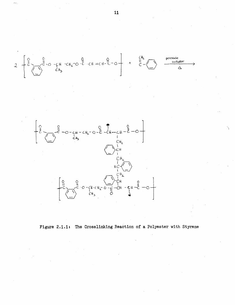
11
b
/ /CNC - -CO ·C C- c0
f-R C R3
c)'-.h
II_
_- 1tel
flrtic~tVvelfokienmads* t I
C F\
T? O--- - c, '- (H._ .-CU .---
Ibus~~~~~~~~~~~t I
c~,, l\;
C.bIA
.! (A
tC\ t -- CI -0
Figure 2.1.1i The Crosslinking Reaction of a Polyester with Styrene
I cC)
£2
:�gi.IqI AllR
_.
Yi
E

12
Styrene is the most common crosslinking agent used. Methyl methacrylate
and other vinyl derivatives provide adequate crosslinking also. Crosslinking
is initiated by the thermal decomposition of orgailc compounds, such as
peroxides, hyperperoxides and peresters. Ultraviolet radiation at room
temperature and electron bombardment will also initiate crosslinking. Once
monomer has been added to a polyester resin, it will have a tendency to
polymerize. Long term storage of resins at room temperature is accomplished
by an inhibitor, typically a hydroquinone or a benzophenone. The inhibitor
acts as a hydrogen donor to neutralize free radical formation in the resin.,
The polymerization reaction takes place in an excess of monomer to
insure all unsaturated bonds are reacted. The reaction is exothermic and
as the crosslink density increases the viscosity increases. At sufficiently
high crosslink density a gel forms, continued crosslinking yields a hard,
glassy vitrified solid. Molecular mobility is sufficiently inhibited in
the glassy state, terminating the reaction. Post curing of the polymerized
solid above T is usually done to insure that all unsaturated linkages aregreacted. A typical polyester resin will have 3% to 7% unreacted double bonds
at the completion of cure,
Polyester resins are seen to offer great flexibility to formulators in
selecting resins to tailor-make the resin to a selected spectrum of desired
properties. The wide variety of acids, glycols, monomers, initiators and
inhibitors available makes a high performance polyester resin feasible,
especially with the addition of special purpose additives to impart ultra-
violet stability and flame retardency. A general purpose rsin was described
in the crosslinking reaction above. An improvement over this formulation
substitutes a neopentyl glycol, maleic anhydride, and isophthalic anhydride
into the resin backbone. With this variation in main chain backbone a highly
weatherable, tough base resin for SMC use is obtained. The isophthalic acid
IT
iI
i
f
i3
-1,
i

13
is used to produce more viscous resins which cure into tougher more heat
and water resistant solids. The crosslinking in the high performance poly-
ester is produced from the methyl methacrylate and styrene monomers which
copolymerize to produce cured polyesters of superior durability, color
retention and fiber erosion resistance. The empirical chemical reaction is:
a. ''- 0 ''~~ - C .- 0- C = -t .c\ 0
L. -C -C
AI l tCfow
.o I c- . - -o4 ,-3 a RIL I- _ _l
I
' i 4I \ 'clf;" C)~~~~~
Vinyl ester resins are the reaction products of epoxy resins and ethylen-
These resins may be described as epoxy acrylates which combine the applica-
tion features of unsaturated polyester resins. Commercial vinyl ester resins
employ Bisphenol A, Tetrabromo Bisphenol A and Phenolic Novalac epoxy resins
reacted with acrylic, methacrylic, crotonic and cinnamic unsaturated acids.
Suitable formulations of these reactants yield vinyl-ester resins that have
ttU-C__ - G1-0V* r ( ~o -t YU-1-To-c- -,AT -UC,~~~~~
c _I
:1 c~~~~~~~~~~~~~~~~~~~~~~~~~~~~~~~~~~~~~~. �jII
AA
-L%;a"-L UI~eLUU4;Zat'W" 1LU~1iW~a4:WUXVJ--LU allUSJ UZ:'bb.L.L.EL&WU W.LU1 5c117MI MWWmer.i

14
a variety of properties.
The most ommon industrial vinyl ester resin used to make SMC is for-
mulated using Bisphenol A epoxy and methacrylic acid. This resin may be
crosslinked with styrene monomer to yield a highly weatherable heat resistant
cured product with good mechanical and physical properties. The reaction
scheme is presented in Figure 2.1, and the final vinyl ester resin is in
Figure 2.1.2.
A few observations about the crosslinking technology of vinyl ester resins
reveal several reasons for the expectation that vinyl ester based SMC is
considerably more weatherable than polyester resin based SMC. Crosslink
density of epoxy resins is directly related to the degree of substitution
along the backbone chain. Increasing degrees of substitution generally
reduce crosslink density and water permeability. This is expected due to
spreading and opening of the epoxy backbone structure caused by interstitial
group addition within the chain. Low reactive, highly unsaturated ring
structures in epoxy chains yield lower crosslink densities than the compact,
ring situated structures.
High thermal stability of cured laminates is one of the main reasons
for using a vinyl ester resin in an SMC formulation. This property of
cured epoxy resins is associated with stable aromatic ether and ester
linkages along the epoxy chain. Aliphatic ether and ester groups yield
-somewhat lower thermally stable cured resins.
Methacrylic acid has proven to be the most commercially useful for
producing maximum deterioration resistant vinyl ester resins. Enhanced
weatherability is provided to the epoxy resin backbone from a terminal
methylene group that is thought to cause a shielding effect on the adjacent
main chain ester linkage. Copolymerization with styrene provides additional
shielding to the unsaturated bonds of the methacrylic linkage after crosslinking,
FX

15
Figure 2.1.I The Synthesis of Bisphenol A Epoxy Resin
0 n
Phenol
C43\ I Bisphenol A
(t ?I-Cp 1-s
Acetone
Epichlorohydrin
ct4
-> k4 O ._~ "tlI
e0L3
tI 0Q
Bisphenol A
c0-0c4:-c 1£ __0 __,
Chlorohydrin Intermediate
I kOj,
C';'" e~e/0\~~cvt~- CMc~ -C4-~ W - oC -tN- ¾ -AC
/ 0 \-,O-CA.j- \_4 -A 0
Bisphenol A Epoxy- Resin
Figure 2.1.3: The Vinyl Ester Resint Bisphenol A Epoxy Resin/Methacrylic Acid
C4 3 0 i t ICM l-N=C UN:=:/cci~ CHCH LH C - -- -l J.4-t o- (It4,- ~H- C.h

16
because of the steric hinderance of the phenyl group present in the styrene
monomer.
All of these resins are suitable for SMC fabrication, each having its
own inherent properties. To get the resin paste into a SMC form with acceptable
commercial processability, the viscosity of the resin must be increased to
a handla be aegree.
2.2 SMC Thickeners
Chemical thickeners are the ingredient in SMC that differentiates this
material from other fiber reinforced thermosetting polymers. Thickening agents
for SMC are in the family of alkaline earth oxides and hydroxides with
calcium and magnesium oxides (hydroxides) most frequently used. Chemical
thickeners initiate the reaction which transforms the mixture of SMC ingred-
ients into a handlable, reproduceable molding material. SMC resin formula-
tions contain 1% to 3% thickener, it is the final ingredient added to the
resin system and begins the chemical thickening process immediately.
Several articles on chemical thickening and maturation control of SMC
paste have been published., 3 Much of the information available on SMC
thickening in these articles are patent reviews describing the compounds used
to thicken various resin systems. General criteria of the thickening reaction
may be discerned from the discussions in those articles:
1. Thickening must be slow enough to allow wet-out and impregnationof the glass reinforcement.
FB.Alvey, "Study of the Reaction of Polyester Resins with MgO,"J. Poly. Sci, Part A-i, 92233 (1971).
K.N. Warner, "Mechanism of the Thickening of Polyester by AlkalineEarth Oxides and Hydorxides," 28th Annual SPI Conference, (1973).
3F. Fekete, "Thickeners and Low Shrink Additives for Premix and SMCSystems," 25th SPI Conference, Washington D.C., (1970).
:;
ii
i'
31t

17
2. Thickening must be fast enough to allow the handling required bymolding operations as soon as possible after the impregnation step inorder to keep the amount of sheet in storage low.
3. Thickening must give a viscosity at molding temperatures low enoughto permit sufficient flow to fill out the mold at reasonable press pressures.
4, Thickening must give a viscosity at molding temperature high enoughto carry the glass reinforcement along as it flows in the mold.
5. Thickening must stop in the moldable range to give a long usefulshelf-life.
6. Thickening must be reproducible from run to run.
Alvey carried out one of the earliest studies on the nature of the
thickening mechanism of polyester resin by magnesium oxide. The chemical
thickening agent was systematically added to the resin in incremental steps
of concentration and the viscosity checked with a Brookfield viscometer. Results
were presented as a series of log viscosity (cps) vs. time, (hr) curves. It
was found that increasing the concentration of MgO significantly increased
the rate of viscosity development in the initial stages of chemical thickening,
leveling off with increasing time. Alvey proposed that chemical thickening
occurs by two mechanisms. An initial equilibrium reaction yields a higher
molecular weight salt-linked polymer with little viscosity increase, then a
second viscosity increasing reaction of MgO with the polymeric salt occurs.
Alvey suggested that inter-chain bonding through dipole interactions between
MgO and the salt were responsible for the noticeable viscosity rise of the
polyester resin. Warner5 depicted the first stage of chemical thickening of
polyester resins as an acid-base reaction driven by the electrostatic attrac-
tion between oppositely charged ionic centers. In this reaction mechanism,
a Salt is formed between carboxyl groups of the polyester resin and the metal
ion of the chemical thickener (pictured at the top of the next page). Similarly,
4Alvey, p.2237.
5Warner,
4

18
&L:LOA C' - kRC cO M cAtO A
<CX W t R.mom co 0 4 C) tCOG)) A t 0
chemical thickening of a polyester resin with a hydroxide agent proceeds:
(coas + 4&go CY 2)OH (4 W ,
Warner proposed that since the second stage of chemical thickening is
temperature controlled, a diffusion controlled mechanism for the reaction
was implied. Two possible diffusion mechanisms were proposed by Warner.
The first suggested that bridging occured between adjacent polymer molecules
through hydrogen bonding between carboxyl and ether oxygens, in which these
oxygens acted as electron donors in the hydrogen bridge. Addition of electron
acceptors, through the glycol in the chain or the water generated by the
reaction, would complete the bridge and cause thickening to occur. The
second diffusion mechanism proposed by Warner involves the creation of
coordination Implexes between the polyester carbonyl groups and the metal
-C
-".:, ' 0'
. .. ,-..c - ,, . o , --
0
The coordinate complexes formed by the reaction above result in network for-
mation and an increase in the viscosity of the resin. Warner suggested that
this diffusion mechanism accounted for the effect of water on the thickening
process seen in experimental work on thickeners. He argued that addition of
large amounts of water to the thickening reaction would reduce viscosity by
displacing the complexes formed between the carbonyl groups and the metaldisplacing the complexes formed between the carbonyl groups and the metal~~~~~~~~·
19
ion with the much stronger coordinate complexes of the metal atom with the
water molecules. In this way, overall chain to chain interaction and vis-
cosity would be reduced with formation of complexes with water by the chemical
thickening agent.
The vinyl ester resin (VER) differs from the polyester resins in the
terminal unsaturation. This difference affects the thickening properties of
the vinyl ester resin. VER is thickenable with the addition of MgO, but the
kinetics differ from that for the polyesters. Only slight changes in the
matured viscosity are apparent for large variations in MgO content added.
The thickening virtually stops after the initial viscosity increase, implying
a longer more stable shelf life. The thickening rate in VER is unaffected
with a CaC03 and low profile additive, a combination that would drastically
6increase the thickening rate of the polyester. The mechanism for chemical
thickening in vinyl ester resins in still an area of research that needs work.
2,.3 TyPical Commercial Constituents of SMC
In addition to the crosslinked and thickened resin paste thus far out-
lined in SMC fabrication there are numerous additives incorporated for
specific properties. The reinforcement fiber is E-glass and generally is
two inch long strands distributed evenly through the resin for uniform
reinforcement.
The low nrofile. LP-40. is added in the liauid state to the polvester
resin. It will increase the rate of cure by increasing the viscosity with
up to 6.7% pbw of LP-40. It is added to prevent shrinkage with the accom-
panying micro-cracking or surface depressions. The low profile resin works
in the following manner.7 As the temperature increases, the polyester resin
6R.D. Farris, R.J. Jackson, W.V.Breitigam, "AThickenable Premium VinylEster for SMC Applications," 35th Annual SPI, (1980).
7JR Molloy, "Function and Purpose of SMC Ingredients," Memo to theManufacturing Development Department of General Motors, 9/12/78.
t,

20
starts to crosslink; the thermoplastic resins do not crosslink. As the poly-
ester resin crosslinks, free styrene and unreacted, unsaturated polyester
resin are pushed and drawn into the thermoplastic reservoirs. As the
temperature increases, the thermal expansion of the thermoplastic creates
the force necessary to overcome the shrinkage caused by the polymerization
of the polyester resin. By this time the matrix is fairly well cured and the
unsaturated polyester and styrene now cure and form a small void in the
thermoplastic phase. The mold is opened and as the part cools, the thermo-
plastic phase and matrix both shrink. When the matrix cools to its glass
transition temperature, it shrinks much less than the thermoplastic phase.
The thermoplastic phase then pulls away from the matrix thus creating another
void in the material. The final void helps relieve any internal stress that
might be in the part. This theory was formed from the coefficients of
expansion, glass transition temperatures and polarity effects as the
polyester and thermoplastic resins interact.
Polyethylene powder finely ground is added to SMC formulations to aid
the flow of the compound during molding and to improve the surface smoothness
of the molded parts.
Inorganic fillers comprise virtually 50% to 60% of any SMC formulation
and are primarily added for cost reduction. In addition, fillers promote
flow of the glass fiber reinforcement during molding and enhances the
appearance of the final product. Filler particle size is an important con-
sideration, small particles promote better flow without degrading the glass
reinforcements, giving improved surface appearance over coarse particles.
Viscosity control of SMC paste may be accomplished by incorporation of a
combination of coarse and fine particle sizes.
Calcium carbonate (CaC03) is the most common filler used in SMC and may
be used to high filler loadings. Hydrated alumina (Al(OH)3) fillers are
-
i
21
incorporated into SMC formulations to provide flame retardency while maintaining
good electrical properties,
Mold release agents are selected for use in SMC formulas on the basis
of their melting points being just below that of the molding temperature.
In theory, the mold release agent melts at the SMC mold interface forming a
barrier to adhesion by reducing the resin melt viscosity and controllong
friction between the metal mold and the SMC paste. Lubricants are classified
as either internal or external depending onwhether they function within the
polymer or between the polymer and metal surface of the mold. Internal release
agents are compatible with and dispersed into the SMC paste and, upon
melting, take up vacancies between polymer chains, thereby decreasing the
resins' melt viscosity. External mold releasing action arises from incom-
patability between the lubricant and polymer, forcing migration to the resin
(paste) surface where friction is reduced at the mold. Zinc stearate, calcium
stearate and stearic acid are the most commonly used internal lubricants.
Normally, mold release agents are used in concentration less than 2% of the
total weight of the SMC compound to avoid reduction in mechanical strength
and objectionable surface appearance.
The catalysts, or initiators, cause the rapid reaction of polymer and
monomer to achieve final cure within a short time period by free radical
polymerization. Commonly used initiators include benzoyl peroxide, cumene
hydroperoxide and t-butyl perbenzoate.
Promoters are sometimes used to accelerate the decomposition of organic
compounds. Coblat napthenate and tertiary amines are used on the order of
0.008% to 0.02% concentration. These operate by an oxidation-reduction
mechanism, where the cobalt napthenate is the reducing agent.
Inhibitors may affect the curing, weatherability and color stability of
polyester laminates. Polyester zesins may be inhibited by using small
:,4.g'

22
(0.02) of materials like polyhydric phenols. This category includeshydroquinone and benzoquinone. The inhibitor provides long storage timesat room temperature, keeping any premature gelation from forming, specificallyany styrene monomer from polymerizing.
1

23
3. FABRICATION STUDIES
3.1 Industrial Needs
It is vital to the SMC industry that the fabrication of the SMC prod-
ucts be consistent. Because of the vast number of variables that can affect
the properties and performance of SMC, a closely monitored fabrication proc-
ess must be devised. It is essential that the raw materials be stored in a
dry, covered area for minimum moisture absorption, and in an area unaffected
by temperature fluctuations. Experimentally it is much easier to make batches
of SMC rather than setting up a continuous process. If the disadvantages
of batch mixing can be prevented, then SMC plaques made experimentally can
be compared to those industrially made. The potential hazards include the
incomplete mixing of resin paste and glass fibers caused by the premature
thickening of the resin paste. This causes incomplete wet-out, dry glass
in the finished SMC, producing poor mechanical properties. The second hazard
is the inconsistent batch-to-batch properties of SMC compounds; commercially
rlrcss rrrr7~ Ial| uuc vi u gU13 We PIVUUU1ei a heeb VI of constnt welh wn
fiber glass content tolerance of + 2% or better. These inconsistencies are
controlled by the following fabrication and molding parameters.
The sheets must have a uniform weight per unit area throughout the
entire sample. This is accomplished with serrated steel rolls which can
apply different pressures to the premolded resin/glass mats depending on
the desired product. The rollers are set for a maximum pressure such that
internal fiber shifting does not occur. A "pick" roll pricks holes in the
polyethylene cover to allow the entrapped air to escape. Air bubbles in
the final SMC plaque are controlled in the premolding stages by non-violent
mixing of the resin; application of resin to polyethylene sheet followed
by the glass mat; a center-outward pressure on the laminate for even resin

24
distribution; and elimination of air bubbles from one ply before the others
are added, Ideally the product must be tack free for easy handling and
molding.
An even temperature profile across the molding surface is maintained
so that premature gelation does not occur. The molding temperatures range
from 143-155° C and the compression molding pressures range from 5500-8275
kPa. Because the low shrink/low profile SMC plaques are highly filled glass
loaded systems, it is essential to have higher compression pressures to pro-
duce a sheet surface free of the wrinkles and sink mark imperfections found
when inadequate pressures produce under-cured specimens. The mold pressures
provide satisfactory flow and fill out of the paste so that the glass fibers
can not "orient" themsleves - a property carused by excess flow in the mold
resulting in wide variations of the physical properties leading to weaknesses.
The press closing speed must be between one and ten seconds; if it is slower,
a pre-gelation of the paste occurs causing unhomogeneity of the structure.
The curing time, the time required under for the SMC sheet to gel will
affect the ultimate surface hardness.
3.2 Experimental Technique for Comparable Industrial SMC Fabrication
3.2.1 Materials
The control SMC plaques produced by B. F. Goodrich Company from Ashtabula,
Ohio contain the following ingredients:
Polyester resin 65 parts by wieght 29.79 % by weightLow profile polyester resin 35 16.04Calcium carbonate 112 51.33Tert-butyl perbenzoate (TBP) 1,.2 0.550Magnesium oxide 1.0 o.458Zinc stearate 4.0 1.83Glass fivers 25 % by weight of resin
The control plaques utilize the general purpose polyester resin as opposed
to any higher grades of resin.
I
1
I

25
GP-ortho This is the general purpose unsaturated polyester resin
used to make the experimental SMC plaques. It is supplied by Pioneer
Plastics (Auburn, Maine) under the trade name of Pioester 220. Chemically
it is 1.5:1 molar ratio of orthophthalic anhydride to maleic anhydride in
the resin; and 0.32:2.18 molar ratio diethylene glycol to propylene glycol.
The acid number ranges between 25-30 and is approximately equal to its hy-
droxyl number. The resin contains 40% styrene; cobalt naphthanate is added
at a level of 5 ppm to control the exotherm. It is catalyzed by tertiary-
butyl perbenzoate (TBP) at the optimal level of 2% by weight of resin. The
low profile resin used is polyvinyl acetate.
NPG-iso: This unsaturated polyester is also supplied by Pioneer Plas-
tics (Auburn, Maine) but is a 1:I molar ratio of isophthalic to maleic
anhydride on a 2 molar neopentyl glycol basis. This resin is uncatalyzed,
without UV stabilizer and has an acid number of 25-30. The methyl methacry-
late content is 10% and the styrene monomer content is 37%. Due to the low
boiling point of methyl methacrylate, 9000, the benzoyl peroxide (BPO)
catalyst was used as the initiator. BPO decomposes at 930C allowing the
methyl methacrylate to react and crosslink the polyester before it volatil-
izes, as a non-volatile cure of the SMC paste inside the mold is desirable.
TBP does not decompose until 1180°C and would be ineffective in producing
proper cure, volatilizing all the methyl methacrylate before it could cross-
link the resin. BPO was used in a 98% active powder that was first dissolved
in a small amount of styrene and then added to the SMC resin at 1% active
BPO by resin content.
VER: Vinyl ester resin is sold under the trade names of Epocryl (Shell
Chemical Co.) and Derakane (Dow Chemical Co.). The Derakane 788 resin was
chosen because it was readily available, and is used industrially to make
-
Ij
I
iI
i,iiii
iI
i
iii
i
i
i
i

26
igh strength SMC. it is a pre-blended one-component low profile xesin
hickenable by MgO. The most acceptable catalyst is TBP at a 0.3% level
ased on VER resin content. This level gives a fully cured homogeneous solid
rith good physical and mechanical properties.
All the SMC formulations are outlined on Table 3.2.1 for an overall
omparision of constituents,
3.2.2 Fabrication Technique
The fabrication procedure was designed to make experimental SMC plaques
quivalent to those commercially manufactured. The procedure closely resembles
he commercial operation except that random chopped glass roving is normally
sed industrially while a galss fiber mat is used in these cases. This pro-
ides easier handling and a more even glass distribution in the experimental
laques. This is the compression molding technique.
1. The fiber glass mat is cut into the mold dimensions (.2794 x .3556m),
md the polyethylene cover sheets are precut to slightly larger dimensions.
he numbler of plies to be used are weighed - three were found to provide
n optimum thickness; and, the proper weight percentage of the glass in the
aminate is determined from this weight.
2. The total resin content was fractionized according to the glass
!iber weight and the industrially supplied control plaque percentages. These
re listed in the description of the control SMC plaques.
3. All the components are weighed and mixed in a safety hood using
high speed air powered mixer and propeller. It was thoroughly mixed 10
inutes so that a smooth consistency with minimum air bubbles resulted.
land mixing produced chunks of CaC03 in a most unsatisfactory manner.
4. The MgO thickener was added just prior to sample fabrication since
,he resin noticeably thickens within two hours making handling and fiber
ret-out very difficult.

27
5. The polyethylene cover sheet was laid on flat surface in the hood.
A layer of glass mat was saturated with aliquots of resin in a manner to
alleviate air entrapment. Another polyethylene sheet was placed on top
to provide a surface upon which a serrated roll under constant pressure
could spread the resin evenly to achieve full wet-out. The even resin dis-
tribution overcomes some of the disadvantages of the batch system, and
avoids the problem of premature resin thickening and non-uniform specimen
thicknesses.
6. One of the polyethylene sheets is carefully removed and successive
glass ayers and resin aliquots are added repeating the rolling process
between each ply to ensure even distribution, no air bubbles and uniform
sheet thickness, Three plies were found to provide the thinness necessary
for the SMC sheets. After the final layer was saturated with resin all the
edges of the polyethylene film were taped closed with two inch masking tape
to contain the mixture. The SMC/polyethylene package was tightly wrapped
in heavy duty aluminum foil to prevent styrene loss during the two day mat-
uration process.
7. The mold is preheated to 1500C in the hydraulic press. Each plaque
is compression molded under 6895 kPa pressure for 10 minutes. The time
lapse for press closure is ten to fifteen seconds; this brings the pressure
from zero to the maximum pressure. This compression cycle is consistent
with standard commercial SMC production.
The experimental procedure has potential toxicity problems with styrene
vapor exposure. The proper use of the hood, safety glasses, lab coats and
gloves kept the procedure within acceptable standards.
ii
I
i.
i:
Ir

28
0 a
a) a)0
I > C 0 N o t a N .5,,,, , g o O M {4 0 N m r od a '~- E ~ ·r..39 I
w $f a, 9 d rl 55~~ry~ W~~ ~~~~ m.~5 o~~~~oa~~~,- ra3 fIo r3· rf $3~~~~~~~~ ~ ~~~~~
t o - rd
O3
U) ) 0
I
0H z0o H
0
HH
0 +11oZ Mc
0 '0
) U cd0o :N o
PA U ·x m i,
00I U) I '
d I 0
II c o4 0 00
0 (. . .o
r,o
Co¢t Uli4I q$.H
PP4
o ·t
o 0
·.,, ~ , o*H H9 N zd E-4 0
000a)
a) o0 NO U
0 , I
-4 0
C H O O+0 0
r, o a0 0 0
C 0 4 H H - L a H 0~r 0, * H 0 0 -$CrH 0 0d OO a P
CY2
0E
. -
._i _

29
4. CHARACTERIZATION OF CURED PLAQUES
4.1 Physical and Mechanical Property Test Results
Experimental SMC plaques were fabricated using the technique described
in section 3. These plaques were made from each of the three resins, GP-
ortho, NPG-iso, and VER, at three glass fiber loadings: 20%, 25%, and 30%
by weight. Tables 4.1.1, 4.1.2, and 4.1.3 give the percentages by weight and
representative aliquots in grams of all the constituents in each of the SMC
plaques sectioned by glass fiber loadings. The percentages are based on the
industrial formulations given for the control plaques in section 3. The con-
trol plaques were of 25% glass fiber only. The specimens were cut from the
fabricated sheets in a manner to' test the uniformity of the sheet. Thickness
variations were within 5% of the 3.175 mm nominal thickness. Each experi-
mental plaque of the GP-ortho backbone has the same chemical formula as the
control so that the only variables in comparing the industrially manufactured
control with the experimentally made plaques are the glass fiber loadings
and specimen thickness. The following mechanical and physical properties
of the commercial and experimental plaques can be directly compared to the
published literature values as an indication of fabrication reproducibilityt
flexural strength, flexural modulus, notched Izod impact strength, tensile
strength at yield, tensile modulus, ultimate tensile elongation and density.
The results of the testings are in Tables 4.1.4, 4.1.5, 4.1.6 and 4.1.7.
Table 4.1.4 shows that the experimental and control plaques, both of 25%
glass fiber loading, compared well to each other and to the literature values.
The literature values were published in "Sheeting Molding Compound", Owens/
Corning Fiberglas Corporation, 5-TM-6991-A, 1977. All other experimental
plaques corirespond to published data, although a majority of the testing
was centered around the 25% glass fiber plaques.
-

30
n a o co g0I O 4O H rH
'I
o n . . .
r' CO -°
NN 0c H HH0
co co X H 4
Ws, DHH o ou~~ lgQI I V- --, -1T4
;W
' 0
E4 d0~~~ *H . Q
0 0rU h0 N O(I, A 4 S I 0 *
to30Ca,Cd
0
I
Ii
J
rt0
oH,
o
o :
.4-
oX* u
4 a,
0)
0$
0P
.,-
'S0E-.*d

31
G E n n o o on (Y OO H
+1,ctit H I
0 10 co o ;O cn * .4 . .r- U %o
C, C CN N ) V) vUncn o 4 o \n c H
G < 3 e OV o rC'- HRL H
C,)
w -IUa I
0 qfi ,a101
co co o n VON o H H
Cr~`f M
C\2 C- \ ) Co \ n C\cr , . .
co 0 O ( C- <ON \O H H 0 0C" H-
rHo)
a)a)
r -
H -0 a) o0
U4 to _ ME:
U)o m
H
Or-IOH
P.IodH H
. r-; : E)PAC;
-PC+C) .,,I
01
WoI1
a)
rd
ON0a)
*L

ocic a's Hco .
r H
cO co n
~ H -Z -
co co n \H HrV)CQ *.^
~~~u1~u
0C\2 a) cO r
1 H HI c) co '91 r4 r4
UN U-
MU)z:z4)4-'
4-)(I00
a)ci)
P P~2 N
0cdV~
oO H
o o
o r4
H ') 0)* * 4-o o c
oN
a)
4-'
a)* E-
w *
32
121
doCd a) H 0CO ra
AW 11
c- 0
Cc ;O0 0
H .o o
0 _ a)
m c'
P-4
O §
W:
HO
. =
cr rr

33
Table 4.1.4: Physical & Mechanical Properties of General PurposeExperimental & Control SMC
Control
_ GlassCommercial
Experimental25% Glass
Expected Values
15-30% Glass
Density (kg/m3) x 103Number of Specimens
Flexural Strength (MPa)Standard Deviation (MPa)Coef of VariationNumber of Specimens
Flexural Modulus (GPa)Standard Deviation (GPa)Coef of VariationNumber of Specimens
Notched Izod Impact (J/m)Standard Deviation (J/m)Coef of VariationNumber of Specimens
Tensile Strengthat Yield (MPa)Standard Deviation (MPa)Coef of VariationNumber of Specimens
Tensile Modulus (GPa)Standard Deviation (CPa)Coef of VariationNumber of Specimens
Ultimate TensileElongation (%)Standard DeviationCoef of VariationNumber of Specimens
7047.20.010
16
92.8
12.9
13915
13.22.000.1528
1.10.100.0918
6907.80.011
28
119.7
427 -1175
55.2 - 137.9
23.90.200
15
13.42.050.15314
1.00.100.100
14
11.0
0.3
17.2
1.5
Property
1.84
30
160220.141
30
1.69
120
1.76
30
15028
0.181
30
10.1
0.97o.096
30
2.08
210
13.89.90.830.084
30
9.7
i
i
;

34
Table 4.1.5: Physical and Mechanical Properties of GP-OrthoResin Based Experimentally Fabricated SMC Plaques
Polyester
GP-OrthoPolyester SMC20% Glass
GP-OrthoPolyester SMC25 Glass
GP-OrthoPolyester SMC
30% Glass
Density (kg/m3) x l03Number of Specimens
Flexural Strength (MPa)Standard Deviation (MPa)Coef of VariationNumber of Specimens
Flexural Modulus (GPa)Standard Deviation (GPa)Coef of VariationNumber of Specimens
Notched Izod Impact (J/m)Standard Deviation (J/m)Coef of VariationNumber of Specimens
Tensile Strengthat Yield (MPa)Standard Deviation (MPa)Coef of VariationNumber of Specimens
Tensile Modulus (GPa)Standard Deviation (GPa)Coef of VariationsNumber of Specimens
Ultimate TensileElongation (%)Standard Deviation (%)Coef of VariationNumber of Specimens
Property
1.7025
120230.185
30
9.0
0.760.084
30
5866.80.01225
61.3
9.80.160
10
12.82.010.157
10
0.80.090.113
10
1.84
30
160220.141
30
9.90.830.084
30
6907.80.011
28
119.7
23.90.200
15
13.42.050.15314
1.00.100.10014
2.0225
250250.103
30
10.01.100.109
30
101518.30.01825
139.1
25.60.184
10
15.92.000.12610
1.40.110.079
10
Ii
iI
i.
I
iI
I
'ii
1
1
rr
C1�
61M.-

35
Table 4.1.6: Physical and Mechanical Properties of NPG-IsoResin Based Experimentally Fabricated SMC Plaques
Polyester
NPG-IsoPolyester SMC
20% Glass
NPG-IsoPolyester SMC.5% Glass
NPG-IsoPolyester SMC
30% Glass
Density (kg/m3 ) x 103Number of Specimens
Flexural Strength (MPa)Standard Deviation (MPa)Coef of VariationNumber of Specimens
Flexural Modulus (GPa)Standard Deviation (GPa)Coef of VariationNumber of Specimens
Notched Izod Impact (J/m)Standard Deviation (J/m)Coef of VariationNumber of pecimens
Tensile Strengthat Yield (MPa)Standard Deviation (MPa)Coef of VariationNumber of Specimens
Tensile Modulus (GPa)Standard Deviation (GPa)Coef of VariationNumber of Specimens
Ultimate TensileElongation (%)
Standard Deviation (%)Coef of VariationNumber of Specimens
Property
1.6625
11721
0.17925
9.80.840.086
25
5937.40.012
25
65.2
11.10.170
10
13.02.100.162
10
0.80.100.125
10
1.8325
16419
0.11625
10.00.800.080
25
7117.60.011
25
122.4
27.20.272
10
13.42.070.154
10
1.10.100.091
10
2.0325
248230.09325
10.00.870.08725
102318.10.018
25
136.8
29.40.215
10
16.02.030.127
10
1.40.130.09310
r
61M.-

36
Table 4.1.7: Physical and Mechanical Properties of Vinyl Ester Resin
Based Experimentally Fabricated SMC Plaques
Property VER SMC VER SMC VER SMC20% Glass 25% Glass 30 Glass
Density (kg/m3 ) x 103 1.71 1.81 1.93
Number of Specimens 25 25 25
Flexural Strength (MPa) 152 180 254
Standard Deviation (MPa) 15 18 17
Coef of Variation 0.099 0.100 0. 067
Number of Specimens 20 20 20
Flexural Modulus (GPa) 12.2 12.7 12.8
Standard Deviation (GPa) 0.80 0.76 0.92
Coef of Variation o0.o66 o.o60 0.072
Number of Specimens 20 20 20
Notched Izod Impact (J/m) 617 732 1040
Standard Deviation (J/m) 7.5 9.0 22.1
Coef of Variation 0.012 0.012 0.021
Number of Specimens 25 25 25
Tensile Strength 86.3 133.5 143.1
at Yield (MPa)Standard Deviation (MPa) 12.3 20.8 23.0
Coef of Variation 0.143 0.156 0.161
Number of Specimens 10 10 10
Tensile Modulus (GPa) 13.4 14.2 16.4
Standard Deviation (GPa) 1.82 1.74 1.81
Coef of Variation 0.136 0.123 0.110
Number of Specimens 10 10 10
Ultimate TensileElongation (%) 0.9 1.0 1.5Standard Deviation (%) 0.07 0.08 0.10
Coef of Variation 0.078 0.080 0.067
Number of Specimens 10 1D 10

37
copy as well as the Internal Reflection Spectroscopy (IRS).
The IRS technique is used when the samples are too opaque for direct
transmission measurements. One IRS method is Attenuated Total Reflection
(ATR) which is a surface analysis technique. A beam is reflected from the
sample -- element backing interface which penetrates into a thin surface
layer of a sample and is attenuated by any IR absorbing groups. This method
has great value in the examination of polymeric materials. The sample can
be deposited on a nonreflecting surface, cast in a block, or made as a film
of such thickness that it is not transparent to the infrared beam of the
spectrophotometer. The main limiting criterion is the necessity of attaining
intimate contact of the sample with the ATR plate. The IRS spectra are
usually directly comparable to transmission IR spectra.3 There are slight
distortions of the absorption bands which occur as a function of wavelength
and refractive index, but these normally accompany surface spectral measure-
ments anyway.
A great deal of information can be derived from the IR spectra of macro-
molecules. The identification of films, fibers, copolymers, coatings and
other finishes are possible. Chemical modifications, degradation, pyrolysis
and combustion are amenable to examination by IR spectroscopy. The morpho-
logical phenomena, crystallinity, chain folding, stereoregularity and orien-
tation may all cause significant detectable alterations in IR absorption
bands. A direct comparison of an unknown spectrum with the spectra of known
materials still remains the best method for specific identification of poly-
3D. M. Wiles, The Uses of Infrared Spectroscopy for the Characteriza-tion of Polymeric Materials, Chemistry Division National Research of Canada,7ttawa, Ontario, 1975).
i � ---I

38
Tables 4.1.5-4.1.7 showed no significant difference between the two
polyester resin SMC formulations in mechanical properties. The VER has a
lower density than the polyester counterparts. The polyester resins show a
higher viscosity during SMC fabrication than the VER. The tensile and flex-
ural properties of VER surpassed the polyesters by at least 10%. The ulti-
mate tensile elongation is equivalent for all resins. The results show
overall that the laboratory fabrication technique employed is a valid repre-
sentation of the commercial SMC giving mechanical and physical property
values comparable to the published literature and the commercially available
SMC formulations.
4,2 FTS-LIR
4.2.1 Use of FTIR with Polymeric Materials
Infrared spectroscopy has been used to characterize and analyze dif-
ferent materials for most of this century, being especially useful for
organic materials. Absorptions from an incident polychromatic IR beam occur
at frequencies corresponding to vibrations and rotations of groups which
undergo changes in dipole moment. With the advent of polymers, and the need
for analytical identification, the IR mode has been modified to accomodate
these macromolecular structures. The FTS-IR is the IR spectrometer improved
mostly in the field of energy throughput. All frequencies of light are in-
cident to the sample giving an interferogram output signal of intensity as
a function of time. The final intensity -- frequency information is obtained
by completing a Fourier transformation of the interferogram by use of a
digital computer. The computer attachment can quickly process the signal
averaging for the interferogram transformation, and at the same time provide
scale expansion, spectral comparison and absorbance spectra arithmetic advan-
tages. The FTIR process can be applied to the regular transmission spectro-
- . _

39
Table 4.2.1: The CharacteristicInfrared Absorption Peaks for the Three Resins
NPG-iso VER
3550 - 348035503440
308030603030
2980 - 2880
26102350
2140 - 210019601850
2730261023802340212020701940
1760 - 17001640160015801490
1760 - 169016401610159014901480
980940920890850770750700670650640580550460
172016401600158015101450140013801300
1240 - 12101160
1040 - 1010
830770730700680650640540460
950910810760700640620600560510460
GP-ortho
35203440
3070298029502880
306030302850
26002340o208020201940
40
mers. The Hummel collection of spectra of polymeric materials is particular-
ly valuable for this. But within a particular category of polymeric mater-
ials, such as polyesters, correlations based on "skeletal" vibrations char-
acteristic of the repeating chain unit have been most generally applied in
the identification of specific features of polymeric materials. It is pos-
sible to examine quantitatively the certain functional groups in polymers.
By watching the number and type of functional groups at successive time
intervals, the infrared spectrum of the polymer will provide a means of
monitoring the decay or generation of functional groups under a reaction
condition.
4.2.2 Obtaining the Spectra
The method most generally adaptable to polymer studies is the film
_L__ushy It _. ~' rap ... ' A -J, _ ..Ad Ha. - 1 x 11-L It. . .. . . . .. 15oItecnnlque. Ine major avanslage ul U.iK Is .111±i- iMi usg Ulim bslll.uPt uall Ut
easily stored and subjected to further treatment after its spectrum has
been recorded. Thin films of approximately 0.45 mm thickness were made
of each of the three resins: GP-ortho, NPG-iso, VER. The resins were cat-
alyzed and then spread with a "doctor's blade" on a perfectly flat and smooth
piece of aluminum foil. They were cured at 1500c for fifteen minutes,
allowed to cool and removed from the foil. The technique was performed un-
til samples of uniform thickness were obtained. The GP-ortho and NPG-iso
polyesters cured transparent; but even with such a thin cast the VER cured
too opaque for use in IR transmission. The GP-ortho and NPG-iso films were
mounted in a transmission holder and examined directly without the need of
solutions or special equipment.
The machine used was a Digilab FTSR-IR Spectrophotometer, model number
FTS-20A. The instrument operates in the middle IR region from 4000 to
400 cm . It has a variable resolution capacity, but all these spectra were
i
ii
ii
I

41
measured at resolution 4 cm . The instrument has an all-core computer sys-
ten consisting of 32K of 16-bit memory which converts the interferogram into
intensity-frequency peaks. Magnetic tape recorders complement the all-core
memory in the computer. Both oscillographic and recorder outputs are avail-
able for spectra display.
The VER cured resin samples were cut to 45 mm x 17 mm. This dimension
allowed the two plaques to sandwich the thallous bromide-iodide (KRS-5)
crystal with complete contact. All ATR measurements were made at a 510
angle of incidence as this produced the most clear spectra. As with the
transmission mode, the ATR scans were outputted on recorder paper plotting
intensity vs. requency.
Five SMC samples were surface analyzed by ATR. The compositions were
the following: one GP-ortho based SMC; one NPG-iso based SMC; one VER
based SMC; one NPG-iso-SMC with 0.1% UV5411 stabilizer added to the matrix
resin; one NPG-iso-SMC with 0.2% UV5411 stabilizer added to the matrix
resin. The SMC plaques were 3.175 mm thick as fabricated and had to be
milled to 0.50 mm for ATR analysis. The as-molded surfaces of the SMC were
put next to the KRS-5 crystal so that the spectra produced would be more
indicative of the properties of the material as fabricated. These samples
were also 45 x 17 mm. The oscilloscope was used to maximize the interfero-
gram signal for the best alignment possible. The spectra are shown in
Figures 4.2.1-4.2.11.
4.2.3 Resin Characterization
The VER resin spectrum was unique to its chemical structure. The spec-
trum is in Figure 4.2.1; the respective skeletal repeat structure is in
-1Figure 4.2.2. The absorption band at the broad peak of 3480 - 3550 cm was
assigned to the stretching -OH group. This band is much broader in the VER
.P
.0

42
ar
.r-IU)a,
a)
0)
ca
H
.1:
1-
l *i Va
FL

43
.i
I1!
0I0J
0-0I0,I U~~~~~~~~~~~~~~~~~~~~~~~~~No0
f~~ ~ ~~~~~~~~~~- o .. ~- -- 0 - .O~
0-- .I
00.s c0 -
'' ~~ M
0-0N
00I
-- 0=0I0o *cN
*~~~~~~~~~u I
c)
ed
a).
a,43
a)o
-I4
0
bU) CCO
o)
o
.r-Q )
C) ,O,a)a
C) ..
a a)hd · 9. a). -
!,^. 4
E
I
L

44
0
a
H
0
.or=)Cl
a)H
2
CoU)pora)O
0
prP1
al - ..
a)
!A q ¶2 0 C) 0
.1 ~ ~ ~ ~ ~ c---
I - - - - . I - 1 I I - . . . . - - . - - . . , -.f- - , . - , . . - . - - -
-I----- · ·-, · ·· - - -~-·
a
45
t
!ItI
0;o0 -
a0o H
PA
o D
.r-
a))D°~~~~~~~
I I~~~~~~~~~~~o
0 0c~~~~~~~~~~~~~~~~~~~~~~~~~~~~~~~~~~~~a
HO~~~~~~~~~~CO0~~~~~~~~~o a
Od00i
0~~~~~~~~~~~~~~~~~*- r-H CoH~~~~~~~~~~~~~~~~~~~~~Co C
to -,p
0
0H
O ~ ~ ~ ~ ~ H Ht- ~ ~ ~ ~ ~ ~ ~ ~ ~ ~ ~ ~ ~ ~ -
0 P.,C~cr P $ U
H -\l (Dr
u a
c
L: X~~~~~~~-4
0~~~~~~~~~~~~~~~~~~~~~~~~~~~~~~~~~0N I N -H
u o
0-0 .
0 I0 0~l2 r

p
H
o0
0oEarnQr-
0Cd)
0% v-Ha)rl
V)
4-
0
a,PI.
CV
-17
I rm~i
I-
90 0 . 6

47
0
04
0 o 1
0 I \C
NC 0 U
r- . c0 Y
o--o-Ir0z 1)1111J00
H- 0
zo
0
~rl4-44 ) U~Ord~~~O
4)0P 0
00 C) C.)
C'H pi Fct
t;( ·rl F4c)e*
-
48
a)F_
0
oa)pr
H
aD
Ji
o
1>1
i -
I I .i

I
oto000
i)
o
a,I Is
ng o4-1
A
H
CO
C
11
0. , .f J wd
> e j ri0
49
I
i
r
7
j
ir
r ia-�
-sPU';
_=rE�"f
-4-·�'·-L
--- 1�F-·- I.-I.- -- -��-."--7-'�-T--�----r�------

a)
r-I
0o
a>
0
Ss 24-i
Is m5Ia)H
fI4 0
-o-cj d d
5o
iI

51
0 0_ ~ ~ _r __ __ ___
.4 8
I
4
-A)
.H
rdt
H
c'i
0a)
0U)
Ar,Co
a)
a)AD
I
r
_�__� I __I____ ·I_______ ___ _____�_________�
_I
m - -
Ii
o 0o

52
I
I-
Iii
*
0
-,EH
-r
LU)
.rir
HI
tora)O.r.
CH+d
4)co
gr
rfri
--t
.rqHz
-o
__�__�_
I
I

53
in phase, out of the plane of the molecule and the H atoms of the cis and
trans forms of the vinyl terminations of the molecule are vibrating out of
the plane respectively.The carbonyl of the methacrylate can be shielded by
the neighboring methyl group as well as a possible styrene group, since
it is the d- and A-C's to the carbonyl that will participate in the cross-
linking reaction. The effect is diagramatically pictured:
/-~c- 4 ----O
"- -1 C C C -.This affect is assingned to the 510 cm 1 absorption band shown only in the
VER spectrum.
The two polyester resins have nearly identical spectra. The transmission
spectra of the GP-ortho is in Figure 4.2.3 and its skeletal structure in
Figure 4.2.4; the transmission spectra of the NPG-iso is in Figure 4.2.5
and its repeat structure in Figure 4.2.6. The use of this particular spec-
trophotometer did not give major peak shifts for a simple characterization
of the two resins; instead the chemical differences showed in minor shifts.
The disucssion of the bands will be for both GP-ortho and NPG-iso unless
otherwise noted.
The two bands at 3520 (3550) cm -1 and 3440 cm are assigned to the
R-OH stretching that occurs especially with the hydrogen banding in polymeric
structures. The hydroxyls must be an indication of molecular terminations
or unreacted glycol since neither polyester has a free -OH in the polymer
main chain as the VER does. The carbonyl overtones also absorb in this area.
The C-H stretching vibration are assigned to the next four peaks. In the
GP-ortho, the peak at 3070 cm 1 is due to the asymmetric stretching of the
-

54
aromatic C-H groups (the phenyl constituents); the corresponding symmetric
stretching of these groups occurs at 2980 cm . The doublet at 2950 cm
and 2880 cm- 1 is identifiable with the propylene glycol in the GP-ortho resin.
The former peak corresponds to the asymmetric methyl stretching of the C-H
of the CH3 group while the latter depicts the symmetric C-H stretching. The
broad peak spanning the 2880 - 2980 cm- 1 in the NPG-iso sample is indicative
of the C-H stretching and bending vibrations probably of the methyls in the
neopentyl center. The doublet at 3060 - 3080 cm of the NPG-iso corresponds
to the 3070 cm -1 peak of the GP-ortho sample, representing the asymmetric
stretching of the aromatic C-H groups. The peak at 3030 cm is unique to
the NPG-iso resin and attributed to the =C-H stretching vibration of the
aromatic part of the isophthalic anhydride and to some extent the polystyrene
crosslinks. The 2730 cm is also distinctively NPG-iso, characteristic of
the CH3 stretching vibrations in the aliphatic -CH3 group in the methyl
methacrylate.
Both polyesters have broad carbonyl absorption ranges from 1690 (1700)-
1760 cm The 1760 cm cut off is due to the presence of the phthalates.
The range includes the vibrational coupling in the anhydrides and the ester
linkages. The bands at 1640 cm is assigned to the phenyl ring C=C stretch-
ing vibrations. The C-H out of plane bending of the phenyl rings occurs at
670 cm- again in both spectra. The ring vibrations due to the conjugated
double bond system usually appear at 1600 cm- 1 and 1500 cm-1; the third band
at 1580 cm- 1 is present when the ring is conjugated with unsaturated groups.
Both the NPG-iso and GP-ortho show these three bands, 10 cm 1, indicating
the carbonyl groups adjacent to the phenyl rings in the phthalic anhydrides
linkages. The 1480 cm-1 band of the NPG-iso shows a C-H deformation in the
CH3 groups of the neopentyl centers.
The other characteristic and useful bands in the NPG-iso spectra occur
- -
55
at 830 cm- and at 730 cm 1 . The 830 cm- band is due to the C-H out of
plane bending of a meta-disubstituted phenyl ring -- the isophthalic anhy-
dride linkages. The C-C vibration of the methylene groups in the neopentyl
component cause the 730 cm band.
K~~~~~~~ ~~-1The GP-iso resin has the characteristic peaks at 750 and 770 cm for
the C-H out of plane bending of the ortho-disubstituted phenyl ring -- the
ortho phthalic anhydI de linkages. The peak at 700 cm is indicated in
both polyester spectra as the C-H out of plane bending of a monosubstituted
benzene ring -- the polystyrene crosslinks.
Table 4.2.1 shows all the characteristic absorption peaks of the resin
spectra for direct comparison. The NPG-iso has many more peaks due to the
C-H stretching of its methyl derivatives than the other two.
The spectra of the SMC plaques by ATR are shown in Figures 4.2.7 - 4.2.11.
The SMC spectra do not greatly resemble the spectra of their corresponding
resin backbones. This can be in part due to the large percentage of organic
and inorganic fillers added to the virgin resins for various stabilizing
effects. The GP-orth{qSMC shows a peak in the 610 cm 1 range and another at
440 cm-1; the other oscillations can not be realistically assigned to any
chemical grouping. The peaks in this infrared region are probably due to
some phenyl vibrations: The only component strong enough to be detected
through all the fillers. The VER SMC also has peaks in the 600 cm -1, 550
cm-1 and 460 cm 1 range, as well as what can be considered to be a peak at
1400 cm 'l and 810 cm- 1 . All of these ranges can be attributed to the large
number of phenyl rings in the VER main chain; but this SMC spectra, also,
looks distorted because of the fillers added.
The NPG-iso SMC plaques are more interesting to study. The unstabilized
NPG-iso has a peak at 2940 cm representative of the C-H stretching in the
methyl groups. The next peak occurs at 1740 cm- 1 , the noted carbonyl ab-
I -- ·---------

56
sorbing band, indicating unprotected C=0 groups even with the vast amount
of added filler. The broad 1440 cm- peak is attributed to the C-H deform-
ations in the neopentyl C center, The 870 cm -1 peak is quite sharp along
with that at 700 cm - . The meta-aromatic absorbance of the isophthalic
anhydride linkage is assigned to the 870 cm-i peak and the polystyrene
crosslinks cause the 700 cm- 1 absorbance. When the UV5411 Stabilizer is
added, the carbonyl band disappears, indicative of a shielding effect for
the highly susceptible carbonyl group. The 870 cm 1 shrinks, indicative
of the same shielding provided by the hydroxybenzophenone stabilizer. Yet
the band does not entirely disappear because the hydroxybenzophenone stabili-
zer contributes to the aromatic absorbance. The polystyrene peak also
shrinks, but remains visible. The intensity of the remaining peaks is the
same for both levels of UV stabilization. This could indicate that even
lower levels of stabilization, less than 0.1% bw, can be effective in
retarding degradation of polyesters.
4.3 Ultraviolet Absorbance
4.3.1 UV Stabilization
The advent of fiber reinforced materials has carried with it studies
on how to best improve these already excellent materials. The desirable
properties such as excellent toughness, high strength and low density are
all obliterated when the composite matrix is photo-oxidezed by the sun's UV
rays. Methods for testing and monitoring the weathering of polymers have
been necessary for the composite field to grow. The chemical mechanisms
operative during the corrosion process have been the object of much research.
The photon energy in solar radiation is the most damaging component of
the outdoor environment, serving to initiate many chemical changes in
polymeric materials. The sun's emissions are filtered such that the received
UV photons range from 290 nrim - 420 nm, an energy comparable to that of polym-
_ ______��_

57
a
m
I..
I I I I I I* ( I Iii I i 1 i I
0S
_o CS%
I 9
O
8 *
0co r0
4
8Sce)
0
,,OLLg ;IOGVsols asw
c~i.H
0
P$
C)
0
__I_ _�___ __ I
J~~~~~~~~mu.~~~~~~~
.
in
ii
I
l
ii
ill
J
I
1
B
J
I
I
I
II

58
eric covalent bonds. Chemical change can not be induced unless a photon
is first absorbed by the material. The carbonyl-group in the polyester
resins can absorb photons into the -* molecular orbital which can then be
dissiapted in the form of heat. If a photon is sufficiently energetic, it
will strip a labile proton from the polymer inducing the first of many chem-
ical degradation reactions. A UV stabilizing agent is recommended to shift
to UV absorbance of the chromophoric groups away from the dangerous, degrad-
ing zones.
4.3.2 The UV Spectrum
The two polyester resins were chosen for the UV absorption because
they cured translucent and could be used with minimal equipment. The thin
films were made as described for the IR procedure. They were mounted in a
holder such that the UV light could be aligned through a 1 cm circle in the
sample's center. A Cary 14 Spectrometer was used to gather the data.
Because the carbonyl band is so strong in both the polyesters, the UV
spectrum provided a relative scale to compare the point at which the absorb-
ance peaked off scale. The NPG-iso reached its maximum at 300 nm while the
GP-ortho quickly peaked at 344 nm. This implies, by monitoring the carbonyl
absorption, that the NPG-iso resin has more chemical potential to dissipate
higher energy levels in a harmless manner than the GP-ortho resin. This
result is useful for identifying those polymers that are stable to UV degra-
dation, or that can be chemically modified to be made more stable.
-

59
5. CONCLUSIONS AND RECOMMENDATIONS
5.1 Conclusions
The mechanical and physical properties of the SMC plaques experiment-
ally made were equivalent, if not superior in some cases, to the commercially
supplied plaques. In all cases both the control plaques and the experiment-
ally made plaques produced properties comparable to the currently published
data. This implies that a successful fabrication process was developed. By
reproducing industrial quality SMC plaques, any improvements discovered can
be assured of being improvements and of being easily adaptable to what is
currently manufactured.
The characterization of the GP-ortho, NPG-iso and VER resins by infrared
spectroscopy is an effective and efficient manner of ingerprinting the
resins. The SMC plaques did not adapt to the ATR method as well as the
virgin resins, but still showed considerable peak changes with the UV stab-
ilization incorporated in the SMC plaques.
The UV absorbance spectrum showed that the NPG-iso polyester was in-
herently more stable than the GP-iso resin to UV degradation even before
stabilizers were added.
5.2 Recommendations for Further Study
The application of FTS-IR to photo-oxidation and thermal degradation of
polymers could provide the kinetic study of weathering of a polymer composite.
This will supply designers with building materials more reinforced and less
susceptible to corrosion than they currently are.
-
60
6. BIBLIOGRAPHY
Alvey, F. B. "Study of the Reaction of Polyester Resins with MgO." J. Poly.Sci., Part A-1, 9:2233 (1971).
Antoon, M. K., K. M. Starkey, and J. L. Koenig. Applications of FTIR Spec-troscopy to Quality Control of the Epoxy Matrix. 33rd Annual TechnicalConference, 1978, Reinforced Plastics/Composites Institute. The Societyof Plastics Industry, Inc.
Burns, R., B. M. Lynskey, and K. S. Gandhi. Research Project on ReinforcedPlastics. "Variability in Sheet Molding Compound." RPG Fourth Confer-ence, 1976.
Chan, M. G. and W. L. Hawkins, Internal Reflection Spectroscopy in the Pre-diction of Outdoor Weatherability. ACS Polymer Preprints, September 2,1968.
Conley, Robert T. Infrared Spectroscopy. (Boston: Allyn and Bacon, Inc.,1966).
Connolly, W. J. "Unsaturated Polyesters." Modern Plastics Encyclopedia.1975-1976, pp. 61-62.
Cutshall, J. E. and D. W. Pennington. Vinyl Ester Resin for Automotive SMC.27th Annual Technical Conference, 1972, Reinforced Plastics/CompositesInstitute. The Society of Plastics Industry, Inc. Sectn. 15-A.
David, Kendall, Ed. Applied Infrared Spectroscopy. (New York: Reinhold.Publishing Corporation, 1966).
Deis, W. H. and Wesley W. Ness. Magnesium Oxide and Magnesium Hydroxidefor SMC,. Meeting of SPI Thermoset Press Molding Committee, June 6, 7,1973. Huntsville, Alabama.
"Derakane 510N Resin, A New Brominated, Movolac-Base Vinyl Ester Resin."The Dow Chemical Company, Designed Products Department, Midland, Michi-gan, 1978.
"Derakane Resins in Sheet Molding Compound." The Dow Chemical Company,Designed Products Department, Midland, Michigan, 1978.
'Derakane Vinyl Ester Resins - Chemical Resistance Guide." The Dow ChemicalCompany, Plastics Department, 1978.
'Derakane Vinyl Ester Resins for High Strength Molding Compounds (HSMC)."The Dow Chemical Company, Designed Products Department, Midland, Mich-igan, 1978.
"Fabricating Tips - Fabricating FRP Structures with Derakane Vinyl EsterResins," The Dow Chemical Company, 1978.

61
Farris, R. D., R. J. Jackson, and W. V. Breitigam. "A Thickable PremiumVinyl Ester for SMC Applications." 35th Annual SPI Conference, 1980.
Fekete, Frank. A Review of the Status of Thickening Systems for SMC, LS-SMC,BMC, and LS-BMC Compounds. 27th Annual Technical Con ference, 1972,Reinforced Plastics/Composites Institute. The Society of the PlasticsIndustry, Inc. Sctn. 12-D.
Fekete, F. Thickeners and Low Shrink Additives for Premix and SMC Systems."25th SPI Conference, Washington, D. C., 1970.
Gandhi, K. S. and R. Burns. "Studies on the Thickening Reaction of Poly-ester Resins Employed in SMC." J. Pol. Sci., Pol. Chem. Ed., 14,793 - 811, 1976.
Gruenewoald, Rainer and Oskar Walter. "Fifteen Years Experience with SheetMolding Compound." 30th Anniversary Technical Conference, 1975, Rein-forced Plastics/ Composites Institute. The Society of the PlasticsIndustry, Inc. Sctn. 1-C.
Gruskiewicz, M. and J. Collester. "Analysis of Thickening Reaction of anSMC Resin Through the Use of Dynamic Chemical Testing." 35th AnnualTechnical Conference, Reinforced Plastics/Composites Institute. TheSociety of the Plastics Industry, Inc., 1980.
Hawthorne, Ken, Ray Stavinoha, and Larry Graigie. High Bond - Super Tough -CR Resin. 32nd Annual Technical Conference, 1977, Reinforced Plastics7Composites Institute. The Society of the Plastics Industry, Inc. Sctn.5-E.
Koenig, Jack L. "Application of Fourier Transform Infrared Spectroscopy toChemical Systems." Applied Spectroscopy, Volume 29, 1975, Number 4,pp. 293 - 308.
Lin, S. C., B. J. Bulkin, and E. M. Pearce. Epoxy Resins. III. Applicationof Fourier Transform IR to Degradation Studies of Epoxy Systems. Jour-nal of Polymer Science: Polymer Chemistry Ed. Vol. 17, 1979.
Molloy, J. R. Function and Purpose of SMC Ingredients. Memo to the Manu-facturing Development Department of General Motors. September 12, 1978.
"Sheet Molding Compound." Owens/Corning Fiberglas. Toledo, Ohio, 1977.
Sprouse, James F. Fourier Transform Infrared Spectroscopy as a Method forStudying Weathering of Glass-Fiber Epoxy Composites. Organic MaterialsLaboratory, Army Materials and Mechanics Research Center, Watertown,Massachusetts, 1977.
Stavinoha, R. F., J. D. MacRae. Derakane Vinyl Ester Resins Unique Chemis-try for Unique SMC Opportunities. 27th Annual Technical Conference,1972, Reinforced Plastics/Composites Institute. The Society of thePlastics Industry, Inc. Section 2-E, p. 1-4.
mm -

62
Vancso-Szmercsanyi, I. The Interaction Between Unsaturated Polyester Resins
and Metal Oxides. Presented During the 9th Anniversary Meeting of the
"Arbeidsgemeinschaft Verstarkte Kunststoffe." October 6-9, 1970, Bud-
apest, Hungary.
Vancso-Szmercsanzi, I. Kunststoffe Bel. "Interaction Between UnsaturatedPE Resins and Fillers," 58, 1968, 907-912.
Vancso-Szmercsanzi, I., and A. Szilagyi. "Coordination Polymers from Poly-
condensates and Metal Oxides. II Effect of Water Molecules on the Reac-
tions of Polyesters with MgO and ZnO." J. Pol. Sci., Pol, Chem. Ed.,
12, 2155 - 2163 (1974).
Warner, Kenneth N. "Mechanism of the Thickening of Polyester by Alkaline
Earth Oxides and Hydroxides." Reinforced Plastics/Composites Institute.
The Society of the Plastics Industry, Inc., 28th Annual Technical Con-
ference, 1973, PP. 19-E; 1-12.
Wiles, D. M. The Uses of Infrared Spectroscopy for the Characterization ofPolymeric Materials. Chemistry Division National Research Council of
Canada, Ottawa, Ontario, 1975.