summary of extraction and quarry development issues - geological and... · summary of extraction...
TRANSCRIPT

Gold Coast QuarryGeological and Geotechnical Exploration Program, Resource Estimate and Preliminary Quarry Design
April 2013 / file ref.1454_220_001_Ver1
Page 15
Summary of Extraction and Quarry Development Issues
Prior to commencement of extraction within the pit area, environmental controls will be established, drill rig access,and haul roads will be developed, and bench heights configured for the Q1 development area. Importing siteinfrastructure i.e. office, weighbridge, and ablution facilities will occur prior to initial pit development, during the pre-works stage. Once the required environmental works are implemented, stage Q1 of extraction will commence, whichwill consist of stripping and stockpiling of topsoil and overburden materials, processing of vegetation, andimplementation of stormwater management devices and other environmental controls, which will be followed byconventional drill and blast methodologies for extraction of the rock. Processing on site by stage Q1 of operationswill generally be completed by the fixed plant arrangement in the east of the site however mobile plant will be usedon an “as needs basis”. Material will be processed into a wide range of quarried products, and stockpiled in the maininfrastructure area of the quarry. In summary the objectives of this quarry development plan are to:
· present a balanced outcome for the project in terms of utilisation of the material defined in the areas ofextraction, whilst developing the project in an environmentally sustainable, practical and sensible fashion;
· minimise any potential environmental, (dust, noise, water, vibration and fly rock), impact associated with theoperation;
· provide a supply of construction materials for use by the local and wider community;· provide employment, education and training for the local workforce;· implement “leading practice” environmental management;· ensure that the operations are carried out in an orderly and efficient fashion; and· return a profit on funds and efforts employed.
Geotechnical Review and Slope Stability Assessment
As part of the scope of works completed by Groundwork a comprehensive geotechnical review was completed on thesite. This work is based on field mapping and both orientated and non orientated core for structural measurements.This work was then used in conjunction with the laboratory tested engineering properties of the rock mass to developa series of limit equilibrium models for the main slopes extracted during the various stages of quarry development.Factors of Safety, (FOS), and Probabilities of Failure (POF), using Latin Hypercube Simulation were also generatedto understand the minimum failure surface of each particular slope.
Data was also kinematically/stereographically assessed and then further modelled in three dimensions to confirmfailure envelopes, plains of intersection and resultant failure mechanisms for each geotechnical domain identified. Atotal of eleven main geotechnical domains were identified in the proposed extraction area, while several minordomains were briefly assessed, although the work on the minor domains, was inhibited by a lack of robust structuralmeasurements. The impact of this is considered immaterial. Resultant of this work, a standardised rock mass ratingsystem RMR/GSI was utilised to provide a geotechnical risk rating map for the proposed development, refer FIGURE
Gold Coast QuarryGeological and Geotechnical Exploration Program, Resource Estimate and Preliminary Quarry Design
April 2013 / file ref.1454_220_001_Ver1
Page 16
20 – GEOTECHNICAL DOMAINS, and FIGURE 10A to FIGURE 10E – GEOTECHNICAL RISK RATING MAPS.The geotechnical domain/RMR map and risk rating maps clearly demonstrate that while, the proposed developmentwill have industry standard risks in regard to rock fall and other operational geotechnical issues, when this project isbenchmarked against similar quarries in the Neranleigh Fernvale rock mass, it is of inherently lower risk and from apractical perspective highly achievable. This is fundamentally because the rock is extremely strong, hard anddurable pursuant to AS1726 Geotechnical Site Investigations 1993 and while the rock mass is moderately to highlyjointed, the joint conditions are generally good when unweathered. This results in joint sets which commonlypossess a Joint Roughness Coefficient >16 and subsequently a rock mass which is generally rated as good to verygood.
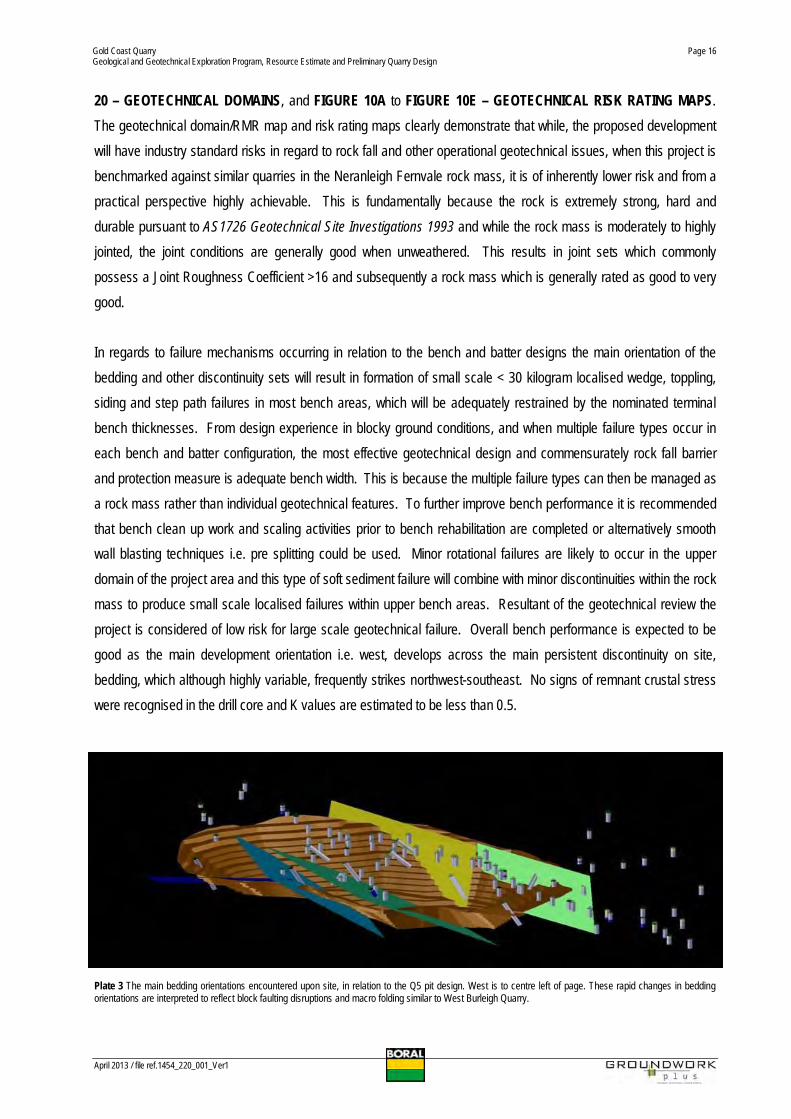
In regards to failure mechanisms occurring in relation to the bench and batter designs the main orientation of thebedding and other discontinuity sets will result in formation of small scale < 30 kilogram localised wedge, toppling,siding and step path failures in most bench areas, which will be adequately restrained by the nominated terminalbench thicknesses. From design experience in blocky ground conditions, and when multiple failure types occur ineach bench and batter configuration, the most effective geotechnical design and commensurately rock fall barrierand protection measure is adequate bench width. This is because the multiple failure types can then be managed asa rock mass rather than individual geotechnical features. To further improve bench performance it is recommendedthat bench clean up work and scaling activities prior to bench rehabilitation are completed or alternatively smoothwall blasting techniques i.e. pre splitting could be used. Minor rotational failures are likely to occur in the upperdomain of the project area and this type of soft sediment failure will combine with minor discontinuities within the rockmass to produce small scale localised failures within upper bench areas. Resultant of the geotechnical review theproject is considered of low risk for large scale geotechnical failure. Overall bench performance is expected to begood as the main development orientation i.e. west, develops across the main persistent discontinuity on site,bedding, which although highly variable, frequently strikes northwest-southeast. No signs of remnant crustal stresswere recognised in the drill core and K values are estimated to be less than 0.5.
Plate 3 The main bedding orientations encountered upon site, in relation to the Q5 pit design. West is to centre left of page. These rapid changes in beddingorientations are interpreted to reflect block faulting disruptions and macro folding similar to West Burleigh Quarry.

Gold Coast QuarryGeological and Geotechnical Exploration Program, Resource Estimate and Preliminary Quarry Design
April 2013 / file ref.1454_220_001_Ver1
Page 17
Rock Quality
Over the majority of the site a thin veneer of stony lithosols (residual soil profile) which is on average fifteen to thirtycentimetres thick covers the extremely weathered meta–greywacke. This residual soil profile is thicker in the gulliesand ravines of the site and at the toe of most slopes, however over the majority of the proposed extraction area, theresidual soil profile is relatively thin. Below the residual soil profile exists an extremely weathered meta–greywackeunit which is on average 0.7 m thick. This material is designated as overburden and may be suitable for use as fill forsite pad construction, or for the production of lower quality road bases i.e. QDTMR MRS 11.05 road base, subtype2.5 and general/lower quality engineered fills. The material between one to five metres depth if scalped, or otherwisebeneficiated, will be generally suitable for the production of most low to medium specification products i.e. QDTMRMRS 11.05 road base, subtypes 2.4 and 2.3, while generally below five metres vertical depth the main slightlyweathered to unweathered meta greywacke material will generally be capable of producing most high specificationconstruction materials including concrete and sealing aggregates, rail ballast, environmental revetment and armourrock and higher specification unbound pavement materials.
Plate 4 Drill hole GCQ2012_DDH005 0m to 5m depth. This core illustrates a typical intersection through the weathered profile of the rock mass which in thisinstance is four metres thick. Top left hand corner is the start of the hole while bottom right is at approximately five metres depth down hole or 4.3 metresvertically. The first metre of the core has little in the way of residual soil and is extremely weathered greywacke. Below the 1st metre the rock becomes morerecognisable as distinctly weathered greywacke. From approximately 3.4 metres depth the rock is considered to be a slightly weathered meta-greywacke rock.
Project Summary
In summary the proposed quarry design presented for the Gold Coast Quarry provides an excellent opportunity toutilise a strategically important quarry resource in an area which has a looming shortage of high quality constructionmaterials. The proposed quarry design clearly demonstrates that visual impacts on all adjacent receptors will bemanageable. Similarly the design seeks to mitigate noise and dust impacts by keeping major ridgelines between thequarry development and nearby residents. In regards to general environmental impacts and biodiversity values ofthe site, the key biodiversity hot spot has been avoided, as have the rare and endangered species occurring on thesite. In conclusion the proposed design highlights the fact that quarry development and subsequent rehabilitationworks and conservation efforts can be mutually inclusive and coexist.

Gold Coast QuarryGeological and Geotechnical Exploration Program, Resource Estimate and Preliminary Quarry Design
April 2013 / file ref.1454_220_001_Ver1
Page 18
1. IntroductionGroundwork Plus was commissioned by Cardno HRP and Boral Resources (Queensland) Pty Ltd to complete acomprehensive geological and geotechnical investigation for the proposed Gold Coast Quarry refer FIGURE 1 –SITE LOCATION PLAN. To complete this work and to gain an appreciation of the specific issues which couldpotentially impact upon the project, several site visits were undertaken in mid-2012. Resultant of these activities astaged quarry development plan was developed in conjunction with Boral senior technical management and withcognisance of relevant environmental constraints and impacts, current legislative requirements, and riskmanagement practices.
The geological and geotechnical work completed by Groundwork Plus follows the general outline provided by theCSIRO Guidelines for Open Pit Slope Design and for clarification of terminology used in this report all readers shouldreference this document as it is currently considered “leading practice” for geotechnical mine and slope design inAustralia. For resource reporting the Joint Ore Reserves Committee Guidelines on the reporting on ExplorationResults Mineral Resources and Ore Reserves has been complied with.
1.1 The Proponent
Boral Resources (Qld) Pty Limited, (Boral), a wholly owned subsidiary of Boral Limited, primarily serves customers inthe building and construction industries through the production and distribution of a broad range of constructionmaterials including quarry products, pre-mix concrete and asphalt.
Boral operates over one hundred sites across Queensland, including thirty quarries, forty-eight concrete batchingplants, and sixteen asphalt plants. The business is geographically diverse with operations in all major coastal centresfrom the Gold Coast to Cairns and westward as far as Barcaldine. Boral has held a key position supplyingconstruction materials across South East Queensland for a number of years with numerous quarries, concrete plantsand asphalt operations serving the infrastructure and construction markets from strategic locations, close to market,across the region.
1.2 The Project
Boral is seeking to establish a new extractive industry operation on a greenfield site at Tallebudgera Creek Road,near Reedy Creek on the Gold Coast. The project will activate a greenfield extractive resource that is recognisedunder State Planning Policy 2/07 – Protection of Extractive Resources as State Significant.
The project is necessary to compensate for the scheduled winding down of Boral’s existing West Burleigh Quarry,which has sufficient reserves for only a further 5 to 8 years of production. Given the lead times which are involved (ingaining development and environmental approvals; establishing the operation and completing preliminary site worksin order to enable full scale production), it is necessary for Boral to now commence the relevant approval processes

Gold Coast QuarryGeological and Geotechnical Exploration Program, Resource Estimate and Preliminary Quarry Design
April 2013 / file ref.1454_220_001_Ver1
Page 19
to ensure that an adequate, uninterrupted and efficient supply of construction materials remains available for criticalinfrastructure and construction projects in the Gold Coast region. The Gold Coast Quarry will represent aninvestment of $140 million by Boral into the economy of the Gold Coast region and is projected to provide duringconstruction total of 370 full time positions and continuity of employment for approximately 55 staff across Boral’sintegrated quarrying, asphalt, concrete and transport operations.
The site of the proposed Gold Coast Quarry contains a large deposit of meta-greywacke quarry rock resources.Meta greywacke is of extremely high strength and forms the excavated and processed quarry product. The meta-greywacke resource is located within a deposit that is favourably surrounded by ridgelines (reducing amenityimpacts) and has the benefit of having substantial vegetated buffers on land owned by Boral. In developing thisproposal, Boral has attempted to balance the need to secure this hard rock resource with the social andenvironmental factors of extractive industry development. Boral has voluntarily sterilised a significant proportion ofthe resource which is known to occur on the site in order to achieve an appropriate balance between environmental,economic and social interests.
The proposed development will operate as a quarry for the extraction and processing of hard rock primarily for use inconcrete, asphalt, drainage materials, road base, bricks, pavers, pipes and landscape supplies. Investigationsindicate that the quality and consistency of the resource at the site is of equal or better quality than themeta�greywacke deposit situated at Boral’s existing West Burleigh Quarry, providing an opportunity to completelyreplace the current operations at West Burleigh due to the diminishing supply of consented resources at that site.The proposed Gold Coast Quarry has the potential to supply the Gold Coast region with high grade constructionmaterials for in excess of 40 years whilst maintaining continuity of employment across Boral’s integrated quarrying,asphalt, concrete and transport operations. The greenfield site will be fully developed and operated in accordancewith recognised industry best practice.

Gold Coast QuarryGeological and Geotechnical Exploration Program, Resource Estimate and Preliminary Quarry Design
April 2013 / file ref.1454_220_001_Ver1
Page 20
1.3 The Site
The following table summarises the particulars of the site on which the Gold Coast Quarry is proposed.
SUMMARY OF SITE PARTICULARS
Street Address: Tallebudgera Creek Road, Tallebudgera Valley QLD 4228.RP Description: Lot 105 on SP144215; and Lot 901 on RP907357.Total Site Area: 219.998 ha.Local Government Area: Gold Coast City Council.SEQ Regional Plan 2009-2031 Designation: Urban Footprint.Local Government Planning:Scheme Designations:
Part Urban Residential Strategic Designation; Part Park LivingStrategic Designation; Part Open Space/Nature ConservationStrategic Designation; Emerging Communities Domain; ReedyCreek Structure Plan Area; Part Urban Residential StructurePlan Precinct; Part Park Living Structure Plan Precinct; andPart Open Space/Nature Conservation Structure PlanPrecinct.
Registered Proprietors: Boral Resources (Qld) Pty Limited; and Gold Coast CityCouncil (as trustee).
Environmental Constraints: Refer FIGURE 11 – ENVIRONMENTAL CONSTRAINTS.
1.3.1 Location and Contextual Setting
The site of the proposed Gold Coast Quarry is located on the western side of the Pacific Motorway, approximatelyfive kilometres from Burleigh Heads. Topographically, the site contains a number of gullies and vegetated ridgelines,with the resource being located within a central deposit that is favourably surrounded by ridges. The site is of a sizeand dimension which is sufficient to provide the rare opportunity for substantial vegetation buffer areas to bemaintained on land owned by Boral. The site consists of rugged hilly terrain in the west and north whilst the areas inthe south are of a more gentle relief and less incised nature. The north and western landforms are characterized bysteep slopes and gullies. The slopes of these upper flanks of the ridges are steep (circa 30º) while the lower flankslopes are generally moderately inclined (10-20º). Dominant soils are shallow stony lithosols and lithosol intergrades.
1.3.2 Site Area
The irregular shaped site contains a total site area of 219.998 hectares, including a 3.298 ha Council owned parklandallotment (Lot 901 on RP907357 and not used for quarrying) which traverses the site generally in a south east tonorth west direction between Tallebudgera Creek Road and Chesterfield Drive refer FIGURE 12 – SITE CADASTRE.

Gold Coast QuarryGeological and Geotechnical Exploration Program, Resource Estimate and Preliminary Quarry Design
April 2013 / file ref.1454_220_001_Ver1
Page 21
1.3.3 Current Use
The site, under the ownership of Boral (Lot 105 on SP144215) and the Gold Coast City Council (Lot 901 onRP907357), has a history of extensive clearing, grazing and other rural pursuits. At present, the site contains somesmall cleared areas (developed with nursery sheds, dams and access tracks) set amongst extensive areas ofregrowth vegetation and pockets of remnant vegetation, refer FIGURE 13 – AERIAL PHOTO AND TOPOGRAPHY.
1.3.4 Land Tenure and Native Title
Lot 105 on SP144215 is subject to freehold title and is not currently burdened or benefitted by any existingeasements. Lot 901 on RP907357 is a reserve administered by the Council of the City of Gold Coast as trustee. It isnot currently burdened or benefitted by existing easements. Native title has been extinguished over both allotmentswhich comprise the site.
1.3.5 Road Frontage and Vehicular Access
The site contains frontages to three constructed roads, Chesterfield Drive to the site’s north west, TallebudgeraCreek Road to the south and Old Coach Road to the east. Vehicular access will only be obtained to and from anominated point on Old Coach Road to be defined by Gold Coast City Council engineering requirements. Access toand from the site is proposed by Old Coach Road, which connects the site to the Pacific Motorway via an existinginterchange to the north. However, Boral understand that the Gold Coast City Council are currently investigating thedevelopment of a new road corridor, using parts of Old Coach Road, to link Tallebudgera Creek Road from beyondthe east of the site with the existing Bermuda Street / M1 Pacific Motorway interchange to the north of the site (the“future connection road”). While transportation will occur along the existing Old Coach Road, which is identified as a‘Transport Route’ under the SPP 2/07, it is preferred by Boral that, should the alternate future connection road beconstructed, transportation and access be taken from this new road alignment. Both access options are thereforeunder consideration at this point in time.
1.3.6 The Assessment Process
The State Development and Public Works Organisation Act 1971 (SDPWOA) provides the Coordinator General withthe discretionary power to declare a project as a Coordinated Project. The SDPWOA draws together a range ofpowers and functions used by the State to facilitate large scale projects, under the declaration as a ‘CoordinatedProject”. The declaration of a Coordinated Project is representative of the significance of a project to the locality,region or State, and takes account of the potential economic, environmental and procedural considerationsassociated with the development.
The declaration of a Coordinated Project is not a statement of the State Government’s support for the proposeddevelopment. Rather, the declaration of a Coordinated Project represents the State’s acknowledgement that thesignificance and/or complexity of a development project requires comprehensive assessment. The assessmentprocess is summarised in the Flowchart 3.1 as supplied by Cardno HRP.

Gold Coast QuarryGeological and Geotechnical Exploration Program, Resource Estimate and Preliminary Quarry Design
April 2013 / file ref.1454_220_001_Ver1
Page 22
1.4 Scope of Work
The scope of work provided is listed below as are the specific points within the Terms of Reference that this reportseeks to address to the satisfaction of the regulators, relevant advisory bodies and community and other interestedpersons or stakeholder groups.
1.4.1 The Design Brief
The design brief scoped on related Geotechnical and Resource Drilling Evaluation Consultancy services. At theoutset this work was done in close association with the Boral Resources Technical team and they have had a largedegree of input into the final outcome.
For the drilling program the required scope was:
· Defining the position of holes to provide the best data for geotechnical data collection relating to wall stability atthe site (input from Boral to explain existing drill data and composite outcome of program); Status complete.
· Locating holes such they will be used as a source of rock quality at the site to improve geological knowledge ofthe resource. Source rock testing will be undertaken on completion of the geotechnical logging and datacollection from the core. Site access will be controlled by topography; Status initially completed byGroundwork and finalised by Boral Resources.
· Collection of appropriate samples for testing of quarry product parameters to allow for geological modelling ofthe deposit; Status complete, refer Section 4 and APPENDIX 5.
· A staged geotechnical data collection program may be outlined for future improvement of the geotechnical andgeological models. Status complete and included in Section 5 of this report.
Gold Coast QuarryGeological and Geotechnical Exploration Program, Resource Estimate and Preliminary Quarry Design
April 2013 / file ref.1454_220_001_Ver1
Page 23
Responsibility for the project was defined as:· Finalise planning of hole locations by applying constraints that may apply to the location of the drill holes. Must
be in accordance with Boral's requirements and timing (estimated costs, potential variations to time and costshould be identified); Status completed initially by Groundwork however finalised by Boral Resources.
· Supervise the program including monitoring and reporting daily costs incurred during the program. A dailypresence at the drill rig during geotechnical drilling is required. Training of drilling crew and others may berequired to ensure geotechnical data is not compromised. Down hole surveys to be undertaken as is requiredand at varied intervals if needed to ensure core orientation is known; Status complete.
· Treat the core produced for geotechnical data gathering first, ensure logging of core also encompasses thesource rock logging. Ensure core is available quickly for source rock testing once geotechnical aspects are dealtwith; Status complete.
· Logging to be undertaken while drilling is underway to be sure no information is lost. Actions to remedy issuesmay be taken as required "On the run" using experience and technical support; Status complete.
· Once geotechnical data collection is completed gather rock quality information including dispatch of appropriatesamples to agreed lab; Status complete.
· Compile geological data; Status complete.· Undertake geotechnical interpretation of site, recommending design parameters of planned excavation footprint;
Status complete.· Create geological model of site and use surface mapping as appropriate; Status complete.· Model in hard copy and digital files for 3D mine planning (data to be compatible with Surpac and MapInfo
software). Status will be complete when report finalised via File Upload Facility.
Outputs for the project were defined as:· Report to Boral on geotechnical issues and design constraints; Status complete, refer Sections 5/6 of this
report.· Report to Boral on geological model for site; Status complete, refer Section 4 and Section 6 of this report.· 3D resource model in hard and digital format (compatible with Boral licensed software); Status complete.· Data datum's, AHD, MGA and GDA (94) coordinates must be in metres only (not degrees); Status complete.· Highlight major risks given development speed and outline possible options for further staged geotechnical and
geological resource model data collection being mindful of speed timing of development; and Status complete,refer Sections 4/5/6/7 of this report.
· Suggest ongoing monitoring programs and data collection from site to improve both models over time. Statuscomplete, refer Sections 6 and 7 of this report.
Gold Coast QuarryGeological and Geotechnical Exploration Program, Resource Estimate and Preliminary Quarry Design
April 2013 / file ref.1454_220_001_Ver1
Page 24
1.4.2 Terms of Reference
Salient points of this report which address the Terms of Reference (TOR) for the project are listed as follows:
· TOR Section 2.1 Overview of the project- Bullet Point 3 Description of the resource, including rates of extraction over time. Refer Executive Summary and Section 4.- Bullet Point 7 Description of development stages, including timeframes, of the project over its lifecycle. Refer Executive Summary, FIGURE 3 to FIGURE 7 and Section 4.
· TOR Section 2.4 Operation phase- Provide full details of the operation for all elements of the project, including drawings, maps and detailed plans, describing:
▫ Bullet Point 5 staging plan for works over the site throughout the life of the operations. ReferFIGURE 3 to FIGURE 7.
· TOR 3.2.2 Extractive resources- The EIS should provide a summary of the results of studies and surveys undertaken to identify and delineate the extractive resources within the project area. The location, volume/tonnage and quality/end product use of the extractive resources within the project area should be detailed. Refer
Section 4.· TOR 3.2.2 Potential impacts and mitigation measures
- The EIS should analyse the effectiveness of the project in achieving the optimum utilisation of the extractive resources and consider its impacts on other extractive resources. It should demonstrate that the proposal would ‘best develop’ the extractive resources within the project area, minimise resource wastage and avoid any unnecessary sterilisation. Refer Section 4.
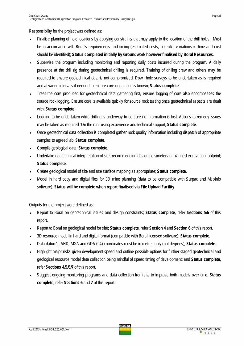
Plate 5 Bedding Planes and drill holes in relation to pit design.

Gold Coast QuarryGeological and Geotechnical Exploration Program, Resource Estimate and Preliminary Quarry Design
April 2013 / file ref.1454_220_001_Ver1
Page 25
2. Geology
2.1 Regional Geology
The regional geology of the site is described below which much of this information drawn from the work of Wilmottet.al and subsequently refined by Boral and its consultants, refer FIGURE 14 – REGIONAL GEOLOGY.
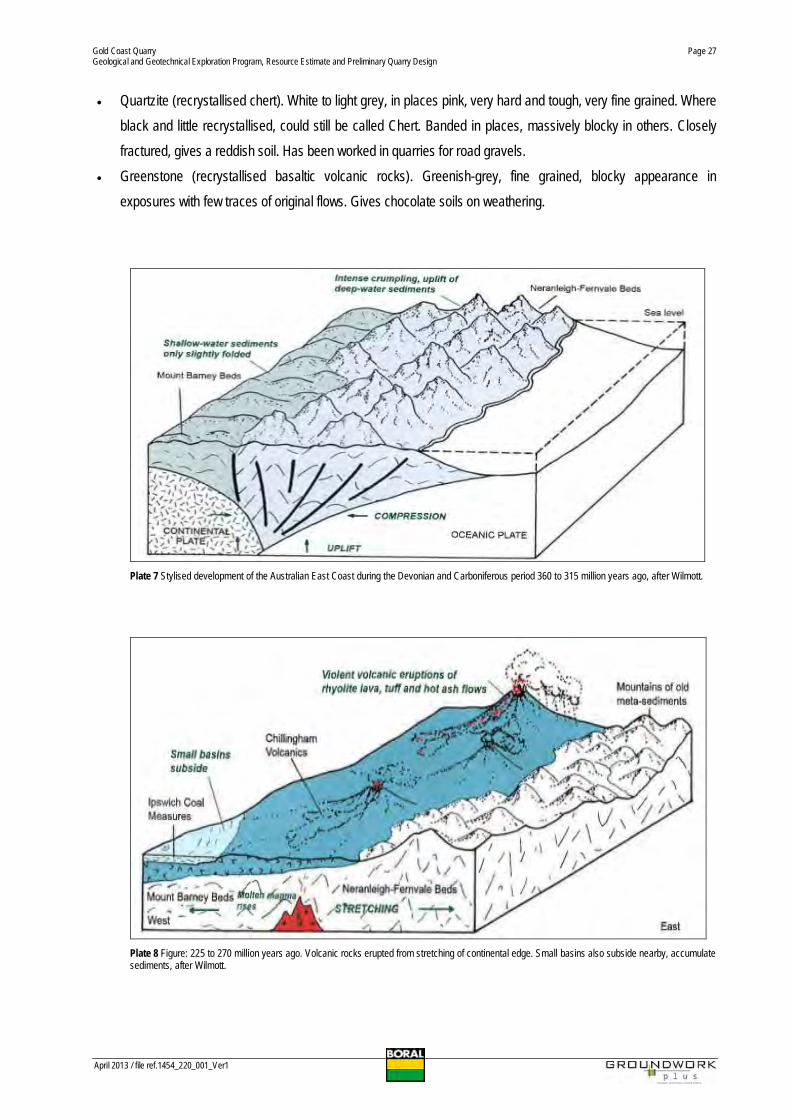
From about the end of the Devonian period throughout much of the succeeding Carboniferous, (360 to 315 millionyears ago), large volumes of sediments were eroded from the volcanic mountain chain. These were depositedinitially on the continental shelf and some remained there. The shelf edge was however steep, and from time to timethe accumulated sediments became unstable, and avalanched down canyons cut into continental slope in highly fluidturbid currents. These disgorged onto the deep ocean floor to form thick overlapping beds of sands, silts and muds.Some basalt lava flows were poured out onto the sea floor, and are included in the sequence. In places, patches ofchert (silica) built up, either from chemical precipitation of silica from sea water, or from gradual accumulation of thesiliceous skeletons of microscopic ocean-dwelling animals called radiolaria. This mixture of sediments and volcanicswas ‘scraped off’ when the ocean floor was subducted beneath the continent. It became hardened and converted torock by the action of pressure, heat and cementing agents such as silica.
Plate 6 Stylised development of the Australian East Coast during the Devonian and Carboniferous period 360 to 315 million years ago.
About 315 million years ago, near the end of the Carboniferous period, the deep-water sediments were compressedand crumpled from a squeezing together of the crustal plates after subduction ceased. They were folded (crumpled)and slightly recrystallised (or metamorphosed) to form steeply inclined strata of ‘meta-sedimentary’ rocks.Eventually, they were thrust up above sea level, probably to form high mountainous terrain. These rocks named the
Gold Coast QuarryGeological and Geotechnical Exploration Program, Resource Estimate and Preliminary Quarry Design
April 2013 / file ref.1454_220_001_Ver1
Page 26
Neranleigh-Fernvale Beds are now exposed on the site and form the high ridgeline to the immediate west of the GoldCoast. Similar rocks occur as far north as Yeppoon in central Queensland i.e. Beserker Beds and south to PortMacquarie in New South Wales i.e. the Mingaletta Block. Because of the paucity of life in the deep ocean and thesubsequent deformation, few fossils have been found in the greywackes.
Little is known about what became of the sediments deposited on the shallow continental shelf to the west, but theyare thought to be now hidden beneath younger sediments, Only in one place, around the foothills of Mount Barney,do they occur at the surface. There they have been dragged up when the intrusion of molten magma that formed thismountain, was forced upwards in much later times. These sediments are called the Mount Barney Beds, and theycontain fossils of organisms from a shallow water environment.
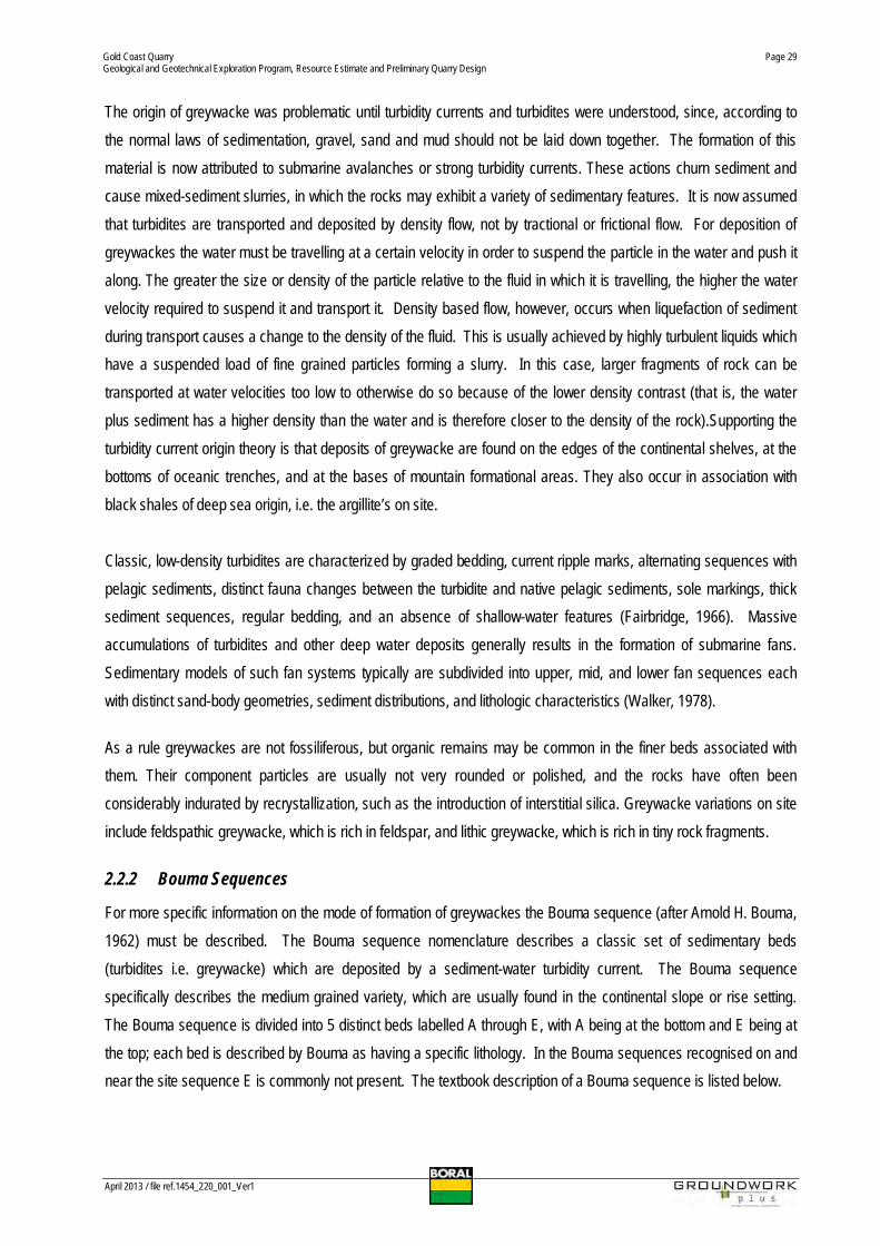
Towards the end of the Carboniferous period and extending into the early Permian (310 to 265 million years ago) theeastern edge of the continental plate relaxed and extended possibly as the subduction zone moved away to the east.Some volcanic rocks were erupted and sediments were deposited in small subsiding basins, but none of these arepreserved in the Gold Coast region. However, a second episode of stretching about 225 to 210 million years ago inthe late Triassic period, and the subsequent reduction in pressure in the still-hot lower crust, resulted in thegeneration of molten magma deep in the crust. This rose upwards to be erupted in violent volcanoes along thecontinental edge, and rocks from these are well represented in the Gold Coast hinterland. Various lavas, chieflyrhyolite, and fragmental rocks from explosions covered the western hills of the Neranleigh-Fernvale Beds. TheseChillingham Volcanics are now exposed between Tamborine Mountain, Canungra, and the Numinbah Valley but theyalso extend much further westward, deep beneath succeeding sediments. They are a complex sequence, now muchdisrupted and eroded, and the positions of the original volcanoes can no longer be recognised. They are similar tothe well known Brisbane Tuff, which has been quarried for building stone around Brisbane since the early days ofsettlement, and the North Arm Volcanics on the Sunshine Coast.
2.1.1 Main Rock Types of the Neranleigh Fernvale Beds
The four main rock types of the Neranleigh–Fernvale beds are listed below. They are hard, chiefly meta-sedimentaryrocks and greenstone which are now folded and generally steeply inclined:
· Argillite (hardened and slightly recrystallised mudstone or shale). Dark grey to black, very fine grained, beddingor banding commonly visible, grades into an inferior type of slate. Closely fractured in many exposures, givesshallow pale soils. Some slate has been used for decorative walls on the Gold Coast.
· Greywacke (hardened and slightly recrystallised coarse-grained sediment of mixed composition). Dark grey,hard, with grains of quartz and feldspar and fragments of other rocks. Large angular fragments of black shalefrom surrounding sediments common in places. Forms thick bands with few traces of individual beds, and whereexposed has a blocky appearance, gives shallow, pale, rocky soils. Important source of crushed rock aggregatefor construction uses.
Gold Coast QuarryGeological and Geotechnical Exploration Program, Resource Estimate and Preliminary Quarry Design
April 2013 / file ref.1454_220_001_Ver1
Page 27
· Quartzite (recrystallised chert). White to light grey, in places pink, very hard and tough, very fine grained. Whereblack and little recrystallised, could still be called Chert. Banded in places, massively blocky in others. Closelyfractured, gives a reddish soil. Has been worked in quarries for road gravels.
· Greenstone (recrystallised basaltic volcanic rocks). Greenish-grey, fine grained, blocky appearance inexposures with few traces of original flows. Gives chocolate soils on weathering.
Plate 7 Stylised development of the Australian East Coast during the Devonian and Carboniferous period 360 to 315 million years ago, after Wilmott.
Plate 8 Figure: 225 to 270 million years ago. Volcanic rocks erupted from stretching of continental edge. Small basins also subside nearby, accumulatesediments, after Wilmott.

Gold Coast QuarryGeological and Geotechnical Exploration Program, Resource Estimate and Preliminary Quarry Design
April 2013 / file ref.1454_220_001_Ver1
Page 28
Shortly after the volcanic episode of late Triassic times when the crust was still under tension, small basins subsidedadjacent to the volcanoes and among the mountains of the older meta-sediments. Streams flowing into thesegradually deposited shales, siltstones and sandstones on their floodplains – these are now the Ipswich CoalMeasures. There are only remnants in the Gold Coast hinterland, occurring at the surface in a narrow strip north ofTamborine Mountain and south of Canungra, but they are much thicker in Brisbane and Ipswich. There they containworkable coal seams, which formed from vegetation in swamps on the flood plains.
At the end of the Triassic period, the continental edge became much more stable, but sagged considerably in abroad area to the west of the coastal mountains – the Clarence-Moreton Basin and the Surat Basin. From the latestTriassic to the early Jurassic (210 to 180 million years ago) an extensive area was covered by sediments broughtdown by large stream systems. The first sediments were coarse sandstones and conglomerates of the WoogarooSubgroup – these overlapped the Ipswich Coal Measures and Chillingham Volcanics
2.2 Site Geology
The site geology is dominated by meta-greywacke rocks of the Neranleigh-Fernvale Beds refer FIGURE 15 – SITEGEOLOGY. This geological unit hosts the majority of extractive industry resources in the area. The principal rocktypes on the site are meta-greywacke and argillite and both rock types area variably exposed in subcrop andsporadic outcrop across the site. By volume Greywacke accounts for approximately 85-90% of the extractiveresource on site.
2.2.1 Meta-greywacke/Greywacke
Meta-greywacke is the principal rock type occurring over the bulk of the proposed extractive area and consistspredominantly of medium grained quartz-feldspar rich meta-greywacke with subordinate lithic fragments of meta-siltstone. The meta-greywacke generally exhibits a faint to readily discernible foliation. It is composed primarily offeldspar, quartz, sericite and epidote group minerals and is considered to be formed by mild deformation and partialrecyrstallisation of moderately sorted quartzo-feldspathic labile arkose. In hand specimen the meta-greywacke isgenerally massive, fine to medium grained and homogeneous, although both finer and coarser horizons do exist,especially in the west of the site where conglomerates and coarse grained greywacke were encountered.
In general terms, greywacke is a variety of sandstone generally characterized by its hardness, dark colour, andpoorly sorted angular grains of quartz, feldspar, and small rock fragments or lithic fragments set in a compact, clay-fine matrix and is considered a texturally immature sedimentary rock. The larger grains can be sand- to gravel-sized,and matrix materials generally constitute more than 15% of the rock by volume. The term "greywacke" can beconfusing, since it can refer to either the immature (rock fragment) aspect of the rock or the fine-grained (clay)component of the rock. The term greywacke is also a colloquial term and sensu stricto the rock should be called alithic arenite.
Gold Coast QuarryGeological and Geotechnical Exploration Program, Resource Estimate and Preliminary Quarry Design
April 2013 / file ref.1454_220_001_Ver1
Page 29
The origin of greywacke was problematic until turbidity currents and turbidites were understood, since, according tothe normal laws of sedimentation, gravel, sand and mud should not be laid down together. The formation of thismaterial is now attributed to submarine avalanches or strong turbidity currents. These actions churn sediment andcause mixed-sediment slurries, in which the rocks may exhibit a variety of sedimentary features. It is now assumedthat turbidites are transported and deposited by density flow, not by tractional or frictional flow. For deposition ofgreywackes the water must be travelling at a certain velocity in order to suspend the particle in the water and push italong. The greater the size or density of the particle relative to the fluid in which it is travelling, the higher the watervelocity required to suspend it and transport it. Density based flow, however, occurs when liquefaction of sedimentduring transport causes a change to the density of the fluid. This is usually achieved by highly turbulent liquids whichhave a suspended load of fine grained particles forming a slurry. In this case, larger fragments of rock can betransported at water velocities too low to otherwise do so because of the lower density contrast (that is, the waterplus sediment has a higher density than the water and is therefore closer to the density of the rock).Supporting theturbidity current origin theory is that deposits of greywacke are found on the edges of the continental shelves, at thebottoms of oceanic trenches, and at the bases of mountain formational areas. They also occur in association withblack shales of deep sea origin, i.e. the argillite’s on site.
Classic, low-density turbidites are characterized by graded bedding, current ripple marks, alternating sequences withpelagic sediments, distinct fauna changes between the turbidite and native pelagic sediments, sole markings, thicksediment sequences, regular bedding, and an absence of shallow-water features (Fairbridge, 1966). Massiveaccumulations of turbidites and other deep water deposits generally results in the formation of submarine fans.Sedimentary models of such fan systems typically are subdivided into upper, mid, and lower fan sequences eachwith distinct sand-body geometries, sediment distributions, and lithologic characteristics (Walker, 1978).
As a rule greywackes are not fossiliferous, but organic remains may be common in the finer beds associated withthem. Their component particles are usually not very rounded or polished, and the rocks have often beenconsiderably indurated by recrystallization, such as the introduction of interstitial silica. Greywacke variations on siteinclude feldspathic greywacke, which is rich in feldspar, and lithic greywacke, which is rich in tiny rock fragments.
2.2.2 Bouma Sequences
For more specific information on the mode of formation of greywackes the Bouma sequence (after Arnold H. Bouma,1962) must be described. The Bouma sequence nomenclature describes a classic set of sedimentary beds(turbidites i.e. greywacke) which are deposited by a sediment-water turbidity current. The Bouma sequencespecifically describes the medium grained variety, which are usually found in the continental slope or rise setting.The Bouma sequence is divided into 5 distinct beds labelled A through E, with A being at the bottom and E being atthe top; each bed is described by Bouma as having a specific lithology. In the Bouma sequences recognised on andnear the site sequence E is commonly not present. The textbook description of a Bouma sequence is listed below.

Gold Coast QuarryGeological and Geotechnical Exploration Program, Resource Estimate and Preliminary Quarry Design
April 2013 / file ref.1454_220_001_Ver1
Page 30
The beds are:
· E: Muds, ungraded, often bioturbated.· D: Parallel laminated silts.· C: Cross laminated sands.· B: Parallel laminated sands.· A: Sands and any larger grains the turbidity current was carrying at the time of deposition.
Plate 9 Typical Bouma Sequence.
Plate 10 Bouma sequence from core. Red is unit A, Blue is unit B, Yellow is C and sequence D and E is lime green before the cycle restarts.

Gold Coast QuarryGeological and Geotechnical Exploration Program, Resource Estimate and Preliminary Quarry Design
April 2013 / file ref.1454_220_001_Ver1
Page 31
The base of the greywacke, below A, is commonly scoured. Bouma cycles begin with an erosional contact of acoarse lower bed of pebble to granule conglomerate in a sandy matrix, and grade up through coarse then mediumplane parallel sandstone; through cross-bedded sandstone; rippled cross-bedded sand/silty sand, and finally laminarsiltstone and shale. This vertical succession of sedimentary structures, bedding, and changing lithology isrepresentative of strong to waning flow regime currents and their corresponding sedimentation. It is unusual to seeall of a complete Bouma cycle, as successive turbidity currents may erode the unconsolidated upper sequences.Alternatively, the entire sequence may not be present depending on whether the exposed section was at the edge ofthe turbidity current lobe (where it may be present as a thin deposit), or upslope from the deposition centre andmanifested as a scour channel filled with fine sands grading up into a pelagic ooze.
Plate 11 Coarse Grained Greywacke encountered in west of site in core hole GCQ2012_DDH_005 at 32 to 36 metres depth.
2.2.3 Meta-Siltstone/Argillite
Modest volumes of meta-siltstone/argillite occur in mainly the central southern and eastern sectors of the site, referFIGURE 15 – SITE GEOLOGY. These lithologies consists of dark grey to black, moderately fissile, carbonaceousmeta-siltstone and interbedded argillite with minor interbeds of fine grained meta-greywacke. Zones of silicifiedmeta-siltstone occur sporadically within these lithologies. The meta-siltstone and argillite lithologies are generallyconsidered to have lower strength and durability characteristics than the meta-greywacke lithologies and are likely tobe unsuitable for the manufacture of high strength concrete aggregates. The meta-siltstone is fine grained with amarked foliation. It has a mineralogical composition similar to the meta-greywacke but also contains minorcarbonaceous matter. It is considered to be formed by low grade metamorphism of labile siltstone.
Gold Coast QuarryGeological and Geotechnical Exploration Program, Resource Estimate and Preliminary Quarry Design
April 2013 / file ref.1454_220_001_Ver1
Page 32
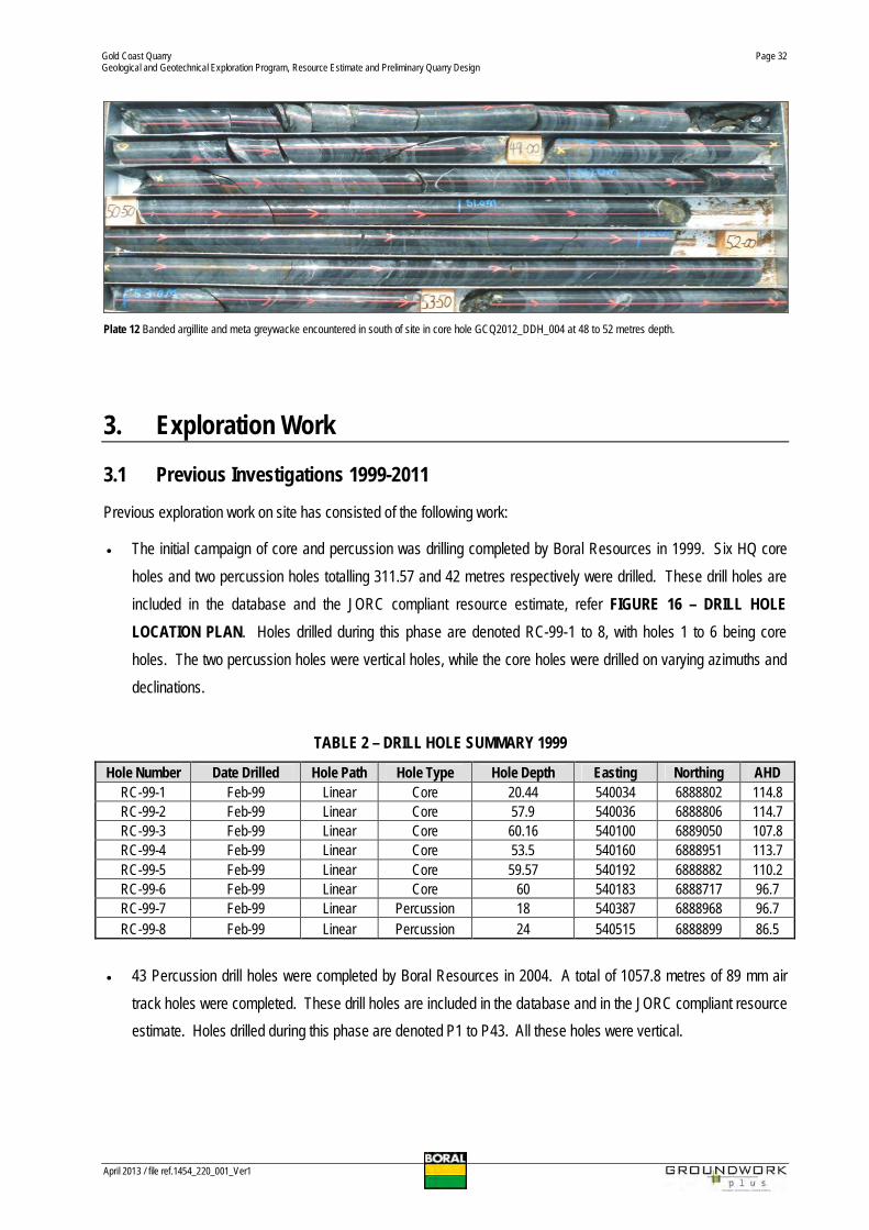
Plate 12 Banded argillite and meta greywacke encountered in south of site in core hole GCQ2012_DDH_004 at 48 to 52 metres depth.
3. Exploration Work
3.1 Previous Investigations 1999-2011
Previous exploration work on site has consisted of the following work:
· The initial campaign of core and percussion was drilling completed by Boral Resources in 1999. Six HQ coreholes and two percussion holes totalling 311.57 and 42 metres respectively were drilled. These drill holes areincluded in the database and the JORC compliant resource estimate, refer FIGURE 16 – DRILL HOLELOCATION PLAN. Holes drilled during this phase are denoted RC-99-1 to 8, with holes 1 to 6 being coreholes. The two percussion holes were vertical holes, while the core holes were drilled on varying azimuths anddeclinations.
TABLE 2 – DRILL HOLE SUMMARY 1999
Hole Number Date Drilled Hole Path Hole Type Hole Depth Easting Northing AHDRC-99-1 Feb-99 Linear Core 20.44 540034 6888802 114.8RC-99-2 Feb-99 Linear Core 57.9 540036 6888806 114.7RC-99-3 Feb-99 Linear Core 60.16 540100 6889050 107.8RC-99-4 Feb-99 Linear Core 53.5 540160 6888951 113.7RC-99-5 Feb-99 Linear Core 59.57 540192 6888882 110.2RC-99-6 Feb-99 Linear Core 60 540183 6888717 96.7RC-99-7 Feb-99 Linear Percussion 18 540387 6888968 96.7RC-99-8 Feb-99 Linear Percussion 24 540515 6888899 86.5
· 43 Percussion drill holes were completed by Boral Resources in 2004. A total of 1057.8 metres of 89 mm airtrack holes were completed. These drill holes are included in the database and in the JORC compliant resourceestimate. Holes drilled during this phase are denoted P1 to P43. All these holes were vertical.

Gold Coast QuarryGeological and Geotechnical Exploration Program, Resource Estimate and Preliminary Quarry Design
April 2013 / file ref.1454_220_001_Ver1
Page 33
TABLE 3 – DRILL HOLE SUMMARY 2004
Hole Number Date Drilled Hole Path Hole Type Hole Depth Easting Northing AHDP01 Jun-04 Linear Percussion 24.6 540405 6888966 94.3P02 Jun-04 Linear Percussion 24.6 540435 6888943 93.5P03 Jun-04 Linear Percussion 24.6 540481 6888925 86.5P04 Jun-04 Linear Percussion 24.6 540521 6888899 86.2P05 Jun-04 Linear Percussion 24.6 540569 6888896 79.4P06 Jun-04 Linear Percussion 24.6 540606 6888893 74P07 Jun-04 Linear Percussion 24.6 540655 6888899 68.2P08 Jun-04 Linear Percussion 24.6 540703 6888894 63.5P09 Jun-04 Linear Percussion 24.6 540749 6888903 58.04P10 Jun-04 Linear Percussion 24.6 540826 6888915 57.4P11 Jun-04 Linear Percussion 24.6 540862 6888908 55.7P12 Jun-04 Linear Percussion 24.6 540901 6888891 51.05P13 Jun-04 Linear Percussion 24.6 540964 6888892 36.2P14 Jun-04 Linear Percussion 24.6 540354 6888981 98.3P15 Jun-04 Linear Percussion 24.6 540300 6888999 100.4P16 Jun-04 Linear Percussion 24.6 540264 6889013 98.715P17 Jun-04 Linear Percussion 24.6 540326 6889042 92.4
Hole Number Date Drilled Hole Path Hole Type Hole Depth Easting Northing AHDP18 Jun-04 Linear Percussion 24.6 540216 6889028 99.6P19 Jun-04 Linear Percussion 24.6 540149 6889009 109.16P20 Jun-04 Linear Percussion 24.6 540095 6888948 114.77P21 Jun-04 Linear Percussion 24.6 540165 6888935 113.5P22 Jun-04 Linear Percussion 24.6 540121 6888915 113.1P23 Jun-04 Linear Percussion 24.6 540078 6888890 114.8P24 Jun-04 Linear Percussion 24.6 540051 6888870 119.5P25 Jun-04 Linear Percussion 24.6 540045 6888834 117.7P26 Jun-04 Linear Percussion 24.6 540212 6888947 108.2P27 Jun-04 Linear Percussion 24.6 540264 6888953 101.55P28 Jun-04 Linear Percussion 24.6 540310 6888955 99.25P29 Jun-04 Linear Percussion 24.6 540347 6888965 99.34P30 Jun-04 Linear Percussion 24.6 540056 6888916 118.1P31 Jun-04 Linear Percussion 24.6 540007 6888920 123.5P32 Jun-04 Linear Percussion 24.6 539964 6888902 128.8P33 Jun-04 Linear Percussion 24.6 540190 6888899 111P34 Jun-04 Linear Percussion 24.6 540204 6888853 108.1P35 Jun-04 Linear Percussion 24.6 540204 6888821 105.6P36 Jun-04 Linear Percussion 24.6 540199 6888767 101.5P37 Jun-04 Linear Percussion 24.6 540182 6888730 98.1P38 Jun-04 Linear Percussion 24.6 540192 6888702 95.1P39 Jun-04 Linear Percussion 24.6 540241 6888746 95.6P40 Jun-04 Linear Percussion 24.6 540277 6888710 89.85P41 Jun-04 Linear Percussion 24.6 540309 6888700 83.9P42 Jun-04 Linear Percussion 24.6 540466 6888880 94.7P43 Jun-04 Linear Percussion 24.6 540753 6888848 42.9

Gold Coast QuarryGeological and Geotechnical Exploration Program, Resource Estimate and Preliminary Quarry Design
April 2013 / file ref.1454_220_001_Ver1
Page 34
· A second campaign of core drilling was completed by Boral Resources in 2005. Three core holes totalling 197.4metres of un-orientated core were drilled. Core from this work was despatched for petrological analysis andalso materials testing work, refer APPENDIX 1 and APPENDIX 2. These drill holes are included in the databaseand in the JORC compliant resource estimate. These core holes were drilled at declinations of 60 degrees withazimuths ranging between northeast and east. RC-05-DDH01 to 03.
TABLE 4 – DRILL HOLE SUMMARY 2005 CORE DRILLING
Hole Number Date Drilled Hole Path Hole Type Hole Depth Easting Northing AHDRC05_DDH01 Feb-05 Linear Core 67.7 540350 6888884 77.5RC05_DDH02 Feb-05 Linear Core 59.73 540136 6888797 93.3RC05_DDH03 Feb-05 Linear Core 70 540562 6888777 84.2
· 6 piezometric holes were also completed in mid 2012 and have also been included in the database, denotedGCQ_Piezo_2012_01 to 06.
TABLE 5 – DRILL HOLE SUMMARY 2012 PIEZOMETER DRILLING
Hole NumberDate
Drilled Hole Path Hole Type Hole Depth Easting Northing AHDGCQ_Piezo_2012_01 8-08-12 Linear Percussion 17.2 540567 6889203 65GCQ_Piezo_2012_02 13-08-12 Linear Percussion 6.6 541160 6889117 16.3GCQ_Piezo_2012_03 13-08-12 Linear Percussion 25.2 541160 6889118 16.3GCQ_Piezo_2012_04 13-08-12 Linear Percussion 26.5 540286 6889537 33.7GCQ_Piezo_2012_05 13-08-12 Linear Percussion 6.6 540286 6889538 33.5GCQ_Piezo_2012_06 13-08-12 Linear Percussion 22 540382 6888966 96.7GCQ_Piezo_2012_07 13-08-12 Linear Percussion 19 539878 6888945 133.1
Resultant of this work concept pit designs were competed which delineated potential resources on the site rangingbetween 70 and 90 million tonnes. These resource estimates were completed for internal commercial purposes.
3.2 2012 Exploration Campaign
In 2012 a large drilling program consisting of 43 percussion holes and five deeper core holes was completed. Thiswork was targeted at primarily updating the geological and geotechnical model for the site. The percussion drillingtotalled 1014.8 metres of 89mm air track holes and was completed by Boral. The report prepared on this drilling isincluded as APPENDIX 3. The core drilling program was designed and managed by Boral Resources however waslogged both geotechnically and geologically by both Boral Resources and Groundwork Plus. The core holes startedas HQ diameter holes and generally reduced to NQ diameter holes at around 12 metres depth. A total of 491.5metres of core was drilled in this campaign, refer FIGURE 16 – DRILL HOLE LOCATION PLAN. This core was alsogenerally orientated utilising the OriShot electronic orientation system.
Gold Coast QuarryGeological and Geotechnical Exploration Program, Resource Estimate and Preliminary Quarry Design
April 2013 / file ref.1454_220_001_Ver1
Page 35
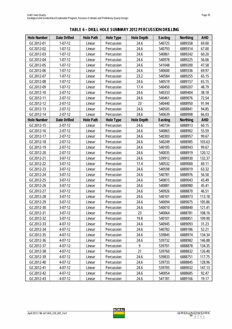
TABLE 6 – DRILL HOLE SUMMARY 2012 PERCUSSION DRILLING
Hole Number Date Drilled Hole Path Hole Type Hole Depth Easting Northing AHDGC2012-01 1-07-12 Linear Percussion 24.6 540725 6889358 69.00GC2012-02 1-07-12 Linear Percussion 24.6 540793 6889314 67.00GC2012-03 1-07-12 Linear Percussion 24.6 540861 6889242 60.20GC2012-04 1-07-12 Linear Percussion 24.6 540978 6889225 56.06GC2012-05 1-07-12 Linear Percussion 24.6 541048 6889200 47.58GC2012-06 1-07-12 Linear Percussion 24.6 540600 6889336 69.97GC2012-07 1-07-12 Linear Percussion 23.2 540584 6889255 65.15GC2012-08 1-07-12 Linear Percussion 24.6 540519 6889157 65.15GC2012-09 1-07-12 Linear Percussion 17.4 540450 6889207 48.79GC2012-10 2-07-12 Linear Percussion 24.6 540333 6889404 38.18GC2012-11 2-07-12 Linear Percussion 24.6 540461 6889076 72.54GC2012-12 2-07-12 Linear Percussion 23 540440 6888950 91.94GC2012-13 2-07-12 Linear Percussion 24.6 540505 6888841 94.85GC2012-14 2-07-12 Linear Percussion 24.6 540639 6888908 66.03
Hole Number Date Drilled Hole Path Hole Type Hole Depth Easting Northing AHDGC2012-15 2-07-12 Linear Percussion 24.6 540734 6888913 60.15GC2012-16 2-07-12 Linear Percussion 24.6 540865 6888902 55.59GC2012-17 2-07-12 Linear Percussion 24.6 540303 6888957 99.67GC2012-18 2-07-12 Linear Percussion 24.6 540249 6888985 103.63GC2012-19 2-07-12 Linear Percussion 24.6 540185 6888943 99.67GC2012-20 2-07-12 Linear Percussion 24.6 540035 6888919 120.12GC2012-21 3-07-12 Linear Percussion 24.6 539912 6888930 132.37GC2012-22 3-07-12 Linear Percussion 17.4 540532 6889000 69.11GC2012-23 3-07-12 Linear Percussion 24.6 540598 6889019 63.32GC2012-24 3-07-12 Linear Percussion 24.6 540781 6888976 56.50GC2012-25 3-07-12 Linear Percussion 24.6 540815 6889043 43.49GC2012-26 3-07-12 Linear Percussion 24.6 540881 6888980 45.41GC2012-27 3-07-12 Linear Percussion 24.6 540926 6888870 46.51GC2012-28 3-07-12 Linear Percussion 24.6 540101 6888973 113.18GC2012-29 3-07-12 Linear Percussion 24.6 540094 6889075 105.86GC2012-30 3-07-12 Linear Percussion 24.6 540010 6888840 121.41GC2012-31 3-07-12 Linear Percussion 23 540064 6888781 108.16GC2012-32 3-07-12 Linear Percussion 19.8 540101 6888851 109.90GC2012-33 4-07-12 Linear Percussion 24.6 540945 6889093 31.23GC2012-34 4-07-12 Linear Percussion 24.6 540782 6889186 52.21GC2012-35 4-07-12 Linear Percussion 24.6 539845 6888974 134.34GC2012-36 4-07-12 Linear Percussion 24.6 539732 6888982 146.88GC2012-37 4-07-12 Linear Percussion 9 539701 6888878 134.35GC2012-38 4-07-12 Linear Percussion 21 539760 6888832 126.40GC2012-39 4-07-12 Linear Percussion 24.6 539833 6888751 117.75GC2012-40 4-07-12 Linear Percussion 24.6 539733 6888845 128.96GC2012-41 4-07-12 Linear Percussion 24.6 539705 6889032 147.13GC2012-42 4-07-12 Linear Percussion 24.6 540054 6888685 92.47GC2012-43 4-07-12 Linear Percussion 24.6 541181 6889166 19.17

Gold Coast QuarryGeological and Geotechnical Exploration Program, Resource Estimate and Preliminary Quarry Design
April 2013 / file ref.1454_220_001_Ver1
Page 36
TABLE 7 – DRILL HOLE SUMMARY 2012 CORE DRILLING
Hole NumberDate
Drilled Hole Path Hole Type Hole Depth Easting Northing AHDGCQ2012_DDH001 3-08-12 Linear Core 126 540094 6889052 107.5GCQ2012_DDH002 6-09-12 Linear Core 120 540064 6888701 93.4GCQ2012_DDH003 17-09-12 Linear Core 65.5 540458 6889056 73.6GCQ2012_DDH004 20-09-12 Linear Core 60 540282 6888687 88.15GCQ2012_DDH005 27-09-12 Linear Core 120 539880 6888610 106.3
4. Results of Geological Investigations
4.1 Drill Results
The resource estimate is based on the results returned from the four different drilling campaigns as completed byBoral Resources and others. All material encountered was geologically logged pursuant to Australian StandardAS1726-1993: Geotechnical Site Investigations. Estimated material strength, hardness, degree of weathering,degree of alteration, rock structure, foliation intensity, and general rock type were recorded and then reviewed foraccuracy and consistency by Groundwork. The drill-hole locations are shown in FIGURE 16 – DRILL HOLELOCATION PLAN. The percussion drill hole logs are attached in APPENDIX 4 – 2012 DRILL HOLEPHOTOGRAPHS AND LOGS. Selected oblique sections have been developed across the site which displays thegeology of the site and also the depth of the weathering profile across the site. In some instances due to the20 m +/- tolerance used for sectional development minor inconsistencies appear in two dimensions which arehowever resolved in three dimensions by generation of a surface which is clipped to the base of each weatheringunit, refer FIGURE 17A FIGURE 17E – CROSS SECTIONS.
4.1.1 Core Orientations
For core orientations, each run in so far as is practical, was orientated and then linked with other orientations toconfirm the validity or otherwise of the orientation. To assess the individual accuracy of each orientation it was linkedwith nearby orientations which appeared correct, to determine overall individual orientation accuracy. In someinstances if the orientations were clearly erroneous, which happened on less than 8% of occasions, then theseorientations were recorded on the field logging sheet +/-core as being erroneous. Similarly when good orientationswere encountered, they were recorded on the field sheet, +/- the core. If small variations in orientation marks werenoted these were also recorded and then assessed forward and back to determine accuracy.
Importantly for the drilling program the first two holes are marked up with orientations lines on the top of the hole in
white marker while holes 3 to 5 are marked in permanent red markers denoting the bottom of hole. Alpha (a) and
Beta (b) angles were then recorded for bedding, veining and other structures especially notable shears when
encountered. In general terms the quality of the orientation work was very good below approximately 15m depth.

Gold Coast QuarryGeological and Geotechnical Exploration Program, Resource Estimate and Preliminary Quarry Design
April 2013 / file ref.1454_220_001_Ver1
Page 37
Once collected orientations were transformed utilising the Holcombe Geo-calculator to determine structuralrelationships in real space.
Plate 13 Orientation mark-ups GCQ2012 Holes 1 and 2 example.
Plate 14 Orientation mark-ups GCQ2012 Holes 3 to 5 example.
Drillers breaks were generally marked in white for holes 1 to 2 as completed by Boral Resources or yellow for holes 3to 5 as completed by Groundwork Plus. Metre marks for holes three to five were completed in blue paint. Examplesof both are provided in Plate 13 and 14 respectively. To further increase the accuracy and validity of the resourcework all old core holes were also scan relogged where drill cores were still available.
The investigations identified significant resources of meta-greywacke, which in a fresh to slightly weathered state,was hard, strong and durable. It was occasionally thinly interbedded with carbonaceous meta-siltstone and/orcontained occasional small clasts of meta-siltstone. The total of volume of argillite within the rock mass is estimatedto be around 15% of the total rock mass.
The depth of degree of weathering was found to be variable across the site, and is graphically represented inIsopach Maps FIGURES 18A to 18C.

Gold Coast QuarryGeological and Geotechnical Exploration Program, Resource Estimate and Preliminary Quarry Design
April 2013 / file ref.1454_220_001_Ver1
Page 38
4.2 Petrology
Seven samples have been collected previously by Boral which have been reviewed for mineralogical andpetrographic analysis. This petrographic analysis report can be found in APPENDIX 1 – GEOCHEMPETPETROGRAPHIC REPORTS. Five of the samples analysed greywacke variants, two of the coarse grained varietyand three of the fine grained variety, while two of the samples analysed argillite.
In summary the results of the petrology on the rock indicate that for engineering purposes, the main meta-greywackeresource on site may be summarised as:
· hard;· strong;· durable;· finely re-crystallised;· non-porous;· essentially unweathered;· lightly altered;· variable secondary mineral content ranging between 10 and 30%; and· the rock is predicted to be suitable for use as most high specification quarry products including unbound
pavement materials, asphalt and concrete aggregates.
For engineering purposes the meta-greywacke when unweathered is interpreted to be hard, durable and of high orvery high strength.
In regard to the quality of the meta argillite rocks on site this rock type is generally less suitable for use as highspecification construction materials, however it will readily blend in with the meta greywacke resource and in someinstances will actually improve the Atterberg characteristics of road base materials by increasing the plasticity andliquid limits of the road construction materials.
For engineering purposes the argillite is not recommended to be used for manufacture of durable products as itcontains elevated volumes of soft minerals including sericite and carbonaceous material. Additionally these rocktypes will preferentially part along the cleavage planes. That said the test results from the argillite show compliancewith higher specification requirements.
4.3 Material Testwork Results
A program of laboratory testing was carried out on bulk drill core samples to assess the suitability of the rock for themanufacture of quarried products.
Gold Coast QuarryGeological and Geotechnical Exploration Program, Resource Estimate and Preliminary Quarry Design
April 2013 / file ref.1454_220_001_Ver1
Page 39
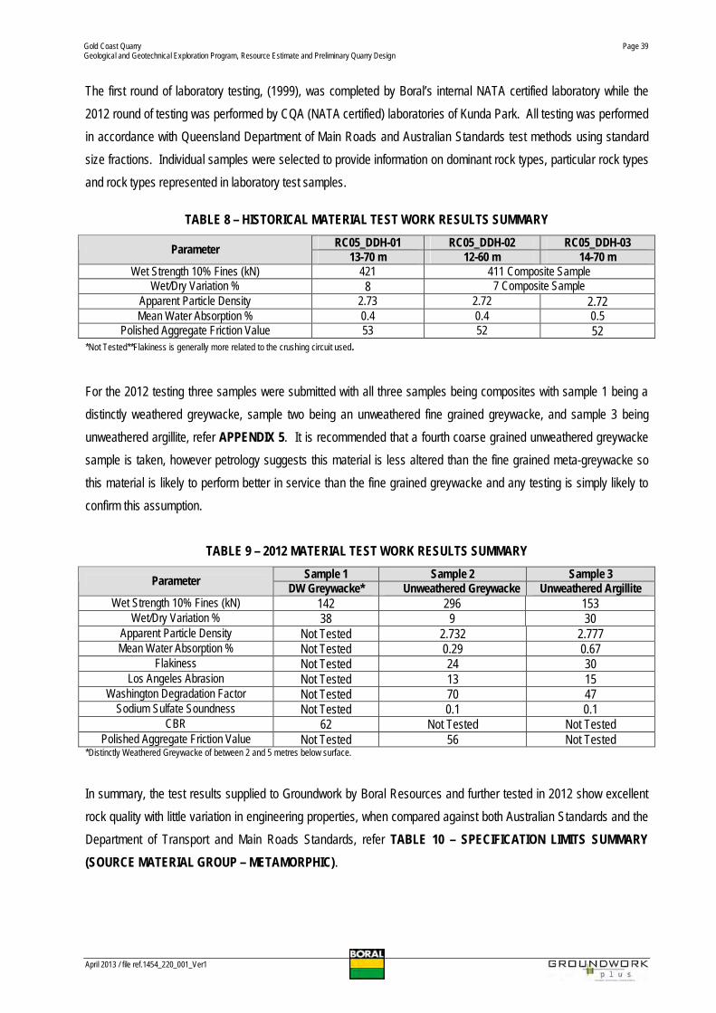
The first round of laboratory testing, (1999), was completed by Boral’s internal NATA certified laboratory while the2012 round of testing was performed by CQA (NATA certified) laboratories of Kunda Park. All testing was performedin accordance with Queensland Department of Main Roads and Australian Standards test methods using standardsize fractions. Individual samples were selected to provide information on dominant rock types, particular rock typesand rock types represented in laboratory test samples.
TABLE 8 – HISTORICAL MATERIAL TEST WORK RESULTS SUMMARYRC05_DDH-01 RC05_DDH-02 RC05_DDH-03Parameter 13-70 m 12-60 m 14-70 m
Wet Strength 10% Fines (kN) 421 411 Composite SampleWet/Dry Variation % 8 7 Composite Sample
Apparent Particle Density 2.73 2.72 2.72Mean Water Absorption % 0.4 0.4 0.5
Polished Aggregate Friction Value 53 52 52*Not Tested**Flakiness is generally more related to the crushing circuit used.
For the 2012 testing three samples were submitted with all three samples being composites with sample 1 being adistinctly weathered greywacke, sample two being an unweathered fine grained greywacke, and sample 3 beingunweathered argillite, refer APPENDIX 5. It is recommended that a fourth coarse grained unweathered greywackesample is taken, however petrology suggests this material is less altered than the fine grained meta-greywacke sothis material is likely to perform better in service than the fine grained greywacke and any testing is simply likely toconfirm this assumption.
TABLE 9 – 2012 MATERIAL TEST WORK RESULTS SUMMARYSample 1 Sample 2 Sample 3Parameter DW Greywacke* Unweathered Greywacke Unweathered Argillite
Wet Strength 10% Fines (kN) 142 296 153Wet/Dry Variation % 38 9 30
Apparent Particle Density Not Tested 2.732 2.777Mean Water Absorption % Not Tested 0.29 0.67
Flakiness Not Tested 24 30Los Angeles Abrasion Not Tested 13 15
Washington Degradation Factor Not Tested 70 47Sodium Sulfate Soundness Not Tested 0.1 0.1
CBR 62 Not Tested Not TestedPolished Aggregate Friction Value Not Tested 56 Not Tested
*Distinctly Weathered Greywacke of between 2 and 5 metres below surface.
In summary, the test results supplied to Groundwork by Boral Resources and further tested in 2012 show excellentrock quality with little variation in engineering properties, when compared against both Australian Standards and theDepartment of Transport and Main Roads Standards, refer TABLE 10 – SPECIFICATION LIMITS SUMMARY(SOURCE MATERIAL GROUP – METAMORPHIC).

Gold Coast QuarryGeological and Geotechnical Exploration Program, Resource Estimate and Preliminary Quarry Design
April 2013 / file ref.1454_220_001_Ver1
Page 40
TABLE 10 – SPECIFICATION LIMITS SUMMARY (SOURCE MATERIAL GROUP – METAMORPHIC)AUTHORITY/SPECIFICATION
QUEENSLAND DEPARTMENT OF TRANSPORT AND MAIN ROADS QUEENSLAND RAIL AUSTRALIANSTANDARD
UNBOUND PAVEMENT MATERIALS(TMRS 11.05 – 12/99)
COVER AGGREGATES(TMRS 11.22 – 12/99) RAILWAY BALLAST
(CT.147)CONCRETE AGGREGATES
(AS 2758-1 1998)
SUB TYPE CATEGORY TYPE EXPOSURE CLASSIFICATION
PROPERTY
1.1 1.2 2.1 2.2 2.3 2.4 2.5 A B C D
ASPHALTAGGREGATES(TMRS 11.30-
12/99)
CONCRETEAGGREGATES(TMRS 11.70-
12/99)
1 2 3 A1, A2 B1, B2 C10% Fines Wet Strength 140 105 125 105 90 80 - 175 150 100 100 150 120 160 140 120 50 80 100(kN minimum) *See Note 1 *See Note 1 *See Note 2Wet/Dry Strength Variation(% maximum) 35 40 35 35 40 40 - 30 35 40 40 35
*See Note 135
*See Note 2 35 35 35 45 35 25
Degradation Factor 45 35 45 45 35 35 - 40 45 40 35(% minimum) *See Note 1
Refer Section 9.3.4 of AS 2758.1-1998
Flakiness Index(% maximum) 35 35 35 35 40 40 - 30 35 35 35 35 30
CBR (Soaked)(Minimum) - - 80 60 45 35 15
Liquid Limit (LL) (% maximum) 25 28 25 25 28 35 40
Plasticity Index (PI)(% maximum) 4 6 6 6 8 12 14
Linear Shrinkage (LS)(% maximum) 2.5 3 3.5 3.5 4.5 6.5 7.5
PI x % passing 0.425 mm(maximum) - - 150 150 200 360 -
LS x % passing 0.425 mm(maximum) - - 85 85 110 195 -
Ratio0.075 mm/0.425 mm
MinMax
0.3-0.55
0.3-0.55
0.3-0.55
0.3-0.65
0.3-0.65 - -
Bulk Particle Density(t/m³ minimum) 2.60 2.55 2.5 2.1 2.1 2.1
Water Absorption(% maximum) 2 2.5 2 2 2 £ 2.0 £ 2.0 £ 2.0
Polished Aggregate FrictionValue (minimum) 45
Crushed Faces(% minimum) 70 70 80 80 80 N/A 80
Alkali Reactive Materials Refer AS 2758.1and Clause 10.1
of MRS 11.70Refer AS 2758.1 - 1998
Coarse grained 40 35 35Los Angeles Value (% lossmaximum) All other rocks 35 30 30Sodium sulfate soundness (maxweighted average loss) 12 9 6
Gold Coast QuarryGeological and Geotechnical Exploration Program, Resource Estimate and Preliminary Quarry Design
April 2013 / file ref.1454_220_001_Ver1
Page 41
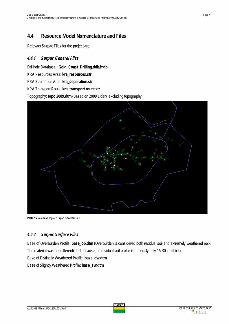
4.4 Resource Model Nomenclature and Files
Relevant Surpac Files for the project are:
4.4.1 Surpac General Files
Drillhole Database : Gold_Coast_Drilling.ddb/mdbKRA Resources Area: kra_resources.strKRA Separation Area: kra_separation.strKRA Transport Route: kra_transport route.strTopography: topo 2009.dtm (Based on 2009 Lidar) excluding topography
Plate 15 Screen dump of Surpac General Files.
4.4.2 Surpac Surface Files
Base of Overburden Profile: base_ob.dtm (Overburden is considered both residual soil and extremely weathered rock.The material was not differentiated because the residual soil profile is generally only 15-30 cm thick).Base of Distinctly Weathered Profile: base_dw.dtmBase of Slightly Weathered Profile: base_sw.dtm

Gold Coast QuarryGeological and Geotechnical Exploration Program, Resource Estimate and Preliminary Quarry Design
April 2013 / file ref.1454_220_001_Ver1
Page 42
Plate 16 Surpac Weathering Files with blue = overburden, light blue = distinctly weathered and green = slightly weathered. Because of the generally limitedweathering profiles on site. Visually the files are not overly useful however they have been used to constrain volumes in the block model. Brown is the Q5 pit designon an oblique angle. Vertical Exaggeration x 2.
4.4.3 Block Model Files
Gold Coast Block Model: 1454_model.mdlBlock Model Summary and Attributes x 12 including Lithology, Weathering, Wet Strength at 10% fines, WaterAbsorption, CBR, Apparent Particle Density, Flakiness, Los Angeles Abrasion, Sodium Sulfate Soundness, WashingtonDegradation Factor, Polished Aggregate Friction Value and Wet/Dry Strength % Variation.
Plate 17 Block Model Attributes

Gold Coast QuarryGeological and Geotechnical Exploration Program, Resource Estimate and Preliminary Quarry Design
April 2013 / file ref.1454_220_001_Ver1
Page 43
Plate 18 Section of Block Model with drilling and Q5 pit design in brown. Green blocks denote unweathered greywacke and as per previous plates grey denotesgreywacke intersections in drill holes. The three weathering surfaces are shown in yellow blue and red.
Plate 19 Section of Block Model with drilling and Q2 pit design in yellow and Q5 pit design in brown. Green blocks denote unweathered greywacke and as perprevious plates grey denotes greywacke intersections in drill holes.
A variety of constraints files have been produced, which relate to generation of volumes constrained by particularweathering surfaces. These files are included as APPENDIX 8 – DIGITAL DATA.

Gold Coast QuarryGeological and Geotechnical Exploration Program, Resource Estimate and Preliminary Quarry Design
April 2013 / file ref.1454_220_001_Ver1
Page 44
4.5 Geology Model
A 3D block model was constructed for the resource for the purposes of defining volumetric totals for each weatheringclass within the defined development plan. Block model development was completed using Surpac Mining Software.
A series of variables were incorporated into the block model for recording attributes assigned throughout developmentof the block model. The coding was assigned on the basis of the topographical, weathering class, and developmentplan wireframes.
Geological mapping and drilling campaigns have assisted in defining the nature and extent of rock resources at the siteand from this work an adequate appreciation of rock resources was obtained.
The following estimates of exploitable rock resources at the site are based primarily on available geological data, allborehole data, and a considered final development plan for the quarry taking potential constraints which may affect theproject into consideration.
It should be noted that lithological, structural and weathering characteristics of rock deposits such as those which occurat this site are variable and may change over relatively short distances both laterally and with depth. Data interpretationhas required certain assumptions to be made and development planning has required adoption of certain operationalparameters which could be subject to change as quarrying progresses.
4.6 Depth of Weathering
The weathering profile of the resource has been modelled in three dimensions, using Surpac mining software, based ondrill hole information. To simplify the modelling process, the weathering classifications have been grouped into thefollowing classes based on similar physical properties:
1. Fresh or Unweathered;2. Slightly Weathered;3. Distinctly Weathered; and4. Extremely weathered and Residual Soil (Overburden).
The thickness of residual soils was not always recorded in drill results and has been set as a default of 30 cm thick. AnIsopach model for each category of weathering ahs been produced in FIGURE 18A – OVERBURDEN ISOPACH MAP,FIGURE 18B – DISTINCTLY WEATHERED ISOPACH MAP and FIGURE 18C – SLIGHTLY WEATHERED ISOPACHMAP.

Gold Coast QuarryGeological and Geotechnical Exploration Program, Resource Estimate and Preliminary Quarry Design
April 2013 / file ref.1454_220_001_Ver1
Page 45
4.7 Resource Significance
The resource is large and composed of hard, high strength and durable rock. Additionally the resource is convenientlylocated to supply the Gold Coast and surrounding areas. The site is also well located to supply materials to the sea andairports. Available deposits of hard rock are rare in the southern Gold Coast Brisbane and Logan areas. Strategicallythe importance of the resource is enough for it to be included within State Planning Policy SP2/07 Protection ofExtractive Resources as the resource easily fulfils all the relevant criteria for inclusion.
4.8 Resource Estimate
The resource categorisation has been based on the robustness of the various data sources available, including:· geological knowledge and interpretation;· confidence in sampling and materials testing data;· drilling density;· pit scheduling and design; and· other criteria as defined in Section 4.9.
For each particular bench a bench a volume report was completed to cross validate with total volumes. The volume foreach bench is listed in TABLE 11. Of the 72.9 million tonnes 39.5 million tonnes are Measured Resources, 17.9 MillionTonnes are considered Indicated Resources, with the remaining 15.5 million tonnes being Inferred Resources, referTABLE 12 – JORC RESOURCE CATEGORIES.
TABLE 11 – BENCH VOLUME REPORT
Bench_From Bench_To Volume Cumulative Volume-66 -54 502474 502474-54 -42 657061 1159535-42 -30 880426 2039961-30 -18 1109128 3149089-18 -6 1368260 4517349-6 6 1607439 61247886 18 1857750 798253818 30 2119975 1010251330 42 2665219 1276773242 54 2977266 1574499854 66 3214037 1895903566 78 3073050 2203208578 90 2536508 2456859390 102 1689101 26257694
102 114 888213 27145907114 126 253903 27399810126 138 20385 27420195
Gold Coast QuarryGeological and Geotechnical Exploration Program, Resource Estimate and Preliminary Quarry Design
April 2013 / file ref.1454_220_001_Ver1
Page 46
TABLE 12 – JORC RESOURCE CATEGORIES
Overburden Weathered Greywacke/Argillite Unweathered Greywacke/Argillite* TotalCategory
Metres m3 Tonnes m3 Metres m3 Tonnes m3 Metres m3 Tonnes m3 Metres m3 Tonnes m3
Measured 960,000 1,900,000 1,460,000 3,500,000 12,630,000 34,100,000 15,050,000 39,500,000
Indicated 6,630,000 17,900,000 6,630,000 17,900,000
Inferred 5,740,000 15,500,000 5,740,000 15,500,000Total 960,000 1,900,000 1,460,000 3,500,000 25,000,000 67,500,000 27,420,000 72,900,000
*Unweathered Greywacke includes both slightly weathered and unweathered materials.
It is highly probable that the majority of the resource will upgrade into Measured Resource Status once the deeper partsof the pit are drilled with an appropriate density. Accordingly conversion factors should be higher than 95% fromInferred and Indicated Resource to Measured Resource as the geological continuity of the resource is reasonably wellestablished and additionally the resource is comparatively homogenous.
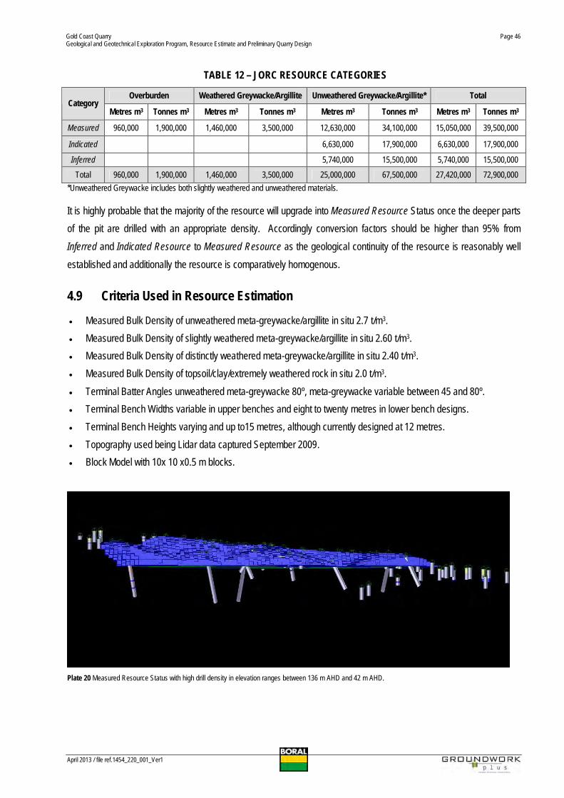
4.9 Criteria Used in Resource Estimation
· Measured Bulk Density of unweathered meta-greywacke/argillite in situ 2.7 t/m3.· Measured Bulk Density of slightly weathered meta-greywacke/argillite in situ 2.60 t/m3.· Measured Bulk Density of distinctly weathered meta-greywacke/argillite in situ 2.40 t/m3.· Measured Bulk Density of topsoil/clay/extremely weathered rock in situ 2.0 t/m3.· Terminal Batter Angles unweathered meta-greywacke 80º, meta-greywacke variable between 45 and 80º.· Terminal Bench Widths variable in upper benches and eight to twenty metres in lower bench designs.· Terminal Bench Heights varying and up to15 metres, although currently designed at 12 metres.· Topography used being Lidar data captured September 2009.· Block Model with 10x 10 x0.5 m blocks.
Plate 20 Measured Resource Status with high drill density in elevation ranges between 136 m AHD and 42 m AHD.

Gold Coast QuarryGeological and Geotechnical Exploration Program, Resource Estimate and Preliminary Quarry Design
April 2013 / file ref.1454_220_001_Ver1
Page 47
Plate 21 Indicated Resource Status with modest drill density in elevation ranges between 6 m AHD and 42 m AHD. Green denotes unweathered rock within themodel. Yellow and red denote weathered rock in the drainage line to the south east sector of the site.
Plate 22 Indicated Resource Status with modest drill density in elevation ranges between 6 m AHD and 42 m AHD. Importantly, geological continuity betweenresources in the measured indicated and inferred resource category and it is simply a lack of drill density that limits the higher classification of material in the base ofthe pit.

Gold Coast QuarryGeological and Geotechnical Exploration Program, Resource Estimate and Preliminary Quarry Design
April 2013 / file ref.1454_220_001_Ver1
Page 48
Plate 23 Inferred Resource Status with little drill density in elevation ranges between 6 m and -66 m AHD. The drill coverage which does exist in this area doesconfirm the continuity and homogeneity of the greywacke resource at depth.
Plate 24 Inferred Resource Status with little modest drill density in the elevation ranges between 6m AHD and -66 m AHD.
The resource estimate is based on in-situ volumes. The actual product yield will depend on a number of factorsincluding, (but not limited to), the final location and extent of the pit, the location of haul roads and terminal benchesunknown constraints which may affect the resource, blast yields and design, quarrying practice, unsaleable product andlosses due to quarrying, sales mix and plant configuration and other diluting factors. Likely yield tonnages i.e. productactually sold would typically be less than the insitu volume, once these modifying factors are considered.

Gold Coast QuarryGeological and Geotechnical Exploration Program, Resource Estimate and Preliminary Quarry Design
April 2013 / file ref.1454_220_001_Ver1
Page 49
Resultant of the completed drilling and mapping work is that the resource can be categorised under JORC 2004.Following is the classification system as set out in the JORC 2004 which is the Australasian Code for Reporting ofExploration Results, Mineral Resources and Ore Reserves.
TABLE 13 – JORC 2004 RESOURCE DIAGRAM
The resource estimate is based on in-situ volumes. The actual product yield will depend on a number of factorsincluding, (but not limited to), final pit design, geotechnical conditions, unsaleable product and losses due to mining,sales mix, plant configuration, haul road location and other diluting factors.
Geological mapping and drilling campaigns have assisted in defining the nature and extent of rock resources at the siteand from this work an adequate appreciation of rock resources was obtained.
The following estimates of exploitable rock resources at the site are based primarily on available geological data, allborehole data, and a considered final development plan for the quarry taking potential constraints which may affect theproject into consideration.
It should be noted that lithological, structural and weathering characteristics of rock deposits such as those which occurat this site are variable and may change over relatively short distances both laterally and with depth. Data interpretationhas required certain assumptions to be made and development planning has required adoption of certain operationalparameters which could be subject to change as quarrying progresses.

Gold Coast QuarryGeological and Geotechnical Exploration Program, Resource Estimate and Preliminary Quarry Design
April 2013 / file ref.1454_220_001_Ver1
Page 50
TABLE 14 – STAGE VOLUMES
Q1Material Volume m3 Tonnes m3
Overburden 500,000 1,000,000Weathered 660,000 1,580,000
Fresh 890,000 2,400,000Total 2,050,000 4,980,000
Q2Material Volume m3 Tonnes m3
Overburden 570,000 1,140,000Weathered 860,000 2,060,000
Fresh 2,570,000 6,940,000Total 4,000,000 10,140,000
Q3Material Volume m3 Tonnes m3
Overburden 750,000 1,500,000Weathered 1,130,000 2,712,000
Fresh 7,850,000 21,195,000Total 9,730,000 25,410,000
Q4Material Volume m3 Tonnes m3
Overburden 900,000 1,800,000Weathered 1,390,000 3,340,000
Fresh 14,840,000 40,070,000Total 17,130,000 45,210,000
Q5Material Volume m3 Tonnes m3
Overburden 960,000 1,900,000Weathered 1,460,000 3,500,000
Fresh 25,000,000 67,500,000Total 27,420,000 72,900,000

Gold Coast QuarryGeological and Geotechnical Exploration Program, Resource Estimate and Preliminary Quarry Design
April 2013 / file ref.1454_220_001_Ver1
Page 51
4.10 Assumptions and Parameters
The resource estimate provided assumes that:
· the limits of quarrying are in keeping with the area currently gazetted for extraction or under application;· the resource has acceptable lithological uniformity and general weathering characteristics as indicated by
exposure and drilling results;· the engineering properties of the various source rock types quarried are adequately reflected by the materials
testing results;· the lowest extraction elevations for the quarry at this point in time will be -66 m AHD; and· the development as proposed meets development approval and other statutory requirements and is carried out in
accordance with accepted quarry practice.
4.11 Resource Classification
Following is the classification system as set out in the JORC 2004 which is the Australasian Code for Reporting ofExploration Results, Mineral Resources and Ore Reserves.
A 'Measured Mineral Resource' is that part of a Mineral Resource for which tonnage, densities, shape, physicalcharacteristics, grade and mineral content can be estimated with a high level of confidence. It is based on detailed andreliable exploration, sampling and testing information gathered through appropriate techniques from locations such asoutcrops, trenches, pits, workings and drill holes. The locations are spaced closely enough to confirm geological and/orgrade continuity.
Measured Resources are estimated from geological mapping combined with borehole data and topographic data.
An 'Indicated Mineral Resource' is that part of a Mineral Resource for which tonnage, densities, shape, physicalcharacteristics, grade and mineral content can be estimated with a reasonable level of confidence. It is based onexploration, sampling and testing information gathered through appropriate techniques from locations such as outcrops,trenches, pits, workings and drill holes. The locations are too widely or inappropriately spaced to confirm geologicaland/or grade continuity, but are spaced closely enough for continuity to be assumed.
The resource confidence assigned to each unit is at the discretion of the Competent Person to determine what is themost robust category to define the resource and in considering all other salient factors that may influence the resource.
An 'Inferred Mineral Resource' is that part of a Mineral Resource for which tonnage, grade and mineral content can beestimated with a low level of confidence. It is inferred from geological evidence and assumed but not verified geologicaland/or grade continuity. It is based on information gathered through appropriate techniques from locations such asoutcrops, trenches, pits, workings and drill holes which may be limited or of uncertain quality and reliability.

Gold Coast QuarryGeological and Geotechnical Exploration Program, Resource Estimate and Preliminary Quarry Design
April 2013 / file ref.1454_220_001_Ver1
Page 52
An Inferred Resource is estimated from widely spaced surface drilling and surface geological mapping.
An 'Ore Reserve' is the economically mineable part of a Measured or Indicated Mineral Resource. It includes dilutingmaterials and allowances for losses which may occur when the material is mined. Appropriate assessments which mayinclude feasibility studies, have been carried out and include consideration of and modification by realistically assumedmining, metallurgical, economic, marketing, legal, environmental, social and governmental factors. These assessmentsdemonstrate at the time of reporting that extraction could reasonably be justified.
Ore Reserves are sub-divided in order of increasing confidence into Probable Ore Reserves and Proven Ore Reserves.A 'Proven Ore Reserve' is the economically mineable part of a Measured Mineral Resource. It includes dilutingmaterials and allowances for losses which may occur when the material is mined. Appropriate assessments, whichmay include feasibility studies, have been carried out, and include consideration of and modification by realisticallyassumed mining, metallurgical, economic, marketing, legal, environmental, social and governmental factors. Theseassessments demonstrate at the time of reporting that extraction could reasonably be justified.
A Probable Ore Reserve has a lower level of confidence than a Proven Ore Reserve. A 'Probable Ore Reserve' is theeconomically mineable part of an Indicated and in some circumstances Measured Mineral Resource. It includes dilutingmaterials and allowances for losses which may occur when the material is mined. Appropriate assessments which mayinclude feasibility studies, have been carried out and include consideration of and modification by realistically assumedmining, metallurgical, economic, marketing, legal, environmental, social and governmental factors. These assessmentsdemonstrate at the time of reporting that extraction could reasonably be justified.
Measured Resources are examined in 3D to determine the bench height, workable faces and infrastructure costs.Bench ore blocks are designed which include dilution, if this is deemed necessary. The resultant tabulation of reservesis termed Probable Ore Reserves. Due to the uncertainty which may attach to some Inferred Mineral Resources, itcannot be assumed that all or part of an Inferred Mineral Resource will be upgraded to an Indicated or MeasuredMineral Resource as a result of continued exploration and development. Confidence in the estimate is usually notsufficient to allow the appropriate application of technical and economic parameters or to enable an evaluation ofeconomic viability.
The measured resource estimate is based on in-situ volumes. The actual product yield will depend on a number offactors including (but not limited to) the variation in weathering and rock quality, site geology and variances in the blockmodel, useable product and losses due to mining, blasting method, extraction method, processing and plantconfiguration and location, basement elevation variations, haul road location and other diluting factors.

Gold Coast QuarryGeological and Geotechnical Exploration Program, Resource Estimate and Preliminary Quarry Design
April 2013 / file ref.1454_220_001_Ver1
Page 53
4.12 Database Validation
As part of the resource estimation procedure, the database project was audited. As part of the auditing process theoriginal data, where practical, was revisited for accuracy and updated for consistency.
5. Geotechnical InvestigationsPursuant to the below summarised scope of the works for the project the following geotechnical work was completed:
· report to Boral on geotechnical issues and design constraints;· 3D resource model in hard and digital format (compatible with Boral licensed software); and· highlight major risks given development speed and outline possible options for further staged geotechnical and
geological resource model data collection being mindful of speed timing of development; and Suggest ongoingmonitoring programs and data collection from site to improve both models over time.
5.1 Project Setting
To fully understand and appreciate the nature of the rock mass on site, significant time was spent in visiting the majorityof nearby road cuttings and also in conducting a review and geotechnical assessment of Boral’s West Burleigh Quarry.Data points and information used in assessment of the expected geotechnical conditions of the site are indicated onFIGURE 19 – GEOTECHNICAL DATA POINTS. While multiple sites were visited, and have been visited previously,the best indicators of likely performance in service life of the benches, slopes and void are submitted to be the OldCoach Road road cuttings, Helensvale M1 Road Cutting and Boral Ormeau and West Burleigh Quarries. Several of theother quarries excavated in the Neranleigh-Fernvale Beds have been worked on by the author however due tocommercial sensitivities only general information from these projects can be used.
Importantly and instructively, West Burleigh Quarry is considered as a “Bonsai” or a very close representation of theexpected geotechnical conditions which will be encountered on the project site. Accordingly the information gatheredfrom this site which is less than two kilometres away has exerted a large influence of the final design of the proposedquarry as the failure mechanisms overall batter bench and slope stability and rock mass characteristics on both sitesare similar. Additionally and as part of completing the geological and geotechnical design work, several of the roadcuttings in the immediate vicinity, were reviewed to determine the nature of the rock mass and performance in serviceof the excavation. Other salient features including rock type, general geotechnical domains, and failure mechanisms ifany, were recorded and analysed to determine their relevance for design criteria at the proposed Quarry.

Gold Coast QuarryGeological and Geotechnical Exploration Program, Resource Estimate and Preliminary Quarry Design
April 2013 / file ref.1454_220_001_Ver1
Page 54
Plate 24A Level Plan of the block model at 100m AHD. Green denotes unweathered rock, red slightly weathered, light blue distinctly weathered and yellow isoverburden i.e. residual soils and extremely weathered material.
5.2 West Burleigh Quarry Geotechnical Review
To ensure that previous lessons were learnt and integrated into the proposed design for the site, significant time wasspent in reviewing the geology and geotechnical conditions of both Boral’s West Burleigh and Ormeau Quarries.Review of West Burleigh Quarry clearly demonstrates that bench integrity and stability is good, and while minor andimmaterial house keeping items could be addressed, the overall geotechnical conditions of the quarry are benign, andthe design criteria used are suitable. Furthermore the benches in the high wall are stable and their performance inservice, while hackly, is good.