sun storedge™ 3310 scsi array installation, operation, … · sun microsystems, inc. 4150 network...
TRANSCRIPT
Sun Microsystems, Inc.4150 Network CircleSanta Clara, CA 95054 U.S.A.650-960-1300
Send comments about this document to: [email protected]
Sun StorEdge™ 3310 SCSI ArrayInstallation, Operation, and Service
Manual™
Part No. 816-7290-11October 2002, Revision 01

PleaseRecycle
Copyright © 2002 Dot Hill Systems Corporation, 6305 El Camino Real, Carlsbad, California 92009, USA. All rights reserved.
Sun Microsystems, Inc. and Dot Hill Corporation may have intellectual property rights relating to technology embodied in this product ordocument. In particular, and without limitation, these intellectual property rights may include one or more of the U.S. patents listed athttp://www.sun.com/patents and one or more additional patents or pending patent applications in the U.S. and other countries.
This product or document is distributed under licenses restricting its use, copying distribution, and decompilation. No part of this product ordocument may be reproduced in any form by any means without prior written authorization of Sun and its licensors, if any.
Third-party software is copyrighted and licensed from Sun suppliers.
Parts of the product may be derived from Berkeley BSD systems, licensed from the University of California. UNIX is a registered trademark inthe U.S. and in other countries, exclusively licensed through X/Open Company, Ltd.
Sun, Sun Microsystems, the Sun logo, AnswerBook2, docs.sun.com, and Solaris are trademarks or registered trademarks of Sun Microsystems,Inc. in the U.S. and in other countries.
Federal Acquisitions: Commercial Software - Government Users Subject to Standard License Terms and Conditions.
DOCUMENTATION IS PROVIDED “AS IS” AND ALL EXPRESS OR IMPLIED CONDITIONS, REPRESENTATIONS AND WARRANTIES,INCLUDING ANY IMPLIED WARRANTY OF MERCHANTABILITY, FITNESS FOR A PARTICULAR PURPOSE OR NONINFRINGEMENT,ARE DISCLAIMED, EXCEPT TO THE EXTENT THAT SUCH DISCLAIMERS ARE HELD TO BE LEGALLY INVALID.
Copyright © 2002 Dot Hill Systems Corporation, 6305 El Camino Real, Carlsbad, Californie 92009, USA. Tous droits réservés.
Sun Microsystems, Inc. et Dot Hill Systems Corporation peuvent avoir les droits de propriété intellectuels relatants à la technologie incorporéedans ce produit. En particulier, et sans la limitation, ces droits de propriété intellectuels peuvent inclure un ou plus des brevets américainsénumérés à http://www.sun.com/patents et un ou les brevets plus supplémentaires ou les applications de brevet en attente dans les Etats -Unis et les autres pays.
Ce produit ou document est protégé par un copyright et distribué avec des licences qui en restreignent l'utilisation, la copie, la distribution, et ladécompilation. Aucune partie de ce produit ou document ne peut être reproduite sous aucune forme, par quelque moyen que ce soit, sansl'autorisation préalable et écrite de Sun et de ses bailleurs de licence, s'il y ena.
Le logiciel détenu par des tiers, et qui comprend la technologie relative aux polices de caractères, est protégé par un copyright et licencié par desfournisseurs de Sun.
Des parties de ce produit pourront être dérivées des systèmes Berkeley BSD licenciés par l'Université de Californie. UNIX est une marquedéposée aux Etats-Unis et dans d'autres pays et licenciée exclusivement par X/Open Company, Ltd.
Sun, Sun Microsystems, le logo Sun, AnswerBook2, docs.sun.com, et Solaris sont des marques de fabrique ou des marques déposées de SunMicrosystems, Inc. aux Etats-Unis et dans d’autres pays.
LA DOCUMENTATION EST FOURNIE “EN L'ETAT” ET TOUTES AUTRES CONDITIONS, CONDITIONS, DECLARATIONS ETGARANTIES EXPRESSES OU TACITES SONT FORMELLEMENT EXCLUES, DANS LA MESURE AUTORISEE PAR LA LOI APPLICABLE, YCOMPRIS NOTAMMENT TOUTE GARANTIE IMPLICITE RELATIVE A LA QUALITE MARCHANDE, A L'APTITUDE A UNEUTILISATION PARTICULIERE OU A L'ABSENCE DE CONTREFAÇON.
Contents
Preface ix
1. Array Overview 1–1
1.1 Introducing the Array Models 1–1
1.2 Task Map 1–3
1.3 Additional Software Tools 1–4
2. Site Planning 2–1
2.1 Customer Obligations 2–2
2.2 Safety Precautions 2–2
2.3 Environmental Requirements 2–3
2.3.1 Electromagnetic Compatibility (EMC) 2–3
2.4 Electrical and Power Specifications 2–4
2.5 Physical Specifications 2–5
2.6 Layout Map 2–5
2.6.1 Rack Placement 2–5
2.6.2 Tabletop Placement 2–6
2.7 Console and Other Requirements 2–7
2.8 Preinstallation Worksheet 2–7
iii
3. Inspecting the Array Package 3–1
3.1 Unpacking the Array 3–2
3.2 Checking the Package Contents 3–3
3.2.1 Standard Sun StorEdge 3310 SCSI Array Package 3–3
3.2.2 Options/Field Replaceable Units 3–4
3.3 Customer-Provided Cables 3–4
4. Rackmounting 4–1
4.1 Required Site and Chassis Preparation 4–2
4.2 Cabinet Mounting 4–3
4.3 Telco Rackmounting 4–9
4.3.1 Flushmount Configuration 4–10
4.3.2 Center-of-Gravity Configuration 4–13
4.4 Powering Up and Checking LEDs 4–16
5. Connecting Ports 5–1
5.1 Connecting Chassis to an AC Power Outlet 5–3
5.2 Connecting the Chassis to DC Power Outlets 5–4
5.3 Reviewing Single Versus Dual Drive-Bus Configurations 5–5
5.4 Connecting Cables for a Single Bus Configuration 5–8
5.5 Connecting Cables for a Dual Bus Configuration 5–11
5.6 Connecting SCSI Ports to Host(s) 5–14
5.6.1 Sun StorEdge 3310 RAID Array 5–14
5.6.2 Sun StorEdge 3310 JBOD Array 5–15
5.7 Cabling Configurations with Two Expansion Units 5–16
5.8 Connecting COM Port to a VT100 Terminal or Solaris Workstation 5–18
5.9 Connecting Ethernet Ports to LAN/WAN (Optional) 5–18
iv Sun StorEdge™ 3310 SCSI Array Installation, Operation, and Service Manual • October 2002
6. First-Time Configuration 6–1
6.1 Controller Defaults and Limitations 6–2
6.2 Battery Operation 6–3
6.3 Accessing the Management Tools 6–3
6.4 First-Time Controller Configuration 6–4
6.4.1 Setting Up the Serial Port Connection 6–5
6.4.2 Viewing the Initial Firmware Windows 6–7
6.4.3 Configuring SCSI Channels as Host or Drive (Optional) 6–8
6.4.4 Creating Additional Host IDs (Optional) 6–10
6.4.5 Enabling a Solaris Host to Recognize New Devices and LUNs 6–12
6.4.6 Reviewing Default Logical Drives and RAID Levels 6–13
6.4.7 Completing Basic Configuration 6–14
6.4.8 Creating Logical Drive(s) (optional) 6–14
6.4.9 Changing a Logical Drive Controller Assignment (Optional) 6–21
6.4.10 Partitioning a Logical Drive (optional) 6–22
6.4.11 Planning for 128 LUNs (Optional) 6–26
6.4.12 Mapping Logical Drive Partitions to Host LUNs 6–27
6.4.13 Create Device Files for Solaris Environment 6–30
6.4.14 Saving Configuration (NVRAM) to a Disk 6–31
6.5 Installing Software 6–32
6.5.1 Other Supported Software 6–32
6.5.2 Enabling VERITAS DMP 6–32
Contents v
7. Checking LEDs 7–1
7.1 LEDs When Array Is First Powered On 7–1
7.2 Front-Panel LEDs 7–3
7.3 Rear-Panel LEDs 7–5
7.3.1 RAID Controller LEDs 7–5
7.3.2 Other Rear-Panel LEDs 7–7
8. Maintaining and Troubleshooting Your Array 8–1
8.1 Problem In Seeing the Array on the Host 8–2
8.1.1 RAID LUNs Not Visible to the Host 8–2
8.1.2 JBOD Disks Not Visible to the Host 8–3
8.2 Key Screens and Commands 8–3
8.2.1 The Controller Firmware Initial Screen 8–3
8.2.2 Main Menu 8–4
8.2.3 Quick Installation 8–5
8.3 Checking Status Windows 8–5
8.3.1 Logical Drive Status Table 8–5
8.3.2 Logical Volume Status Table 8–7
8.3.3 SCSI Drive Status Table 8–8
8.3.4 SCSI Channel Status Table 8–10
8.3.5 Controller Voltage Temperature Status 8–12
8.3.6 Viewing SAF-TE Status 8–13
8.3.7 Viewing Event Logs on the Screen 8–15
8.4 Controller Failure Symptoms, Logical Drive Rebuild, and Replacement 8–16
8.4.1 General Controller Failure Response 8–16
8.4.2 Automatic Logical Drive Rebuild 8–17
8.4.3 Manual Rebuild 8–17
8.4.4 Concurrent Rebuild in RAID (0+1) 8–20
vi Sun StorEdge™ 3310 SCSI Array Installation, Operation, and Service Manual • October 2002
8.4.5 Identifying a Failed Drive for Replacement 8–20
8.4.6 Restoring Your Configuration (NVRAM) From a File 8–23
8.4.7 Fatal Drive Failure 8–24
8.5 Upgrading Firmware 8–25
8.5.1 Review Firmware Upgrade Features 8–25
8.5.2 Downloading Firmware Upgrades 8–26
9. Installing Spares and FRUs 9–1
9.1 Static Electricity Precautions 9–2
9.2 Replacing a Drive 9–3
9.3 Replacing a Controller Module 9–4
9.4 Replacing I/O Modules 9–6
9.5 Replacing a Power/Fan Module 9–7
9.6 Replacing the Terminator Module 9–8
9.7 Replacing the EMU Module 9–10
9.8 Replacing the Battery 9–11
A. SCSI Array Specifications A–1
A.1 Summary of Sun StorEdge 3310 SCSI Array Specifications A–2
A.2 Agency Approvals and Standards A–3
B. Cabling JBODs B–1
B.1 A Single Bus JBOD with One Host Connection B–2
B.2 A Single Bus JBOD with Two Host Connections B–3
B.3 Dual Bus JBOD Configurations B–4
B.3.1 Dual Bus, Single Initiator Mode B–5
B.3.2 Dual Bus, Multi-Initiator Mode B–6
Contents vii
C. Ethernet Connection C–1
C.1 Setting an IP Address C–1
C.2 Setting Up Out-of-Band Management Over Ethernet C–3
D. Record of Settings D–1
D.1 View and Edit Logical Drives D–2
D.1.1 Logical Drive Information D–2
D.1.2 Logical Drive Partition Information D–3
D.2 View and Edit Host LUNs D–4
D.2.1 LUN Mappings D–4
D.3 View and Edit SCSI Drives D–5
D.4 View and Edit SCSI Channels D–6
D.5 View and Edit Peripheral Devices D–8
D.6 Save NVRAM to Disk, Restore from Disk D–8
E. Solaris sd.conf Setup and Volume Labels E–1
E.1 Editing the sd.conf File E–1
E.2 Labeling a Volume E–3
F. Cable Pinouts F–1
F.1 SCSI (Host or Drive) Connector F–1
F.2 RJ-45 Connector F–3
F.3 DB9 COM port F–4
viii Sun StorEdge™ 3310 SCSI Array Installation, Operation, and Service Manual • October 2002
Preface
The Sun™ StorEdge™ 3310 SCSI Array Installation, Operation, and Service Manualgives step-by-step procedures for installing and initially configuring the SunStorEdge 3310 SCSI array. Field-replacement unit (FRU) procedures are alsoincluded.
Caution – You should read the Sun StorEdge 3310 SCSI Array Safety, Regulatory, andCompliance Manual before beginning any procedure in this manual.
How This Book Is OrganizedThis book contains the following topics:
Chapter 1 provides an overview of RAID features.
Chapter 2 covers the site planning and basic safety requirements.
Chapter 3 provides general procedures for unpacking and inspecting the array.
Chapter 4 provides procedures for rackmounting the array.
Chapter 5 provides procedures for cabling and for connecting to power and to thenetwork.
Chapter 6 provides procedures for a first-time configuration.
Chapter 7 describes the front and rear panel LEDs.
Chapter 8 provides maintenance and troubleshooting procedures.
Chapter 9 provides procedures for installing spares and FRUs.
ix
Appendix A provides Sun StorEdge 3310 array specifications.
Appendix B shows how to cable JBODs to one or more host servers.
Appendix C provides Ethernet connection instructions.
Appendix D provides tables for recording configuration data.
Appendix E provides information about editing the sd.conf file when adding hostLUN assignments.
Appendix F provides pinout identification for each connector.
Using UNIX CommandsThis document might not contain information on basic UNIX® commands andprocedures such as shutting down the system, booting the system, and configuringdevices.
See one or more of the following for this information:
■ Solaris Handbook for Sun Peripherals■ AnswerBook2™ online documentation for the Solaris™ operating system■ Other software documentation that you received with your system
x Sun StorEdge™ 3310 SCSI Array Installation, Operation, and Service Manual • October 2002
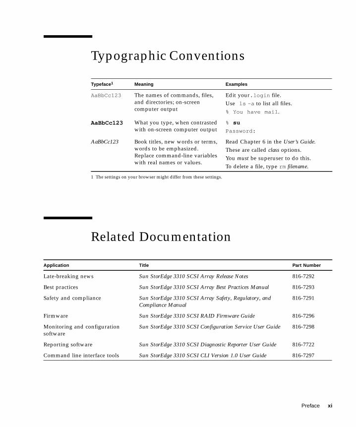
Typographic Conventions
Related Documentation
Typeface1
1 The settings on your browser might differ from these settings.
Meaning Examples
AaBbCc123 The names of commands, files,and directories; on-screencomputer output
Edit your.login file.Use ls -a to list all files.% You have mail.
AaBbCc123 What you type, when contrastedwith on-screen computer output
% su
Password:
AaBbCc123 Book titles, new words or terms,words to be emphasized.Replace command-line variableswith real names or values.
Read Chapter 6 in the User’s Guide.These are called class options.You must be superuser to do this.To delete a file, type rm filename.
Application Title Part Number
Late-breaking news Sun StorEdge 3310 SCSI Array Release Notes 816-7292
Best practices Sun StorEdge 3310 SCSI Array Best Practices Manual 816-7293
Safety and compliance Sun StorEdge 3310 SCSI Array Safety, Regulatory, andCompliance Manual
816-7291
Firmware Sun StorEdge 3310 SCSI RAID Firmware Guide 816-7296
Monitoring and configurationsoftware
Sun StorEdge 3310 SCSI Configuration Service User Guide 816-7298
Reporting software Sun StorEdge 3310 SCSI Diagnostic Reporter User Guide 816-7722
Command line interface tools Sun StorEdge 3310 SCSI CLI Version 1.0 User Guide 816-7297
Preface xi
Technical SupportFor late-breaking news and troubleshooting tips, review the Sun StorEdge 3310 SCSIArray Release Notes located at:
www.sun.com/products-n-solutions/hardware/docs/Network_Storage_Solutions/Workgroup/3310
For 24-hour access to web-based support solutions, visit the Online Support Centerat:
www.sun.com/service/online
To initiate or check on a USA-only service request, contact Sun support at:
1-800-USA4SUN
To obtain international technical support, contact the sales office of a specific countryat:
www.sun.com/service/contacting/sales.html
Accessing Sun Documentation OnlineAll Sun StorEdge 3310 SCSI Array online documentation is located at:
http://www.sun.com/products-n-solutions/hardware/docs/Network_Storage_Solutions/Workgroup/3310
You can order printed copies of the Sun StorEdge 3310 SCSI array manuals at:
http://corppub.iuniverse.com/marketplace/sun
You can view, print, or purchase a broad selection of Sun documentation, includinglocalized versions, at:
http://www.sun.com/documentation
xii Sun StorEdge™ 3310 SCSI Array Installation, Operation, and Service Manual • October 2002

Sun Welcomes Your CommentsSun is interested in improving its documentation and welcomes your comments andsuggestions. You can email your comments to Sun at:
Please include the part number (816-7290-11) of your document in the subject line ofyour email.
Preface xiii

xiv Sun StorEdge™ 3310 SCSI Array Installation, Operation, and Service Manual • October 2002
CHAPTER 1
Array Overview
This chapter provides a brief overview of your Sun StorEdge 3310 SCSI array whichis an LVD/SE device. Topics covered in this chapter are:
■ “Introducing the Array Models” on page 1-1■ “Task Map” on page 1-3■ “Additional Software Tools” on page 1-4
1.1 Introducing the Array ModelsThe Sun StorEdge 3310 SCSI array models include:
■ A redundant array of independent disks (RAID) with a single controller■ A RAID with two controllers■ An expansion unit or JBOD (an array with disks and no controller)
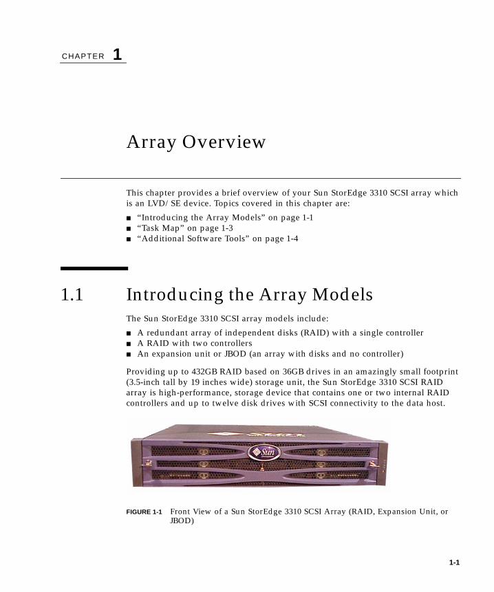
Providing up to 432GB RAID based on 36GB drives in an amazingly small footprint(3.5-inch tall by 19 inches wide) storage unit, the Sun StorEdge 3310 SCSI RAIDarray is high-performance, storage device that contains one or two internal RAIDcontrollers and up to twelve disk drives with SCSI connectivity to the data host.
FIGURE 1-1 Front View of a Sun StorEdge 3310 SCSI Array (RAID, Expansion Unit, orJBOD)
1-1
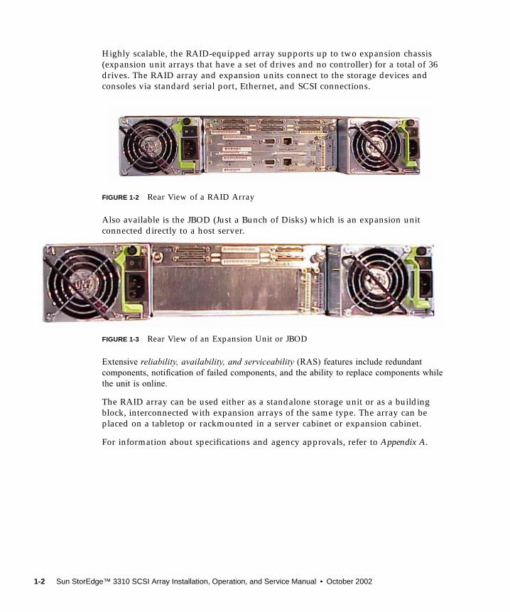
Highly scalable, the RAID-equipped array supports up to two expansion chassis(expansion unit arrays that have a set of drives and no controller) for a total of 36drives. The RAID array and expansion units connect to the storage devices andconsoles via standard serial port, Ethernet, and SCSI connections.
FIGURE 1-2 Rear View of a RAID Array
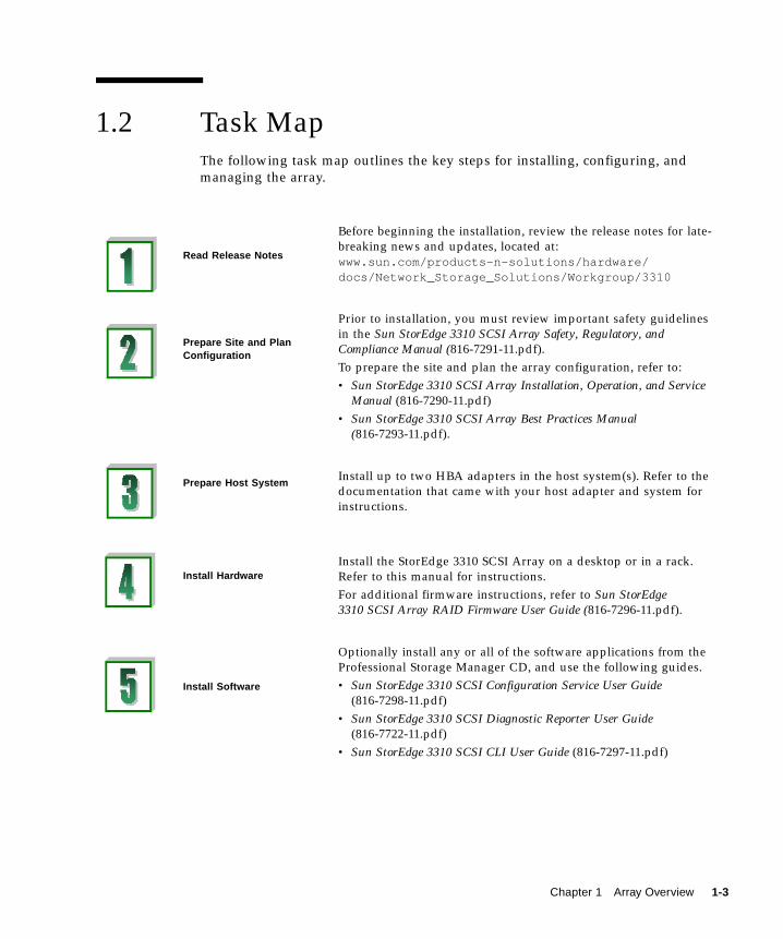
Also available is the JBOD (Just a Bunch of Disks) which is an expansion unitconnected directly to a host server.
FIGURE 1-3 Rear View of an Expansion Unit or JBOD
Extensive reliability, availability, and serviceability (RAS) features include redundantcomponents, notification of failed components, and the ability to replace components whilethe unit is online.
The RAID array can be used either as a standalone storage unit or as a buildingblock, interconnected with expansion arrays of the same type. The array can beplaced on a tabletop or rackmounted in a server cabinet or expansion cabinet.
For information about specifications and agency approvals, refer to Appendix A.
1-2 Sun StorEdge™ 3310 SCSI Array Installation, Operation, and Service Manual • October 2002
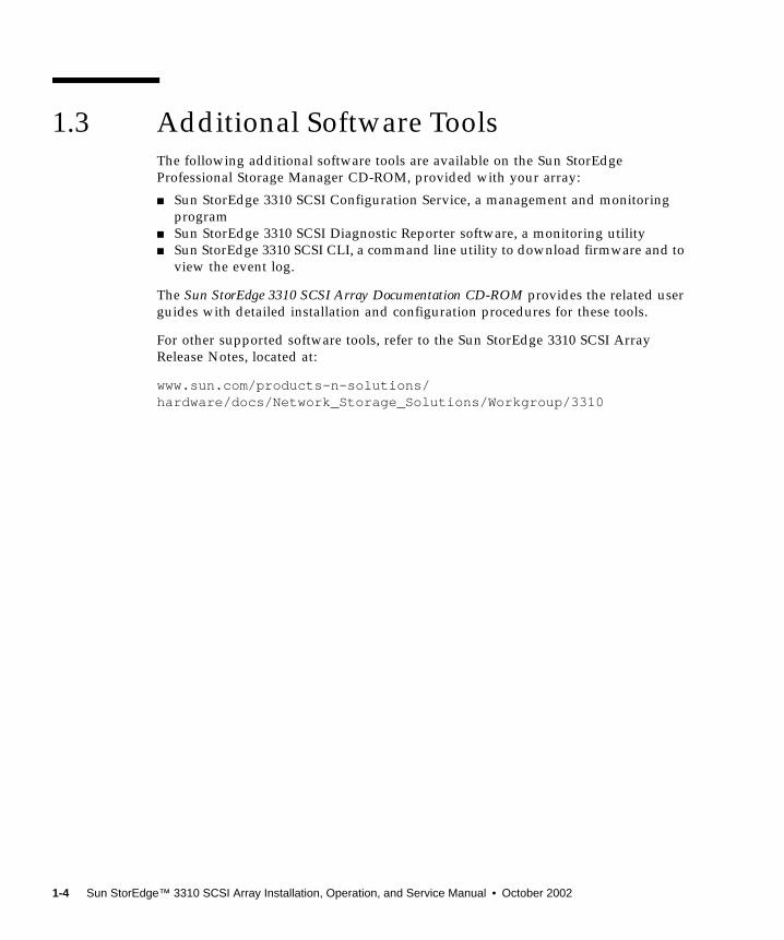
1.2 Task MapThe following task map outlines the key steps for installing, configuring, andmanaging the array.
Read Release Notes
Before beginning the installation, review the release notes for late-breaking news and updates, located at:www.sun.com/products-n-solutions/hardware/docs/Network_Storage_Solutions/Workgroup/3310
Prepare Site and PlanConfiguration
Prior to installation, you must review important safety guidelinesin the Sun StorEdge 3310 SCSI Array Safety, Regulatory, andCompliance Manual (816-7291-11.pdf).To prepare the site and plan the array configuration, refer to:• Sun StorEdge 3310 SCSI Array Installation, Operation, and Service
Manual (816-7290-11.pdf)• Sun StorEdge 3310 SCSI Array Best Practices Manual
(816-7293-11.pdf).
Prepare Host SystemInstall up to two HBA adapters in the host system(s). Refer to thedocumentation that came with your host adapter and system forinstructions.
Install HardwareInstall the StorEdge 3310 SCSI Array on a desktop or in a rack.Refer to this manual for instructions.For additional firmware instructions, refer to Sun StorEdge3310 SCSI Array RAID Firmware User Guide (816-7296-11.pdf).
Install Software
Optionally install any or all of the software applications from theProfessional Storage Manager CD, and use the following guides.• Sun StorEdge 3310 SCSI Configuration Service User Guide
(816-7298-11.pdf)• Sun StorEdge 3310 SCSI Diagnostic Reporter User Guide
(816-7722-11.pdf)• Sun StorEdge 3310 SCSI CLI User Guide (816-7297-11.pdf)
Chapter 1 Array Overview 1-3
1.3 Additional Software ToolsThe following additional software tools are available on the Sun StorEdgeProfessional Storage Manager CD-ROM, provided with your array:
■ Sun StorEdge 3310 SCSI Configuration Service, a management and monitoringprogram
■ Sun StorEdge 3310 SCSI Diagnostic Reporter software, a monitoring utility■ Sun StorEdge 3310 SCSI CLI, a command line utility to download firmware and to
view the event log.
The Sun StorEdge 3310 SCSI Array Documentation CD-ROM provides the related userguides with detailed installation and configuration procedures for these tools.
For other supported software tools, refer to the Sun StorEdge 3310 SCSI ArrayRelease Notes, located at:
www.sun.com/products-n-solutions/hardware/docs/Network_Storage_Solutions/Workgroup/3310
1-4 Sun StorEdge™ 3310 SCSI Array Installation, Operation, and Service Manual • October 2002
CHAPTER 2
Site Planning
This chapter outlines the site-planning requirements and basic safety requirementsfor the installation and use of Sun StorEdge 3310 SCSI arrays. Customers are askedto complete a “Preinstallation Worksheet” on page 2-7 and to prepare the site forinstallation according to the worksheet details and the specified site planningrequirements.
Review the details of this chapter before installing a Sun StorEdge 3310 SCSI array.Topics covered in this chapter are:
■ “Customer Obligations” on page 2-2■ “Safety Precautions” on page 2-2■ “Environmental Requirements” on page 2-3■ “Electrical and Power Specifications” on page 2-4■ “Physical Specifications” on page 2-5■ “Layout Map” on page 2-5■ “Console and Other Requirements” on page 2-7■ “Preinstallation Worksheet” on page 2-7
Note – See Sun StorEdge 3310 SCSI Array Release Notes for the current lists ofsupported operating environments, host platforms, software, and qualified cabinets.
2-1
2.1 Customer ObligationsThe customer is obliged to inform Sun Microsystems, Inc. of any and all ordinancesand regulations that would affect installation.
Caution – When selecting an installation site for the Sun StorEdge 3310 SCSI array,choose a location that avoids excessive heat, direct sunlight, dust, or chemicalexposure. Such exposure greatly reduces the product’s longevity and might voidyour warranty.
The customer is responsible for meeting all government codes and regulationsconcerning facilities. The customer is also responsible for compliance with the followingrequirements:
■ Meet all local, national, and international codes covered in this specification. Thesubjects covered include fire and safety, building, and electrical codes.
■ Document and inform Sun Microsystems, Inc. of any deviations from thisspecification.
2.2 Safety PrecautionsFor your protection, observe the following safety precautions when setting up yourequipment:
■ Follow all safety precautions and requirements specified in the Sun StorEdge 3310SCSI Array Safety, Regulatory, and Compliance Manual.
■ A fully loaded array weighs over 50 pounds. Use two people to lift the array toavoid injury.
■ Follow all cautions and instructions marked on the equipment.
■ Ensure that the voltage and frequency of your power source match the voltage andfrequency inscribed on the equipment’s electrical rating label.
■ Never push objects of any kind through openings in the equipment. Dangerousvoltages may be present. Conductive foreign objects could produce a short circuitthat could cause fire, electric shock, or damage to your equipment.
2-2 Sun StorEdge™ 3310 SCSI Array Installation, Operation, and Service Manual • October 2002

■ To reduce the risk of electric shock, do not plug Sun products into any other typeof power system. Sun products are designed to work with single-phase powersystems having a grounded neutral conductor. Contact your facilities manager ora qualified electrician if you are not sure what type of power is supplied to yourbuilding.
■ Your Sun product is shipped with a grounding-type (three-wire) power cord. Toreduce the risk of electric shock, always plug the cord into a grounded poweroutlet.
■ Do not use household extension cords with your Sun product. Not all powercords have the same current ratings. Household extension cords do not haveoverload protection and are not meant for use with computer systems.
■ Do not block or cover the openings of your Sun product. Never place a Sunproduct near a radiator or heat register. Failure to follow these guidelines cancause overheating and affect the reliability of your Sun product.
2.3 Environmental Requirements
2.3.1 Electromagnetic Compatibility (EMC)The following is required for all installations:
■ All AC mains and supply conductors to power distribution boxes for both therackmounted array and the desktop array must be enclosed in a metal conduit orraceway when specified by local, national, and/or other applicable governmentcodes and regulations.
■ The supply conductors and power distribution boxes (or equivalent metalenclosure) must be grounded at both ends.
■ The supplied arrays require voltages within minimum fluctuation.
TABLE 2-1 Environmental Specifications
Operating Non-Operating
Altitude To 3000 meters (9000 feet). To 12,000 meters (36,000 feet)
Temperature 5 degrees C to 35 degrees C -40 degrees C to +65 degrees C
Humidity Range10% to 90% @ 40 degrees C(noncondensing)
0 to 93% @ 38degrees C (noncondensing)
Chapter 2 Site Planning 2-3
■ The facilities voltage supplied by the customer must maintain a voltage of notmore than (+/–) 5 percent. The customer facilities must provide suitable surgeprotection.
2.4 Electrical and Power SpecificationsAll Sun StorEdge 3310 SCSI arrays require two independent power sources. Eacharray has two power-supply-and-fan modules for redundancy.
Each Sun StorEdge 3310 AC array requires two 115 VAC/15A or two 240 VACservice outlets. All AC power supplies are autoranging and are automaticallyconfigured to a range of 90-264 VAC and 47-63 Hz. There is no need to make specialadjustments.
Each DC array requires two –48 VDC service outlets, and has a input voltage rangeof –36 VDC to –72 VDC.
Note – To ensure power redundancy, be sure to connect the two Sun StorEdge 3310SCSI power modules to two separate circuits (for example, one commercial circuitand one UPS).
TABLE 2-2 Power Specifications
AC power: Voltage and frequency 90 to 264 VAC, 47 to 63 Hz
Input current: 5A max
Power-supply output voltages: +5 VDC and +12 VDC
DC power: –48V DC (–36 VDC to –72 VDC)
2-4 Sun StorEdge™ 3310 SCSI Array Installation, Operation, and Service Manual • October 2002
2.5 Physical SpecificationsUse the following physical specifications to plan the location of your array.
2.6 Layout MapIt is helpful to create a sketch or layout map to indicate the exact location for the SunStorEdge 3310 SCSI array installation as well as the location of the hosts, console,and Ethernet connections that will be connected to it.
As you lay out the components, consider the cable lengths that will be used.
2.6.1 Rack PlacementFollow these guidelines when preparing a rackmount placement for your system.
■ Ensure that the floor surface is level.
■ Leave enough space in front of the rack to access components for servicing.
■ Leave enough space in back of the rack to access components for servicing.
■ Keep power and interface cables clear of foot traffic. Route cables inside walls,under the floor, through the ceiling, or in protective channels or raceways.
TABLE 2-3 Physical Specifications
Category Description
Dimensions 2U (3.5-in.) height20-in.chassis depth17.5-in.(19 in.with ears) width
Installation clearances For FRU removal and replacement, 15-in.(37 cm) is required frontand back.
Cooling clearances 6-in. (15 cm) is required front and back. No cooling clearance isrequired on the sides or the top and bottom of the array.
Chapter 2 Site Planning 2-5
■ Route interface cables (excluding fiber-optic cables) away from motors and othersources of magnetic or radio frequency interference.
■ Stay within the cable length limitations.
■ Provide two separate power sources for the array. These power sources must beindependent of each other, and each must be controlled by a separate circuitbreaker at the power distribution point.
2.6.2 Tabletop PlacementSun StorEdge 3310 SCSI arrays can be positioned on a desk or a table. Follow theseguidelines when preparing a tabletop placement for your system.
■ Choose a desk or a table that can support 50 pounds for one fully-configuredarray or 100 pounds for two arrays.
■ Do not place the array(s) on the edge of the table. Set the array so that at least 50percent of the array is inside the table or desk leg support area. Failure to do thismay cause the table to tip over.
■ Leave enough space in front and in back of the array to access components forservicing. To remove the components requires a clearance of 15 inches (37 cm) infront and in back of the array.
■ Provide a minimum space of 6 inches (15 cm) in front and in back of the array foradequate airflow.
■ Keep power and interface cables clear of foot traffic. Route cables inside walls,under the floor, through the ceiling, or in protective channels or raceways.
■ Route interface cables away from motors and other sources of magnetic or radiofrequency interference.
■ Stay within the cable length limitations.
■ Ensure that the operating system for the array does not exceed the specifications.
■ Use two people to lift the array to avoid injury. The array can weigh up to 50pounds.
■ Do not place the array in a vertical position. Place the array horizontally.
■ If you are installing two arrays, you can stack one array on top of the other. Donot stack more than two arrays together.
■ Provide two separate power sources for the array. These power sources must beindependent of each other, and each must be controlled by a separate circuitbreaker at the power distribution point.
2-6 Sun StorEdge™ 3310 SCSI Array Installation, Operation, and Service Manual • October 2002
2.7 Console and Other RequirementsA console (with one serial port or one Ethernet connection) is necessary forinstallation and configuration of your Sun StorEdge 3310 SCSI array.
Refer to the following Preinstallation Worksheet for additional preparation details.
2.8 Preinstallation WorksheetWhen ordering a Sun StorEdge 3310 SCSI array, complete the followingPreinstallation Worksheet and then prepare the site for installation according to thesite-planning requirements.
You are responsible for ensuring that the site consistently conforms to all stipulatedstandards, and that necessary peripherals are made available to the engineer duringinstallation.
Review the details of your specific survey before installing your Sun StorEdge 3310SCSI array.
Chapter 2 Site Planning 2-7
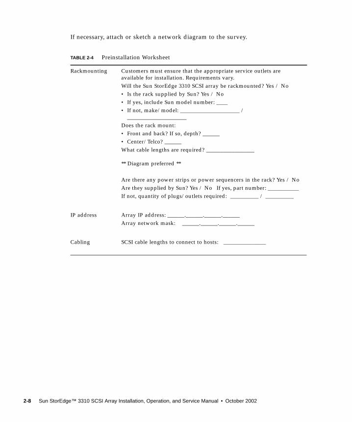
If necessary, attach or sketch a network diagram to the survey.
TABLE 2-4 Preinstallation Worksheet
Rackmounting Customers must ensure that the appropriate service outlets areavailable for installation. Requirements vary.Will the Sun StorEdge 3310 SCSI array be rackmounted? Yes / No• Is the rack supplied by Sun? Yes / No• If yes, include Sun model number: ____• If not, make/model: _____________________ /
_____________________Does the rack mount:• Front and back? If so, depth? ______• Center/Telco? ______What cable lengths are required? _________________
** Diagram preferred **
Are there any power strips or power sequencers in the rack? Yes / NoAre they supplied by Sun? Yes / No If yes, part number: ___________If not, quantity of plugs/outlets required: __________ / __________
IP address Array IP address: ______.______.______.______Array network mask: ______.______.______.______
Cabling SCSI cable lengths to connect to hosts: _______________
2-8 Sun StorEdge™ 3310 SCSI Array Installation, Operation, and Service Manual • October 2002
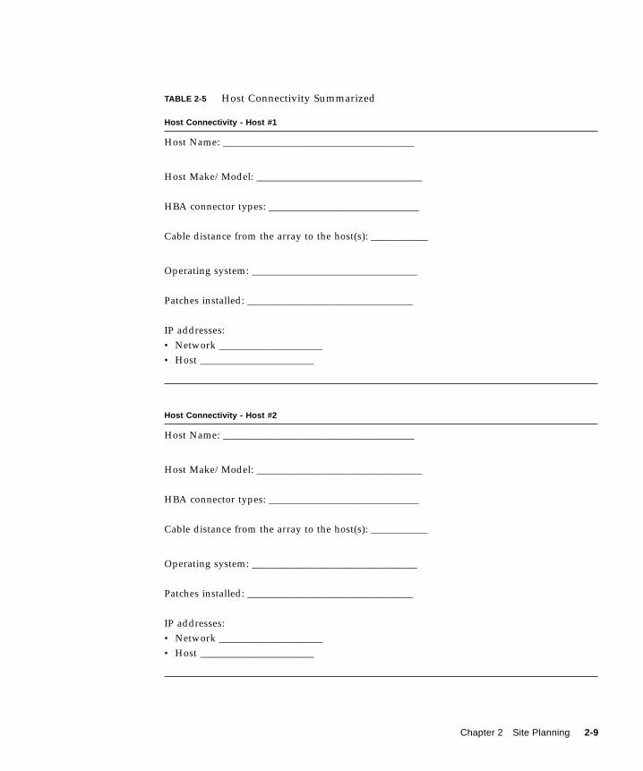
TABLE 2-5 Host Connectivity Summarized
Host Connectivity - Host #1
Host Name: _____________________________________
Host Make/Model: ________________________________
HBA connector types: _____________________________
Cable distance from the array to the host(s): ___________
Operating system: ________________________________
Patches installed: ________________________________
IP addresses:• Network ____________________• Host ______________________
Host Connectivity - Host #2
Host Name: _____________________________________
Host Make/Model: ________________________________
HBA connector types: _____________________________
Cable distance from the array to the host(s): ___________
Operating system: ________________________________
Patches installed: ________________________________
IP addresses:• Network ____________________• Host ______________________
Chapter 2 Site Planning 2-9

2-10 Sun StorEdge™ 3310 SCSI Array Installation, Operation, and Service Manual • October 2002
CHAPTER 3
Inspecting the Array Package
This chapter gives the general procedure for inspection and reviews the SunStorEdge 3310 SCSI array package. Topics covered in this chapter are as follows:
■ “Unpacking the Array” on page 3-2■ “Checking the Package Contents” on page 3-3
■ “Standard Sun StorEdge 3310 SCSI Array Package” on page 3-3.■ “Options/Field Replaceable Units” on page 3-4
■ “Customer-Provided Cables” on page 3-4
3-1
3.1 Unpacking the ArrayFollow these guidelines for unpacking the equipment.
Caution – Always use two people to remove the unit from its container, to avoidpersonal injury or damage to the equipment during installation. This unit weighsapproximately 50 pounds.
1. Select a suitable area for unpacking.
2. Store all packing material and boxes for possible equipment returns.
3. Check the Contents Sheet in your product package. See “Checking the PackageContents” on page 3-3.
The Contents Sheet summarizes the standard contents for your product.
4. Compare the packing slip and the list of parts with the items you received.
If the list of parts on your packing slip does not match the items you received, or anyitems appear damaged, immediately notify your carrier agent and the supplier whoprepared your shipment.
5. Carefully examine the cables provided in the package.
If any cable appears to be damaged, contact the Technical Service department for animmediate replacement.
6. Check the list of “Customer-Provided Cables” on page 3-4.
These are required to complete your installation.
Caution – You must purchase or provide 160M-compliant SCSI cables forconnecting the Sun StorEdge 3310 SCSI array to host servers.
3-2 Sun StorEdge™ 3310 SCSI Array Installation, Operation, and Service Manual • October 2002
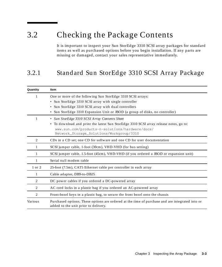
3.2 Checking the Package ContentsIt is important to inspect your Sun StorEdge 3310 SCSI array packages for standarditems as well as purchased options before you begin installation. If any parts aremissing or damaged, contact your sales representative immediately.
3.2.1 Standard Sun StorEdge 3310 SCSI Array Package
Quantity Item
1 One or more of the following Sun StorEdge 3310 SCSI arrays:• Sun StorEdge 3310 SCSI array with single controller• Sun StorEdge 3310 SCSI array with dual controllers• Sun StorEdge 3310 Expansion Unit or JBOD (a group of disks, no controller)
1 • Sun StorEdge 3310 SCSI Array Contents Sheet• To download and print the latest Sun StorEdge 3310 SCSI array release notes, go to:
www.sun.com/products-n-solutions/hardware/docs/Network_Storage_Solutions/Workgroup/3310
2 CDs in a CD set; one CD for software and one CD for user documentation
1 SCSI jumper cable, 1-foot (30cm), VHD-VHD (for bus setting)
1 SCSI jumper cable, 1.5-foot (45cm), VHD-VHD (if you ordered a JBOD or expansion unit)
1 Serial null modem cable
1 or 2 25-foot (7.5m), CAT5 Ethernet cable per controller in each array
1 Cable adapter, DB9-to-DB25
2 DC power cables if you ordered a DC-powered array
2 AC cord locks in a plastic bag if you ordered an AC-powered array
2 Front-bezel keys in a plastic bag, to secure the front bezel onto the chassis
Various Purchased options. These options are ordered at the time of purchase and are integrated into oradded to the unit prior to delivery.
Chapter 3 Inspecting the Array Package 3-3
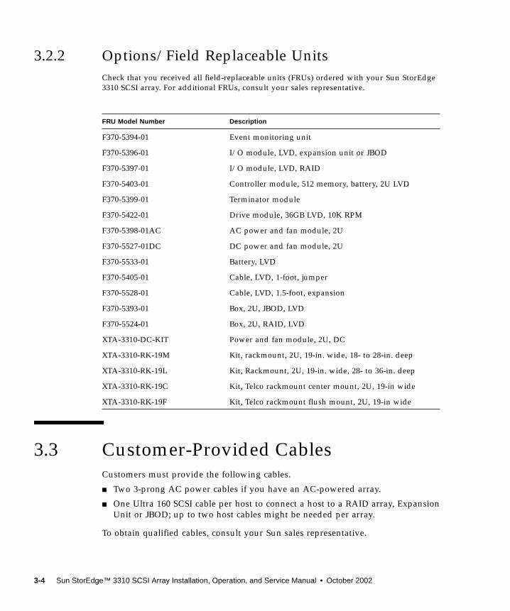
3.2.2 Options/Field Replaceable UnitsCheck that you received all field-replaceable units (FRUs) ordered with your Sun StorEdge3310 SCSI array. For additional FRUs, consult your sales representative.
3.3 Customer-Provided CablesCustomers must provide the following cables.
■ Two 3-prong AC power cables if you have an AC-powered array.
■ One Ultra 160 SCSI cable per host to connect a host to a RAID array, ExpansionUnit or JBOD; up to two host cables might be needed per array.
To obtain qualified cables, consult your Sun sales representative.
FRU Model Number Description
F370-5394-01 Event monitoring unit
F370-5396-01 I/O module, LVD, expansion unit or JBOD
F370-5397-01 I/O module, LVD, RAID
F370-5403-01 Controller module, 512 memory, battery, 2U LVD
F370-5399-01 Terminator module
F370-5422-01 Drive module, 36GB LVD, 10K RPM
F370-5398-01AC AC power and fan module, 2U
F370-5527-01DC DC power and fan module, 2U
F370-5533-01 Battery, LVD
F370-5405-01 Cable, LVD, 1-foot, jumper
F370-5528-01 Cable, LVD, 1.5-foot, expansion
F370-5393-01 Box, 2U, JBOD, LVD
F370-5524-01 Box, 2U, RAID, LVD
XTA-3310-DC-KIT Power and fan module, 2U, DC
XTA-3310-RK-19M Kit, rackmount, 2U, 19-in. wide, 18- to 28-in. deep
XTA-3310-RK-19L Kit, Rackmount, 2U, 19-in. wide, 28- to 36-in. deep
XTA-3310-RK-19C Kit, Telco rackmount center mount, 2U, 19-in wide
XTA-3310-RK-19F Kit, Telco rackmount flush mount, 2U, 19-in wide
3-4 Sun StorEdge™ 3310 SCSI Array Installation, Operation, and Service Manual • October 2002
CHAPTER 4
Rackmounting
This chapter describes the two types of rackmount equipment available to purchaseand install. The array is easily installed into a rack or cabinet.
Topics covered in this chapter are:
■ “Required Site and Chassis Preparation” on page 4-2■ “Cabinet Mounting” on page 4-3■ “Telco Rackmounting” on page 4-9
■ “Flushmount Configuration” on page 4-10■ “Center-of-Gravity Configuration” on page 4-13
■ “Powering Up and Checking LEDs” on page 4-16
4-1
4.1 Required Site and Chassis Preparation
Tip – These instructions can save you a lot of time read them carefully. The entireassembly procedure should take less than thirty minutes if you follow all theinstructions provided.
Before rackmounting, be sure to check your site location and confirm that you havecables with adequate lengths to connect to servers and to power outlets.
Caution – We recommend that two people install each Sun StorEdge 3310 SCSIarray. If you only have one person to perform the installation, you should removethe power supplies and hard disk drives before installing the array, and if possibleposition the array on top of another device or shelf in the rack to hold the unit asyou attach all the brackets.
Caution – Do not use any power tools with any procedures. Power tools may stripor damage connections.
Note – To reduce the weight of the array during the rackmounting procedure, see“Installing Spares and FRUs” on page 9-1 for instructions on removing drives orpower supplies. A fully populated array weighs over 50 pounds; an array withoutdrives and power supplies weighs about 30 pounds.
You can now proceed with the power and cabling procedures. Perform all steps inthe order given.
The following tools are used to complete this procedure:
■ Medium Phillips head screwdriver■ Allen wrenches (provided for 6 mm cap screws and #12–24 socket cap screws)
4-2 Sun StorEdge™ 3310 SCSI Array Installation, Operation, and Service Manual • October 2002
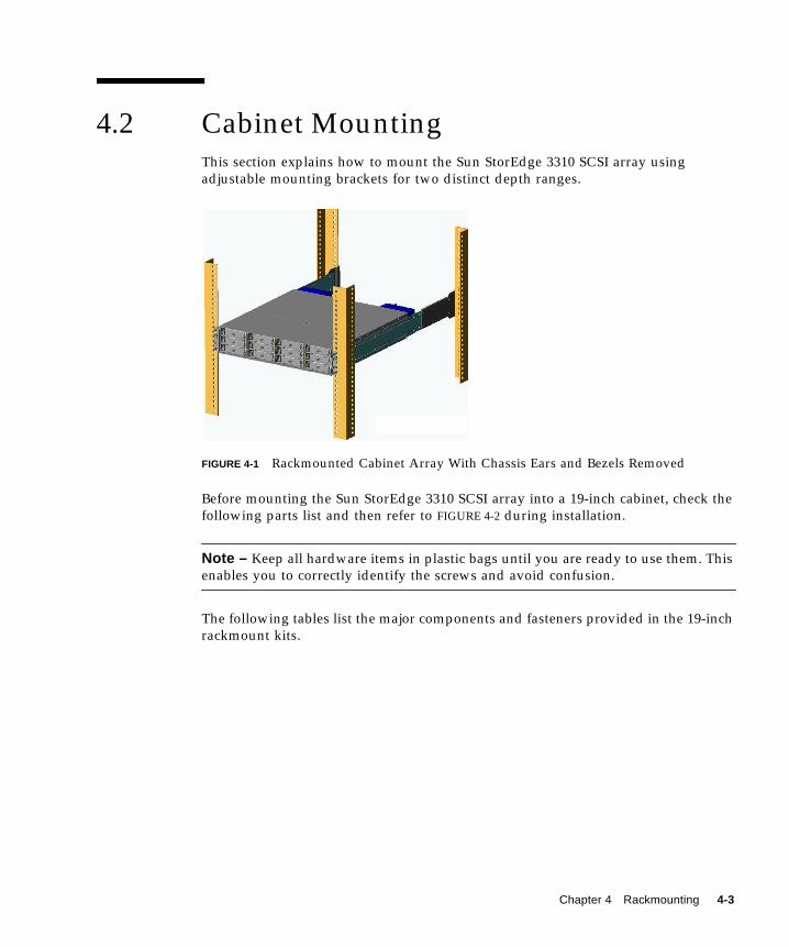
4.2 Cabinet MountingThis section explains how to mount the Sun StorEdge 3310 SCSI array usingadjustable mounting brackets for two distinct depth ranges.
FIGURE 4-1 Rackmounted Cabinet Array With Chassis Ears and Bezels Removed
Before mounting the Sun StorEdge 3310 SCSI array into a 19-inch cabinet, check thefollowing parts list and then refer to FIGURE 4-2 during installation.
Note – Keep all hardware items in plastic bags until you are ready to use them. Thisenables you to correctly identify the screws and avoid confusion.
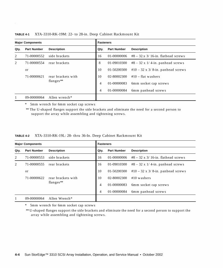
The following tables list the major components and fasteners provided in the 19-inchrackmount kits.
Chapter 4 Rackmounting 4-3
.
TABLE 4-1 XTA-3310-RK-19M: 22- to 28-in. Deep Cabinet Rackmount Kit
Major Components Fasteners
Qty. Part Number Description Qty. Part Number Description
2 71-00000552 side brackets 16 01-00000006 #8 – 32.x 3/16-in. flathead screws
2 71-00000554 rear brackets 8 01-09010300 #8 – 32 x 1/4-in. panhead screws
or 10 01-50200300 #10 – 32 x 3/8-in. panhead screws
71-00000621 rear brackets withflanges**
10 02-80002300 #10 – flat washers
4 01-00000083 6mm socket cap screws
4 01-00000084 6mm panhead screws
1 09-00000064 Allen wrench*
* 5mm wrench for 6mm socket cap screws** The U-shaped flanges support the side brackets and eliminate the need for a second person to
support the array while assembling and tightening screws.
TABLE 4-2 XTA-3310-RK-19L: 28- thru 36-In. Deep Cabinet Rackmount Kit
Major Components Fasteners
Qty. Part Number Description Qty. Part Number Description
2 71-00000553 side brackets 16 01-00000006 #8 – 32 x 3/16-in. flathead screws
2 71-00000555 rear brackets 16 01-09010300 #8 – 32 x 1/4-in. panhead screws
or 10 01-50200300 #10 – 32 x 3/8-in. panhead screws
71-00000622 rear brackets withflanges**
10 02-80002300 #10 washers
4 01-00000083 6mm socket cap screws
4 01-00000084 6mm panhead screws
1 09-00000064 Allen Wrench*
* 5mm wrench for 6mm socket cap screws** U-shaped flanges support the side brackets and eliminate the need for a second person to support the
array while assembling and tightening screws.
4-4 Sun StorEdge™ 3310 SCSI Array Installation, Operation, and Service Manual • October 2002
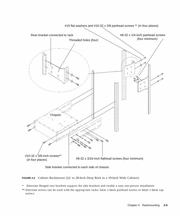
FIGURE 4-2 Cabinet Rackmount (22- to 28-Inch Deep Rack in a 19-Inch Wide Cabinet)
* Alternate flanged rear brackets support the side brackets and enable a easy one-person installation.** Alternate screws can be used with the appropriate racks: 5mm x 6mm panhead screws or 6mm x 6mm cap
screws.
(four minimum)#8-32 x 1/4-inch panhead screws
Chassis
#10 flat washers and #10-32 x 3/8 panhead screws ** (in four places)
Rear bracket connected to rack
#8-32 x 3/16-inch flathead screws (four minimum)
Side bracket connected to each side of chassis
Threaded holes (four)
#10-32 x 3/8-inch screws**(in four places)
Chapter 4 Rackmounting 4-5
Caution – Do not use any power tools with any procedures. Power tools can stripor damage connections.
1. Determine where the array will be installed.
To plan the correct location in the appropriate Sun racks, refer to the 805-4748-29Rackmount Placement Matrix (RPM) which is available at:
www.sun.com/products-n-solutions/hardware/docs/Network_Storage_Solutions/Cabinets_and_Enclosures/index.html
Install the first array at the bottom of the rack, and install each subsequent chassisabove the previous one unless otherwise indicated in the RPM manual.
2. Before rackmounting, be sure to check your site location and confirm that youhave cables with adequate lengths to connect to servers and to power outlets.
3. Remove bezel (front faceplate) and the two plastic ear caps from the front of thechassis.
Note – Keep all hardware items in plastic bags until you are ready to use them. Thisenables you to correctly identify of the screws and avoid confusion.
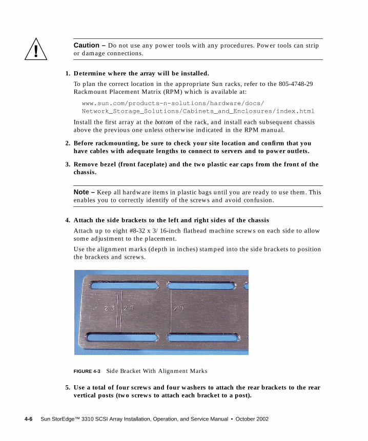
4. Attach the side brackets to the left and right sides of the chassis
Attach up to eight #8-32 x 3/16-inch flathead machine screws on each side to allowsome adjustment to the placement.
Use the alignment marks (depth in inches) stamped into the side brackets to positionthe brackets and screws.
FIGURE 4-3 Side Bracket With Alignment Marks
5. Use a total of four screws and four washers to attach the rear brackets to the rearvertical posts (two screws to attach each bracket to a post).
4-6 Sun StorEdge™ 3310 SCSI Array Installation, Operation, and Service Manual • October 2002
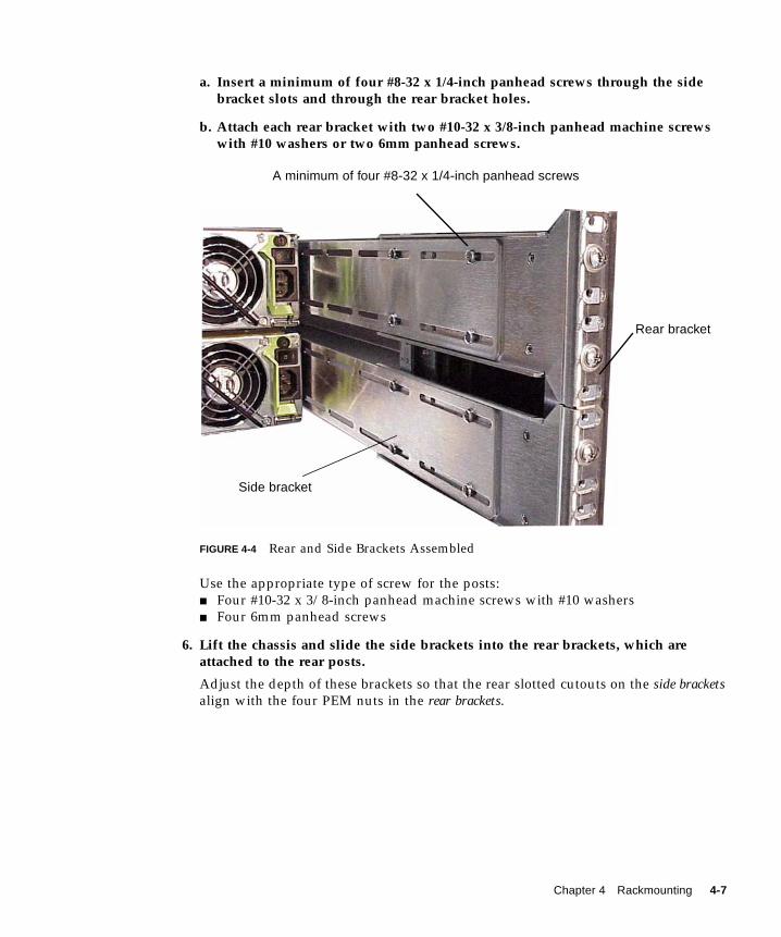
a. Insert a minimum of four #8-32 x 1/4-inch panhead screws through the sidebracket slots and through the rear bracket holes.
b. Attach each rear bracket with two #10-32 x 3/8-inch panhead machine screwswith #10 washers or two 6mm panhead screws.
FIGURE 4-4 Rear and Side Brackets Assembled
Use the appropriate type of screw for the posts:■ Four #10-32 x 3/8-inch panhead machine screws with #10 washers■ Four 6mm panhead screws
6. Lift the chassis and slide the side brackets into the rear brackets, which areattached to the rear posts.
Adjust the depth of these brackets so that the rear slotted cutouts on the side bracketsalign with the four PEM nuts in the rear brackets.
A minimum of four #8-32 x 1/4-inch panhead screws
Rear bracket
Side bracket
Chapter 4 Rackmounting 4-7
7. Attach each side bracket to a rear bracket (see FIGURE 4-4):
To connect the rear brackets and side brackets of a 22- to 28-inch deep rack, use atotal of:■ Eight #8-32 x 1/4-inch panhead screws■ Four #10-32 x 3/8-inch panhead screws■ Four #10 flat washers
To connect the rear and side brackets of a 28- to36-inch deep rack, use a minimum offour each and up to a total of:■ Sixteen #8-32 x 1/4-inch panhead screws■ Four #10-32 x 3/8-inch panhead screws■ Four #10 flat washers
8. Attach and secure the array’s front mounting ears with four appropriate screws(two screws into each ear):■ Four #10-32 x 3/8-inch panhead screws
or■ Four 6mm x6 socket cap screws
9. Remount all drives and power/fan modules into the array.
10. Attach the two plastic ear caps and the bezel back onto the front of the chassis.
11. Connect power cables to the chassis, power up, and check for proper operation ofthe LEDs.
Refer to “Powering Up and Checking LEDs” on page 4-16.
4-8 Sun StorEdge™ 3310 SCSI Array Installation, Operation, and Service Manual • October 2002
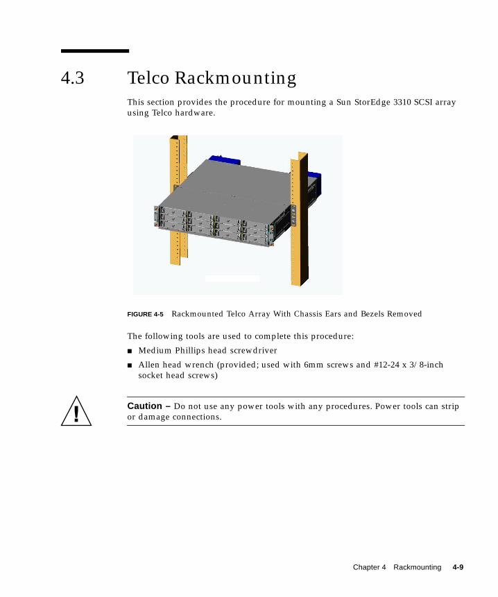
4.3 Telco RackmountingThis section provides the procedure for mounting a Sun StorEdge 3310 SCSI arrayusing Telco hardware.
FIGURE 4-5 Rackmounted Telco Array With Chassis Ears and Bezels Removed
The following tools are used to complete this procedure:
■ Medium Phillips head screwdriver
■ Allen head wrench (provided; used with 6mm screws and #12-24 x 3/8-inchsocket head screws)
Caution – Do not use any power tools with any procedures. Power tools can stripor damage connections.
Chapter 4 Rackmounting 4-9
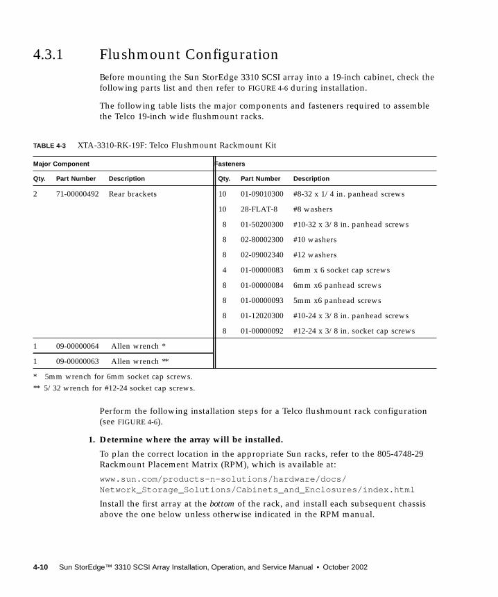
4.3.1 Flushmount ConfigurationBefore mounting the Sun StorEdge 3310 SCSI array into a 19-inch cabinet, check thefollowing parts list and then refer to FIGURE 4-6 during installation.
The following table lists the major components and fasteners required to assemblethe Telco 19-inch wide flushmount racks.
Perform the following installation steps for a Telco flushmount rack configuration(see FIGURE 4-6).
1. Determine where the array will be installed.
To plan the correct location in the appropriate Sun racks, refer to the 805-4748-29Rackmount Placement Matrix (RPM), which is available at:
www.sun.com/products-n-solutions/hardware/docs/Network_Storage_Solutions/Cabinets_and_Enclosures/index.html
Install the first array at the bottom of the rack, and install each subsequent chassisabove the one below unless otherwise indicated in the RPM manual.
TABLE 4-3 XTA-3310-RK-19F: Telco Flushmount Rackmount Kit
Major Component Fasteners
Qty. Part Number Description Qty. Part Number Description
2 71-00000492 Rear brackets 10 01-09010300 #8-32 x 1/4 in. panhead screws
10 28-FLAT-8 #8 washers
8 01-50200300 #10-32 x 3/8 in. panhead screws
8 02-80002300 #10 washers
8 02-09002340 #12 washers
4 01-00000083 6mm x 6 socket cap screws
8 01-00000084 6mm x6 panhead screws
8 01-00000093 5mm x6 panhead screws
8 01-12020300 #10-24 x 3/8 in. panhead screws
8 01-00000092 #12-24 x 3/8 in. socket cap screws
1 09-00000064 Allen wrench *
1 09-00000063 Allen wrench **
* 5mm wrench for 6mm socket cap screws.** 5/32 wrench for #12-24 socket cap screws.
4-10 Sun StorEdge™ 3310 SCSI Array Installation, Operation, and Service Manual • October 2002
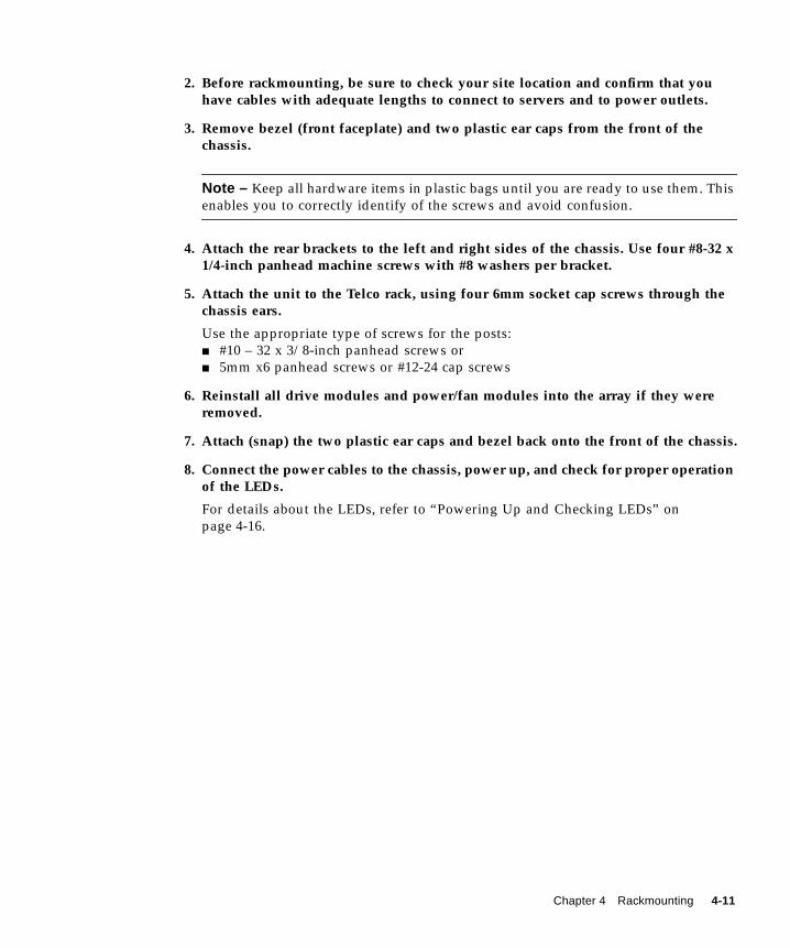
2. Before rackmounting, be sure to check your site location and confirm that youhave cables with adequate lengths to connect to servers and to power outlets.
3. Remove bezel (front faceplate) and two plastic ear caps from the front of thechassis.
Note – Keep all hardware items in plastic bags until you are ready to use them. Thisenables you to correctly identify of the screws and avoid confusion.
4. Attach the rear brackets to the left and right sides of the chassis. Use four #8-32 x1/4-inch panhead machine screws with #8 washers per bracket.
5. Attach the unit to the Telco rack, using four 6mm socket cap screws through thechassis ears.
Use the appropriate type of screws for the posts:■ #10 – 32 x 3/8-inch panhead screws or■ 5mm x6 panhead screws or #12-24 cap screws
6. Reinstall all drive modules and power/fan modules into the array if they wereremoved.
7. Attach (snap) the two plastic ear caps and bezel back onto the front of the chassis.
8. Connect the power cables to the chassis, power up, and check for proper operationof the LEDs.
For details about the LEDs, refer to “Powering Up and Checking LEDs” onpage 4-16.
Chapter 4 Rackmounting 4-11
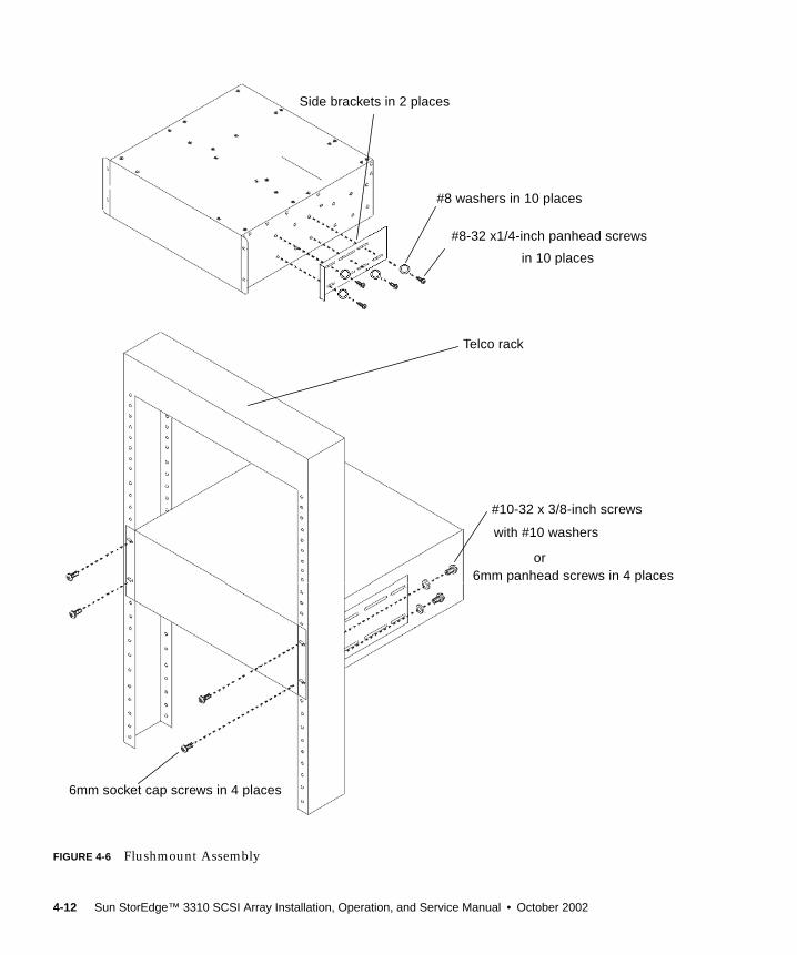
FIGURE 4-6 Flushmount Assembly
Side brackets in 2 places
#8-32 x1/4-inch panhead screws
#10-32 x 3/8-inch screws
#8 washers in 10 places
Telco rack
6mm socket cap screws in 4 places
in 10 places
with #10 washers
6mm panhead screws in 4 placesor
4-12 Sun StorEdge™ 3310 SCSI Array Installation, Operation, and Service Manual • October 2002
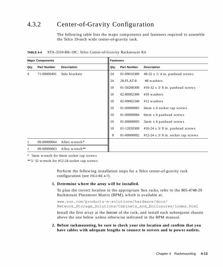
4.3.2 Center-of-Gravity ConfigurationThe following table lists the major components and fasteners required to assemblethe Telco 19-inch wide center-of-gravity rack.
Perform the following installation steps for a Telco center-of-gravity rackconfiguration (see FIGURE 4-7).
1. Determine where the array will be installed.
To plan the correct location in the appropriate Sun racks, refer to the 805-4748-29Rackmount Placement Matrix (RPM), which is available at:
www.sun.com/products-n-solutions/hardware/docs/Network_Storage_Solutions/Cabinets_and_Enclosures/index.html
Install the first array at the bottom of the rack, and install each subsequent chassisabove the one below unless otherwise indicated in the RPM manual.
2. Before rackmounting, be sure to check your site location and confirm that youhave cables with adequate lengths to connect to servers and to power outlets.
TABLE 4-4 XTA-3310-RK-19C: Telco Center-of-Gravity Rackmount Kit
Major Components Fasteners
Qty. Part Number Description Qty. Part Number Description
4 71-00000491 Side brackets 24 01-09010300 #8-32 x 1/4 in. panhead screws
24 28-FLAT-8 #8 washers
10 01-50200300 #10-32 x 3/8 in. panhead screws
10 02-80002300 #10 washers
10 02-09002340 #12 washers
10 01-00000083 6mm x 6 socket cap screws
10 01-00000084 6mm x 6 panhead screws
10 01-00000093 5mm x 6 panhead screws
10 01-12020300 #10-24 x 3/8 in. panhead screws
8 01-00000092 #12-24 x 3/8 in. socket cap screws
1 09-00000064 Allen wrench*
1 09-00000063 Allen wrench**
* 5mm wrench for 6mm socket cap screws** 5/32 wrench for #12-24 socket cap screws
Chapter 4 Rackmounting 4-13
Note – Keep all hardware items in plastic bags until you are ready to use them. Thisenables you to correctly identity of the screw sizes and avoid confusion.
3. Remove the bezel (front faceplate) and two plastic ear caps from the front of thechassis.
4. Attach the two side brackets to each side of the chassis:
Allow for the depth of the rack, and allow for the distance you want the chassis toextend forward in the rack. Attach the front brackets first.
Use up to six #8-32 x 1/4-inch panhead machine screws for each front side bracket,using the mounting holes available. (Use four screws as a minimum.) Then mountthe front brackets to the Telco rack using step 5.
Next, use four #8-32 x 1/4-inch panhead screws with #8 washers for each rear sidebracket, and use step 5 to mount to Telco rack.
5. Attach the chassis to the Telco rack, by inserting eight or more 6mm screwsthrough the mounting holes located on both sides of the brackets and into theframe.
Use the appropriate type of screws for the ports:■ #10 – 32 x 3/8-inch panhead screws with #8 washers or■ 5mm x6 panhead screws or #12-24 cap screws
6. Reinstall all drive modules and power/fan modules into the array if they wereremoved.
7. Attach (snap) the two plastic ear caps and the bezel back onto the front of thechassis.
8. Connect power cables to the chassis, power up, and check for proper operation ofthe LEDs.
For details about the LEDs, refer to “Powering Up and Checking LEDs” onpage 4-16.
4-14 Sun StorEdge™ 3310 SCSI Array Installation, Operation, and Service Manual • October 2002
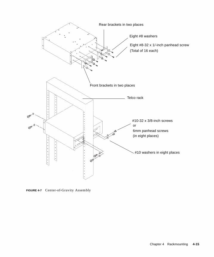
FIGURE 4-7 Center-of-Gravity Assembly
Eight #8 washers
#10-32 x 3/8-inch screws
Rear brackets in two places
Telco rack
Front brackets in two places
#10 washers in eight places
Eight #8-32 x 1/-inch panhead screws
(Total of 16 each)
or
6mm panhead screws(in eight places)
Chapter 4 Rackmounting 4-15
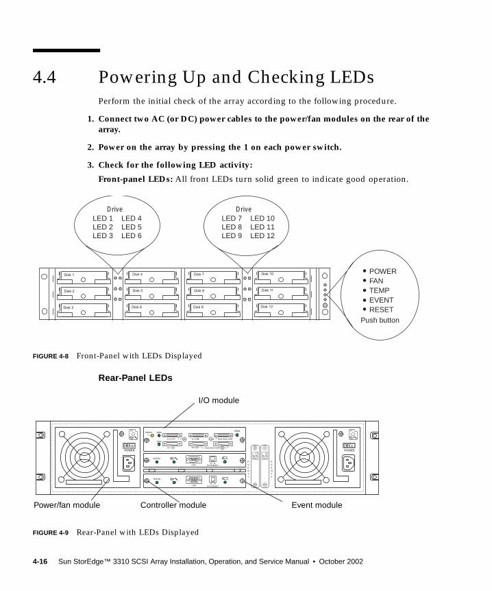
4.4 Powering Up and Checking LEDsPerform the initial check of the array according to the following procedure.
1. Connect two AC (or DC) power cables to the power/fan modules on the rear of thearray.
2. Power on the array by pressing the 1 on each power switch.
3. Check for the following LED activity:
Front-panel LEDs: All front LEDs turn solid green to indicate good operation.
FIGURE 4-8 Front-Panel with LEDs Displayed
Rear-Panel LEDs
FIGURE 4-9 Rear-Panel with LEDs Displayed
Disk 1
Disk 2
Disk 3
Disk 4
Disk 5
Disk 6
Disk 7
Disk 8
Disk 9
Disk 10
Disk 11
Disk 12
DriveLED 1LED 2LED 3
LED 4LED 5LED 6
DriveLED 7LED 8LED 9
LED 10LED 11LED 12
POWERFANTEMPEVENTRESET
Push button
POWER
COM 10/100 BASE-T
ERROR TERM
SNGLCH 0
CH 1
CH 3
CH 2
SNGL BUS CONF
DUAL BUS CONF
TERM
DB
SB SB
EVENT 1
EVENT 2
POWER
Activity
< >...+
COM 10/100 BASE-T
Activity
< >...+
PS PS
EMUEMU
I/O module
Power/fan module Controller module Event module
4-16 Sun StorEdge™ 3310 SCSI Array Installation, Operation, and Service Manual • October 2002
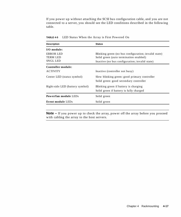
If you power up without attaching the SCSI bus configuration cable, and you are notconnected to a server, you should see the LED conditions described in the followingtable.
Note – If you power up to check the array, power off the array before you proceedwith cabling the array to the host servers.
TABLE 4-5 LED Status When the Array is First Powered On
Description Status
I/O module:ERROR LEDTERM LEDSNGL LED
Blinking green (no bus configuration; invalid state)Solid green (auto termination enabled)Inactive (no bus configuration; invalid state)
Controller module:ACTIVITY Inactive (controller not busy)
Center LED (status symbol) Slow blinking green: good primary controllerSolid green: good secondary controller
Right-side LED (battery symbol) Blinking green if battery is chargingSolid green if battery is fully charged
Power/fan module LEDs Solid green
Event module LEDs Solid green
Chapter 4 Rackmounting 4-17

4-18 Sun StorEdge™ 3310 SCSI Array Installation, Operation, and Service Manual • October 2002
CHAPTER 5
Connecting Ports
This chapter provides procedures for cabling the Sun StorEdge 3310 SCSI array forsingle or dual bus configurations and for connecting the array to power and tonetwork devices.
The topics covered in this chapter are as follows:
■ “Connecting Chassis to an AC Power Outlet” on page 5-3■ “Connecting the Chassis to DC Power Outlets” on page 5-4■ “Reviewing Single Versus Dual Drive-Bus Configurations” on page 5-5■ “Connecting Cables for a Single Bus Configuration” on page 5-8■ “Connecting Cables for a Dual Bus Configuration” on page 5-11■ “Connecting SCSI Ports to Host(s)” on page 5-14■ “Cabling Configurations with Two Expansion Units” on page 5-16■ “Connecting COM Port to a VT100 Terminal or Solaris Workstation” on page 5-18■ “Connecting Ethernet Ports to LAN/WAN (Optional)” on page 5-18
Before you connect the Sun StorEdge 3310 SCSI array to the network, position theSun StorEdge 3310 SCSI array in the rack or in a location where it will reside on thenetwork.
Caution – When positioning the array, do not block the air vents at the front or backof the unit. Follow all safety precautions specified in the Sun StorEdge 3310 Safety,Regulatory, and Compliance Manual.
Caution – When you power off the array, wait five seconds before you power itback on. If you power the array off and on too quickly, a race condition might occur.
5-1
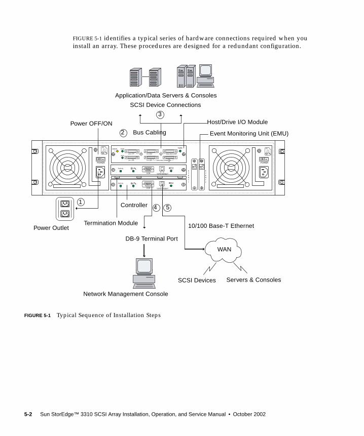
FIGURE 5-1 identifies a typical series of hardware connections required when youinstall an array. These procedures are designed for a redundant configuration.
FIGURE 5-1 Typical Sequence of Installation Steps
EVENT 1
EVENT 2
COM 10/100 BASE-T
Activity
< >...+
COM 10/100 BASE-T
Activity
< >...+
POWER POWER
ERROR TERM
SNGLCH 0
CH 1
CH 3
CH 2
SNGL BUS CONF
DUAL BUS CONF
TERM
DB
SB SB
PSPS
EMUEMU
WAN
Servers & ConsolesSCSI Devices
Network Management Console
DB-9 Terminal Port
Power OutletTermination Module
Controller
10/100 Base-T Ethernet
Power OFF/ON
SCSI Device Connections
Application/Data Servers & Consoles
Host/Drive I/O Module
Event Monitoring Unit (EMU)
54
3
1
2 Bus Cabling
5-2 Sun StorEdge™ 3310 SCSI Array Installation, Operation, and Service Manual • October 2002
5.1 Connecting Chassis to an AC PowerOutletWhen you connect the AC power cords, you should install the provided two cordlocks at the same time. To connect the AC power cords, perform the followingprocedure.
1. Connect an appropriate AC power cable to the first power supply and to a poweroutlet.
The provided AC cord locks are used to securely fasten the AC cable connectors.
Caution – For AC power: If the array is connected to AC power sources not withinthe designated 90–135, 180–265 VAC PFC range, damage might occur to the unit.
Note – To ensure power redundancy, be sure to connect the two power supplymodules to two separate circuits (for example, one commercial circuit and one UPS).
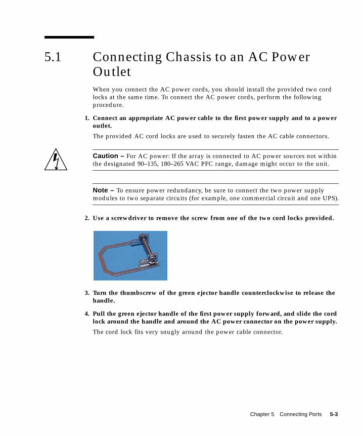
2. Use a screwdriver to remove the screw from one of the two cord locks provided.
3. Turn the thumbscrew of the green ejector handle counterclockwise to release thehandle.
4. Pull the green ejector handle of the first power supply forward, and slide the cordlock around the handle and around the AC power connector on the power supply.
The cord lock fits very snugly around the power cable connector.
Chapter 5 Connecting Ports 5-3
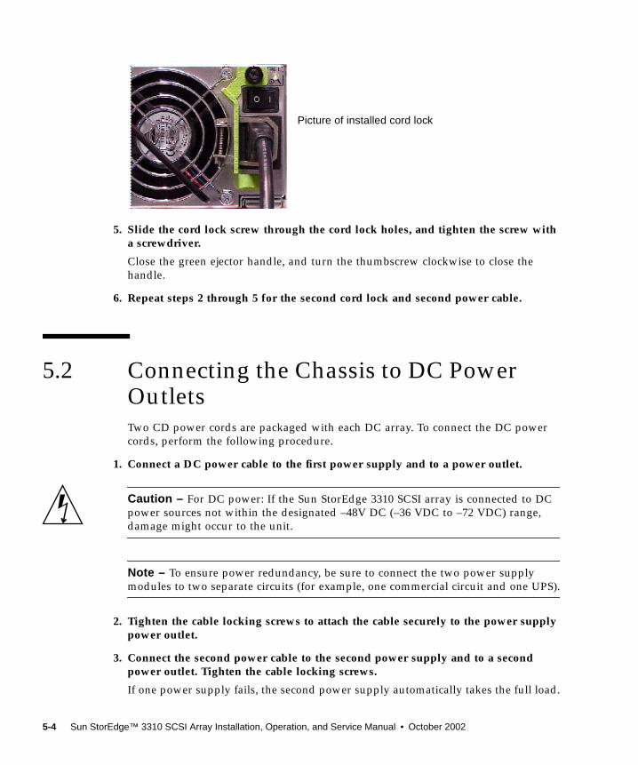
5. Slide the cord lock screw through the cord lock holes, and tighten the screw witha screwdriver.
Close the green ejector handle, and turn the thumbscrew clockwise to close thehandle.
6. Repeat steps 2 through 5 for the second cord lock and second power cable.
5.2 Connecting the Chassis to DC PowerOutletsTwo CD power cords are packaged with each DC array. To connect the DC powercords, perform the following procedure.
1. Connect a DC power cable to the first power supply and to a power outlet.
Caution – For DC power: If the Sun StorEdge 3310 SCSI array is connected to DCpower sources not within the designated –48V DC (–36 VDC to –72 VDC) range,damage might occur to the unit.
Note – To ensure power redundancy, be sure to connect the two power supplymodules to two separate circuits (for example, one commercial circuit and one UPS).
2. Tighten the cable locking screws to attach the cable securely to the power supplypower outlet.
3. Connect the second power cable to the second power supply and to a secondpower outlet. Tighten the cable locking screws.
If one power supply fails, the second power supply automatically takes the full load.
Picture of installed cord lock
5-4 Sun StorEdge™ 3310 SCSI Array Installation, Operation, and Service Manual • October 2002
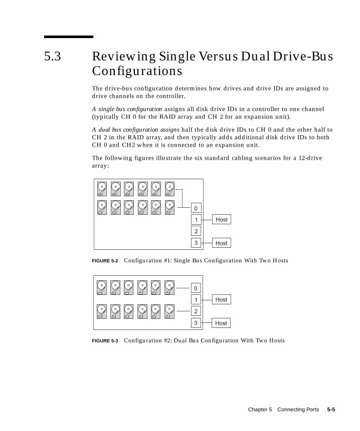
5.3 Reviewing Single Versus Dual Drive-BusConfigurationsThe drive-bus configuration determines how drives and drive IDs are assigned todrive channels on the controller.
A single bus configuration assigns all disk drive IDs in a controller to one channel(typically CH 0 for the RAID array and CH 2 for an expansion unit).
A dual bus configuration assigns half the disk drive IDs to CH 0 and the other half toCH 2 in the RAID array, and then typically adds additional disk drive IDs to bothCH 0 and CH2 when it is connected to an expansion unit.
The following figures illustrate the six standard cabling scenarios for a 12-drivearray:
FIGURE 5-2 Configuration #1: Single Bus Configuration With Two Hosts
FIGURE 5-3 Configuration #2: Dual Bus Configuration With Two Hosts
0
1
2
3
Host
Host
0
1
2
3
Host
Host
Chapter 5 Connecting Ports 5-5
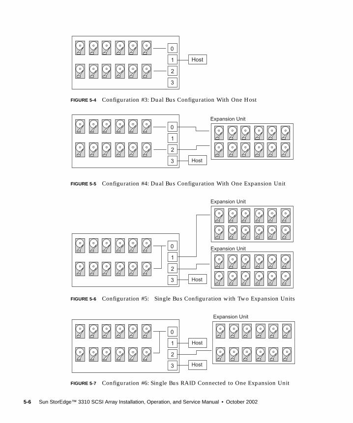
FIGURE 5-4 Configuration #3: Dual Bus Configuration With One Host
FIGURE 5-5 Configuration #4: Dual Bus Configuration With One Expansion Unit
FIGURE 5-6 Configuration #5: Single Bus Configuration with Two Expansion Units
FIGURE 5-7 Configuration #6: Single Bus RAID Connected to One Expansion Unit
0
1
2
3
Host
0
1
2
3 Host
Expansion Unit
0
1
2
3 Host
Expansion Unit
Expansion Unit
0
1
2
3 Host
Host
Expansion Unit
5-6 Sun StorEdge™ 3310 SCSI Array Installation, Operation, and Service Manual • October 2002
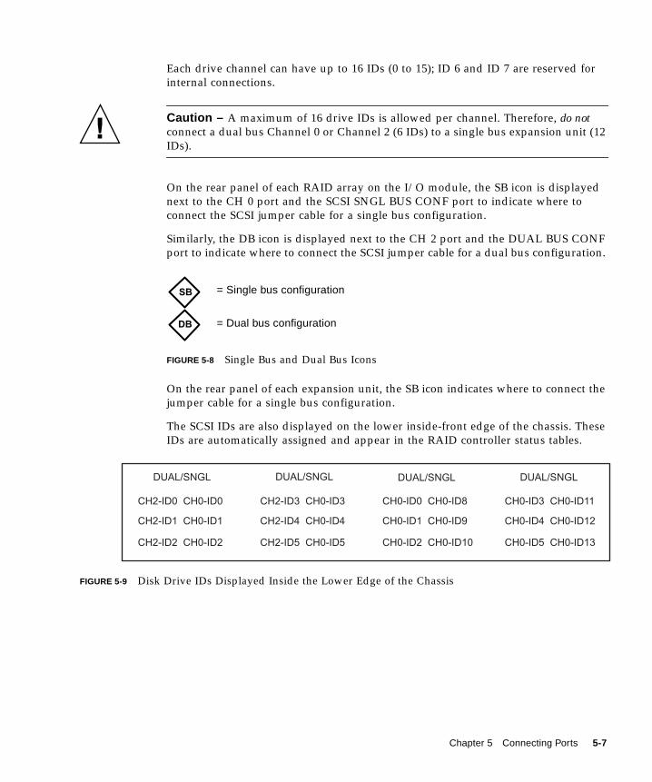
Each drive channel can have up to 16 IDs (0 to 15); ID 6 and ID 7 are reserved forinternal connections.
Caution – A maximum of 16 drive IDs is allowed per channel. Therefore, do notconnect a dual bus Channel 0 or Channel 2 (6 IDs) to a single bus expansion unit (12IDs).
On the rear panel of each RAID array on the I/O module, the SB icon is displayednext to the CH 0 port and the SCSI SNGL BUS CONF port to indicate where toconnect the SCSI jumper cable for a single bus configuration.
Similarly, the DB icon is displayed next to the CH 2 port and the DUAL BUS CONFport to indicate where to connect the SCSI jumper cable for a dual bus configuration.
FIGURE 5-8 Single Bus and Dual Bus Icons
On the rear panel of each expansion unit, the SB icon indicates where to connect thejumper cable for a single bus configuration.
The SCSI IDs are also displayed on the lower inside-front edge of the chassis. TheseIDs are automatically assigned and appear in the RAID controller status tables.
FIGURE 5-9 Disk Drive IDs Displayed Inside the Lower Edge of the Chassis
SB
DB
= Single bus configuration
= Dual bus configuration
DUAL/SNGL DUAL/SNGL DUAL/SNGL DUAL/SNGL
CH2-ID0 CH0-ID0
CH2-ID1 CH0-ID1
CH2-ID2 CH0-ID2
CH2-ID3 CH0-ID3
CH2-ID4 CH0-ID4
CH2-ID5 CH0-ID5
CH0-ID0 CH0-ID8
CH0-ID1 CH0-ID9
CH0-ID2 CH0-ID10
CH0-ID3 CH0-ID11
CH0-ID4 CH0-ID12
CH0-ID5 CH0-ID13
Chapter 5 Connecting Ports 5-7
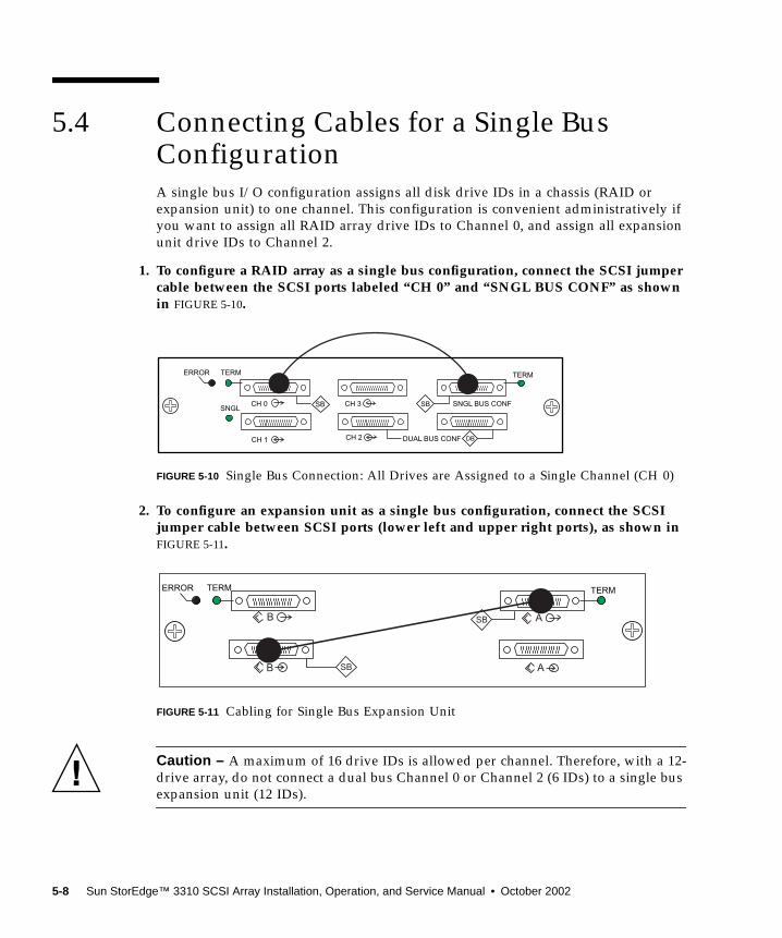
5.4 Connecting Cables for a Single BusConfigurationA single bus I/O configuration assigns all disk drive IDs in a chassis (RAID orexpansion unit) to one channel. This configuration is convenient administratively ifyou want to assign all RAID array drive IDs to Channel 0, and assign all expansionunit drive IDs to Channel 2.
1. To configure a RAID array as a single bus configuration, connect the SCSI jumpercable between the SCSI ports labeled “CH 0” and “SNGL BUS CONF” as shownin FIGURE 5-10.
FIGURE 5-10 Single Bus Connection: All Drives are Assigned to a Single Channel (CH 0)
2. To configure an expansion unit as a single bus configuration, connect the SCSIjumper cable between SCSI ports (lower left and upper right ports), as shown inFIGURE 5-11.
FIGURE 5-11 Cabling for Single Bus Expansion Unit
Caution – A maximum of 16 drive IDs is allowed per channel. Therefore, with a 12-drive array, do not connect a dual bus Channel 0 or Channel 2 (6 IDs) to a single busexpansion unit (12 IDs).
SNGLCH 0
CH 1
CH 3
CH 2
SNGL BUS CONF
DUAL BUS CONF DB
SB SB
ERROR TERM TERM
AB
B
TERMERROR TERM
SB
SB A
5-8 Sun StorEdge™ 3310 SCSI Array Installation, Operation, and Service Manual • October 2002
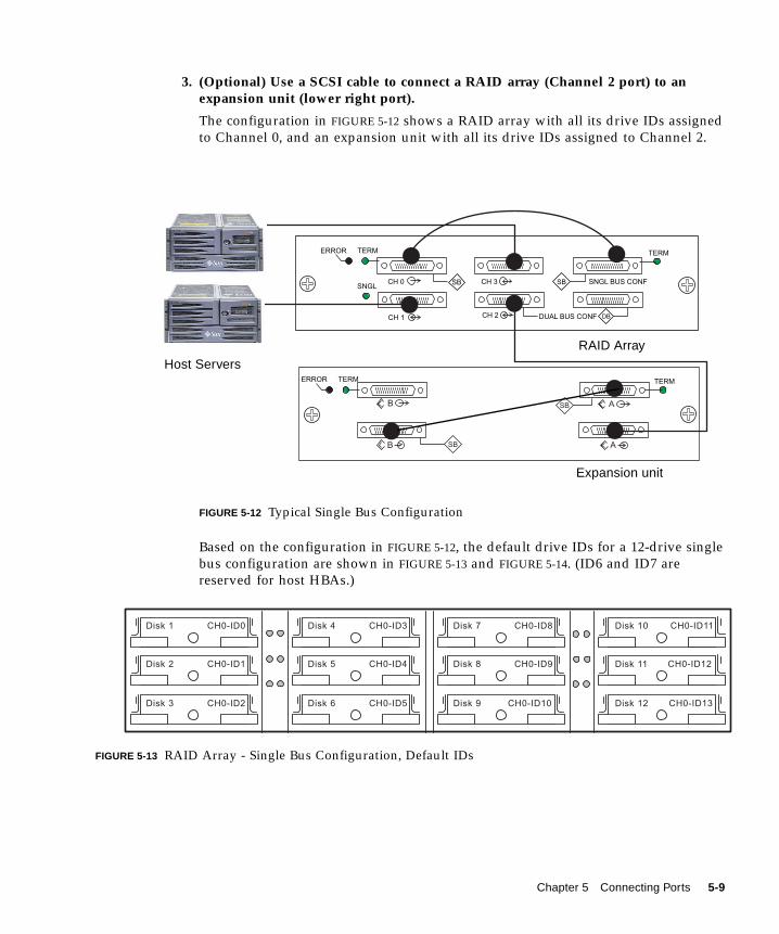
3. (Optional) Use a SCSI cable to connect a RAID array (Channel 2 port) to anexpansion unit (lower right port).
The configuration in FIGURE 5-12 shows a RAID array with all its drive IDs assignedto Channel 0, and an expansion unit with all its drive IDs assigned to Channel 2.
FIGURE 5-12 Typical Single Bus Configuration
Based on the configuration in FIGURE 5-12, the default drive IDs for a 12-drive singlebus configuration are shown in FIGURE 5-13 and FIGURE 5-14. (ID6 and ID7 arereserved for host HBAs.)
FIGURE 5-13 RAID Array - Single Bus Configuration, Default IDs
SNGLCH 0
CH 1
CH 3
CH 2
SNGL BUS CONF
DUAL BUS CONF DB
SB SB
AB
B
TERMERROR TERM
SB
SB
ERROR TERM TERM
A
Host Servers
RAID Array
Expansion unit
Disk 1 CH0-ID8
Disk 2 CH0-ID1
Disk 3 CH0-ID2
Disk 4 CH0-ID3
Disk 5 CH0-ID4
Disk 6 CH0-ID5
Disk 7
CH0-ID9Disk 8
CH0-ID10Disk 9
CH0-ID11Disk 10
CH0-ID12Disk 11
CH0-ID13Disk 12
CH0-ID0
Chapter 5 Connecting Ports 5-9
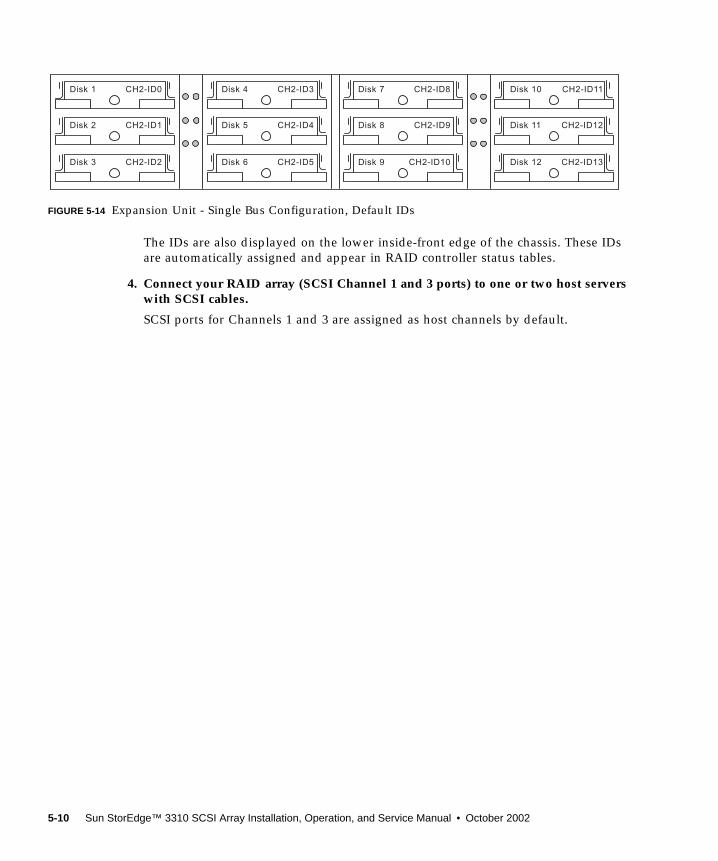
FIGURE 5-14 Expansion Unit - Single Bus Configuration, Default IDs
The IDs are also displayed on the lower inside-front edge of the chassis. These IDsare automatically assigned and appear in RAID controller status tables.
4. Connect your RAID array (SCSI Channel 1 and 3 ports) to one or two host serverswith SCSI cables.
SCSI ports for Channels 1 and 3 are assigned as host channels by default.
Disk 1 CH2-ID8
Disk 2 CH2-ID1
Disk 3 CH2-ID2
Disk 4 CH2-ID3
Disk 5 CH2-ID4
Disk 6 CH2-ID5
Disk 7
CH2-ID9Disk 8
CH2-ID10Disk 9
CH2-ID11Disk 10
CH2-ID12Disk 11
CH2-ID13Disk 12
CH2-ID0
5-10 Sun StorEdge™ 3310 SCSI Array Installation, Operation, and Service Manual • October 2002
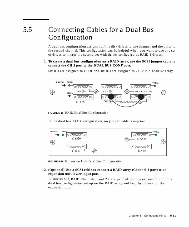
5.5 Connecting Cables for a Dual BusConfigurationA dual bus configuration assigns half the disk drives to one channel and the other tothe second channel. This configuration can be helpful when you want to use one setof drives to mirror the second set with drives configured as RAID 1 drives.
1. To create a dual bus configuration on a RAID array, use the SCSI jumper cable toconnect the CH 2 port to the DUAL BUS CONF port.
Six IDs are assigned to CH 0, and six IDs are assigned to CH 2 in a 12-drive array.
FIGURE 5-15 RAID Dual Bus Configuration
In the dual bus JBOD configuration, no jumper cable is required.
FIGURE 5-16 Expansion Unit Dual Bus Configuration
2. (Optional) Use a SCSI cable to connect a RAID array (Channel 2 port) to anexpansion unit lower input port.
In FIGURE 5-17, RAID Channels 0 and 2 are expanded into the expansion unit, in adual bus configuration set up on the RAID array and kept by default for theexpansion unit.
SNGLCH 0
CH 1
CH 3
CH 2
SNGL BUS CONF
DUAL BUS CONF DB
SB SB
ERROR TERM TERM
AB
B
TERMERROR TERM
SB
SB A
Chapter 5 Connecting Ports 5-11
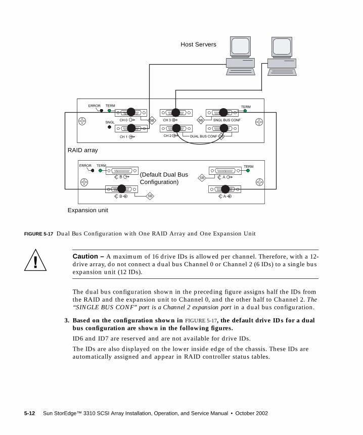
FIGURE 5-17 Dual Bus Configuration with One RAID Array and One Expansion Unit
Caution – A maximum of 16 drive IDs is allowed per channel. Therefore, with a 12-drive array, do not connect a dual bus Channel 0 or Channel 2 (6 IDs) to a single busexpansion unit (12 IDs).
The dual bus configuration shown in the preceding figure assigns half the IDs fromthe RAID and the expansion unit to Channel 0, and the other half to Channel 2. The“SINGLE BUS CONF” port is a Channel 2 expansion port in a dual bus configuration.
3. Based on the configuration shown in FIGURE 5-17, the default drive IDs for a dualbus configuration are shown in the following figures.
ID6 and ID7 are reserved and are not available for drive IDs.
The IDs are also displayed on the lower inside edge of the chassis. These IDs areautomatically assigned and appear in RAID controller status tables.
SNGLCH 0
CH 1
CH 3
CH 2
SNGL BUS CONF
DUAL BUS CONF DB
SB SB
AB
B
TERMERROR TERM
SB
SB
ERROR TERM TERM
A
Host Servers
(Default Dual BusConfiguration)
Expansion unit
RAID array
5-12 Sun StorEdge™ 3310 SCSI Array Installation, Operation, and Service Manual • October 2002
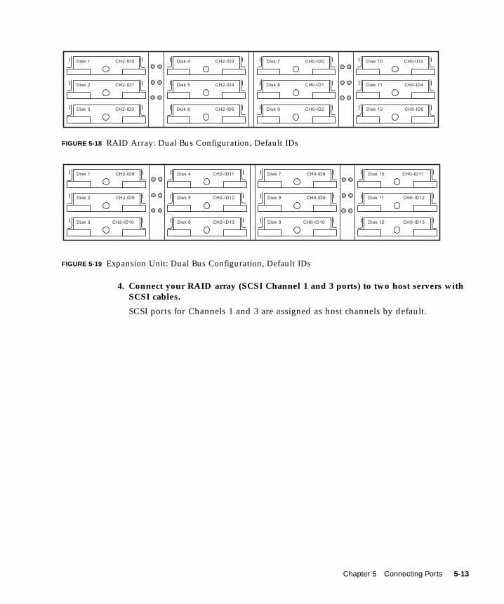
FIGURE 5-18 RAID Array: Dual Bus Configuration, Default IDs
FIGURE 5-19 Expansion Unit: Dual Bus Configuration, Default IDs
4. Connect your RAID array (SCSI Channel 1 and 3 ports) to two host servers withSCSI cables.
SCSI ports for Channels 1 and 3 are assigned as host channels by default.
Disk 1 CH0-ID0
Disk 2 CH2-ID1
Disk 3 CH2-ID2
Disk 4 CH2-ID3
Disk 5 CH2-ID4
Disk 6 CH2-ID5
Disk 7
CH0-ID1Disk 8
CH0-ID2Disk 9
CH0-ID3Disk 10
CH0-ID4Disk 11
CH0-ID5Disk 12
CH2-ID0
Disk 1 CH0-ID8
Disk 2 CH2-ID9
Disk 3 CH2-ID10
Disk 4 CH2-ID11
Disk 5 CH2-ID12
Disk 6 CH2-ID13
Disk 7
CH0-ID9Disk 8
CH0-ID10Disk 9
CH0-ID11Disk 10
CH0-ID12Disk 11
CH0-ID13Disk 12
CH2-ID8
Chapter 5 Connecting Ports 5-13
5.6 Connecting SCSI Ports to Host(s)By default, channels 1 and 3 (the upper middle SCSI port and lower left SCSI port onthe I/O module) are host channels. The array can be connected to a host in one ofthe two following ways:
■ By means of a Sun StorEdge 160 MB/second PCI Dual Ultra3 SCSI host adapterpart number X6758A, installed in a host
■ By means of a qualified and supported onboard single-ended, 40 MB/secondSCSI server-embedded SCSI controller
Connect the array to one or two hosts with SCSI cables. See the Sun StorEdge 3310SCSI Array Release Notes for a list of the supported cables.
5.6.1 Sun StorEdge 3310 RAID ArrayThe SCSI specification states that the maximum bug length for Ultra3 SCSI is 25meters for point-to-point connections. The Sun StorEdge 3310 RAID array uses apoint-to-point implementation. Each channel connector is on a separate physicalSCSI bus.
Taking into account the internal bus length of.5 meters and the internal SCSI buslength of the host, the maximum SCSI cable length to each channel connector couldconceivably be around 24 meters when connected to an Ultra3 host adapter.However, the longest Ultra3 cable qualified by Sun is 10 meters in length.
When connected to single-ended host adapters, the longest support bus length perconnector is 1.5 meters.
Note – When connecting to Ultra3 host adapters, all SCSI cables must be Ultra3-qualified. See Table 1 for a list of qualified cables.
Note – If you connect two hosts to the same channel on a RAID array, you do notneed to change the scsi-initiator-id of one host adapter.
5-14 Sun StorEdge™ 3310 SCSI Array Installation, Operation, and Service Manual • October 2002
5.6.2 Sun StorEdge 3310 JBOD ArrayThe SCSI specification states that the maximum bug length for Ultra3 SCSI is 12meters for multidrop connections. The Sun StorEdge 3310 JBOD array uses amultidrop implementation. The ports on each channel are connected to the samephysical SCSI bus.
Taking into account the internal bus length of.5 meters, and the internal SCSI buslength of the host, the maximum SCSI bus length for each channel is 12 meters whenconnected to an LVD host adapter.
You must ensure that the length of all cables to any connected nodes, as well as theinternal bus length of.5 meters internal to the StorEdge 3310 JBOD array and theinternal bus length of the host, is less than 12 meters in total. Also include thejumper cable length of .3 meters if the JBOD is being used in a single busconfiguration.
The longest Ultra3 cable qualified by Sun is 10 meters in length.
When connected to single-ended host adapters, the longest supported bus length perchannel is 1.5 meters.
Note – If you connect two hosts to the same channel, you must change the scsi-initiator-id of one host adapter as described in the host adapter documentation.When either of these hosts is subsequently booted, SCSI reset warnings aredisplayed on the other host.
Chapter 5 Connecting Ports 5-15
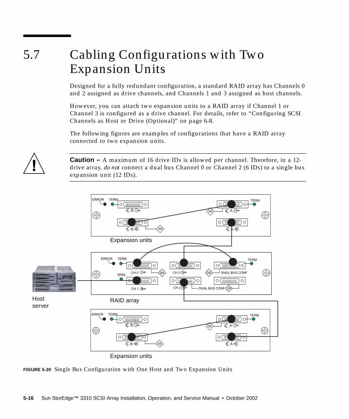
5.7 Cabling Configurations with TwoExpansion UnitsDesigned for a fully redundant configuration, a standard RAID array has Channels 0and 2 assigned as drive channels, and Channels 1 and 3 assigned as host channels.
However, you can attach two expansion units to a RAID array if Channel 1 orChannel 3 is configured as a drive channel. For details, refer to “Configuring SCSIChannels as Host or Drive (Optional)” on page 6-8.
The following figures are examples of configurations that have a RAID arrayconnected to two expansion units.
Caution – A maximum of 16 drive IDs is allowed per channel. Therefore, in a 12-drive array, do not connect a dual bus Channel 0 or Channel 2 (6 IDs) to a single busexpansion unit (12 IDs).
FIGURE 5-20 Single Bus Configuration with One Host and Two Expansion Units
SNGLCH 0
CH 1
CH 3
CH 2
SNGL BUS CONF
DUAL BUS CONF DB
SB SB
AB
B
TERMERROR TERM
SB
SB
ERROR TERM TERM
A
AB
B
TERMERROR TERM
SB
SB A
Expansion units
RAID array
Expansion units
Hostserver
5-16 Sun StorEdge™ 3310 SCSI Array Installation, Operation, and Service Manual • October 2002
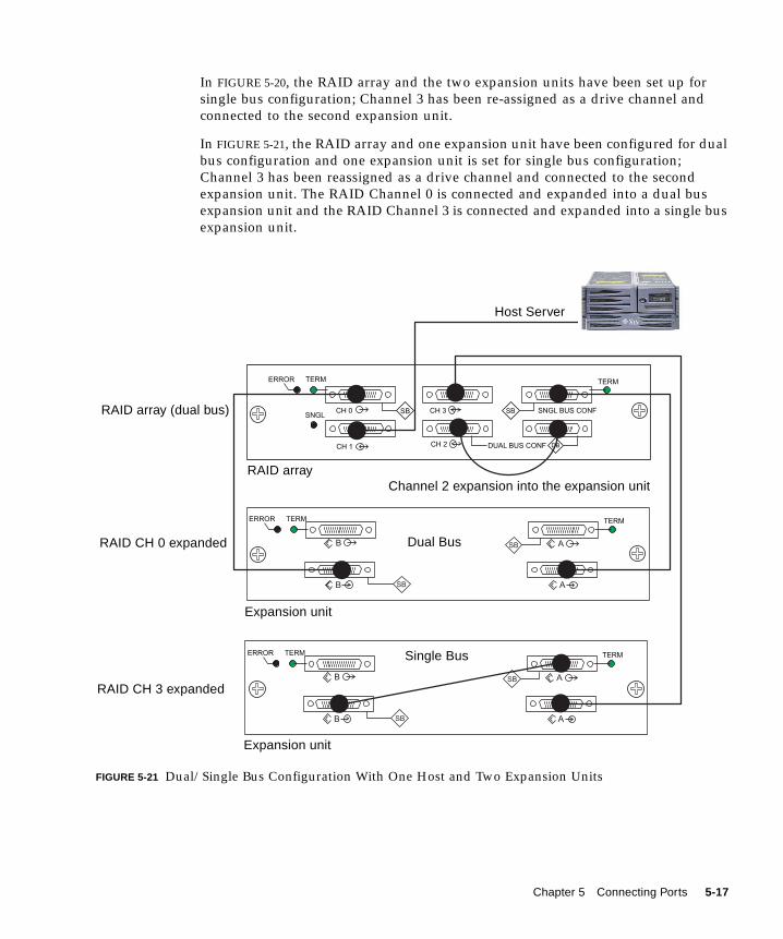
In FIGURE 5-20, the RAID array and the two expansion units have been set up forsingle bus configuration; Channel 3 has been re-assigned as a drive channel andconnected to the second expansion unit.
In FIGURE 5-21, the RAID array and one expansion unit have been configured for dualbus configuration and one expansion unit is set for single bus configuration;Channel 3 has been reassigned as a drive channel and connected to the secondexpansion unit. The RAID Channel 0 is connected and expanded into a dual busexpansion unit and the RAID Channel 3 is connected and expanded into a single busexpansion unit.
FIGURE 5-21 Dual/Single Bus Configuration With One Host and Two Expansion Units
SNGLCH 0
CH 1
CH 3
CH 2
SNGL BUS CONF
DUAL BUS CONF DB
SB SB
AB
B
TERMERROR TERM
SB
SB
ERROR TERM TERM
A
AB
B
TERMERROR TERM
SB
SB A
RAID CH 0 expanded
RAID CH 3 expanded
Channel 2 expansion into the expansion unit
Host Server
Dual Bus
RAID array
Expansion unit
Expansion unit
RAID array (dual bus)
Single Bus
Chapter 5 Connecting Ports 5-17

5.8 Connecting COM Port to a VT100Terminal or Solaris WorkstationThe RS-232 COM port on either controller module is used to configure and monitorthe RAID array. It can be connected to a VT100 terminal or terminal emulationprogram, to a terminal server, or to the serial port of a Solaris host.
1. Use a serial cable to connect the COM port of the RAID array to the serial port ona workstation/terminal server/terminal.
2. Set the serial port parameters on the workstation/ terminal server/terminal asfollows: 38400 baud, 8 bit, 1 stop bit, no parity.
For details, see “Setting Up the Serial Port Connection” on page 6-5.
5.9 Connecting Ethernet Ports toLAN/WAN (Optional)The Ethernet connection enables you to configure and monitor RAID arrays andexpansion units remotely by using the Configuration Service software. See “EthernetConnection” on page C-1 for details about the Ethernet port connection.
5-18 Sun StorEdge™ 3310 SCSI Array Installation, Operation, and Service Manual • October 2002
CHAPTER 6
First-Time Configuration
This chapter summarizes the most common procedures used for first-timeconfiguration and includes the following topics:
■ “Controller Defaults and Limitations” on page 6-2
■ “Battery Operation” on page 6-3
■ “Accessing the Management Tools” on page 6-3
■ “First-Time Controller Configuration” on page 6-4■ “Setting Up the Serial Port Connection” on page 6-5■ “Viewing the Initial Firmware Windows” on page 6-7■ “Configuring SCSI Channels as Host or Drive (Optional)” on page 6-8■ “Creating Additional Host IDs (Optional)” on page 6-10■ “Enabling a Solaris Host to Recognize New Devices and LUNs” on page 6-12■ “Reviewing Default Logical Drives and RAID Levels” on page 6-13■ “Completing Basic Configuration” on page 6-14■ “Creating Logical Drive(s) (optional)” on page 6-14■ “Changing a Logical Drive Controller Assignment (Optional)” on page 6-21■ “Partitioning a Logical Drive (optional)” on page 6-22■ “Planning for 128 LUNs (Optional)” on page 6-26■ “Mapping Logical Drive Partitions to Host LUNs” on page 6-27■ “Creating Logical Drive(s) (optional)” on page 6-14■ “Saving Configuration (NVRAM) to a Disk” on page 6-31
■ “Installing Software” on page 6-32■ “Other Supported Software” on page 6-32■ “Enabling VERITAS DMP” on page 6-32
Note – Additional management software tools are available on the supplied SunStorEdge Professional Storage Manager CD. For installation and configurationprocedures with these tools, refer to the Sun StorEdge 3310 SCSI ArrayDocumentation CD.
6-1
6.1 Controller Defaults and LimitationsThe following controller functions describe the redundant controller operation.
■ Both controllers must be exactly the same. Namely, they must operate with thesame firmware version, the same size of memory, the same number of host anddrive channels, etc. When a replacement controller is placed in a system, thefirmware of the first controller automatically synchronizes (overwrites) thefirmware of the second controller to be the same firmware.
■ In redundant mode, the maximum number of disk drive IDs on a SCSI drivechannel is 16. IDs 6 and 7 are used for host HBA connections.
■ Both controllers must be initially configured as primary controllers. Upon bootupin a redundant configuration, the controllers autonegotiate and designate onecontroller as primary and the other controller as secondary.
■ The two controllers behave as one primary controller. Once the redundantconfiguration takes effect, user configurations and settings can be done only onthe primary controller. The secondary controller then synchronizes with theconfiguration of the primary controller, making the configurations of the twocontrollers exactly the same.
The two controllers continuously monitor each other. When a controller detectsthat the other controller is not responding, the working controller immediatelytakes over and disables the failed controller.
■ It is necessary to connect all interfaces to both controllers so that the survivingcontroller can readily continue all services provided for the RAID system. Forexample, if you connect one controller to the Ethernet, you should also connectthe second controller to the Ethernet.
■ In an active-to-active configuration (standard configuration), you can assign anyappropriate logical drives to either of the controllers, and then map the logicalconfigurations to host channel IDs/LUNs. I/O requests from host computer aredirected to the primary or the secondary controller accordingly. The total drivecapacity can be grouped into several logical configurations and equally assignedto both controllers so that they share the workload.
The active-to-active configuration engages all array resources to activelymaximize performance. Users might also assign all logical configurations to onecontroller and let the other act as a standby.
■ An active-to-standby configuration is an available configuration but it is notusually selected. By assigning all the logical configurations of drives to onecontroller, the other controller stays idle and becomes active only when itscounterpart fails.
6-2 Sun StorEdge™ 3310 SCSI Array Installation, Operation, and Service Manual • October 2002
6.2 Battery OperationA battery should be changed every 2 years if the unit is continuously operated at 25degrees C and yearly at 35 degrees C or higher. The FRU shelf life for a battery is 3years.
Battery Status
The battery LED (on far right side of the controller module) is a yellow LED if thebattery is bad or missing. The LED is blinking green if the battery is charging and issolid green when the battery is fully charged.
The initial firmware screen also displays the battery status at the top of the initialscreen where BAT: status can be BAD, ----- (charging), or +++++ (fully charged).
Write Back Versus Write Through Cache Options
Unfinished writes are cached in memory in write-back mode. If power to the array isdiscontinued, data stored in the cache memory is not lost. Battery modules cansupport cache memory for several days.
Write cache is not automatically disabled when the battery is offline due to batteryfailure or a disconnected battery. You can enable or disable the write-back cachecapabilities of the RAID controller. To ensure data integrity, you may choose todisable Write Back cache option and switch to the Write Through cache optionthrough the firmware application (go to “view and edit Configuration parameters”and select “Caching Parameters”). The risk of data loss is remote.
6.3 Accessing the Management ToolsYou can manage the array through one of the following three methods:
■ With the out-of-band serial port connection, you can use a Solaris tip session ora Windows terminal emulation program to access the firmware application. Fordetails, refer to “Setting Up the Serial Port Connection” on page 6-5.
■ With the out-of-band Ethernet port connection, you can use telnet to access thefirmware application. For details, refer to “Ethernet Connection” on page C-1.
■ With in-band SCSI host connections, you can use Sun StorEdge ConfigurationService software or CLI software. Refer to the Sun StorEdge 3310 SCSIConfiguration Service User Guide for in-band setup procedures. Refer to SunStorEdge 3310 SCSI CLI Version 1.0 Guide for CLI information.
Chapter 6 First-Time Configuration 6-3
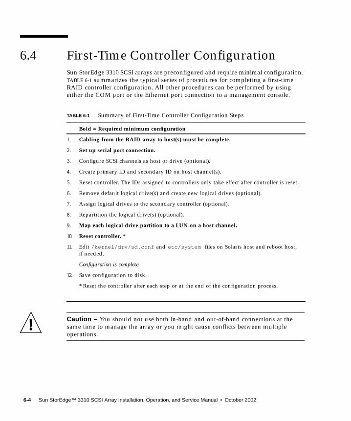
6.4 First-Time Controller ConfigurationSun StorEdge 3310 SCSI arrays are preconfigured and require minimal configuration.TABLE 6-1 summarizes the typical series of procedures for completing a first-timeRAID controller configuration. All other procedures can be performed by usingeither the COM port or the Ethernet port connection to a management console.
Caution – You should not use both in-band and out-of-band connections at thesame time to manage the array or you might cause conflicts between multipleoperations.
TABLE 6-1 Summary of First-Time Controller Configuration Steps
Bold = Required minimum configuration
1. Cabling from the RAID array to host(s) must be complete.
2. Set up serial port connection.
3. Configure SCSI channels as host or drive (optional).
4. Create primary ID and secondary ID on host channel(s).
5. Reset controller. The IDs assigned to controllers only take effect after controller is reset.
6. Remove default logical drive(s) and create new logical drives (optional).
7. Assign logical drives to the secondary controller (optional).
8. Repartition the logical drive(s) (optional).
9. Map each logical drive partition to a LUN on a host channel.
10. Reset controller. *
11. Edit /kernel/drv/sd.conf and etc/system files on Solaris host and reboot host,if needed.
Configuration is complete.
12. Save configuration to disk.
* Reset the controller after each step or at the end of the configuration process.
6-4 Sun StorEdge™ 3310 SCSI Array Installation, Operation, and Service Manual • October 2002

6.4.1 Setting Up the Serial Port ConnectionThe RAID controller can be configured by means of a Solaris workstation running aVT-100 terminal emulation program or by a Windows terminal emulation programsuch as HyperTerminal.
Note – You can also monitor and configure a RAID array over an IP network withthe Configuration Service program after you assign an IP address to the array. Fordetails, refer to “Ethernet Connection” on page C-1 and to the Sun StorEdge 3310SCSI Configuration Service User Guide.
1. Use a serial cable to connect the COM port of the RAID array to serial port b on aSolaris workstation.
A DB9-to-DB25 serial cable adapter is provided to connect the serial cable to DB25serial ports on workstations.
Make sure that a null modem cable can be attached to the host serial port. The nullmodem cable has serial signals swapped for connecting to a standard serial interface.
FIGURE 6-1 RAID Array COM Port Connected Locally to the COM Port of a Workstationor Computer Terminal
2. Power up the array.
3. Set the serial port parameters on the workstation as follows: 38400 baud, 8 bit, 1stop bit, no parity.
COM port
COM port
Chapter 6 First-Time Configuration 6-5
Accessing the Firmware Application from a Windows Host
To access the array (or a terminal server connected to the array) from a remotelylocated host, additional services must be set up on the host server to establish thehost-to-host connection.
Accessing the Firmware Application from a Solaris Host
Refer to “Redefining the Baud Rate for the tip Command” on page 6-6 for settingserial port parameters on a Solaris host.
Refer to “Using the tip Command for Local Access to the Array” on page 6-7 forinstructions on using the Solaris tip command.
Redefining the Baud Rate for the tip Command
This section describes the method for using the Solaris tip command to access thearray. Before you can use the tip command, you must redefine the baud rate.
The tip command uses the 9600 baud specified in the /etc/remote file on theSolaris host by default. The serial port of the array requires 38400 baud so you mustedit the etc/remote file and revise your use of the tip command, to use the 38400baud rate.
To edit the /etc/remote file for the 38400 baud rate, perform the following steps.
1. In the /etc/remote file, copy and edit the hardware line as follows:
Locate:
Copy the hardware line into a blank line below the hardware line, rename thehardware term as ss3000 and replace #9600 with #38400. The edited line lookslike the following line:
2. Save the file in the /etc directory.
Use the replacement term ss3000 with the tip command.
hardware: :dv=/dev/term/b:br#9600:el= . . .
ss3000: :dv=/dev/term/b:br#38400:el= . . .
6-6 Sun StorEdge™ 3310 SCSI Array Installation, Operation, and Service Manual • October 2002
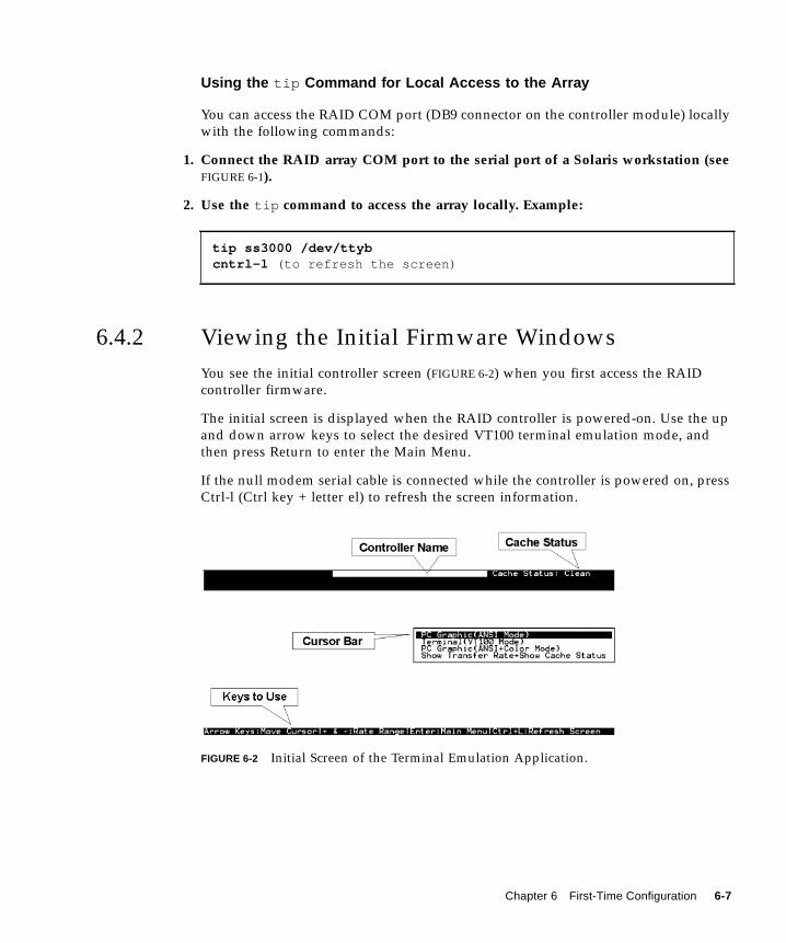
Using the tip Command for Local Access to the Array
You can access the RAID COM port (DB9 connector on the controller module) locallywith the following commands:
1. Connect the RAID array COM port to the serial port of a Solaris workstation (seeFIGURE 6-1).
2. Use the tip command to access the array locally. Example:
6.4.2 Viewing the Initial Firmware WindowsYou see the initial controller screen (FIGURE 6-2) when you first access the RAIDcontroller firmware.
The initial screen is displayed when the RAID controller is powered-on. Use the upand down arrow keys to select the desired VT100 terminal emulation mode, andthen press Return to enter the Main Menu.
If the null modem serial cable is connected while the controller is powered on, pressCtrl-l (Ctrl key + letter el) to refresh the screen information.
FIGURE 6-2 Initial Screen of the Terminal Emulation Application.
tip ss3000 /dev/ttybcntrl-l (to refresh the screen)
Chapter 6 First-Time Configuration 6-7
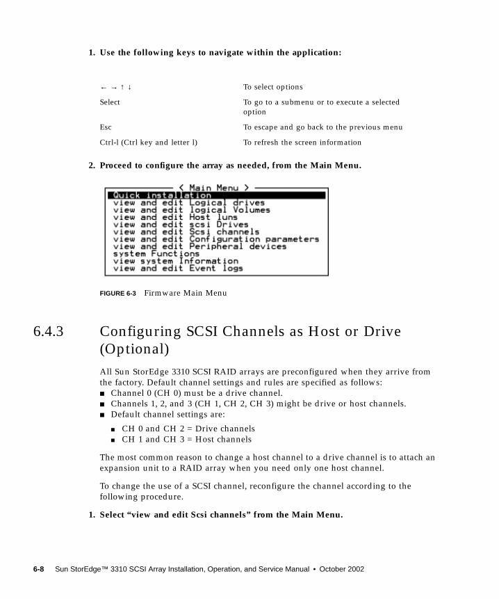
1. Use the following keys to navigate within the application:
2. Proceed to configure the array as needed, from the Main Menu.
FIGURE 6-3 Firmware Main Menu
6.4.3 Configuring SCSI Channels as Host or Drive(Optional)All Sun StorEdge 3310 SCSI RAID arrays are preconfigured when they arrive fromthe factory. Default channel settings and rules are specified as follows:■ Channel 0 (CH 0) must be a drive channel.■ Channels 1, 2, and 3 (CH 1, CH 2, CH 3) might be drive or host channels.■ Default channel settings are:
■ CH 0 and CH 2 = Drive channels■ CH 1 and CH 3 = Host channels
The most common reason to change a host channel to a drive channel is to attach anexpansion unit to a RAID array when you need only one host channel.
To change the use of a SCSI channel, reconfigure the channel according to thefollowing procedure.
1. Select “view and edit Scsi channels” from the Main Menu.
← → ↑ ↓ To select options
Select To go to a submenu or to execute a selectedoption
Esc To escape and go back to the previous menu
Ctrl-l (Ctrl key and letter l) To refresh the screen information
6-8 Sun StorEdge™ 3310 SCSI Array Installation, Operation, and Service Manual • October 2002
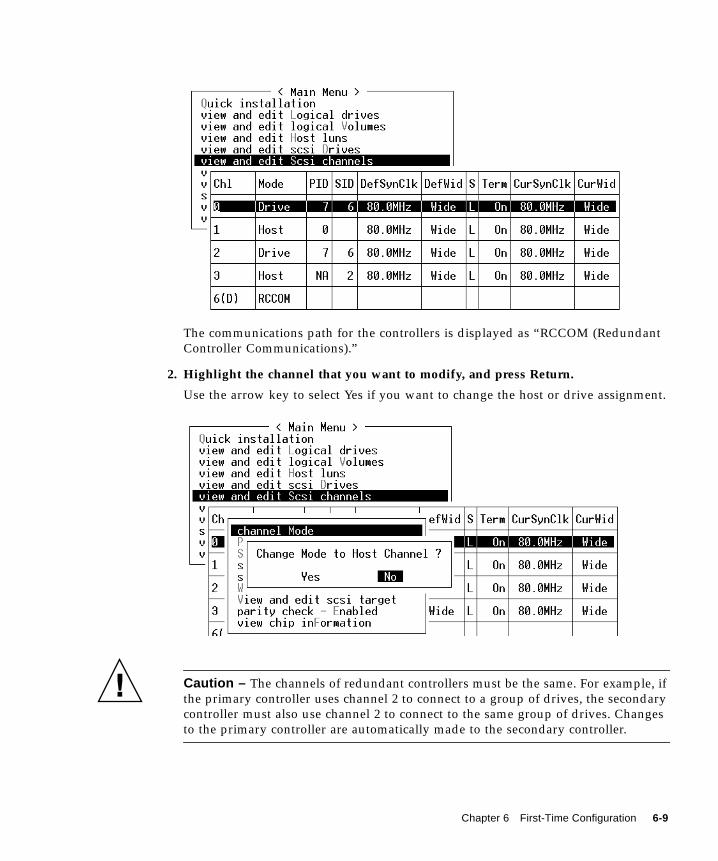
The communications path for the controllers is displayed as “RCCOM (RedundantController Communications).”
2. Highlight the channel that you want to modify, and press Return.
Use the arrow key to select Yes if you want to change the host or drive assignment.
Caution – The channels of redundant controllers must be the same. For example, ifthe primary controller uses channel 2 to connect to a group of drives, the secondarycontroller must also use channel 2 to connect to the same group of drives. Changesto the primary controller are automatically made to the secondary controller.
Chapter 6 First-Time Configuration 6-9
6.4.4 Creating Additional Host IDs (Optional)All RAID arrays are preconfigured when they arrive from the factory.
Default host channel IDs are:■ Channel 1 ID 0 (primary controller)■ Channel 3 ID 1 (secondary controller)
Each host channel might have two editable ID numbers:■ Primary controller ID■ Secondary controller ID
Each ID number must be a unique number within the host channel. You can:
■ Edit each host ID number to change the SCSI target number of each controllerhost channel that is seen by the host.
■ Add additional host ID numbers (by adding a second host ID to channels 1 and 3,and additional host IDs if you make Channel 2 into a host channel).
Note – To map 128 partitions into 128 LUNs, you must add additional host IDs. Aminimum of four host IDs are required; a maximum of six host IDs are possible. Fordetails on mapping 128 LUNs, refer to “Planning for 128 LUNs (Optional)” onpage 6-26.
To select a unique ID number for a host channel:
1. Select “view and edit Scsi channels.”
Press Return.
2. Highlight the host channel on which you want to edit the Primary/Secondary ID,and press Return.
Press Return to access the list of IDs and use the arrow keys to select an ID number(0 through 15), then press Return again.
3. Select “view and edit scsi Id” and press Return.
4. Select “Add Channel SCSI ID.”
5. Select the controller on which you want to add a host ID.
6-10 Sun StorEdge™ 3310 SCSI Array Installation, Operation, and Service Manual • October 2002
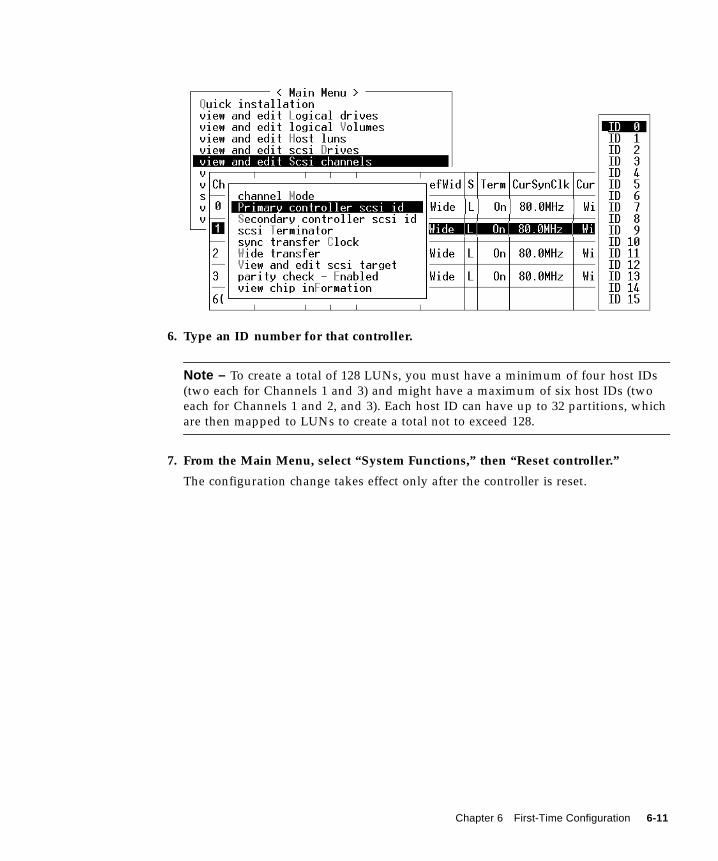
6. Type an ID number for that controller.
Note – To create a total of 128 LUNs, you must have a minimum of four host IDs(two each for Channels 1 and 3) and might have a maximum of six host IDs (twoeach for Channels 1 and 2, and 3). Each host ID can have up to 32 partitions, whichare then mapped to LUNs to create a total not to exceed 128.
7. From the Main Menu, select “System Functions,” then “Reset controller.”
The configuration change takes effect only after the controller is reset.
Chapter 6 First-Time Configuration 6-11
6.4.5 Enabling a Solaris Host to Recognize NewDevices and LUNsYou need to edit the sd.conf and /etc/system files for additional host LUNassignments. By default, a Solaris host is configured for one host LUN per SCSItarget which is not enough LUNs for a Sun StorEdge 3310 SCSI array.
1. Edit the /kernel/drv/sd.conf file to add more targets and LUNs (up to 32LUNs per logical drive, and a maximum of 128 LUNs per Sun StorEdge 3310array). See the example file“Solaris sd.conf Setup and Volume Labels” onpage E-1.
2. Add the following line to the /etc/system file if you have more than 8 LUNs(any LUNs in addition to LUNs 0 through 7):
Note – Editing the /etc/system file is needed only for onboard host bus adapterconnections.
3. Reboot the host to implement the file changes.
Solaris 8 requires a reconfiguration reboot to create device files and implementsd.conf changes but you do not need a reconfiguration reboot for Solaris 9.
For Solaris 9, use the following commands to create device files after you haveedited sd.conf and/or the /etc/system file. No reboot is necessary with thiscommand:
set scsi_options=0x43ff8
reboot -- -r
update_drv -f sddevfsadm
6-12 Sun StorEdge™ 3310 SCSI Array Installation, Operation, and Service Manual • October 2002
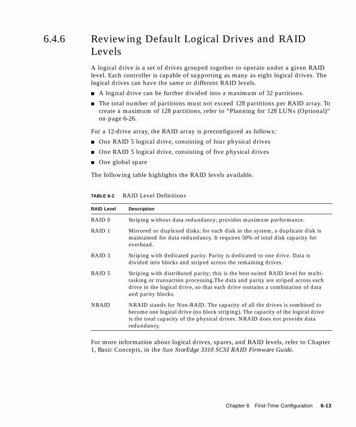
6.4.6 Reviewing Default Logical Drives and RAIDLevelsA logical drive is a set of drives grouped together to operate under a given RAIDlevel. Each controller is capable of supporting as many as eight logical drives. Thelogical drives can have the same or different RAID levels.
■ A logical drive can be further divided into a maximum of 32 partitions.
■ The total number of partitions must not exceed 128 partitions per RAID array. Tocreate a maximum of 128 partitions, refer to “Planning for 128 LUNs (Optional)”on page 6-26.
For a 12-drive array, the RAID array is preconfigured as follows:
■ One RAID 5 logical drive, consisting of four physical drives
■ One RAID 5 logical drive, consisting of five physical drives
■ One global spare
The following table highlights the RAID levels available.
For more information about logical drives, spares, and RAID levels, refer to Chapter1, Basic Concepts, in the Sun StorEdge 3310 SCSI RAID Firmware Guide.
TABLE 6-2 RAID Level Definitions
RAID Level Description
RAID 0 Striping without data redundancy; provides maximum performance.
RAID 1 Mirrored or duplexed disks; for each disk in the system, a duplicate disk ismaintained for data redundancy. It requires 50% of total disk capacity foroverhead.
RAID 3 Striping with dedicated parity. Parity is dedicated to one drive. Data isdivided into blocks and striped across the remaining drives.
RAID 5 Striping with distributed parity; this is the best-suited RAID level for multi-tasking or transaction processing.The data and parity are striped across eachdrive in the logical drive, so that each drive contains a combination of dataand parity blocks.
NRAID NRAID stands for Non-RAID. The capacity of all the drives is combined tobecome one logical drive (no block striping). The capacity of the logical driveis the total capacity of the physical drives. NRAID does not provide dataredundancy.
Chapter 6 First-Time Configuration 6-13
6.4.7 Completing Basic Configuration■ Optionally define any additional partitions for each logical drive. Refer to
“Partitioning a Logical Drive (optional)” on page 6-22.
■ Optionally add host SCSI IDs and more logical drives to create 128 LUNs.Refer to:
■ “Planning for 128 LUNs (Optional)” on page 6-26,■ “Creating Additional Host IDs (Optional)” on page 6-10,■ “Creating Logical Drive(s) (optional)” on page 6-14.
■ Map the logical drive(s) to the host LUNs (required). Refer to“Mapping LogicalDrive Partitions to Host LUNs” on page 6-27.
6.4.8 Creating Logical Drive(s) (optional)The RAID array is already configured with one or two RAID 5 logical drives and oneglobal spare. Each logical drive consists of a single partition by default.
This procedure is used to modify the RAID level and to add more logical drives, ifnecessary. In this procedure, you configure a logical drive to contain one or morehard drives based on the desired RAID level, and partition the logical drive intoadditional partitions.
Note – If you want to assign 128 partitions to 128 LUNs in an array, you need tohave a minimum of four logical drives (each with 32 partitions).
For redundancy across separate channels, you can also create a logical drivecontaining drives distributed over separate channels. You can then partition thelogical unit into one or several partitions.
A logical drive consists of a group of SCSI drives. Each logical drive can beconfigured a different RAID level.
A drive can be assigned as the local spare drive to one specified logical drive, or as aglobal spare drive that is available to all logical drives on the RAID array. Spares canbe part of automatic array rebuild. A spare is not available for logical drives with nodata redundancy (NRAID and RAID 0).
6-14 Sun StorEdge™ 3310 SCSI Array Installation, Operation, and Service Manual • October 2002
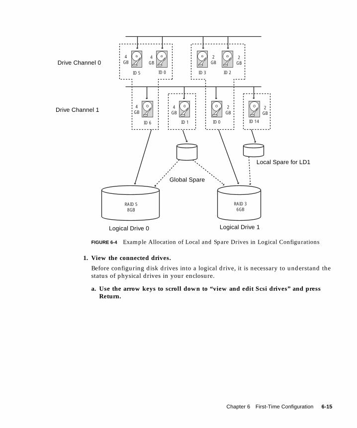
FIGURE 6-4 Example Allocation of Local and Spare Drives in Logical Configurations
1. View the connected drives.
Before configuring disk drives into a logical drive, it is necessary to understand thestatus of physical drives in your enclosure.
a. Use the arrow keys to scroll down to “view and edit Scsi drives” and pressReturn.
4GB
4GB
2GB
2GB
4GB
4GB
2GB
2GB
ID 5 ID 0 ID 3 ID 2
ID 6 ID 1 ID 0 ID 14
RAID 58GB
RAID 36GB
Drive Channel 0
Logical Drive 1
Global Spare
Local Spare for LD1
Logical Drive 0
Drive Channel 1
Chapter 6 First-Time Configuration 6-15
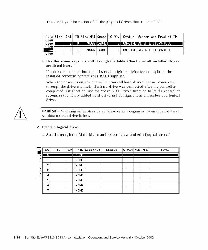
This displays information of all the physical drives that are installed.
b. Use the arrow keys to scroll through the table. Check that all installed drivesare listed here.
If a drive is installed but is not listed, it might be defective or might not beinstalled correctly, contact your RAID supplier.
When the power is on, the controller scans all hard drives that are connectedthrough the drive channels. If a hard drive was connected after the controllercompleted initialization, use the “Scan SCSI Drive” function to let the controllerrecognize the newly added hard drive and configure it as a member of a logicaldrive.
Caution – Scanning an existing drive removes its assignment to any logical drive.All data on that drive is lost.
2. Create a logical drive.
a. Scroll through the Main Menu and select “view and edit Logical drive.”
6-16 Sun StorEdge™ 3310 SCSI Array Installation, Operation, and Service Manual • October 2002
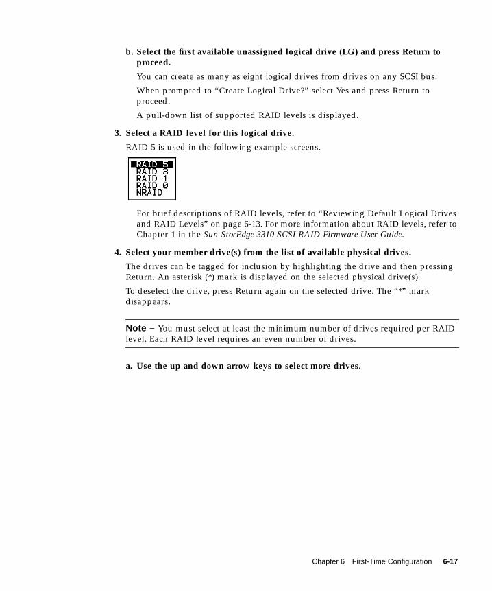
b. Select the first available unassigned logical drive (LG) and press Return toproceed.
You can create as many as eight logical drives from drives on any SCSI bus.
When prompted to “Create Logical Drive?” select Yes and press Return toproceed.
A pull-down list of supported RAID levels is displayed.
3. Select a RAID level for this logical drive.
RAID 5 is used in the following example screens.
For brief descriptions of RAID levels, refer to “Reviewing Default Logical Drivesand RAID Levels” on page 6-13. For more information about RAID levels, refer toChapter 1 in the Sun StorEdge 3310 SCSI RAID Firmware User Guide.
4. Select your member drive(s) from the list of available physical drives.
The drives can be tagged for inclusion by highlighting the drive and then pressingReturn. An asterisk (*) mark is displayed on the selected physical drive(s).
To deselect the drive, press Return again on the selected drive. The “*” markdisappears.
Note – You must select at least the minimum number of drives required per RAIDlevel. Each RAID level requires an even number of drives.
a. Use the up and down arrow keys to select more drives.
Chapter 6 First-Time Configuration 6-17
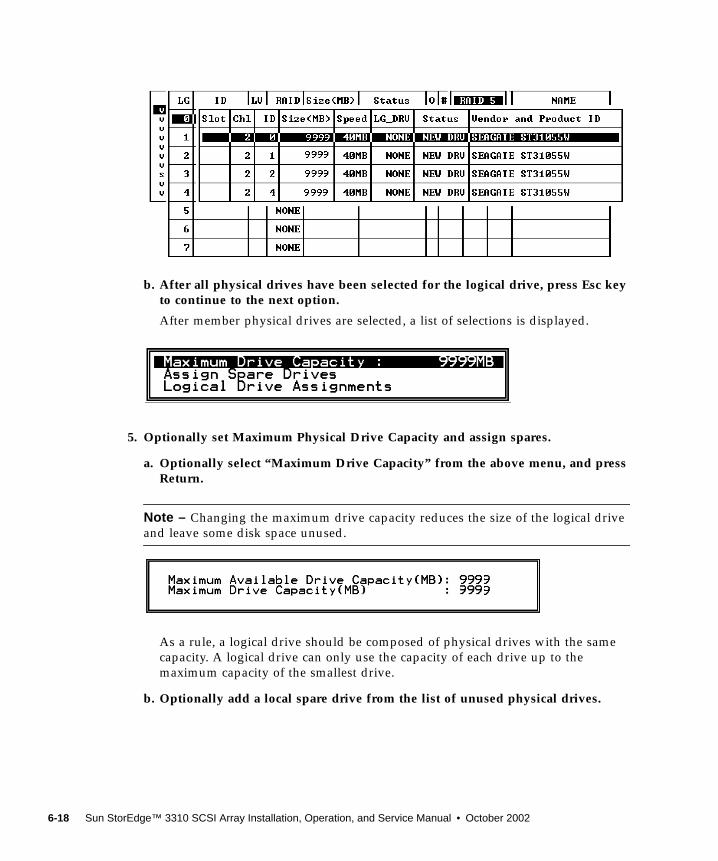
b. After all physical drives have been selected for the logical drive, press Esc keyto continue to the next option.
After member physical drives are selected, a list of selections is displayed.
5. Optionally set Maximum Physical Drive Capacity and assign spares.
a. Optionally select “Maximum Drive Capacity” from the above menu, and pressReturn.
Note – Changing the maximum drive capacity reduces the size of the logical driveand leave some disk space unused.
As a rule, a logical drive should be composed of physical drives with the samecapacity. A logical drive can only use the capacity of each drive up to themaximum capacity of the smallest drive.
b. Optionally add a local spare drive from the list of unused physical drives.
6-18 Sun StorEdge™ 3310 SCSI Array Installation, Operation, and Service Manual • October 2002
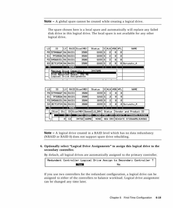
Note – A global spare cannot be created while creating a logical drive.
The spare chosen here is a local spare and automatically will replace any faileddisk drive in this logical drive. The local spare is not available for any otherlogical drive.
Note – A logical drive created in a RAID level which has no data redundancy(NRAID or RAID 0) does not support spare drive rebuilding.
6. Optionally select “Logical Drive Assignments” to assign this logical drive to thesecondary controller.
By default, all logical drives are automatically assigned to the primary controller.
If you use two controllers for the redundant configuration, a logical drive can beassigned to either of the controllers to balance workload. Logical drive assignmentcan be changed any time later.
Chapter 6 First-Time Configuration 6-19
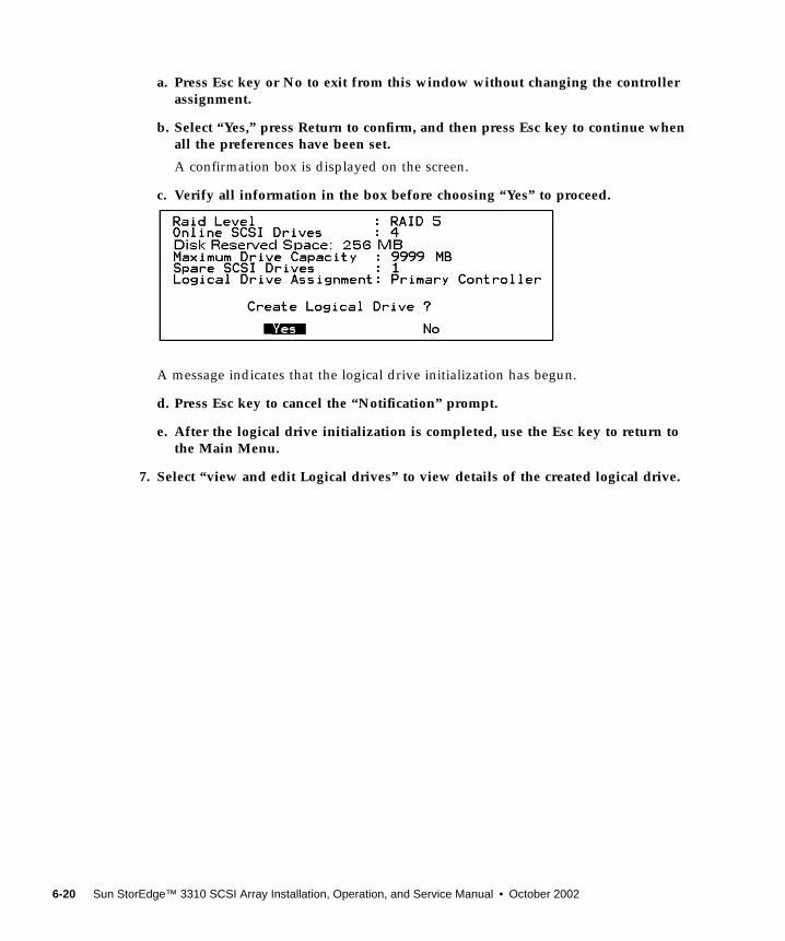
a. Press Esc key or No to exit from this window without changing the controllerassignment.
b. Select “Yes,” press Return to confirm, and then press Esc key to continue whenall the preferences have been set.
A confirmation box is displayed on the screen.
c. Verify all information in the box before choosing “Yes” to proceed.
A message indicates that the logical drive initialization has begun.
d. Press Esc key to cancel the “Notification” prompt.
e. After the logical drive initialization is completed, use the Esc key to return tothe Main Menu.
7. Select “view and edit Logical drives” to view details of the created logical drive.
6-20 Sun StorEdge™ 3310 SCSI Array Installation, Operation, and Service Manual • October 2002
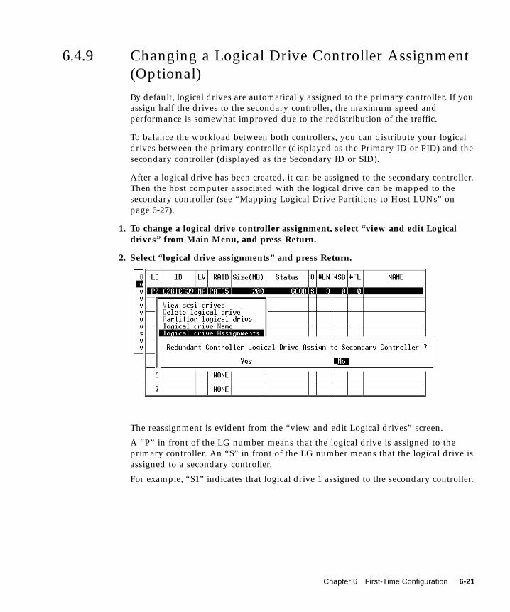
6.4.9 Changing a Logical Drive Controller Assignment(Optional)By default, logical drives are automatically assigned to the primary controller. If youassign half the drives to the secondary controller, the maximum speed andperformance is somewhat improved due to the redistribution of the traffic.
To balance the workload between both controllers, you can distribute your logicaldrives between the primary controller (displayed as the Primary ID or PID) and thesecondary controller (displayed as the Secondary ID or SID).
After a logical drive has been created, it can be assigned to the secondary controller.Then the host computer associated with the logical drive can be mapped to thesecondary controller (see “Mapping Logical Drive Partitions to Host LUNs” onpage 6-27).
1. To change a logical drive controller assignment, select “view and edit Logicaldrives” from Main Menu, and press Return.
2. Select “logical drive assignments” and press Return.
The reassignment is evident from the “view and edit Logical drives” screen.
A “P” in front of the LG number means that the logical drive is assigned to theprimary controller. An “S” in front of the LG number means that the logical drive isassigned to a secondary controller.
For example, “S1” indicates that logical drive 1 assigned to the secondary controller.
Chapter 6 First-Time Configuration 6-21
Note – The editable logical drive NAME name is used only in the RAID firmwareadministration and monitoring, and does not appear anywhere on the host. You cancreate a logical drive NAME after the logical drive is created: Select the logical drivein the above screen, and press Return. Then select “logical drive name,” type thedesired name, and press Return.
3. Press Esc to return to the Main Menu.
4. Reset the controller to implement the change.
Select “system Functions” on the Main Menu. Then select “Reset controller” andpress Return.
You must reset the controller for the changes to take effect.
6.4.10 Partitioning a Logical Drive (optional)You might divide a logical drive into several partitions, or use the entire logicaldrive as a single partition. You might configure up to 32 partitions for each logicaldrive.
For guidelines on setting up 128 LUNs, refer to “Planning for 128 LUNs (Optional)”on page 6-26.
Caution – If you modify the size of a partition or logical drive, you lose all data onthose drives.
6-22 Sun StorEdge™ 3310 SCSI Array Installation, Operation, and Service Manual • October 2002
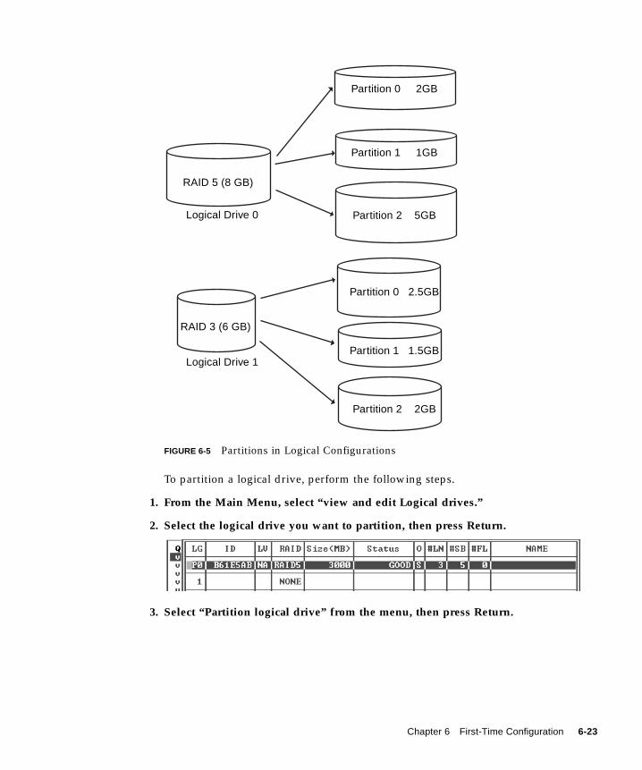
FIGURE 6-5 Partitions in Logical Configurations
To partition a logical drive, perform the following steps.
1. From the Main Menu, select “view and edit Logical drives.”
2. Select the logical drive you want to partition, then press Return.
3. Select “Partition logical drive” from the menu, then press Return.
RAID 5 (8 GB)
RAID 3 (6 GB)
Partition 0 2GB
Partition 1 1GB
Partition 2 5GB
Partition 0 2.5GB
Partition 2 2GB
Logical Drive 0
Logical Drive 1Partition 1 1.5GB
Chapter 6 First-Time Configuration 6-23
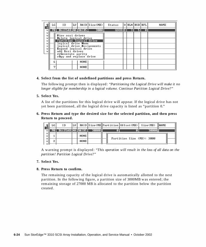
4. Select from the list of undefined partitions and press Return.
The following prompt then is displayed: “Partitioning the Logical Drive will make it nolonger eligible for membership in a logical volume. Continue Partition Logical Drive?”
5. Select Yes.
A list of the partitions for this logical drive will appear. If the logical drive has notyet been partitioned, all the logical drive capacity is listed as “partition 0.”
6. Press Return and type the desired size for the selected partition, and then pressReturn to proceed.
A warning prompt is displayed: “This operation will result in the loss of all data on thepartition! Partition Logical Drive?”
7. Select Yes.
8. Press Return to confirm.
The remaining capacity of the logical drive is automatically allotted to the nextpartition. In the following figure, a partition size of 3000MB was entered; theremaining storage of 27000 MB is allocated to the partition below the partitioncreated.
6-24 Sun StorEdge™ 3310 SCSI Array Installation, Operation, and Service Manual • October 2002
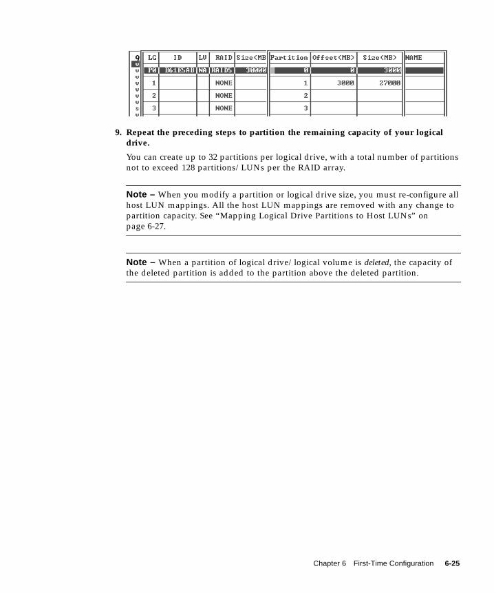
9. Repeat the preceding steps to partition the remaining capacity of your logicaldrive.
You can create up to 32 partitions per logical drive, with a total number of partitionsnot to exceed 128 partitions/LUNs per the RAID array.
Note – When you modify a partition or logical drive size, you must re-configure allhost LUN mappings. All the host LUN mappings are removed with any change topartition capacity. See “Mapping Logical Drive Partitions to Host LUNs” onpage 6-27.
Note – When a partition of logical drive/logical volume is deleted, the capacity ofthe deleted partition is added to the partition above the deleted partition.
Chapter 6 First-Time Configuration 6-25
6.4.11 Planning for 128 LUNs (Optional)If you want to create 128 LUNs which is the maximum number of storage partitionswhich can be mapped for a RAID array, set up one of the following configurations:
■ Create four host IDs. Create four logical drives. Partition each logical drive into 32partitions (4 times 32 = 128). Map the 128 partitions to the four host IDs. This isthe most commonly used configuration.
or
■ Create six host IDs (this requires three host drives), perform one of the followingsteps, and then map the 128 partitions to the 6 host IDs.
■ Create 4 logical drives of 32 partitions each
■ Create 5 logical drives with total number of partitions equaling 128 (fourlogical drives with 25 partitions each and one with 28 partitions)
■ Create 6 logical drives (six logical drives with 21 partitions each and one with23 partitions).
For details on how to add host IDs, refer to “Creating Additional Host IDs(Optional)” on page 6-10.
Note – For an overview of how partitions, LUNs, and host IDs work, refer to“Mapping Logical Drive Partitions to Host LUNs” on page 6-27.
To set up 128 LUNs, the following steps are required.
1. Create a minimum of four host IDs.
By default, you have two host IDs: Channel 1 ID 0 (primary controller) and Channel3 ID 1 (secondary controller). You can have a total of two IDs per channel, one forthe Primary Controller and one for the secondary controller.
For the detailed procedure, refer to “Creating Additional Host IDs (Optional)” onpage 6-10.
2. Confirm that the allowed number of LUNs per host id is 32.
Go to “view and edit Configuration parameters,” and select “hostside SCSIParameters.”
If the “LUNs per Host SCSI ID” is not 32, highlight the line, press Return and selectthe number 32.
6-26 Sun StorEdge™ 3310 SCSI Array Installation, Operation, and Service Manual • October 2002
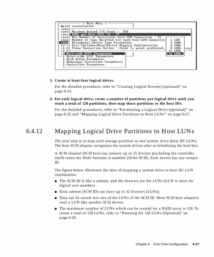
3. Create at least four logical drives.
For the detailed procedure, refer to “Creating Logical Drive(s) (optional)” onpage 6-14.
4. For each logical drive, create a number of partitions per logical drive until youreach a total of 128 partitions, then map those partitions to the host IDs.
For the detailed procedures, refer to “Partitioning a Logical Drive (optional)” onpage 6-22 and “Mapping Logical Drive Partitions to Host LUNs” on page 6-27.
6.4.12 Mapping Logical Drive Partitions to Host LUNsThe next step is to map each storage partition as one system drive (host ID/LUN).The host SCSI adapter recognizes the system drives after re-initializing the host bus.
A SCSI channel (SCSI bus) can connect up to 15 devices (excluding the controlleritself) when the Wide function is enabled (16-bit SCSI). Each device has one uniqueID.
The figure below illustrates the idea of mapping a system drive to host ID/LUNcombination.
■ The SCSI ID is like a cabinet, and the drawers are the LUNs (LUN is short forlogical unit number).
■ Each cabinet (SCSI ID) can have up to 32 drawers (LUNs).
■ Data can be stored into one of the LUNs of the SCSI ID. Most SCSI host adapterstreat a LUN like another SCSI device.
■ The maximum number of LUNs which can be created for a RAID array is 128. Tocreate a total of 128 LUNs, refer to “Planning for 128 LUNs (Optional)” onpage 6-26.
Chapter 6 First-Time Configuration 6-27
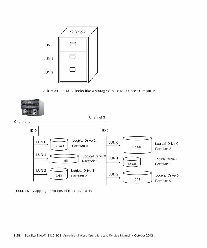
Each SCSI ID/LUN looks like a storage device to the host computer.
FIGURE 6-6 Mapping Partitions to Host ID/LUNs
LUN 1
LUN 2
LUN 0
ID 0 ID 1
2.5GB
1GB
2GB2GB
1.5GB
5GB
Logical Drive 1
Logical Drive 0
Logical Drive 1
Logical Drive 0
Logical Drive 0
LUN 0
LUN 1
LUN 2
LUN 0
LUN 1
LUN 2
Logical Drive 1
ID 0 ID 1
Channel 3Channel 1
Partition 1
Partition 2
Partition 0
Partition 0
Partition 1
Partition 2
6-28 Sun StorEdge™ 3310 SCSI Array Installation, Operation, and Service Manual • October 2002
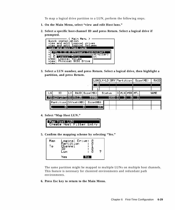
To map a logical drive partition to a LUN, perform the following steps.
1. On the Main Menu, select “view and edit Host luns.”
2. Select a specific host-channel ID and press Return. Select a logical drive ifprompted.
3. Select a LUN number, and press Return. Select a logical drive, then highlight apartition, and press Return.
4. Select “Map Host LUN.”
5. Confirm the mapping scheme by selecting “Yes.”
The same partition might be mapped to multiple LUNs on multiple host channels.This feature is necessary for clustered environments and redundant pathenvironments.
6. Press Esc key to return to the Main Menu.
Chapter 6 First-Time Configuration 6-29

7. Repeat the above procedure for each partition until all partitions are mapped to aLUN.
8. Select “system Functions” on the Main Menu, and select “Reset controller” toimplement the new configuration settings.
9. To verify unique mapping of each LUN (unique LUN number, unique DRVnumber, or unique Partition number), select the “view and edit Host luns”command and press Return.
6.4.13 Create Device Files for Solaris Environment1. Edit the /kernel/drv/sd.conf file to include the newly mapped LUNs which
are available to the host. For details, refer to “Solaris sd.conf Setup and VolumeLabels” on page E-1.
2. For Solaris 8 and higher, to create device files for the newly mapped LUNs on thehost, type:
3. The new LUNs are displayed when you use the Solaris format command.
4. If the format command does not see the newly mapped LUNs, re-check thesd.conf file for accuracy and reboot the host:
/usr/sbin/devfsadm -v
format
reboot -- -r
6-30 Sun StorEdge™ 3310 SCSI Array Installation, Operation, and Service Manual • October 2002
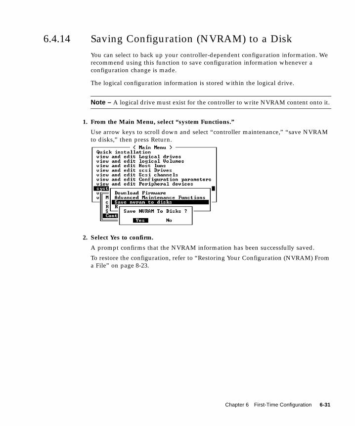
6.4.14 Saving Configuration (NVRAM) to a DiskYou can select to back up your controller-dependent configuration information. Werecommend using this function to save configuration information whenever aconfiguration change is made.
The logical configuration information is stored within the logical drive.
Note – A logical drive must exist for the controller to write NVRAM content onto it.
1. From the Main Menu, select “system Functions.”
Use arrow keys to scroll down and select “controller maintenance,” “save NVRAMto disks,” then press Return.
2. Select Yes to confirm.
A prompt confirms that the NVRAM information has been successfully saved.
To restore the configuration, refer to “Restoring Your Configuration (NVRAM) Froma File” on page 8-23.
Chapter 6 First-Time Configuration 6-31
6.5 Installing SoftwareThe following software tools are available on the Sun StorEdge Professional StorageManager CD-ROM, provided with your array:
■ Sun StorEdge 3310 SCSI Configuration Service, a management and monitoringprogram
■ Sun StorEdge 3310 SCSI Diagnostic Reporter software, a monitoring utility
■ Sun StorEdge 3310 SCSI CLI, a command line utility to download firmware anddisplay the event log
The Sun StorEdge 3310 SCSI Array Documentation CD-ROM provides the related userguides with detailed installation and configuration procedures for these tools.
6.5.1 Other Supported SoftwareFor other supported software, see the Sun StorEdge 3310 SCSI Array Release Notes.
6.5.2 Enabling VERITAS DMPTo enable VERITAS Dynamic Multi-Pathing (DMP) support on VERITAS VolumeManager Version 3.2, perform the following steps.
1. Configure at least two SCSI channels as host channels (channels 1 and 3 bydefault) and add additional SCSI host IDs if needed.
2. Connect host cables to the I/O host ports in step 1.
3. Map each LUN to two host channels to provide dual-pathed LUNs.
4. Add the correct SCSI string to vxddladm so VxVM can manage the LUNs as amulti-pathed JBOD.
5. Reboot the hosts. System reboot is required to implement these changes.
# vxddladm addjbod vid=SUN pid="StorEdge 3310"# vxddladm listjbodVID PID Opcode Page Code Page Offset SNO length================================================================SEAGATE ALL PIDs 18 -1 36 12SUN StorEdge 3310 18 -1 36 12
6-32 Sun StorEdge™ 3310 SCSI Array Installation, Operation, and Service Manual • October 2002
CHAPTER 7
Checking LEDs
This chapter describes the front- and rear-panel LEDs, which give the clear status ofthe operation of all drives and modules. Topics covered in this chapter are:
■ “LEDs When Array Is First Powered On” on page 7-1■ “Front-Panel LEDs” on page 7-3■ “Rear-Panel LEDs” on page 7-5
■ “RAID Controller LEDs” on page 7-5■ “Other Rear-Panel LEDs” on page 7-7
7.1 LEDs When Array Is First Powered OnWith the array powered up without the SCSI bus configuration cable installed whilethe array is not connected to a server, you should see the LED conditions describedin TABLE 7-1 and TABLE 7-2.
TABLE 7-1 Front-Panel LED Status When Array Is First Powered On
Drive LEDs Solid green
Chassis ear LEDs Solid green
7-1
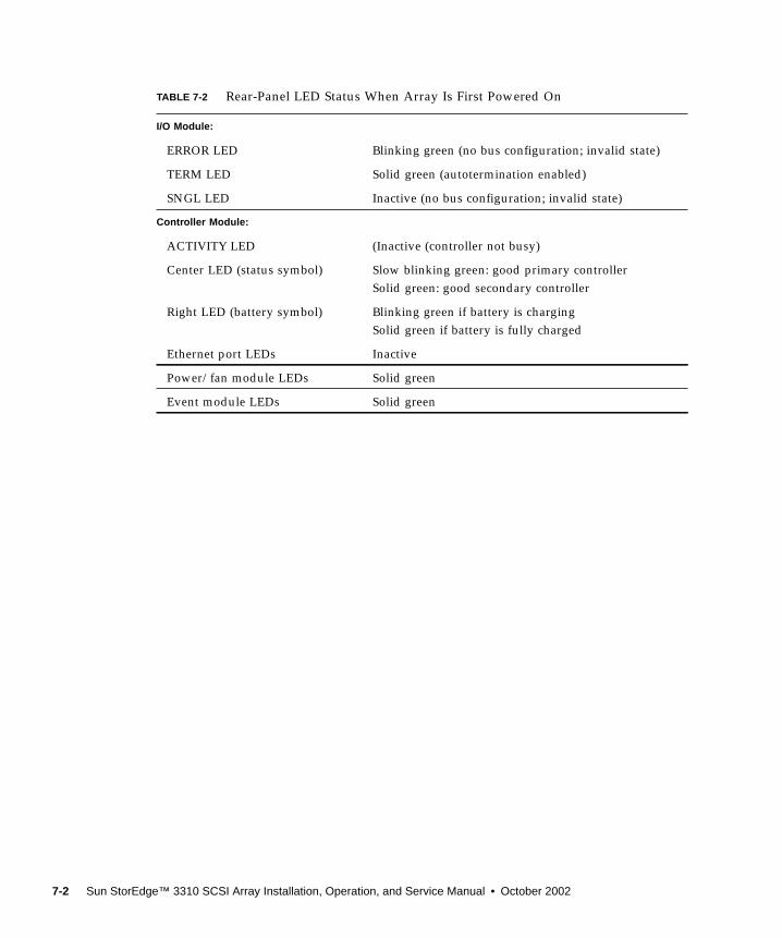
TABLE 7-2 Rear-Panel LED Status When Array Is First Powered On
I/O Module:
ERROR LED Blinking green (no bus configuration; invalid state)
TERM LED Solid green (autotermination enabled)
SNGL LED Inactive (no bus configuration; invalid state)
Controller Module:
ACTIVITY LED (Inactive (controller not busy)
Center LED (status symbol) Slow blinking green: good primary controllerSolid green: good secondary controller
Right LED (battery symbol) Blinking green if battery is chargingSolid green if battery is fully charged
Ethernet port LEDs Inactive
Power/fan module LEDs Solid green
Event module LEDs Solid green
7-2 Sun StorEdge™ 3310 SCSI Array Installation, Operation, and Service Manual • October 2002
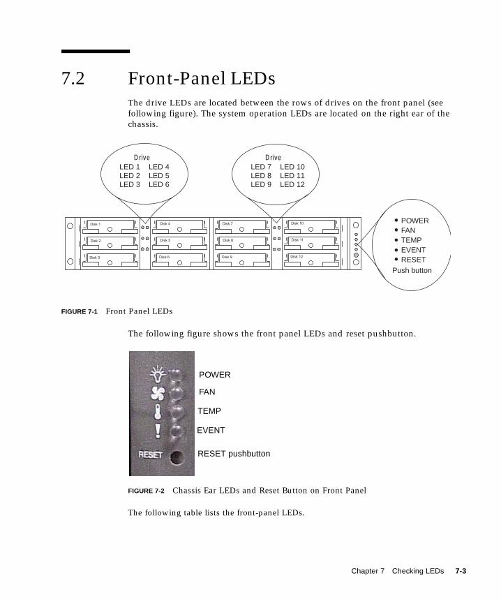
7.2 Front-Panel LEDsThe drive LEDs are located between the rows of drives on the front panel (seefollowing figure). The system operation LEDs are located on the right ear of thechassis.
FIGURE 7-1 Front Panel LEDs
The following figure shows the front panel LEDs and reset pushbutton.
FIGURE 7-2 Chassis Ear LEDs and Reset Button on Front Panel
The following table lists the front-panel LEDs.
Disk 1
Disk 2
Disk 3
Disk 4
Disk 5
Disk 6
Disk 7
Disk 8
Disk 9
Disk 10
Disk 11
Disk 12
DriveLED 1LED 2LED 3
LED 4LED 5LED 6
DriveLED 7LED 8LED 9
LED 10LED 11LED 12
POWERFANTEMPEVENTRESET
Push button
POWER
FAN
TEMP
EVENT
RESET pushbutton
Chapter 7 Checking LEDs 7-3
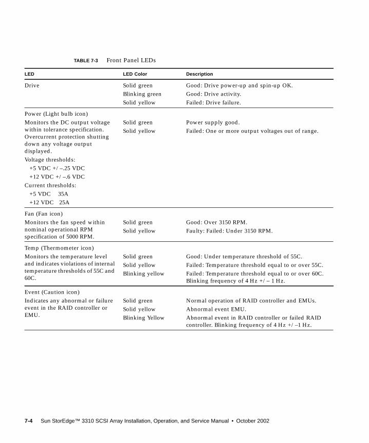
TABLE 7-3 Front Panel LEDs
LED LED Color Description
Drive Solid greenBlinking greenSolid yellow
Good: Drive power-up and spin-up OK.Good: Drive activity.Failed: Drive failure.
Power (Light bulb icon)Monitors the DC output voltagewithin tolerance specification.Overcurrent protection shuttingdown any voltage outputdisplayed.Voltage thresholds:
+5 VDC +/–.25 VDC+12 VDC +/–.6 VDC
Current thresholds:+5 VDC 35A+12 VDC 25A
Solid greenSolid yellow
Power supply good.Failed: One or more output voltages out of range.
Fan (Fan icon)Monitors the fan speed withinnominal operational RPMspecification of 5000 RPM.
Solid greenSolid yellow
Good: Over 3150 RPM.Faulty: Failed: Under 3150 RPM.
Temp (Thermometer icon)Monitors the temperature leveland indicates violations of internaltemperature thresholds of 55C and60C.
Solid greenSolid yellowBlinking yellow
Good: Under temperature threshold of 55C.Failed: Temperature threshold equal to or over 55C.Failed: Temperature threshold equal to or over 60C.Blinking frequency of 4 Hz +/– 1 Hz.
Event (Caution icon)Indicates any abnormal or failureevent in the RAID controller orEMU.
Solid greenSolid yellowBlinking Yellow
Normal operation of RAID controller and EMUs.Abnormal event EMU.Abnormal event in RAID controller or failed RAIDcontroller. Blinking frequency of 4 Hz +/–1 Hz.
7-4 Sun StorEdge™ 3310 SCSI Array Installation, Operation, and Service Manual • October 2002
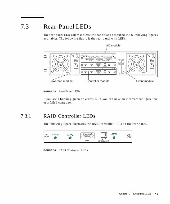
7.3 Rear-Panel LEDsThe rear-panel LED colors indicate the conditions described in the following figuresand tables. The following figure is the rear-panel with LEDs.
FIGURE 7-3 Rear-Panel LEDs
If you see a blinking green or yellow LED, you can have an incorrect configurationor a failed component.
7.3.1 RAID Controller LEDsThe following figure illustrates the RAID controller LEDs on the rear panel.
FIGURE 7-4 RAID Controller LEDs
POWER
COM 10/100 BASE-T
ERROR TERM
SNGLCH 0
CH 1
CH 3
CH 2
SNGL BUS CONF
DUAL BUS CONF
TERM
DB
SB SB
EVENT 1
EVENT 2
POWER
Activity
< >...+
COM 10/100 BASE-T
Activity
< >...+
PS PS
EMUEMU
I/O module
Power/fan module Controller module Event module
COM 10/100 BASE-T
Activity
< >...+
Chapter 7 Checking LEDs 7-5
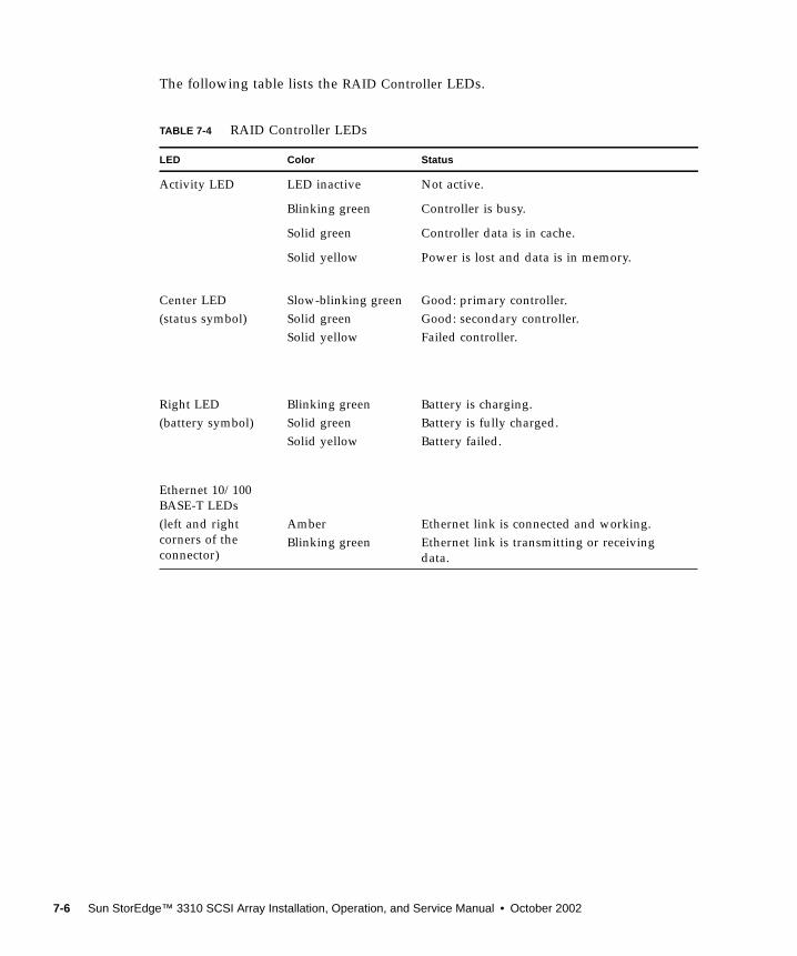
The following table lists the RAID Controller LEDs.
TABLE 7-4 RAID Controller LEDs
LED Color Status
Activity LED LED inactive Not active.
Blinking green Controller is busy.
Solid green Controller data is in cache.
Solid yellow Power is lost and data is in memory.
Center LED(status symbol)
Slow-blinking greenSolid greenSolid yellow
Good: primary controller.Good: secondary controller.Failed controller.
Right LED(battery symbol)
Blinking greenSolid greenSolid yellow
Battery is charging.Battery is fully charged.Battery failed.
Ethernet 10/100BASE-T LEDs(left and rightcorners of theconnector)
AmberBlinking green
Ethernet link is connected and working.Ethernet link is transmitting or receivingdata.
7-6 Sun StorEdge™ 3310 SCSI Array Installation, Operation, and Service Manual • October 2002
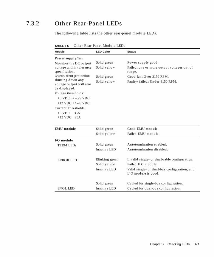
7.3.2 Other Rear-Panel LEDsThe following table lists the other rear-panel module LEDs.
TABLE 7-5 Other Rear-Panel Module LEDs
Module LED Color Status
Power supply/fanMonitors the DC outputvoltage within tolerancespecification.Overcurrent protectionshutting down anyvoltage output will alsobe displayed.Voltage thresholds:
+5 VDC +/–.25 VDC+12 VDC +/–.6 VDC
Current Thresholds:+5 VDC 35A+12 VDC 25A
Solid greenSolid yellow
Solid greenSolid yellow
Power supply good.Failed: one or more output voltages out ofrange.Good fan: Over 3150 RPM.Faulty/failed: Under 3150 RPM.
EMU module Solid greenSolid yellow
Good EMU module.Failed EMU module.
I/O moduleTERM LEDs
ERROR LED
SNGL LED
Solid greenInactive LED
Blinking greenSolid yellowInactive LED
Solid greenInactive LED
Autotermination enabled.Autotermination disabled.
Invalid single- or dual-cable configuration.Failed I/O module.Valid single- or dual-bus configuration, andI/O module is good.
Cabled for single-bus configuration.Cabled for dual-bus configuration.
Chapter 7 Checking LEDs 7-7
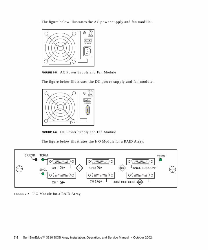
The figure below illustrates the AC power supply and fan module.
FIGURE 7-5 AC Power Supply and Fan Module
The figure below illustrates the DC power supply and fan module.
FIGURE 7-6 DC Power Supply and Fan Module
The figure below illustrates the I/O Module for a RAID Array.
FIGURE 7-7 I/O Module for a RAID Array
POWER
POWER
SNGLCH 0
CH 1
CH 3
CH 2
SNGL BUS CONF
DUAL BUS CONF DB
SB SB
ERROR TERM TERM
7-8 Sun StorEdge™ 3310 SCSI Array Installation, Operation, and Service Manual • October 2002
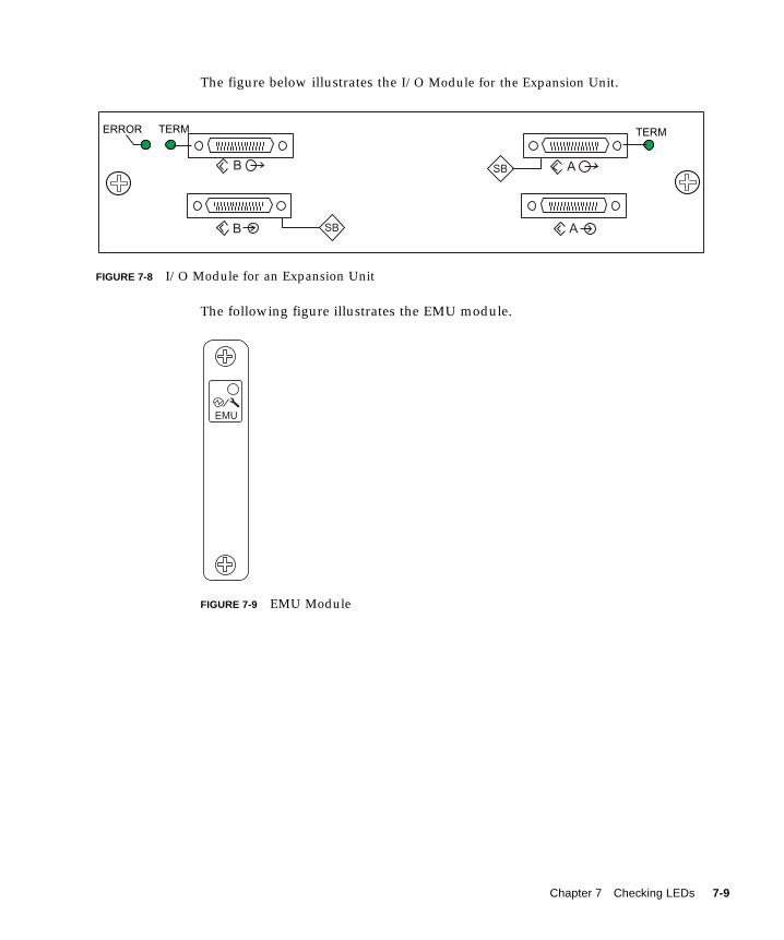
The figure below illustrates the I/O Module for the Expansion Unit.
FIGURE 7-8 I/O Module for an Expansion Unit
The following figure illustrates the EMU module.
FIGURE 7-9 EMU Module
AB
B
TERMERROR TERM
SB
SB A
EMU
Chapter 7 Checking LEDs 7-9

7-10 Sun StorEdge™ 3310 SCSI Array Installation, Operation, and Service Manual • October 2002
CHAPTER 8
Maintaining and TroubleshootingYour Array
This chapter covers the following maintenance and troubleshooting topics:
■ “Problem In Seeing the Array on the Host” on page 8-2■ “RAID LUNs Not Visible to the Host” on page 8-2■ “JBOD Disks Not Visible to the Host” on page 8-3
■ “Key Screens and Commands” on page 8-3■ “The Controller Firmware Initial Screen” on page 8-3■ “Main Menu” on page 8-4■ “Quick Installation” on page 8-5
■ “Checking Status Windows” on page 8-5■ “Logical Drive Status Table” on page 8-5■ “Logical Volume Status Table” on page 8-7■ “SCSI Drive Status Table” on page 8-8■ “SCSI Channel Status Table” on page 8-10■ “Controller Voltage Temperature Status” on page 8-12■ “Viewing SAF-TE Status” on page 8-13■ “Viewing Event Logs on the Screen” on page 8-15
■ “Controller Failure Symptoms, Logical Drive Rebuild, and Replacement” onpage 8-16■ “General Controller Failure Response” on page 8-16■ “Automatic Logical Drive Rebuild” on page 8-17■ “Manual Rebuild” on page 8-17■ “Concurrent Rebuild in RAID (0+1)” on page 8-20■ “Identifying a Failed Drive for Replacement” on page 8-20■ “Restoring Your Configuration (NVRAM) From a File” on page 8-23■ “Fatal Drive Failure” on page 8-24
■ “Upgrading Firmware” on page 8-25■ “Review Firmware Upgrade Features” on page 8-25■ “Downloading Firmware Upgrades” on page 8-26
8-1
To check front-panel and back-panel LEDs, see “Checking LEDs” on page 7-1.
For more troubleshooting tips, refer to the Sun StorEdge 3310 SCSI Release Notes at:
www.sun.com/products-n-solutions/hardware/docs/Network_Storage_Solutions/Workgroup/3310
8.1 Problem In Seeing the Array on the Host
8.1.1 RAID LUNs Not Visible to the HostBy default, all RAID arrays are preconfigured with one or two logical drives. For alogical drive to be visible to the host server, its partitions must be mapped to hostLUNs. (For mapping details, refer to “Mapping Logical Drive Partitions to HostLUNs” on page 6-27.) Check that you have completed this task.
To make the mapped LUNs visible to the host, perform the following steps for theSolaris host:
1. Ensure that the /kernel/drv/sd.conf file is correctly configured. See theexample file“Solaris sd.conf Setup and Volume Labels” on page E-1.
2. Add the following line to the /etc/system file if you have more than 8 LUNs(any LUNs in addition to LUNs 0 through 7). This is required for many onboardhost adapters.
3. Run the devfsadm utility to rescan the newly mapped LUNs.
4. To implement all changes to the above files, reboot the host with the reboot ---r command.
The new LUNs are displayed when you perform the format command.
set scsi_options=0x43ff8
8-2 Sun StorEdge™ 3310 SCSI Array Installation, Operation, and Service Manual • October 2002
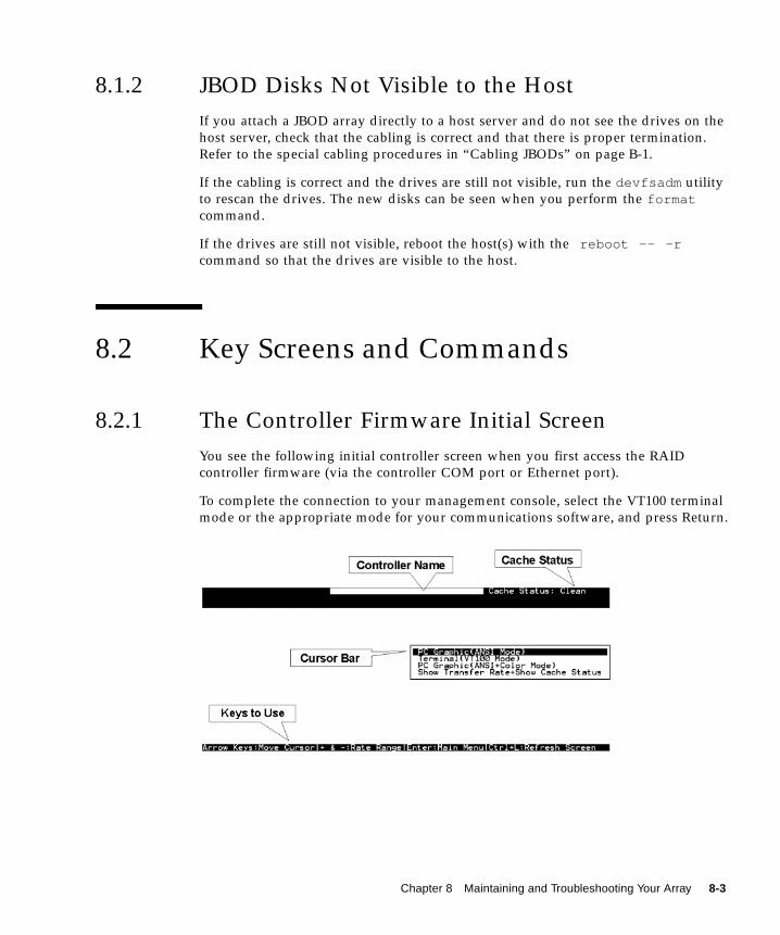
8.1.2 JBOD Disks Not Visible to the HostIf you attach a JBOD array directly to a host server and do not see the drives on thehost server, check that the cabling is correct and that there is proper termination.Refer to the special cabling procedures in “Cabling JBODs” on page B-1.
If the cabling is correct and the drives are still not visible, run the devfsadm utilityto rescan the drives. The new disks can be seen when you perform the formatcommand.
If the drives are still not visible, reboot the host(s) with the reboot -- -rcommand so that the drives are visible to the host.
8.2 Key Screens and Commands
8.2.1 The Controller Firmware Initial ScreenYou see the following initial controller screen when you first access the RAIDcontroller firmware (via the controller COM port or Ethernet port).
To complete the connection to your management console, select the VT100 terminalmode or the appropriate mode for your communications software, and press Return.
Chapter 8 Maintaining and Troubleshooting Your Array 8-3
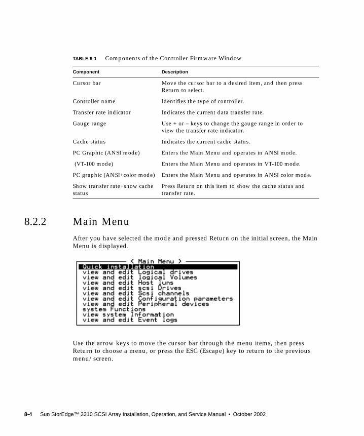
8.2.2 Main MenuAfter you have selected the mode and pressed Return on the initial screen, the MainMenu is displayed.
Use the arrow keys to move the cursor bar through the menu items, then pressReturn to choose a menu, or press the ESC (Escape) key to return to the previousmenu/screen.
TABLE 8-1 Components of the Controller Firmware Window
Component Description
Cursor bar Move the cursor bar to a desired item, and then pressReturn to select.
Controller name Identifies the type of controller.
Transfer rate indicator Indicates the current data transfer rate.
Gauge range Use + or – keys to change the gauge range in order toview the transfer rate indicator.
Cache status Indicates the current cache status.
PC Graphic (ANSI mode) Enters the Main Menu and operates in ANSI mode.
(VT-100 mode) Enters the Main Menu and operates in VT-100 mode.
PC graphic (ANSI+color mode) Enters the Main Menu and operates in ANSI color mode.
Show transfer rate+show cachestatus
Press Return on this item to show the cache status andtransfer rate.
8-4 Sun StorEdge™ 3310 SCSI Array Installation, Operation, and Service Manual • October 2002
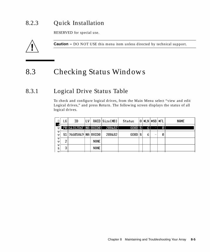
8.2.3 Quick InstallationRESERVED for special use.
Caution – DO NOT USE this menu item unless directed by technical support.
8.3 Checking Status Windows
8.3.1 Logical Drive Status TableTo check and configure logical drives, from the Main Menu select “view and editLogical drives,” and press Return. The following screen displays the status of alllogical drives.
Chapter 8 Maintaining and Troubleshooting Your Array 8-5
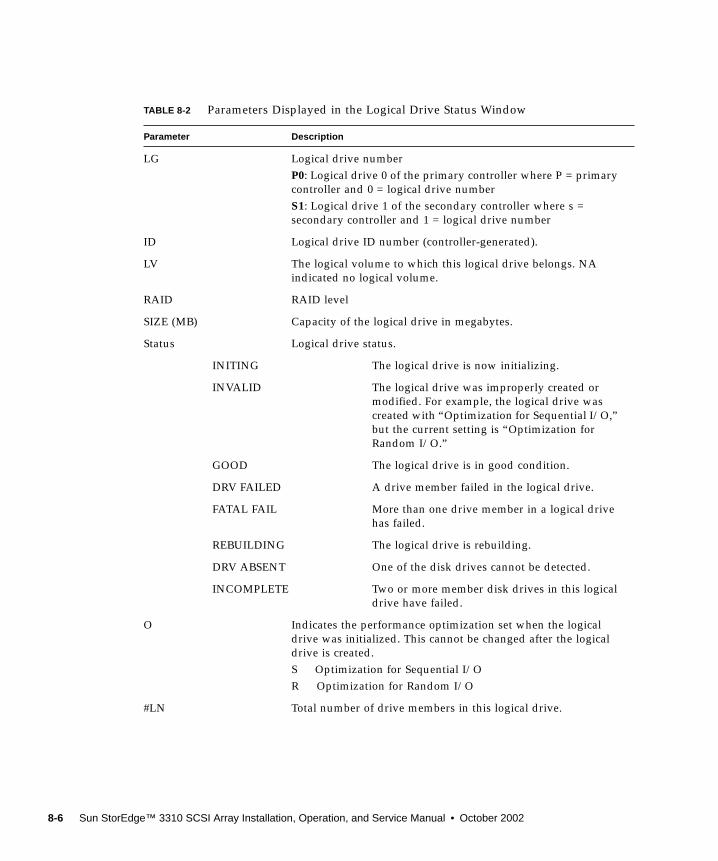
TABLE 8-2 Parameters Displayed in the Logical Drive Status Window
Parameter Description
LG Logical drive numberP0: Logical drive 0 of the primary controller where P = primarycontroller and 0 = logical drive numberS1: Logical drive 1 of the secondary controller where s =secondary controller and 1 = logical drive number
ID Logical drive ID number (controller-generated).
LV The logical volume to which this logical drive belongs. NAindicated no logical volume.
RAID RAID level
SIZE (MB) Capacity of the logical drive in megabytes.
Status Logical drive status.
INITING The logical drive is now initializing.
INVALID The logical drive was improperly created ormodified. For example, the logical drive wascreated with “Optimization for Sequential I/O,”but the current setting is “Optimization forRandom I/O.”
GOOD The logical drive is in good condition.
DRV FAILED A drive member failed in the logical drive.
FATAL FAIL More than one drive member in a logical drivehas failed.
REBUILDING The logical drive is rebuilding.
DRV ABSENT
INCOMPLETE
One of the disk drives cannot be detected.
Two or more member disk drives in this logicaldrive have failed.
O Indicates the performance optimization set when the logicaldrive was initialized. This cannot be changed after the logicaldrive is created.S Optimization for Sequential I/OR Optimization for Random I/O
#LN Total number of drive members in this logical drive.
8-6 Sun StorEdge™ 3310 SCSI Array Installation, Operation, and Service Manual • October 2002
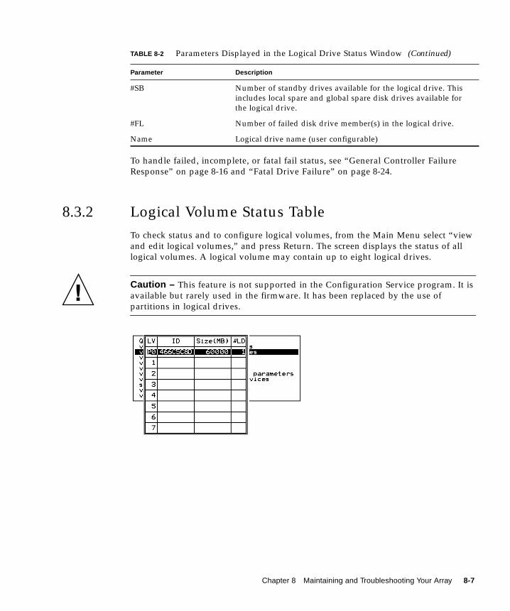
To handle failed, incomplete, or fatal fail status, see “General Controller FailureResponse” on page 8-16 and “Fatal Drive Failure” on page 8-24.
8.3.2 Logical Volume Status TableTo check status and to configure logical volumes, from the Main Menu select “viewand edit logical volumes,” and press Return. The screen displays the status of alllogical volumes. A logical volume may contain up to eight logical drives.
Caution – This feature is not supported in the Configuration Service program. It isavailable but rarely used in the firmware. It has been replaced by the use ofpartitions in logical drives.
#SB Number of standby drives available for the logical drive. Thisincludes local spare and global spare disk drives available forthe logical drive.
#FL Number of failed disk drive member(s) in the logical drive.
Name Logical drive name (user configurable)
TABLE 8-2 Parameters Displayed in the Logical Drive Status Window (Continued)
Parameter Description
Chapter 8 Maintaining and Troubleshooting Your Array 8-7
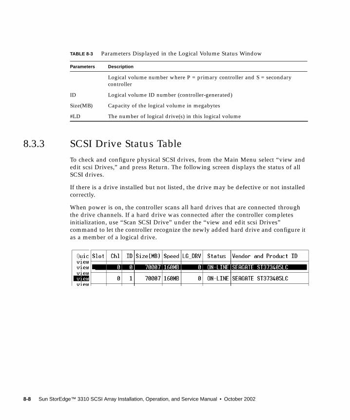
8.3.3 SCSI Drive Status TableTo check and configure physical SCSI drives, from the Main Menu select “view andedit scsi Drives,” and press Return. The following screen displays the status of allSCSI drives.
If there is a drive installed but not listed, the drive may be defective or not installedcorrectly.
When power is on, the controller scans all hard drives that are connected throughthe drive channels. If a hard drive was connected after the controller completesinitialization, use “Scan SCSI Drive” under the “view and edit scsi Drives”command to let the controller recognize the newly added hard drive and configure itas a member of a logical drive.
TABLE 8-3 Parameters Displayed in the Logical Volume Status Window
Parameters Description
Logical volume number where P = primary controller and S = secondarycontroller
ID Logical volume ID number (controller-generated)
Size(MB) Capacity of the logical volume in megabytes
#LD The number of logical drive(s) in this logical volume
8-8 Sun StorEdge™ 3310 SCSI Array Installation, Operation, and Service Manual • October 2002
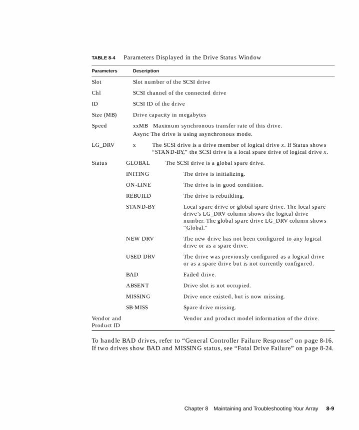
To handle BAD drives, refer to “General Controller Failure Response” on page 8-16.If two drives show BAD and MISSING status, see “Fatal Drive Failure” on page 8-24.
TABLE 8-4 Parameters Displayed in the Drive Status Window
Parameters Description
Slot Slot number of the SCSI drive
Chl SCSI channel of the connected drive
ID SCSI ID of the drive
Size (MB) Drive capacity in megabytes
Speed xxMB Maximum synchronous transfer rate of this drive.Async The drive is using asynchronous mode.
LG_DRV x The SCSI drive is a drive member of logical drive x. If Status shows“STAND-BY,” the SCSI drive is a local spare drive of logical drive x.
Status GLOBAL The SCSI drive is a global spare drive.
INITING The drive is initializing.
ON-LINE The drive is in good condition.
REBUILD The drive is rebuilding.
STAND-BY Local spare drive or global spare drive. The local sparedrive’s LG_DRV column shows the logical drivenumber. The global spare drive LG_DRV column shows“Global.”
NEW DRV The new drive has not been configured to any logicaldrive or as a spare drive.
USED DRV The drive was previously configured as a logical driveor as a spare drive but is not currently configured.
BAD Failed drive.
ABSENT Drive slot is not occupied.
MISSING Drive once existed, but is now missing.
SB-MISS Spare drive missing.
Vendor andProduct ID
Vendor and product model information of the drive.
Chapter 8 Maintaining and Troubleshooting Your Array 8-9
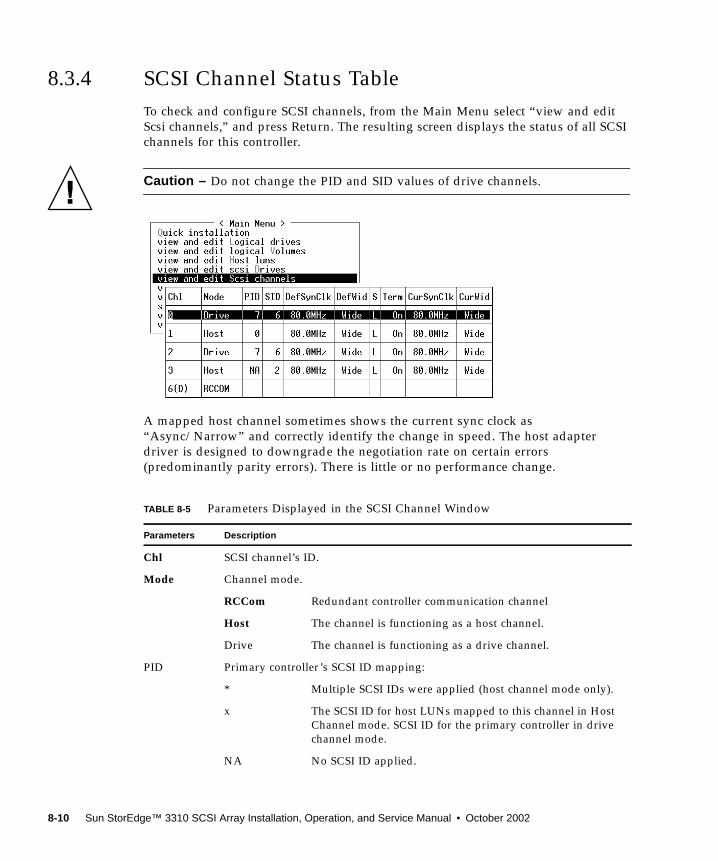
8.3.4 SCSI Channel Status TableTo check and configure SCSI channels, from the Main Menu select “view and editScsi channels,” and press Return. The resulting screen displays the status of all SCSIchannels for this controller.
Caution – Do not change the PID and SID values of drive channels.
A mapped host channel sometimes shows the current sync clock as“Async/Narrow” and correctly identify the change in speed. The host adapterdriver is designed to downgrade the negotiation rate on certain errors(predominantly parity errors). There is little or no performance change.
TABLE 8-5 Parameters Displayed in the SCSI Channel Window
Parameters Description
Chl SCSI channel’s ID.
Mode Channel mode.
RCCom Redundant controller communication channel
Host The channel is functioning as a host channel.
Drive The channel is functioning as a drive channel.
PID Primary controller’s SCSI ID mapping:
* Multiple SCSI IDs were applied (host channel mode only).
x The SCSI ID for host LUNs mapped to this channel in HostChannel mode. SCSI ID for the primary controller in drivechannel mode.
NA No SCSI ID applied.
8-10 Sun StorEdge™ 3310 SCSI Array Installation, Operation, and Service Manual • October 2002

SID Secondary controller’s SCSI ID mapping:
* Multiple SCSI IDs (Host Channel mode only).
x The SCSI ID for host LUNs mapped to this channel in hostchannel mode. SCSI ID for the secondary controller in drivechannel mode.
NA No SCSI ID applied
DefSynClk Default SCSI bus synchronous clock:
xx.xMHz Maximum synchronous transfer rate set to xx.x.
Async Channel is set for asynchronous transfers.
DefWid Default SCSI bus width:
Wide Channel is set to allow wide (16-bit) transfers.
Narrow Channel is set to allow narrow (8-bit) transfers.
S Signal:
S Single-ended
L LVD
F Fibre
Term Terminator status:
On Termination is enabled.
Off Termination is disabled.
NA For a redundant controller communications channel(RCCOM).
CurSynClk Current SCSI bus synchronous clock:
xx.xMHz The current speed at which the channel is communicating.
Async. The channel is communicating asynchronously or notdevice is detected.
(empty) The default SCSI bus synchronous clock has changed. Resetthe controller for changes to take effect.
CurWid Current SCSI bus width:
Wide The channel is currently servicing wide 16-bit transfers.
Narrow The channel is currently servicing wide 8-bit transfers.
(empty) The default SCSI bus width has changed. Reset thecontroller for the changes to take effect.
TABLE 8-5 Parameters Displayed in the SCSI Channel Window (Continued)
Parameters Description
Chapter 8 Maintaining and Troubleshooting Your Array 8-11
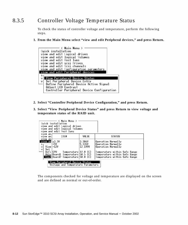
8.3.5 Controller Voltage Temperature StatusTo check the status of controller voltage and temperature, perform the followingsteps.
1. From the Main Menu select “view and edit Peripheral devices,” and press Return.
2. Select “Controller Peripheral Device Configuration,” and press Return.
3. Select “View Peripheral Device Status” and press Return to view voltage andtemperature status of the RAID unit.
The components checked for voltage and temperature are displayed on the screenand are defined as normal or out-of-order.
8-12 Sun StorEdge™ 3310 SCSI Array Installation, Operation, and Service Manual • October 2002
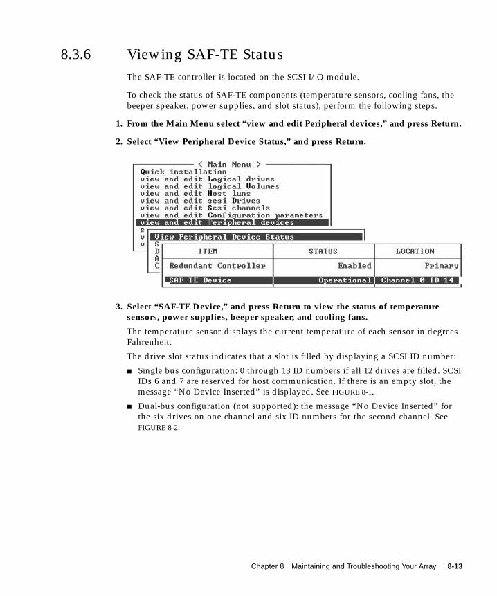
8.3.6 Viewing SAF-TE StatusThe SAF-TE controller is located on the SCSI I/O module.
To check the status of SAF-TE components (temperature sensors, cooling fans, thebeeper speaker, power supplies, and slot status), perform the following steps.
1. From the Main Menu select “view and edit Peripheral devices,” and press Return.
2. Select “View Peripheral Device Status,” and press Return.
3. Select “SAF-TE Device,” and press Return to view the status of temperaturesensors, power supplies, beeper speaker, and cooling fans.
The temperature sensor displays the current temperature of each sensor in degreesFahrenheit.
The drive slot status indicates that a slot is filled by displaying a SCSI ID number:
■ Single bus configuration: 0 through 13 ID numbers if all 12 drives are filled. SCSIIDs 6 and 7 are reserved for host communication. If there is an empty slot, themessage “No Device Inserted” is displayed. See FIGURE 8-1.
■ Dual-bus configuration (not supported): the message “No Device Inserted” forthe six drives on one channel and six ID numbers for the second channel. SeeFIGURE 8-2.
Chapter 8 Maintaining and Troubleshooting Your Array 8-13
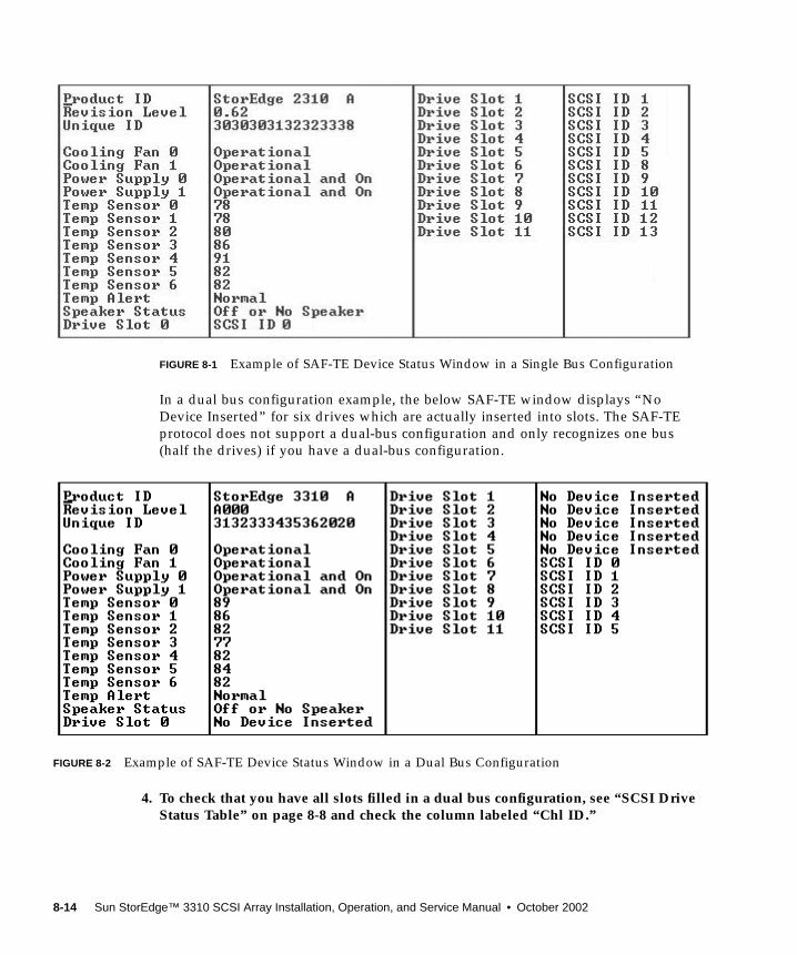
FIGURE 8-1 Example of SAF-TE Device Status Window in a Single Bus Configuration
In a dual bus configuration example, the below SAF-TE window displays “NoDevice Inserted” for six drives which are actually inserted into slots. The SAF-TEprotocol does not support a dual-bus configuration and only recognizes one bus(half the drives) if you have a dual-bus configuration.
FIGURE 8-2 Example of SAF-TE Device Status Window in a Dual Bus Configuration
4. To check that you have all slots filled in a dual bus configuration, see “SCSI DriveStatus Table” on page 8-8 and check the column labeled “Chl ID.”
8-14 Sun StorEdge™ 3310 SCSI Array Installation, Operation, and Service Manual • October 2002
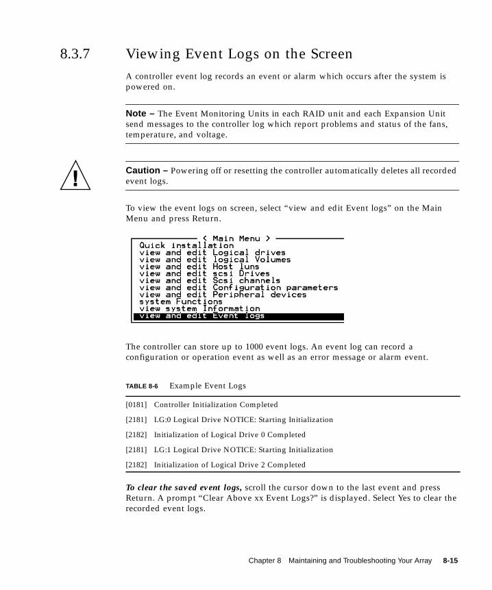
8.3.7 Viewing Event Logs on the ScreenA controller event log records an event or alarm which occurs after the system ispowered on.
Note – The Event Monitoring Units in each RAID unit and each Expansion Unitsend messages to the controller log which report problems and status of the fans,temperature, and voltage.
Caution – Powering off or resetting the controller automatically deletes all recordedevent logs.
To view the event logs on screen, select “view and edit Event logs” on the MainMenu and press Return.
The controller can store up to 1000 event logs. An event log can record aconfiguration or operation event as well as an error message or alarm event.
To clear the saved event logs, scroll the cursor down to the last event and pressReturn. A prompt “Clear Above xx Event Logs?” is displayed. Select Yes to clear therecorded event logs.
TABLE 8-6 Example Event Logs
[0181] Controller Initialization Completed
[2181] LG:0 Logical Drive NOTICE: Starting Initialization
[2182] Initialization of Logical Drive 0 Completed
[2181] LG:1 Logical Drive NOTICE: Starting Initialization
[2182] Initialization of Logical Drive 2 Completed
Chapter 8 Maintaining and Troubleshooting Your Array 8-15
8.4 Controller Failure Symptoms, LogicalDrive Rebuild, and ReplacementController failure symptoms are as follows:
■ The surviving controller sounds an audible alarm.
■ The center LED (status symbol) flashes yellow on the failed controller.
■ The surviving controller sends event messages announcing the controller failureof the other controller.
A warning message, “SCSI Bus Reset Issued” is displayed for each of the SCSIchannels. In addition, an alert message says “Redundant Controller FailureDetected.”
8.4.1 General Controller Failure ResponseIf one controller in the redundant controller configuration fails, the survivingcontroller temporarily takes over for the failed controller until it is replaced.
A failed controller is managed by the surviving controller which disables anddisconnects from its counterpart while gaining access to all the signal paths. Thesurviving controller then manages the ensuing event notifications and takes over allprocesses. It is always the primary controller regardless of its original status, andany replacement controller afterward assumes the role of the secondary controller.
The failover and failback processes are completely transparent to the host.Controllers are hot-swappable, and replacing a failed unit takes only a few minutes.
To maintain your redundant controller configuration, replace the failed controller assoon as possible. For details, see “Replacing a Controller Module” on page 9-4.
8-16 Sun StorEdge™ 3310 SCSI Array Installation, Operation, and Service Manual • October 2002
8.4.2 Automatic Logical Drive RebuildRebuild with Spare: When a member drive in a logical drive fails, the controller firstexamines whether there is a local spare drive assigned to this logical drive. If yes, itautomatically starts to rebuild the data of the failed disk to it.
If there is no local spare available, the controller searches for a global spare. If thereis a global spare, it automatically uses it to rebuild the logical drive.
Failed Drive Swap Detect: If neither a local spare drive nor a global spare drive isavailable, and the “Periodic Auto-Detect Failure Drive Swap Check Time” is“disabled,” the controller does not attempt to rebuild unless you apply a forced-manual rebuild.
To enable this feature, go to the Main Menu choose “view and edit Configurationparameters,” then select “Drive-side SCSI Parameters,” and select “Periodic Auto-Detect Failure Drive Swap Check Time.”
When the “Periodic Auto-Detect Failure Drive Swap Check Time” is “Enabled” (thatis, a check time interval has been selected), the controller detects whether or not thefailed drive has been swapped (by checking the failed drive's channel/ID). Once thefailed drive has been swapped, the rebuild begins immediately.
If the failed drive is not swapped but a local spare is added to the logical drive, therebuild begins with the spare.
For a flowchart of automatic rebuild, see FIGURE 8-3.
8.4.3 Manual RebuildWhen a user applies forced-manual rebuild, the controller first examines whetherthere is any local spare assigned to the logical drive. If yes, it automatically starts torebuild.
If there is no local spare available, the controller will search for a global spare. Ifthere is a global spare, the logical drive rebuild will begin. See FIGURE 8-4.
If neither local spare nor global spare is available, the controller will examine theSCSI channel and ID of the failed drive. After the failed drive has been replaced bya healthy one, the logical drive rebuild begins on the new drive. If there is no driveavailable for rebuilding, the controller will not attempt to rebuild until the userapplies another forced-manual rebuild.
Chapter 8 Maintaining and Troubleshooting Your Array 8-17
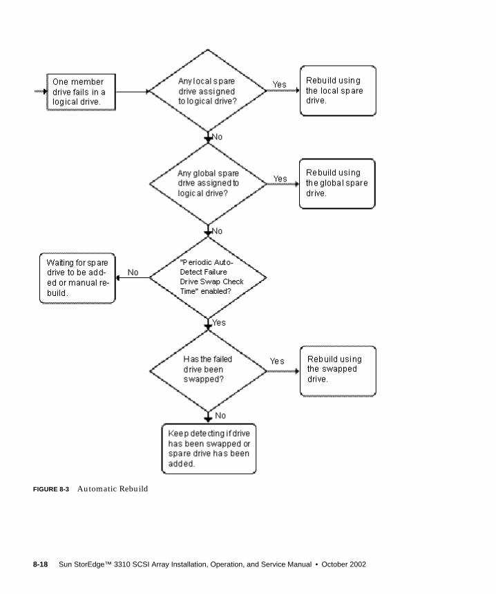
FIGURE 8-3 Automatic Rebuild
8-18 Sun StorEdge™ 3310 SCSI Array Installation, Operation, and Service Manual • October 2002
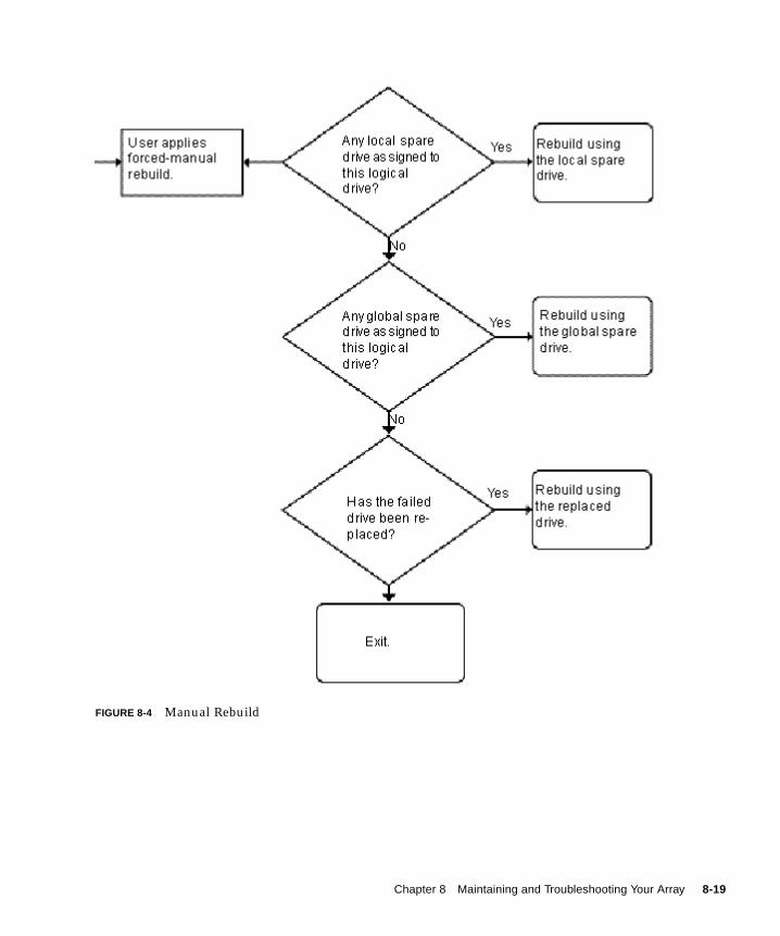
FIGURE 8-4 Manual Rebuild
Chapter 8 Maintaining and Troubleshooting Your Array 8-19
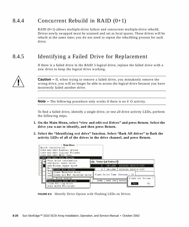
8.4.4 Concurrent Rebuild in RAID (0+1)RAID (0+1) allows multiple-drive failure and concurrent multiple-drive rebuild.Drives newly swapped must be scanned and set as local spares. These drives will berebuilt at the same time; you do not need to repeat the rebuilding process for eachdrive.
8.4.5 Identifying a Failed Drive for ReplacementIf there is a failed drive in the RAID 5 logical drive, replace the failed drive with anew drive to keep the logical drive working.
Caution – If, when trying to remove a failed drive, you mistakenly remove thewrong drive, you will no longer be able to access the logical drive because you haveincorrectly failed another drive.
Note – The following procedure only works if there is no I/O activity.
To find a failed drive, identify a single drive, or test all drive activity LEDs, performthe following steps.
1. On the Main Menu, select “view and edit scsi Drives” and press Return. Select thedrive you want to identify, and then press Return.
2. Select the “Identifying scsi drive” function. Select “flash All drives” to flash theactivity LEDs of all of the drives in the drive channel, and press Return.
FIGURE 8-5 Identify Drive Option with Flashing LEDs on Drives
8-20 Sun StorEdge™ 3310 SCSI Array Installation, Operation, and Service Manual • October 2002
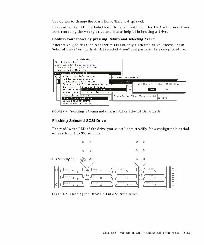
The option to change the Flash Drive Time is displayed.
The read/write LED of a failed hard drive will not light. This LED will prevent youfrom removing the wrong drive and is also helpful in locating a drive.
3. Confirm your choice by pressing Return and selecting “Yes.”
Alternatively, to flash the read/write LED of only a selected drive, choose “flashSelected drive” or “flash all But selected drive” and perform the same procedure.
FIGURE 8-6 Selecting a Command to Flash All or Selected Drive LEDs
Flashing Selected SCSI Drive
The read/write LED of the drive you select lights steadily for a configurable periodof time from 1 to 999 seconds.
FIGURE 8-7 Flashing the Drive LED of a Selected Drive
Disk 1
Disk 2
Disk 3
Disk 4
Disk 5
Disk 6
Disk 7
Disk 8
Disk 9
Disk 10
Disk 11
Disk 12
LED steadily on
Chapter 8 Maintaining and Troubleshooting Your Array 8-21
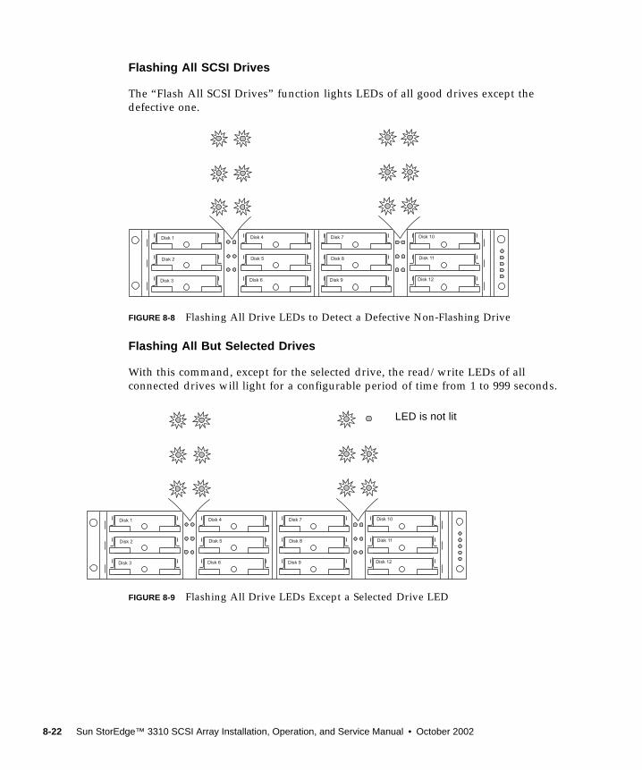
Flashing All SCSI Drives
The “Flash All SCSI Drives” function lights LEDs of all good drives except thedefective one.
FIGURE 8-8 Flashing All Drive LEDs to Detect a Defective Non-Flashing Drive
Flashing All But Selected Drives
With this command, except for the selected drive, the read/write LEDs of allconnected drives will light for a configurable period of time from 1 to 999 seconds.
FIGURE 8-9 Flashing All Drive LEDs Except a Selected Drive LED
Disk 1
Disk 2
Disk 3
Disk 4
Disk 5
Disk 6
Disk 7
Disk 8
Disk 9
Disk 10
Disk 11
Disk 12
Disk 1
Disk 2
Disk 3
Disk 4
Disk 5
Disk 6
Disk 7
Disk 8
Disk 9
Disk 10
Disk 11
Disk 12
LED is not lit
8-22 Sun StorEdge™ 3310 SCSI Array Installation, Operation, and Service Manual • October 2002
8.4.6 Restoring Your Configuration (NVRAM) From aFileIf you have saved a configuration file and want to apply the same configuration toanother array or reapply it to the array that had the configuration originally, youmust be certain that the channels and SCSI IDs in the configuration file are correctfor the array where you are restoring the configuration.
The NVRAM configuration file will restore all configuration settings (channelsettings, host IDs, etc.) but does not rebuild logical drives.
To save a configuration file, see “Saving Configuration (NVRAM) to a Disk” onpage 6-31.
Caution – If the channels or SCIS IDs are not a correct match for the array, you willlose access to the mismatched channels or drives when you restore the configurationwith the configuration file.
Note – In the Configuration Service program, you can save a configuration file thatcan restore all configurations and rebuild all logical drives. However, it will alsoerase all data when it rebuilds all logical drives, so operation is performed onlywhen no data has been stored or all data has been transferred to another array.
To restore configuration settings from a saved NVRAM file, perform the followingsteps.
1. From the Main Menu choose “system Functions.”
2. Select “Controller maintenance” and press Return.
3. Select “Restore NVRAM from disks,” and press Return.
4. Press Yes to confirm.
A prompt will notify you that the controller NVRAM data has been successfullyrestored from disks.
Chapter 8 Maintaining and Troubleshooting Your Array 8-23

8.4.7 Fatal Drive FailureWith the redundant RAID array system, your system is protected with the RAIDparity drive and by the default global spare (you may have more than one).
Note – A FATAL FAIL status occurs when there is one more drive failing than thenumber of spare drives available for the logical drive. If a logical drive has twoglobal spares available, then three failed drives must occur for FATAL FAIL status.
In an extremely rare occurrence where two or more drives appear to fail at the sametime, perform the following steps.
1. Discontinue all input/output activity immediately.
2. To cancel the beeping alarm, use a paperclip to press the Reset button (below theLEDs on the front-right ear of the array).
3. Physically check that all the drives are firmly seated in the array and that nonehave been partially or completely removed.
4. Check again the firmware Main Menu and check the “view and edit Logicaldrives,” and look for:
Status: FAILED DRV (one failed drive) orStatus: FATAL FAIL (two or more failed drives)
5. Highlight the logical drive, press Return, and select “view scsi drives.”
If two physical drives have a problem, one drive will have a BAD status and onedrive will have a MISSING. The MISSING status is a reminder that one of the drivesmay be a “false” failure. The status does not tell you which drive might be a falsefailure.
6. Do one of the following:
■ Choose “system Functions” from the Main Menu and press Return. Select “Resetcontroller,” and press Return.
or
■ Power off the array. Wait five seconds, and power on the array.
8-24 Sun StorEdge™ 3310 SCSI Array Installation, Operation, and Service Manual • October 2002
7. Repeat steps 4 and 5 to check the logical and SCSI drive status.
After resetting the controller, if there is a false bad drive, the array will automaticallystart rebuilding the failed RAID set.
If the array does not automatically start rebuilding the RAID set, check the statusunder “view and edit Logical drives.”
■ If the status is “FAILED DRV,” manually rebuild the RAID set (refer to “ManualRebuild” on page 8-17).
■ If the status is still “FATAL FAIL,” you have lost all data on the logical drive andmust re-create the logical drive. Proceed with the following procedures:
■ “Replacing a Drive” on page 9-3 for the failed drive
■ “Deleting a Logical Drive” (Section 3.7 in the Sun StorEdge 3310 SCSI RAIDFirmware User Guide)
■ “Creating Logical Drive(s) (optional)” on page 6-14
For additional troubleshooting tips, refer to the Sun StorEdge 3310 SCSI Array ReleaseNotes located at:
www.sun.com/products-n-solutions/hardware/docs/Network_Storage_Solutions/Workgroup/3310
8.5 Upgrading Firmware
8.5.1 Review Firmware Upgrade FeaturesThe following firmware upgrade features apply to the controller firmware:
■ Redundant Controller Rolling Firmware Upgrade
When download is performed on a dual-controller system, firmware is flashedonto both controllers without interrupting host I/Os. When the download processis complete, the primary controller will reset and let the secondary controller takeover the service temporarily. When the primary controller comes back on-line, thesecondary controller will hand over the workload and then reset itself for the newfirmware to take effect. The rolling upgrade is automatically performed bycontroller firmware, and the user's intervention is not necessary.
Chapter 8 Maintaining and Troubleshooting Your Array 8-25
■ Automatically Synchronized Controller Firmware Versions
A controller that replaces a failed unit in a dual-controller system is often runninga newer release of firmware version. To maintain compatibility, the survivingprimary controller will automatically update the firmware running on thereplacement secondary controller to the firmware version of the primarycontroller.
■ Upgrading Firmware Using the Serial Port Connections (from Windows hosts)
The firmware can be downloaded to the RAID controller by using an ANSI/VT-100 compatible emulation program. The emulation program must support theZMODEM file transfer protocol. Emulation programs such as HyperTerminal,Telix, and PROCOMM Plus can perform the firmware upgrade.
8.5.2 Downloading Firmware UpgradesFor a fast and easy download of new versions of controller firmware, disk drivefirmware, and SAF-TE firmware, use one of the following tools:
■ Sun StorEdge 3310 CLI (with an in-band SCSI connection, for Solaris andWindows hosts)
■ Sun StorEdge 3310 Configuration Service program (with an in-band SCSIconnection, for Solaris and Windows hosts)
■ Firmware application (for controller firmware download only from a Windowshost with an out-of-band serial port connection)
Note – To download firmware to disk drives or SAF-TE firmware to a JBOD directlyattached to a host, you must use the Sun StorEdge 3310 SCSI Configuration Serviceprogram.
Caution – You should not use both in-band and out-of-band connections at thesame time to manage the array or you might cause conflicts between multipleoperations.
8-26 Sun StorEdge™ 3310 SCSI Array Installation, Operation, and Service Manual • October 2002
Controller Firmware Upgrade from Firmware Application
You can also use a Windows terminal emulation session with ZMODEM capabilitiesto access the firmware application. To upgrade the RAID controller firmwarethrough the serial port and the firmware application, perform the following steps.
1. Establish the serial port connection.
■ To upgrade both the boot record and the firmware binary, perform step 2.
■ To upgrade only the firmware binary, perform step 3.
2. Upgrade both boot record and firmware binaries with the following steps.
a. From the Main Menu scroll down to “System Functions.”
b. Go to “Controller Maintenance” and select “Advanced Maintenance.”
c. Select “Download Boot Record and Firmware.”
d. Set ZMODEM as the file transfer protocol of your emulation software.
e. Send the Boot Record Binary to the controller:
In HyperTerminal, go to the “Transfer” menu and choose “Send file.” If you arenot using HyperTerminal, choose “Upload” or “Send” (depending on thesoftware).
f. After the Boot Record has been downloaded, send the Firmware Binary to thecontroller:
In HyperTerminal, go to the “Transfer” menu and choose “Send file.” If you arenot using HyperTerminal, choose “Upload” or “Send” (depending on thesoftware).
When the Firmware completes downloading, the controller will automaticallyreset itself.
3. Upgrade the firmware binary only with the following steps.
a. From the Main Menu scroll down to “System Functions.”
b. Go to “Controller Maintenance” and select “Advanced Maintenance.”
c. Choose “Download Firmware.”
d. Set ZMODEM as the file transfer protocol of your emulation software.
e. Send the Firmware Binary to the controller:
In HyperTerminal, select “Send file.” If you are not using Hyper, choose “Upload”or “Send” (depending on the software).
When the Firmware completes downloading, the controller will automaticallyreset itself.
Chapter 8 Maintaining and Troubleshooting Your Array 8-27

8-28 Sun StorEdge™ 3310 SCSI Array Installation, Operation, and Service Manual • October 2002
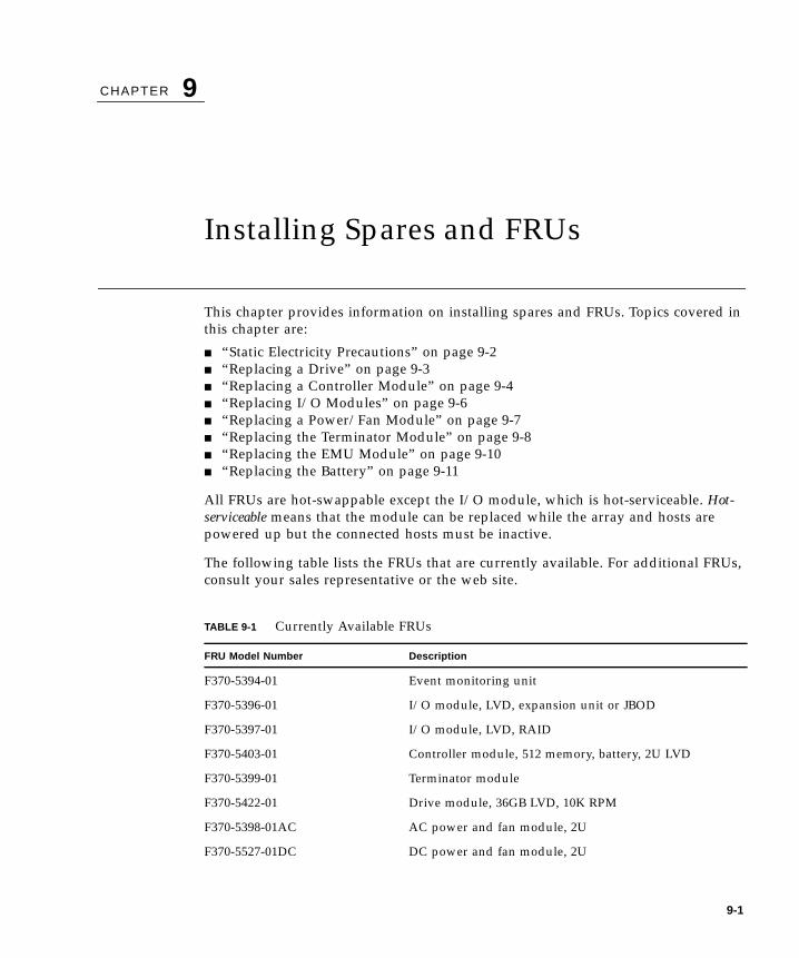
CHAPTER 9
Installing Spares and FRUs
This chapter provides information on installing spares and FRUs. Topics covered inthis chapter are:
■ “Static Electricity Precautions” on page 9-2■ “Replacing a Drive” on page 9-3■ “Replacing a Controller Module” on page 9-4■ “Replacing I/O Modules” on page 9-6■ “Replacing a Power/Fan Module” on page 9-7■ “Replacing the Terminator Module” on page 9-8■ “Replacing the EMU Module” on page 9-10■ “Replacing the Battery” on page 9-11
All FRUs are hot-swappable except the I/O module, which is hot-serviceable. Hot-serviceable means that the module can be replaced while the array and hosts arepowered up but the connected hosts must be inactive.
The following table lists the FRUs that are currently available. For additional FRUs,consult your sales representative or the web site.
TABLE 9-1 Currently Available FRUs
FRU Model Number Description
F370-5394-01 Event monitoring unit
F370-5396-01 I/O module, LVD, expansion unit or JBOD
F370-5397-01 I/O module, LVD, RAID
F370-5403-01 Controller module, 512 memory, battery, 2U LVD
F370-5399-01 Terminator module
F370-5422-01 Drive module, 36GB LVD, 10K RPM
F370-5398-01AC AC power and fan module, 2U
F370-5527-01DC DC power and fan module, 2U
9-1
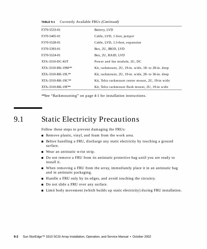
**See “Rackmounting” on page 4-1 for installation instructions.
9.1 Static Electricity PrecautionsFollow these steps to prevent damaging the FRUs:
■ Remove plastic, vinyl, and foam from the work area.
■ Before handling a FRU, discharge any static electricity by touching a groundsurface.
■ Wear an antistatic wrist strip.
■ Do not remove a FRU from its antistatic protective bag until you are ready toinstall it.
■ When removing a FRU from the array, immediately place it in an antistatic bagand in antistatic packaging.
■ Handle a FRU only by its edges, and avoid touching the circuitry.
■ Do not slide a FRU over any surface.
■ Limit body movement (which builds up static electricity) during FRU installation.
F370-5533-01 Battery, LVD
F370-5405-01 Cable, LVD, 1-foot, jumper
F370-5528-01 Cable, LVD, 1.5-foot, expansion
F370-5393-01 Box, 2U, JBOD, LVD
F370-5524-01 Box, 2U, RAID, LVD
XTA-3310-DC-KIT Power and fan module, 2U, DC
XTA-3310-RK-19M** Kit, rackmount, 2U, 19-in. wide, 18- to 28-in. deep
XTA-3310-RK-19L** Kit, rackmount, 2U, 19-in. wide, 28- to 36-in. deep
XTA-3310-RK-19C** Kit, Telco rackmount center mount, 2U, 19-in wide
XTA-3310-RK-19F** Kit, Telco rackmount flush mount, 2U, 19-in wide
TABLE 9-1 Currently Available FRUs (Continued)
9-2 Sun StorEdge™ 3310 SCSI Array Installation, Operation, and Service Manual • October 2002
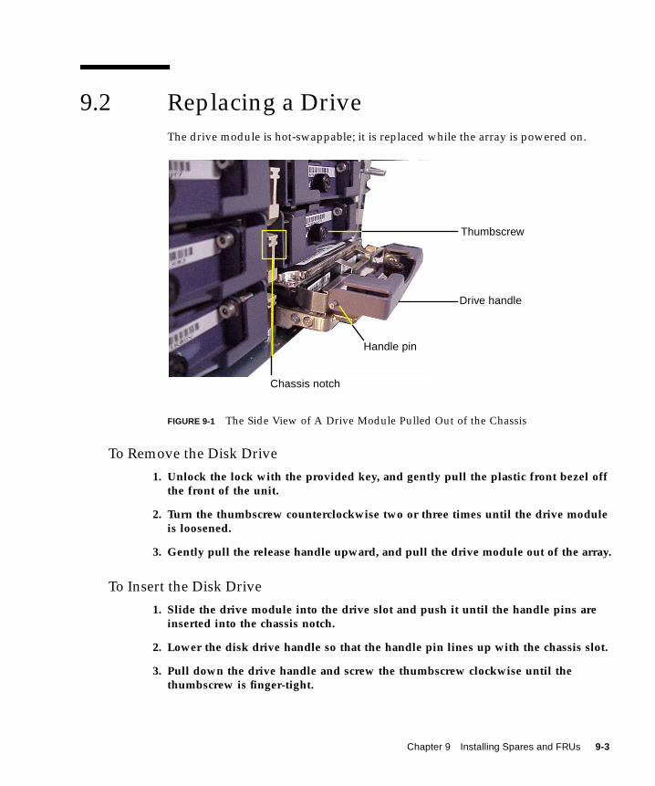
9.2 Replacing a DriveThe drive module is hot-swappable; it is replaced while the array is powered on.
FIGURE 9-1 The Side View of A Drive Module Pulled Out of the Chassis
To Remove the Disk Drive
1. Unlock the lock with the provided key, and gently pull the plastic front bezel offthe front of the unit.
2. Turn the thumbscrew counterclockwise two or three times until the drive moduleis loosened.
3. Gently pull the release handle upward, and pull the drive module out of the array.
To Insert the Disk Drive
1. Slide the drive module into the drive slot and push it until the handle pins areinserted into the chassis notch.
2. Lower the disk drive handle so that the handle pin lines up with the chassis slot.
3. Pull down the drive handle and screw the thumbscrew clockwise until thethumbscrew is finger-tight.
Handle pin
Chassis notch
Thumbscrew
Drive handle
Chapter 9 Installing Spares and FRUs 9-3
9.3 Replacing a Controller ModuleBe sure to follow “Static Electricity Precautions” on page 9-2.
Caution – If you power off the array and replace a controller, the replacementcontroller could become the primary controller and overwrite any configurationsettings previously set. Before replacing a RAID controller, save the configurationsettings to NVRAM. If power is removed before you replace a RAID controller, thesettings can be restored from NVRAM.
The replacement procedures for the RAID controller follow.
To Save the Configuration Settings to NVRAM
1. From the firmware application Main Menu, choose “system Functions.”
2. Use the arrow keys to scroll down, and select “controller maintenance,” thenselect “save NVRAM to disks” and press Return.
3. Choose Yes to confirm. A prompt will inform you that NVRAM information hasbeen successfully saved.
To Remove a Controller Module
1. Keep the array powered on.
2. Turn the thumbscrews on the left and right sides of the controller modulecounterclockwise until the thumbscrews are disengaged from the chassis.
3. Hold the thumbscrews, and pull out the controller module.
To Insert a Controller Module
1. Keep the array powered on. Gently slide the controller module into the unit untilit clicks and is seated in the backplane.
Caution – Be sure that the controller module is properly inserted into the guiderails.
2. Turn the thumbscrews on the left and right side of the controller moduleclockwise until finger-tight, to secure the module and to make the module’s front-panel flush with the chassis.
The new controller will automatically become the secondary controller.
9-4 Sun StorEdge™ 3310 SCSI Array Installation, Operation, and Service Manual • October 2002
3. If the array was powered off during the controller replacement, restoreconfiguration settings from NVRAM if the new controller replaced an oldcontroller:
a. From the firmware application Main Menu, choose “system Functions.” Select“Controller maintenance” and press Return.
b. Select “Restore NVRAM from disks” and press Return. Press Yes to confirm.
c. A prompt will notify you that the controller NVRAM data has beensuccessfully restored from disks.
If Powered Off During Replacement or a Single-Controller Array Replacement
If the array was powered off during the controller replacement or if you replaced acontroller in a single-controller configuration, perform the following importantsteps.
1. Restore configuration settings from NVRAM if the new controller replaced an oldcontroller:
a. On the firmware main menu, select “system Functions,” select “Controllermaintenance,” and press Return.
b. Select “Restore NVRAM from disks” and press Return. Press Yes to confirm.
2. Set the parameter called the "Controller Unique Identifier" to the correct value:
a. On the firmware main menu, select “view and edit Configuration parameters,”then select “Controller Parameters,” and press Return.
b. From the Controller Parameters menu, select “Controller Unique Identifier<hex>” and press Return. Type in the value 0 (to automatically read the chassisserial number from the midplane) or type the hex value for the original serialnumber of the chassis (used when the midplane has been replaced).
The Controller Unique Identifier is used to create Ethernet Addresses and WorldWide Names. The value 0 is immediately replaced with the hex value of thechassis serial number. A non-zero value should only be specified if the chassis hasbeen replaced but the original chassis serial number must be retained; this featureis especially important in a Sun Cluster environment to maintain the same diskdevice names in a cluster.
3. To implement the revised configuration settings from step 1 or 2, select “systemFunctions” on the Main Menu, select “Reset controller” and press Return.
Chapter 9 Installing Spares and FRUs 9-5
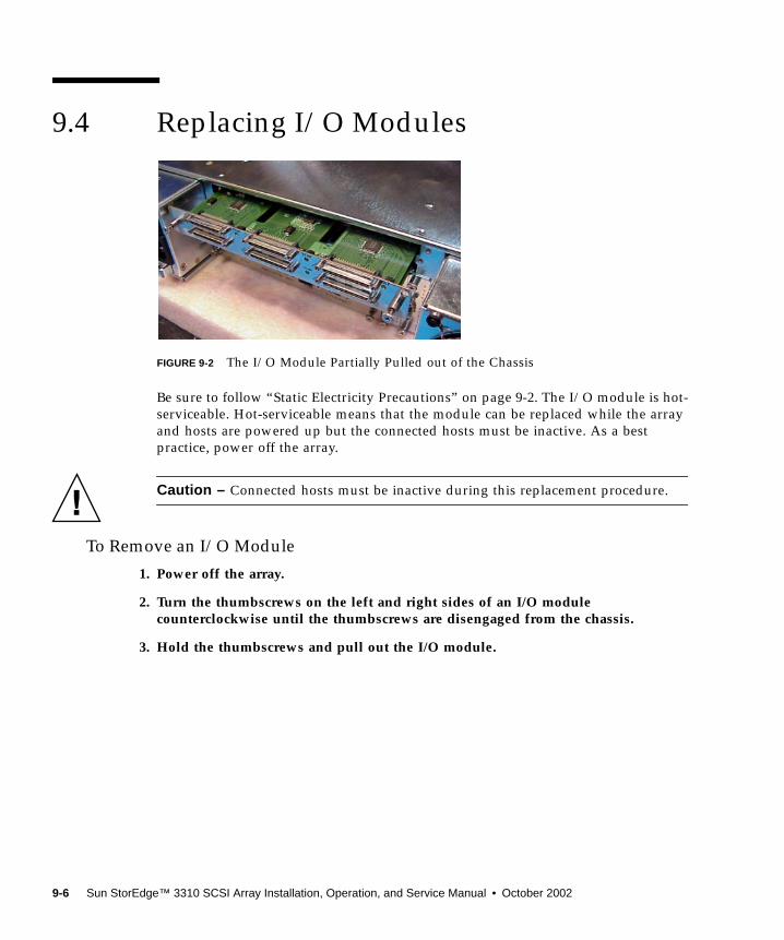
9.4 Replacing I/O Modules
FIGURE 9-2 The I/O Module Partially Pulled out of the Chassis
Be sure to follow “Static Electricity Precautions” on page 9-2. The I/O module is hot-serviceable. Hot-serviceable means that the module can be replaced while the arrayand hosts are powered up but the connected hosts must be inactive. As a bestpractice, power off the array.
Caution – Connected hosts must be inactive during this replacement procedure.
To Remove an I/O Module
1. Power off the array.
2. Turn the thumbscrews on the left and right sides of an I/O modulecounterclockwise until the thumbscrews are disengaged from the chassis.
3. Hold the thumbscrews and pull out the I/O module.
9-6 Sun StorEdge™ 3310 SCSI Array Installation, Operation, and Service Manual • October 2002

To Insert an I/O Module
1. Power off the array.
2. Slide the I/O module into the chassis until the module is firmly seated in thebackplane, and the module’s front-panel is flush with the chassis.
Caution – Be sure that the I/O module is properly inserted into the guide rails.
3. Turn the thumbscrews on the left and right sides of the I/O module clockwiseuntil the thumbscrews are finger-tight, to secure the module.
9.5 Replacing a Power/Fan Module
To Remove a Fan/Power Supply Module
1. Be sure to follow “Static Electricity Precautions” on page 9-2. Turn off the powerand remove the power cable.
2. Turn the thumbscrew at the top of the power supply latch counterclockwise untilthe thumbscrew is disengaged from the power supply.
FIGURE 9-3 The Power Supply Partially Pulled out of the Chassis
3. Pull the latch forward about 45 degrees to disconnect the power supply/fanmodule from the midplane.
4. Use the power supply handle to pull the power supply/fan module out of thechassis.
Latch
Thumbscrew
Handle
Chapter 9 Installing Spares and FRUs 9-7
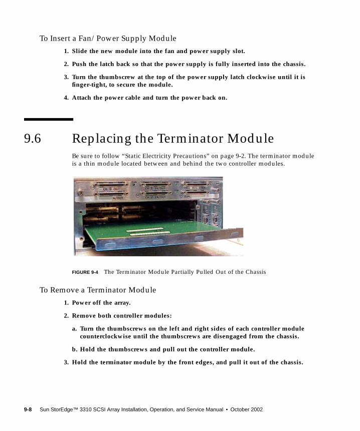
To Insert a Fan/Power Supply Module
1. Slide the new module into the fan and power supply slot.
2. Push the latch back so that the power supply is fully inserted into the chassis.
3. Turn the thumbscrew at the top of the power supply latch clockwise until it isfinger-tight, to secure the module.
4. Attach the power cable and turn the power back on.
9.6 Replacing the Terminator ModuleBe sure to follow “Static Electricity Precautions” on page 9-2. The terminator moduleis a thin module located between and behind the two controller modules.
FIGURE 9-4 The Terminator Module Partially Pulled Out of the Chassis
To Remove a Terminator Module
1. Power off the array.
2. Remove both controller modules:
a. Turn the thumbscrews on the left and right sides of each controller modulecounterclockwise until the thumbscrews are disengaged from the chassis.
b. Hold the thumbscrews and pull out the controller module.
3. Hold the terminator module by the front edges, and pull it out of the chassis.
9-8 Sun StorEdge™ 3310 SCSI Array Installation, Operation, and Service Manual • October 2002
To Insert a Terminator Module
1. Keep the power turned off.
2. Slide the terminator module into the chassis until it clicks and is seated in thebackplane.
Caution – Be sure that the terminator module is properly inserted into the guiderails.
3. Reinstall both controller modules:
a. Gently slide each controller module into the unit until it is seated in thebackplane.
b. Turn the thumbscrews on the left and right side of the controller moduleclockwise until finger-tight, to secure the module.
4. Power on the array.
Chapter 9 Installing Spares and FRUs 9-9
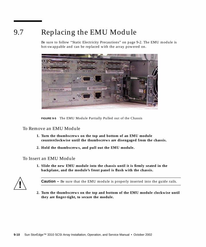
9.7 Replacing the EMU ModuleBe sure to follow “Static Electricity Precautions” on page 9-2. The EMU module ishot-swappable and can be replaced with the array powered on.
FIGURE 9-5 The EMU Module Partially Pulled out of the Chassis
To Remove an EMU Module
1. Turn the thumbscrews on the top and bottom of an EMU modulecounterclockwise until the thumbscrews are disengaged from the chassis.
2. Hold the thumbscrews, and pull out the EMU module.
To Insert an EMU Module
1. Slide the new EMU module into the chassis until it is firmly seated in thebackplane, and the module’s front panel is flush with the chassis.
Caution – Be sure that the EMU module is properly inserted into the guide rails.
2. Turn the thumbscrews on the top and bottom of the EMU module clockwise untilthey are finger-tight, to secure the module.
9-10 Sun StorEdge™ 3310 SCSI Array Installation, Operation, and Service Manual • October 2002
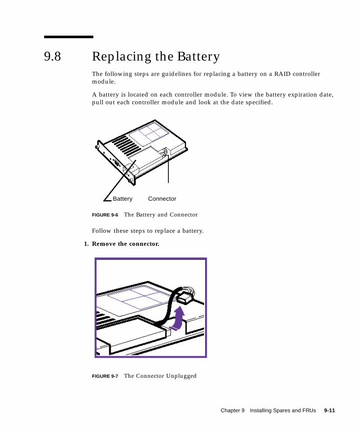
9.8 Replacing the BatteryThe following steps are guidelines for replacing a battery on a RAID controllermodule.
A battery is located on each controller module. To view the battery expiration date,pull out each controller module and look at the date specified.
FIGURE 9-6 The Battery and Connector
Follow these steps to replace a battery.
1. Remove the connector.
FIGURE 9-7 The Connector Unplugged
Battery Connector
Chapter 9 Installing Spares and FRUs 9-11
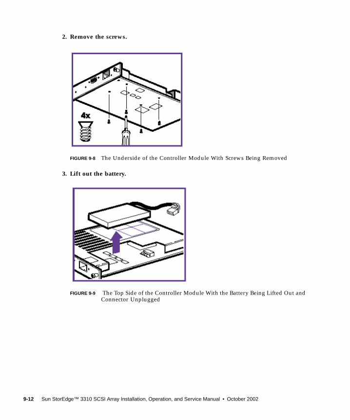
2. Remove the screws.
FIGURE 9-8 The Underside of the Controller Module With Screws Being Removed
3. Lift out the battery.
FIGURE 9-9 The Top Side of the Controller Module With the Battery Being Lifted Out andConnector Unplugged
9-12 Sun StorEdge™ 3310 SCSI Array Installation, Operation, and Service Manual • October 2002
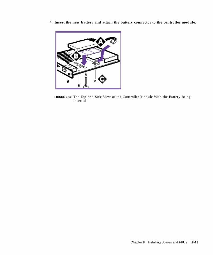
4. Insert the new battery and attach the battery connector to the controller module.
FIGURE 9-10 The Top and Side View of the Controller Module With the Battery BeingInserted
Chapter 9 Installing Spares and FRUs 9-13

9-14 Sun StorEdge™ 3310 SCSI Array Installation, Operation, and Service Manual • October 2002
APPENDIX A
SCSI Array Specifications
This appendix provides the specifications for the Sun StorEdge 3310 SCSI array. Thetopics covered are:
■ “Summary of Sun StorEdge 3310 SCSI Array Specifications” on page A-2
■ “Agency Approvals and Standards” on page A-3
A-1
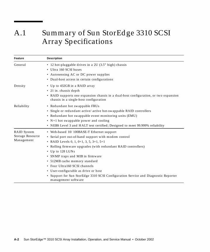
A.1 Summary of Sun StorEdge 3310 SCSIArray Specifications
Feature Description
General • 12 hot-pluggable drives in a 2U (3.5” high) chassis• Ultra 160 SCSI buses• Autosensing AC or DC power supplies• Dual-host access in certain configurations
Density • Up to 432GB in a RAID array• 21 in. chassis depth• RAID supports one expansion chassis in a dual-host configuration, or two expansion
chassis in a single-host configuration
Reliability • Redundant hot swappable FRUs• Single or redundant active/active hot-swappable RAID controllers• Redundant hot swappable event monitoring units (EMU)• N+1 hot swappable power and cooling• NEBS Level 3 and HALT test certified; Designed to meet 99.999% reliability
RAID SystemStorage ResourceManagement
• Web-based 10/100BASE-T Ethernet support• Serial port out-of-band support with modem control• RAID Levels 0, 1, 0+1, 3, 5, 3+1, 5+1• Rolling firmware upgrades (with redundant RAID controllers)• Up to 128 LUNs• SNMP traps and MIB in firmware• 512MB cache memory standard• Four Ultra160 SCSI channels• User-configurable as drive or host• Support for Sun StorEdge 3310 SCSI Configuration Service and Diagnostic Reporter
management software
A-2 Sun StorEdge™ 3310 SCSI Array Installation, Operation, and Service Manual • October 2002
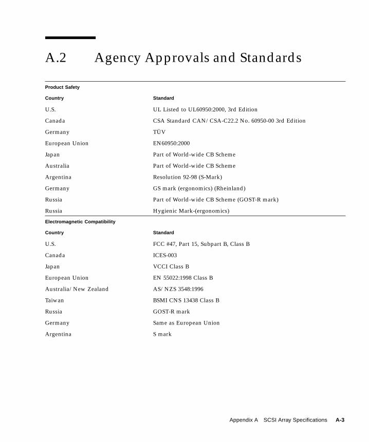
A.2 Agency Approvals and Standards
Product Safety
Country Standard
U.S. UL Listed to UL60950:2000, 3rd Edition
Canada CSA Standard CAN/CSA-C22.2 No. 60950-00 3rd Edition
Germany TÜV
European Union EN60950:2000
Japan Part of World-wide CB Scheme
Australia Part of World-wide CB Scheme
Argentina Resolution 92-98 (S-Mark)
Germany GS mark (ergonomics) (Rheinland)
Russia Part of World-wide CB Scheme (GOST-R mark)
Russia Hygienic Mark-(ergonomics)
Electromagnetic Compatibility
Country Standard
U.S. FCC #47, Part 15, Subpart B, Class B
Canada ICES-003
Japan VCCI Class B
European Union EN 55022:1998 Class B
Australia/New Zealand AS/NZS 3548:1996
Taiwan BSMI CNS 13438 Class B
Russia GOST-R mark
Germany Same as European Union
Argentina S mark
Appendix A SCSI Array Specifications A-3
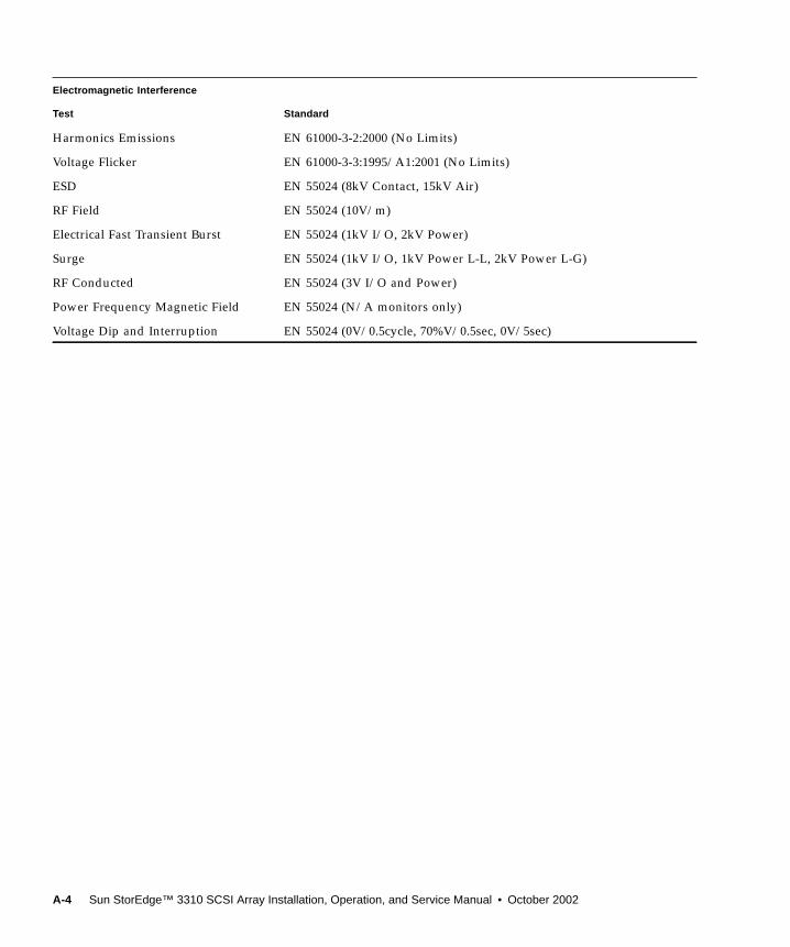
Electromagnetic Interference
Test Standard
Harmonics Emissions EN 61000-3-2:2000 (No Limits)
Voltage Flicker EN 61000-3-3:1995/A1:2001 (No Limits)
ESD EN 55024 (8kV Contact, 15kV Air)
RF Field EN 55024 (10V/m)
Electrical Fast Transient Burst EN 55024 (1kV I/O, 2kV Power)
Surge EN 55024 (1kV I/O, 1kV Power L-L, 2kV Power L-G)
RF Conducted EN 55024 (3V I/O and Power)
Power Frequency Magnetic Field EN 55024 (N/A monitors only)
Voltage Dip and Interruption EN 55024 (0V/0.5cycle, 70%V/0.5sec, 0V/5sec)
A-4 Sun StorEdge™ 3310 SCSI Array Installation, Operation, and Service Manual • October 2002
APPENDIX B
Cabling JBODs
You can connect a Sun StorEdge 3310 JBOD (Just a Bunch of Disks, no controller)array directly to a host server.
This appendix covers the following topics:
■ “A Single Bus JBOD with One Host Connection” on page B-2■ “A Single Bus JBOD with Two Host Connections” on page B-3■ “Dual Bus JBOD Configurations” on page B-4
■ “Dual Bus, Single Initiator Mode” on page B-5■ “Dual Bus, Multi-Initiator Mode” on page B-6
Caution – SCSI cables are not hot-swappable; that is, you should not connect ordisconnect SCSI cables when the array is powered on.
Caution – SCSI IDs are set based on the cabling on the array when it is powered up.If switching from single bus mode to dual bus mode or vice versa, the SCSI IDs willchange after you power off, change the cabling, and then power on.
Caution – If you change SCSI IDs on the array, ensure that your application pointsto the correct IDs.
Caution – The I/O module is hot-serviceable which means that you can replace itor change its cables while the array is powered on but the SCSI host buses connectedto the array must be inactive.
B-1

B.1 A Single Bus JBOD with One HostConnectionTo connect a JBOD in a single bus configuration to a single host, connect thefollowing ports:
■ Connect the bottom left input port to the top right port of the JBOD with the SCSIjumper cable.
■ Connect the bottom right input port to one host with a SCSI cable.
Caution – BEFORE you disconnect a cable from the array, the host bus on that cablemust be inactive.
Caution – SCSI IDs are set based on the cabling on the array when it is powered up.If switching from single bus mode to dual bus mode or vice versa, the SCSI IDs willchange after you power off, change the cabling, and then power on.
Caution – If you change SCSI IDs on the array, ensure that your application pointsto the correct IDs.
FIGURE B-1 A Single Bus JBOD with One Host Connection (Rear View)
Host Connection
B-2 Sun StorEdge™ 3310 SCSI Array Installation, Operation, and Service Manual • October 2002
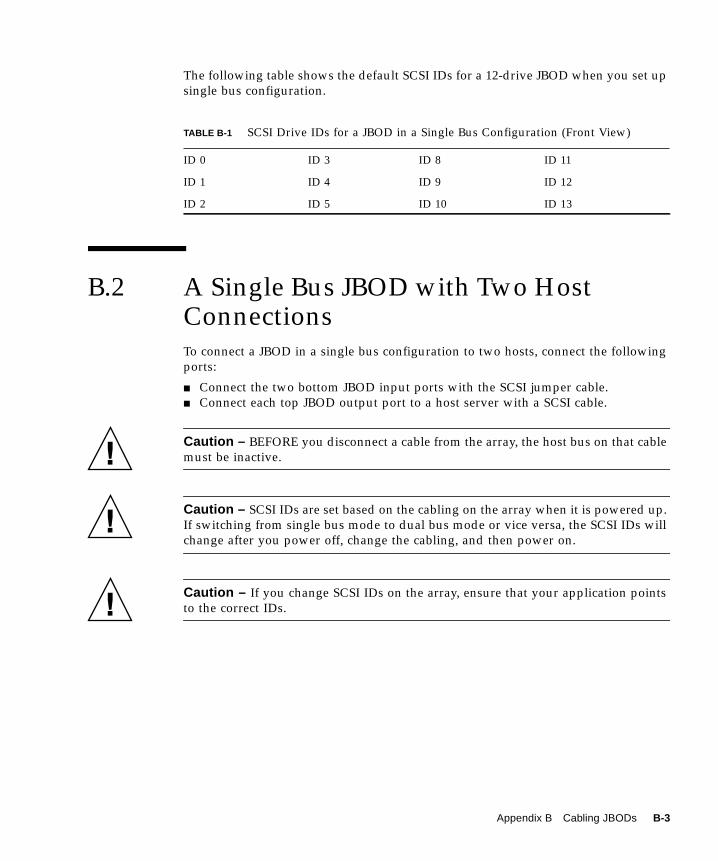
The following table shows the default SCSI IDs for a 12-drive JBOD when you set upsingle bus configuration.
B.2 A Single Bus JBOD with Two HostConnectionsTo connect a JBOD in a single bus configuration to two hosts, connect the followingports:
■ Connect the two bottom JBOD input ports with the SCSI jumper cable.■ Connect each top JBOD output port to a host server with a SCSI cable.
Caution – BEFORE you disconnect a cable from the array, the host bus on that cablemust be inactive.
Caution – SCSI IDs are set based on the cabling on the array when it is powered up.If switching from single bus mode to dual bus mode or vice versa, the SCSI IDs willchange after you power off, change the cabling, and then power on.
Caution – If you change SCSI IDs on the array, ensure that your application pointsto the correct IDs.
TABLE B-1 SCSI Drive IDs for a JBOD in a Single Bus Configuration (Front View)
ID 0 ID 3 ID 8 ID 11
ID 1 ID 4 ID 9 ID 12
ID 2 ID 5 ID 10 ID 13
Appendix B Cabling JBODs B-3
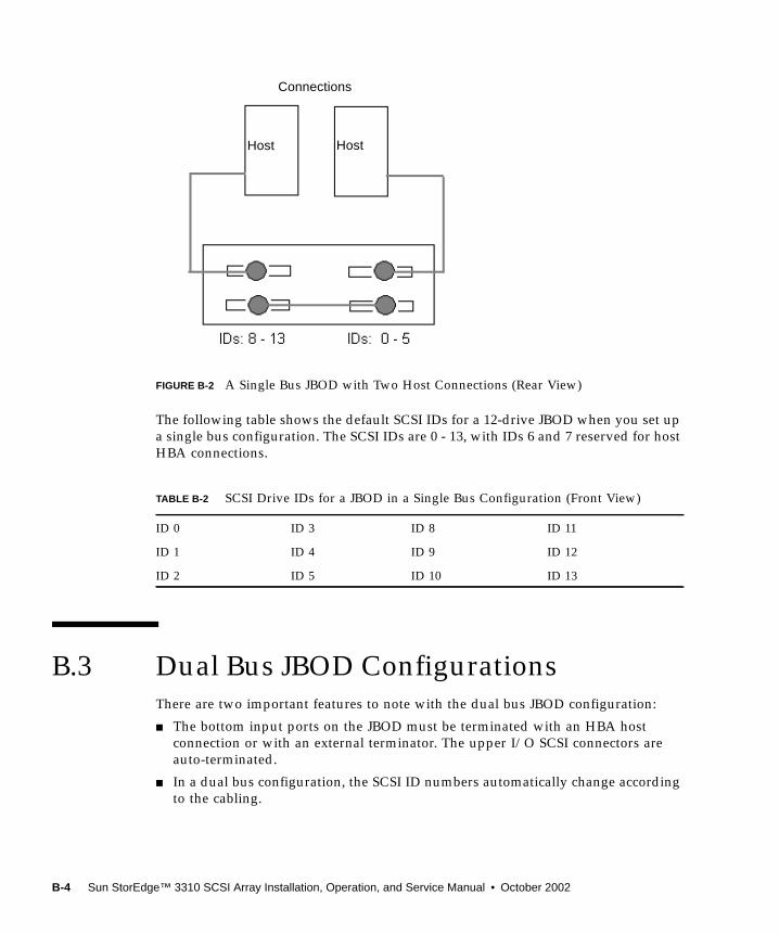
FIGURE B-2 A Single Bus JBOD with Two Host Connections (Rear View)
The following table shows the default SCSI IDs for a 12-drive JBOD when you set upa single bus configuration. The SCSI IDs are 0 - 13, with IDs 6 and 7 reserved for hostHBA connections.
B.3 Dual Bus JBOD ConfigurationsThere are two important features to note with the dual bus JBOD configuration:
■ The bottom input ports on the JBOD must be terminated with an HBA hostconnection or with an external terminator. The upper I/O SCSI connectors areauto-terminated.
■ In a dual bus configuration, the SCSI ID numbers automatically change accordingto the cabling.
TABLE B-2 SCSI Drive IDs for a JBOD in a Single Bus Configuration (Front View)
ID 0 ID 3 ID 8 ID 11
ID 1 ID 4 ID 9 ID 12
ID 2 ID 5 ID 10 ID 13
Host Host
Connections
B-4 Sun StorEdge™ 3310 SCSI Array Installation, Operation, and Service Manual • October 2002
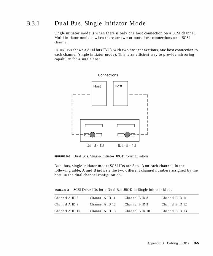
B.3.1 Dual Bus, Single Initiator ModeSingle initiator mode is when there is only one host connection on a SCSI channel.Multi-initiator mode is when there are two or more host connections on a SCSIchannel.
FIGURE B-3 shows a dual bus JBOD with two host connections, one host connection toeach channel (single initiator mode). This is an efficient way to provide mirroringcapability for a single host.
FIGURE B-3 Dual Bus, Single-Initiator JBOD Configuration
Dual bus, single initiator mode: SCSI IDs are 8 to 13 on each channel. In thefollowing table, A and B indicate the two different channel numbers assigned by thehost, in the dual channel configuration.
TABLE B-3 SCSI Drive IDs for a Dual Bus JBOD in Single Initiator Mode
Channel A ID 8 Channel A ID 11 Channel B ID 8 Channel B ID 11
Channel A ID 9 Channel A ID 12 Channel B ID 9 Channel B ID 12
Channel A ID 10 Channel A ID 13 Channel B ID 10 Channel B ID 13
Host Host
Connections
Appendix B Cabling JBODs B-5
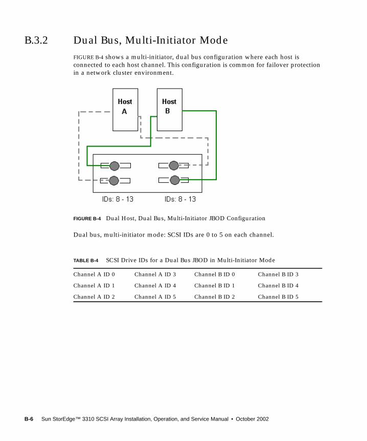
B.3.2 Dual Bus, Multi-Initiator ModeFIGURE B-4 shows a multi-initiator, dual bus configuration where each host isconnected to each host channel. This configuration is common for failover protectionin a network cluster environment.
FIGURE B-4 Dual Host, Dual Bus, Multi-Initiator JBOD Configuration
Dual bus, multi-initiator mode: SCSI IDs are 0 to 5 on each channel.
TABLE B-4 SCSI Drive IDs for a Dual Bus JBOD in Multi-Initiator Mode
Channel A ID 0 Channel A ID 3 Channel B ID 0 Channel B ID 3
Channel A ID 1 Channel A ID 4 Channel B ID 1 Channel B ID 4
Channel A ID 2 Channel A ID 5 Channel B ID 2 Channel B ID 5
B-6 Sun StorEdge™ 3310 SCSI Array Installation, Operation, and Service Manual • October 2002
To Connect a Dual Bus JBOD to Two Hosts
1. Connect each JBOD port to a host as shown in FIGURE B-4.
2. Make inactive the host bus connections of any cable which will be installed orremoved.
Caution – The bottom input ports of the JBOD must have a host connection orexternal terminator to maintain SCSI bus integrity.
Caution – BEFORE you disconnect a cable from the array, the host bus on that cablemust be inactive.
Caution – SCSI IDs are set based on the cabling on the array when it is powered up.If switching from single bus mode to dual bus mode or vice versa, the SCSI IDs willchange after you power off, change the cabling, and then power on.
Caution – If you change SCSI IDs on the array, ensure that your application pointsto the correct IDs.
Note – The Sun SCSI LVD/MSE external terminator is part number XTA-3310-SC-TERM (595-6750-01).
Appendix B Cabling JBODs B-7

B-8 Sun StorEdge™ 3310 SCSI Array Installation, Operation, and Service Manual • October 2002
APPENDIX C
Ethernet Connection
This appendix provides Ethernet connection information. Topics covered are:
■ “Setting an IP Address” on page C-1
■ “Setting Up Out-of-Band Management Over Ethernet” on page C-3
C.1 Setting an IP AddressTo set the IP address of the RAID controller, perform the following steps.
1. Access the Sun StorEdge RAID controller via a RAID Array COM port.
2. On the Main Menu, select “view and edit Configuration parameters.”
3. Select “Communication Parameters”, and then select “Internet Protocol (TCP/IP).”
4. Press Return on the chip hardware address, and then select “Set IP Address.”
5. Type the desired IP address, netmask, and Gateway values.
C-1
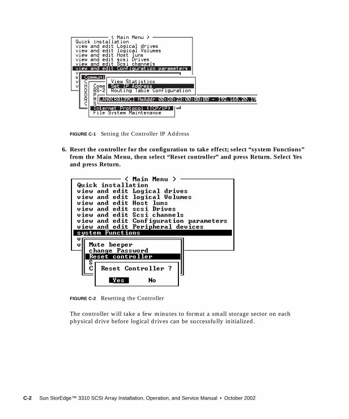
FIGURE C-1 Setting the Controller IP Address
6. Reset the controller for the configuration to take effect; select “system Functions”from the Main Menu, then select “Reset controller” and press Return. Select Yesand press Return.
FIGURE C-2 Resetting the Controller
The controller will take a few minutes to format a small storage sector on eachphysical drive before logical drives can be successfully initialized.
C-2 Sun StorEdge™ 3310 SCSI Array Installation, Operation, and Service Manual • October 2002
C.2 Setting Up Out-of-Band ManagementOver Ethernet
1. To access the RAID Array over an Ethernet connection, first set the IP address ofthe RAID Array by using the RAID Array COM port and the RAID firmware(refer to “Setting an IP Address” on page C-1).
2. Then connect the RAID Array Ethernet port to the network.
3. To connect to the firmware application program (used in this manual) from thehost server, tenet directly to the IP address of the RAID array controller with thefollowing command:
Press Cntrl-l (letter el) to refresh the screen and view the Main Menu.
Note – If you reset the controller during a telnet session, you will be disconnectedfrom the RAID array and will need to telnet back into the array.
4. To connect the Configuration Service program (on a host server) to a RAID arraywhich has an IP address, refer to the out-of-band management instructions in theSun StorEdge 3310 Configuration Service User Guide.
In the following network illustration, there are two servers which receiveConfiguration Service Alert messages, and a Configuration Service managementconsole which monitors and configures the RAID array as needed.
# telnet <IP address>
Appendix C Ethernet Connection C-3
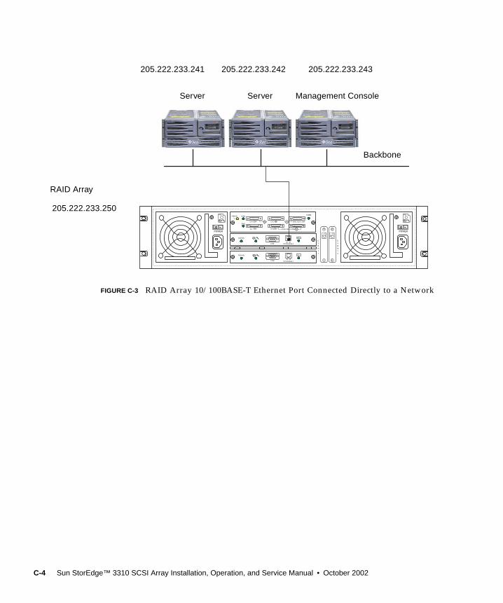
FIGURE C-3 RAID Array 10/100BASE-T Ethernet Port Connected Directly to a Network
POWER
COM 10/100 BASE-T
ERROR TERM
SNGLCH 0
CH 1
CH 3
CH 2
SNGL BUS CONF
DUAL BUS CONF
TERM
DB
SB SB
EVENT 1
EVENT 2
POWER
Activity
< >...+
COM 10/100 BASE-T
Activity
< >...+
PS PS
EMUEMU
RAID Array
205.222.233.250
205.222.233.242 205.222.233.243
Server
205.222.233.241
Server Management Console
Backbone
C-4 Sun StorEdge™ 3310 SCSI Array Installation, Operation, and Service Manual • October 2002
APPENDIX D
Record of Settings
This appendix provides tables for recording configuration data. Topics covered are:
■ “View and Edit Logical Drives” on page D-2
■ “Logical Drive Information” on page D-2
■ “Logical Drive Partition Information” on page D-3
■ “View and Edit Host LUNs” on page D-4
■ “LUN Mappings” on page D-4
■ “View and Edit SCSI Drives” on page D-5
■ “View and Edit SCSI Channels” on page D-6
■ “View and Edit Peripheral Devices” on page D-8
■ “Save NVRAM to Disk, Restore from Disk” on page D-8
In addition to saving the configuration data in NVRAM to disk, keeping a hard copyof the controller configuration is also recommended. This will speed the recreation ofthe RAID in the event of a disaster.
The following tables are provided as a model for recording configuration data.
As a general rule, the configuration data in the NVRAM should be saved to disk or filewhenever a configuration change is made.
D-1
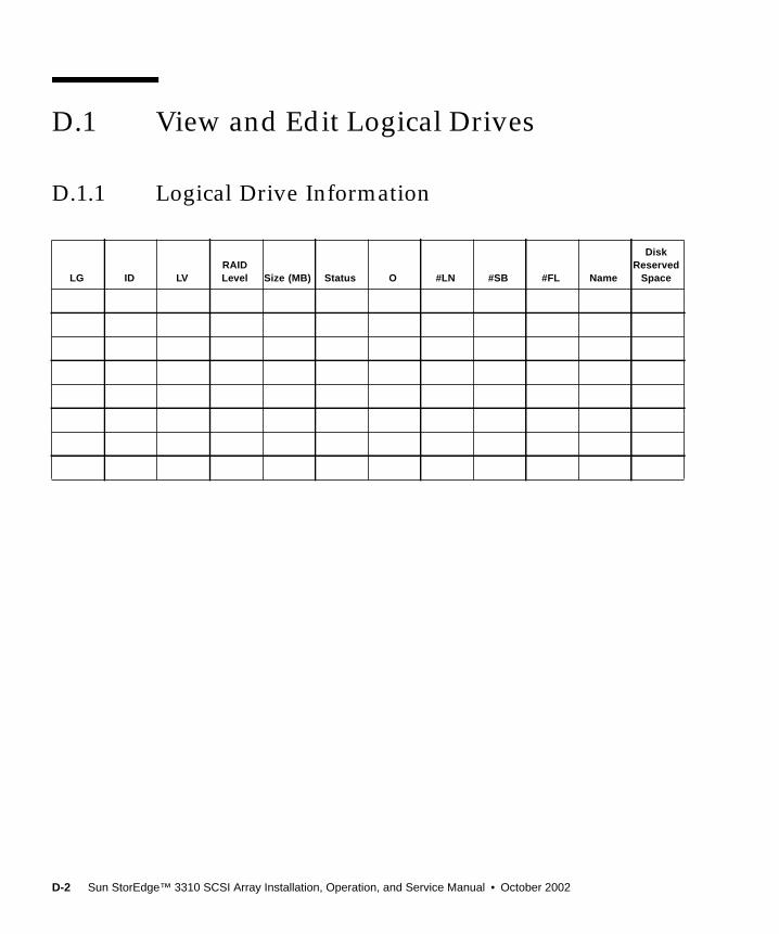
D.1 View and Edit Logical Drives
D.1.1 Logical Drive Information
LG ID LVRAIDLevel Size (MB) Status O #LN #SB #FL Name
DiskReserved
Space
D-2 Sun StorEdge™ 3310 SCSI Array Installation, Operation, and Service Manual • October 2002

D.1.2 Logical Drive Partition Information
LG Partition Size (MB) LG Partition Size (MB)
Appendix D Record of Settings D-3

D.2 View and Edit Host LUNs
D.2.1 LUN Mappings
Host ChannelPri. / Sec.Controller SCSI ID LUN
Logical Drive /Logical Volume Partition Size
D-4 Sun StorEdge™ 3310 SCSI Array Installation, Operation, and Service Manual • October 2002
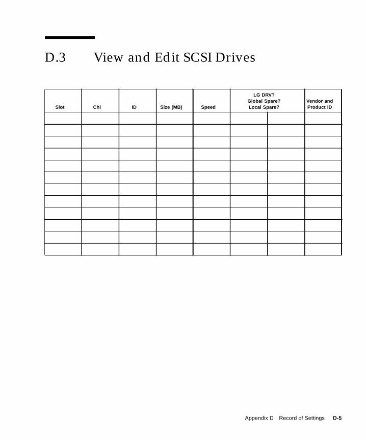
D.3 View and Edit SCSI Drives
Slot Chl ID Size (MB) Speed
LG DRV?Global Spare?Local Spare?
Vendor andProduct ID
Appendix D Record of Settings D-5

D.4 View and Edit SCSI Channels
Slot Chl ID Size (MB) Speed
LG DRV?Global Spare?Local Spare?
Vendor andProduct ID
Chl Mode (Host / Drive)Primary Controller SCSI
ID(s)Secondary Controller SCSI
ID(s)
D-6 Sun StorEdge™ 3310 SCSI Array Installation, Operation, and Service Manual • October 2002
Appendix D Record of Settings D-7
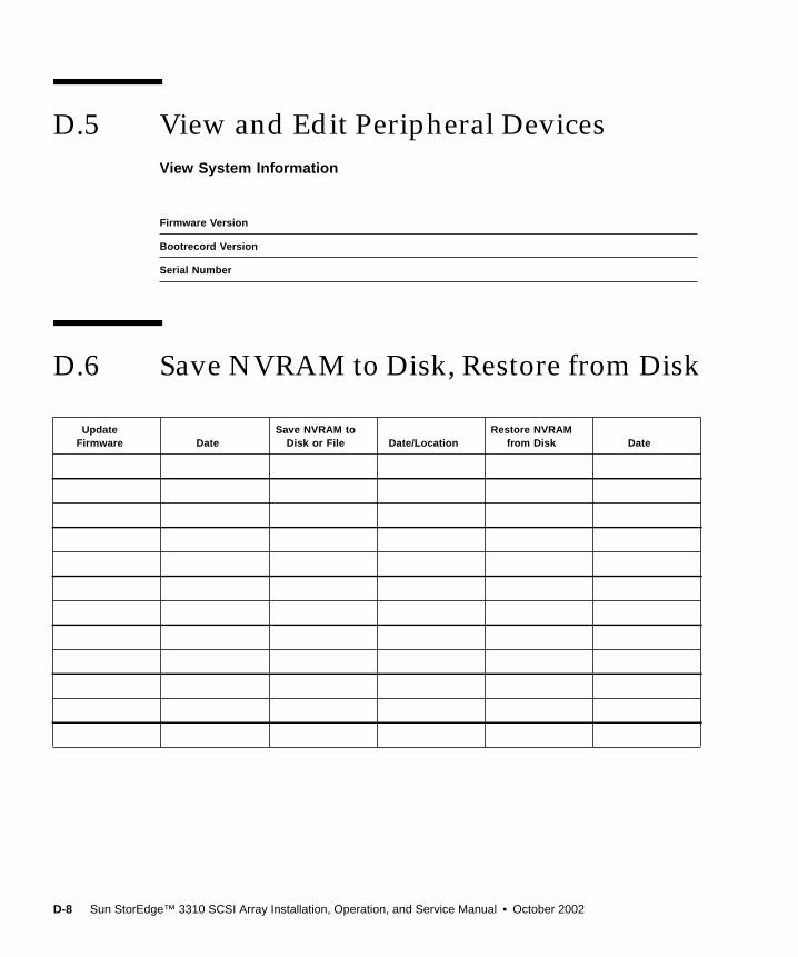
D.5 View and Edit Peripheral DevicesView System Information
D.6 Save NVRAM to Disk, Restore from Disk
Firmware Version
Bootrecord Version
Serial Number
UpdateFirmware Date
Save NVRAM toDisk or File Date/Location
Restore NVRAMfrom Disk Date
D-8 Sun StorEdge™ 3310 SCSI Array Installation, Operation, and Service Manual • October 2002

APPENDIX E
Solaris sd.conf Setup and VolumeLabels
This appendix provides an example sd.conf file that specifies available host LUNassignments. By default, a Solaris host has only one host LUN per target ID, whichtypically is not enough LUNs for a Sun StorEdge array.
For your convenience, the procedure on how to label a Solaris volume is alsoprovided.
E.1 Editing the sd.conf FileEdit the /kernel/drv/sd.conf file to add additional targets and LUNs, up to128 LUNs which can be used in a single Sun StorEdge array. Then reboot the host.
You may want to allow a few extra LUNs for flexibility over the coming months, butgenerally most administrators minimize the number of unused LUNs because eachLUN causes a seven-second delay when you reboot the host.
Note – The maximum number of LUNs per target is 32.
Caution – After you edit sd.conf, you must reboot the host to enable the newLUN assignments.
E-1
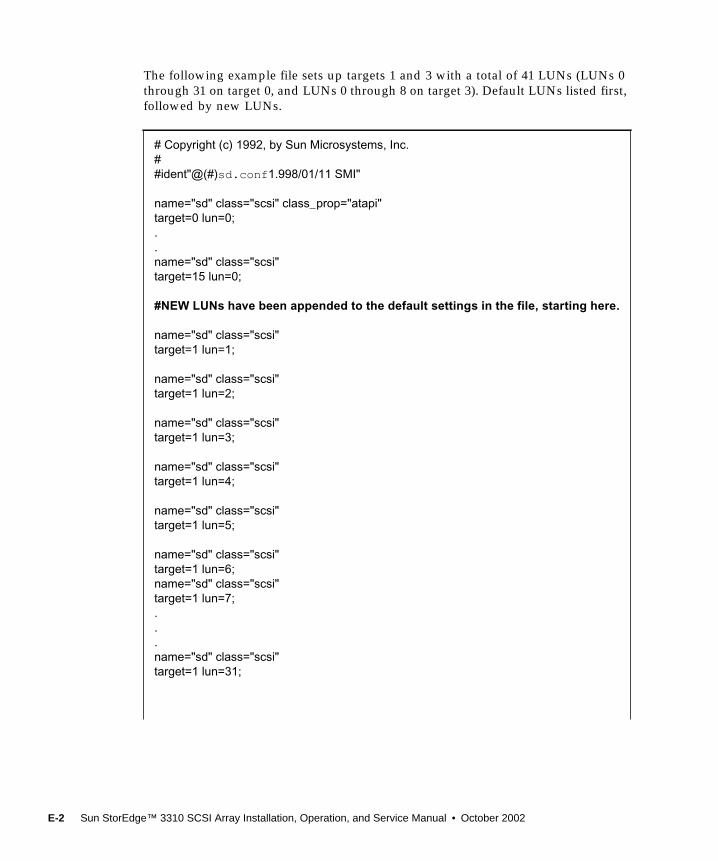
The following example file sets up targets 1 and 3 with a total of 41 LUNs (LUNs 0through 31 on target 0, and LUNs 0 through 8 on target 3). Default LUNs listed first,followed by new LUNs.
# Copyright (c) 1992, by Sun Microsystems, Inc.##ident"@(#)sd.conf1.998/01/11 SMI"
name="sd" class="scsi" class_prop="atapi"target=0 lun=0;..name="sd" class="scsi"target=15 lun=0;
#NEW LUNs have been appended to the default settings in the file, starting here.
name="sd" class="scsi"target=1 lun=1;
name="sd" class="scsi"target=1 lun=2;
name="sd" class="scsi"target=1 lun=3;
name="sd" class="scsi"target=1 lun=4;
name="sd" class="scsi"target=1 lun=5;
name="sd" class="scsi"target=1 lun=6;name="sd" class="scsi"target=1 lun=7;...name="sd" class="scsi"target=1 lun=31;
E-2 Sun StorEdge™ 3310 SCSI Array Installation, Operation, and Service Manual • October 2002
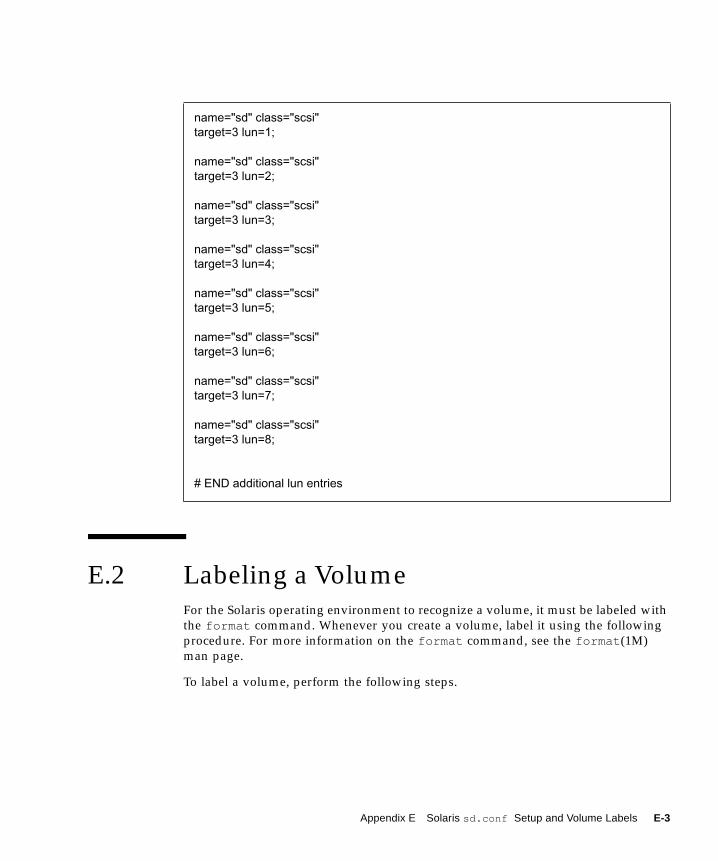
E.2 Labeling a VolumeFor the Solaris operating environment to recognize a volume, it must be labeled withthe format command. Whenever you create a volume, label it using the followingprocedure. For more information on the format command, see the format(1M)man page.
To label a volume, perform the following steps.
name="sd" class="scsi"target=3 lun=1;
name="sd" class="scsi"target=3 lun=2;
name="sd" class="scsi"target=3 lun=3;
name="sd" class="scsi"target=3 lun=4;
name="sd" class="scsi"target=3 lun=5;
name="sd" class="scsi"target=3 lun=6;
name="sd" class="scsi"target=3 lun=7;
name="sd" class="scsi"target=3 lun=8;
# END additional lun entries
Appendix E Solaris sd.conf Setup and Volume Labels E-3
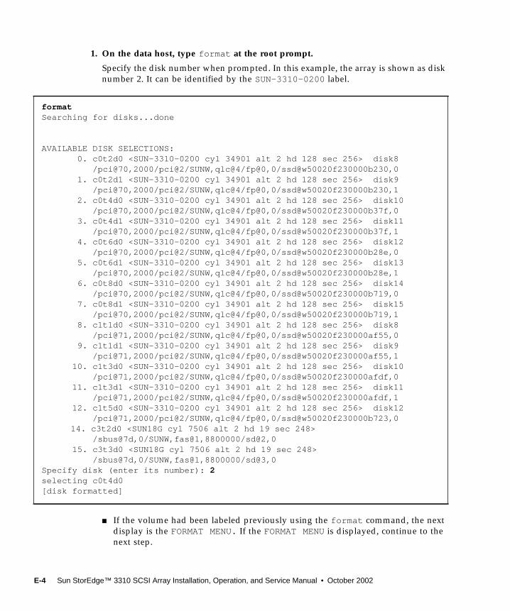
1. On the data host, type format at the root prompt.
Specify the disk number when prompted. In this example, the array is shown as disknumber 2. It can be identified by the SUN-3310-0200 label.
■ If the volume had been labeled previously using the format command, the nextdisplay is the FORMAT MENU. If the FORMAT MENU is displayed, continue to thenext step.
formatSearching for disks...done
AVAILABLE DISK SELECTIONS: 0. c0t2d0 <SUN-3310-0200 cyl 34901 alt 2 hd 128 sec 256> disk8 /pci@70,2000/pci@2/SUNW,qlc@4/fp@0,0/ssd@w50020f230000b230,0 1. c0t2d1 <SUN-3310-0200 cyl 34901 alt 2 hd 128 sec 256> disk9 /pci@70,2000/pci@2/SUNW,qlc@4/fp@0,0/ssd@w50020f230000b230,1 2. c0t4d0 <SUN-3310-0200 cyl 34901 alt 2 hd 128 sec 256> disk10 /pci@70,2000/pci@2/SUNW,qlc@4/fp@0,0/ssd@w50020f230000b37f,0 3. c0t4d1 <SUN-3310-0200 cyl 34901 alt 2 hd 128 sec 256> disk11 /pci@70,2000/pci@2/SUNW,qlc@4/fp@0,0/ssd@w50020f230000b37f,1 4. c0t6d0 <SUN-3310-0200 cyl 34901 alt 2 hd 128 sec 256> disk12 /pci@70,2000/pci@2/SUNW,qlc@4/fp@0,0/ssd@w50020f230000b28e,0 5. c0t6d1 <SUN-3310-0200 cyl 34901 alt 2 hd 128 sec 256> disk13 /pci@70,2000/pci@2/SUNW,qlc@4/fp@0,0/ssd@w50020f230000b28e,1 6. c0t8d0 <SUN-3310-0200 cyl 34901 alt 2 hd 128 sec 256> disk14 /pci@70,2000/pci@2/SUNW,qlc@4/fp@0,0/ssd@w50020f230000b719,0 7. c0t8d1 <SUN-3310-0200 cyl 34901 alt 2 hd 128 sec 256> disk15 /pci@70,2000/pci@2/SUNW,qlc@4/fp@0,0/ssd@w50020f230000b719,1 8. c1t1d0 <SUN-3310-0200 cyl 34901 alt 2 hd 128 sec 256> disk8 /pci@71,2000/pci@2/SUNW,qlc@4/fp@0,0/ssd@w50020f230000af55,0 9. c1t1d1 <SUN-3310-0200 cyl 34901 alt 2 hd 128 sec 256> disk9 /pci@71,2000/pci@2/SUNW,qlc@4/fp@0,0/ssd@w50020f230000af55,1 10. c1t3d0 <SUN-3310-0200 cyl 34901 alt 2 hd 128 sec 256> disk10 /pci@71,2000/pci@2/SUNW,qlc@4/fp@0,0/ssd@w50020f230000afdf,0 11. c1t3d1 <SUN-3310-0200 cyl 34901 alt 2 hd 128 sec 256> disk11 /pci@71,2000/pci@2/SUNW,qlc@4/fp@0,0/ssd@w50020f230000afdf,1 12. c1t5d0 <SUN-3310-0200 cyl 34901 alt 2 hd 128 sec 256> disk12 /pci@71,2000/pci@2/SUNW,qlc@4/fp@0,0/ssd@w50020f230000b723,0
14. c3t2d0 <SUN18G cyl 7506 alt 2 hd 19 sec 248> /sbus@7d,0/SUNW,fas@1,8800000/sd@2,0 15. c3t3d0 <SUN18G cyl 7506 alt 2 hd 19 sec 248> /sbus@7d,0/SUNW,fas@1,8800000/sd@3,0Specify disk (enter its number): 2selecting c0t4d0[disk formatted]
E-4 Sun StorEdge™ 3310 SCSI Array Installation, Operation, and Service Manual • October 2002
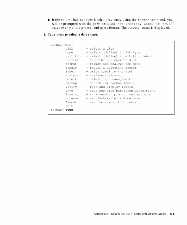
■ If the volume had not been labeled previously using the format command, youwill be prompted with the question: Disk not labeled. Label it now? Ifso, answer y at the prompt and press Return. The FORMAT MENU is displayed.
2. Type type to select a drive type.
FORMAT MENU: disk - select a disk type - select (define) a disk type partition - select (define) a partition table current - describe the current disk format - format and analyze the disk repair - repair a defective sector label - write label to the disk analyze - surface analysis defect - defect list management backup - search for backup labels verify - read and display labels save - save new disk/partition definitions inquiry - show vendor, product and revision volname - set 8-character volume name !<cmd> - execute <cmd>, then return0 quitformat> type
Appendix E Solaris sd.conf Setup and Volume Labels E-5
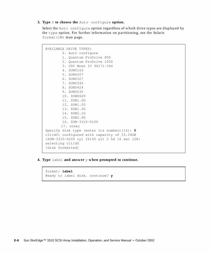
3. Type 0 to choose the Auto configure option.
Select the Auto configure option regardless of which drive types are displayed bythe type option. For further information on partitioning, see the Solarisformat(1M) man page.
4. Type label and answer y when prompted to continue.
AVAILABLE DRIVE TYPES: 0. Auto configure 1. Quantum ProDrive 80S 2. Quantum ProDrive 105S 3. CDC Wren IV 94171-344 4. SUN0104 5. SUN0207 6. SUN0327 7. SUN0340 8. SUN0424 9. SUN0535 10. SUN0669 11. SUN1.0G 12. SUN1.05 13. SUN1.3G 14. SUN2.1G 15. SUN2.9G 16. SUN-3310-0100
17. otherSpecify disk type (enter its number)[16]: 0c1t1d0: configured with capacity of 33.34GB<SUN-3310-0200 cyl 34145 alt 2 hd 16 sec 128>selecting c1t1d0[disk formatted]
format> labelReady to label disk, continue? y
E-6 Sun StorEdge™ 3310 SCSI Array Installation, Operation, and Service Manual • October 2002
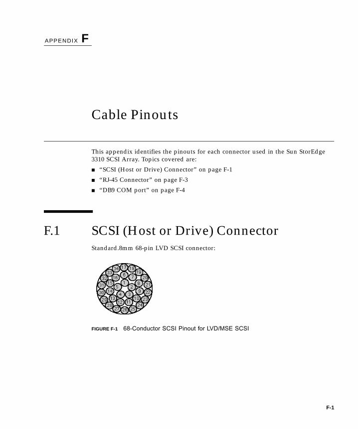
APPENDIX F
Cable Pinouts
This appendix identifies the pinouts for each connector used in the Sun StorEdge3310 SCSI Array. Topics covered are:
■ “SCSI (Host or Drive) Connector” on page F-1
■ “RJ-45 Connector” on page F-3
■ “DB9 COM port” on page F-4
F.1 SCSI (Host or Drive) ConnectorStandard.8mm 68-pin LVD SCSI connector:
FIGURE F-1 68-Conductor SCSI Pinout for LVD/MSE SCSI
F-1
*SR=Signal Return, *RSVD=Reserved, *GND=Ground, *TPWR=TERMPWR
TABLE F-1 SCSI Connector Pin Numbers and Cable Pairs
PIN# CABLE SE/LVDPAIR
PIN# CABLE SE/LVDPAIR
1 30SR/+DB122 31SR/+DB133 32SR/+DB144 33SR/+DB155 34SR/+DBP16 16SR/+DB07 17SR/+DB18 18SR/+DB29 19SR/+DB310 20SR/+DB411 21SR/+DB512 22SR/+DB613 23SR/+DB714 24SR/+P_CRCA15 25GND/GND16 15DIFFSENSE17 14TPWR/TPWR18 13TPWR/TPWR19 12RSVD/RSVD20 5GND/GND21 6SR/+ATN22 7GND/GND23 4SR/+BSY24 3SR/+ACK25 8SR/+RST26 9SR/+MSG27 10SR/+SEL28 2SR/+C/D29 1SR/+REQ30 11SR/+I/031 26SR/+DB832 27SR/+DB933 28SR/+DB1034 29SR/+DB11
35 30-DB12/-DB1236 31-DB13/-DB1337 32-DB14/-DB1438 33-DB15/-DB1539 34-DBP1/-DBP140 16-DB0/-DB041 17-DB1/-DB142 18-DB2/-DB243 19-DB3/-DB344 20-DB4/-DB445 21-DB5/-DB546 22-DB6/-DB647 23-DB7/-DB748 24-DBP/-P_CRCA49 25GND/GND50 15GND/GND51 14TPWR/TPWR52 13TPWR/TPWR53 12RSVD/RSVD54 5GND/GND55 6-ATN/-ATN56 7GND/GND57 4-BSY/-BSY58 3-ACK/-ACK59 8-RST/-RST60 9-MSG/-MSG61 10-SEL/-SEL62 2-C/D/-C/D63 1-REQ/-REQ64 11-I/O/-I/O65 26-DB8/-DB866 27-DB9/-DB967 28-DB10/-DB1068 29-DB11/-DB11
F-2 Sun StorEdge™ 3310 SCSI Array Installation, Operation, and Service Manual • October 2002
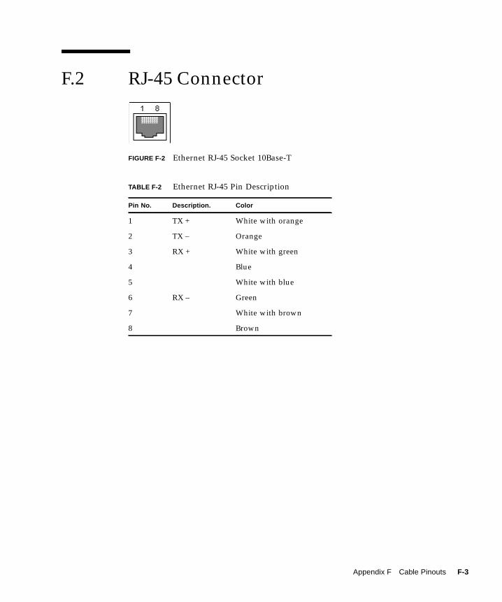
F.2 RJ-45 Connector
FIGURE F-2 Ethernet RJ-45 Socket 10Base-T
TABLE F-2 Ethernet RJ-45 Pin Description
Pin No. Description. Color
1 TX + White with orange
2 TX – Orange
3 RX + White with green
4 Blue
5 White with blue
6 RX – Green
7 White with brown
8 Brown
Appendix F Cable Pinouts F-3
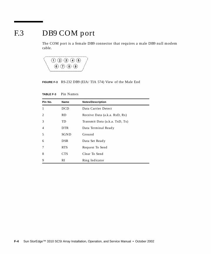
F.3 DB9 COM portThe COM port is a female DB9 connector that requires a male DB9 null modemcable.
FIGURE F-3 RS-232 DB9 (EIA/TIA 574) View of the Male End
TABLE F-3 Pin Names
Pin No. Name Notes/Description
1 DCD Data Carrier Detect
2 RD Receive Data (a.k.a. RxD, Rx)
3 TD Transmit Data (a.k.a. TxD, Tx)
4 DTR Data Terminal Ready
5 SGND Ground
6 DSR Data Set Ready
7 RTS Request To Send
8 CTS Clear To Send
9 RI Ring Indicator
B9 (EIA/TIA 574) Vi
F-4 Sun StorEdge™ 3310 SCSI Array Installation, Operation, and Service Manual • October 2002
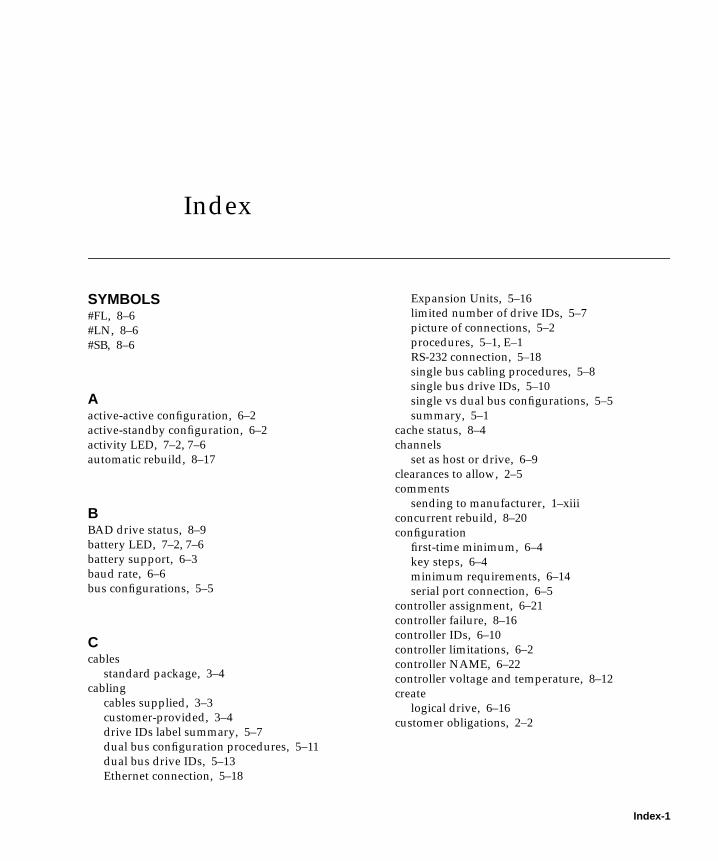
Index
SYMBOLS#FL, 8–6#LN, 8–6#SB, 8–6
Aactive-active configuration, 6–2active-standby configuration, 6–2activity LED, 7–2, 7–6automatic rebuild, 8–17
BBAD drive status, 8–9battery LED, 7–2, 7–6battery support, 6–3baud rate, 6–6bus configurations, 5–5
Ccables
standard package, 3–4cabling
cables supplied, 3–3customer-provided, 3–4drive IDs label summary, 5–7dual bus configuration procedures, 5–11dual bus drive IDs, 5–13Ethernet connection, 5–18
Expansion Units, 5–16limited number of drive IDs, 5–7picture of connections, 5–2procedures, 5–1, E–1RS-232 connection, 5–18single bus cabling procedures, 5–8single bus drive IDs, 5–10single vs dual bus configurations, 5–5summary, 5–1
cache status, 8–4channels
set as host or drive, 6–9clearances to allow, 2–5comments
sending to manufacturer, 1–xiiiconcurrent rebuild, 8–20configuration
first-time minimum, 6–4key steps, 6–4minimum requirements, 6–14serial port connection, 6–5
controller assignment, 6–21controller failure, 8–16controller IDs, 6–10controller limitations, 6–2controller NAME, 6–22controller voltage and temperature, 8–12create
logical drive, 6–16customer obligations, 2–2
Index-1
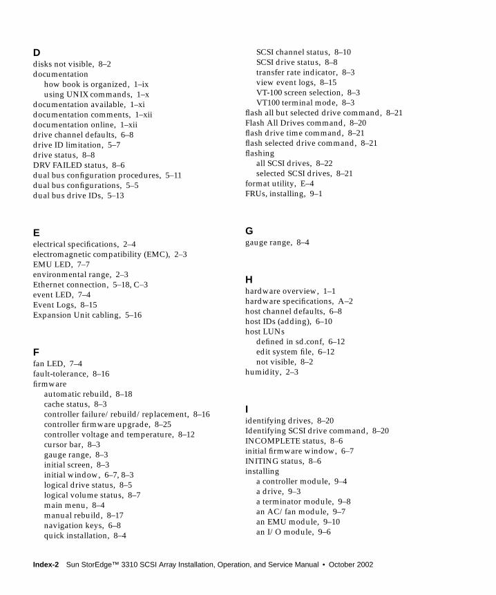
Ddisks not visible, 8–2documentation
how book is organized, 1–ixusing UNIX commands, 1–x
documentation available, 1–xidocumentation comments, 1–xiidocumentation online, 1–xiidrive channel defaults, 6–8drive ID limitation, 5–7drive status, 8–8DRV FAILED status, 8–6dual bus configuration procedures, 5–11dual bus configurations, 5–5dual bus drive IDs, 5–13
Eelectrical specifications, 2–4electromagnetic compatibility (EMC), 2–3EMU LED, 7–7environmental range, 2–3Ethernet connection, 5–18, C–3event LED, 7–4Event Logs, 8–15Expansion Unit cabling, 5–16
Ffan LED, 7–4fault-tolerance, 8–16firmware
automatic rebuild, 8–18cache status, 8–3controller failure/rebuild/replacement, 8–16controller firmware upgrade, 8–25controller voltage and temperature, 8–12cursor bar, 8–3gauge range, 8–3initial screen, 8–3initial window, 6–7, 8–3logical drive status, 8–5logical volume status, 8–7main menu, 8–4manual rebuild, 8–17navigation keys, 6–8quick installation, 8–4
SCSI channel status, 8–10SCSI drive status, 8–8transfer rate indicator, 8–3view event logs, 8–15VT-100 screen selection, 8–3VT100 terminal mode, 8–3
flash all but selected drive command, 8–21Flash All Drives command, 8–20flash drive time command, 8–21flash selected drive command, 8–21flashing
all SCSI drives, 8–22selected SCSI drives, 8–21
format utility, E–4FRUs, installing, 9–1
Ggauge range, 8–4
Hhardware overview, 1–1hardware specifications, A–2host channel defaults, 6–8host IDs (adding), 6–10host LUNs
defined in sd.conf, 6–12edit system file, 6–12not visible, 8–2
humidity, 2–3
Iidentifying drives, 8–20Identifying SCSI drive command, 8–20INCOMPLETE status, 8–6initial firmware window, 6–7INITING status, 8–6installing
a controller module, 9–4a drive, 9–3a terminator module, 9–8an AC/fan module, 9–7an EMU module, 9–10an I/O module, 9–6
Index-2 Sun StorEdge™ 3310 SCSI Array Installation, Operation, and Service Manual • October 2002
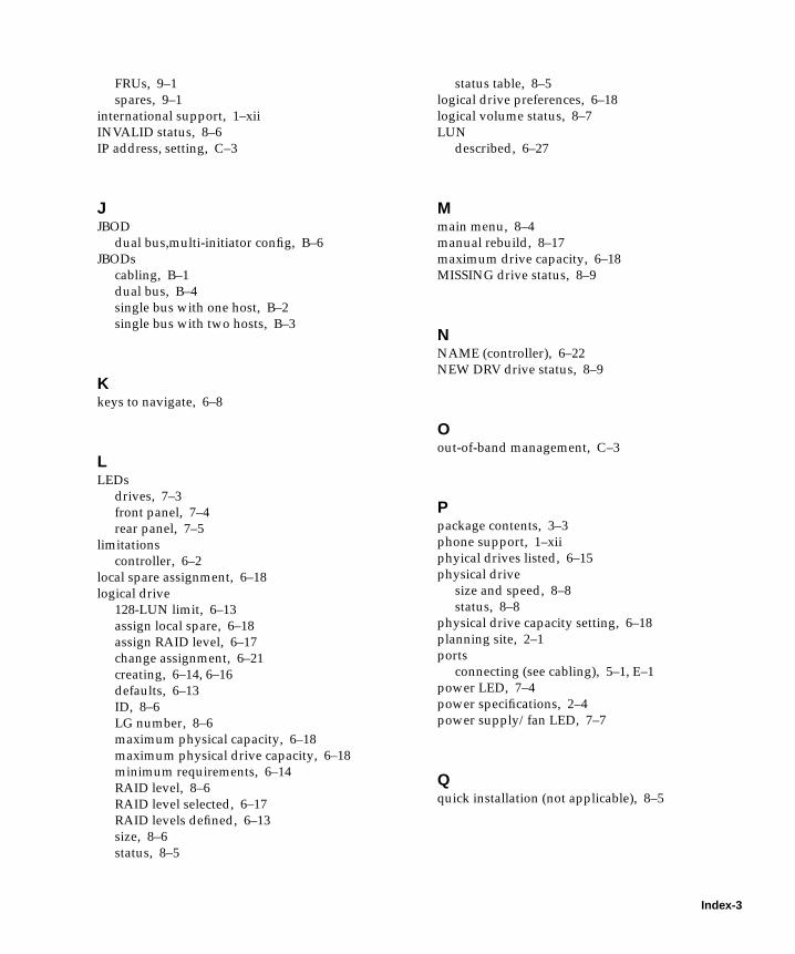
FRUs, 9–1spares, 9–1
international support, 1–xiiINVALID status, 8–6IP address, setting, C–3
JJBOD
dual bus,multi-initiator config, B–6JBODs
cabling, B–1dual bus, B–4single bus with one host, B–2single bus with two hosts, B–3
Kkeys to navigate, 6–8
LLEDs
drives, 7–3front panel, 7–4rear panel, 7–5
limitationscontroller, 6–2
local spare assignment, 6–18logical drive
128-LUN limit, 6–13assign local spare, 6–18assign RAID level, 6–17change assignment, 6–21creating, 6–14, 6–16defaults, 6–13ID, 8–6LG number, 8–6maximum physical capacity, 6–18maximum physical drive capacity, 6–18minimum requirements, 6–14RAID level, 8–6RAID level selected, 6–17RAID levels defined, 6–13size, 8–6status, 8–5
status table, 8–5logical drive preferences, 6–18logical volume status, 8–7LUN
described, 6–27
Mmain menu, 8–4manual rebuild, 8–17maximum drive capacity, 6–18MISSING drive status, 8–9
NNAME (controller), 6–22NEW DRV drive status, 8–9
Oout-of-band management, C–3
Ppackage contents, 3–3phone support, 1–xiiphyical drives listed, 6–15physical drive
size and speed, 8–8status, 8–8
physical drive capacity setting, 6–18planning site, 2–1ports
connecting (see cabling), 5–1, E–1power LED, 7–4power specifications, 2–4power supply/fan LED, 7–7
Qquick installation (not applicable), 8–5
Index-3
Rrackmounting
cabinet mount, 4–3site preparation, 4–2telco center-of-gravity mount, 4–13telco flushmount, 4–10telco mount, 4–9tools required, 4–2, 4–3
RAID (0+1)concurrent rebuild in, 8–20
RAID level assignment, 6–17RAID levels
defined, 6–13selected, 6–17
RAID levels defined, 6–13rebuild
automatic, 8–17concurrent in RAID (0+1), 8–20manual, 8–17
reconfiguring a volumelabeling, E–3
redundant controllerexplained, 8–16
remote file, 6–6replacing parts (see also "installing"), 9–1, 9–6reset controller
controller reset, 6–22RS-232
connecting to, 5–18, 6–5upgrading firmware via, 8–26
Ssafety precautions, 2–2SB-MISS drive status, 8–9SCSI channel status, 8–10SCSI channels
default channels, 6–8host or drive, 6–8
SCSI driveglobal or local spare, 8–9STANDBY mode, 8–9USED DRV mode, 8–9vendor ID, 8–9
SCSI drive status, 8–8SCSI host IDs (creating), 6–10sd.conf for device files, 6–12sending documentation comments, 1–xiii
serial port connection, 6–5serial port parameters, 6–5settings records to keep, D–1single bus cabling procedures, 5–8single bus configurations, 5–5single bus drive IDs, 5–10site planning, 2–1
console requirement, 2–7customer obligations, 2–2electrical/power, 2–4EMC, 2–3environmental, 2–3layout, 2–5physical, 2–5safety precautions, 2–2
site preparation survey, 2–7size of drive, 8–8Solaris
edit sd.conf, 6–12edit system file, 6–12reset baud rate, 6–6
spare (local for logical drive), 6–18spare drives, 8–20spares, installing, 9–1specifications
clearances, 2–5electrical/power, 2–4physical (array), 2–5
specifications (product), A–2speed of drive, 8–8STAND-BY drive status, 8–9status LED, 4–17, 7–2, 7–6system file edit, 6–12
Ttechnical support, 1–xiitemp LED, 7–4temperature
environmental range, 2–3temperature LED, 7–4tip command, 6–6transfer rate indicator, 8–4troubleshooting
disks not visible, 8–2LUNs not visible, 8–2
troubleshooting support, 1–xii
Index-4 Sun StorEdge™ 3310 SCSI Array Installation, Operation, and Service Manual • October 2002
UUSED DRV drive status, 8–9
Vview
connected drives, 6–15volume
reconfiguringlabeling, E–3
VT100 terminal connection, 5–18VT100 terminal mode, 8–3
Index-5

Index-6 Sun StorEdge™ 3310 SCSI Array Installation, Operation, and Service Manual • October 2002