svs-650 color lcd echo sounder - si-tex.com · si-tex svs-650 2 svs-650 fish finder system caution...
TRANSCRIPT

SI-TEX SVS-650
1
SVS-650 Color LCD Echo Sounder
Revised March 2012
Operation & Installation Manual

SI-TEX SVS-650
2
SVS-650 Fish finder System
CAUTION
The SVS-650 Color LCD Echo sounder Systems employs the latest in proven technology to provide
accurate fish & bottom information. The navigation functions of SVS-650 are totally dependent
upon the capability of the navigation source to provide accurate position information. This
device is only an aid to navigation. It should not be used to replace other sources of navigation
information.
CAUTION
The performance of LCD displays is degraded by continuous direct exposure to high
temperatures. When not in use, covering the display with the included plastic sun cover will
help extend the service life of the display.

SI-TEX SVS-650
3
Welcome
Thank you for purchasing the SI-TEX SVS-650
The SVS-650 is a premium multifunction Fish Finder System. SVS-650 front panel keyboard and
its wide screen viewing area make placement easy. Although SVS-650 offers many advanced
features, operation is simplified through the use of popup menus similar to those found on
personal computers. The SI-TEX SVS-650 Color LCD Fish finder System opens a new chapter
of performance and integration in Fish finder system display and management. Whether you are
a Cruiser or Sport fisherman or both, SVS-650 gives you the information you need.
Features of the SVS-650
Comprised of a display unit and a dual frequency transducer.
The main features of the SVS-650 are:
▶ A large 6.5” Direct Sunlight Viewable High Definition LCD Display, in a vertical format to
provide maximum sonar resolution! 750x450 pixels.
▶ Fish finder offer’s Superior fish detection and bottom discrimination using the new SI-TEX
Digital Sounder System.
▶ Adapts to changing seabed and water conditions providing fully automatic “hands free”
operation.
▶ A Powerful best in class 600 watt dual frequency 50/200Khz transceiver.
▶ Digital technology eliminates unwanted noise and provides the clearest images possible at
all times.
▶ Multiple Display Modes: Normal (Single or Dual Freq.), Bottom Zoom, Bottom Lock, Shift,
Split Screens, GPS Position, Waypoint Steering, Navigation Highway.
▶ Auto & Manual Range & Gain Controls, Each Frequency can be independently controlled!
Also, Auto & Manual Shift.

SI-TEX SVS-650
4
Features of the SVS-650 (continued)
▶ 10 Page Screen Capture Memory allows you to take Snap Shots of the Fish Finder Screen
and save them to memory.
▶ 10 Event point memory allows you to instantly save a Fishing location and compute your
course steering info back to the spot.
▶ Waterproof to IPX7 International Standard
▶ Very easy to operate, with front panel knobs for Gain and STC, Simple Menu Format, and all
controls labeled in plain English.
▶ New White Line / Black Line Bottom Discriminator .
▶ Fish Symbols
▶ Depth Alarm, Sea Temperature Alarm, Fish Alarm
▶ Standard equipment includes Snap on Sun Cover.

SI-TEX SVS-650
5
SVS-650 Specifications
Power Output 600 W RMS
Display Size / Type 6.5" Color TFT LCD
Display Resolution 750x450 pixels
Presentation Colors Sixteen Colors plus choice of background colors Blue,
Dark Blue, White, Black
Language Choices English, Spanish, French, Portuguese, Vietnamese
Output Frequencies 50 kHz / 200 kHz
Power Supply 11 - 36 vdc
Power Consumption 12W or less @ 12vdc
Water Protection IPX7
Operating Temperature (-15'C to +50'C)
NMEA Input/output ports 1
Input data format NMEA0183(GGA,RMC,VTG,VHW)
Output data format NMEA0183(DPT,DBT,MTW,TLL)
Units of Measure FT, FA, M, JapnFM, ItalFM
Auto Functions Depth Range, Gain, Zoom
image Speed 9 steps - 4x, 2x, 1x, 1/2, 1/4, 1/8, 1/16, 1/32, Stop
Basic Range 0-10ft up to 0-4800ft in 24 selectable ranges
Alarms Hi/Lo Depth, Hi/Lo Temperature, Fish Alarm, Arrival, XTE
Presentation Modes Normal, Bottom Zoom, Bottom Lock, A-Scope, Normal
Dual Freq., Dual Freq. Bottom Zoom, Shift, VRM,
Position, Highway, Steering
Functions Interference Rejection, Noise Rejection, Color Rejection,
Depth Marker (VRM), White Line, Image Capture, Event
Marker, Bottom Enhance, Pulse, Output Power, Alarms,
Brightness, Night Palette.
Options Overhead Mounting Bracket, Flush Mount kit

SI-TEX SVS-650
6
SVS-650 Introduction
Standard Equipment Configuration List
SVS-650 Display unit Manual Power cable
Sun Cover Mounting Bracket
(*Optional
Overhead mounting bracket
& Flush Mount kit)
Knobs

SI-TEX SVS-650
7
Gain Control Knob
SVS-650 Introduction
<Front>
<Rear>
Transducer Connection
6.5inch Hi-Res. Color LCD
Manual Range Control
Mounting Knob
Mounting Bracket
Power & Data Interface Connection
STC Control
Power & Brightness
Cursor Pad
Menu Key
Mode Key
Function Key
Clear Key

SI-TEX SVS-650
8
SVS-650 Introduction
Keypad
KEY Description
[FUNC] Programmable favorite function key
[MODE] Selects from the 8 Fish Finder Display Modes
CURSER
PAD
Similar to a Computer Mouse Control
[MENU] Recalls main menu display
[CLEAR] Returns to the previous display
+ -
Manual Depth Range Selector Keys.
[EVENT] Stores Screen Snap Shots or Event Positions
[VRM] Activates the Variable Range Marker function
[GAIN]
Push Button: Pressing this control selects either
Auto Gain or Manual Gain control
Rotary Control:
Rotating this control adjusts gain levels
[STC/SEL]
&
[ENT]
Rotary Control:
Rotating this control adjusts STC levels. Also selects
Menu item from main menu display screen
Push Button: Press this Control for ENTER Key
[PWR/BRT]
Power On/Off Key, Long Push for Power Off.
Quick push activates Screen Brightness
and Night time palette selections
[PWR/BRT]

SI-TEX SVS-650
9
SVS-650 Introduction
How to use [Power/Brightness]
▶ Press [PWR/BRT]
1) Turning off the power
Hold the [BRT/PWR] key down until the end of the 3 second count down timer.
2) Adjusting Screen Brightness
Quick Press of the [BRT/PWR] key allows the user to control Screen Brightness and Night display
mode. Use the up/down arrow keys of the cursor pad to adjust the Screen Brightness.
3) Selecting DAY/NIGHT Mode.
Press [BRT/PWR] shortly and the DAY/NIGHT Modes can be selected.
Use the left / right Arrow keys of the cursor pad to select the Day or Night Screen palettes
Choosing the Control Frequency on the Dual Frequency Screen
▶ In Dual Frequency Operation, Pressing the left / right Cursor Pad Arrow keys will move red highlight
box from right to left sides of the screen. The active control frequency is then highlighted in RED.
Red Box

SI-TEX SVS-650
10
SVS-650 Introduction
Screen
Select bar
High Frequency Low Frequency
Depth bar GAIN (A): Auto Gain GAIN (M): Manual Gain
Speed
Depth
Temp

SI-TEX SVS-650
11
SVS-650 Introduction
How a Fish finder Works-
The SVS-650 echo sounder consists of a transceiver display unit and a dual frequency transducer.
An electronic signal pulse is generated in the transmitter section of the display unit, and sent to the
transducer; this signal is converted into an ultrasonic pulse and is transmitted through the water until it
strikes an object or the bottom. The pulse is then reflected back, hits the transducer surface, and is
reconverted into an electronic signal by the transducer. Then it is amplified in the receiver section,
processed in the main logic section, and displayed, as an image on the LCD screen. This is exactly
the same as a medical ultrasound device that you might have seen in your Doctor’s office; the main
difference is that the SVS-650 operates at a much lower frequency then a medical ultra sound system.
When your boat travels from point A to point B (Picture 1), the system records the pulses received
back from the transducer installed on your boat as a cross-sectional view in the water.
(Picture 2) indicates a cutaway view under the water when your boat moves from A to point B.
The screen shows the latest scan data at the right side edge of the LCD Screen. After the next scan, the
previous data is moved to the left. In this way the SVS-650 assembles all of the recorded data into a
histogram of what has passed under your boat during the last minute or two.

SI-TEX SVS-650
12
Installation of the SVS-650
The Installation process has four parts:
Mounting the Display
Mounting the transducer
Connecting the Cables for the transducer and power supply
Setting up the unit
A careful installation will assure maximum performance from your new SVS-650.
Display Unit Location
Select a location for your Display unit that provides easy viewing from all likely operators’ positions.
The display unit is designed to be mounted on either a console or from an overhead surface using an
optional aluminum overhead mounting bracket. The Display unit is also designed for flush mounting
using an optional flush mount bracket kit. Locate the display in an area with protection from the
elements. Also, consider access to the rear panel of the unit for connecting the power and transducer
cables.
Display Unit Installation
Temporarily install the mounting bracket on the SVS-650 display unit and place the unit at the selected
location. Check the suitability of the location and make any adjustments. When all is satisfactory, use
the holes in the mounting bracket as a guide and mark the hole locations on the mounting surface. Install the display unit into the mounting bracket. Check alignment and operation of the pivots and
security of the mounting. Make any adjustments necessary to prevent binding and assure even
meshing of the pivot locking washers. It is advised to remove the display unit and store it in a safe
place to prevent damage during the rest of the installation process.

SI-TEX SVS-650
13
About Transducers:
There are several different kinds of transducers that can be used with the SVS-650.
The “Thru-Hull” and “Transom-mount” types are used most often. Most transducer types can
measure the Water Depth. Some of the transducers also have two other sensors: a paddle wheel
which detects the speed of the boat thru the water, and a sensor for the water temperature. The
transducer is very important to the overall operation of the fish finder. It is also very important that the
transducer be installed correctly. The transducer will give the most reliable readings if it looks into
water which is smooth and undisturbed. If you install the transducer so air bubbles or turbulence flow
across the face of the transducer, the overall system performance will be reduced.
There are three important rules for placing any type of transducer:
1) The transducer should be continuously covered by water when the boat is moving. If the
transducer is mounted too close to the side of the boat it may be exposed when the boat is turning or
up on plane
2) The transducer should be located where turbulence or air bubbles will not pass across the face of
the transducer. Do not locate the transducer behind any running strakes, intakes, or thru-hull fittings
which will create turbulence.
3) The transducer should be located where it will not be affected by the wash from the propeller(s)
Selecting the correct type of Transducer:
Before you begin the installation, double-check to be sure that you have the correct type of transducer
for your boat. Also, make sure that the transducer has the correct connector installed and is the
correct frequency for the SVS-650.
Use a Thru-Hull transducer if:
Your boat has a straight-shaft inboard engine(s). This type of transducer is installed via a hole drilled
thru the hull.
Use a Transom-mount transducer if:
Your boat has an outboard or inboard/outboard engine(s) only. This type of transducer must be
mounted ahead of or beside the propeller(s) Do not use a transom mount on an inboard boat.

SI-TEX SVS-650
14
See the table below for a list of optional transducers
SVS-650 Transducer Options
Transducer
Model #
Beam
Angles Type
Hole
Size
250/50/200ST-CX 45º @ 50kHz
11º @ 200kHz
Plastic transom mount w/
depth, spd, temp. N/A
1700/50/200T-CX 45º @ 50kHz
11º @ 200kHz
Bronze thru hull depth &
temp. 7/8"
500/50/200ST-CX 45º @ 50kHz
11º @ 200kHz
Bronze thru hull depth,
speed, & temperature 2"
B-60-0 - CX
(for 0º to 7º hull dead
rise)
45º @ 50kHz
12º @ 200kHz
Bronze thru Hull, Tilted
Element Flush Mount, Depth
& Temperature Only
2.375"
B-60-12 - CX
(for 8º to 15º hull dead
rise)
45º @ 50kHz
12º @ 200kHz
Bronze thru Hull, Tilted
Element Flush Mount, Depth
& Temperature Only
2.375"
B-60-20 - CX
(for 16º to 24º hull dead
rise)
45º @ 50kHz
12º @ 200kHz
Bronze thru Hull, Tilted
Element Flush Mount, Depth
& Temperature Only
2.375"
810-15-CX 15ft Transducer Extension Cable
810-30-CX 30ft Transducer Extension Cable
Digital A Cable Adapter Cable for use with All Dual Freq. CVS-106 Versions
SI-TEX SVS-650
15
Installation
Installing the Transducer Cable-
Thru-Hull and Transom-Mount Installation considerations:
Do Not Cut the transducer cable or remove the connector during installation! Do not try to
shorten or splice the cable. The transducer cable includes several wires, along with shielding and
insulation. If the cable is cut, it cannot be repaired. (Cutting the cable will also void the warranty.)
During installation, if you need to drill any holes for the cable, they must be large enough to accept the
connector. (3/4" or 19mm) This will allow you to complete the installation without cutting the wire.
Installing a Thru-Hull Transducer:
Thru Hull transducers come in many different styles, and provide the best overall sounder
performance. Inboard vessels require the use of a thru-hull transducer due to the location of the
props in relationship to the transom. Please consult with your Authorized SI-TEX Dealer for a
recommendation concerning the correct choice of thru-hull transducer for optimum fish finder
performance. Si-TEX recommends that all thru-hull transducers be installed by a qualified Marine
Professional!
SI-TEX SVS-650
16
Installation
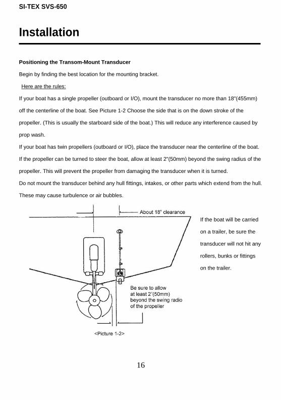
Positioning the Transom-Mount Transducer
Begin by finding the best location for the mounting bracket.
Here are the rules:
If your boat has a single propeller (outboard or I/O), mount the transducer no more than 18"(455mm)
off the centerline of the boat. See Picture 1-2 Choose the side that is on the down stroke of the
propeller. (This is usually the starboard side of the boat.) This will reduce any interference caused by
prop wash.
If your boat has twin propellers (outboard or I/O), place the transducer near the centerline of the boat.
If the propeller can be turned to steer the boat, allow at least 2"(50mm) beyond the swing radius of the
propeller. This will prevent the propeller from damaging the transducer when it is turned.
Do not mount the transducer behind any hull fittings, intakes, or other parts which extend from the hull.
These may cause turbulence or air bubbles.
If the boat will be carried
on a trailer, be sure the
transducer will not hit any
rollers, bunks or fittings
on the trailer.

SI-TEX SVS-650
17
Installation
Mounting the Transom-Mount Transducer
Follow these instructions if you are installing the transom-mount transducer.
1st). On a boat with a fiberglass hull, the leading edge of the transducer should extend 1/8""(3.2mm) to
1/4""(6mm) below the bottom edge of the hull. See picture 1-3. On an aluminum hull, the transducer
should extend a bit more - 1/4"(6mm) to 3/8"(9mm). If the boat will be operated at high speeds, the
transducer may be mounted closer to the centerline of the hull.
2nd
) The lower surface of the transducer should tilt down toward the rear at a slight angle (2° to 5°).
The mounting bracket includes a wedge. Depending on the angle of the transom on your boat, you
may need this wedge to get the correct angle for the bottom of the transducer.
3rd
) Looking at the rear of the boat, be sure the bracket is vertical (perpendicular to the water line).
4th
) Hold the bracket (and the wedge, if used) against the transom and trace the position of the screw
slots.
5th
) Remove the bracket. The screws in the outer slots should be placed about 1/4"(6mm) up from
the bottom of each slot. The screw in the center slot should be placed 1/4" (6mm) down from the top.
(This will allow you to adjust the bracket up or down a bit.)
Drill pilot holes 3/4""(19mm) deep. Use a 9/64" (3.5mm) drill bit. To prevent drilling too deeply, wrap
masking tape around the drill bit about 7/8" (22mm) from the tip. Drill in only as far as the tape marker.
If you are attaching the bracket to a fiberglass hull, you can minimize any surface cracking of the gel
coat. Before drilling each pilot hole, drill a shallow hole (chamfer) at each location about 1/16" (1.5mm)
deep. Use a 1/4"(6mm) drill bit.
6th
) Attach the bracket to the hull using the pinhead screw with flat washers. Before you tighten the
screws, apply a good-quality marine sealant to the pilot hole. This will protect the hull from water
penetration. Do not tighten the screws completely yet.

SI-TEX SVS-650
18
Installation
7th
) Tilt the transducer in the brackets until it is positioned as illustrated in Picture 1-3
8th
) Once the bracket is in the correct position, you can tighten the screws.

SI-TEX SVS-650
19
Installation
Installing the Power Cable-
1st) The SVS-650 is provided with a 6-foot power & data cable as standard equipment. Connect the
power leads directly to the main battery isolation switch or breaker, or route the power leads to the DC
power distribution panel. At the power source, connect the red wire to the positive terminal (+), and
the black wire to the negative terminal (-).
(NOTE: the SVS-650 is internally protected if you accidentally reverse the polarity of the power wires.)
2nd
) Attach the red or positive wire to a 5 amp circuit breaker if possible.
3rd
) Attach the Black wire to the Gnd/Common connection point.
4th
) To prevent any interference or electrical noise, separate the SVS-650 power wiring as much as
possible from other devices.
5th
) If you need to extend the power wiring by more than 10 feet, use a larger wire size. This will
allow the wires to deliver the correct voltage in spite of the longer wire distance. For runs of 20 to 35
feet, use #14/2 AWG wire. If you need to extend the power wiring, be sure all electrical connections
are solid and durable. Insulate all connections using heat-shrink tubing or high quality electrical tape.
You may use crimp connectors or a terminal strip, but be sure to use good-quality marine-grade parts.
6th
) Plug in the power cable at the rear of the display unit.
7th
) When you press the Power button, the display unit should turn on. If the unit will not turn on and
you suspect that you may have reversed the power connections, check the DC power lines all the way
back to the battery. If the polarity is not correct, reconnect the leads properly and try again.

SI-TEX SVS-650
20
Installation
NMEA-0183 Interfacing to a GPS
NMEA-0183 Sentence Descriptions
$GPDBT Depth below transducer
$GPDPT Depth
$GPMTW Water temperature
$GPTLL Target latitude and longitude
$GPVHW Water speed and heading
$GPGGA Global positioning system fix data
$GPVTG Course over ground and ground speed
$GPRMC Recommended minimum specific GNSS data
NMEA-0183 Data Connections: Data connections on the SVS-650 are made via the combination
Power & Data Cable supplied as standard equipment with the unit for NMEA-0183 devices such as
GPS Navigators or Chart plotters.
Power, Data Input & Output Connections:
Pin #1 – Black Wire = Gnd/Common
Pin #2 – Red Wire = Pwr+ (12~36vdc)
Pin #3 - White Wire = NMEA Data Input +
Pin #4 - Green Wire = NMEA Data Return (Ground)
Pin #6 - Yellow Wire = NMEA Data Output +

SI-TEX SVS-650
21
Power I/O and Transducer connector wiring
DESC
RIP
TIO
N
DW
G.
NO
.
DES.
BY
NO
NE
SC
ALE
PER
'N
MO
DEL
CH
K.
BY
MATER
IAL
DR
A.
BY
---
Y.S
. KIM
SI-
TEX M
AR
INE E
LEC
TRO
NIC
S
DATE
02.2
3.2
007
SVS-650
Y.S
.KIM
Pow
er
& I/O
Cable
650-0001
Y.S
. KIM
G.T
.RYU
Pow
er
Cable
PIN
#W
IRE C
OLO
RFU
NC
TIO
N
1 2
BLAC
K
RED D
ata
Input/
Out C
able
PIN
#W
IRE C
OLO
RFU
NC
TIO
N
3 4 5 6 7 8
WH
ITE
GREEN
GREY
YELLO
W
BRO
WN
BLU
E
GN
D/C
OM
MO
N
PW
R+(1
2~
36V)
7 6
54
3
2
18
7 6
54
3
2
18
INPU
T +
INPU
T -
NC
OU
TPU
T+
NC
NC

SI-TEX SVS-650
22
Operation of the SVS-650
Fish finder Modes:
The SVS-650 Fish finder modes are selectable for single frequency or dual frequency, and split screen
functions, for example bottom zoom or bottom lock.
FISH FINDER MODES
Normal (200khz)
Bottom Zoom (200khz)
Bottom Lock (200khz)
Normal (50khz)
Bottom Zoom (50khz)
Bottom Lock (50khz)
Normal (200/50khz)
Bottom Zoom (200/50khz)
▶ pressing the [MODE] key allows you to select the following fish finder display modes:
1. Normal (200 kHz or 50 kHz)
Normal 200 kHz mode is best used in shallow water up to 200ft for the highest detailed image.
Normal 50 kHz mode is most effective in depths of water deeper than 100ft, and should be used when
working in very deep water depths. The Normal mode displays the sounder image with the surface at
the top of the screen and the bottom in the lower portion of the screen. The depth scale on the right
side of the screen indicates the depth range selected. Bottom contours and fish echoes are displayed
at the depths where they are detected. If the depth Range is set manually to a value less than actual
water depth, bottom echoes are not displayed, but all other echoes within the Range setting are
displayed. For example if you set the range to 80ft scale when you are in 600ft of water the bottom
will not be shown on the screen but any fish images shallower than 80ft will be shown on the screen.

SI-TEX SVS-650
23
Operation
2. Bottom Zoom (200 KHz or 50 kHz)
Bottom Zoom magnifies the sounder display from the bottom up toward the surface for a preselected
distance. The bottom contours are displayed and additional contour lines are added at intervals above
the bottom to aid in determining distances of echoes from the bottom. Use the Sounder Menu to set
the Bottom Zoom Range. Choices are 8.2ft, 16.4ft, 32.8ft, 65.6ft. Default setting is 8.2ft
Bottom Zoom mode is not effective in less than 10ft of water. Bottom zoom mode is selectable for
single frequency or dual frequencies.
3. Bottom Lock (200 KHz or 50kHz) Bottom Lock divides the SVS-650 Fish finder main screen image into two sections. The left hand
section displays a Normal Mode image. The right hand section of the screen displays the Bottom lock
image. The bottom appears as a straight line with the Fish images magnified above the bottom.
Bottom Lock mode is very handy for picking out fish swimming close to the bottom when sea
conditions are choppy. A scale appears on the right side of the screen for estimating distances of fish
echoes from the bottom. Use the Fish finder Manu to set the Bottom Lock range, choices are 8.2ft,
16.4ft, 32.8ft, 65.6ft . Default setting is 8.2ft.
Bottom lock mode is not effective in less than 10ft of water.
4. Normal Dual Frequency (200 KHz and 50 KHz)
The Normal mode high frequency (200 KHz) displays on the left side and the Normal mode low
frequency (50 KHz) displays on the right side. Both frequencies transmit simultaneously
5. Bottom Zoom Dual Frequency (200 KHz and 50 KHz)
The Bottom Zoom mode high frequency (200 KHz) displays on the left side of the screen, and the
Bottom Zoom mode low frequency (50 KHz) displays on the right side of the screen. Both
frequencies transmit simultaneously

SI-TEX SVS-650
24
Operation
Display Modes
DISPLAY MODES
Full Fish Finder
Fish Finder + GPS
Fish Finder + Highway
Fish Finder + Steering
▶ [MENU]->[0.Others]->[4.Display Mode]
1. Full Fish finder
Select bar
High Frequency Low Frequency
Speed
Depth
Temp

SI-TEX SVS-650
25
Operation
2. FF + GPS
The GPS display shows receiver status, position in latitude and longitude, course over ground, speed
over ground, date and time.
Receiver status
Date and time
Speed over Ground Course over Ground
Vessel
Coordinates

SI-TEX SVS-650
26
Operation
3. FF + Highway
The highway display provides a 3D view of own ship’s progress toward destination (waypoint).
Destination waypoint name
Destination
waypoint
Bearing from
own ship to
destination
waypoint
Course Over
Ground
Range from own
Ship to destination
waypoint Speed Over
Ground
XTE Alarm Radius
XTE of Vessel
XTE Alarm Radius

SI-TEX SVS-650
27
Operation
4. FF + Steering
The steering display provides steering information such as ship’s speed, course, range, bearing, TTG.
Destination waypoint
name
Bearing from
own ship to
destination
Speed over Ground
Rang
from
own
ship to
destinati
on
Time-To-Go to destination
Bearing from own
ship to destination
waypoint
Course over Ground
Cross-Track-Error

SI-TEX SVS-650
28
Operation
About the Gain control:
The Gain setting controls the ability of the SVS-650 to differentiate between echo’s of different signal
strengths. In general the Gain should be as high as possible, to detect fish and to show bottom
details. However, if the gain is set too high, the unit will begin to see air bubbles in the water, debris
and other background noise. Use a higher gain setting for deeper water, and a lower setting for
shallower water.
1. Auto or Manual Gain selection:
▶ The SVS-650 can be quickly and easily switched between Auto and Manual Gain by simply
pushing on the Gain control knob. (The default setting for gain is Auto Gain)
2. Setting the Gain:
▶Rotate the [GAIN] control to the right to increase the gain. Rotate to the left to decrease the gain.
In Auto Gain the SVS-650 Gain level indicator midpoint is “0” and goes up to +10 or down to -10.
Even in Auto gain it may be advisable to adjust the gain upward for optimum fish finding performance.
In Manual Gain the SVS-650 Gain level indicator starts at 0 and goes up to 50.
(In manual gain a selection of 20 is a normal gain level for shallow water use)
About the STC control:
STC is a very useful function normally only found on more sophisticated commercial echo sounders.
It allows you to reduce the gain in just a small targeted area of the display, without affecting the overall
receiver sensitivity. The STC control will reduce the gain on the screen starting from the surface and
working its way down the screen into deeper depths. You want to be very careful about not using too
much STC because it will also reduce Fish returns if too high of an STC level is applied. Starting at a
zero level turning the STC control to the right will increase the level and start eliminating clutter on the
screen starting at the very top edge of the display, and working down into deeper depths.
(The default setting for the STC level is 0)

SI-TEX SVS-650
29
Operation
About the Main menu:
▶ [MENU]
1. Menu window
2. Setting the menu and changing the value
Choosing the column: Use the key, [▲][▼].
Setting value: Use the [ENT] key
(The default setting for pulse is M) (The default setting for output power is H)
Selected column
Setting value
Red: Chosen

SI-TEX SVS-650
30
Operation
▶ [MAIN MENU]
1. Range
▶ [MENU] -> 1. Range
SVS-650 has two choices for Range Selection MANUAL Range & AUTO Range. In Auto Range the
SVS-650 will select the Range Scale Automatically. In the Manual Range mode the operator of the
SVS-650 controls the Range scale by using the (+ -) Keys on the front panel of the SVS-650,
Choosing the range manually is sometimes preferable in areas where the bottom depth is on the edge
of the preset depth scales of the SVS-650. Choosing the Range scale manually will stop the unit from
automatically jumping between Scales and allow the operator to place the bottom image in a preferred
section of the Screen
(☞ the default range setting is Auto.)
2. Shift
▶ [MENU] -> 2. Shift
The SHIFT function allows you to use the entire display screen of the SVS-650 to enlarge a
designated area of the water column. When you adjust the SHIFT control, the starting point for the
range of the Sounder changes from Zero to whatever is selected for a shift value. For example, if you
increase the shift value to 15ft with a 60ft range selected, the top edge of the display screen will start
at 15ft and the bottom edge of the displayed range will be 75ft. This allows the operator to slide the
display range down without having to select the next higher preset range scale. Effectively using the
entire display as a Zoom window instead of having a split screen Zoom as normally available from
fisfinder mode selection screen.
(☞ the default Shift range setting is 0 ft.)

SI-TEX SVS-650
31
Operation
3. Display menu page 1 of 2
▶ [MENU] -> 3. Display
3-1. A-Scope:
The A-scope function gives an instantaneous display of activity directly under the boat without having
to wait for it to scroll to the left on the display screen.
(☞ the default A-Scope setting is off.)
3-2. Image Speed:
The image speed control selects how quickly the image moves across the screen from right to left.
The image speed changes automatically with different range selections. The Shallower the range
setting the faster the image moves the deeper the range setting the slower the image moves across
the screen. The Image Speed control allows the operator to slow the screen down in shallow ranges
or speed it up in deeper ranges.
(☞ the default Image Speed setting is 1X.)
3-3. White Line
Off / Black / White selections. This function is used to help separate fish that may be swimming very
close to the bottom and blending in with the bottom image. Choice of a Black or White line display
(☞ the default White Line setting is OFF.)
3-4. Bottom Zoom & Bottom Lock Range
Selects the range of the Bottom zoom & Bottom lock windows. Choices of 8.2ft, 16.4ft, 32.8ft, 65.6ft
(The default Bottom Zoom & Bottom Lock Range setting is 8.2ft.)
SI-TEX SVS-650
32
Operation
3.5. Depth
(On/Off) The Digital Depth readout indicates the actual measured water depth on the screen.
(☞ the default setting is ON.) (Note: bottom image must be on the screen for readout to operate)
3.6. Depth Font
Selects the depth range scale line font sizes on the screen. Choices Small / Normal / Large
(☞ the default Depth Font setting is Normal.)
3.7. TEMP
(On/Off) Turns the Digital Surface Temperature readout on or off.
(☞ the default Temp setting is ON.)
3. Display menu page 1 of 2
3.8. TEMP Font
Select the Digital Surface Temperature readout font size on the screen. Choices Small / Normal /Large
(☞ the default Temp Font setting is small.)
3-9. Speed
(On/Off) Turns the Digital Boat Speed readout on or off.
(☞ the default Speed setting is Off.)
3-0.Speed Font
Selects the Digital Boat Speed readout font size on the screen. Choices Small / Normal /Large
(☞ The default setting is normal.)
3. Display menu page 2 of 2 (to change to menu page 2, press [MENU])
▶ [MENU] -> 3. Display-2/2>[MENU]
3-1. Fish Symbol
(On/Off) Turns the Fish Symbols on or off. 4 different size fish symbols, colors change with size
(Note: Fish Symbols are only an estimation, doesn’t positively indentify fish targets)
(☞ the default setting is off.)

SI-TEX SVS-650
33
Operation
4. Rejection ▶ [MENU] -> 4. Rejection
4-1. Interference
The Interference rejection control allows the operator to reduce or eliminate interference from other
depth finders. The choices are off / L / H
(☞ the default Interference setting is L.)
4-2. Noise
The Noise rejection control helps to eliminate electrical noise interference from onboard sources.
The choices are off / L / M / H
(☞ the default setting is M.)
5. Color
▶ [MENU] ->5. Color
5-1. Bottom enhance
This function controls the color range for the bottom return. The higher the level the darker the color
range of the bottom return image. The choices are off / L / M/ H
(☞ the default setting is M)
5-2. Color Rejection
The Color Rejection feature is very useful for eliminating screen clutter without having to lower the
gain level. The SVS-650 has 16 color levels that it uses to differentiate between strong and weak
signal returns. By turning off some of the lighter colors the operator can eliminate returns from things
like turbulence in the water. (☞ the default Color rejection setting is all colors on)
5-3. Screen Color
Selects the Screen background color of the Fish finder for best view ability. There are 5 different
background Screen Color choices - light blue, dark blue, white, black, and light blue with 8 color levels.
(☞ the default Screen Color setting is dark blue)

SI-TEX SVS-650
34
Operation
6. Pulse
▶ [MENU] -> 6. Pulse
This menu function chooses the Pulse length of the transducer output. Pulse lengths are
automatically selected based on the depth range. With the Pulse control the operator can select the
pulse length preferences. From 0.5X up to 1.5X, the short pulse lengths are used in shallow water
and give more detail, the longer pulse lengths are used in deeper water for better depth penetration.
(☞ the default setting is M = 1X.)
7. Output Power
▶ [MENU] -> 7. Output Power
This menu function selects that output power from the SVS-650 to the installed transducer. The
default for the SVS-650 is for full power output of 600 watts RMS. When working in shallow water it
may be preferable to choose a lower output power level to help reduce screen clutter from excess
output signal level. The choices are off / L / M / H
(☞ the default setting is H)

SI-TEX SVS-650
35
Operation
8. Alarm
▶ [MENU] -> 8. Alarm
8-1. Shallow Depth Alarm:
(On/Off) Activates Alarm if Depth is shallower then selected Shallow Depth Range
(☞ the default setting is OFF.)
8-2. Shallow Depth Alarm Range:
Set’s the range of the Shallow Depth Alarm If the depth of water below the vessel is shallower than
the selected Depth an alarm will sound and the Shallow Depth warning message will pop up on screen
(☞ the default setting is 33ft)
8-3. Deep Depth Alarm:
(On/Off) Activates Alarm if Depth is Deeper then selected Deep Depth Range
(☞ the default setting is OFF.)
8-4. Deep Depth Alarm Range:
Set’s the range of the Deep Depth Alarm If the depth of water below the vessel is Deeper than the
selected Depth an alarm will sound and the Deep Depth warning message will pop up on screen
(☞ the default setting is 33ft)
8-5. Low Temp Alarm:
This function sounds an alarm if surface water temperature goes below the selected level.
(☞ the default setting is OFF.)
8-6. Low Temp Range:
Sets the range of the low water temperature alarm. If the surface water temperature goes below the
set value an alarm will sound and the Low Temp warning message will pop up on screen.
(☞ the default setting is 32.0’F degree)

SI-TEX SVS-650
36
Operation
8-7. High Temp Alarm:
This function sounds an alarm if surface water temperature goes above the selected level.
(☞ the default setting is OFF.)
8-8. High Temp Range:
Sets the range of the high water temperature alarm. If the surface water temperature goes above the
set value an alarm will sound and the High Temp warning message will pop up on screen.
(☞ the default setting is 32.0’F degree)
8-9. Fish-School Alarm: (On/Off) This function sounds an alarm if a school of fish passes through the selected alarm area.
(☞ the default setting for the Fish-School Alarm is Off)
8-0. F.S. Depth Alarm: Sets the shallow range of the fish school depth alarm. If the school of fish passes below the set
depth an alarm will sound and the Fish-School alarm warning message will pop up on screen.
(☞ the default setting for the F.S. Depth Alarm is 33ft.)
8-2-1. F.S. Depth Range: (Press the MENU key to access menu page 2) Sets the F.S. Alarm Depth Range. Sets the maximum range for the Fish-School Alarm. If a school
of fish passes above the set depth an alarm will sound and the Fish-School alarm warning message
will pop up on screen.
(☞ The default setting for the F.S. Depth Alarm is 164ft.)
8-2-2. Alarm Interval:
The Alarm Interval sets the period of time the Fish-School must be on the screen before the alarm will
sound. (☞ The default setting is middle)
8-2-3. Color Level:
Sets the Color Level that a School of fish must display before it will set off the Fish-School Alarm.
This helps reduce false alarms. (☞ The default Color level setting is Red)
SI-TEX SVS-650
37
Operation
9. General Setup
▶ [MENU] -> 9. General Setup
9-1. System version
It contains System Software version, and Build Date for maintenance and upgrade purposes.
9-2. Unit Setup (press right arrow key to access unit setup)
9-2-1. Distance/Speed Unit
Select desired unit of measure for distance and speed readouts.
Choose from:
Nautical mile/Knots (Nm/Kt) Kilometer/kilometers per hour (km/kmh),
Statue mile/Mph (Yd/mph) (☞The default setting is nm/kt)
9-2-2. Depth
Select desired unit of measure for depth units. (☞The default setting is FEET.)
- M: Meter unit
- Ft: Feet unit
- Fm: FATHOM unit
- Ifm: Italian FATHOM unit
- Jfm: Japanese FATHOM unit
9-2-3. Temperature
Select desired unit of measure for temperature of the surface water.
Choose from: Celsius (℃), or Fahrenheit (℉).
(☞The default setting is Fahrenheit.)

SI-TEX SVS-650
38
Operation
9-3. Time Format: Sets your preferred time between 12 hour and 24 hour.
(Press the right arrow key to access time & date setup)
(☞The default setting is 12 hour.)
9-4. Date Format
Select the Date format
(☞The default setting is 1.)
- 1: YY-MM-DD (year/month/day)
- 2: DD-MM-YY (day/month/year)
- 3: MM-DD-YY (month/day/year)
9-5. Output Sentence
The NMEA-0183 output sentences can be set to On/Off.
NMEA Description Default
$GPDBT Depth below transducer On
$GPDPT Depth On
$GPMTW Water temperature Off
$GPTLL Target latitude and longitude On
$GPVHW Water speed and heading Off
$GPGGA Global positioning system fix data Off
$GPVTG Course over ground and ground speed Off
$GPRMC Recommended minimum specific GNSS data Off
9-6. Simulator
The SVS-650 has a built-in simulation mode. This is very useful for learning how to operate
the SVS-650 at home away from your boat. (☞The default setting is off.)

SI-TEX SVS-650
39
Operation
9-7. Language:
The SVS-650 supports five different languages, English, Spanish, French, Portuguese, and
Vietnamese. Select the desired language and press the [ENTER] key, The SVS-650 turns off
and reboots the system for the new language.
9-8. Reset
Master reset returns all settings to the initial default settings.
▶ [ENTER]: reset without deleting user data. (Preserves Event memory & Screen Captures)
▶ [FUNC] -> [ENTER]: returns to the initial system default settings*
(*All user data, event memories and screen captures will be deleted)
9-9. Buzzer
(On/Off) Turns the Keypad Beeper on or Off
(☞The default setting is on.)
9-0. Speed Source
Selects the boat speed information source either the transducer paddle wheel or NMEA-0183
- InsideSensor: Uses the transducer paddle wheel sensor for Speed thru the water
- NMEA: Use the external input value for NMEA-0183 Speed over Ground
(☞The default setting is InsideSensor.)

SI-TEX SVS-650
40
Operation
0. Others (CUSTOMIZING THE FUNCTION KEY & EVENT KEY)
▶ [MENU] -> 0.Others (press right arrow key to access others menu)
0-1. Key Setup
Customizes the set up of the [FUNC] key and [EVENT] keys on the SVS-650.
0-1-1. [FUNC] key:
The function key operation can be changed to any of the following choices:
(☞ the default setting for the function key is Display Mode.)
[FUNC] KEY SETUP
1.Display Mode
2.Image Speed
3.Color Rejection
4.Noise Rejection
5.Shift
6.Bottom Zoom Range
7.White Line
8.Pulse
9.Output Power
0.Reset
0-1-2. [EVENT] key:
Customizes the operation of the event key:
(☞ the default setting is Capture.)
- Input Mark: Saves present position as a waypoint in the SVS-650 memory
- Navigation: Brings up the waypoint list and allows the operator to Goto a selected WP
- Capture: Takes a Snap Shot of the Fish Finder Screen and stores in memory

SI-TEX SVS-650
41
Operation
0-2. Mark Setup
Setting up the Mark List, Edit, and Alarm.
0-2-1. Mark List:
Shown the mark list and it is available to set up or edit the mark on the list.
☞ Edit
Edit numbers, symbols, and colors of Mark.
i) Editing Character
[←],[→]:
Move the position
[↑], [↓]: change the character.
[ENTER]: choice
[CLEAR]: save and Exit
SI-TEX SVS-650
42
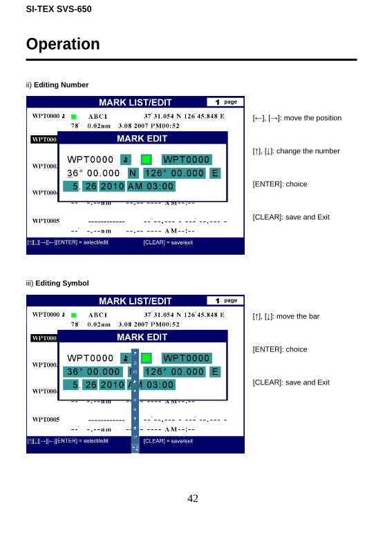
Operation
ii) Editing Number
[←], [→]: move the position
[↑], [↓]: change the number
[ENTER]: choice
[CLEAR]: save and Exit
iii) Editing Symbol
[↑], [↓]: move the bar
[ENTER]: choice
[CLEAR]: save and Exit

SI-TEX SVS-650
43
Operation
iv) Editing Color
[↑],[↓]: move the bar
[ENTER]: choice
[CLEAR]: save and Exit
v). Goto Mark
[↑],[↓]: move the bar
[EVENT]: goto
0-2-2. Alarm
0-2-2-1. Arrival Alarm:
When you approach into the
waypoint range, it gives you a
notice with alarm.
(☞ The default setting is OFF.)

SI-TEX SVS-650
44
Operation
0-2-2-2. Arrival Radius:
It is to adjust the range of arrival from your waypoint. If you have a route, it changes to the next
waypoint automatically.
(☞ The default setting is 0.05nm.)
0-2-2-3. XTE Alarm:
If you are off course, it gives you a notice with alarm.
(☞ The default setting is OFF.)
0-2-2-4. XTE Radius:
It is to adjust the range of the off course.
(☞ The default setting is 0.05nm.)
0-2-3. Stop Navigation:
Stops the present navigation.
0-3. Capture List
Available to display and delete the capture file
▶ [MENU]->[5.Capture List]
Select bar
Order File name

SI-TEX SVS-650
45
Operation
VRM
▶ Press [VRM]
The VRM (movable marker) shown by the green line can be moved up and down.
It is a convenient way to measure the depth by aligning with a target such as a school of fish.
VRM
SI-TEX SVS-650
46

SI-TEX SVS-650
47
CERTIFICATE OF LIMITED WARRANTY
Providing you present a valid proof of purchase, SI-TEX Marine Electronics Inc. warrants all parts of
each new product against defects in material and workmanship under normal use and will repair or
exchange any parts proven to be defective at no charge for a period of two years for parts and one
year for labor from the date of purchase, except as provided below under Limited Warranty
Exceptions. Defects will be corrected during normal working hours by an authorized SI-TEX Marine
Electronics Inc. dealer, Service Center, or at the SI-TEX office in Riverhead, NY. There will be no
charge for labor for a period of one year from the date of purchase, except as provided below under
Limited Warranty Exceptions.
This Warranty and Proof of Purchase must be made available to the authorized SI-TEX Marine
Electronics Inc. service location or dealer at the time of service.
LIMITED WARRANTY EXCEPTIONS
SI-TEX Marine Electronics Inc. will not be responsible for equipment which has been subjected to
water or lightning damage, accident, abuse, or misuse, nor any equipment on which the serial number
label has been removed, altered or mutilated.
SI-TEX Marine Electronics Inc. assumes no responsibility for damage incurred during installation.
This Limited Warranty is effective only with respect to the original purchaser.
Any cost associated with transducer replacement, other than the cost of the transducer itself, is
specifically excluded from this Limited Warranty.
Travel costs incurred will not be accepted for SI-TEX Marine Electronics Inc. products.
THERE ARE NO WARRANTIES, WHICH EXTEND BEYOND THE DESCRIPTION OF THE FACE
HEREOF.

SI-TEX SVS-650
48
SPECIFIC EXCLUSIONS
Charges for overtime, stand-by, holiday, and per diem are specifically excluded from the Limited
Warranty. Installation workmanship or materials except as provided directly by SI-TEX Marine
Electronics Inc. are not covered by this Limited Warranty. SI-TEX Marine Electronics Inc. equipment
or parts thereof, which have been repaired or altered except by an authorized SI-TEX Marine
Electronics Inc. dealer or service center, are not warranted in any respect. Transducer, software
update, battery, are items excluded from the two-year warranty and are covered by warranty for a
period of one year for both parts and labor. SI-TEX Marine Electronics Inc. will not, at any time,
assume any costs or labor charges for checkout or external line fuse replacement or problems not
found to be at fault in equipment itself.
THERE ARE NO WARRANTIES OR GUARANTEES EXPRESSED OR IMPLIED WHICH EXTEND
BEYOND THE DESCRIPTION ON THE FACE HEREOF, INCLUDING WARRANTIES OF FITNESS
FOR A PARTICULAR PURPOSE AND MERCHANTABILITY. SI-TEX MARINE ELECTRONICS INC.
HAS NO OTHER LIABILITY TO PURCHASE FOR DIRECT OR CONSEQUENTIAL DAMAGE OR
ANY THEORY INCLUDING ABSOLUTE LIABILITY, TORT, OR CONTRACT. THIS LIMITED
WARRANTY CANNOT BE ALTERED OR MODIFIED IN ANY WAY AND SHALL BE INTERPRETED
IN ACCORDANCE WITH THE LAWS OF THE STATE OF NEW YORK. THIS WARRANTY IS
LIMITED TO THE CONTINENTAL U.S.A., ALASKA, HAWAII, AND CANADA.

SI-TEX SVS-650
49
HOW TO OBTAIN SERVICE UNDER THIS WARRANTY
If you encounter problems during the installation or operation of this product, or cannot find the
information you need, please contact SI-TEX Customer Service.
The contact numbers and e-mail address for SI-TEX Customer Service are:
SI-TEX Main Office…….………..+1-631-996-2690
SI-TEX Fax..………………….…..+1-631-996-2693
SI-TEX Service E-mail address: [email protected]
SI-TEX Customer Support E-mail address: [email protected]
Online Service Request form: http://www.si-tex.com/2011_onlineservicerequestform.htm
SI-TEX Main Office Address:
25 Enterprise Zone Drive, Ste 2
Riverhead, NY 11901
Technical Support is available from 9:00 AM to 5:00 PM Eastern Standard Time, Monday through
Friday.