ta1 english - off-higway truck.xls
TRANSCRIPT

TA-1 Visual Inspection for Off-Highway Trucks
SMCS - Job Code - 540 Component Code - 753S
Serial Number : Inspector : Temperature :
Model : 797b Work Order : Time :
Engine S/N: SMU: Date :
Manufacturer : Unit Location:
Status of the Machine
The status recommendation of your Off-Highway Truck is:Normal
Cat dealerAddressContact
Customer AddressContact
Note: Review Machine & S·O·S History and check for Active Service Letters prior to inspection.

Visual Inspection for Off-Highway TruckStatus assessment M – Monitor A – Action Blank – Not Applicable
1. Prepare Machine InspectionStatus Description Comments
1.1 Normal Check with customer for operator complaints
1.2 Normal Prepare the machine for the inspection
1.3 Normal Perform safety/preparatory inspection
1.4 Normal Download machine fault codes
1.5 Normal Observe engine exhaust colors
1.6Normal
1.7
1.8
1.9
1.10
Item No. Additional Comment
ü– Normal
Listen for unusual noises(hydraulic pumps, engine, transmission, and axles)

2. Lower-Level InspectionStatus Description Comments
2.1 Monitor Tires and Rims
2.2 Normal Front Wheels and Brakes
2.3 Normal Rear Final Drives, Brakes and Wheel Spindles
2.4 Normal Differential Housing
2.5 Normal Drive Shaft
2.6 Normal Transmission and Transfer Gears
2.7 Action Rear Axle Housing Support
2.8 Normal Hoist Control Valve
2.9 Normal Rear Engine/Torque Converter Mounts
2.10 Normal Brake Accumulator
2.11 Normal Oil Coolers and Lines
2.12 Action Steering Cylinders and Steering Linkage
2.13Normal
2.14 Normal Secondary Steering/Brake Release Pump
2.15 Normal Engine Oil Pan
2.16 Normal Machine Frame
2.17
2.18
2.19
Item No. Additional Comment
Engine Damper, Front Engine Trunnion Mounts and Support Mounts

3. Middle Level Inspection
Status Description Comments
3.1 Mud Flaps
3.2 Front Suspension Cylinders
3.3 Fuel Lines, Fuel Pump and Fuel Filter Base
3.4 Exhaust Manifold
3.5 Turbocharger
3.6 Brake Hydraulic Lines and Components
3.7 Steering Valves
3.8 Hydraulic Tank
3.9 Fuel Tank
3.10 Rear Suspension Cylinder
3.11 Ground Level Electrical Components
3.12 Work Lights
3.13 Radiator, Aftercooler and Condenser
3.14 Cylinder Head and Valve Cover
3.15 Water Pump
3.16
3.17
3.18
Item No. Additional Comment

4. Upper-Level Inspection
Status Description Comments
4.1 Steps and Handrails
4.2 Hood and Platform
4.3 Precleaner and Air Cleaner
4.4 Pulleys, Belts, Compressor Clutch and Alternator
4.5 Cooling Fan, Fan Guard and Shroud
4.6 Steering Tank
4.7 Cab Exterior
4.8 Cab Interior
4.9 Cab Mounts
4.10
4.11 Radiator Cap
4.12 Hydraulic Pump Compartment
4.13 Auto-Lube Pump, Tank and Injectors
4.14 Rear Brake Lines and Components
4.15
4.16
4.17
Item No. Additional Comment
Upper and Lower Radiator Lines, Air Inlet Lines and Aftercooler Lines

5. Implement/Attachment Inspection
Status Description Comments
5.1 Hoist Cylinder
5.2 Truck Body
Body liner
Canopy
Heated Body Exhaust Ports
Rock Ejectors
Rocker Shoes, Rest Pads & Shims
Frame Rest Pads & Shims
Body Position Switch
5.3
5.4
5.5
Item No. Additional Comment
6. Site Conditions# Status Description
6.1 Ambient Temperature
6.2 Altitude
6.3 Haul Road Grade
NORMAL: -18° to 32°C (0° to 90°F)
MONITOR: 32° to 46°C or -18° to -29°C (90° to 115°F or 0° to -20°F)
ACTION: Above 46°C or Below -29°C (Above 115° or Below -20°F)
NORMAL: 0 to 1524 m (0 to 5000 ft)
MONITOR: 1524 to 3048 m (5000 to 10,000 ft)
ACTION: Above 3048 m (Above 10,000 ft)
NORMAL: Flat

6.4 Haul Road Condition
6.5 Humidity
6.6 Air Quality
6.7 Underfoot Condition
6.8 Machine Utilization
6.9 Equipment Role
6.10 Working Material
6.11 Maintenance Practices
MONITOR: Mild
ACTION: Steep
NORMAL: Positive Banking, Gradual Turns, Good Erosion Control
ACTION: Negative Banking, Sharp Turns, Poor Erosion Control
NORMAL: Below 25%
MONITOR: 25 to 60%
ACTION: Above 60%
NORMAL: No Dust
MONITOR: Light Dust
ACTION: Heavy Dust
NORMAL: Dry Flat Surface
MONITOR: Moderate Grades, Mixture of Muddy / Dry Surfaces
ACTION: Steep Grades, Muddy, Snow, Ice
NORMAL: 0 to 10 Hours
ACTION: Above 10 hours
NORMAL: Utility
MONITOR: Support
ACTION: Production
NORMAL: Uncompacted, Low Abrasion
MONITOR: Moderately Compacted, Moderate Abrasion
ACTION: High Abrasion, Compacted, Dense
NORMAL: Excellent
MONITOR: Good
ACTION: Poor

6.12 Primary Industries
6.13
6.14
6.15
Item No. Additional Comments
Other Remarks

Visual Inspection for Off-Highway TruckBlank – Not Applicable
1. Prepare Machine InspectionComments
Additional Comment

2. Lower-Level InspectionComments
Additional Comment

3. Middle Level Inspection
Comments
Additional Comment

4. Upper-Level Inspection
Comments
Additional Comment

5. Implement/Attachment Inspection
Comments
Additional Comment
6. Site Conditions


Additional Comments
Other Remarks

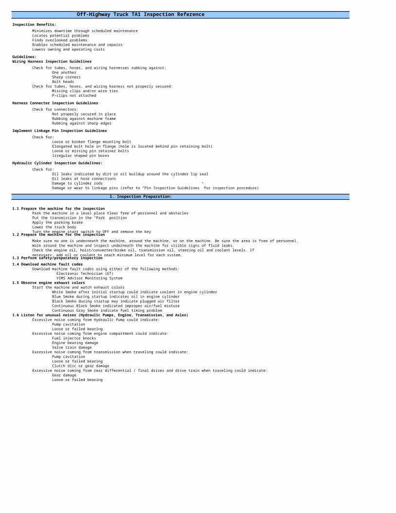
Off-Highway Truck TA1 Inspection Reference
Inspection Benefits:
Minimizes downtime through scheduled maintenanceLocates potential problemsFinds overlooked problemsEnables scheduled maintenance and repairsLowers owning and operating costs
Guidelines:Wiring Harness Inspection Guidelines
Check for tubes, hoses, and wiring harnesses rubbing against:One another Sharp cornersBolt heads
Check for tubes, hoses, and wiring harness not properly secured:Missing clips and/or wire ties P-clips not attached
Harness Connector Inspection Guidelines
Check for connectors:Not properly secured in placeRubbing against machine frameRubbing against sharp edges
Implement Linkage Pin Inspection Guidelines
Check for:Loose or broken flange mounting boltElongated bolt hole in flange (hole is located behind pin retaining bolt)Loose or missing pin retainer boltsIrregular shaped pin bores
Hydraulic Cylinder Inspection Guidelines:
Check for:Oil leaks indicated by dirt or oil buildup around the cylinder lip sealOil leaks at hose connectionsDamage to cylinder rodsDamage or wear to linkage pins (refer to “Pin Inspection Guidelines” for inspection procedure)
1. Inspection Preparation:
1.1 Prepare the machine for the inspectionPark the machine in a level place clear free of personnel and obstaclesPut the transmission in the “Park” positionApply the parking brakeLower the truck bodyTurn the engine start switch to OFF and remove the key
1.2 Prepare the machine for the inspection
Make sure no one is underneath the machine, around the machine, or on the machine. Be sure the area is free of personnel.Walk around the machine and inspect underneath the machine for visible signs of fluid leaks.
1.3 Perform safety/preparatory inspection
1.4 Download machine fault codesDownload machine fault codes using either of the following methods:
Electronic Technician (ET) VIMS Advisor Monitoring System
1.5 Observe engine exhaust colorsStart the machine and watch exhaust colors
White Smoke after initial startup could indicate coolant in engine cylinder Blue Smoke during startup indicates oil in engine cylinderBlack Smoke during startup may indicate plugged air filterContinuous Black Smoke indicated improper air/fuel mixtureContinuous Gray Smoke indicate fuel timing problem
1.6 Listen for unusual noises (Hydraulic Pumps, Engine, Transmission, and Axles)Excessive noise coming from Hydraulic Pump could indicate:
Pump cavitationLoose or failed bearing
Excessive noise coming from engine compartment could indicate:Fuel injector knocksEngine bearing damageValve train damage
Excessive noise coming from transmission when traveling could indicate:Pump cavitationLoose or failed bearingClutch disc or gear damage
Excessive noise coming from rear differential / final drives and drive train when traveling could indicate:Gear damageLoose or failed bearing
Check the engine oil, hoist/converter/brake oil, transmission oil, steering oil and coolant levels. If necessary, add oil or coolant to reach minimum level for each system.
2 Lower level Inspection:
2.1 Tires and RimsProper inflationCuts, cracks, splits, or busies in the tread or sidewall area
Bumps or bulges may indicate tire separationSafe tread depth
Tread worn down to the built-in wear indicatorsTire cords or exposed fabricUneven tread wear
Cracks, pits from corrosion, or other visible damage to rims2.2 Front Wheels and Brakes
Check the following for leaks:Sealing surface between the wheel cover and the wheel hubOil leakage around the drain and fill plugsDou-cone seal located between the wheel hub and the brake pack housingDou-cone seal located between the brake pack housing and the axle housingSealing surfaces between the various brake pack housing componentsBrake cooling oil & hydraulic oil lines & connectors
If equipped, check the magnetic plug for metal particles.
2.3 Rear Final Drives, Brakes & Wheel SpindlesCheck the following areas for leaks:
Sealing surface between the axle cover and the final drive planet carrierOil leakage around the drain and fill plugsSealing surface between the final drive housing and the rear wheel housingDou-cone seal located between the rear wheel housing and wheel spindleDou-cone seal located between the brake pack housing and the rear wheel housingSealing surfaces between the various brake pack housing componentsBrake cooling oil & hydraulic oil lines & connectors
If equipped, check the magnetic plug for metal particles.2.4 Differential Housing
Check differential housing for leaks in the following areas:Sealing surface between the differential housing and the transmission housingSealing surface between the differential housing and the wheel spindlesOil leakage around the drain and fill plugs
If equipped, check the magnetic plug for metal particles.Check the following for loose or damaged axle housing joints, bolts, pins, retainers:
Lateral control armTransmission housing & axle housing support
2.5 Drive ShaftCheck for :
Loose or missing U-joint retainer boltsWorn or loose U-joints or drive shaft spline
Grease leaking from U-joint seals or from drive shaft splineGrease leakage in these areas would indicate possible seal damage.
2.6 Transmission & Transfer GearsCheck for :
Leaks around hose connectionsRubbing, damaged, or worn hosesRubbing, damaged, or worn wiring harnesses or connectorsOil leakage around the drain and fill plugsOil or dirt buildup on the transmission and transfer gear housings. If visible, inspect:
Sealing surfaces between axle housing and transmission housingSealing surfaces between transmission housing and transfer gearDrive shaft yoke assembly seal
2.7 Rear Axle Housing SupportCheck for :
Loose or damaged spherical bearing retainer boltsLoose or damaged retainer block mounting boltsIrregular shape pin bores or excessive pin wearDamaged grease lines or fittings
2.8 Hoist Control ValveCheck for:
Leaks around connection points for hose and control valve componentsRubbing, damaged, or worn hosesRubbing, damaged, or worn wiring harnesses and connectors
2.9 Rear Engine / Torque Converter MountsCheck for:
Structural damage to support brackets & engine supportsStructural damage or weld cracks on frame supportsLoose or damaged support mounting bolts
2.10 Brake AccumulatorCheck for:
Leaks around connection points for hosesRubbing, damaged, or worn hosesRubbing, damaged, or worn wiring harnesses and connectors
2.11 Oil Coolers & LinesCheck for:
Leaks around hose connectionsRubbing, cracked, and damaged hosesLoose connectionsImproperly secured hoses
Use a pry bar to pry between yoke and U-joint or between the frame and drive shaft spline to check for movement. Movement in these areas would indicate excessive wear.

2.12 Steering Cylinders and Steering LinkagesCheck steering cylinder for: (Refer to “Hydraulic Cylinder Inspection Guidelines” for inspection procedure)Oil leaks indicated by dirt or oil buildup around the cylinder lip sealDamage to cylinder rodsOil leaks at hose connections
Check steering linkages for:Oil leaks indicated by dirt or oil buildup around the cylinder lip sealDamage to cylinder rodsOil leaks at hose connections
2.13 Engine Damper, Front Engine Trunnion, Support, Trunnion Mounts, Support MountsCheck:
Fluid filled engine damper for fluid leaksTrunnion & Support Mounts for:
Structural damage Loose or damaged bolts Worn or damaged rubber pads
2.14 Secondary Steering / Brake Release PumpCheck for:
Oil leaks at pump connectionsRubbing, damaged, or worn hoses or tubesRubbing, damaged, or worn wiring harnesses or connectorsLoose wiring connections
2.15 Engine Oil PanCheck for oil accumulation on the bottom of the oil pan.
If oil is found on the pan, inspect the following:Check for leaks around the oil pan mounting flange.Check for leaks around the oil level sensor, drain valve, dipstick tube, turbo Lube return.
2.16 Machine FrameCheck for:
Damage to frameStructural cracksCracked welds
Reference Special Instructions REHS1227 (Small OHT) or REHS0541 (Large OHT)for detailed instructions regarding frame maintenance, inspections, & repair.
3 Middle Level Inspection:
3.1 Mud FlapsCheck for:
Bent or damaged fendersPotential interference with tires
Loose or missing mounting nuts, bolts, brackets, straps3.2 Front Suspension Cylinders
Check for:Oil leaks indicated by dirt or oil buildup around the cylinder lip sealNicked, scored, pitted cylinder rodsLoose or missing cylinder boot Structural damage or weld cracksDamaged or loose steering arm or cylinder cap boltsDamaged or loose suspension cylinder mounting boltsImproperly lubricated bearing capBroken or damaged grease lines, grease fittings, or grease seals Rubbing, damaged, or worn wiring harnesses or connectorsCylinder charge height (Dimension “x”) Reference the OMM & T&A manual for measurement specifications.
3.3 Fuel Line, Pump & Filter BaseCheck fuel priming pump, primary/ secondary fuel filter bases, and fuel injection pump for:
Damaged, rubbing, or worn fuel lines or hydraulic linesLoose connectionsLeaks
3.4 Exhaust ManifoldCheck for:
Black soot indicating a loose, broken, damaged connection around the following sealing surfaces:Where the exhaust manifold bolts to the cylinder headClamps and baffles between manifold segments on each cylinder headWhere the exhaust manifold bolts to the turbocharger turbine inlet
Cracks or other damage in the manifold housing3.5 Turbocharger
Check for:
Loose connections at the jointsLoose or broken mounting bolts
Oil leakage around the turbocharger oil lineDirt tracks which may indicate air inlet or boost air leaks due to loose or damaged hoses, clamps on:
Air inlet tubes and compressor housingTurbo boost air linesTurbo wastegate and wastegate boost lines
3.6 Brake Hydraulic Lines & ComponentsInspect the following components:
Service Brake ValveCab Brake ManifoldFront Brake Slack Adjuster located on the left hoist cylinder frame support
Check for: Leaks around hose connectionsRubbing, damaged, or worn hosesRubbing, damaged, or worn wires/harness/connectors
Black soot around the areas where the turbocharger bolts to the to the exhaust manifold or to the exhaust pipe. This would indicate:

3.7 Steering ValvesInspect the steering pressure control valve & steering disable valve for:
Leaks around connection points for hose and control valve componentsRubbing, damaged, or worn hosesRubbing, damaged, or worn wiring harnesses and connectors
3.8 Hydraulic TankCheck:
Upper & lower mounts for loose mounting bolts and structural cracks on frame mounting bracketsTank caps seals for damageBreather for dirt and debris buildupHydraulic lines for leaks, loose or damaged connectionsSight glass covers for damage. Sight glasses for damage or leaks
3.9 Fuel TankCheck for:
LeaksStructural damage to tank, weldsBreather and fill cap Loose or damaged boltsWorn or damaged rubber mounts
3.10 Rear Suspension CylindersCheck for:
Oil leaks indicated by dirt or oil buildup around the cylinder lip sealNicked, scored, pitted cylinder rodsLoose or missing cylinder boot Structural damage or weld cracksBroken or damaged grease lines or fittingsLoose, damaged, or missing pin retaining boltsIrregular shaped pin boresRubbing, damaged, or worn wiring harnesses or connectorsCylinder Charge Height (Dimension “x”) Reference the OMM & T&A manual for measurement specifications
3.11 Ground Level Electrical ComponentsCheck the following for proper operation:
Compartment covers, latches, hingesBattery disconnect switchEngine disconnect switchAuxiliary start (jump start) receptacleStarter & alternator circuit breakersMachine lockout control & lightEngine lockout control & lightMachine access light switch
3.12 Work LightsCheck road lights, turn signals, hazard flashers, work lights, and other lights for:
Proper operationCracked or broken lensesDamaged wiring harnesses Loose or damaged mounting brackets
3.13 Radiator, Aftercooler & AC CondenserCheck for:
Plugged screens Plugged cores Damaged fins
Note: Inspect both sides of cores, when possible3.14 Cylinder Head and Valve Cover
Check for:Oil and dust buildup around the sealing surfaces of the valve covers or cylinder head gasket. Leakage in this area would indicate:
Loose connection at the jointDamaged gasket or seal
3.15 Water PumpCheck Primary (& Auxiliary) Pump for:
Coolant leaks around water pump mounting flangeCoolant leaks through the weep hole in the water pump housing
4 Upper Level Inspection:
4.1 Steps & HandrailsEnsure that steps and handrails are in place. Check for:
Damaged, missing, or loose boltsDamage to steps or handrailsExcessive dirt or debris
4.2 Hood & PlatformCheck for:
Debris or excessive dirt on service platformLoose or damaged bolted access coversProper function of access panels, latches, hingesLoose or damaged platform mounts, bolts
4.3 Pre-cleaner and Air CleanerCheck for:
Dirt and/or debris in the air pre-cleanerLoose or damaged hose clamps on air inlet tubeLoose or damaged air cleaner covers, clamps
4.4 Pulleys, Belts, Compressor Clutch, and AlternatorCheck belts for:
Worn, cracked, or broken beltsProper belt tension
Check for oil leaks around air condition compressor clutch

4.5 Cooling Fan, Fan Guard, and ShroudCheck for:
Loose, damaged, or missing boltsLoose or damaged wire fan guardLoose or damaged fan shroudDamaged, cracked, or missing engine fan blades
4.6 Steering Tank & LinesCheck for:
Loose or damaged tank mounts & mounting boltsLeaks at tank assembly sealing surface gasket, nuts, boltsCracks, leaks in oil level sight glassLeaks at hydraulic filter bases & line connections
Make sure breather is clean and properly ventilatingCheck by depressing the pressure relief button on top of breather
4.7 Cab ExteriorCheck for:
Bent or damaged cab structureCracked or broken glassDamaged or missing mirrorsWorn or broken windshield wiper arm or wiper blade
4.8 Cab InteriorCheck for:
Excessive dirt in cab air filterProper function of seat and seat beltWear or damage to seat beltSeat belt replacement dateProper function of door and latchesWorn or broken window latches or slidesDamaged or inoperable gauges and controls
4.9 Cab MountsCheck for:
Loose or damaged boltsWorn or damaged rubber mounts
4.10 Upper & Lower Radiator Lines, Air Inlet Lines, and Aftercooler LinesCheck for:
Rubbing, cracked, or damaged hosesLoose, over-tightened, damaged hose clamps
4.11 Radiator CapIf the radiator is cool, check the radiator cap gaskets for wear or for damage
4.12 Hydraulic Pump CompartmentCheck for:
Leaks around hose connection pointsRubbing, damaged, or worn hosesLoose or damaged hose clamps on pump suction linesRubbing, damaged, or worn wiring harnesses or connectors
4.13 Auto-Lube Pump, Tank, InjectorsCheck for:
Leaks around connection points for hosesRubbing, damaged, or worn hosesRubbing, damaged, or worn wiring harnesses and connectors
4.14 Rear Brake Lines & ComponentsInspect the following components:
Parking Brake ValveTCS Control ValveRear Brake Slack AdjusterSecondary Brake Pressure SwitchBrake Diverter (Towing) Valve located on the left hoist cylinder frame support
Check for: Leaks around hose connectionsRubbing, damaged, or worn hosesRubbing, damaged, or worn wiring harnesses or connectors
5 Implement/Attachment Inspection:
5.1 Hoist Cylinder Refer to “Hydraulic Cylinder Inspection Guidelines” for inspection procedureCheck for:
Oil leaks indicated by dirt or oil buildup around telescoping rod & cylinder lip sealsOil leaks at hose connectionsDamage to cylinder rodsDamage or wear to truck body linkage pins & retainer platesGrease leaking from frame bearing retainer, capBroken/damaged grease lines, fittings
5.2 Truck Body InspectionCheck for excessive wear, structural damage, or weld cracks on:
Body linerCanopyHeated Body Exhaust PortsRock Ejectors
Check for improper adjustment, excessive wear or damage to:Rocker Shoes, Rest Pads & ShimsFrame Rest Pads & ShimsBody Position Switch

Performance Checks for Off-Highway TruckStatus assessment M - Monitor A - Action Blank – Not Applicable
1. Performance Checks1.1 Hydraulic Performance Checks
Status Description Units Observed Max Min Comments
1.1.1 Hoist Cylinder Tests
Lift Cycle Time for Hoist Cylinders
1.1.2 Cylinder Drift Test Units Observed Oil Temperature Ranges
Oil Temperature ??° to ??° ??° to ??° ??° to ??°
Units Observed
Lift Cylinder Drift
1.2 Steering Performance ChecksDescription Units Observed Max Min Comments
1.2.1 Steering Turn Diameter Check
Full Steer Left
Full Steer Right
1.3 Brake Performance ChecksStatus Description Units Observed Specified (+)Tol (-)Tol Comments
1.3.1 Service Brake Check (Test from OMM)
1.3.2 Secondary Brake Check (Test from OMM)
1.3.3 Parking Brake Check Test in OMM)
1.3.4 Retarder Brake Check (Test from T&A)
1.3.5 Air System Warning Check (Test from T&A)
ü- Normal
Maximum Allowable Movement
Minimum Allowable Time (sec)
Minimum Allowable Time (sec)
Minimum Allowable Time (sec)
*Status