talmor - mitsubish commerical hvac solutions
TRANSCRIPT
Variable Refrigerant FlowZoning Systems: 3-30 Tons

22
Mitsubishi Electric is a world leader in all types of quality products. Our consumer products, like high-definition televisions and home theater systems, have won awards for innovation and quality.
Semi-conductors, opto-electronics devices, communication products, power generation systems, and, of course, heating and air-conditioning systems are all a part of the global Mitsubishi Electric family.
Quality describes the products engineered and manufactured by Mitsubishi Electric. Quality is what comes to mind when we think of Mitsubishi televisions, elevators, and air-handling systems – quality because the majority of components found in Mitsubishi Electric products are made by Mitsubishi Electric
factories. Quality comes from a company that controls its own research, development, design, materials and manufacturing. From beginning to end, it is all Mitsubishi Electric engineering. It is all about quality.
The technological advances developed by Mitsubishi Electric are apparent as innovative features throughout all of Mitsubishi Electric’s products. Efficient and technologically advanced motors, controls, INVERTER-driven compressors and micro-processors are all developed by Mitsubishi Electric and used in CITY MULTI® Variable Refrigerant Flow (VRF) zoning systems. Cross-functional engineering allows Mitsubishi Electric to provide innovative new products in the United States that have proven track records worldwide.
3
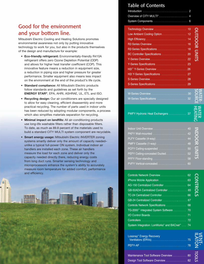
Table of ContentsIntroduction . . . . . . . . . . . . . . . . . . . . . . . . . . . . . . . 2Overview of CITY MULTI® . . . . . . . . . . . . . . . . . . . . 4System Components . . . . . . . . . . . . . . . . . . . . . . . . 6
Technology Overview . . . . . . . . . . . . . . . . . . . . . . 10 Low Ambient Cooling Option . . . . . . . . . . . . . . . . . 12 High Efficiency . . . . . . . . . . . . . . . . . . . . . . . . . . . . 14 R2-Series Overview . . . . . . . . . . . . . . . . . . . . . . . . 16R2-Series Specifications . . . . . . . . . . . . . . . . . . . . 18BC Controller Specifications . . . . . . . . . . . . . . . . . 20Y-Series Overview . . . . . . . . . . . . . . . . . . . . . . . . . 22Y-Series Specifications . . . . . . . . . . . . . . . . . . . . . 23 H2i™ Y-Series Overview . . . . . . . . . . . . . . . . . . . . 26H2i Y-Series Specifications . . . . . . . . . . . . . . . . . 27S-Series Overview . . . . . . . . . . . . . . . . . . . . . . . . . 28S-Series Specifications . . . . . . . . . . . . . . . . . . . . . 29
W-Series Overview . . . . . . . . . . . . . . . . . . . . . . . . 30W-Series Specifications . . . . . . . . . . . . . . . . . . . . 32
PWFY Hydronic Heat Exchangers . . . . . . . . . . . . 37
Indoor Unit Overview . . . . . . . . . . . . . . . . . . . . . . . 40 PKFY Wall-mounted . . . . . . . . . . . . . . . . . . . . . . . 42 PLFY Cassette (4-way) . . . . . . . . . . . . . . . . . . . . . 44 PMFY Cassette (1-way) . . . . . . . . . . . . . . . . . . . . 48 PCFY Ceiling-suspended . . . . . . . . . . . . . . . . . . . 50 PEFY Ceiling-concealed Ducted . . . . . . . . . . . . . . 52 PFFY Floor-standing . . . . . . . . . . . . . . . . . . . . . . . 58PVFY Vertical-concealed . . . . . . . . . . . . . . . . . . . . 60
Controls Network Overview . . . . . . . . . . . . . . . . . . 62 iPhone Mobile Application . . . . . . . . . . . . . . . . . . . . 63AG-150 Centralized Controller . . . . . . . . . . . . . . . 64GB-50ADA Centralized Controller . . . . . . . . . . . . . . 65TC-24 Centralized Controller . . . . . . . . . . . . . . . . . 66GB-24 Centralized Controller . . . . . . . . . . . . . . . . . 67 Controls Network Specifications . . . . . . . . . . . . . . 68TG-2000™ Integrated System Software . . . . . . . . . 70I/O Control Boards . . . . . . . . . . . . . . . . . . . . . . . . . 71Controllers . . . . . . . . . . . . . . . . . . . . . . . . . . . . . . . 72System Integration: LonWorks® and BACnet® . . . 74
Lossnay® Energy Recovery Ventilators (ERVs) . . . . . . . . . . . . . . . . . . . . . . . . . 75
PEFY-AF . . . . . . . . . . . . . . . . . . . . . . . . . . . . . . . . 78
Maintenance Tool Software Overview . . . . . . . . . . 80Design Tool Software Overview . . . . . . . . . . . . . . . 82
OU
TDO
OR U
NITS
WATER-
SOU
RCEW
ATER H
EATING
VENT-
ILATON
TOO
LSIN
DO
OR U
NITS
CO
NTRO
LS
Good for the environment and your bottom line.Mitsubishi Electric Cooling and Heating Solutions promotes environmental awareness not only by putting innovative technology to work for you, but also in the products themselves of the design and manufacture for example:
• Eco-friendlyrefrigerant: Environmentally-friendly R410A refrigerant offers zero Ozone Depletion Potential (ODP) and allows for higher heat transfer coefficient (COP). This innovative feature means a reduction in equipment size, a reduction in piping size and higher pressure for greater performance. Smaller equipment also means less impact on the environment at the end of the product’s life cycle.
• Standardcompliance: All Mitsubishi Electric products follow standards and guidelines as set forth by the ENERGYSTAR®, EPA, AHRI, ASHRAE, UL, ETL and ISO.
• Recyclingdesign: Our air conditioners are specially designed to allow for easy cleaning, efficient disassembly and more practical recycling. The number of parts used in indoor units has been reduced by adopting modular components, a process which also simplifies materials separation for recycling.
• Minimalimpactonlandfills:All air-conditioning products use long-life washable filters rather than disposable filters. To date, as much as 89.8 percent of the materials used to build a standard CITY MULTI system component are recyclable.
• Smartenergyusage: Mitsubishi Electric INVERTER zoning systems smartly deliver only the amount of capacity needed–unlike a typical full-power ON system. Individual indoor air handlers are installed each zone. These air handlers measure the load for each zone and deliver only the capacity needed directly there, reducing energy costs from long duct runs. Smarter sensing technology and microprocessors enhance the system’s ability to accurately measure room temperature for added comfort, performance and efficiency.
4
CITY MULTI® VRF (Variable Refrigerant Flow)
Zoning Systems: user-friendly ductless, or ducted commercial or
residential comfort control systems.
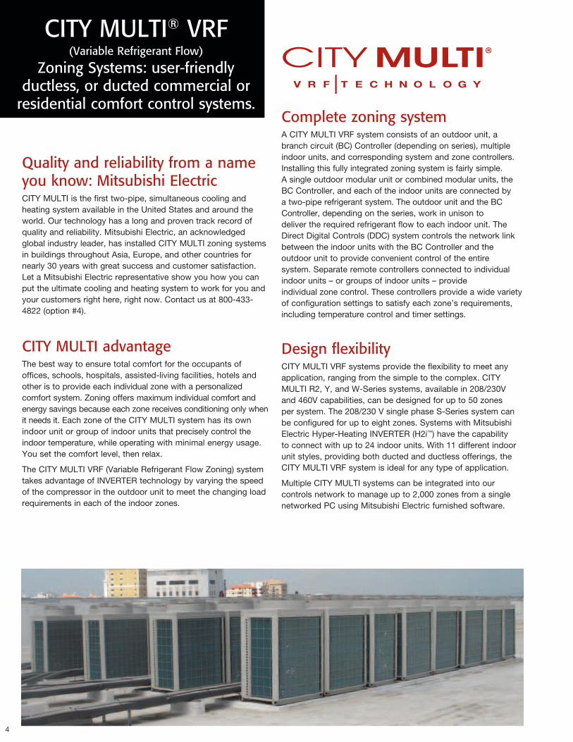
Quality and reliability from a name you know: Mitsubishi ElectricCITY MULTI is the first two-pipe, simultaneous cooling and heating system available in the United States and around the world. Our technology has a long and proven track record of quality and reliability. Mitsubishi Electric, an acknowledged global industry leader, has installed CITY MULTI zoning systems in buildings throughout Asia, Europe, and other countries for nearly 30 years with great success and customer satisfaction. Let a Mitsubishi Electric representative show you how you can put the ultimate cooling and heating system to work for you and your customers right here, right now. Contact us at 800-433-4822 (option #4).
CITY MULTI advantageThe best way to ensure total comfort for the occupants of offices, schools, hospitals, assisted-living facilities, hotels and other is to provide each individual zone with a personalized comfort system. Zoning offers maximum individual comfort and energy savings because each zone receives conditioning only when it needs it. Each zone of the CITY MULTI system has its own indoor unit or group of indoor units that precisely control the indoor temperature, while operating with minimal energy usage. You set the comfort level, then relax.
The CITY MULTI VRF (Variable Refrigerant Flow Zoning) system takes advantage of INVERTER technology by varying the speed of the compressor in the outdoor unit to meet the changing load requirements in each of the indoor zones.
Complete zoning systemA CITY MULTI VRF system consists of an outdoor unit, a branch circuit (BC) Controller (depending on series), multiple indoor units, and corresponding system and zone controllers.Installing this fully integrated zoning system is fairly simple. A single outdoor modular unit or combined modular units, the BC Controller, and each of the indoor units are connected by a two-pipe refrigerant system. The outdoor unit and the BC Controller, depending on the series, work in unison to deliver the required refrigerant flow to each indoor unit. The Direct Digital Controls (DDC) system controls the network link between the indoor units with the BC Controller and the outdoor unit to provide convenient control of the entire system. Separate remote controllers connected to individual indoor units – or groups of indoor units – provide individual zone control. These controllers provide a wide variety of configuration settings to satisfy each zone’s requirements, including temperature control and timer settings.
Design flexibility CITY MULTI VRF systems provide the flexibility to meet any application, ranging from the simple to the complex. CITY MULTI R2, Y, and W-Series systems, available in 208/230V and 460V capabilities, can be designed for up to 50 zones per system. The 208/230 V single phase S-Series system can be configured for up to eight zones. Systems with Mitsubishi Electric Hyper-Heating INVERTER (H2i™) have the capability to connect with up to 24 indoor units. With 11 different indoor unit styles, providing both ducted and ductless offerings, the CITY MULTI VRF system is ideal for any type of application.
Multiple CITY MULTI systems can be integrated into our controls network to manage up to 2,000 zones from a single networked PC using Mitsubishi Electric furnished software.
5
Easy to install, easier to operateCITY MULTI is a simple, two-pipe system with easy, non-polar, two-wire control connections. Because of the modular outdoor unit’s compact design, transportation can be transported through a standard, six-person elevator during the building process. This translates into less labor and materials, quicker, easier installation, and a much lower overall operating cost for the building owner.
SustainableThe CITY MULTI technology is designed to allow building owners and designers as many opportunities as possible to attain Leadership in Energy and Environmental Design (LEED®) points when designing and applying CITY MULTI. Mitsubishi Electric is a corporate member of U.S. Green Building Council (USGBC) and is committed to sustainable products and design. CITY MULTI VRF technology may contribute to a building receiving LEED points in areas of Energy and Atmosphere and Indoor Air Quality.
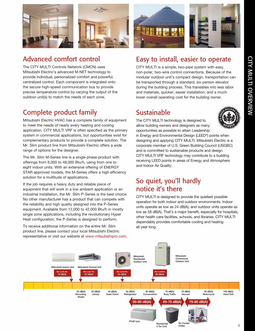
So quiet, you’ll hardly notice it’s thereCITY MULTI is designed to provide the quietest possible operation for both indoor and outdoor environments. Indoor units operate as low as 24 dB(A), and outdoor units operate as low as 58 dB(A). That’s a major benefit, especially for hospitals, other health care facilities, schools, and libraries. CITY MULTI dependably provides comfortable cooling and heating all year long.
Advanced comfort controlThe CITY MULTI Controls Network (CMCN) uses Mitsubishi Electric’s advanced M-NET technology to provide individual, personalized comfort and powerful, centralized control. Each component is integrated onto the secure high-speed communication bus to provide precise temperature control by varying the output of the outdoor unit(s) to match the needs of each zone.
Complete product familyMitsubishi Electric HVAC has a complete family of equipment to meet the needs of nearly every heating and cooling application. CITY MULTI VRF is often specified as the primary system in commercial applications, but opportunities exist for complementary products to provide a complete solution. The Mr. Slim product line from Mitsubishi Electric offers a wide range of options for the designer.
The Mr. Slim M-Series line is a single phase product with offerings from 6,000 to 48,000 Btu/h, using from one to eight indoor units. With an extensive offering of ENERGY STAR approved models, the M-Series offers a high efficiency solution for a multitude of applications.
If the job requires a heavy duty and reliable piece of equipment that will work in a low ambient application or an industrial installation, the Mr. Slim P-Series is the best choice. No other manufacturer has a product that can compete with the reliability and high quality designed into the P-Series equipment. Available from 12,000 to 42,000 Btu/h in mostly single zone applications, including the revolutionary Hyper Heat configuration, the P-Series is designed to perform.
To receive additional information on the entire Mr. Slim product line, please contact your local Mitsubishi Electric representative or visit our website at www.mitsubishipro.com.
50-60 dB(A)
25 dB(A)Recording
Studio
Mitsubishi Indoor Unit Mitsubishi Ducted Unit
Mitsubishi Residential Outdoor Unit
PTHP UnitResidential 3 Ton Unit
Air CooledChiller
Mitsubishi Commercial Outdoor Unit
As Low As 23 dB(A)
As Low As 46 dB(A)
As LowAs 58 dB(A)
33 dB(A)Library
40 dB(A)Quiet Home
50 dB(A)Refrigerator
60 dB(A)Conversation
70 dB(A)Busy Traffic
78 dB(A)Vacuum
90 dB(A)Motorcycle
100 dB(A)Hand Drill
65-75 dB(A) 75-85 dB(A)
As Low As 19 dB(A)
CITY M
ULTI O
VERVIEW
6
OUTDOOR UNITS
CITY MULTI® System Components
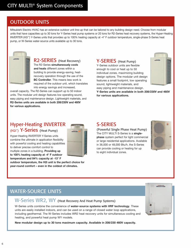
Mitsubishi Electric HVAC has an extensive outdoor unit line-up that can be tailored to any building design need. Choose from modular units that have capacities up to 30 tons for Y-Series heat pump systems or 20 tons for R2-Series heat recovery systems, the Hyper-Heating INVERTER (H2i™) Y-Series units that provides up to 100% heating capacity at -4° F outdoor temperature, single-phase S-Series heat pump, or W-Series water-source units available up to 30 tons.
R2-SERIES (Heat Recovery) The R2-Series simultaneouslycoolsandheats different zones within a building to provide energy-saving, heat- recovery operation through the use of the BCController. This means less work is required of the outdoor unit, which translates into energy savings and increased,
overall capacity. The R2-Series can support up to 50 indoor units. The modular unit design features low operating sound, easy piping and maintenance design. Lightweight materials, and R2-Seriesunitsareavailableinboth208/230Vand460Vforvariousapplications.
Y-SERIES (Heat Pump)Y-Series outdoor units are flexible enough to cool or heat up to 50 individual zones, maximizing building design options. The modular unit design features a small footprint, low operating sound, lightweight materials, and easy piping and maintenance design. Y-Seriesunitsareavailableinboth208/230Vand460Vforvariousapplications.
W-Series WR2, WY (Heat Recovery And Heat Pump Systems)
W-Series units combine the convenience of water-sourcesystemswithVRFtechnology. These units are easily installed indoors, and can be used on a range of closed water loop applications, including geothermal. The W-Series includes WR2 heat recovery units for simultaneous cooling and heating, and powerful heat pump WY models.
Newmodulardesignupto30tonsmaximumcapacity.Availablein208/230460Vcapacity.
S-SERIES (Powerful Single Phase Heat Pump)The CITY MULTI S-Series is a single-phase system perfect for light commercial or large residential applications. Available in 36,000 or 48,000 Btu/h, the S-Series can provide cooling or heating for up to eight individual zones.
Hyper-Heating INVERTER (H2i™) Y-Series (Heat Pump)
Hyper-Heating INVERTER Y-Series units combine the ultimate in application flexibility with powerful cooling and heating capabilities to deliver precise comfort control to multiple zones in a building. Providingupto100%heatingcapacityat-4°Foutdoortemperatureand84%capacityat-13°Foutdoortemperature,theH2iunitistheperfectchoiceforyear-roundcomfort–eveninthecoldestofclimates.
WATER-SOURCE UNITS
7
CONTROLS NETWORK
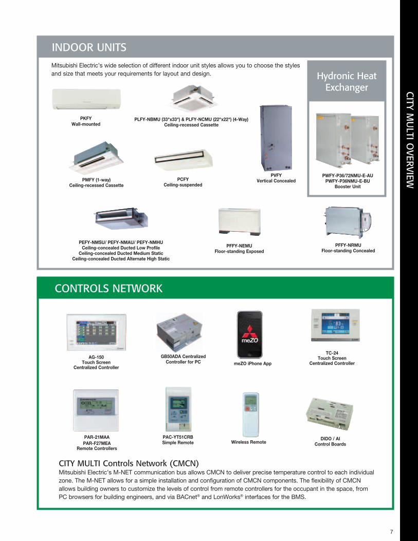
CITY MULTI Controls Network (CMCN) Mitsubishi Electric’s M-NET communication bus allows CMCN to deliver precise temperature control to each individual zone. The M-NET allows for a simple installation and configuration of CMCN components. The flexibility of CMCN allows building owners to customize the levels of control from remote controllers for the occupant in the space, from PC browsers for building engineers, and via BACnet® and LonWorks® interfaces for the BMS.
Mitsubishi Electric’s wide selection of different indoor unit styles allows you to choose the styles and size that meets your requirements for layout and design.
PAR-21MAAPAR-F27MEA
RemoteControllers
AG-150TouchScreen
CentralizedController
GB50ADACentralizedControllerforPC meZOiPhoneApp
PLFY-NBMU(33"x33")&PLFY-NCMU(22"x22")(4-Way)Ceiling-recessedCassette
PFFY-NEMUFloor-standingExposed
PVFYVerticalConcealed
PFFY-NRMUFloor-standingConcealed
PKFYWall-mounted
PEFY-NMSU/PEFY-NMAU/PEFY-NMHUCeiling-concealedDuctedLowProfile
Ceiling-concealedDuctedMediumStaticCeiling-concealedDuctedAlternateHighStatic
PCFYCeiling-suspended
PMFY(1-way)Ceiling-recessedCassette
PAC-YT51CRBSimpleRemote WirelessRemote
DIDO/AIControlBoards
TC-24TouchScreen
CentralizedController
INDOOR UNITS
Hydronic Heat Exchanger
PWFY-P36/72NMU-E-AUPWFY-P36NMU-E-BU
BoosterUnit
CITY M
ULTI O
VERVIEW
PURY-P72TJMU-A
PUHY-P72TJMU-A
PUHY-P72TJMU-A
8
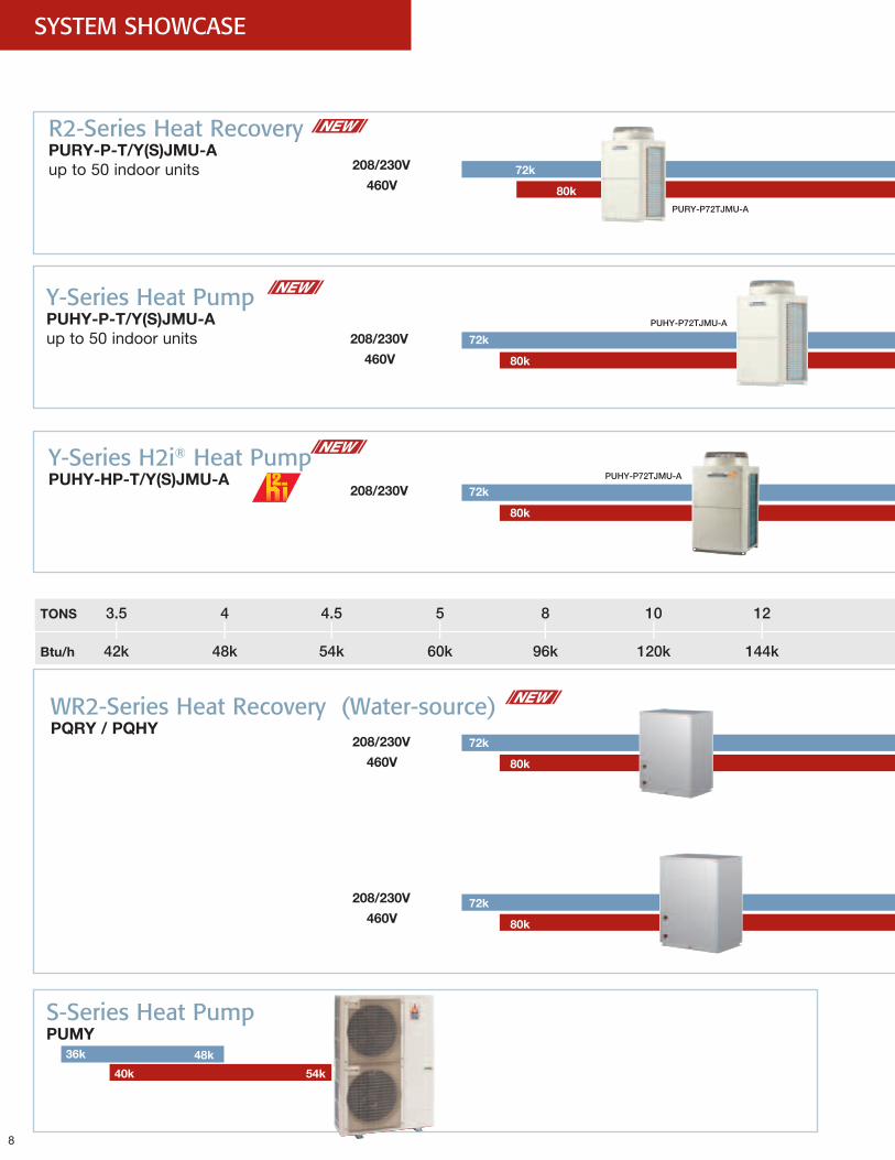
TONS 3.5 4 4.5 5 8 10 12 16 20 24 26 30 TONS I I I I I I I I I I I I Btu/h 42k 48k 54k 60k 96k 120k 144k 192k 240k 288k 312k 360k Btu/h
Y-Series H2i® Heat PumpPUHY-HP-T/Y(S)JMU-A
WR2-Series Heat Recovery (Water-source)PQRY/PQHY
R2-Series Heat RecoveryPURY-P-T/Y(S)JMU-Aup to 50 indoor units
Y-Series Heat Pump PUHY-P-T/Y(S)JMU-Aup to 50 indoor units
208/230V
208/230V
208/230V
208/230V
208/230V
460V
460V
460V
460V
SYSTEM SHOWCASE
S-Series Heat PumpPUMY
72k
72k
72k
72k
36k 48k
80k
80k
80k
80k
80k
40k 54k
72k

PUHY-P96TJMU-A PUHY-P120TJMU-A
PURY-P96TJMU-A PURY-P240TJMU-A
9
TONS 3.5 4 4.5 5 8 10 12 16 20 24 26 30 TONS I I I I I I I I I I I I Btu/h 42k 48k 54k 60k 96k 120k 144k 192k 240k 288k 312k 360k Btu/h
288k
360k
240k
360k
320k
403k
216k
270k
405k
Cooling
Heating
192k
SYSTEM C
OM
PON
ENTS
10
CITY MULTI Revit® ObjectsAutodesk® Revit® building information modeling (BIM) software is helping engineers, architects, and construction professionals explore early design concepts and forms and more accurately maintain a vision through design, documentation, and construction. In mid-2009, Revit “objects” for Mitsubishi CITY MULTI systems were made available on Autodesk® Seek, The SmartBIM Library from Reed Construction Data and on Mitsubishi’s Website. The complete outdoor unit and indoor unit lineup are available for download. As use of Revit and the Mitsubishi product offering continues to grow, look for upcoming announcements regarding additional Revit objects.
Larger projects, more optionsThe modular outdoor unit design offers the option for either a 208/230V, 3-Phase, 60Hz power source or a or a 460V, 3-Phase, 60Hz power source. Another feature is the larger capacities for the larger projects–up to 30 tons on select systems–and up to 50 an increased number of connectable indoor units with increased line lengths. These capabilities increase the range of applications for which an architect, engineer or building owner can specify.
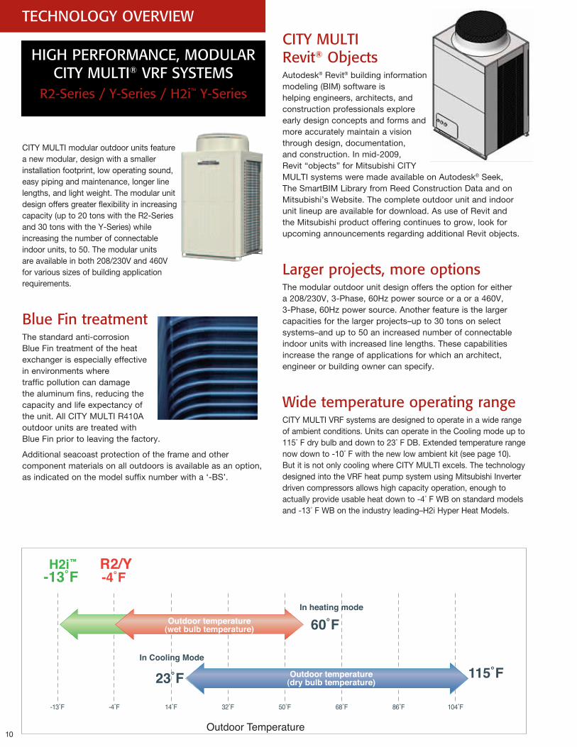
Wide temperature operating rangeCITY MULTI VRF systems are designed to operate in a wide range of ambient conditions. Units can operate in the Cooling mode up to 115° F dry bulb and down to 23° F DB. Extended temperature range now down to -10° F with the new low ambient kit (see page 10). But it is not only cooling where CITY MULTI excels. The technology designed into the VRF heat pump system using Mitsubishi Inverter driven compressors allows high capacity operation, enough to actually provide usable heat down to -4° F WB on standard models and -13° F WB on the industry leading–H2i Hyper Heat Models.
TECHNOLOGY OVERVIEW
HIGH PERFORMANCE, MODULAR CITY MULTI® VRF SYSTEMS
R2-Series / Y-Series / H2i™ Y-Series
CITY MULTI modular outdoor units feature a new modular, design with a smaller installation footprint, low operating sound, easy piping and maintenance, longer line lengths, and light weight. The modular unit design offers greater flexibility in increasing capacity (up to 20 tons with the R2-Series and 30 tons with the Y-Series) while increasing the number of connectable indoor units, to 50. The modular units are available in both 208/230V and 460V for various sizes of building application requirements.
Blue Fin treatmentThe standard anti-corrosion Blue Fin treatment of the heat exchanger is especially effective in environments where traffic pollution can damage the aluminum fins, reducing the capacity and life expectancy of the unit. All CITY MULTI R410A outdoor units are treated with Blue Fin prior to leaving the factory.
Additional seacoast protection of the frame and other component materials on all outdoors is available as an option, as indicated on the model suffix number with a ‘-BS’.
-4˚F-13˚F 14˚F 32˚F 50˚F 68˚F 86˚F 104˚F
In Cooling Mode
Outdoor temperature(dry bulb temperature)
-4˚FR2/Y
-13˚FH2i™
60˚FIn heating mode
23˚F 115˚F
Outdoor Temperature
Outdoor temperature(wet bulb temperature)
11
100%
4%
15Hz Cooling:18-75HzHeating:15-88Hz
Heating / Cooling Capacity
Linear CapacityControl
Compressor Frequency* image
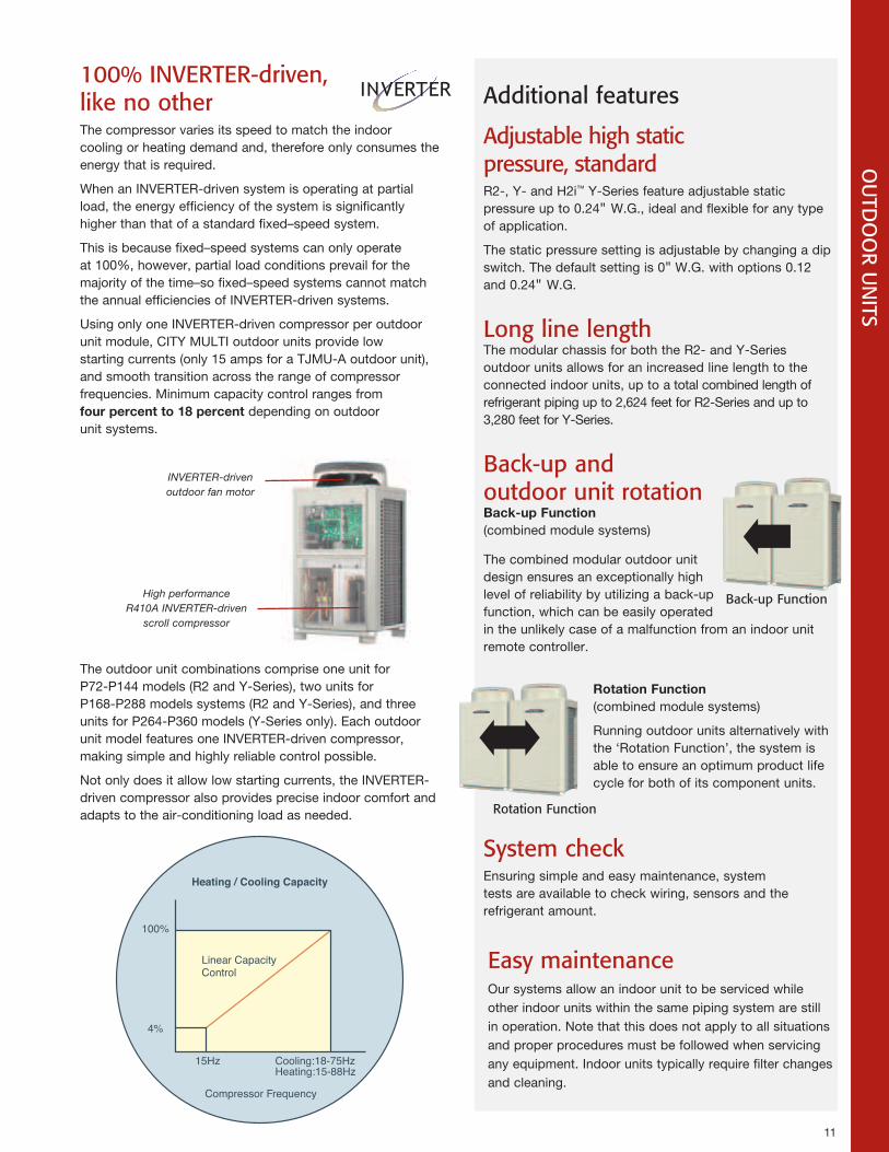
100% INVERTER-driven, like no otherThe compressor varies its speed to match the indoor cooling or heating demand and, therefore only consumes the energy that is required.
When an INVERTER-driven system is operating at partial load, the energy efficiency of the system is significantly higher than that of a standard fixed–speed system.
This is because fixed–speed systems can only operate at 100%, however, partial load conditions prevail for the majority of the time–so fixed–speed systems cannot match the annual efficiencies of INVERTER-driven systems.
Using only one INVERTER-driven compressor per outdoor unit module, CITY MULTI outdoor units provide low starting currents (only 15 amps for a TJMU-A outdoor unit), and smooth transition across the range of compressor frequencies. Minimum capacity control ranges from fourpercentto18percent depending on outdoor unit systems.
The outdoor unit combinations comprise one unit for P72-P144 models (R2 and Y-Series), two units for P168-P288 models systems (R2 and Y-Series), and three units for P264-P360 models (Y-Series only). Each outdoor unit model features one INVERTER-driven compressor, making simple and highly reliable control possible.
Not only does it allow low starting currents, the INVERTER-driven compressor also provides precise indoor comfort and adapts to the air-conditioning load as needed.
INVERTER-driven outdoor fan motor
High performance R410A INVERTER-driven
scroll compressor
Additional features
Adjustable high static pressure, standardR2-, Y- and H2i™ Y-Series feature adjustable static pressure up to 0.24" W.G., ideal and flexible for any type of application.
The static pressure setting is adjustable by changing a dip switch. The default setting is 0" W.G. with options 0.12 and 0.24" W.G.
Long line length The modular chassis for both the R2- and Y-Series outdoor units allows for an increased line length to the connected indoor units, up to a total combined length of refrigerant piping up to 2,624 feet for R2-Series and up to 3,280 feet for Y-Series.
Back-up and outdoor unit rotation Back-upFunction (combined module systems)
The combined modular outdoor unit design ensures an exceptionally high level of reliability by utilizing a back-up function, which can be easily operated in the unlikely case of a malfunction from an indoor unit remote controller.
RotationFunction (combined module systems)
Running outdoor units alternatively with the ‘Rotation Function’, the system is able to ensure an optimum product life cycle for both of its component units.
System checkEnsuring simple and easy maintenance, system tests are available to check wiring, sensors and the refrigerant amount.
Easy maintenanceOur systems allow an indoor unit to be serviced while other indoor units within the same piping system are still in operation. Note that this does not apply to all situations and proper procedures must be followed when servicing any equipment. Indoor units typically require filter changes and cleaning.
OU
TDO
OR U
NITS
Back-up Function
Rotation Function
12
LOW AMBIENT COOLING OPTION
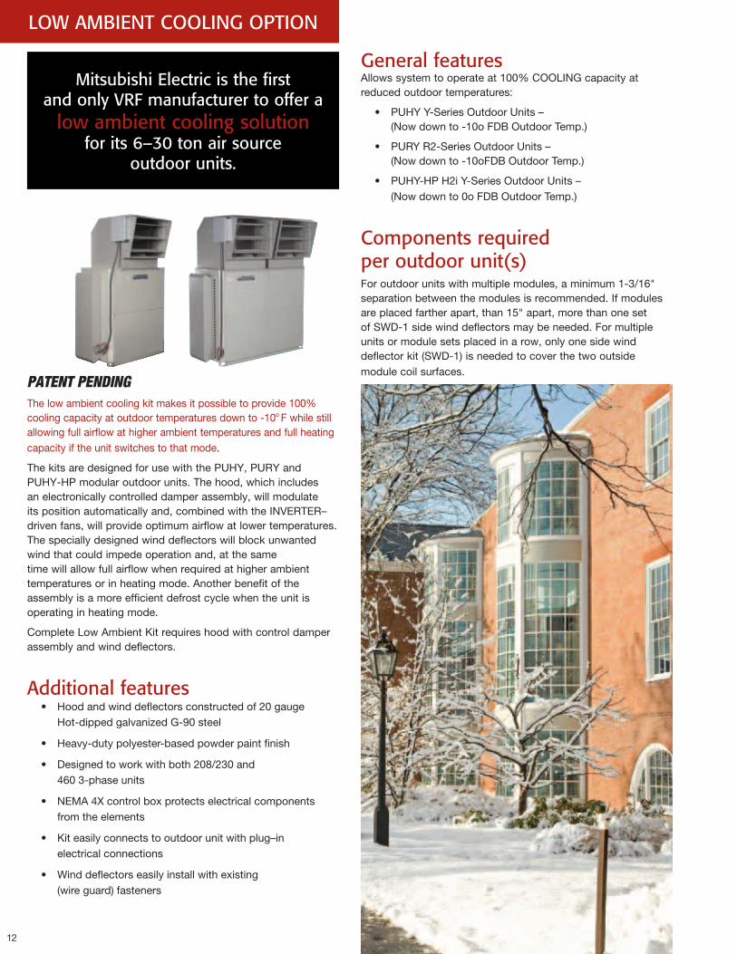
PATENT PENDINGThe low ambient cooling kit makes it possible to provide 100% cooling capacity at outdoor temperatures down to -10o F while still allowing full airflow at higher ambient temperatures and full heating capacity if the unit switches to that mode.
The kits are designed for use with the PUHY, PURY and PUHY-HP modular outdoor units. The hood, which includes an electronically controlled damper assembly, will modulate its position automatically and, combined with the INVERTER– driven fans, will provide optimum airflow at lower temperatures. The specially designed wind deflectors will block unwanted wind that could impede operation and, at the same time will allow full airflow when required at higher ambient temperatures or in heating mode. Another benefit of the assembly is a more efficient defrost cycle when the unit is operating in heating mode.
Complete Low Ambient Kit requires hood with control damper assembly and wind deflectors.
Additional features• Hood and wind deflectors constructed of 20 gauge
Hot-dipped galvanized G-90 steel
• Heavy-duty polyester-based powder paint finish
• Designed to work with both 208/230 and 460 3-phase units
• NEMA 4X control box protects electrical components from the elements
• Kit easily connects to outdoor unit with plug–in electrical connections
• Wind deflectors easily install with existing (wire guard) fasteners
Mitsubishi Electric is the first and only VRF manufacturer to offer a
low ambient cooling solution for its 6–30 ton air source
outdoor units.
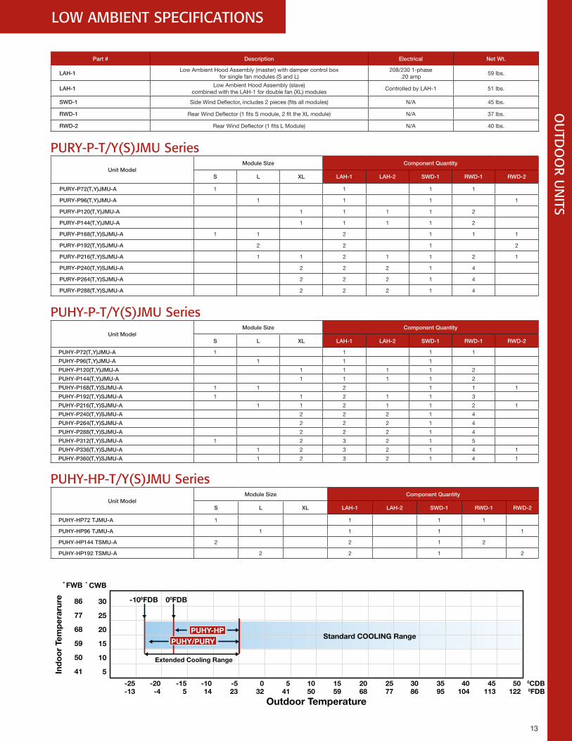
General features Allows system to operate at 100% COOLING capacity at reduced outdoor temperatures:
• PUHY Y-Series Outdoor Units – (Now down to -10o FDB Outdoor Temp.)
• PURY R2-Series Outdoor Units – (Now down to -10oFDB Outdoor Temp.)
• PUHY-HP H2i Y-Series Outdoor Units – (Now down to 0o FDB Outdoor Temp.)
Components required per outdoor unit(s) For outdoor units with multiple modules, a minimum 1-3/16" separation between the modules is recommended. If modules are placed farther apart, than 15" apart, more than one set of SWD-1 side wind deflectors may be needed. For multiple units or module sets placed in a row, only one side wind deflector kit (SWD-1) is needed to cover the two outside module coil surfaces.
13
LOW AMBIENT SPECIFICATIONS
PUHY-HP
Outdoor Temperature
Extended Cooling Range
Ind
oo
r Te
mp
erar
ure
Standard COOLING Range
° FWB
86
77
68
59
50
41
° CWB
30
25
20
15
10
5
-100FDB 00FDB
-25 -20 -15 -10 -5 0 5 10 15 20 25 30 35 40 45 50 0CDB-13 -4 5 14 23 32 41 50 59 68 77 86 95 104 113 122 0FDB
PUHY/PURY
OU
TDO
OR U
NITS
Part # Description Electrical Net Wt.
LAH-1Low Ambient Hood Assembly (master) with damper control box
for single fan modules (S and L)208/230 1-phase
.20 amp59 lbs.
LAH-1Low Ambient Hood Assembly (slave)
combined with the LAH-1 for double fan (XL) modulesControlled by LAH-1 51 lbs.
SWD-1 Side Wind Deflector, includes 2 pieces (fits all modules) N/A 45 lbs.
RWD-1 Rear Wind Deflector (1 fits S module, 2 fit the XL module) N/A 37 lbs.
RWD-2 Rear Wind Deflector (1 fits L Module) N/A 40 lbs.
PURY-P-T/Y(S)JMU SeriesUnit Model
Module Size Component Quantity
S L XL LAH-1 LAH-2 SWD-1 RWD-1 RWD-2
PURY-P72(T,Y)JMU-A 1 1 1 1
PURY-P96(T,Y)JMU-A 1 1 1 1
PURY-P120(T,Y)JMU-A 1 1 1 1 2
PURY-P144(T,Y)JMU-A 1 1 1 1 2
PURY-P168(T,Y)SJMU-A 1 1 2 1 1 1
PURY-P192(T,Y)SJMU-A 2 2 1 2
PURY-P216(T,Y)SJMU-A 1 1 2 1 1 2 1
PURY-P240(T,Y)SJMU-A 2 2 2 1 4
PURY-P264(T,Y)SJMU-A 2 2 2 1 4
PURY-P288(T,Y)SJMU-A 2 2 2 1 4
PUHY-P-T/Y(S)JMU SeriesUnit Model
Module Size Component Quantity
S L XL LAH-1 LAH-2 SWD-1 RWD-1 RWD-2
PUHY-P72(T,Y)JMU-A 1 1 1 1
PUHY-P96(T,Y)JMU-A 1 1 1
PUHY-P120(T,Y)JMU-A 1 1 1 1 2
PUHY-P144(T,Y)JMU-A 1 1 1 1 2
PUHY-P168(T,Y)SJMU-A 1 1 2 1 1 1
PUHY-P192(T,Y)SJMU-A 1 1 2 1 1 3
PUHY-P216(T,Y)SJMU-A 1 1 2 1 1 2 1
PUHY-P240(T,Y)SJMU-A 2 2 2 1 4
PUHY-P264(T,Y)SJMU-A 2 2 2 1 4
PUHY-P288(T,Y)SJMU-A 2 2 2 1 4
PUHY-P312(T,Y)SJMU-A 1 2 3 2 1 5
PUHY-P336(T,Y)SJMU-A 1 2 3 2 1 4 1
PUHY-P360(T,Y)SJMU-A 1 2 3 2 1 4 1
PUHY-HP-T/Y(S)JMU SeriesUnit Model
Module Size Component Quantity
S L XL LAH-1 LAH-2 SWD-1 RWD-1 RWD-2
PUHY-HP72 TJMU-A 1 1 1 1
PUHY-HP96 TJMU-A 1 1 1 1
PUHY-HP144 TSMU-A 2 2 1 2
PUHY-HP192 TSMU-A 2 2 1 2
14
FPO IMAGE TO COME
Leading the VRF industryMitsubishi Electric HVAC has been at the forefront of the charge to develop proper testing standards and procedures for VRF systems, providing clients the necessary information to properly incorporate these systems into their building designs.
AHRI StandardsAir-conditioning, Heating and Refrigeration Institute (AHRI) Standards 210/240 and 340/360 had been used as the benchmark for establishing the testing methods of traditional unitary HVAC equipment. These standards have formalized the use of such terms as EER, IPLV, COP, SEER, and HSPF– terms which are recognized and applied throughout the HVAC industry today. The simple testing procedures detailed in these existing AHRI standards, however, were not adequate to appropriately measure efficiency levels within advanced VRF systems, and could not account for such technologies as inverter-driven compressors, simultaneous cooling and heating, and variable-capacity ductless and ducted indoor units.
AHRI Standard 1230Mitsubishi Electric worked with the Department of Energy (DOE) and AHRI to gain regulatory acceptance for VRF systems. Initially, Mitsubishi Electric requested DOE grant waivers from the existing testing standards for VRF systems. It was quickly recognized that waivers weren’t a long-term solution, and Mitsubishi Electric immediately assisted in developing a proper testing standard for VRF systems–a standard that is now known as AHRI Standard 1230.
Mitsubishi Electric HVAC continues to drive acceptance of VRF technology in the U.S. engineering and regulatory
arenas.
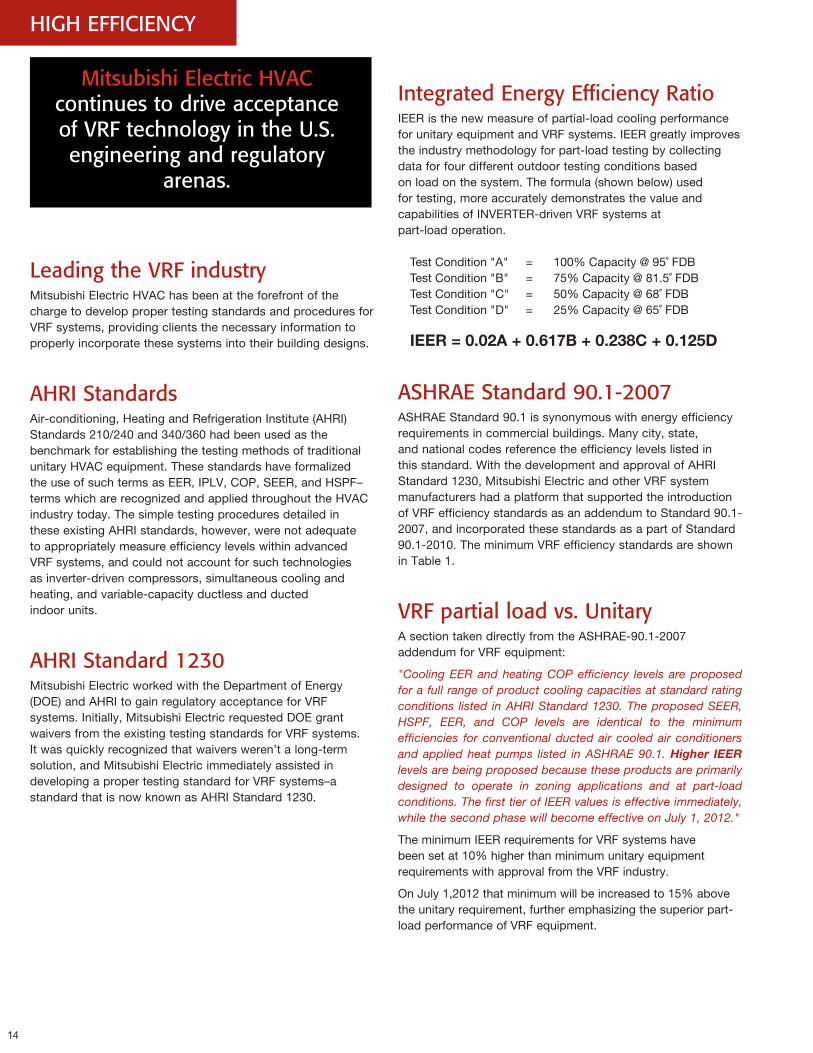
Integrated Energy Efficiency RatioIEER is the new measure of partial-load cooling performance for unitary equipment and VRF systems. IEER greatly improves the industry methodology for part-load testing by collecting data for four different outdoor testing conditions based on load on the system. The formula (shown below) used for testing, more accurately demonstrates the value and capabilities of INVERTER-driven VRF systems at part-load operation.
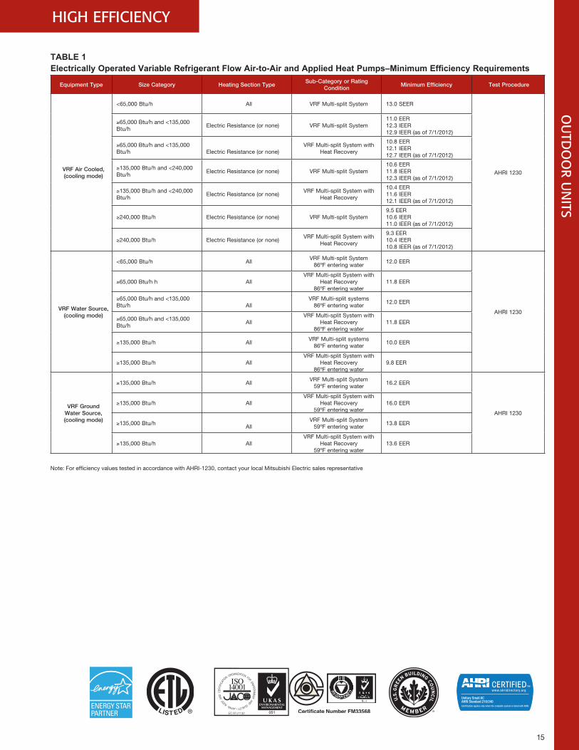
ASHRAE Standard 90.1-2007 ASHRAE Standard 90.1 is synonymous with energy efficiency requirements in commercial buildings. Many city, state, and national codes reference the efficiency levels listed in this standard. With the development and approval of AHRI Standard 1230, Mitsubishi Electric and other VRF system manufacturers had a platform that supported the introduction of VRF efficiency standards as an addendum to Standard 90.1-2007, and incorporated these standards as a part of Standard 90.1-2010. The minimum VRF efficiency standards are shown in Table 1.
VRF partial load vs. UnitaryA section taken directly from the ASHRAE-90.1-2007 addendum for VRF equipment:
"Cooling EER and heating COP efficiency levels are proposed for a full range of product cooling capacities at standard rating conditions listed in AHRI Standard 1230. The proposed SEER, HSPF, EER, and COP levels are identical to the minimum efficiencies for conventional ducted air cooled air conditioners and applied heat pumps listed in ASHRAE 90.1. Higher IEERlevels are being proposed because these products are primarily designed to operate in zoning applications and at part-load conditions. The first tier of IEER values is effective immediately, while the second phase will become effective on July 1, 2012."
The minimum IEER requirements for VRF systems have been set at 10% higher than minimum unitary equipment requirements with approval from the VRF industry.
On July 1,2012 that minimum will be increased to 15% above the unitary requirement, further emphasizing the superior part-load performance of VRF equipment.
HIGH EFFICIENCY
Test Condition "A" = 100% Capacity @ 95˚ FDBTest Condition "B" = 75% Capacity @ 81.5˚ FDBTest Condition "C" = 50% Capacity @ 68˚ FDBTest Condition "D" = 25% Capacity @ 65˚ FDB
IEER=0.02A+0.617B+0.238C+0.125D
15
HIGH EFFICIENCY
TABLE 1Electrically Operated Variable Refrigerant Flow Air-to-Air and Applied Heat Pumps–Minimum Efficiency Requirements
Equipment Type Size Category Heating Section TypeSub-Category or Rating
ConditionMinimum Efficiency Test Procedure
VRF Air Cooled,(cooling mode)
<65,000 Btu/h All VRF Multi-split System 13.0 SEER
AHRI 1230
≥65,000 Btu/h and <135,000 Btu/h
Electric Resistance (or none) VRF Multi-split System11.0 EER12.3 IEER 12.9 IEER (as of 7/1/2012)
≥65,000 Btu/h and <135,000 Btu/h Electric Resistance (or none)
VRF Multi-split System with Heat Recovery
10.8 EER12.1 IEER 12.7 IEER (as of 7/1/2012)
≥135,000 Btu/h and <240,000 Btu/h
Electric Resistance (or none) VRF Multi-split System10.6 EER11.8 IEER 12.3 IEER (as of 7/1/2012)
≥135,000 Btu/h and <240,000 Btu/h
Electric Resistance (or none)VRF Multi-split System with
Heat Recovery
10.4 EER11.6 IEER 12.1 IEER (as of 7/1/2012)
≥240,000 Btu/h Electric Resistance (or none) VRF Multi-split System9.5 EER10.6 IEER11.0 IEER (as of 7/1/2012)
≥240,000 Btu/h Electric Resistance (or none)VRF Multi-split System with
Heat Recovery
9.3 EER10.4 IEER10.8 IEER (as of 7/1/2012)
VRF Water Source,(cooling mode)
<65,000 Btu/h AllVRF Multi-split System
86ºF entering water12.0 EER
AHRI 1230
≥65,000 Btu/h h AllVRF Multi-split System with
Heat Recovery86ºF entering water
11.8 EER
≥65,000 Btu/h and <135,000 Btu/h All
VRF Multi-split systems86ºF entering water
12.0 EER
≥65,000 Btu/h and <135,000 Btu/h
AllVRF Multi-split System with
Heat Recovery 86ºF entering water
11.8 EER
≥135,000 Btu/h AllVRF Multi-split systems
86ºF entering water10.0 EER
≥135,000 Btu/h AllVRF Multi-split System with
Heat Recovery86ºF entering water
9.8 EER
VRF Ground Water Source,(cooling mode)
≥135,000 Btu/h AllVRF Multi-split System
59ºF entering water16.2 EER
AHRI 1230
≥135,000 Btu/h AllVRF Multi-split System with
Heat Recovery59ºF entering water
16.0 EER
≥135,000 Btu/hAll
VRF Multi-split System 59ºF entering water
13.8 EER
≥135,000 Btu/h AllVRF Multi-split System with
Heat Recovery59ºF entering water
13.6 EER
Note: For efficiency values tested in accordance with AHRI-1230, contact your local Mitsubishi Electric sales representative
OU
TDO
OR U
NITS
16
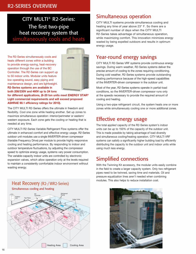
The R2-Series simultaneously cools and heats different zones within a building to provide energy-saving, heat-recovery operation through the use of the BC Controller. The R2-Series can support up to 50 indoor units. Modular units feature low operating sound, easy piping and maintenance design, and are lightweight. R2-Seriessystemsareavailableinboth208/230Vand460Vupto24tonsfordifferentapplications,(6-20tonunitsmeetENERGYSTAR®LightcommercialrequirementsandwillexceedproposedASHRAE90.1efficiencyratingsfor2010).
The CITY MULTI R2-Series offers the ultimate in freedom and flexibility. Cool one zone while heating another. Set up zones to maximize simultaneous operation: interior/perimeter or eastern/western exposure. Each zone gets the cooling or heating that is needed at any time.
CITY MULTI R2-Series Variable Refrigerant Flow systems offer the ultimate in enhanced comfort and effective energy usage. R2-Series outdoor unit modules use a single INVERTER-driven compressor (Variable Frequency Drive) per module to provide highly responsive cooling and heating performance. By responding to indoor and outdoor temperature fluctuations, by adjusting the compressor speed to optimize energy usage, systems vary power consumption. The variable-capacity indoor units are controlled by electronic expansion valves, which allow operation only at the levels required to maintain a consistently comfortable indoor environment without wasting energy.
Simultaneous operationCITY MULTI systems provide simultaneous cooling and heating any time of year above 23° F. So there are a significant number of days when the CITY MULTI R2-Series takes advantage of simultaneous operation, while maximizing comfort. This innovation minimizes energy wasted by being expelled outdoors and results in optimum energy usage.
Year-round energy savingsCITY MULTI R2-Series VRF systems provide continuous energy savings. During warm weather, R2-Series systems deliver the precise amount of cooling to the zones requiring conditioning. During cold weather, R2-Series systems provide outstanding heating performance because of the high-speed capabilities of the INVERTER-driven compressor in the outdoor unit.
Most of the year, R2-Series systems operate in partial-load conditions, so the INVERTER-driven compressor runs only at the speeds necessary to provide the required amount of cooling and heating.
Using a two-pipe refrigerant circuit, the system heats one or more zones while simultaneously cooling one or more additional zones.
Effective energy usageThe total applied capacity of the R2-Series system’s indoor units can be up to 150% of the capacity of the outdoor unit. This is made possible by taking advantage of load diversity and simultaneous cooling/heating operation. CITY MULTI VRF systems can satisfy a significantly higher building load by efficiently distributing the capacity to the outdoor unit and indoor units while using much less energy.
Simplified connectionsWith the Twinning Kit accessory, the modular units easily combine in the field to create a larger capacity system. Only two refrigerant pipes need to be twinned, saving time and materials. Oil and pressure equalization lines aren’t needed when combining modules. This also helps to reduce installation cost.
R2-SERIES OVERVIEW
CITY MULTI® R2-Series: The first two-pipe
heat recovery system that simultaneously cools and heats
Heating Area Cooling Area
Heat Recovery (R2-/ WR2-Series)Simultaneous cooling and heating
17
CITY MULTI Two-Pipe Heat Recovery System
Refrigerant Distribution Units
Indoor Units
OTHER MANUFACTURERS SYSTEM
Outdoor UnitOutdoor Unit BC Controller
17
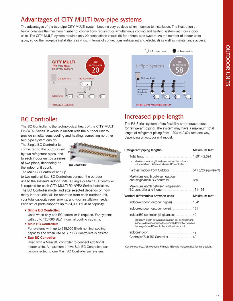
Increased pipe lengthThe R2-Series system offers flexibility and reduced costs for refrigerant piping. The system may have a maximum total length of refrigerant piping from 1,804 to 2,624 feet one way, depending on outdoor unit model.
BC ControllerThe BC Controller is the technological heart of the CITY MULTI R2-/WR2-Series. It works in unison with the outdoor unit to provide simultaneous cooling and heating, something no other two-pipe system can do. The Single BC Controller is connected to the outdoor unit by two refrigerant pipes, and to each indoor unit by a series of two pipes, depending on the indoor unit count. The Main BC Controller and up to two optional Sub BC Controllers connect the outdoor unit to the system’s indoor units. A Single or Main BC Controller is required for each CITY MULTI R2-/WR2-Series installation. The BC Controller model and size selected depends on how many indoor units will be operated from each outdoor unit, your total capacity requirements, and your installation needs. Each set of ports supports up to 54,000 Btu/h of capacity.
• SingleBCController:Used when only one BC controller is required. For systems with up to 120,000 Btu/h nominal cooling capacity.
• MainBCController:For systems with up to 288,000 Btu/h nominal cooling capacity and when use of Sub BC Controllers is desired.
• SubBCController:Used with a Main BC controller to connect additional indoor units. A maximum of two Sub BC Controllers can be connected to one Main BC Controller per system.
BCController
OU
TDO
OR U
NITS
Advantages of CITY MULTI two-pipe systemsThe advantages of the two-pipe CITY MULTI system become very obvious when it comes to installation. The illustration s below compare the minimum number of connections required for simultaneous cooling and heating system with four indoor units. The CITY MULTI system requires only 20 connections versus 58 for a three-pipe system. As the number of indoor units grow, so do the two-pipe installations savings, in terms of connections (refrigerant and electrical) as well as maintenance access.
Refrigerantpipinglengths Maximumfeet
Total length ..........................................................1,804 - 2,624 - Maximum total length is dependent on the outdoor
unit model and distance between BC controller.
Farthest Indoor from Outdoor ............................541 (623 equivalent)
Maximum length between outdoor and single/main BC controller ............................360
Maximum length between single/main BC controller and indoor ...................................131-196
Verticaldifferentialsbetweenunits Maximumfeet
Indoor/outdoor (outdoor higher) .........................164*
Indoor/outdoor (outdoor lower) ..........................131
Indoor/BC controller (single/main) ......................49 - Maximum length between single/main BC controller and
indoor is dependent upon the vertical differential between the single/main BC controller and the indoor unit.
Indoor/indoor .......................................................49 Controller/Sub BC Controller ..............................49
*Can be extended. Ask your local Mitsubishi Electric representative for more details.
18
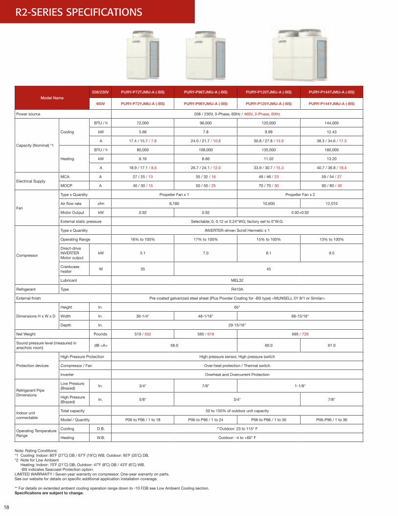
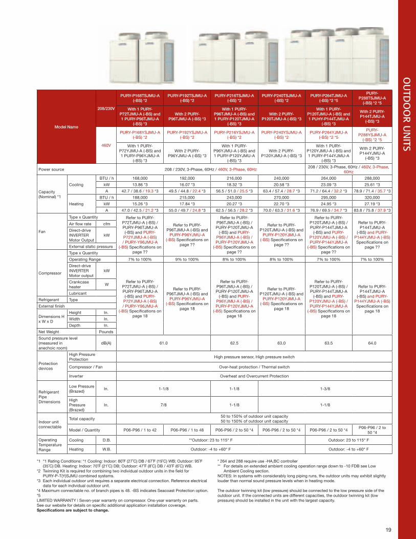
R2-SERIES SPECIFICATIONS
Model Name
208/230V PURY-P72TJMU-A (-BS) PURY-P96TJMU-A (-BS) PURY-P120TJMU-A (-BS) PURY-P144TJMU-A (-BS)
460V PURY-P72YJMU-A (-BS) PURY-P96YJMU-A (-BS) PURY-P120YJMU-A (-BS) PURY-P144YJMU-A (-BS)
Power source 208 / 230V, 3-Phase, 60Hz / 460V, 3-Phase, 60Hz
Capacity (Nominal) *1
Cooling
BTU / h 72,000 96,000 120,000 144,000
kW 5.66 7.8 9.99 12.43
A 17.4 / 15.7 / 7.8 24.0 / 21.7 / 10.8 30.8 / 27.8 / 13.9 38.3 / 34.6 / 17.3
Heating
BTU / h 80,000 108,000 135,000 160,000
kW 6.16 8.66 11.02 13.20
A 18.9 / 17.1 / 8.5 26.7 / 24.1 / 12.0 33.9 / 30.7 / 15.3 40.7 / 36.8 / 18.4
Electrical SupplyMCA A 27 / 25 / 13 35 / 32 / 16 49 / 46 / 23 59 / 54 / 27
MOCP A 40 / 30 / 15 50 / 50 / 25 70 / 70 / 30 90 / 80 / 40
Fan
Type x Quantity Propeller Fan x 1 Propeller Fan x 2
Air flow rate cfm 6,180 10,600 12,010
Motor Output kW 0.92 0.92 0.92+0.92
External static pressure Selectable; 0, 0.12 or 0.24"WG; factory set to 0"W.G.
Compressor
Type x Quantity INVERTER-driven Scroll Hermetic x 1
Operating Range 16% to 100% 17% to 100% 15% to 100% 13% to 100%
Direct-drive INVERTER Motor output
kW 5.1 7.0 8.1 9.5
Crankcase heater
W 35 45
Lubricant MEL32
Refrigerant Type R410A
External finish Pre-coated galvanized steel sheet (Plus Powder Coating for -BS type) <MUNSELL 5Y 8/1 or Similar>
Dimensions H x W x D
Height In. 65"
Width In. 36-1/4" 48-1/16" 68-15/16"
Depth In. 29-15/16"
Net Weight Pounds 519 / 552 585 / 618 695 / 728
Sound pressure level (measured in anechoic room)
dB <A> 58.0 60.0 61.0
Protection devices
High Pressure Protection High pressure sensor, High pressure switch
Compressor / Fan Over-heat protection / Thermal switch
Inverter Overheat and Overcurrent Protection
Refrigerant Pipe Dimensions
Low Pressure (Brazed)
In. 3/4" 7/8" 1-1/8"
High Pressure (Brazed)
In. 5/8" 3/4" 7/8"
Indoor unitconnectable
Total capacity 50 to 150% of outdoor unit capacity
Model / Quantity P06 to P96 / 1 to 18 P06 to P96 / 1 to 24 P06 to P96 / 1 to 30 P06-P96 / 1 to 36
Operating Temperature Range
Cooling D.B. **Outdoor: 23 to 115° F
Heating W.B. Outdoor: -4 to +60° F
Note: Rating Conditions: *1 Cooling: Indoor: 80˚F (27˚C) DB / 67˚F (19˚C) WB; Outdoor: 95˚F (35˚C) DB. *2 Note for Low Ambient Heating: Indoor: 70˚F (21˚C) DB; Outdoor: 47˚F (8˚C) DB / 43˚F (6˚C) WB. -BS indicates Seacoast Protection option. LIMITED WARRANTY | Seven-year warranty on compressor. One-year warranty on parts. See our website for details on specific additional application installation coverage.
** For details on extended ambient cooling operation range down to -10 FDB see Low Ambient Cooling section.Specificationsaresubjecttochange.
19 19
OU
TDO
OR U
NITS
Model Name
208/230V
PURY-P168TSJMU-A (-BS) *2
PURY-P192TSJMU-A (-BS) *2
PURY-P216TSJMU-A (-BS) *2
PURY-P240TSJMU-A (-BS) *2
PURY-P264TJMU-A (-BS) *2 *5
PURY-P288TSJMU-A
(-BS) *2 *5
With 1 PURY-P72TJMU-A (-BS) and 1 PURY-P96TJMU-A
(-BS) *3
With 2 PURY-P96TJMU-A (-BS) *3
With 1 PURY-P96TJMU-A (-BS) and 1 PURY-P120TJMU-A
(-BS) *3
With 2 PURY-P120TJMU-A (-BS) *3
With 1 PURY-P120TJMU-A (-BS) and 1 PUHY-P144TJMU-A
(-BS) *3
With 2 PURY-P144TJMU-A
(-BS) *3
460V
PURY-P168YSJMU-A (-BS) *2
PURY-P192YSJMU-A (-BS) *2
PURY-P216YSJMU-A (-BS) *2
PURY-P240YSJMU-A (-BS) *2
PURY-P264YJMU-A (-BS) *2 *5
PURY-P288YSJMU-A
(-BS) *2 *5
With 1 PURY-P72YJMU-A (-BS) and 1 PURY-P96YJMU-A
(-BS) *3
With 2 PURY-P96YJMU-A (-BS) *3
With 1 PURY-P96YJMU-A (-BS) and 1 PURY-P120YJMU-A
(-BS) *3
With 2 PURY-P120YJMU-A (-BS) *3
With 1 PURY-P120YJMU-A (-BS) and 1 PURY-P144YJMU-A
(-BS) *3
With 2 PURY-P144YJMU-A
(-BS) *3
Power source 208 / 230V, 3-Phase, 60Hz / 460V, 3-Phase, 60Hz208 / 230V, 3-Phase, 60Hz / 460V, 3-Phase,
60Hz
Capacity (Nominal) *1
Cooling
BTU / h 168,000 192,000 216,000 240,000 264,000 288,000
kW 13.86 *3 16.07 *3 18.32 *3 20.58 *3 23.09 *3 25.61 *3
A 42.7 / 38.6 / 19.3 *3 49.5 / 44.8 / 22.4 *3 56.5 / 51.0 / 25.5 *3 63.4 / 57.4 / 28.7 *3 71.2 / 64.4 / 32.2 *3 78.9 / 71.4 / 35.7 *3
Heating
BTU / h 188,000 215,000 243,000 270,000 295,000 320,000
kW 15.26 *3 17.84 *3 20.27 *3 22.70 *3 24.95 *3 27.19 *3
A 47.0 / 42.5 / 21.2 *3 55.0 / 49.7 / 24.8 *3 62.5 / 56.5 / 28.2 *3 70.0 / 63.3 / 31.6 *3 76.9 / 69.5 / 34.7 *3 83.8 / 75.8 / 37.9 *3
Fan
Type x Quantity Refer to PURY-P72TJMU-A (-BS) / PURY-P96TJMU-A (-BS) and PURY-
P72YJMU-A (-BS) / PURY-Y96JMU-A
(-BS) Specifications on page ??
Refer to PURY-P96TJMU-A (-BS) and
PURY-P96YJMU-A (-BS) Specifications on
page ??
Refer to PURY-P96TJMU-A (-BS) / PURY-P120TJMU-A
(-BS) and PURY-P96YJMU-A (-BS) / PURY-P120YJMU-A
(-BS) Specifications on page ??
Refer to PURY-P120TJMU-A (-BS) and
PURY-P120YJMU-A (-BS) Specifications on
page ??
Refer to PURY-P120TJMU-A (-BS) / PURY-P144TJMU-A
(-BS) and PURY-P120YJMU-A (-BS) / PURY-P144YJMU-A
(-BS) Specifications on page ??
Refer to PURY-P144TJMU-A
(-BS) and PURY-P144YJMU-A (-BS) Specifications on
page ??
Air flow rate cfm
Direct-drive INVERTER Motor Output
kW
External static pressure
Compressor
Type x Quantity
Operating Range 7% to 100% 9% to 100% 8% to 100% 8% to 100% 7% to 100% 7% to 100%
Direct-drive INVERTER Motor output
kW
Refer to PURY-P72TJMU-A (-BS) / PURY-P96TJMU-A (-BS) and PURY-
P72YJMU-A (-BS) / PURY-Y96JMU-A
(-BS) Specifications on page 18
Refer to PURY-P96TJMU-A (-BS) and
PURY-P96YJMU-A (-BS) Specifications on
page 18
Refer to PURY-P96TJMU-A (-BS) / PURY-P120TJMU-A
(-BS) and PURY-P96YJMU-A (-BS) / PURY-P120YJMU-A
(-BS) Specifications on page 18
Refer to PURY-P120TJMU-A (-BS) and
PURY-P120YJMU-A (-BS) Specifications on
page 18
Refer to PURY-P120TJMU-A (-BS) / PURY-P144TJMU-A
(-BS) and PURY-P120YJMU-A (-BS) / PURY-P144YJMU-A
(-BS) Specifications on page 18
Refer to PURY-P144TJMU-A
(-BS) and PURY-P144YJMU-A (-BS) Specifications on
page 18
Crankcase heater
W
Lubricant
Refrigerant Type
External finish
Dimensions H x W x D
Height In.
Width In.
Depth In.
Net Weight Pounds
Sound pressure level (measured in anechoic room)
dB(A) 61.0 62.5 63.0 63.5 64.0
Protection devices
High Pressure Protection
High pressure sensor, High pressure switch
Compressor / Fan Over-heat protection / Thermal switch
Inverter Overheat and Overcurrent Protection
Refrigerant Pipe Dimensions
Low Pressure (Brazed)
In. 1-1/8 1-1/8 1-3/8
High Pressure (Brazed)
In. 7/8 1-1/8 1-1/8
Indoor unitconnectable
Total capacity50 to 150% of outdoor unit capacity50 to 150% of outdoor unit capacity
Model / Quantity P06-P96 / 1 to 42 P06-P96 / 1 to 48 P06-P96 / 2 to 50 *4 P06-P96 / 2 to 50 *4 P06-P96 / 2 to 50 *4P06-P96 / 2 to
50 *4
Operating Temperature Range
Cooling D.B. **Outdoor: 23 to 115° F Outdoor: 23 to 115° F
Heating W.B. Outdoor: -4 to +60° F Outdoor: -4 to +60° F
*1 *1 Rating Conditions: *1 Cooling: Indoor: 80˚F (27˚C) DB / 67˚F (19˚C) WB; Outdoor: 95˚F (35˚C) DB. Heating: Indoor: 70˚F (21˚C) DB; Outdoor: 47˚F (8˚C) DB / 43˚F (6˚C) WB.*2 Twinning Kit is required for combining two individual outdoor units in the field for PURY-P-T(Y)SJMU combined systems.*3 Each individual outdoor unit requires a separate electrical connection. Reference electrical data for each individual outdoor unit.*4 Maximum connectable no. of branch pipes is 48. -BS indicates Seacoast Protection option.*5LIMITED WARRANTY | Seven-year warranty on compressor. One-year warranty on parts. See our website for details on specific additional application installation coverage. Specificationsaresubjecttochange.
* 264 and 288 require use -HA,BC controller** For details on extended ambient cooling operation range down to -10 FDB see Low Ambient Cooling section.NOTES: In systems with considerably long piping runs, the outdoor units may exhibit slightly louder than normal sound pressure levels when in heating mode.
The outdoor twinning kit (low pressure) should be connected to the low pressure side of the outdoor unit. If the connected units are different capacities, the outdoor twinning kit (low pressure) should be installed in the unit with the largest capacity.
20
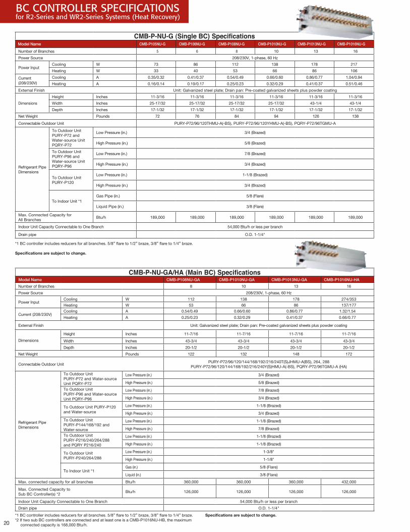
CMB-P-NU-GA/HA (Main BC) SpecificationsModel Name CMB-P108NU-GA CMB-P1010NU-GA CMB-P1013NU-GA CMB-P1016NU-HA
Number of Branches 8 10 13 16
Power Source 208/230V, 1-phase, 60 Hz
Power InputCooling W 112 138 178 274/353
Heating W 53 66 86 137/177
Current (208/230V) Cooling A 0.54/0.49 0.66/0.60 0.86/0.77 1.32/1.54
Heating A 0.25/0.23 0.32/0.29 0.41/0.37 0.66/0.77
External Finish Unit: Galvanized steel plate; Drain pan: Pre-coated galvanized sheets plus powder coating
Dimensions
Height Inches 11-7/16 11-7/16 11-7/16 11-7/16
Width Inches 43-3/4 43-3/4 43-3/4 43-3/4
Depth Inches 20-1/2 20-1/2 20-1/2 20-1/2
Net Weight Pounds 122 132 148 172
Connectable Outdoor UnitPURY-P72/96/120/144/168/192/216/240T(S)JHMU-A(BS), 264, 288
PURY-P72/96/120/144/168/192/216/240Y(S)HMU-A(-BS), PQRY-P72/96TGMU-A (HA)
Refrigerant Pipe Dimensions
To Outdoor Unit PURY-P72 and Water-source Unit PQRY-P72
Low Pressure (in.) 3/4 (Brazed)
High Pressure (in.) 5/8 (Brazed)
To Outdoor Unit PURY-P96 and Water-source Unit PQRY-P96
Low Pressure (in.) 7/8 (Brazed)
High Pressure (in.) 3/4 (Brazed)
To Outdoor Unit PURY-P120 and Water-source
Low Pressure (in.) 1-1/8 (Brazed)
High Pressure (in.) 3/4 (Brazed)
To Outdoor Unit PURY-P144/168/192 and Water-source
Low Pressure (in.) 1-1/8 (Brazed)
High Pressure (in.) 7/8 (Brazed)
To Outdoor Unit PURY-P216/240/264/288and PQRY P216/240
Low Pressure (in.) 1-1/8 (Brazed)
High Pressure (in.) 1-1/8 (Brazed)
To Outdoor Unit PURY-P240/264/288
Low Pressure (in.) 1-3/8"
High Pressure (in.) 1-1/8"
To Indoor Unit *1Gas (in.) 5/8 (Flare)
Liquid (in.) 3/8 (Flare)
Max. connected capacity for all branches Btu/h 360,000 360,000 360,000 432,000
Max. Connected Capacity to Sub BC Controller(s) *2
Btu/h 126,000 126,000 126,000 126,000
Indoor Unit Capacity Connectable to One Branch 54,000 Btu/h or less per branch
Drain pipe O.D. 1-1/4"
CMB-P-NU-G (Single BC) SpecificationsModel Name CMB-P105NU-G CMB-P106NU-G CMB-P108NU-G CMB-P1010NU-G CMB-P1013NU-G CMB-P1016NU-G
Number of Branches 5 6 8 10 13 16
Power Source 208/230V, 1-phase, 60 Hz
Power InputCooling W 73 86 112 138 178 217
Heating W 33 40 53 66 86 106
Current (208/230V)
Cooling A 0.35/0.32 0.41/0.37 0.54/0.49 0.66/0.60 0.86/0.77 1.04/0.94
Heating A 0.16/0.14 0.19/0.17 0.25/0.23 0.32/0.29 0.41/0.37 0.51/0.46
External Finish Unit: Galvanized steel plate; Drain pan: Pre-coated galvanized sheets plus powder coating
Dimensions
Height Inches 11-3/16 11-3/16 11-3/16 11-3/16 11-3/16 11-3/16
Width Inches 25-17/32 25-17/32 25-17/32 25-17/32 43-1/4 43-1/4
Depth Inches 17-1/32 17-1/32 17-1/32 17-1/32 17-1/32 17-1/32
Net Weight Pounds 72 76 84 94 126 138
Connectable Outdoor Unit PURY-P72/96/120THMU-A(-BS), PURY-P72/96/120YHMU-A(-BS), PQRY-P72/96TGMU-A
Refrigerant Pipe Dimensions
To Outdoor Unit PURY-P72 and Water-source Unit PQRY-P72
Low Pressure (in.) 3/4 (Brazed)
High Pressure (in.) 5/8 (Brazed)
To Outdoor Unit PURY-P96 and Water-source Unit PQRY-P96
Low Pressure (in.) 7/8 (Brazed)
High Pressure (in.) 3/4 (Brazed)
To Outdoor Unit PURY-P120
Low Pressure (in.) 1-1/8 (Brazed)
High Pressure (in.) 3/4 (Brazed)
To Indoor Unit *1Gas Pipe (in.) 5/8 (Flare)
Liquid Pipe (in.) 3/8 (Flare)
Max. Connected Capacity for All Branches
Btu/h 189,000 189,000 189,000 189,000 189,000 189,000
Indoor Unit Capacity Connectable to One Branch 54,000 Btu/h or less per branch
Drain pipe O.D. 1-1/4"
BC CONTROLLER SPECIFICATIONS for R2-Series and WR2-Series Systems (Heat Recovery)
*1 BC controller includes reducers for all branches. 5/8" flare to 1/2" braze, 3/8" flare to 1/4" braze.
Specificationsaresubjecttochange.
*1 BC controller includes reducers for all branches. 5/8" flare to 1/2" braze, 3/8" flare to 1/4" braze.*2 If two sub BC controllers are connected and at least one is a CMB-P1016NU-HB, the maximum
connected capacity is 168,000 Btu/h.
Specificationsaresubjecttochange.
21
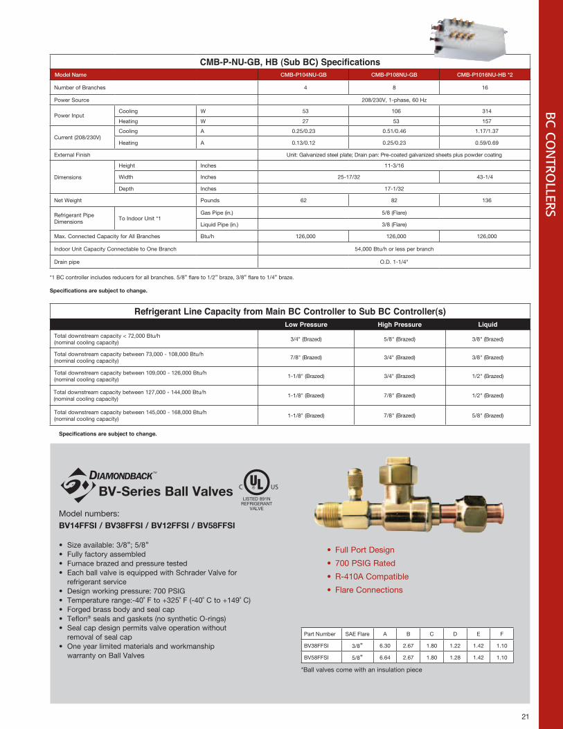
CMB-P-NU-GB, HB (Sub BC) SpecificationsModel Name CMB-P104NU-GB CMB-P108NU-GB CMB-P1016NU-HB *2
Number of Branches 4 8 16
Power Source 208/230V, 1-phase, 60 Hz
Power InputCooling W 53 106 314
Heating W 27 53 157
Current (208/230V)Cooling A 0.25/0.23 0.51/0.46 1.17/1.37
Heating A 0.13/0.12 0.25/0.23 0.59/0.69
External Finish Unit: Galvanized steel plate; Drain pan: Pre-coated galvanized sheets plus powder coating
Dimensions
Height Inches 11-3/16
Width Inches 25-17/32 43-1/4
Depth Inches 17-1/32
Net Weight Pounds 62 82 136
Refrigerant Pipe Dimensions
To Indoor Unit *1Gas Pipe (in.) 5/8 (Flare)
Liquid Pipe (in.) 3/8 (Flare)
Max. Connected Capacity for All Branches Btu/h 126,000 126,000 126,000
Indoor Unit Capacity Connectable to One Branch 54,000 Btu/h or less per branch
Drain pipe O.D. 1-1/4"
Specifications are subject to change.
BC
CO
NTRO
LLERS
Refrigerant Line Capacity from Main BC Controller to Sub BC Controller(s)Low Pressure High Pressure Liquid
Total downstream capacity < 72,000 Btu/h (nominal cooling capacity)
3/4" (Brazed) 5/8" (Brazed) 3/8" (Brazed)
Total downstream capacity between 73,000 - 108,000 Btu/h (nominal cooling capacity)
7/8" (Brazed) 3/4" (Brazed) 3/8" (Brazed)
Total downstream capacity between 109,000 - 126,000 Btu/h (nominal cooling capacity)
1-1/8" (Brazed) 3/4" (Brazed) 1/2" (Brazed)
Total downstream capacity between 127,000 - 144,000 Btu/h (nominal cooling capacity)
1-1/8" (Brazed) 7/8" (Brazed) 1/2" (Brazed)
Total downstream capacity between 145,000 - 168,000 Btu/h (nominal cooling capacity)
1-1/8" (Brazed) 7/8" (Brazed) 5/8" (Brazed)
*1 BC controller includes reducers for all branches. 5/8" flare to 1/2" braze, 3/8" flare to 1/4" braze.
Specificationsaresubjecttochange.
Model numbers:BV14FFSI/BV38FFSI/BV12FFSI/BV58FFSI
• Size available: 3/8"; 5/8"• Fully factory assembled• Furnace brazed and pressure tested• Each ball valve is equipped with Schrader Valve for
refrigerant service• Design working pressure: 700 PSIG• Temperature range:-40˚ F to +325˚ F (-40˚ C to +149˚ C)• Forged brass body and seal cap• Teflon® seals and gaskets (no synthetic O-rings)• Seal cap design permits valve operation without
removal of seal cap• One year limited materials and workmanship
warranty on Ball Valves
• Full Port Design
• 700 PSIG Rated
• R-410A Compatible
• Flare Connections
Part Number SAE Flare A B C D E F
BV38FFSI 3/8" 6.30 2.67 1.80 1.22 1.42 1.10
BV58FFSI 5/8" 6.64 2.67 1.80 1.28 1.42 1.10
*Ball valves come with an insulation piece
BV-SeriesBallValvesLISTED 891N
REFRIGERANTVALVE
C US
22
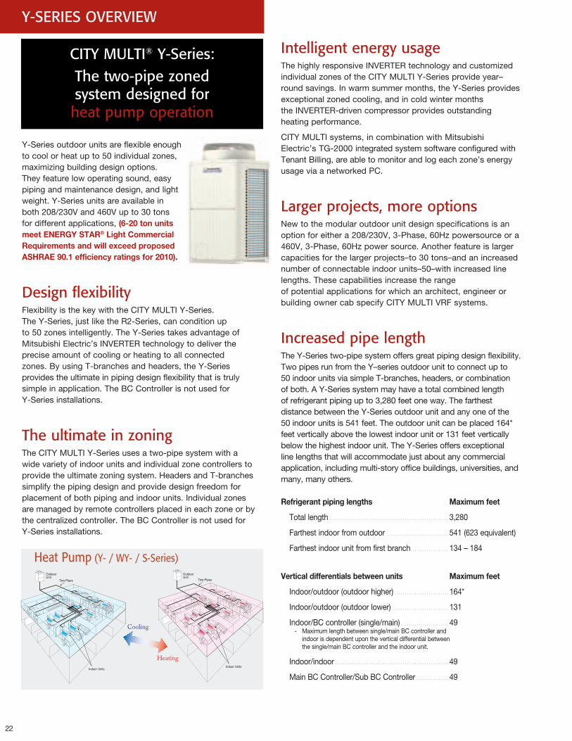
Y-SERIES OVERVIEW
Y-Series outdoor units are flexible enough to cool or heat up to 50 individual zones, maximizing building design options. They feature low operating sound, easy piping and maintenance design, and light weight. Y-Series units are available in both 208/230V and 460V up to 30 tons for different applications, (6-20tonunitsmeetENERGYSTAR®LightCommercialRequirementsandwillexceedproposedASHRAE90.1efficiencyratingsfor2010).
Design flexibilityFlexibility is the key with the CITY MULTI Y-Series. The Y-Series, just like the R2-Series, can condition up to 50 zones intelligently. The Y-Series takes advantage of Mitsubishi Electric’s INVERTER technology to deliver the precise amount of cooling or heating to all connected zones. By using T-branches and headers, the Y-Series provides the ultimate in piping design flexibility that is truly simple in application. The BC Controller is not used for Y-Series installations.
The ultimate in zoning The CITY MULTI Y-Series uses a two-pipe system with a wide variety of indoor units and individual zone controllers to provide the ultimate zoning system. Headers and T-branches simplify the piping design and provide design freedom for placement of both piping and indoor units. Individual zones are managed by remote controllers placed in each zone or by the centralized controller. The BC Controller is not used for Y-Series installations.
CITY MULTI® Y-Series: The two-pipe zoned system designed for heat pump operation
Intelligent energy usageThe highly responsive INVERTER technology and customized individual zones of the CITY MULTI Y-Series provide year–round savings. In warm summer months, the Y-Series provides exceptional zoned cooling, and in cold winter months the INVERTER-driven compressor provides outstanding heating performance.
CITY MULTI systems, in combination with Mitsubishi Electric’s TG-2000 integrated system software configured with Tenant Billing, are able to monitor and log each zone’s energy usage via a networked PC.
Larger projects, more optionsNew to the modular outdoor unit design specifications is an option for either a 208/230V, 3-Phase, 60Hz powersource or a 460V, 3-Phase, 60Hz power source. Another feature is larger capacities for the larger projects–to 30 tons–and an increased number of connectable indoor units–50–with increased line lengths. These capabilities increase the range of potential applications for which an architect, engineer or building owner cab specify CITY MULTI VRF systems.
Increased pipe lengthThe Y-Series two-pipe system offers great piping design flexibility. Two pipes run from the Y–series outdoor unit to connect up to 50 indoor units via simple T-branches, headers, or combination of both. A Y-Series system may have a total combined length of refrigerant piping up to 3,280 feet one way. The farthest distance between the Y-Series outdoor unit and any one of the 50 indoor units is 541 feet. The outdoor unit can be placed 164* feet vertically above the lowest indoor unit or 131 feet vertically below the highest indoor unit. The Y-Series offers exceptional line lengths that will accommodate just about any commercial application, including multi-story office buildings, universities, and many, many others.
Refrigerantpipinglengths Maximumfeet
Total length ............................................................3,280
Farthest indoor from outdoor ..............................541 (623 equivalent)
Farthest indoor unit from first branch ...................134 – 184
Verticaldifferentialsbetweenunits Maximumfeet
Indoor/outdoor (outdoor higher) ...........................164*
Indoor/outdoor (outdoor lower).............................131
Indoor/BC controller (single/main) ........................49 - Maximum length between single/main BC controller and
indoor is dependent upon the vertical differential between the single/main BC controller and the indoor unit.
Indoor/indoor .........................................................49
Main BC Controller/Sub BC Controller ................49
Heat Pump (Y- / WY- / S-Series)
23 23
OU
TDO
OR U
NITS
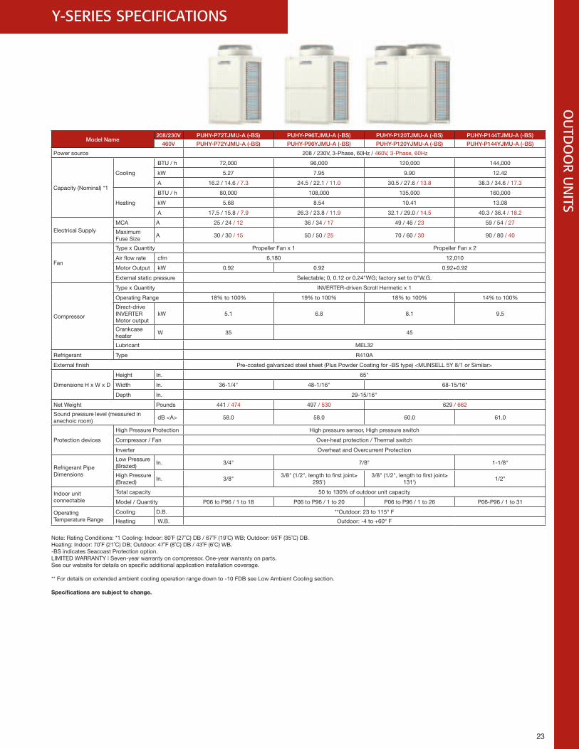
Y-SERIES SPECIFICATIONS
Model Name208/230V PUHY-P72TJMU-A (-BS) PUHY-P96TJMU-A (-BS) PUHY-P120TJMU-A (-BS) PUHY-P144TJMU-A (-BS)
460V PUHY-P72YJMU-A (-BS) PUHY-P96YJMU-A (-BS) PUHY-P120YJMU-A (-BS) PUHY-P144YJMU-A (-BS)
Power source 208 / 230V, 3-Phase, 60Hz / 460V, 3-Phase, 60Hz
Capacity (Nominal) *1
Cooling
BTU / h 72,000 96,000 120,000 144,000
kW 5.27 7.95 9.90 12.42
A 16.2 / 14.6 / 7.3 24.5 / 22.1 / 11.0 30.5 / 27.6 / 13.8 38.3 / 34.6 / 17.3
Heating
BTU / h 80,000 108,000 135,000 160,000
kW 5.68 8.54 10.41 13.08
A 17.5 / 15.8 / 7.9 26.3 / 23.8 / 11.9 32.1 / 29.0 / 14.5 40.3 / 36.4 / 18.2
Electrical SupplyMCA A 25 / 24 / 12 36 / 34 / 17 49 / 46 / 23 59 / 54 / 27
Maximum Fuse Size
A 30 / 30 / 15 50 / 50 / 25 70 / 60 / 30 90 / 80 / 40
Fan
Type x Quantity Propeller Fan x 1 Propeller Fan x 2
Air flow rate cfm 6,180 12,010
Motor Output kW 0.92 0.92 0.92+0.92
External static pressure Selectable; 0, 0.12 or 0.24"WG; factory set to 0"W.G.
Compressor
Type x Quantity INVERTER-driven Scroll Hermetic x 1
Operating Range 18% to 100% 19% to 100% 18% to 100% 14% to 100%
Direct-drive INVERTER Motor output
kW 5.1 6.8 8.1 9.5
Crankcase heater
W 35 45
Lubricant MEL32
Refrigerant Type R410A
External finish Pre-coated galvanized steel sheet (Plus Powder Coating for -BS type) <MUNSELL 5Y 8/1 or Similar>
Dimensions H x W x D
Height In. 65"
Width In. 36-1/4" 48-1/16" 68-15/16"
Depth In. 29-15/16"
Net Weight Pounds 441 / 474 497 / 530 629 / 662
Sound pressure level (measured in anechoic room)
dB <A> 58.0 58.0 60.0 61.0
Protection devices
High Pressure Protection High pressure sensor, High pressure switch
Compressor / Fan Over-heat protection / Thermal switch
Inverter Overheat and Overcurrent Protection
Refrigerant Pipe Dimensions
Low Pressure (Brazed)
In. 3/4" 7/8" 1-1/8"
High Pressure (Brazed)
In. 3/8"3/8" (1/2", length to first joint≥
295')3/8" (1/2", length to first joint≥
131')1/2"
Indoor unitconnectable
Total capacity 50 to 130% of outdoor unit capacity
Model / Quantity P06 to P96 / 1 to 18 P06 to P96 / 1 to 20 P06 to P96 / 1 to 26 P06-P96 / 1 to 31
Operating Temperature Range
Cooling D.B. **Outdoor: 23 to 115° F
Heating W.B. Outdoor: -4 to +60° F
Note: Rating Conditions: *1 Cooling: Indoor: 80˚F (27˚C) DB / 67˚F (19˚C) WB; Outdoor: 95˚F (35˚C) DB. Heating: Indoor: 70˚F (21˚C) DB; Outdoor: 47˚F (8˚C) DB / 43˚F (6˚C) WB. -BS indicates Seacoast Protection option. LIMITED WARRANTY | Seven-year warranty on compressor. One-year warranty on parts. See our website for details on specific additional application installation coverage.
** For details on extended ambient cooling operation range down to -10 FDB see Low Ambient Cooling section.
Specificationsaresubjecttochange.
24
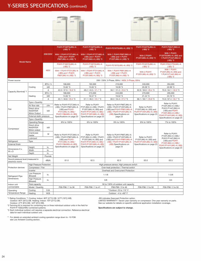
Model Name
208/230V
PUHY-P168TSJMU-A (-BS) *2
PUHY-P192TSJMU-A (-BS) *2
PUHY-P216TSJMU-A (-BS) *2PUHY-P240TSJMU-A
(-BS) *2PUHY-P264TJMU-A
(-BS) *2
With 1 PUHY-P72TJMU-A (-BS) and 1 PUHY-
P96TJMU-A (-BS) *3
With 1 PUHY-P72TJMU-A (-BS) and 1 PUHY-
P120TJMU-A (-BS) *3
With 1 PUHY-P96TJMU-A (-BS) and 1 PUHY-
P120TJMU-A (-BS) *3
With 2 PUHY-P120TJMU-A (-BS) *3
With 1 PUHY-P120TSUMU-A (-BS) and
1 PUHY-P144TJMU-A (-BS) *3
460V
PUHY-P168YSJMU-A (-BS) *2
PUHY-P192YSJMU-A (-BS) *2
PUHY-P216YSJMU-A (-BS) *2PUHY-P240YSJMU-A
(-BS) *2PUHY-P264YTSUMU-A
(-BS) *2
With 1 PUHY-P72YJMU-A (-BS) and 1 PUHY-
P96YJMU-A (-BS) *3
With 1 PUHY-P72YJMU-A (-BS) and 1 PUHY-
P120YJMU-A (-BS) *3
With 1 PUHY-P96YJMU-A (-BS) and 1 PUHY-
P120YJMU-A (-BS) *3
With 2 PUHY-P120YJMU-A (-BS) *3
With 1 PUHY-P120YJMU-A (-BS) and 1 PUHY-P144YJMU-A
(-BS) *3
Power source 208 / 230V, 3-Phase, 60Hz / 460V, 3-Phase, 60Hz
Capacity (Nominal) *1
Cooling
BTU / h 168,000 192,000 216,000 240,000 264,000
kW 13.62 *3 15.63 *3 18.39 *3 20.39 *3 22.99 *3
A 42.0 / 37.9 / 18.9 *3 48.2 / 43.5 / 21.7 *3 56.7 / 51.2 / 25.6 *3 62.8 / 56.8 / 28.4 *3 70.9 / 64.1 / 32.0 *3
Heating
BTU / h 188,000 215,000 243,000 270,000 295,000
kW 14.65 *3 16.57 *3 19.52 *3 21.44 *3 24.19 *3
A 45.1 / 40.8 / 20.4 *3 51.1 / 46.2 / 23.1 *3 60.2 / 54.4 / 27.2 *3 66.1 / 59.7 / 29.8 *3 74.6 / 67.4 / 33.7 *3
Fan
Type x QuantityRefer to PUHY-P72TJMU-A (-BS) / PUHY-P96TJMU-A
(-BS) and PUHY-P72YJMU-A (-BS) /
PUHY-Y96JMU-A (-BS) Specifications on page 23
Refer to PUHY-P72TJMU-A (-BS) / PUHY-
P120TJMU-A (-BS) and PUHY-P72YJMU-A (-BS) / PUHY-P120YJMU-A (-BS) Specifications on page 23
Refer to PUHY-P96TJMU-A (-BS) / PUHY-P120TJMU-A
(-BS) and PUHY-P96YJMU-A (-BS) / PUHY-P120YJMU-A
(-BS) Specifications on page 23
Refer to PUHY-P120TJMU-A (-BS) and
PUHY-P120YJMU-A (-BS) Specifications on page 23
Refer to PUHY-P120TJMU-A (-BS) / PUHY-P144TJMU-A
(-BS) and PUHY-P120YJMU-A (-BS) /
PUHY-P144YJMU-A (-BS) Specifications on page 23
Air flow rate cfm
Direct-drive INVERTER Motor Output
kW
External static pressure
Compressor
Type x Quantity
Operating Range 8% to 100% 6% to 100% 9% to 100% 8% to 100% 7% to 100%
Direct-drive INVERTER Motor output
kW
Refer to PUHY-P72TJMU-A (-BS) / PUHY-P96TJMU-A
(-BS) and PUHY-P72YJMU-A (-BS) /
PUHY-Y96JMU-A (-BS) Specifications on page 23
Refer to PUHY-P72TJMU-A (-BS) / PUHY-
P120TJMU-A (-BS) and PUHY-P72YJMU-A (-BS) / PUHY-P120YJMU-A (-BS) Specifications on page 23
Refer to PUHY-P96TJMU-A (-BS) / PUHY-P120TJMU-A
(-BS) and PUHY-P96YJMU-A (-BS) / PUHY-P120YJMU-A
(-BS) Specifications on page 23
Refer to PUHY-P120TJMU-A (-BS) and
PUHY-P120YJMU-A (-BS) Specifications on page 23
Refer to PUHY-P120TJMU-A (-BS) / PUHY-P144TJMU-A
(-BS) and PUHY-P120YJMU-A (-BS) /
PUHY-P144YJMU-A (-BS) Specifications on page 23
Crankcase heater
W
Lubricant
Refrigerant Type
External finish
Dimensions H x W x D
Height In.
Width In.
Depth In.
Net Weight Pounds
Sound pressure level (measured in anechoic room)
dB(A) 61.0 62.5 62.5 63.0 63.5
Protection devices
High Pressure Protection High pressure sensor, High pressure switch
Compressor / Fan Over-heat protection / Thermal switch
Inverter Overheat and Overcurrent Protection
Refrigerant Pipe Dimensions
Low Pressure (Brazed)
In. 1-1/8 1-3/8
High Pressure (Brazed)
In. 5/8 3/4
Indoor unitconnectable
Total capacity 50 to 130% of outdoor unit capacity
Model / Quantity P06-P96 / 1 to 36 P06-P96 / 1 to 41 P06-P96 / 2 to 46 P06-P96 / 2 to 50 P06-P96 / 2 to 50
Operating Temperature Range
Cooling D.B. **Outdoor: 23 to 115° F
Heating W.B. Outdoor: -4 to +60° F
Y-SERIES SPECIFICATIONS (continued)
*1 Rating Conditions: *1 Cooling: Indoor: 80˚F (27˚C) DB / 67˚F (19˚C) WB; Outdoor: 95˚F (35˚C) DB. Heating: Indoor: 70˚F (21˚C) DB; Outdoor: 47˚F (8˚C) DB / 43˚F (6˚C) WB.*2 Twinning Kit is required for combining two or three individual outdoor units in the field for PUHY-P-T(S)SJHMU combined systems.*3 Each individual outdoor unit requires a separate electrical connection. Reference electrical data for each individual outdoor unit.
** For details on extended ambient cooling operation range down to -10 FDB see Low Ambient Cooling section.
-BS indicates Seacoast Protection option.LIMITED WARRANTY | Seven-year warranty on compressor. One-year warranty on parts. See our website for details on specific additional application installation coverage..
Specificationsaresubjecttochange.
25
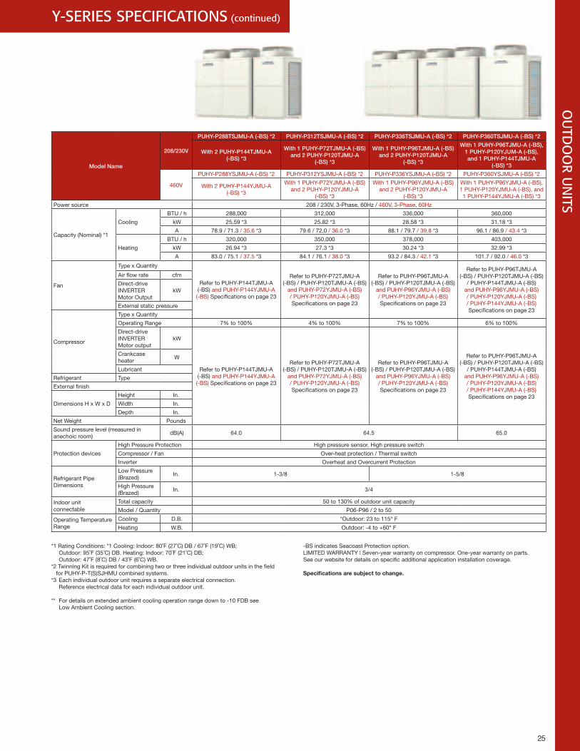
Y-SERIES SPECIFICATIONS (continued)
25
OU
TDO
OR U
NITS
*1 Rating Conditions: *1 Cooling: Indoor: 80˚F (27˚C) DB / 67˚F (19˚C) WB; Outdoor: 95˚F (35˚C) DB. Heating: Indoor: 70˚F (21˚C) DB; Outdoor: 47˚F (8˚C) DB / 43˚F (6˚C) WB.
*2 Twinning Kit is required for combining two or three individual outdoor units in the field for PUHY-P-T(S)SJHMU combined systems.*3 Each individual outdoor unit requires a separate electrical connection. Reference electrical data for each individual outdoor unit.
** For details on extended ambient cooling operation range down to -10 FDB see Low Ambient Cooling section.
-BS indicates Seacoast Protection option.LIMITED WARRANTY | Seven-year warranty on compressor. One-year warranty on parts. See our website for details on specific additional application installation coverage.
Specificationsaresubjecttochange.
Model Name
208/230V
PUHY-P288TSJMU-A (-BS) *2 PUHY-P312TSJMU-A (-BS) *2 PUHY-P336TSJMU-A (-BS) *2 PUHY-P360TSJMU-A (-BS) *2
With 2 PUHY-P144TJMU-A (-BS) *3
With 1 PUHY-P72TJMU-A (-BS) and 2 PUHY-P120TJMU-A
(-BS) *3
With 1 PUHY-P96TJMU-A (-BS) and 2 PUHY-P120TJMU-A
(-BS) *3
With 1 PUHY-P96TJMU-A (-BS), 1 PUHY-P120YJUM-A (-BS), and 1 PUHY-P144TJMU-A
(-BS) *3
460V
PUHY-P288YSJMU-A (-BS) *2 PUHY-P312YSJMU-A (-BS) *2 PUHY-P336YSJMU-A (-BS) *2 PUHY-P360YSJMU-A (-BS) *2
With 2 PUHY-P144YJMU-A (-BS) *3
With 1 PUHY-P72YJMU-A (-BS) and 2 PUHY-P120YJMU-A
(-BS) *3
With 1 PUHY-P96YJMU-A (-BS) and 2 PUHY-P120YJMU-A
(-BS) *3
With 1 PUHY-P96YJMU-A (-BS), 1 PUHY-P120YJMU-A (-BS), and 1 PUHY-P144YJMU-A (-BS) *3
Power source 208 / 230V, 3-Phase, 60Hz / 460V, 3-Phase, 60Hz
Capacity (Nominal) *1
Cooling
BTU / h 288,000 312,000 336,000 360,000
kW 25.59 *3 25.82 *3 28.58 *3 31.18 *3
A 78.9 / 71.3 / 35.6 *3 79.6 / 72.0 / 36.0 *3 88.1 / 79.7 / 39.8 *3 96.1 / 86.9 / 43.4 *3
Heating
BTU / h 320,000 350,000 378,000 403,000
kW 26.94 *3 27.3 *3 30.24 *3 32.99 *3
A 83.0 / 75.1 / 37.5 *3 84.1 / 76.1 / 38.0 *3 93.2 / 84.3 / 42.1 *3 101.7 / 92.0 / 46.0 *3
Fan
Type x Quantity
Refer to PUHY-P144TJMU-A (-BS) and PUHY-P144YJMU-A (-BS) Specifications on page 23
Refer to PUHY-P72TJMU-A (-BS) / PUHY-P120TJMU-A (-BS)
and PUHY-P72YJMU-A (-BS) / PUHY-P120YJMU-A (-BS) Specifications on page 23
Refer to PUHY-P96TJMU-A (-BS) / PUHY-P120TJMU-A (-BS)
and PUHY-P96YJMU-A (-BS) / PUHY-P120YJMU-A (-BS) Specifications on page 23
Refer to PUHY-P96TJMU-A (-BS) / PUHY-P120TJMU-A (-BS)
/ PUHY-P144TJMU-A (-BS) and PUHY-P96YJMU-A (-BS) / PUHY-P120YJMU-A (-BS) / PUHY-P144YJMU-A (-BS) Specifications on page 23
Air flow rate cfm
Direct-drive INVERTER Motor Output
kW
External static pressure
Compressor
Type x Quantity
Operating Range 7% to 100% 4% to 100% 7% to 100% 6% to 100%
Direct-drive INVERTER Motor output
kW
Refer to PUHY-P144TJMU-A (-BS) and PUHY-P144YJMU-A (-BS) Specifications on page 23
Refer to PUHY-P72TJMU-A (-BS) / PUHY-P120TJMU-A (-BS)
and PUHY-P72YJMU-A (-BS) / PUHY-P120YJMU-A (-BS) Specifications on page 23
Refer to PUHY-P96TJMU-A (-BS) / PUHY-P120TJMU-A (-BS)
and PUHY-P96YJMU-A (-BS) / PUHY-P120YJMU-A (-BS) Specifications on page 23
Refer to PUHY-P96TJMU-A (-BS) / PUHY-P120TJMU-A (-BS)
/ PUHY-P144TJMU-A (-BS) and PUHY-P96YJMU-A (-BS) / PUHY-P120YJMU-A (-BS) / PUHY-P144YJMU-A (-BS) Specifications on page 23
Crankcase heater
W
Lubricant
Refrigerant Type
External finish
Dimensions H x W x D
Height In.
Width In.
Depth In.
Net Weight Pounds
Sound pressure level (measured in anechoic room)
dB(A) 64.0 64.5 65.0
Protection devices
High Pressure Protection High pressure sensor, High pressure switch
Compressor / Fan Over-heat protection / Thermal switch
Inverter Overheat and Overcurrent Protection
Refrigerant Pipe Dimensions
Low Pressure (Brazed)
In. 1-3/8 1-5/8
High Pressure (Brazed)
In. 3/4
Indoor unitconnectable
Total capacity 50 to 130% of outdoor unit capacity
Model / Quantity P06-P96 / 2 to 50
Operating Temperature Range
Cooling D.B. *Outdoor: 23 to 115° F
Heating W.B. Outdoor: -4 to +60° F
26
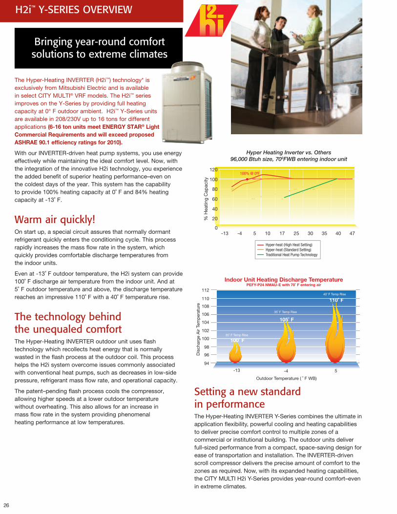
H2i™ Y-SERIES OVERVIEW
Hyper Heating Inverter vs. Others96,000 Btuh size, 700FWB entering indoor unit
Hyper-heat (High Heat Setting)Hyper-heat (Standard Setting)Traditional Heat Pump Technology
100% @ 00F
Setting a new standard in performanceThe Hyper-Heating INVERTER Y-Series combines the ultimate in application flexibility, powerful cooling and heating capabilities to deliver precise comfort control to multiple zones of a commercial or institutional building. The outdoor units deliver full-sized performance from a compact, space-saving design for ease of transportation and installation. The INVERTER-driven scroll compressor delivers the precise amount of comfort to the zones as required. Now, with its expanded heating capabilities, the CITY MULTI H2i Y-Series provides year-round comfort–even in extreme climates.
The Hyper-Heating INVERTER (H2i™) technology* is exclusively from Mitsubishi Electric and is available in select CITY MULTI® VRF models. The H2i™ series improves on the Y-Series by providing full heating capacity at 0° F outdoor ambient. H2i™ Y-Series units are available in 208/230V up to 16 tons for different applications (6-16tonunitsmeetENERGYSTAR®LightCommercialRequirementsandwillexceedproposedASHRAE90.1efficiencyratingsfor2010).
With our INVERTER-driven heat pump systems, you use energy effectively while maintaining the ideal comfort level. Now, with the integration of the innovative H2i technology, you experience the added benefit of superior heating performance–even on the coldest days of the year. This system has the capability to provide 100% heating capacity at 0˚ F and 84% heating capacity at -13˚ F.
Warm air quickly!On start up, a special circuit assures that normally dormant refrigerant quickly enters the conditioning cycle. This process rapidly increases the mass flow rate in the system, which quickly provides comfortable discharge temperatures from the indoor units.
Even at -13˚ F outdoor temperature, the H2i system can provide 100˚ F discharge air temperature from the indoor unit. And at 5˚ F outdoor temperature and above, the discharge temperature reaches an impressive 110˚ F with a 40˚ F temperature rise.
The technology behind the unequaled comfortThe Hyper-Heating INVERTER outdoor unit uses flash technology which recollects heat energy that is normally wasted in the flash process at the outdoor coil. This process helps the H2i system overcome issues commonly associated with conventional heat pumps, such as decreases in low-side pressure, refrigerant mass flow rate, and operational capacity.
The patent–pending flash process cools the compressor, allowing higher speeds at a lower outdoor temperature without overheating. This also allows for an increase in mass flow rate in the system providing phenomenal heating performance at low temperatures.
Bringing year-round comfort solutions to extreme climates
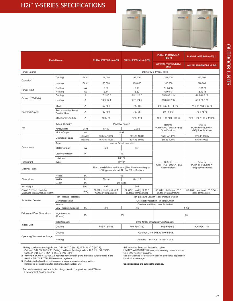
27
*1 Rating conditions (cooling)-Indoor: D .B . 26 .7º C (80º F), W .B . 19 .4º C (67º F); Outdoor: D .B . 35º C (95º F) . Rating conditions (heating)-Indoor: D .B . 21 .1º C (70º F); Outdoor: D .B . 8 .3º C (47º F), W .B . 6 .1º C (43º F) .
*2 Twinning Kit CMY-Y100VBK2 is required for combining two individual outdoor units in the fieldforPUHY-HP-TSHJMUcombinedsystems.*3 Each individual outdoor unit requires a separate electrical connection . Reference electrical data for each individual outdoor unit .
** For details on extended ambient cooling operation range down to 0 FDB see Low Ambient Cooling section.
-BS indicates Seacoast Protection option .LIMITED WARRANTY | Seven-year warranty on compressor. One-year warranty on parts. See our website for details on specific additional application installation coverage.
Specifications are subject to change.
OU
TDO
OR U
NITS
H2i™ Y-SERIES SPECIFICATIONS
Model Name PUHY-HP72TJMU-A (-BS) PUHY-HP96TJMU-A (-BS)
PUHY-HP144TSJMU-A (-BS) *2
PUHY-HP192TSJMU-A (-BS) *2
With 2 PUHY-HP72TJMU-A (-BS)
With 2 PUHY-HP96TJMU-A (BS)
Power Source 208/230V, 3-Phase, 60Hz
Capacity *1Cooling Btu/h 72,000 96,000 144,000 192,000
Heating Btu/h 80,000 108,000 160,000 216,000
Power InputCooling kW 5.60 8.16 11.54 *3 16.81 *3
Heating kW 6.14 8.80 12.65 *3 18.13 *3
Current (208/230V) Cooling A 17.2-15.6 25.1-22.7 35.5-32.1 *3 51.8-46.8 *3
Heating A 18.9-17.1 27.1-24.5 39.0-35.2 *3 55.9-50.5 *3
Electrical Supply
MCA A 59 / 54 74 / 68 59 + 59 / 54 + 54 *3 74 + 74 / 68 + 68 *3
Recommended Fuse/Breaker Size
A 60 / 60 75 / 75 60 + 60 *3 75 + 75 *3
Maximum Fuse Size A 100 / 90 120 / 110 100 + 100 / 90 + 90 *3 120 + 120 / 110 + 110 *3
Fan
Type x Quantity Propeller Fan x 1 Refer to PUHY-HP72TJMU-A (-BS)
Specifications
Refer to PUHY-HP96TJMU-A (-BS) Specifications
Airflow Rate CFM 6,180 7,950
Motor Output kW 0.92
Compressor
Operating RangeCooling 30% to 100% 23% to 100% 15% to 100% 12% to 100%
Heating 16% to 100% 13% to 100% 8% to 100% 6% to 100%
Type Inverter Scroll Hermetic
Refer to PUHY-HP72TJMU-A (-BS)
Specifications
Refer to PUHY-HP96TJMU-A (-BS) Specifications
Motor Output kW 5.3 6.7
Crankcase Heater W 45
Lubricant MEL32
Refrigerant Type R410A
External FinishPre-coated Galvanized Sheets (Plus Powder-coating for
-BS types) <Munsell No. 5Y 8/1 or Similar>
Dimensions
Height In. 65
Width In. 36-1/4 48-1/16
Depth In. 29-15/16
Net Weight Lbs. 497 585
Sound Pressure Level (As Measured in an Anechoic Room)
dB(A)56 (61 in Heating at -5º F
Outdoor Temperature)57 (62 in Heating at -5º F
Outdoor Temperature)59 (64 in Heating at -5º F
Outdoor Temperature)60 (65 in Heating at -5º F Out-
door Temperature)
Protection Devices
High Pressure Protection High-pressure Sensor, High-pressure Switch
Compressor/Fan Overheat Protection / Thermal Switch
Inverter Overheat and Overcurrent Protection
Refrigerant Pipe Dimensions
Low Pressure (Brazed) In. 3/4 7/8 1-1/8
High Pressure (Brazed)
In. 1/2 5/8
Indoor UnitTotal Capacity 50 to 130% of Outdoor Unit Capacity
Quantity P06-P72/1-15 P06-P96/1-20 P06-P96/1-31 P06-P96/1-41
Operating Temperature Range
Cooling **Outdoor: 23º F D.B. to 109º F D.B.
Heating Outdoor: -13º F W.B. to +60º F W.B.
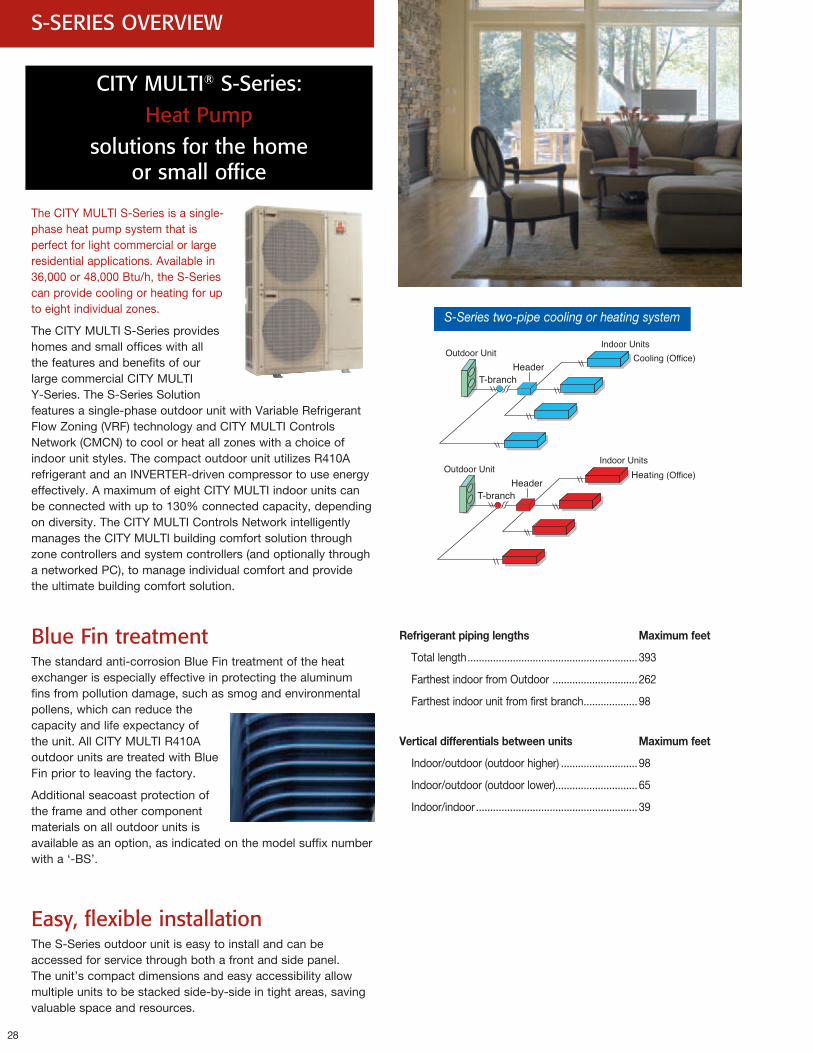
28
S-SERIES OVERVIEW
The CITY MULTI S-Series is a single- phase heat pump system that is perfect for light commercial or large residential applications. Available in 36,000 or 48,000 Btu/h, the S-Series can provide cooling or heating for up to eight individual zones.
The CITY MULTI S-Series provides homes and small offices with all the features and benefits of our large commercial CITY MULTI Y-Series. The S-Series Solution features a single-phase outdoor unit with Variable Refrigerant Flow Zoning (VRF) technology and CITY MULTI Controls Network (CMCN) to cool or heat all zones with a choice of indoor unit styles. The compact outdoor unit utilizes R410A refrigerant and an INVERTER-driven compressor to use energy effectively. A maximum of eight CITY MULTI indoor units can be connected with up to 130% connected capacity, depending on diversity. The CITY MULTI Controls Network intelligently manages the CITY MULTI building comfort solution through zone controllers and system controllers (and optionally through a networked PC), to manage individual comfort and provide the ultimate building comfort solution.
Blue Fin treatmentThe standard anti-corrosion Blue Fin treatment of the heat exchanger is especially effective in protecting the aluminum fins from pollution damage, such as smog and environmental pollens, which can reduce the capacity and life expectancy of the unit. All CITY MULTI R410A outdoor units are treated with Blue Fin prior to leaving the factory.
Additional seacoast protection of the frame and other component materials on all outdoor units is available as an option, as indicated on the model suffix number with a ‘-BS’.
Easy, flexible installation The S-Series outdoor unit is easy to install and can be accessed for service through both a front and side panel. The unit’s compact dimensions and easy accessibility allow multiple units to be stacked side-by-side in tight areas, saving valuable space and resources.
CITY MULTI® S-Series: Heat Pump
solutions for the home or small office
S-Series two-pipe cooling or heating system
Refrigerantpipinglengths Maximumfeet
Total length ............................................................393
Farthest indoor from Outdoor ..............................262
Farthest indoor unit from first branch ...................98
Verticaldifferentialsbetweenunits Maximumfeet
Indoor/outdoor (outdoor higher) ...........................98
Indoor/outdoor (outdoor lower).............................65
Indoor/indoor .........................................................39
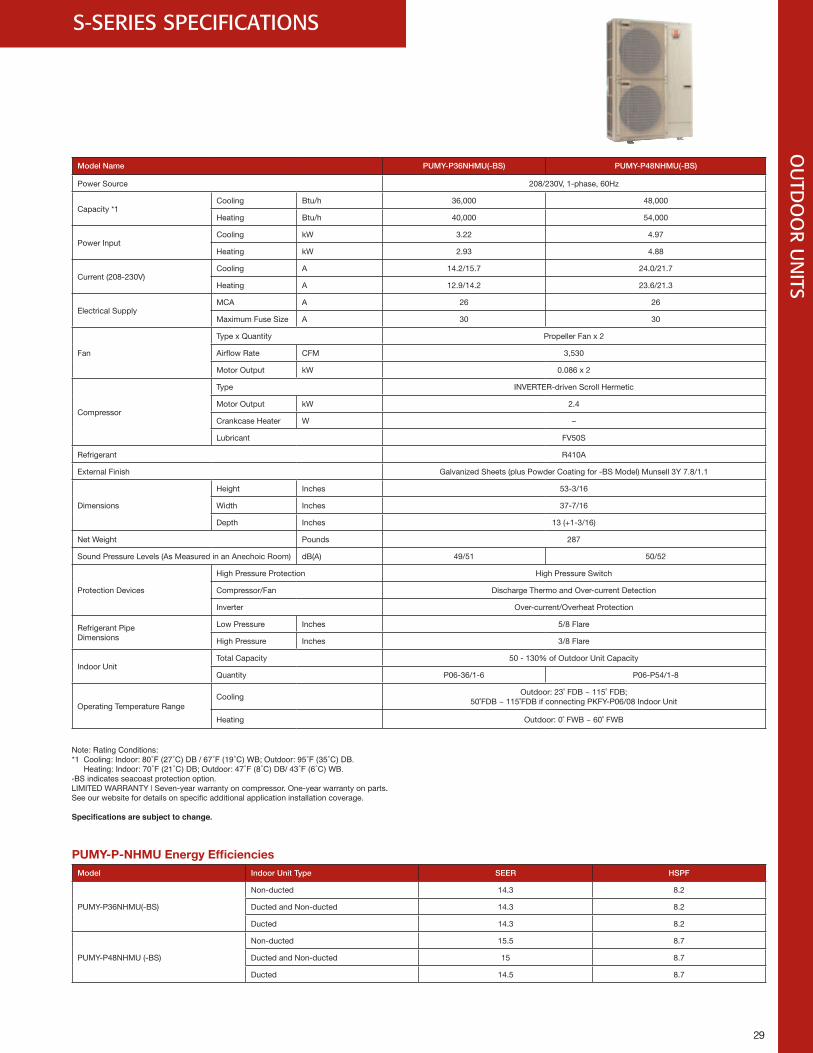
29
S-SERIES SPECIFICATIONS
Model Name PUMY-P36NHMU(-BS) PUMY-P48NHMU(-BS)
Power Source 208/230V, 1-phase, 60Hz
Capacity *1Cooling Btu/h 36,000 48,000
Heating Btu/h 40,000 54,000
Power InputCooling kW 3.22 4.97
Heating kW 2.93 4.88
Current (208-230V)Cooling A 14.2/15.7 24.0/21.7
Heating A 12.9/14.2 23.6/21.3
Electrical SupplyMCA A 26 26
Maximum Fuse Size A 30 30
Fan
Type x Quantity Propeller Fan x 2
Airflow Rate CFM 3,530
Motor Output kW 0.086 x 2
Compressor
Type INVERTER-driven Scroll Hermetic
Motor Output kW 2.4
Crankcase Heater W –
Lubricant FV50S
Refrigerant R410A
External Finish Galvanized Sheets (plus Powder Coating for -BS Model) Munsell 3Y 7.8/1.1
Dimensions
Height Inches 53-3/16
Width Inches 37-7/16
Depth Inches 13 (+1-3/16)
Net Weight Pounds 287
Sound Pressure Levels (As Measured in an Anechoic Room) dB(A) 49/51 50/52
Protection Devices
High Pressure Protection High Pressure Switch
Compressor/Fan Discharge Thermo and Over-current Detection
Inverter Over-current/Overheat Protection
Refrigerant Pipe Dimensions
Low Pressure Inches 5/8 Flare
High Pressure Inches 3/8 Flare
Indoor UnitTotal Capacity 50 - 130% of Outdoor Unit Capacity
Quantity P06-36/1-6 P06-P54/1-8
Operating Temperature RangeCooling
Outdoor: 23˚ FDB ~ 115˚ FDB; 50˚FDB ~ 115˚FDB if connecting PKFY-P06/08 Indoor Unit
Heating Outdoor: 0˚ FWB ~ 60˚ FWB
Note: Rating Conditions: *1 Cooling:Indoor:80˚F(27˚C)DB/67˚F(19˚C)WB;Outdoor:95˚F(35˚C)DB. Heating:Indoor:70˚F(21˚C)DB;Outdoor:47˚F(8˚C)DB/43˚F(6˚C)WB. -BS indicates seacoast protection option .LIMITED WARRANTY | Seven-year warranty on compressor. One-year warranty on parts. See our website for details on specific additional application installation coverage.
Specifications are subject to change.
29
OU
TDO
OR U
NITS
PUMY-P-NHMUEnergyEfficienciesModel Indoor Unit Type SEER HSPF
PUMY-P36NHMU(-BS)
Non-ducted 14.3 8.2
Ducted and Non-ducted 14.3 8.2
Ducted 14.3 8.2
PUMY-P48NHMU (-BS)
Non-ducted 15.5 8.7
Ducted and Non-ducted 15 8.7
Ducted 14.5 8.7
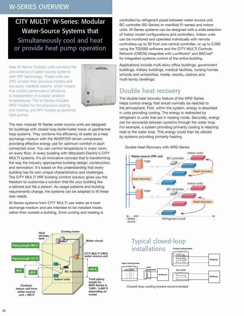
30
New W-Series modular units combine the convenience of water-source systems with VRF technology. These units are 30% smaller than previous models and are easily installed indoors, which means that system performance efficiency is independent of outdoor ambient temperatures. The W-Series includes WR2 models for simultaneous cooling and heating, and WY models as powerful heat pumps.
The new modular W-Series water-source units are designed for buildings with closed loop boiler/water tower or geothermal loop systems. They combine the efficiency of water as a heat exchange medium with the INVERTER-driven compressor, providing effective energy use for optimum comfort in each connected zone. You can control temperature in every room, on every floor, in every building with Mitsubishi Electric’s CITY MULTI systems. It’s an innovative concept that is transforming the way the industry approaches building design, construction, and renovation. It’s based on the understanding that every building has its own unique characteristics and challenges. The CITY MULTI VRF building comfort solution gives you the freedom to customize a solution that fits your building like a tailored suit fits a person. As usage patterns and building requirements change, the systems can be adapted to fit these new needs.
W-Series systems from CITY MULTI use water as a heat exchange medium and are intended to be installed inside, rather than outside a building. Zone cooling and heating is
W-SERIES OVERVIEW
PQRY
PQRY
Water-source VRF unit
Double Heat Recovery with WR2-Series
49 ft 164 ft
Piping length 360 ft
Heatstoragetank
Indoor units
Cooling tower
waterCITY MULTI VRFZ
-source unit
BC controller49 ft
Water circuit
Total piping length for WR2-Series is 1,804 - 2,460 ftdepending on model
Furthest indoor unit fromwater-source unit = 492 ft
Piping length 131 ft
Typical closed-loop installations Closed cooling tower
Dry cooler
Open cooling tower
W-Series
W-Series
W-Series
Heatexchanger
Closed cooling tower
Dry cooler
Open cooling tower
W-Series
W-Series
W-Series
Heatexchanger
Closed-loop cooling towers recommended
CITY MULTI® W-Series: ModularWater-Source Systems that
Simultaneously cool and heat or provide heat pump operation
controlled by refrigerant piped between water-source unit, BC controller (R2-Series) or manifold (Y-series) and indoor units. W-Series systems can be designed with a wide selection of indoor model configurations and controllers. Indoor units can be monitored and operated individually with remote controllers–up to 50 from one central controller, or up to 2,000 using the TG2000 software and the CITY MULTI Controls Network (CMCN) integrates with LonWorks® and BACnet® for integrated systems control of the entire building.
Applications include multi-story office buildings, government buildings, military buildings, medical facilities, nursing homes, schools and universities, hotels, resorts, casinos and multi-family dwellings.
Double heat recoveryThe double-heat recovery feature of the WR2-Series helps control energy that would normally be rejected to the atmosphere. First, within the system, energy is absorbed in units providing cooling. The energy is redirected by refrigerant to units that are in heating mode. Secondly, energy can be recovered between systems through the water loop. For example, a system providing primarily cooling is rejecting heat to the water loop. This energy could then be utilized by systems providing primarily heating.
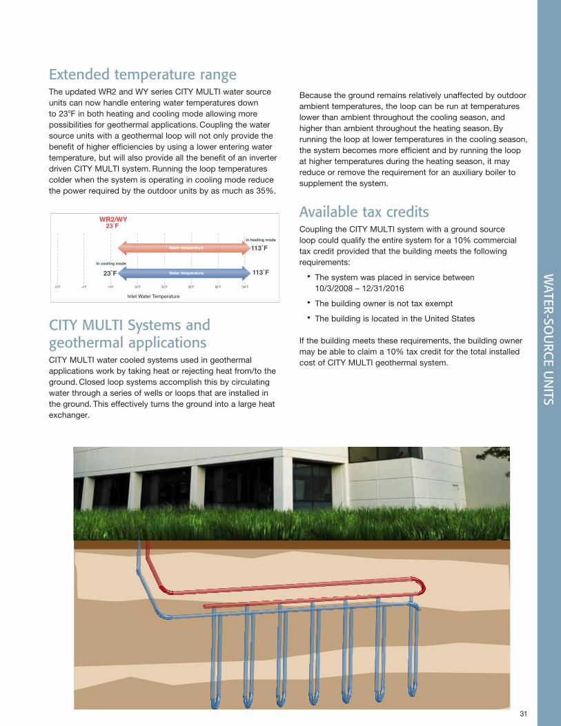
31
WATER-SO
URC
E UN
ITS
Extended temperature rangeThe updated WR2 and WY series CITY MULTI water source units can now handle entering water temperatures down to 23oF in both heating and cooling mode allowing more possibilities for geothermal applications. Coupling the water source units with a geothermal loop will not only provide the benefit of higher efficiencies by using a lower entering water temperature, but will also provide all the benefit of an inverter driven CITY MULTI system. Running the loop temperatures colder when the system is operating in cooling mode reduce the power required by the outdoor units by as much as 35%.
CITY MULTI Systems and geothermal applicationsCITY MULTI water cooled systems used in geothermal applications work by taking heat or rejecting heat from/to the ground. Closed loop systems accomplish this by circulating water through a series of wells or loops that are installed in the ground. This effectively turns the ground into a large heat exchanger.
Because the ground remains relatively unaffected by outdoor ambient temperatures, the loop can be run at temperatures lower than ambient throughout the cooling season, and higher than ambient throughout the heating season. By running the loop at lower temperatures in the cooling season, the system becomes more efficient and by running the loop at higher temperatures during the heating season, it may reduce or remove the requirement for an auxiliary boiler to supplement the system.
Available tax creditsCoupling the CITY MULTI system with a ground source loop could qualify the entire system for a 10% commercial tax credit provided that the building meets the following requirements:
•The system was placed in service between 10/3/2008 – 12/31/2016
•The building owner is not tax exempt
•The building is located in the United States
If the building meets these requirements, the building owner may be able to claim a 10% tax credit for the total installed cost of CITY MULTI geothermal system.
-4˚F-13˚F 14˚F 32˚F 50˚F 68˚F 86˚F 104˚F
In cooling mode
Water temperature
Water temperature
23˚FWR2/WY
113˚FIn heating mode
23˚F 113˚F
Inlet Water Temperature
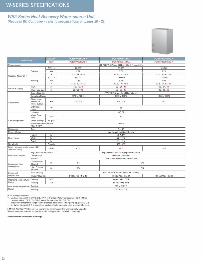
32
W-SERIES SPECIFICATIONS
WR2-Series Heat Recovery Water-source Unit (Requires BC Controller - refer to specifications on pages 20 - 21)
Model Name208/230V PQRY-P72THMU-A PQRY-P96THMU-A PQRY-P120THMU-A
460V PQRY-P72YHMU-A PQRY-P96YHMU-A PQRY-P120YHMU-A
Power source 208 / 230V, 3-Phase, 60Hz / 460V, 3-Phase, 60Hz
Capacity (Nominal) *1
Cooling
BTU / h 72,700 96,300 120,000
kW 3.97 5.77 7.73
A 12.6 / 11.4 / 5.7 17.9 / 16.2 / 8.1 23.6 / 21.4 / 10.6
Heating
BTU / h 80,000 108,000 135,000
kW 3.83 6.18 7.62
A 11.8 / 10.7 / 5.3 19.1 / 17.2 / 8.6 23.5 / 21.3 / 10.6
Electrical SupplyMCA A 16 / 15 / 8 23 / 21 / 11 30 / 27 / 14
Max. Fuse Size A 20 / 20 / 15 30 / 30 / 15 40 / 40 / 20
Compressor
Type x Quantity INVERTER-driven Scroll Hermetic x 1
Operating Range 23% to 100% 19% to 100% 14% to 100%
Direct-drive INVERTER Motor output
kW 4.5 / 4.6 6.2 / 6.3 8.5
Crankcase heater
W 51
Lubricant MEL32
Circulating Water
Water Flow Rate
GPM 25
Pressure Drop Ft. (psi)6 / (3)Max Water Pressure 290
PSI / 2 MPA
Refrigerant Type R410A
External finish Acrylic-painted Steel Sheets
Dimensions
Height In. 43-5/16"
Width In. 34-11/16"
Depth In. 21-11/16"
Net Weight Pounds 402 / 428
Sound pressure level (measured in anechoic room)
dB(A) 47.0 49.0 51.0
Protection devices
High Pressure Protection High pressure sensor, High pressure switch
Compressor Overheat protection
Inverter Overheat and Overcurrent Protection
Refrigerant Pipe Dimensions
Low Pressure (Brazed)
In. 3/4 7/8
High Pressure (Brazed)
In. 5/8 3/4
Indoor unitconnectable
Total capacity 50 to 150% of water-source unit capacity
Model / Quantity P06 to P96 / 1 to 18 P06 to P96 / 1 to 24 P06 to P96 / 1 to 30
Operating Temperature Range
Cooling W.B. Indoor: 59 to 75° F
Heating D.B. Indoor: 59 to 81° F
Inlet Water Temperature Range
Cooling *50 to 113° F
Heating *50 to 113° F
Note: Rating Conditions*1 Cooling: Indoor: 80° F (27°C) DB / 67° F (19°C) WB; Water Temperature: 85° F (29°C) Heating: Indoor: 70° F (21°C) DB; Water Temperature: 70° F (21°C)* Inlet water temperature range can be extended down to 23°Fbyflippingdipswitch3-9to on . When dip switch 3-9 is on a glycol solution should always be used to prevent freezing .
LIMITED WARRANTY | Seven-year warranty on compressor. One-year warranty on parts. See our website for details on specific additional application installation coverage.
Specifications are subject to change.
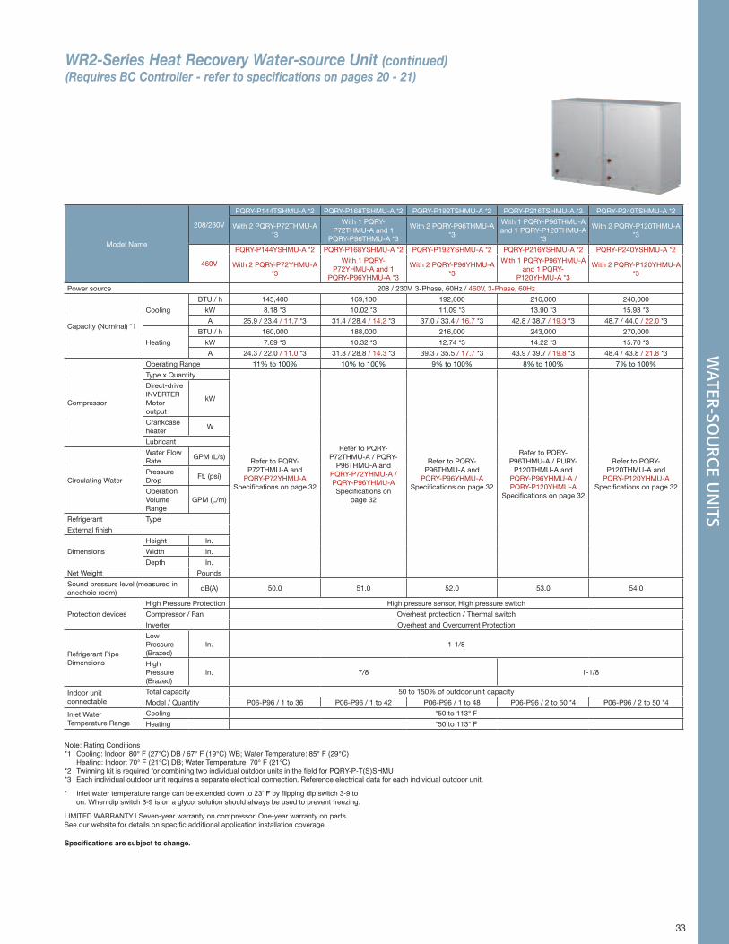
33
WR2-Series Heat Recovery Water-source Unit (continued) (Requires BC Controller - refer to specifications on pages 20 - 21)
WATER-SO
URC
E UN
ITS
Model Name
208/230V
PQRY-P144TSHMU-A *2 PQRY-P168TSHMU-A *2 PQRY-P192TSHMU-A *2 PQRY-P216TSHMU-A *2 PQRY-P240TSHMU-A *2
With 2 PQRY-P72THMU-A *3
With 1 PQRY-P72THMU-A and 1
PQRY-P96THMU-A *3
With 2 PQRY-P96THMU-A *3
With 1 PQRY-P96THMU-A and 1 PQRY-P120THMU-A
*3
With 2 PQRY-P120THMU-A *3
460V
PQRY-P144YSHMU-A *2 PQRY-P168YSHMU-A *2 PQRY-P192YSHMU-A *2 PQRY-P216YSHMU-A *2 PQRY-P240YSHMU-A *2
With 2 PQRY-P72YHMU-A *3
With 1 PQRY-P72YHMU-A and 1
PQRY-P96YHMU-A *3
With 2 PQRY-P96YHMU-A *3
With 1 PQRY-P96YHMU-A and 1 PQRY-
P120YHMU-A *3
With 2 PQRY-P120YHMU-A *3
Power source 208 / 230V, 3-Phase, 60Hz / 460V, 3-Phase, 60Hz
Capacity (Nominal) *1
Cooling
BTU / h 145,400 169,100 192,600 216,000 240,000
kW 8.18 *3 10.02 *3 11.09 *3 13.90 *3 15.93 *3
A 25.9 / 23.4 / 11.7 *3 31.4 / 28.4 / 14.2 *3 37.0 / 33.4 / 16.7 *3 42.8 / 38.7 / 19.3 *3 48.7 / 44.0 / 22.0 *3
Heating
BTU / h 160,000 188,000 216,000 243,000 270,000
kW 7.89 *3 10.32 *3 12.74 *3 14.22 *3 15.70 *3
A 24.3 / 22.0 / 11.0 *3 31.8 / 28.8 / 14.3 *3 39.3 / 35.5 / 17.7 *3 43.9 / 39.7 / 19.8 *3 48.4 / 43.8 / 21.8 *3
Compressor
Operating Range 11% to 100% 10% to 100% 9% to 100% 8% to 100% 7% to 100%
Type x Quantity
Refer to PQRY-P72THMU-A and
PQRY-P72YHMU-A Specifications on page 32
Refer to PQRY-P72THMU-A / PQRY-
P96THMU-A and PQRY-P72YHMU-A / PQRY-P96YHMU-A Specifications on
page 32
Refer to PQRY-P96THMU-A and
PQRY-P96YHMU-A Specifications on page 32
Refer to PQRY-P96THMU-A / PURY-
P120THMU-A and PQRY-P96YHMU-A / PQRY-P120YHMU-A
Specifications on page 32
Refer to PQRY-P120THMU-A and
PQRY-P120YHMU-A Specifications on page 32
Direct-drive INVERTER Motor output
kW
Crankcase heater
W
Lubricant
Circulating Water
Water Flow Rate
GPM (L/s)
Pressure Drop
Ft. (psi)
Operation Volume Range
GPM (L/m)
Refrigerant Type
External finish
Dimensions
Height In.
Width In.
Depth In.
Net Weight Pounds
Sound pressure level (measured in anechoic room)
dB(A) 50.0 51.0 52.0 53.0 54.0
Protection devices
High Pressure Protection High pressure sensor, High pressure switch
Compressor / Fan Overheat protection / Thermal switch
Inverter Overheat and Overcurrent Protection
Refrigerant Pipe Dimensions
Low Pressure (Brazed)
In. 1-1/8
High Pressure (Brazed)
In. 7/8 1-1/8
Indoor unitconnectable
Total capacity 50 to 150% of outdoor unit capacity
Model / Quantity P06-P96 / 1 to 36 P06-P96 / 1 to 42 P06-P96 / 1 to 48 P06-P96 / 2 to 50 *4 P06-P96 / 2 to 50 *4
Inlet Water Temperature Range
Cooling *50 to 113° F
Heating *50 to 113° F
Note: Rating Conditions*1 Cooling: Indoor: 80° F (27°C) DB / 67° F (19°C) WB; Water Temperature: 85° F (29°C) Heating: Indoor: 70° F (21°C) DB; Water Temperature: 70° F (21°C)*2 TwinningkitisrequiredforcombiningtwoindividualoutdoorunitsinthefieldforPQRY-P-T(S)SHMU*3 Each individual outdoor unit requires a separate electrical connection. Reference electrical data for each individual outdoor unit.
* Inlet water temperature range can be extended down to 23°Fbyflippingdipswitch3-9to on . When dip switch 3-9 is on a glycol solution should always be used to prevent freezing .
LIMITED WARRANTY | Seven-year warranty on compressor. One-year warranty on parts. See our website for details on specific additional application installation coverage.
Specifications are subject to change.
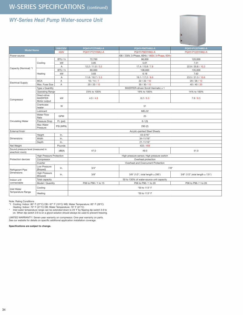
34
W-SERIES SPECIFICATIONS (continued)
WY-Series Heat Pump Water-source Unit
Model Name208/230V PQHY-P72THMU-A PQHY-P96THMU-A PQHY-P120THMU-A
460V PQHY-P72YHMU-A PQHY-P96YHMU-A PQHY-P120YHMU-A
Power source 208 / 230V, 3-Phase, 60Hz / 460V, 3-Phase, 60Hz
Capacity (Nominal) *1
Cooling
BTU / h 72,700 96,000 120,000
kW 3.85 5.61 7.51
A 12.2 / 11.0 / 5.5 17.4 / 15.8 / 7.8 22.9 / 20.8 / 10.3
Heating
BTU / h 80,000 108,000 135,000
kW 3.83 6.18 7.62
A 11.8 / 10.7 / 5.3 19.1 / 17.2 / 8.6 23.5 / 21.3 / 10.6
Electrical SupplyMCA A 16 / 14 / 7 22 / 22 / 10 29 / 26 / 13
Max. Fuse Size A 20 / 20 / 15 30 / 30 / 15 40 / 40 / 20
Compressor
Type x Quantity INVERTER-driven Scroll Hermetic x 1
Operating Range 23% to 100% 19% to 100% 14% to 100%
Direct-drive INVERTER Motor output
kW 4.5 / 4.6 6.2 / 6.3 7.9 / 8.5
Crankcase heater
W 51
Lubricant MEL32
Circulating Water
Water Flow Rate
GPM 25
Pressure Drop Ft. (psi) 6 / (3)
Max Water Pressure
PSI (MPA) 290 (2)
External finish Acrylic-painted Steel Sheets
Dimensions
Height In. 43-5/16"
Width In. 34-11/16"
Depth In. 21-11/16"
Net Weight Pounds 433 / 459
Sound pressure level (measured in anechoic room)
dB(A) 47.0 49.0 51.0
Protection devices
High Pressure Protection High pressure sensor, High pressure switch
Compressor Overheat protection
Inverter Overheat and Overcurrent Protection
Refrigerant Pipe Dimensions
Low Pressure (Brazed)
In. 3/4" 7/8"
High Pressure (Brazed)
In. 3/8" 3/8" (1/2", total length ≥ 295') 3/8" (1/2",total length ≥ 131')
Indoor unitconnectable
Total capacity 50 to 130% of water-source unit capacity
Model / Quantity P06 to P96 / 1 to 15 P06 to P96 / 1 to 20 P06 to P96 / 1 to 26
Inlet Water Temperature Range
Cooling *50 to 113° F
Heating *50 to 113° F
Note: Rating Conditions*1 Cooling: Indoor: 80° F (27°C) DB / 67° F (19°C) WB; Water Temperature: 85° F (29°C) Heating: Indoor: 70° F (21°C) DB; Water Temperature: 70° F (21°C)* Inlet water temperature range can be extended down to 23°Fbyflippingdipswitch3-9to on . When dip switch 3-9 is on a glycol solution should always be used to prevent freezing .
LIMITED WARRANTY | Seven-year warranty on compressor. One-year warranty on parts. See our website for details on specific additional application installation coverage.
Specifications are subject to change.
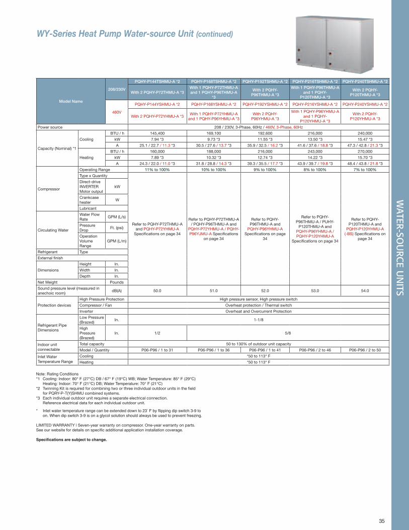
35
WY-Series Heat Pump Water-source Unit (continued)
Model Name
208/230V
PQHY-P144TSHMU-A *2 PQHY-P168TSHMU-A *2 PQHY-P192TSHMU-A *2 PQHY-P216TSHMU-A *2 PQHY-P240TSHMU-A *2
With 2 PQHY-P72THMU-A *3With 1 PQHY-P72THMU-A and 1 PQHY-P96THMU-A
*3
With 2 PQHY-P96THMU-A *3
With 1 PQHY-P96THMU-A and 1 PQHY-
P120THMU-A *3
With 2 PQHY-P120THMU-A *3
460V
PQHY-P144YSHMU-A *2 PQHY-P168YSHMU-A *2 PQHY-P192YSHMU-A *2 PQHY-P216YSHMU-A *2 PQHY-P240YSHMU-A *2
With 2 PQHY-P72YHMU-A *3With 1 PQHY-P72YHMU-A
and 1 PQHY-P96YHMU-A *3With 2 PQHY-
P96YHMU-A *3
With 1 PQHY-P96YHMU-A and 1 PQHY-
P120YHMU-A *3
With 2 PQHY-P120YHMU-A *3
Power source 208 / 230V, 3-Phase, 60Hz / 460V, 3-Phase, 60Hz
Capacity (Nominal) *1
Cooling
BTU / h 145,400 169,100 192,600 216,000 240,000
kW 7.94 *3 9.73 *3 11.55 *3 13.50 *3 15.47 *3
A 25.1 / 22.7 / 11.3 *3 30.5 / 27.6 / 13.7 *3 35.9 / 32.5 / 16.2 *3 41.6 / 37.6 / 18.8 *3 47.3 / 42.8 / 21.3 *3
Heating
BTU / h 160,000 188,000 216,000 243,000 270,000
kW 7.89 *3 10.32 *3 12.74 *3 14.22 *3 15.70 *3
A 24.3 / 22.0 / 11.0 *3 31.8 / 28.8 / 14.3 *3 39.3 / 35.5 / 17.7 *3 43.9 / 39.7 / 19.8 *3 48.4 / 43.8 / 21.8 *3
Compressor
Operating Range 11% to 100% 10% to 100% 9% to 100% 8% to 100% 7% to 100%
Type x Quantity
Refer to PQHY-P72THMU-A and PQHY-P72YHMU-A
Specifications on page 34
Refer to PQHY-P72THMU-A / PQHY-P96THMU-A and
PQHY-P72YHMU-A / PQHY-P96YJMU-A Specifications
on page 34
Refer to PQHY-P96THMU-A and
PQHY-P96YHMU-A Specifications on page
34
Refer to PQHY-P96THMU-A / PUHY-
P120THMU-A and PQHY-P96YHMU-A / PQHY-P120YHMU-A
Specifications on page 34
Refer to PQHY-P120THMU-A and
PQHY-P120YHMU-A (-BS) Specifications on
page 34
Direct-drive INVERTER Motor output
kW
Crankcase heater
W
Lubricant
Circulating Water
Water Flow Rate
GPM (L/s)
Pressure Drop
Ft. (psi)
Operation Volume Range
GPM (L/m)
Refrigerant Type
External finish
Dimensions
Height In.
Width In.
Depth In.
Net Weight Pounds
Sound pressure level (measured in anechoic room)
dB(A) 50.0 51.0 52.0 53.0 54.0
Protection devices
High Pressure Protection High pressure sensor, High pressure switch
Compressor / Fan Overheat protection / Thermal switch
Inverter Overheat and Overcurrent Protection
Refrigerant Pipe Dimensions
Low Pressure (Brazed)
In. 1-1/8
High Pressure (Brazed)
In. 1/2 5/8
Indoor unitconnectable
Total capacity 50 to 130% of outdoor unit capacity
Model / Quantity P06-P96 / 1 to 31 P06-P96 / 1 to 36 P06-P96 / 1 to 41 P06-P96 / 2 to 46 P06-P96 / 2 to 50
Inlet Water Temperature Range
Cooling *50 to 113° F
Heating *50 to 113° F
Note: Rating Conditions*1 Cooling: Indoor: 80° F (27°C) DB / 67° F (19°C) WB; Water Temperature: 85° F (29°C) Heating: Indoor: 70° F (21°C) DB; Water Temperature: 70° F (21°C)*2 Twinning Kit is required for combining two or three individual outdoor units in the field for PQRY-P-T(Y)SHMU combined systems.*3 Each individual outdoor unit requires a separate electrical connection. Reference electrical data for each individual outdoor unit.
* Inlet water temperature range can be extended down to 23°Fbyflippingdipswitch3-9to on . When dip switch 3-9 is on a glycol solution should always be used to prevent freezing .
LIMITED WARRANTY | Seven-year warranty on compressor. One-year warranty on parts. See our website for details on specific additional application installation coverage.
Specifications are subject to change.
WATER-SO
URC
E UN
ITS
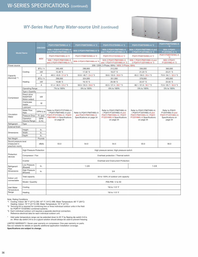
36
W-SERIES SPECIFICATIONS (continued)
WY-Series Heat Pump Water-source Unit (continued)
Model Name
208/230VPQHY-P264TSHMU-A *2 PQHY-P288TSHMU-A *2 PQHY-P312TSHMU-A *2 PQHY-P336TSHMU-A *2
PQHY-P360TSHMU-A *2
With 1 PQHY-P72THMU-A and 2 PQHY-P96THMU-A *3
With 3 PQHY-P96THMU-A *3With 2 PQHY-P96THMU-A
and 1 PQHY-P120THMU-A *3With 1 PQHY-P96THMU-A and
2 PQHY-P120THMU-A *3With 3 PQHY-
P120YHMU-A *3
460VPQHY-P264YHMU-A *2 PQHY-P288YSHMU-A *2 PQHY-P312YSHMU-A *2 PQHY-P336YSHMU-A *2
PQHY-P360YSHMU-A *2
With 1 PQHY-P96YHMU-A and 2 PQHY-P96YHMU-A *3
With 3 PQHY-P96YHMU-A *3With 2 PQHY-P96YHMU-A
and 1 PQHY-P120YHMU-A *3With 1 PQHY-P96YHMU-A and
2 PQHY-P120YHMU-A *3With 3 PQHY-
P120YHMU-A *3
Power source 208 / 230V, 3-Phase, 60Hz / 460V, 3-Phase, 60Hz
Capacity (Nominal) *1
Cooling
BTU / h 265,400 288,900 312,200 336,000 360,000
kW 15.49 *3 17.32 *3 19.27 *3 21.23 *3 23.21 *3
A 48.5 / 43.8 / 21.9 *3 53.8 / 48.7 / 24.3 *3 59.6 / 53.9 / 26.9 *3 65.2 / 59.0 / 29.4 *3 70.9 / 64.1 / 32.0 *3
Heating
BTU / h 296,000 324,000 351,000 378,000 405,000
kW 16.68 *3 19.10 *3 20.58 *3 22.07 *3 23.55 *3
A 51.4 / 46.5 / 23.2 *3 58.9 / 53.3 / 26.6 *3 63.5 / 57.4 / 28.7 *3 68.1 / 61.6 / 30.7 *3 72.6 / 65.7 / 32.8 *3
Compressor
Operating Range 7% to 100% 6% to 100% 6% to 100% 5% to 100% 5% to 100%
Type x Quantity
Refer to PQHY-P72THMU-A / PQHY-P96THMU-A and
PQHY-P72YHMU-A / PQHY-P96YHMU-A Specifications
on page 34
Refer to PQHY-P96THMU-A and PQHY-P96YHMU-A
Specifications on page 34
Refer to PQHY-P96THMU-A / PQHY-P120THMU-A and
PQHY-P96YHMU-A / PQHY-P120YHMU-A Specifications
on page 34
Refer to PQHY-P96THMU-A / PQHY-P120THMU-A and
PQHY-P96YHMU-A / PQHY-P120YHMU-A Specifications
on page 34
Refer to PQHY-P120THMU-A and
PQHY-P120YHMU-A Specifications on
page 34
Direct-drive INVERTER Motor output
kW
Crankcase heater
W
Lubricant
Circulation Water
Water Flow Rate
GPM (L/s)
Pressure Drop Ft. (psi)
Operation Volume Range
GPM (L/m)
Refrigerant Type
External finish
Dimensions
Height In.
Width In.
Depth In.
Net Weight Pounds
Sound pressure level (measured in anechoic room)
dB(A) 53.0 54.0 54.5 55.0 56.0
Protection devices
High Pressure Protection High pressure sensor, High pressure switch
Compressor / Fan Overheat protection / Thermal switch
Inverter Overheat and Overcurrent Protection
Refrigerant Pipe Dimensions
Low Pressure (Brazed)
In. 1-3/8 1-5/8
High Pressure (Brazed)
In. 3/4
Indoor unitconnectable
Total capacity 50 to 130% of outdoor unit capacity
Model / Quantity P06-P96 / 2 to 50
Inlet Water Temperature Range
Cooling *50 to 113° F
Heating *50 to 113° F
Note: Rating Conditions*1 Cooling: Indoor: 80° F (27°C) DB / 67° F (19°C) WB; Water Temperature: 85° F (29°C) Heating: Indoor: 70° F (21°C) DB; Water Temperature: 70° F (21°C)*2 Twinning Kit is required for combining two or three individual outdoor units in the field for PQRY-P-T(Y)SHMU combined systems.*3 Each individual outdoor unit requires a separate electrical connection. Reference electrical data for each individual outdoor unit.
* Inlet water temperature range can be extended down to 23°Fbyflippingdipswitch3-9to on . When dip switch 3-9 is on a glycol solution should always be used to prevent freezing .
LIMITED WARRANTY | Seven-year warranty on compressor. One-year warranty on parts. See our website for details on specific additional application installation coverage. Specifications are subject to change.
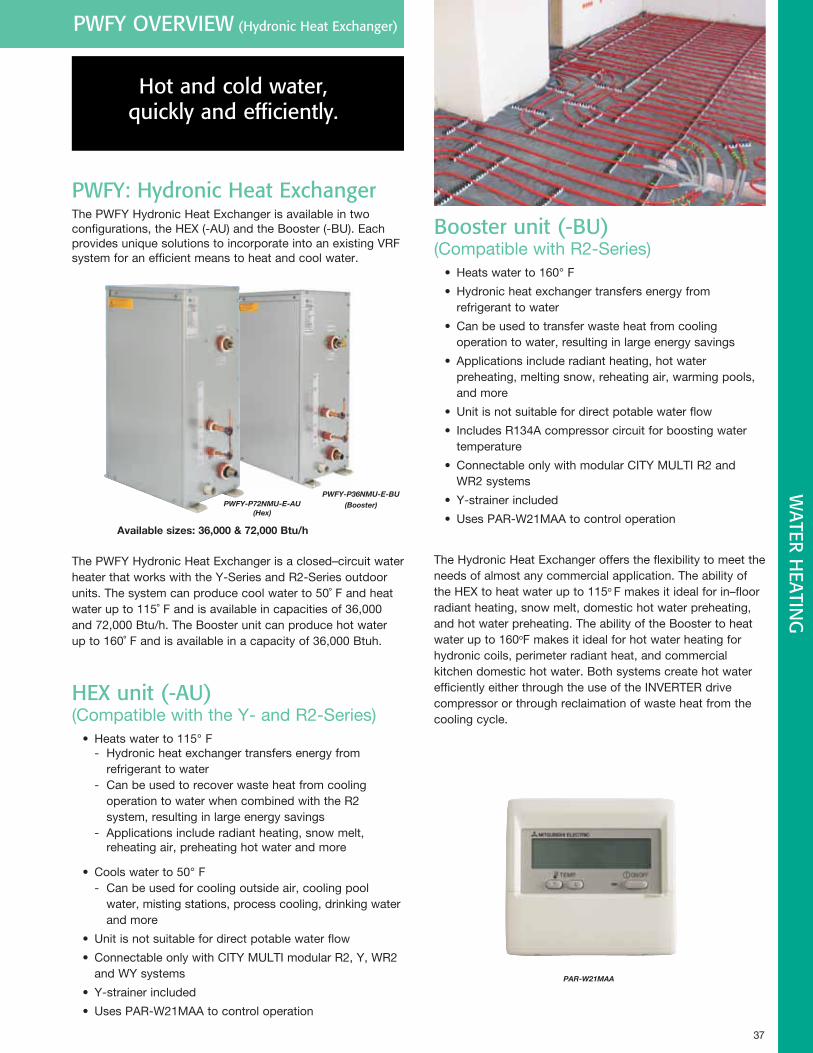
37
PWFY OVERVIEW (Hydronic Heat Exchanger)
Hot and cold water, quickly and efficiently.
PWFY: Hydronic Heat ExchangerThe PWFY Hydronic Heat Exchanger is available in two configurations, the HEX (-AU) and the Booster (-BU). Each provides unique solutions to incorporate into an existing VRF system for an efficient means to heat and cool water.
The PWFY Hydronic Heat Exchanger is a closed–circuit water heater that works with the Y-Series and R2-Series outdoor units. The system can produce cool water to 50˚ F and heat water up to 115˚ F and is available in capacities of 36,000 and 72,000 Btu/h. The Booster unit can produce hot water up to 160˚ F and is available in a capacity of 36,000 Btuh.
HEX unit (-AU) (Compatible with the Y- and R2-Series)
• Heats water to 115° F - Hydronic heat exchanger transfers energy from refrigerant to water - Can be used to recover waste heat from cooling operation to water when combined with the R2 system, resulting in large energy savings - Applications include radiant heating, snow melt, reheating air, preheating hot water and more
• Cools water to 50° F - Can be used for cooling outside air, cooling pool water, misting stations, process cooling, drinking water and more
• Unit is not suitable for direct potable water flow
• Connectable only with CITY MULTI modular R2, Y, WR2 and WY systems
• Y-strainer included
• Uses PAR-W21MAA to control operation
PAR-W21MAA
WATER H
EATING
PWFY-P72NMU-E-AU(Hex)
PWFY-P36NMU-E-BU(Booster)
Availablesizes:36,000&72,000Btu/h
Booster unit (-BU) (Compatible with R2-Series)
• Heats water to 160° F
• Hydronic heat exchanger transfers energy from refrigerant to water
• Can be used to transfer waste heat from cooling operation to water, resulting in large energy savings
• Applications include radiant heating, hot water preheating, melting snow, reheating air, warming pools, and more
• Unit is not suitable for direct potable water flow
• Includes R134A compressor circuit for boosting water temperature
• Connectable only with modular CITY MULTI R2 and WR2 systems
• Y-strainer included
• Uses PAR-W21MAA to control operation
The Hydronic Heat Exchanger offers the flexibility to meet the needs of almost any commercial application. The ability of the HEX to heat water up to 115o F makes it ideal for in–floor radiant heating, snow melt, domestic hot water preheating, and hot water preheating. The ability of the Booster to heat water up to 160oF makes it ideal for hot water heating for hydronic coils, perimeter radiant heat, and commercial kitchen domestic hot water. Both systems create hot water efficiently either through the use of the INVERTER drive compressor or through reclaimation of waste heat from the cooling cycle.
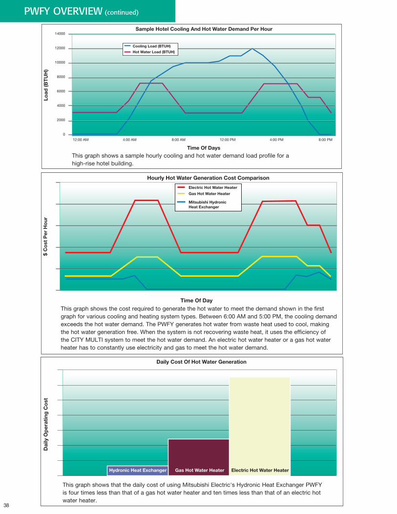
38
PWFY OVERVIEW (continued)
12:00 AM 4:00 AM 8:00 AM 12:00 PM 4:00 PM 8:00 PM
Load
(BT
UH
)
Sample Hotel Cooling And Hot Water Demand Per Hour
Time Of Days
10000
12000
14000
8000
6000
4000
2000
0
Cooling Load (BTUH)
Hot Water Load (BTUH)
Electric Hot Water Heater
Gas Hot Water Heater
Mitsubishi Hydronic Heat Exchanger
$ C
ost
Per
Ho
ur
Hourly Hot Water Generation Cost Comparison
Time Of Day
Hydronic Heat Exchanger Gas Hot Water Heater Electric Hot Water Heater
Dai
ly O
per
atin
g C
ost
Daily Cost Of Hot Water Generation
This graph shows a sample hourly cooling and hot water demand load profile for a high-rise hotel building.
This graph shows the cost required to generate the hot water to meet the demand shown in the first graph for various cooling and heating system types. Between 6:00 AM and 5:00 PM, the cooling demand exceeds the hot water demand. The PWFY generates hot water from waste heat used to cool, making the hot water generation free. When the system is not recovering waste heat, it uses the efficiency of the CITY MULTI system to meet the hot water demand. An electric hot water heater or a gas hot water heater has to constantly use electricity and gas to meet the hot water demand.
This graph shows that the daily cost of using Mitsubishi Electric's Hydronic Heat Exchanger PWFY is four times less than that of a gas hot water heater and ten times less than that of an electric hot water heater.
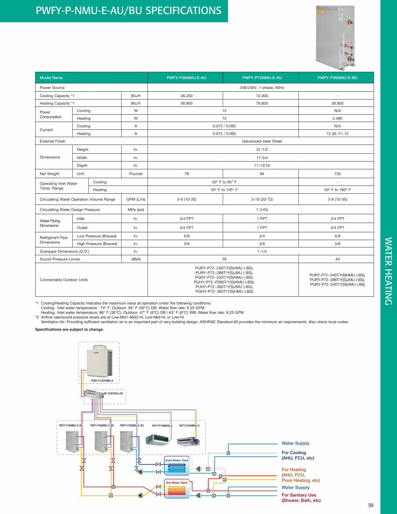
39
Water Supply
Cold Water Tank
Hot Water Tank
For Cooling(AHU, FCU, etc)
For Heating(AHU, FCU,Floor Heating, etc)
For Sanitary Use(Shower, Bath, etc)
Water Supply
PWFY-P38NMU-E-BU PWFY-P36NMU-E-BU
BC CONTROLLER
PURY-P120YHMU-A
PWFY-P36NMU-E-BU PEFY-P15NMHU-E PEFY-P24NMSU-E
PWFY-P-NMU-E-AU/BU SPECIFICATIONSW
ATER HEATIN
G
Model Name PWFY-P36NMU-E-AU PWFY-P72NMU-E-AU PWFY-P36NMU-E-BU
Power Source 208/230V, 1-phase, 60Hz
Cooling Capacity *1 Btu/h 36,200 72,000 -
Heating Capacity *1 Btu/h 39,900 79,800 39,900
Power Consumption
Cooling W 15 N/A
Heating W 15 2,480
CurrentCooling A 0.072 / 0.065 N/A
Heating A 0.072 / 0.065 12.30 /11.12
External Finish Galvanized-steel Sheet
Dimensions
Height In. 31-1/2
Width In. 17-3/4
Depth In. 11-13/16
Net Weight Unit Pounds 78 84 133
Operating Inlet Water Temp. Range
Cooling 50° F to 95° F -
Heating 50° F to 105° F 50° F to 160° F
Circulating Water Operation Volume Range GPM (L/m) 3-9 (10-35) 5-18 (20-72) 3-9 (10-35)
Circulating Water Design Pressure MPa (psi) 1 (145)
Water Piping Dimensions
Inlet In. 3/4 FPT 1 FPT 3/4 FPT
Outlet In. 3/4 FPT 1 FPT 3/4 FPT
Refrigerant Pipe Dimensions
Low Pressure (Brazed) In. 5/8 3/4 5/8
High Pressure (Brazed) In. 3/8 3/8 3/8
Drainpipe Dimensions (O.D.) In. 1-1/4
Sound Pressure Levels dB(A) 29 44
Connectable Outdoor Units
PURY-P72~240T/Y(S)HMU (-BS),PURY-P72~288T/Y(S)JMU (-BS),PQRY-P72~240T/Y(S)HMU (-BS),
PUHY-P72~P360T/Y(S)HMU (-BS),PUHY-P72~360T/Y(S)JMU (-BS),PQHY-P72~360T/Y(S)HMU (-BS)
PURY-P72~240T/Y(S)HMU (-BS),PURY-P72~288T/Y(S)JMU (-BS),PQRY-P72~240T/Y(S)HMU (-BS)
*1 Cooling/Heating Capacity indicates the maximum value at operation under the following conditions: Cooling: Inletwatertemperature:74°F;Outdoor:95°F(35°C)DB;Waterflowrate:9.25GPM Heating:Inletwatertemperature:86°F(30°C);Outdoor:47°F(8°C)DB/43°F(6°C)WB;Waterflowrate:9.25GPM*2 Airflowrate/soundpressurelevelsareatLow-Mid1-Mid2-Hi,Low-Mid-Hi,orLow-Hi VentilationAir:Providingsufficientventilationairisanimportantpartofverybuildingdesign.ASHRAEStandard62providestheminimumairrequirements.Alsochecklocalcodes.
Specifications are subject to change.
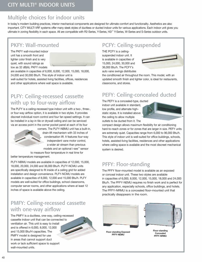
40
Multiple choices for indoor unitsIn today’s modern building practices, interior mechanical components are designed for ultimate comfort and functionality. Aesthetics are also important. CITY MULTI VRF systems offer many sleek styles of ductless or ducted indoor units for various applications. Each indoor unit gives you ultimate in zoning flexibility in each space. All are compatible with R2-Series, Y-Series, H2i™ Y-Series, W-Series and S-Series outdoor units.
CITY MULTI® INDOOR UNITS
PKFY: Wall-mountedThe PKFY wall-mounted indoor unit has a smooth front and lighter color finish and is very quiet, with sound ratings as low as 32 dB(A). PKFY models are available in capacities of 6,000, 8,000, 12,000, 15,000, 18,000, 24,000 and 30,000 Btu/h. This style of indoor unit is well-suited for hotels, assisted living facilities, offices, residences and other applications where wall space is available.
PLFY: Ceiling-recessed cassette with up to four-way airflowThe PLFY is a ceiling-recessed type indoor unit with a two-, three-, or four-way airflow option, it is available in two styles. It provides discreet individual room control and four fan speed settings. It can be installed in a lay-in tile or drywall ceiling and can be serviced via an access point in the corner pocket panel at each of its four
corners. The PLFY-NBMU unit has a built-in, drain-lift mechanism with 33 inches of
condensation lift. It features four-way independent vane motor control, a wider air stream than previous
models and an optional i-see™ sensor to measure floor temperature in real time for
better temperature management.
PLFY-NBMU models are available in capacities of 12,000, 15,000, 18,000, 20,000, 24,000 and 36,000 Btu/h. PLFY-NCMU units are specifically designed to fit inside of a ceiling grid for added installation and design convenience. PLFY-NCMU models are available in capacities of 8,000, 12,000 and 15,000 Btu/h. PLFY models are well-suited for office buildings, school classrooms, computer server rooms, and other applications where at least 12 inches of space is available above the ceiling.
PMFY: Ceiling-recessed cassette with one-way airflowThe PMFY is a ductless, one-way, ceiling-recessed cassette indoor unit that can be connected to ventilation air. This unit is easy to install and is offered in 6,000, 8,000, 12,000 and 15,000 Btu/H capacities. The PMFY model is designed for use in areas that cannot support duct work or lack sufficient space to support wall-mounted units.
PCFY: Ceiling-suspendedTHE PCFY is a ceiling- suspended indoor unit. It is available in capacities of 15,000, 24,000, 30,000 and 36,000 Btu/h. The PCFY’s auto vane swings distributes the conditioned air throughout the room. This model, with an updated smooth finish and lighter color, is ideal for restaurants, classrooms, and stores.
PEFY: Ceiling-concealed ductedThe PEFY is a concealed-type, ducted indoor unit available in standard, low profile, and alternate high– static styles. It is installed above the ceiling to allow multiple outlets to be ducted from it. The compact design allows maximum flexibility for air conditioning hard-to-reach zones or for zones that are larger in size. PEFY units are extremely quiet. Capacities range from 6,000 to 96,000 Btu/h. This style of indoor unit is well-suited for office buildings, schools, hotels, assisted-living facilities, residences and other applications where ceiling space is available and the most discreet mechanical
system is desired.
PFFY: Floor-standingThe PFFY floor-mounted model is available as an exposed or conceal indoor unit. These two styles are available in capacities of 6,000, 8,000, 12,000, 15,000, 18,000 and 24,000 Btu/h. The PFFY-NEMU requires no finish work and is perfect for any application, especially schools, office buildings, and hotels. The PFFY-NRMU is a concealed floor-mounted unit that practically disappears in the room.
Floor-standingExposedPFFY-NEMU
Floor-standingConcealed
PFFY-NRMU
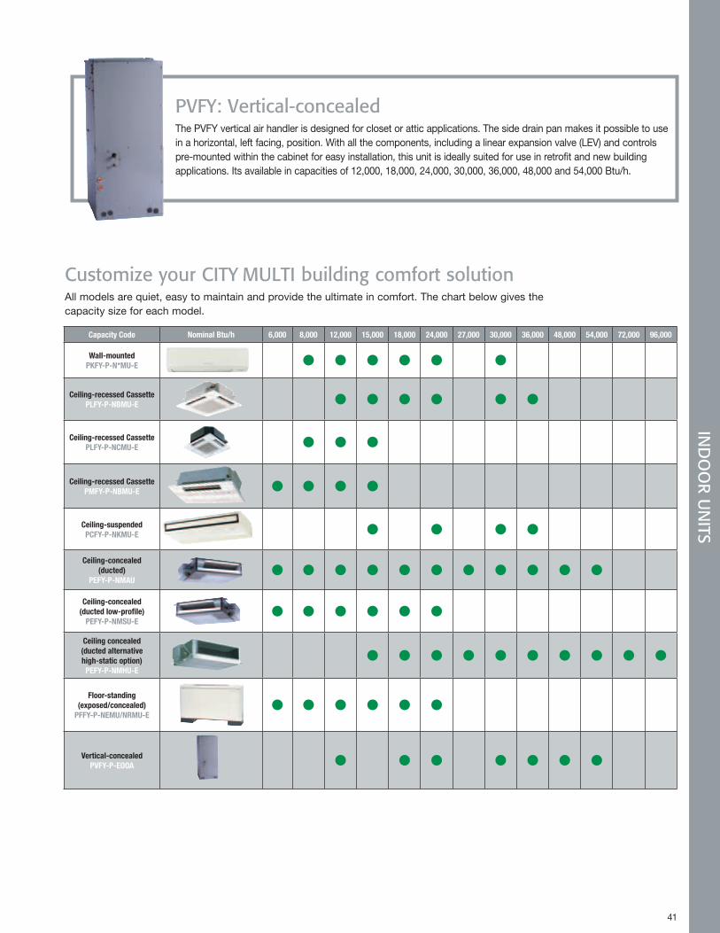
41 41
IND
OO
R UN
ITS
PVFY: Vertical-concealedThe PVFY vertical air handler is designed for closet or attic applications. The side drain pan makes it possible to use in a horizontal, left facing, position. With all the components, including a linear expansion valve (LEV) and controls pre-mounted within the cabinet for easy installation, this unit is ideally suited for use in retrofit and new building applications. Its available in capacities of 12,000, 18,000, 24,000, 30,000, 36,000, 48,000 and 54,000 Btu/h.
Customize your CITY MULTI building comfort solutionAll models are quiet, easy to maintain and provide the ultimate in comfort. The chart below gives the capacity size for each model.
Capacity Code Nominal Btu/h 6,000 8,000 12,000 15,000 18,000 24,000 27,000 30,000 36,000 48,000 54,000 72,000 96,000
Wall-mounted PKFY-P-N*MU-E
Ceiling-recessed Cassette PLFY-P-NBMU-E
Ceiling-recessed Cassette PLFY-P-NCMU-E
Ceiling-recessed Cassette PMFY-P-NBMU-E
Ceiling-suspended PCFY-P-NKMU-E
Ceiling-concealed (ducted)
PEFY-P-NMAU
Ceiling-concealed (ducted low-profile)
PEFY-P-NMSU-E
Ceiling concealed (ducted alternative high-static option) PEFY-P-NMHU-E
Floor-standing (exposed/concealed)
PFFY-P-NEMU/NRMU-E
Vertical-concealed PVFY-P-EOOA
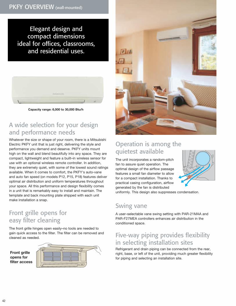
42
Capacityrange:6,000to30,000Btu/h
A wide selection for your design and performance needsWhatever the size or shape of your room, there is a Mitsubishi Electric PKFY unit that is just right, delivering the style and performance you demand and deserve. PKFY units mount high on the wall and blend beautifully into any space. They are compact, lightweight and feature a built–in wireless sensor for use with an optional wireless remote controller. In addition, they are extremely quiet, with some of the lowest sound ratings available. When it comes to comfort, the PKFY's auto-vane and auto fan speed (on models P12, P15, P18) features deliver optimal air distribution and uniform temperatures throughout your space. All this performance and design flexibility comes in a unit that is remarkably easy to install and maintain. The template and back mounting plate shipped with each unit make installation a snap.
Front grille opens for easy filter cleaningThe front grille hinges open easily–no tools are needed to gain quick access to the filter. The filter can be removed and cleaned as needed.
Frontgrilleopensforfilteraccess
PKFY OVERVIEW (wall-mounted)
Elegant design and compact dimensions
ideal for offices, classrooms, and residential uses.
Operation is among the quietest availableThe unit incorporates a random-pitch fan to assure quiet operation. The optimal design of the airflow passage features a small fan diameter to allow for a compact installation. Thanks to practical casing configuration, airflow generated by the fan is distributed uniformly. This design also suppresses condensation.
Swing vaneA user–selectable vane swing setting with PAR-21MAA and PAR-F27MEA controllers enhances air distribution in the conditioned space.
Five-way piping provides flexibility in selecting installation sitesRefrigerant and drain piping can be connected from the rear, right, base, or left of the unit, providing much greater flexibility for piping and selecting an installation site.
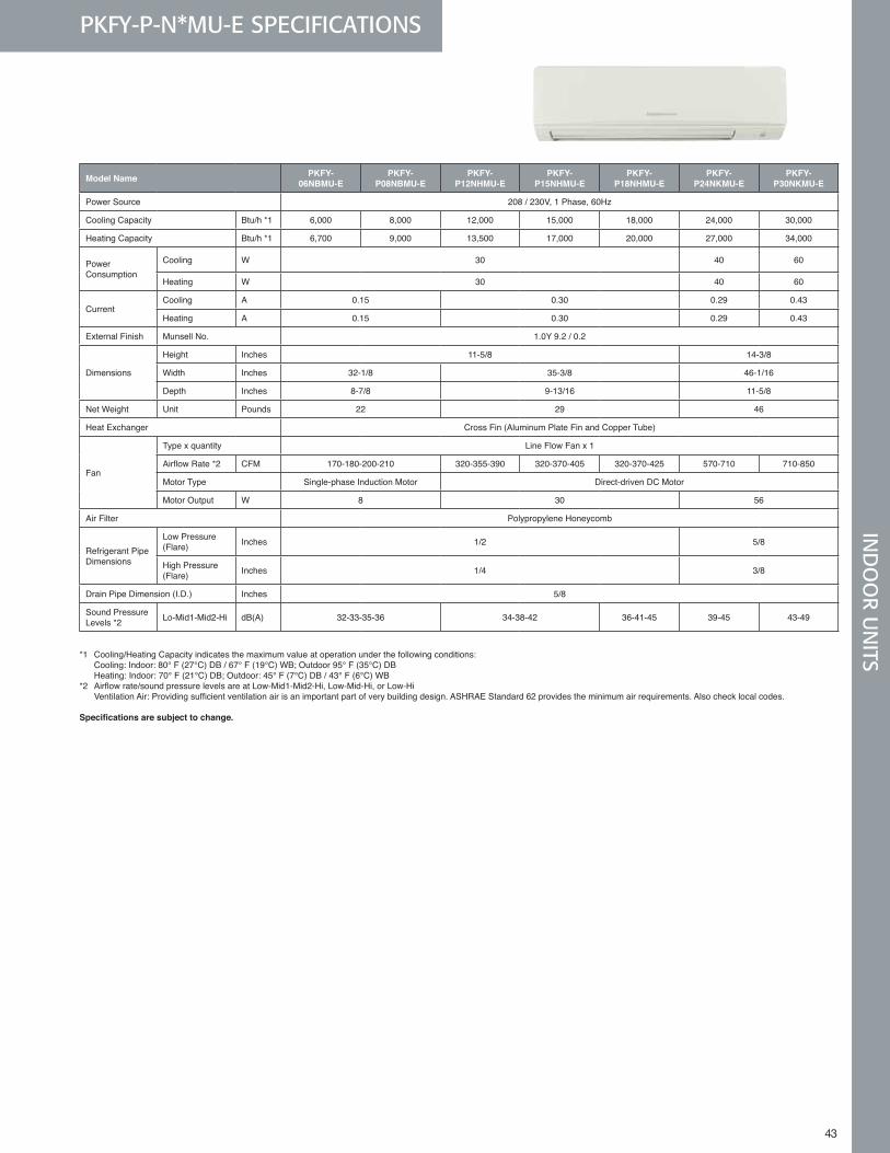
43
PKFY-P-N*MU-E SPECIFICATIONS
43
IND
OO
R UN
ITS
Model Name PKFY- 06NBMU-E
PKFY- P08NBMU-E
PKFY-P12NHMU-E
PKFY-P15NHMU-E
PKFY-P18NHMU-E
PKFY- P24NKMU-E
PKFY- P30NKMU-E
Power Source 208 / 230V, 1 Phase, 60Hz
Cooling Capacity Btu/h *1 6,000 8,000 12,000 15,000 18,000 24,000 30,000
Heating Capacity Btu/h *1 6,700 9,000 13,500 17,000 20,000 27,000 34,000
Power Consumption
Cooling W 30 40 60
Heating W 30 40 60
CurrentCooling A 0 .15 0 .30 0 .29 0 .43
Heating A 0 .15 0 .30 0 .29 0 .43
External Finish Munsell No . 1 .0Y 9 .2 / 0 .2
Dimensions
Height Inches 11-5/8 14-3/8
Width Inches 32-1/8 35-3/8 46-1/16
Depth Inches 8-7/8 9-13/16 11-5/8
Net Weight Unit Pounds 22 29 46
Heat Exchanger Cross Fin (Aluminum Plate Fin and Copper Tube)
Fan
Type x quantity Line Flow Fan x 1
AirflowRate*2 CFM 170-180-200-210 320-355-390 320-370-405 320-370-425 570-710 710-850
Motor Type Single-phase Induction Motor Direct-driven DC Motor
Motor Output W 8 30 56
Air Filter Polypropylene Honeycomb
Refrigerant Pipe Dimensions
Low Pressure (Flare) Inches 1/2 5/8
High Pressure (Flare) Inches 1/4 3/8
Drain Pipe Dimension (I .D .) Inches 5/8
Sound Pressure Levels *2 Lo-Mid1-Mid2-Hi dB(A) 32-33-35-36 34-38-42 36-41-45 39-45 43-49
*1 Cooling/Heating Capacity indicates the maximum value at operation under the following conditions: Cooling: Indoor: 80° F (27°C) DB / 67° F (19°C) WB; Outdoor 95° F (35°C) DB Heating: Indoor: 70° F (21°C) DB; Outdoor: 45° F (7°C) DB / 43° F (6°C) WB*2 Airflowrate/soundpressurelevelsareatLow-Mid1-Mid2-Hi,Low-Mid-Hi,orLow-Hi VentilationAir:Providingsufficientventilationairisanimportantpartofverybuildingdesign.ASHRAEStandard62providestheminimumairrequirements.Alsochecklocalcodes.
Specifications are subject to change.
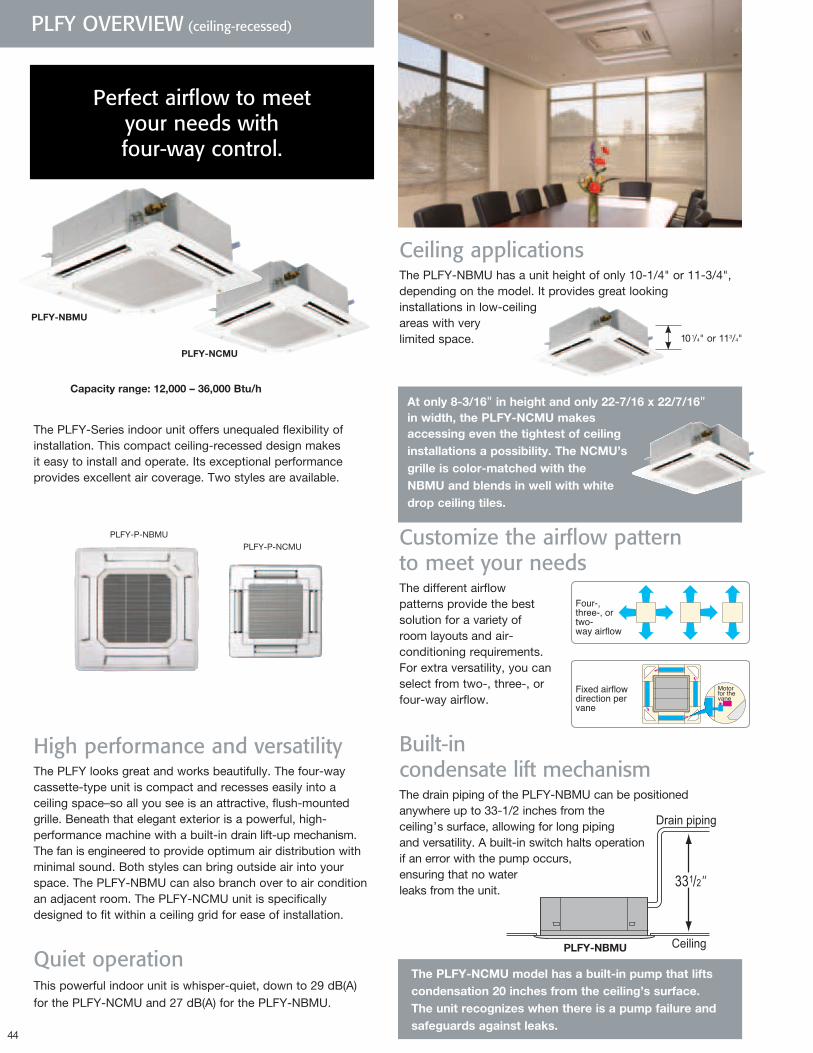
44
PLFY OVERVIEW (ceiling-recessed)
Capacityrange:12,000–36,000Btu/h
PLFY-NBMU
High performance and versatility The PLFY looks great and works beautifully. The four-way cassette-type unit is compact and recesses easily into a ceiling space–so all you see is an attractive, flush-mounted grille. Beneath that elegant exterior is a powerful, high-performance machine with a built-in drain lift-up mechanism. The fan is engineered to provide optimum air distribution with minimal sound. Both styles can bring outside air into your space. The PLFY-NBMU can also branch over to air condition an adjacent room. The PLFY-NCMU unit is specifically designed to fit within a ceiling grid for ease of installation.
Quiet operationThis powerful indoor unit is whisper-quiet, down to 29 dB(A) for the PLFY-NCMU and 27 dB(A) for the PLFY-NBMU.
The PLFY-Series indoor unit offers unequaled flexibility of installation. This compact ceiling-recessed design makes it easy to install and operate. Its exceptional performance provides excellent air coverage. Two styles are available.
PLFY-P-NCMU
25 -5/8“ 37 -7/16“
PLFY-P-NBMU PLFY-P-NCMU
25 -5/8“ 37 -7/16“
PLFY-P-NBMU
Perfect airflow to meet your needs with four-way control.
ThePLFY-NCMUmodelhasabuilt-inpumpthatliftscondensation20inchesfromtheceiling’ssurface.Theunitrecognizeswhenthereisapumpfailureandsafeguardsagainstleaks.
PLFY-NBMU
Customize the airflow pattern to meet your needsThe different airflow patterns provide the best solution for a variety of room layouts and air- conditioning requirements. For extra versatility, you can select from two-, three-, or four-way airflow.
Built-in condensate lift mechanism The drain piping of the PLFY-NBMU can be positioned anywhere up to 33-1/2 inches from the ceiling’s surface, allowing for long piping and versatility. A built-in switch halts operation if an error with the pump occurs, ensuring that no water leaks from the unit.
PLFY-NCMU
Ceiling applicationsThe PLFY-NBMU has a unit height of only 10-1/4" or 11-3/4", depending on the model. It provides great looking installations in low-ceiling areas with very limited space. 101/4" or 113/4"
Atonly8-3/16"inheightandonly22-7/16x22/7/16"inwidth,thePLFY-NCMUmakesaccessingeventhetightestofceilinginstallationsapossibility.TheNCMU’sgrilleiscolor-matchedwiththeNBMUandblendsinwellwithwhitedropceilingtiles.
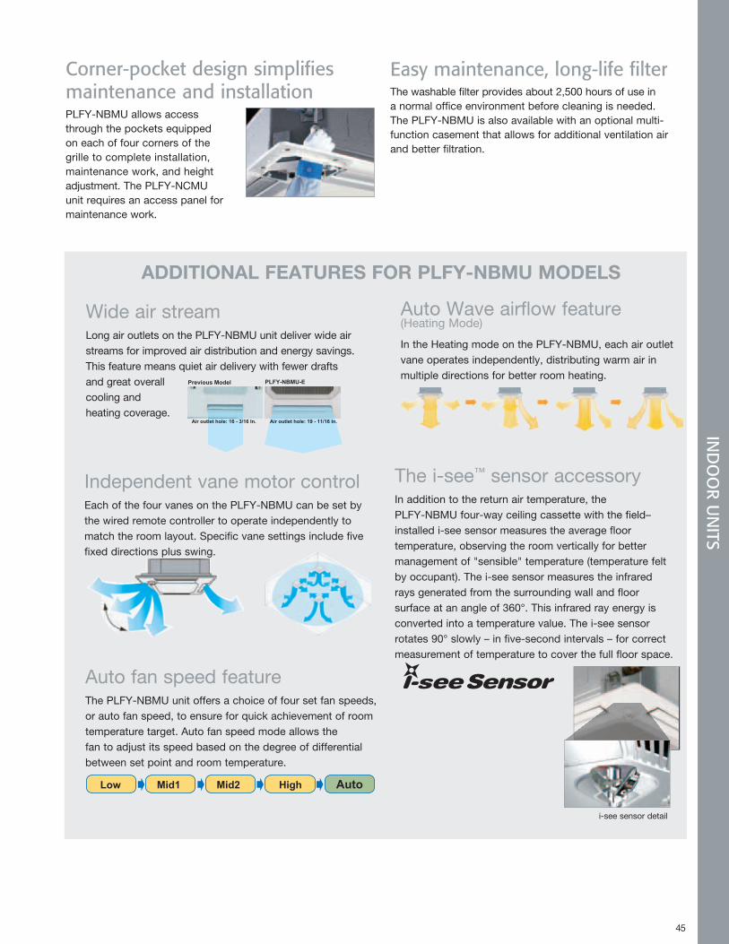
45
Auto Wave airflow feature (Heating Mode)
In the Heating mode on the PLFY-NBMU, each air outlet vane operates independently, distributing warm air in multiple directions for better room heating.
ADDITIONALFEATURESFORPLFY-NBMUMODELS
Corner-pocket design simplifies maintenance and installationPLFY-NBMU allows access through the pockets equipped on each of four corners of the grille to complete installation, maintenance work, and height adjustment. The PLFY-NCMU unit requires an access panel for maintenance work.
45
Wide air streamLong air outlets on the PLFY-NBMU unit deliver wide air streams for improved air distribution and energy savings. This feature means quiet air delivery with fewer drafts and great overall cooling and heating coverage.
Previous Model PLFY-NBMU-E
Air outlet hole: 16 - 3/16 In. Air outlet hole: 19 - 11/16 In.
Independent vane motor controlEach of the four vanes on the PLFY-NBMU can be set by the wired remote controller to operate independently to match the room layout. Specific vane settings include five fixed directions plus swing.
Auto fan speed featureThe PLFY-NBMU unit offers a choice of four set fan speeds, or auto fan speed, to ensure for quick achievement of room temperature target. Auto fan speed mode allows the fan to adjust its speed based on the degree of differential between set point and room temperature. Auto Fan Speed Mode
Low Mid1 Mid2 High Auto
IND
OO
R UN
ITS
i-see sensor detail
Easy maintenance, long-life filterThe washable filter provides about 2,500 hours of use in a normal office environment before cleaning is needed. The PLFY-NBMU is also available with an optional multi-function casement that allows for additional ventilation air and better filtration.
The i-see™ sensor accessory In addition to the return air temperature, the PLFY-NBMU four-way ceiling cassette with the field–installed i-see sensor measures the average floor temperature, observing the room vertically for better management of "sensible" temperature (temperature felt by occupant). The i-see sensor measures the infrared rays generated from the surrounding wall and floor surface at an angle of 360°. This infrared ray energy is converted into a temperature value. The i-see sensor rotates 90° slowly – in five-second intervals – for correct measurement of temperature to cover the full floor space.
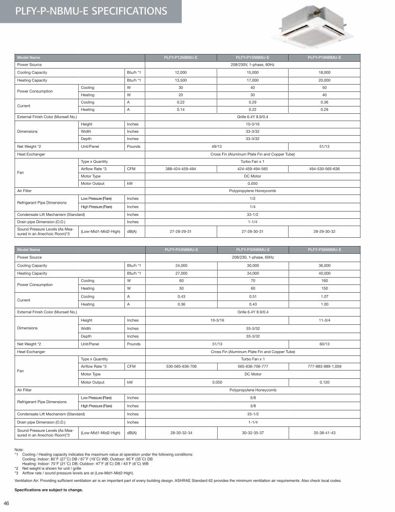
46
Model Name PLFY-P24NBMU-E PLFY-P30NBMU-E PLFY-P36NBMU-E
Power Source 208/230, 1-phase, 60Hz
Cooling Capacity Btu/h *1 24,000 30,000 36,000
Heating Capacity Btu/h *1 27,000 34,000 40,000
Power ConsumptionCooling W 60 70 160
Heating W 50 60 150
CurrentCooling A 0.43 0.51 1.07
Heating A 0.36 0.43 1.00
External Finish Color (Munsell No.) Grille 6.4Y 8.9/0.4
Dimensions
Height Inches 10-3/16 11-3/4
Width Inches 33-3/32
Depth Inches 33-3/32
Net Weight *2 Unit/Panel Pounds 51/13 60/13
Heat Exchanger Cross Fin (Aluminum Plate Fin and Copper Tube)
Fan
Type x Quantity Turbo Fan x 1
Airflow Rate *3 CFM 530-565-636-706 565-636-706-777 777-883-989-1,059
Motor Type DC Motor
Motor Output kW 0.050 0.120
Air Filter Polypropylene Honeycomb
Refrigerant Pipe DimensionsLow Pressure (Flare) Inches 5/8
High Pressure (Flare) Inches 3/8
Condensate Lift Mechanism (Standard) Inches 33-1/2
Drain pipe Dimension (O.D.) Inches 1-1/4
Sound Pressure Levels (As Mea-sured in an Anechoic Room)*3
(Low-Mid1-Mid2-High) dB(A) 28-30-32-34 30-32-35-37 35-38-41-43
Note: *1 Cooling / Heating capacity indicates the maximum value at operation under the following conditions: Cooling:Indoor:80˚F(27˚C)DB/67˚F(19˚C)WB;Outdoor:95˚F(35˚C)DB Heating:Indoor:70˚F(21˚C)DB;Outdoor:47˚F(8˚C)DB/43˚F(6˚C)WB*2 Net weight is shown for unit / grille*3 Airflowrate/soundpressurelevelsareat(Low-Mid1-Mid2-High).
VentilationAir:Providingsufficientventilationairisanimportantpartofeverybuildingdesign.ASHRAEStandard62providestheminimumventilationairrequirements.Alsochecklocalcodes.
Specifications are subject to change.
Model Name PLFY-P12NBMU-E PLFY-P15NBMU-E PLFY-P18NBMU-E
Power Source 208/230V, 1-phase, 60Hz
Cooling Capacity Btu/h *1 12,000 15,000 18,000
Heating Capacity Btu/h *1 13,500 17,000 20,000
Power ConsumptionCooling W 30 40 50
Heating W 20 30 40
CurrentCooling A 0.22 0.29 0.36
Heating A 0.14 0.22 0.29
External Finish Color (Munsell No.) Grille 6.4Y 8.9/0.4
Dimensions
Height Inches 10-3/16
Width Inches 33-3/32
Depth Inches 33-3/32
Net Weight *2 Unit/Panel Pounds 49/13 51/13
Heat Exchanger Cross Fin (Aluminum Plate Fin and Copper Tube)
Fan
Type x Quantity Turbo Fan x 1
Airflow Rate *3 CFM 388-424-459-494 424-459-494-565 494-530-565-636
Motor Type DC Motor
Motor Output kW 0.050
Air Filter Polypropylene Honeycomb
Refrigerant Pipe DimensionsLow Pressure (Flare) Inches 1/2
High Pressure (Flare) Inches 1/4
Condensate Lift Mechanism (Standard) Inches 33-1/2
Drain pipe Dimension (O.D.) Inches 1-1/4
Sound Pressure Levels (As Mea-sured in an Anechoic Room)*3
(Low-Mid1-Mid2-High) dB(A) 27-28-29-31 27-28-30-31 28-29-30-32
PLFY-P-NBMU-E SPECIFICATIONS
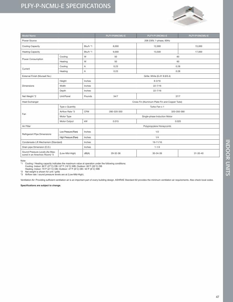
47
Model Name PLFY-P08NCMU-E PLFY-P12NCMU-E PLFY-P15NCMU-E
Power Source 208 230V, 1-phase, 60Hz
Cooling Capacity Btu/h *1 8,000 12,000 15,000
Heating Capacity Btu/h *1 9,000 13,500 17,000
Power ConsumptionCooling W 50 60
Heating W 50 60
CurrentCooling A 0.23 0.28
Heating A 0.23 0.28
External Finish (Munsell No.) Grille: White (6.4Y 8.9/0.4)
Dimensions
Height Inches 8-3/16
Width Inches 22-7/16
Depth Inches 22-7/16
Net Weight *2 Unit/Panel Pounds 34/7 37/7
Heat Exchanger Cross Fin (Aluminum Plate Fin and Copper Tube)
Fan
Type x Quantity Turbo Fan x 1
Airflow Rate *3 CFM 280-320-350 320-350-390
Motor Type Single-phase Induction Motor
Motor Output kW 0.015 0.020
Air Filter Polypropylene Honeycomb
Refrigerant Pipe DimensionsLow Pressure (Flare) Inches 1/2
High Pressure (Flare) Inches 1/4
Condensate Lift Mechanism (Standard) Inches 19-11/16
Drain pipe Dimension (O.D.) Inches 1-1/4
Sound Pressure Levels (As Mea-sured in an Anechoic Room) *3
(Low-Mid-High) dB(A) 29-32-38 30-34-39 31-35-40
Note: *1 Cooling / Heating capacity indicates the maximum value at operation under the following conditions: Cooling:Indoor:80˚F(27˚C)DB/67˚F(19˚C)WB;Outdoor:95˚F(35˚C)DB Heating:Indoor:70˚F(21˚C)DB;Outdoor:47˚F(8˚C)DB/43˚F(6˚C)WB*2 Net weight is shown for unit / grille*3 Airflowrate/soundpressurelevelsareat(Low-Mid-High).
VentilationAir:Providingsufficientventilationairisanimportantpartofeverybuildingdesign.ASHRAEStandard62providestheminimumventilationairrequirements.Alsochecklocalcodes.
Specifications are subject to change.
PLFY-P-NCMU-E SPECIFICATIONSIN
DO
OR U
NITS
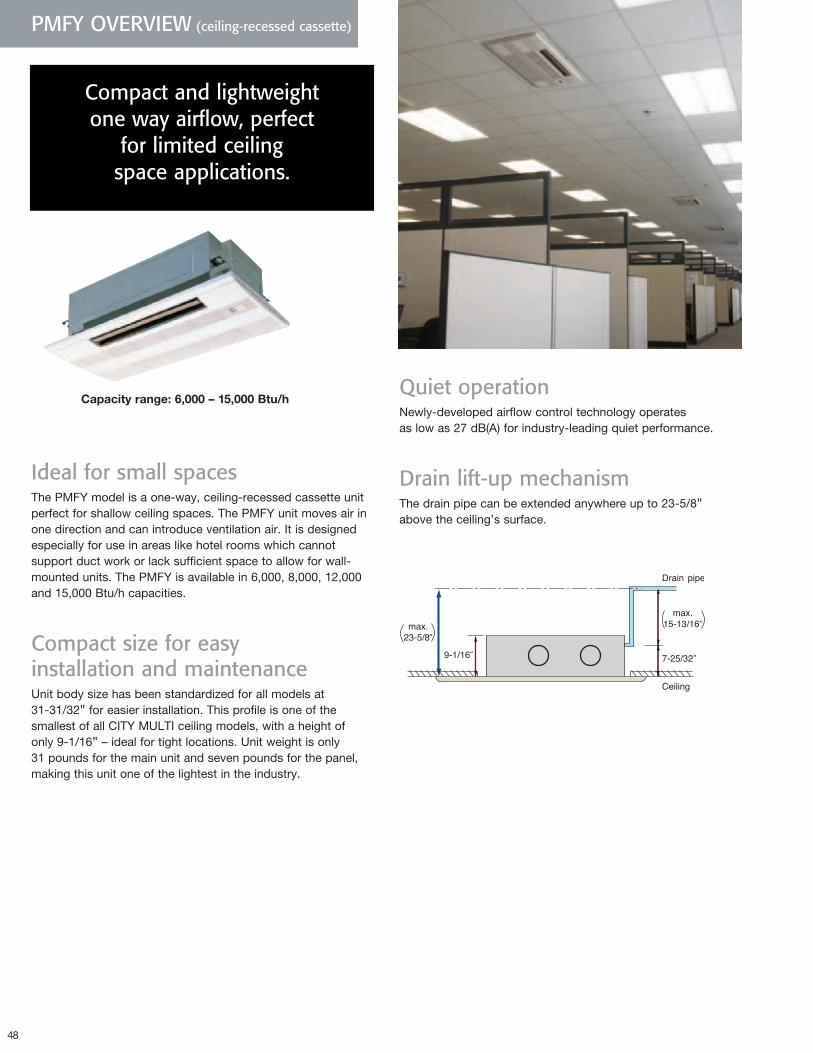
48
PMFY OVERVIEW (ceiling-recessed cassette)
Capacityrange:6,000–15,000Btu/hQuiet operation Newly-developed airflow control technology operates as low as 27 dB(A) for industry-leading quiet performance.
Drain lift-up mechanismThe drain pipe can be extended anywhere up to 23-5/8" above the ceiling’s surface.
Ideal for small spacesThe PMFY model is a one-way, ceiling-recessed cassette unit perfect for shallow ceiling spaces. The PMFY unit moves air in one direction and can introduce ventilation air. It is designed especially for use in areas like hotel rooms which cannot support duct work or lack sufficient space to allow for wall-mounted units. The PMFY is available in 6,000, 8,000, 12,000 and 15,000 Btu/h capacities.
Compact size for easy installation and maintenanceUnit body size has been standardized for all models at 31-31/32" for easier installation. This profile is one of the smallest of all CITY MULTI ceiling models, with a height of only 9-1/16" – ideal for tight locations. Unit weight is only 31 pounds for the main unit and seven pounds for the panel, making this unit one of the lightest in the industry.
Compact and lightweight one way airflow, perfect
for limited ceiling space applications.
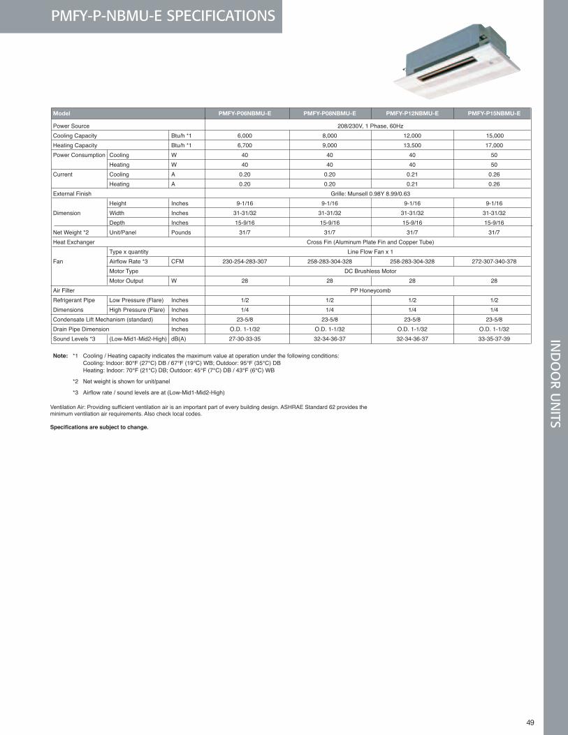
49 49
Model PMFY-P06NBMU-E PMFY-P08NBMU-E PMFY-P12NBMU-E PMFY-P15NBMU-E Power Source 208/230V, 1 Phase, 60Hz Cooling Capacity Btu/h *1 6,000 8,000 12,000 15,000 Heating Capacity Btu/h *1 6,700 9,000 13,500 17,000 Power Consumption Cooling W 40 40 40 50 Heating W 40 40 40 50 Current Cooling A 0.20 0.20 0.21 0.26 Heating A 0.20 0.20 0.21 0.26 External Finish Grille: Munsell 0.98Y 8.99/0.63 Height Inches 9-1/16 9-1/16 9-1/16 9-1/16 Dimension Width Inches 31-31/32 31-31/32 31-31/32 31-31/32 Depth Inches 15-9/16 15-9/16 15-9/16 15-9/16Net Weight *2 Unit/Panel Pounds 31/7 31/7 31/7 31/7 Heat Exchanger Cross Fin (Aluminum Plate Fin and Copper Tube) Type x quantity Line Flow Fan x 1 Fan Airflow Rate *3 CFM 230-254-283-307 258-283-304-328 258-283-304-328 272-307-340-378 Motor Type DC Brushless Motor Motor Output W 28 28 28 28 Air Filter PP Honeycomb Refrigerant Pipe Low Pressure (Flare) Inches 1/2 1/2 1/2 1/2 Dimensions High Pressure (Flare) Inches 1/4 1/4 1/4 1/4 Condensate Lift Mechanism (standard) Inches 23-5/8 23-5/8 23-5/8 23-5/8Drain Pipe Dimension Inches O.D. 1-1/32 O.D. 1-1/32 O.D. 1-1/32 O.D. 1-1/32 Sound Levels *3 (Low-Mid1-Mid2-High) dB(A) 27-30-33-35 32-34-36-37 32-34-36-37 33-35-37-39
Note: *1 Cooling / Heating capacity indicates the maximum value at operation under the following conditions: Cooling: Indoor: 80°F (27°C) DB / 67°F (19°C) WB; Outdoor: 95°F (35°C) DB Heating: Indoor: 70°F (21°C) DB; Outdoor: 45°F (7°C) DB / 43°F (6°C) WB *2 Net weight is shown for unit/panel *3 Airflow rate / sound levels are at (Low-Mid1-Mid2-High)
PMFY-P-NBMU-E SPECIFICATIONSIN
DO
OR U
NITS
VentilationAir:Providingsufficientventilationairisanimportantpartofeverybuildingdesign.ASHRAEStandard62providesthe minimum ventilation air requirements . Also check local codes .
Specifications are subject to change.
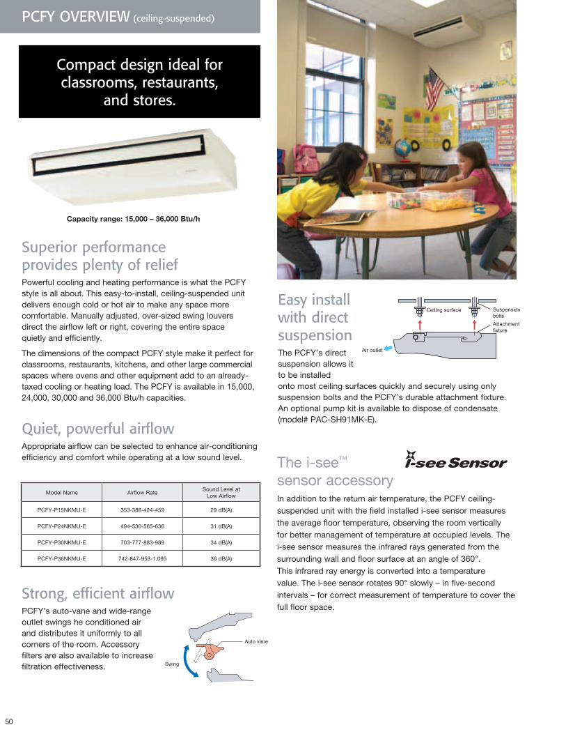
50
The i-see™ sensor accessoryIn addition to the return air temperature, the PCFY ceiling- suspended unit with the field installed i-see sensor measures the average floor temperature, observing the room vertically for better management of temperature at occupied levels. The i-see sensor measures the infrared rays generated from the surrounding wall and floor surface at an angle of 360°. This infrared ray energy is converted into a temperature value. The i-see sensor rotates 90° slowly – in five-second intervals – for correct measurement of temperature to cover the full floor space.
Capacityrange:15,000–36,000Btu/h
Easy install with direct suspensionThe PCFY’s direct suspension allows it to be installed onto most ceiling surfaces quickly and securely using only suspension bolts and the PCFY’s durable attachment fixture. An optional pump kit is available to dispose of condensate (model# PAC-SH91MK-E).
Strong, efficient airflowPCFY’s auto-vane and wide-range outlet swings he conditioned air and distributes it uniformly to all corners of the room. Accessory filters are also available to increase filtration effectiveness.
Superior performance provides plenty of reliefPowerful cooling and heating performance is what the PCFY style is all about. This easy-to-install, ceiling-suspended unit delivers enough cold or hot air to make any space more comfortable. Manually adjusted, over-sized swing louvers direct the airflow left or right, covering the entire space quietly and efficiently.
The dimensions of the compact PCFY style make it perfect for classrooms, restaurants, kitchens, and other large commercial spaces where ovens and other equipment add to an already-taxed cooling or heating load. The PCFY is available in 15,000, 24,000, 30,000 and 36,000 Btu/h capacities.
Quiet, powerful airflowAppropriate airflow can be selected to enhance air-conditioning efficiency and comfort while operating at a low sound level.
PCFY-P-NGMU-E
Ceiling-suspended type's compact dimensions ideal for restaurant, stores uses
The PCFY's auto-vane swing the conditioned air and distribute it uniformly to corners of the room.
Outlet Max. airflow Noise level at low airflow PCFY-P15NGMU-E 35-19/32 in. 424 CFM 29 dBA PCFY-P24NGMU-E 48-11/32 in. 636 CFM 32 dBA PCFY-P30NGMU-E 48-11/32 in. 883 CFM 36 dBA PCFY-P36NGMU-E 60- 7/16 in. 1236 CFM 37 dBA
PCFY-P-NGMU-E
3.2HP 8.0HP 4.0HP 5.0HP
P08 P12 P15 P18 P30 P36 P48 P06 P24 P27 P54 P72
10.0HP
P96
0.8HP 1.0HP 1.3HP 1.6HP 2.0HP 2.5HP 2.8HP 5.6HP Ceiling suspended
48,000 6,700
Nominal cooling cap.*1
Nominal heating cap.*2 6,000 8,000 12,000 15,000 18,000 24,000 27,000 30,000 36,000 54,000 72,000 96,000
60,000 80,000 108,000 27,000 30,000 34,000 40,000 54,000 9,000 13,500 17,000 20,000 BTU/h BTU/h
* Nominal conditions *1, *2 are referable at the Specification sheet.
Swing
Auto vane
Suspension bolts
Attachment fixture
Ceiling surface
Air outlet
* Nominal conditions *1, *2 are referred to in the Speci fi cation sheet.
Wide-range outlet, strong airflow provides uniform air temperature and is extremely quiet.
Strong airflow effective even at a ceiling height of 11 -5 .
The PCFY’s auto-vane swings the conditioned air and distributes it uniformly to corners of the room.
The ceiling-suspended compact dimensions are ideal for restaurants and stores.
Easy install by direct suspending.
Powerful cooling and heating performance is what the PCFY-Series is all about. This ceiling-suspended unit delivers enough cold or hot air to make any space more comfortable. Manually-adjusted over-sized swing louvers direct the airflow left or right, quietly covering the entire space. Accessory filters are available to increase efficiency and increase the time span between service calls. The PCFY-Series is perfect for restaurants, kitchens, and other larger commercial spaces where ovens and other equipment add to an already taxed cooling or heating load.
Model Name Airflow RateSound Level at
Low Airflow
PCFY-P15NKMU-E 353-388-424-459 29 dB(A)
PCFY-P24NKMU-E 494-530-565-636 31 dB(A)
PCFY-P30NKMU-E 703-777-883-989 34 dB(A)
PCFY-P36NKMU-E 742-847-953-1,095 36 dB(A)
Compact design ideal for classrooms, restaurants,
and stores.
PCFY OVERVIEW (ceiling-suspended)
PCFY-P-NGMU-E
Ceiling-suspended type's compact dimensions ideal for restaurant, stores uses
The PCFY's auto-vane swing the conditioned air and distribute it uniformly to corners of the room.
Outlet Max. airflow Noise level at low airflow PCFY-P15NGMU-E 35-19/32 in. 424 CFM 29 dBA PCFY-P24NGMU-E 48-11/32 in. 636 CFM 32 dBA PCFY-P30NGMU-E 48-11/32 in. 883 CFM 36 dBA PCFY-P36NGMU-E 60- 7/16 in. 1236 CFM 37 dBA
PCFY-P-NGMU-E
3.2HP 8.0HP 4.0HP 5.0HP
P08 P12 P15 P18 P30 P36 P48 P06 P24 P27 P54 P72
10.0HP
P96
0.8HP 1.0HP 1.3HP 1.6HP 2.0HP 2.5HP 2.8HP 5.6HP Ceiling suspended
48,000 6,700
Nominal cooling cap.*1
Nominal heating cap.*2 6,000 8,000 12,000 15,000 18,000 24,000 27,000 30,000 36,000 54,000 72,000 96,000
60,000 80,000 108,000 27,000 30,000 34,000 40,000 54,000 9,000 13,500 17,000 20,000 BTU/h BTU/h
* Nominal conditions *1, *2 are referable at the Specification sheet.
Swing
Auto vane
Suspension bolts
Attachment fixture
Ceiling surface
Air outlet
* Nominal conditions *1, *2 are referred to in the Speci fi cation sheet.
Wide-range outlet, strong airflow provides uniform air temperature and is extremely quiet.
Strong airflow effective even at a ceiling height of 11 -5 .
The PCFY’s auto-vane swings the conditioned air and distributes it uniformly to corners of the room.
The ceiling-suspended compact dimensions are ideal for restaurants and stores.
Easy install by direct suspending.
Powerful cooling and heating performance is what the PCFY-Series is all about. This ceiling-suspended unit delivers enough cold or hot air to make any space more comfortable. Manually-adjusted over-sized swing louvers direct the airflow left or right, quietly covering the entire space. Accessory filters are available to increase efficiency and increase the time span between service calls. The PCFY-Series is perfect for restaurants, kitchens, and other larger commercial spaces where ovens and other equipment add to an already taxed cooling or heating load.
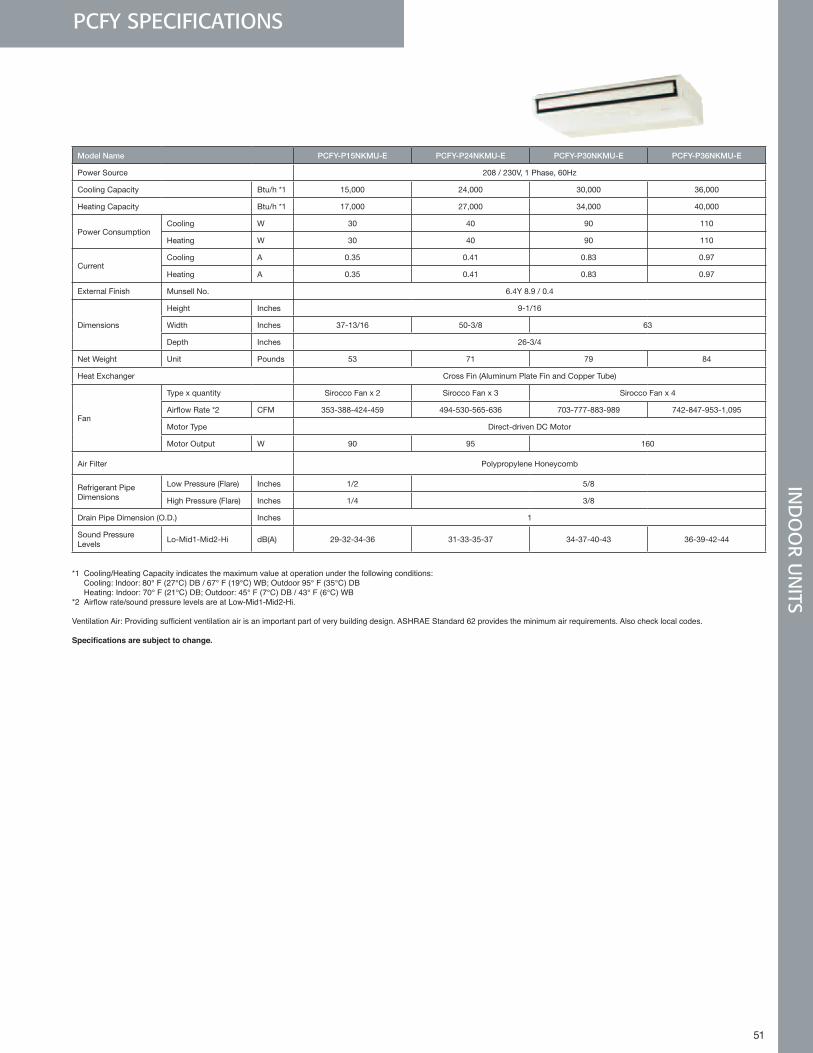
51 51
PCFY SPECIFICATIONSIN
DO
OR U
NITS
Model Name PCFY-P15NKMU-E PCFY-P24NKMU-E PCFY-P30NKMU-E PCFY-P36NKMU-E
Power Source 208 / 230V, 1 Phase, 60Hz
Cooling Capacity Btu/h *1 15,000 24,000 30,000 36,000
Heating Capacity Btu/h *1 17,000 27,000 34,000 40,000
Power ConsumptionCooling W 30 40 90 110
Heating W 30 40 90 110
CurrentCooling A 0.35 0.41 0.83 0.97
Heating A 0.35 0.41 0.83 0.97
External Finish Munsell No. 6.4Y 8.9 / 0.4
Dimensions
Height Inches 9-1/16
Width Inches 37-13/16 50-3/8 63
Depth Inches 26-3/4
Net Weight Unit Pounds 53 71 79 84
Heat Exchanger Cross Fin (Aluminum Plate Fin and Copper Tube)
Fan
Type x quantity Sirocco Fan x 2 Sirocco Fan x 3 Sirocco Fan x 4
Airflow Rate *2 CFM 353-388-424-459 494-530-565-636 703-777-883-989 742-847-953-1,095
Motor Type Direct-driven DC Motor
Motor Output W 90 95 160
Air Filter Polypropylene Honeycomb
Refrigerant Pipe Dimensions
Low Pressure (Flare) Inches 1/2 5/8
High Pressure (Flare) Inches 1/4 3/8
Drain Pipe Dimension (O.D.) Inches 1
Sound Pressure Levels
Lo-Mid1-Mid2-Hi dB(A) 29-32-34-36 31-33-35-37 34-37-40-43 36-39-42-44
*1 Cooling/Heating Capacity indicates the maximum value at operation under the following conditions: Cooling: Indoor: 80° F (27°C) DB / 67° F (19°C) WB; Outdoor 95° F (35°C) DB Heating: Indoor: 70° F (21°C) DB; Outdoor: 45° F (7°C) DB / 43° F (6°C) WB*2Airflowrate/soundpressurelevelsareatLow-Mid1-Mid2-Hi.
VentilationAir:Providingsufficientventilationairisanimportantpartofverybuildingdesign.ASHRAEStandard62providestheminimumairrequirements.Alsochecklocalcodes.
Specifications are subject to change.
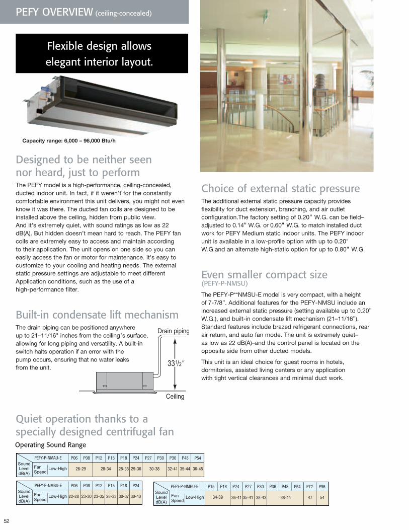
52
PEFY OVERVIEW (ceiling-concealed)
Quiet operation thanks to a specially designed centrifugal fan
PEFY-P-NMAU-E
PEFY-P-NMSU-E
22-28 23-30 23-35 28-33 30-37 30-40
PEFY-P-NMHU-E P54 P72 P96
36-41 35-41 38-43 38-44 47 54
P54
36-4526-29 28-34 28-35 29-36 30-38 32-41 35-44
PEFY-P-NMAU-E
PEFY-P-NMSU-E
22-28 23-30 23-35 28-33 30-37 30-40
PEFY-P-NMHU-E P54 P72 P96
36-41 35-41 38-43 38-44 47 54
P54
36-4526-29 28-34 28-35 29-36 30-38 32-41 35-44
Flexible design allows elegant interior layout.
Designed to be neither seen nor heard, just to performThe PEFY model is a high-performance, ceiling-concealed, ducted indoor unit. In fact, if it weren’t for the constantly comfortable environment this unit delivers, you might not even know it was there. The ducted fan coils are designed to be installed above the ceiling, hidden from public view. And it's extremely quiet, with sound ratings as low as 22 dB(A). But hidden doesn’t mean hard to reach. The PEFY fan coils are extremely easy to access and maintain according to their application. The unit opens on one side so you can easily access the fan or motor for maintenance. It's easy to customize to your cooling and heating needs. The external static pressure settings are adjustable to meet different Application conditions, such as the use of a high-performance filter.
Built-in condensate lift mechanism The drain piping can be positioned anywhere up to 21–11/16" inches from the ceiling’s surface, allowing for long piping and versatility. A built-in switch halts operation if an error with the pump occurs, ensuring that no water leaks from the unit.
Operating Sound Range
Choice of external static pressureThe additional external static pressure capacity provides flexibility for duct extension, branching, and air outlet configuration.The factory setting of 0.20" W.G. can be field–adjusted to 0.14" W.G. or 0.60" W.G. to match installed duct work for PEFY Medium static indoor units. The PEFY indoor unit is available in a low-profile option with up to 0.20" W.G.and an alternate high-static option for up to 0.80" W.G.
Even smaller compact size (PEFY-P-NMSU)
The PEFY-P**NMSU-E model is very compact, with a height of 7-7/8". Additional features for the PEFY-NMSU include an increased external static pressure (setting available up to 0.20" W.G.), and built-in condensate lift mechanism (21–11/16"). Standard features include brazed refrigerant connections, rear air return, and auto fan mode. The unit is extremely quiet–as low as 22 dB(A)–and the control panel is located on the opposite side from other ducted models.
This unit is an ideal choice for guest rooms in hotels, dormitories, assisted living centers or any application with tight vertical clearances and minimal duct work.
Capacityrange:6,000–96,000Btu/h
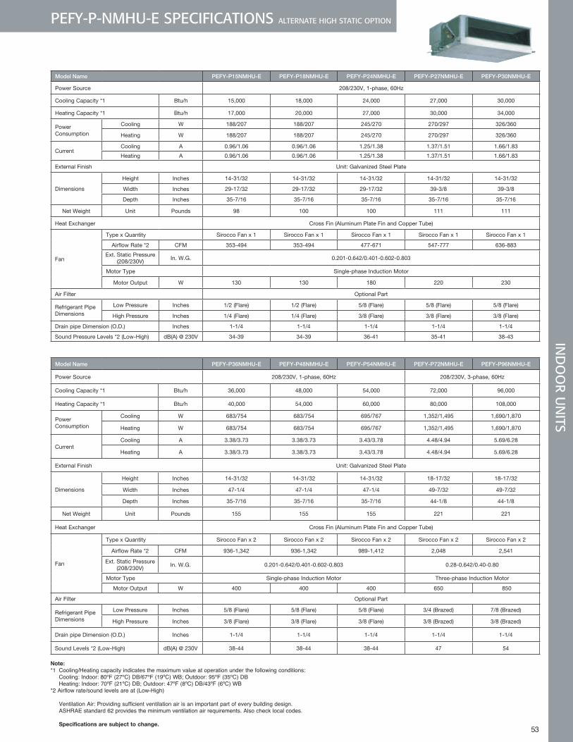
53
PEFY-P-NMHU-E SPECIFICATIONS ALTERNATE HIGH STATIC OPTION
Model Name PEFY-P15NMHU-E PEFY-P18NMHU-E PEFY-P24NMHU-E PEFY-P27NMHU-E PEFY-P30NMHU-E
Power Source 208/230V, 1-phase, 60Hz
Cooling Capacity *1 Btu/h 15,000 18,000 24,000 27,000 30,000
Heating Capacity *1 Btu/h 17,000 20,000 27,000 30,000 34,000
Power Consumption
Cooling W 188/207 188/207 245/270 270/297 326/360
Heating W 188/207 188/207 245/270 270/297 326/360
CurrentCooling A 0.96/1.06 0.96/1.06 1.25/1.38 1.37/1.51 1.66/1.83
Heating A 0.96/1.06 0.96/1.06 1.25/1.38 1.37/1.51 1.66/1.83
External Finish Unit: Galvanized Steel Plate
Dimensions
Height Inches 14-31/32 14-31/32 14-31/32 14-31/32 14-31/32
Width Inches 29-17/32 29-17/32 29-17/32 39-3/8 39-3/8
Depth Inches 35-7/16 35-7/16 35-7/16 35-7/16 35-7/16
Net Weight Unit Pounds 98 100 100 111 111
Heat Exchanger Cross Fin (Aluminum Plate Fin and Copper Tube)
Fan
Type x Quantity Sirocco Fan x 1 Sirocco Fan x 1 Sirocco Fan x 1 Sirocco Fan x 1 Sirocco Fan x 1
Airflow Rate *2 CFM 353-494 353-494 477-671 547-777 636-883
Ext. Static Pressure (208/230V)
In. W.G. 0.201-0.642/0.401-0.602-0.803
Motor Type Single-phase Induction Motor
Motor Output W 130 130 180 220 230
Air Filter Optional Part
Refrigerant Pipe Dimensions
Low Pressure Inches 1/2 (Flare) 1/2 (Flare) 5/8 (Flare) 5/8 (Flare) 5/8 (Flare)
High Pressure Inches 1/4 (Flare) 1/4 (Flare) 3/8 (Flare) 3/8 (Flare) 3/8 (Flare)
Drain pipe Dimension (O.D.) Inches 1-1/4 1-1/4 1-1/4 1-1/4 1-1/4
Sound Pressure Levels *2 (Low-High) dB(A) @ 230V 34-39 34-39 36-41 35-41 38-43
Model Name PEFY-P36NMHU-E PEFY-P48NMHU-E PEFY-P54NMHU-E PEFY-P72NMHU-E PEFY-P96NMHU-E
Power Source 208/230V, 1-phase, 60Hz 208/230V, 3-phase, 60Hz
Cooling Capacity *1 Btu/h 36,000 48,000 54,000 72,000 96,000
Heating Capacity *1 Btu/h 40,000 54,000 60,000 80,000 108,000
Power Consumption
Cooling W 683/754 683/754 695/767 1,352/1,495 1,690/1,870
Heating W 683/754 683/754 695/767 1,352/1,495 1,690/1,870
CurrentCooling A 3.38/3.73 3.38/3.73 3.43/3.78 4.48/4.94 5.69/6.28
Heating A 3.38/3.73 3.38/3.73 3.43/3.78 4.48/4.94 5.69/6.28
External Finish Unit: Galvanized Steel Plate
Dimensions
Height Inches 14-31/32 14-31/32 14-31/32 18-17/32 18-17/32
Width Inches 47-1/4 47-1/4 47-1/4 49-7/32 49-7/32
Depth Inches 35-7/16 35-7/16 35-7/16 44-1/8 44-1/8
Net Weight Unit Pounds 155 155 155 221 221
Heat Exchanger Cross Fin (Aluminum Plate Fin and Copper Tube)
Fan
Type x Quantity Sirocco Fan x 2 Sirocco Fan x 2 Sirocco Fan x 2 Sirocco Fan x 2 Sirocco Fan x 2
Airflow Rate *2 CFM 936-1,342 936-1,342 989-1,412 2,048 2,541
Ext. Static Pressure (208/230V)
In. W.G. 0.201-0.642/0.401-0.602-0.803 0.28-0.642/0.40-0.80
Motor Type Single-phase Induction Motor Three-phase Induction Motor
Motor Output W 400 400 400 650 850
Air Filter Optional Part
Refrigerant Pipe Dimensions
Low Pressure Inches 5/8 (Flare) 5/8 (Flare) 5/8 (Flare) 3/4 (Brazed) 7/8 (Brazed)
High Pressure Inches 3/8 (Flare) 3/8 (Flare) 3/8 (Flare) 3/8 (Brazed) 3/8 (Brazed)
Drain pipe Dimension (O.D.) Inches 1-1/4 1-1/4 1-1/4 1-1/4 1-1/4
Sound Levels *2 (Low-High) dB(A) @ 230V 38-44 38-44 38-44 47 54
Note: *1 Cooling/Heating capacity indicates the maximum value at operation under the following conditions: Cooling: Indoor: 80ºF (27ºC) DB/67ºF (19ºC) WB; Outdoor: 95ºF (35ºC) DB Heating: Indoor: 70ºF (21ºC) DB; Outdoor: 47ºF (8ºC) DB/43ºF (6ºC) WB *2 Airflow rate/sound levels are at (Low-High)
Ventilation Air: Providing sufficient ventilation air is an important part of every building design . ASHRAE standard 62 provides the minimum ventilation air requirements . Also check local codes . Specificationsaresubjecttochange.
IND
OO
R UN
ITS
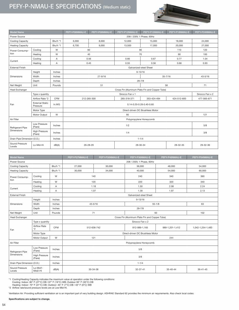
54
PEFY-P-NMAU-E SPECIFICATIONS (Medium static)
Model Name PEFY-P06NMAU-E PEFY-P08NMAU-E PEFY-P12NMAU-E PEFY-P15NMAU-E PEFY-P18NMAU-E PEFY-P24NMAU-E
Power Source 208 / 230V, 1 Phase, 60Hz
Cooling Capacity Btu/h *1 6,000 8,000 12,000 15,000 18,000 24,000
Heating Capacity Btu/h *1 6,700 9,000 13,500 17,000 20,000 27,000
Power Consump-tion
Cooling W 60 90 110 120
Heating W 40 70 90 100
CurrentCooling A 0.56 0.66 0.67 0.77 1.04
Heating A 0.45 0.55 0.56 0.66 0.93
External Finish Galvanized-steel Sheet
Dimensions
Height Inches 9-13/16
Width Inches 27-9/16 35-7/16 43-5/16
Depth Inches 28-7/8
Net Weight Unit Pounds 51 58 71
Heat Exchanger Cross Fin (Aluminum Plate Fin and Copper Tube)
Fan
Type x quantity Sirocco Fan x 1 Sirocco Fan x 2
Airflow Rate *2 CFM 212-265-300 265-318-371 353-424-494 424-512-600 477-565-671
External Static Pressure
In.WG 0.14-0.20-0.28-0.40-0.60
Motor Type Direct-driven DC Brushless Motor
Motor Output W 85 121
Air Filter Polypropylene Honeycomb
Refrigerant Pipe Dimensions
Low Pressure (Flare)
Inches 1/2 5/8
High Pressure (Flare)
Inches 1/4 3/8
Drain Pipe Dimension (O.D.) Inches 1-1/4
Sound Pressure Levels
Lo-Mid-Hi dB(A) 26-28-29 28-30-34 28-32-35 29-32-36
Model Name PEFY-P27NMAU-E PEFY-P30NMAU-E PEFY-P36NMAU-E PEFY-P48NMAU-E PEFY-P54NMAU-E
Power Source 208 / 230V, 1 Phase, 60Hz
Cooling Capacity Btu/h *1 27,000 30,000 36,000 48,000 54,000
Heating Capacity Btu/h *1 30,000 34,000 40,000 54,000 60,000
Power Consump-tion
Cooling W 140 240 340 360
Heating W 120 220 320 340
CurrentCooling A 1.18 1.50 2.08 2.24
Heating A 1.07 1.39 1.97 2.13
External Finish Galvanized-steel Sheet
Dimensions
Height Inches 9-13/16
Width Inches 43-5/16 55-1/8 63
Depth Inches 28-7/8
Net Weight Unit Pounds 71 93 102
Heat Exchanger Cross Fin (Aluminum Plate Fin and Copper Tube)
Fan
Type x quantity Sirocco Fan x 2
Airflow Rate *2
CFM 512-636-742 812-989-1,165 989-1,201-1,412 1,042-1,254-1,483
Motor Type Direct-driven DC Brushless Motor
Motor Output W 121 244
Air Filter Polypropylene Honeycomb
Refrigerant Pipe Dimensions
Low Pressure (Flare)
Inches 5/8
High Pressure (Flare)
Inches 3/8
Drain Pipe Dimension (O.D.) Inches 1-1/4
Sound Pressure Levels
Lo-Mid1-Mid2-Hi
dB(A) 30-34-38 32-37-41 35-40-44 36-41-45
*1 Cooling/Heating Capacity indicates the maximum value at operation under the following conditions: Cooling: Indoor: 80° F (27°C) DB / 67° F (19°C) WB; Outdoor 95° F (35°C) DB Heating: Indoor: 70° F (21°C) DB; Outdoor: 45° F (7°C) DB / 43° F (6°C) WB*2Airflowrate/soundpressurelevelsareatLow-Mid-Hi.
VentilationAir:Providingsufficientventilationairisanimportantpartofverybuildingdesign.ASHRAEStandard62providestheminimumairrequirements.Alsochecklocalcodes.
Specifications are subject to change.
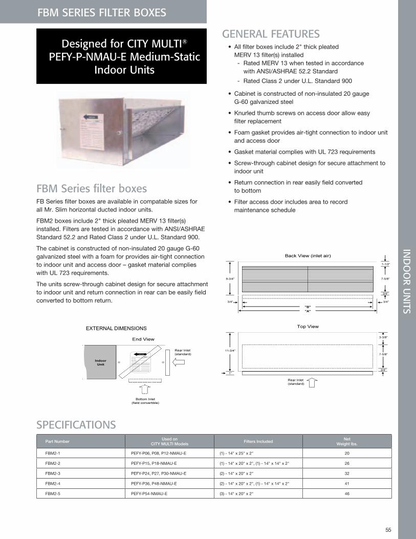
55
IND
OO
R UN
ITSFBM SERIES FILTER BOXES
FBM Series filter boxesFB Series filter boxes are available in compatable sizes for all Mr. Slim horizontal ducted indoor units.
FBM2 boxes include 2" thick pleated MERV 13 filter(s) installed. Filters are tested in accordance with ANSI/ASHRAE Standard 52.2 and Rated Class 2 under U.L. Standard 900.
The cabinet is constructed of non-insulated 20 gauge G-60 galvanized steel with a foam for provides air-tight connection to indoor unit and access door – gasket material complies with UL 723 requirements.
The units screw-through cabinet design for secure attachment to indoor unit and return connection in rear can be easily field converted to bottom return.
GENERAL FEATURES • All filter boxes include 2" thick pleated
MERV 13 filter(s) installed - Rated MERV 13 when tested in accordance
with ANSI/ASHRAE 52.2 Standard
- Rated Class 2 under U.L. Standard 900
• Cabinet is constructed of non-insulated 20 gauge G-60 galvanized steel
• Knurled thumb screws on access door allow easy filter replacement
• Foam gasket provides air-tight connection to indoor unit and access door
• Gasket material complies with UL 723 requirements
• Screw-through cabinet design for secure attachment to indoor unit
• Return connection in rear easily field converted to bottom
• Filter access door includes area to record maintenance schedule
Designed for CITY MULTI® PEFY-P-NMAU-E Medium-Static
Indoor Units
SPECIFICATIONSPart Number
Used onCITY MULTI Models
Filters IncludedNet
Weight lbs.
FBM2-1 PEFY-P06, P08, P12-NMAU-E (1) - 14" x 25" x 2" 20
FBM2-2 PEFY-P15, P18-NMAU-E (1) - 14" x 20" x 2", (1) - 14" x 14" x 2" 26
FBM2-3 PEFY-P24, P27, P30-NMAU-E (2) - 14" x 20" x 2" 32
FBM2-4 PEFY-P36, P48-NMAU-E (2) - 14" x 20" x 2", (1) - 14" x 14" x 2" 41
FBM2-5 PEFY-P54-NMAU-E (3) - 14" x 20" x 2" 46
FBM Series Filter Boxes Designed for CITY MULTI¨ PEFY-P-NMAU-E Medium-Static Indoor Units
Job Name:
Drawing Reference Schedule No.
GENERAL FEATURES● All filter boxes include 2" thick pleated MERV 13 filter(s) installed Rated MERV 13 when tested in accordance with ANSI/ASHRAE 52.2 Standard Rated Class 2 under U.L. Standard 900● Cabinet is constructed of non-insulated 20 gauge G-60 galvanized steel● Knurled thumb screws on access door allow easy filter replacement● Foam gasket provides air-tight connection to indoor unit and access door● Gasket material complies with UL 723 requirements● Screw-through cabinet design for secure attachment to indoor unit● Return connection in rear easily field converted to bottom● Filter access door includes area to record maintenance schedule
SPECIFICATIONSUsed on Ship Net
CITY MULTI Models Weight lbs. Weight lbs.FBM2-1 PEFY-P06, P08, P12-NMAU-E (1) - 14" x 25" x 2" 22 20
FBM2-2 PEFY-P15, P18-NMAU-E (1) - 14" x 20" x 2", (1) - 14" x 14" x 2" 28 26
FBM2-3 PEFY-P24, P27, P30-NMAU-E (2) - 14" x 20" x 2" 35 32
FBM2-4 PEFY-P36, P48-NMAU-E (2) - 14" x 20" x 2", (1) - 14" x 14" x 2" 44 41
FBM2-5 PEFY-P54-NMAU-E (3) - 14" x 20" x 2" 50 46
EXTERNAL DIMENSIONS
November 2009
Part Number Filters Included
Manufactured for Mitsubishi Electric and Electronics USA
Meets LEED requirement of
MERV 13
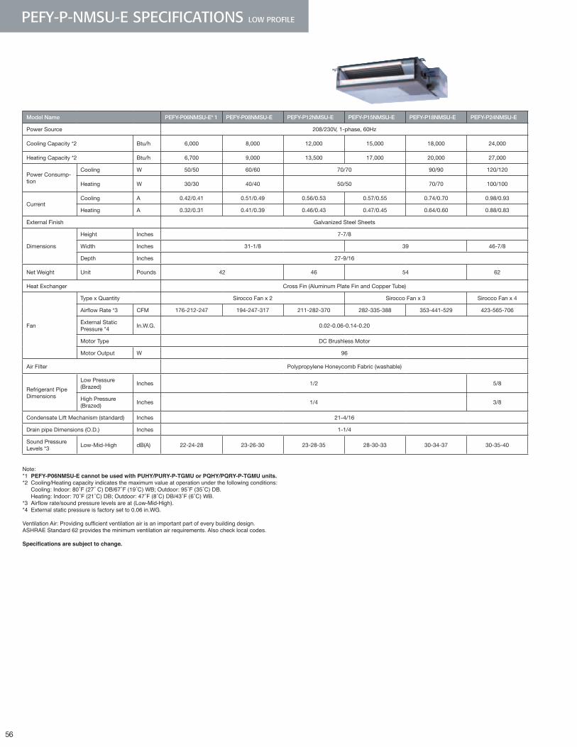
56
PEFY-P-NMSU-E SPECIFICATIONS LOW PROFILE
Model Name PEFY-P06NMSU-E* 1 PEFY-P08NMSU-E PEFY-P12NMSU-E PEFY-P15NMSU-E PEFY-P18NMSU-E PEFY-P24NMSU-E
Power Source 208/230V, 1-phase, 60Hz
Cooling Capacity *2 Btu/h 6,000 8,000 12,000 15,000 18,000 24,000
Heating Capacity *2 Btu/h 6,700 9,000 13,500 17,000 20,000 27,000
Power Consump-tion
Cooling W 50/50 60/60 70/70 90/90 120/120
Heating W 30/30 40/40 50/50 70/70 100/100
CurrentCooling A 0.42/0.41 0.51/0.49 0.56/0.53 0.57/0.55 0.74/0.70 0.98/0.93
Heating A 0.32/0.31 0.41/0.39 0.46/0.43 0.47/0.45 0.64/0.60 0.88/0.83
External Finish Galvanized Steel Sheets
Dimensions
Height Inches 7-7/8
Width Inches 31-1/8 39 46-7/8
Depth Inches 27-9/16
Net Weight Unit Pounds 42 46 54 62
Heat Exchanger Cross Fin (Aluminum Plate Fin and Copper Tube)
Fan
Type x Quantity Sirocco Fan x 2 Sirocco Fan x 3 Sirocco Fan x 4
Airflow Rate *3 CFM 176-212-247 194-247-317 211-282-370 282-335-388 353-441-529 423-565-706
External Static Pressure *4
In.W.G. 0.02-0.06-0.14-0.20
Motor Type DC Brushless Motor
Motor Output W 96
Air Filter Polypropylene Honeycomb Fabric (washable)
Refrigerant Pipe Dimensions
Low Pressure (Brazed)
Inches 1/2 5/8
High Pressure (Brazed)
Inches 1/4 3/8
Condensate Lift Mechanism (standard) Inches 21-4/16
Drain pipe Dimensions (O.D.) Inches 1-1/4
Sound Pressure Levels *3
Low-Mid-High dB(A) 22-24-28 23-26-30 23-28-35 28-30-33 30-34-37 30-35-40
Note: *1 PEFY-P06NMSU-E cannot be used with PUHY/PURY-P-TGMU or PQHY/PQRY-P-TGMU units.*2 Cooling/Heating capacity indicates the maximum value at operation under the following conditions: Cooling:Indoor:80˚F(27˚C)DB/67˚F(19˚C)WB;Outdoor:95˚F(35˚C)DB. Heating:Indoor:70˚F(21˚C)DB;Outdoor:47˚F(8˚C)DB/43˚F(6˚C)WB.*3Airflowrate/soundpressurelevelsareat(Low-Mid-High).*4 External static pressure is factory set to 0 .06 in .WG .
VentilationAir:Providingsufficientventilationairisanimportantpartofeverybuildingdesign.ASHRAE Standard 62 provides the minimum ventilation air requirements . Also check local codes .
Specifications are subject to change.
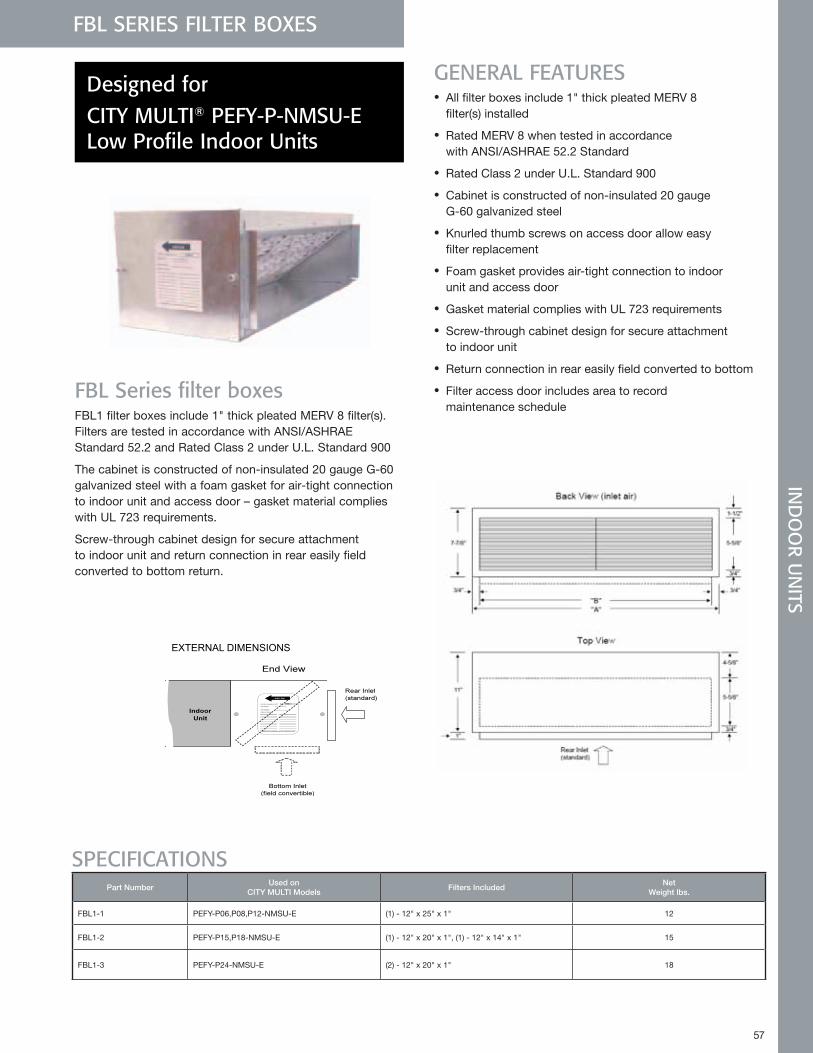
57
FBL SERIES FILTER BOXES
FBL Series filter boxesFBL1 filter boxes include 1" thick pleated MERV 8 filter(s). Filters are tested in accordance with ANSI/ASHRAE Standard 52.2 and Rated Class 2 under U.L. Standard 900
The cabinet is constructed of non-insulated 20 gauge G-60 galvanized steel with a foam gasket for air-tight connection to indoor unit and access door – gasket material complies with UL 723 requirements.
Screw-through cabinet design for secure attachment to indoor unit and return connection in rear easily field converted to bottom return.
GENERAL FEATURES • All filter boxes include 1" thick pleated MERV 8
filter(s) installed
• Rated MERV 8 when tested in accordance with ANSI/ASHRAE 52.2 Standard
• Rated Class 2 under U.L. Standard 900
• Cabinet is constructed of non-insulated 20 gauge G-60 galvanized steel
• Knurled thumb screws on access door allow easy filter replacement
• Foam gasket provides air-tight connection to indoor unit and access door
• Gasket material complies with UL 723 requirements
• Screw-through cabinet design for secure attachment to indoor unit
• Return connection in rear easily field converted to bottom
• Filter access door includes area to record maintenance schedule
Designed for CITY MULTI® PEFY-P-NMSU-E Low Profile Indoor Units
SPECIFICATIONSPart Number
Used onCITY MULTI Models
Filters IncludedNet
Weight lbs.
FBL1-1 PEFY-P06,P08,P12-NMSU-E (1) - 12" x 25" x 1" 12
FBL1-2 PEFY-P15,P18-NMSU-E (1) - 12" x 20" x 1", (1) - 12" x 14" x 1" 15
FBL1-3 PEFY-P24-NMSU-E (2) - 12" x 20" x 1" 18
FBM Series Filter Boxes Designed for CITY MULTI¨ PEFY-P-NMAU-E Medium-Static Indoor Units
Job Name:
Drawing Reference Schedule No.
GENERAL FEATURES● All filter boxes include 2" thick pleated MERV 13 filter(s) installed Rated MERV 13 when tested in accordance with ANSI/ASHRAE 52.2 Standard Rated Class 2 under U.L. Standard 900● Cabinet is constructed of non-insulated 20 gauge G-60 galvanized steel● Knurled thumb screws on access door allow easy filter replacement● Foam gasket provides air-tight connection to indoor unit and access door● Gasket material complies with UL 723 requirements● Screw-through cabinet design for secure attachment to indoor unit● Return connection in rear easily field converted to bottom● Filter access door includes area to record maintenance schedule
SPECIFICATIONSUsed on Ship Net
CITY MULTI Models Weight lbs. Weight lbs.FBM2-1 PEFY-P06, P08, P12-NMAU-E (1) - 14" x 25" x 2" 22 20
FBM2-2 PEFY-P15, P18-NMAU-E (1) - 14" x 20" x 2", (1) - 14" x 14" x 2" 28 26
FBM2-3 PEFY-P24, P27, P30-NMAU-E (2) - 14" x 20" x 2" 35 32
FBM2-4 PEFY-P36, P48-NMAU-E (2) - 14" x 20" x 2", (1) - 14" x 14" x 2" 44 41
FBM2-5 PEFY-P54-NMAU-E (3) - 14" x 20" x 2" 50 46
EXTERNAL DIMENSIONS
November 2009
Part Number Filters Included
Manufactured for Mitsubishi Electric and Electronics USA
Meets LEED requirement of
MERV 13
IND
OO
R UN
ITSIN
DO
OR U
NITS
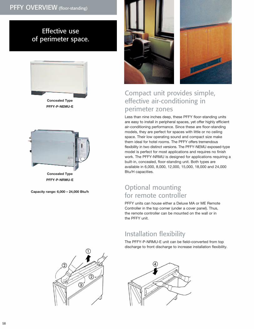
58
PFFY OVERVIEW (floor-standing)
Effective useof perimeter space.
ConcealedType
PFFY-P-NRMU-E
ConcealedType
PFFY-P-NEMU-E
Compact unit provides simple, effective air-conditioning in perimeter zonesLess than nine inches deep, these PFFY floor-standing units are easy to install in peripheral spaces, yet offer highly efficient air-conditioning performance. Since these are floor-standing models, they are perfect for spaces with little or no ceiling space. Their low operating sound and compact size make them ideal for hotel rooms. The PFFY offers tremendous flexibility in two distinct versions. The PFFY-NEMU exposed-type model is perfect for most applications and requires no finish work. The PFFY-NRMU is designed for applications requiring a built-in, concealed, floor-standing unit. Both types are available in 6,000, 8,000, 12,000, 15,000, 18,000 and 24,000 Btu/H capacities.
Optional mounting for remote controllerPFFY units can house either a Deluxe MA or ME Remote Controller in the top corner (under a cover panel). Thus, the remote controller can be mounted on the wall or in the PFFY unit.
Installation flexibilityThe PFFY-P-NRMU-E unit can be field–converted from top discharge to front discharge to increase installation flexibility.
Capacityrange:6,000–24,000Btu/h
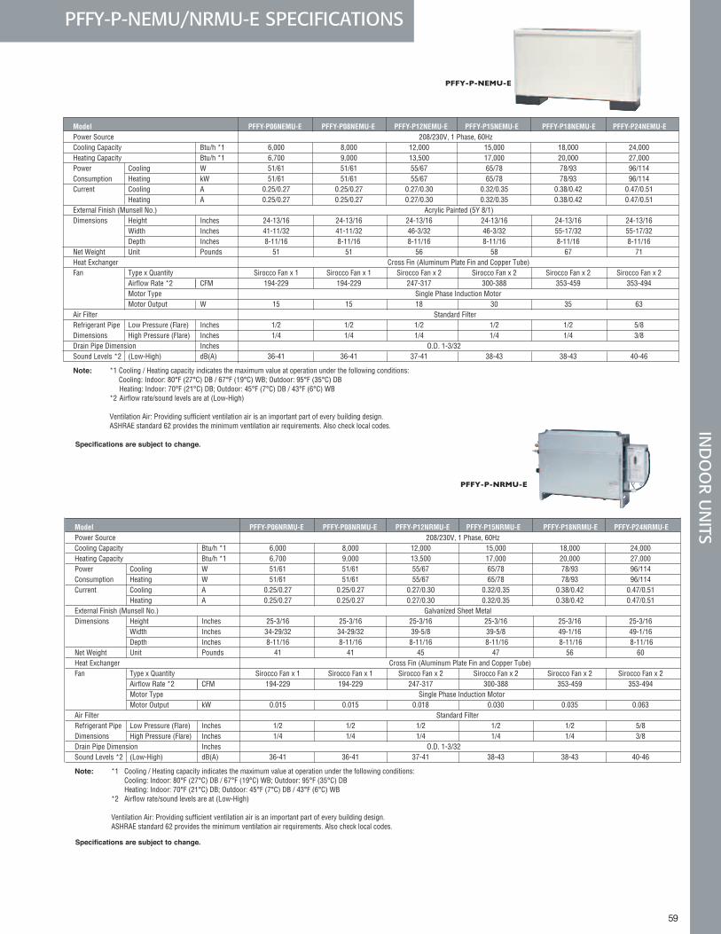
59
IND
OO
R UN
ITS
Model PFFY-P06NEMU-E PFFY-P08NEMU-E PFFY-P12NEMU-E PFFY-P15NEMU-E PFFY-P18NEMU-E PFFY-P24NEMU-E Power Source 208/230V, 1 Phase, 60Hz Cooling Capacity Btu/h *1 6,000 8,000 12,000 15,000 18,000 24,000 Heating Capacity Btu/h *1 6,700 9,000 13,500 17,000 20,000 27,000 Power Cooling W 51/61 51/61 55/67 65/78 78/93 96/114 Consumption Heating kW 51/61 51/61 55/67 65/78 78/93 96/114 Current Cooling A 0.25/0.27 0.25/0.27 0.27/0.30 0.32/0.35 0.38/0.42 0.47/0.51 Heating A 0.25/0.27 0.25/0.27 0.27/0.30 0.32/0.35 0.38/0.42 0.47/0.51 External Finish (Munsell No.) Acrylic Painted (5Y 8/1) Dimensions Height Inches 24-13/16 24-13/16 24-13/16 24-13/16 24-13/16 24-13/16 Width Inches 41-11/32 41-11/32 46-3/32 46-3/32 55-17/32 55-17/32 Depth Inches 8-11/16 8-11/16 8-11/16 8-11/16 8-11/16 8-11/16 Net Weight Unit Pounds 51 51 56 58 67 71 Heat Exchanger Cross Fin (Aluminum Plate Fin and Copper Tube) Fan Type x Quantity Sirocco Fan x 1 Sirocco Fan x 1 Sirocco Fan x 2 Sirocco Fan x 2 Sirocco Fan x 2 Sirocco Fan x 2 Airflow Rate *2 CFM 194-229 194-229 247-317 300-388 353-459 353-494 Motor Type Single Phase Induction Motor Motor Output W 15 15 18 30 35 63 Air Filter Standard Filter Refrigerant Pipe Low Pressure (Flare) Inches 1/2 1/2 1/2 1/2 1/2 5/8 Dimensions High Pressure (Flare) Inches 1/4 1/4 1/4 1/4 1/4 3/8 Drain Pipe Dimension Inches O.D. 1-3/32 Sound Levels *2 (Low-High) dB(A) 36-41 36-41 37-41 38-43 38-43 40-46
Note: *1 Cooling / Heating capacity indicates the maximum value at operation under the following conditions: Cooling: Indoor: 80°F (27°C) DB / 67°F (19°C) WB; Outdoor: 95°F (35°C) DB Heating: Indoor: 70°F (21°C) DB; Outdoor: 45°F (7°C) DB / 43°F (6°C) WB *2 Airflow rate/sound levels are at (Low-High)
Ventilation Air: Providing sufficient ventilation air is an important part of every building design. ASHRAE standard 62 provides the minimum ventilation air requirements. Also check local codes.
Model PFFY-P08NEMU-E PFFY-P12NEMU-E PFFY-P15NEMU-E PFFY-P18NEMU-E PFFY-P24NEMU-E Power Source 208/230V, 1 Phase, 60Hz Cooling Capcity Btu/h *1 8,000 12,000 15,000 18,000 24,000 Heating Capacity Btu/h *1 9,000 13,500 17,000 20,000 27,000 Power Consumption Cooling kW 0.061 0.067 0.078 0.093 0.114 Heating kW 0.061 0.067 0.078 0.093 0.114 Current Cooling A 0.27 0.30 0.35 0.42 0.51 Heating A 0.27 0.30 0.35 0.42 0.51 External Finish (Munsell No.) Acrylic Painted (5Y 8/1) Dimensions *2 Height Inches 24-13/16 24-13/16 24-13/16 Width Inches 41-11/32 46-3/32 55-17/32 Depth Inches 8-11/16 8-11/16 8-11/16 Net Weight Unit/Panel Pounds 51 56 58 67 71 Heat Exchanger Cross Fin (Aluminum Plate Fin and Copper Tube) Fan Type Sirocco Fan x 1 Sirocco Fan x 2 Airflow Rate *3 CFM 194-229 247-317 300-388 353-459 353-494 Motor Type Single Phase Induction Motor Output kW 0.15 0.018 0.030 0.035 0.063 Air Filter Standard Filter "Refrigerant PipeDimensions" Low Pressure (Flare) Inches 1/2 5/8 High Pressure (Flare) Inches 1/4 3/8 Drain Pipe Dimension Inches Access. Hose: OD1-3/32". Top End: 13/16" Sound Levels *3 (Low-High) dB(A) 36-41 37-41 38-43 40-46
PFFY-P-NEMU-E
PFFY-P-NEMU/NRMU-E SPECIFICATIONS
Model PFFY-P06NRMU-E PFFY-P08NRMU-E PFFY-P12NRMU-E PFFY-P15NRMU-E PFFY-P18NRMU-E PFFY-P24NRMU-E Power Source 208/230V, 1 Phase, 60Hz Cooling Capacity Btu/h *1 6,000 8,000 12,000 15,000 18,000 24,000 Heating Capacity Btu/h *1 6,700 9,000 13,500 17,000 20,000 27,000 Power Cooling W 51/61 51/61 55/67 65/78 78/93 96/114 Consumption Heating W 51/61 51/61 55/67 65/78 78/93 96/114 Current Cooling A 0.25/0.27 0.25/0.27 0.27/0.30 0.32/0.35 0.38/0.42 0.47/0.51 Heating A 0.25/0.27 0.25/0.27 0.27/0.30 0.32/0.35 0.38/0.42 0.47/0.51 External Finish (Munsell No.) Galvanized Sheet Metal Dimensions Height Inches 25-3/16 25-3/16 25-3/16 25-3/16 25-3/16 25-3/16 Width Inches 34-29/32 34-29/32 39-5/8 39-5/8 49-1/16 49-1/16 Depth Inches 8-11/16 8-11/16 8-11/16 8-11/16 8-11/16 8-11/16 Net Weight Unit Pounds 41 41 45 47 56 60 Heat Exchanger Cross Fin (Aluminum Plate Fin and Copper Tube) Fan Type x Quantity Sirocco Fan x 1 Sirocco Fan x 1 Sirocco Fan x 2 Sirocco Fan x 2 Sirocco Fan x 2 Sirocco Fan x 2 Airflow Rate *2 CFM 194-229 194-229 247-317 300-388 353-459 353-494 Motor Type Single Phase Induction Motor Motor Output kW 0.015 0.015 0.018 0.030 0.035 0.063 Air Filter Standard Filter Refrigerant Pipe Low Pressure (Flare) Inches 1/2 1/2 1/2 1/2 1/2 5/8 Dimensions High Pressure (Flare) Inches 1/4 1/4 1/4 1/4 1/4 3/8 Drain Pipe Dimension Inches O.D. 1-3/32 Sound Levels *2 (Low-High) dB(A) 36-41 36-41 37-41 38-43 38-43 40-46
Note: *1 Cooling / Heating capacity indicates the maximum value at operation under the following conditions: Cooling: Indoor: 80°F (27°C) DB / 67°F (19°C) WB; Outdoor: 95°F (35°C) DB Heating: Indoor: 70°F (21°C) DB; Outdoor: 45°F (7°C) DB / 43°F (6°C) WB *2 Airflow rate/sound levels are at (Low-High)
Ventilation Air: Providing sufficient ventilation air is an important part of every building design. ASHRAE standard 62 provides the minimum ventilation air requirements. Also check local codes.
PFFY-P-NRMU-E
Specifications are subject to change.
Specifications are subject to change.
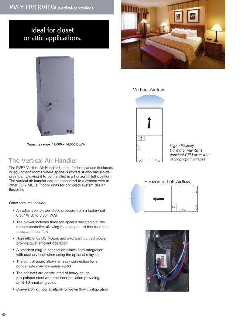
60
PVFY OVERVIEW (vertical-concealed)
Ideal for closet or attic applications.
The Vertical Air Handler
The PVFY Vertical Air Handler is ideal for installations in closets or equipment rooms where space is limited. It also has a side drain pan allowing it to be installed in a horizontal left position. The vertical air handler can be connected to a system with all other CITY MULTI indoor units for complete system design flexibility.
Other features include:
• An adjustable blower static pressure from a factory set 0.30" W.G. to 0.50" W.G.
• The blower includes three fan speeds selectable at the remote controller, allowing the occupant to fine-tune the occupant’s comfort
• High efficiency DC Motors and a forward curved blower provide quiet efficient operation
• A standard plug-in connection allows easy integration with auxiliary heat when using the optional relay kit.
• The control board allows an easy connection for a condensate overflow safety switch
• The cabinets are constructed of heavy gauge pre-painted steel with one-inch insulation providing an R-4.2 insulating value
• Conversion kit now available for down flow configuration
High efficiency DC motor maintains constant CFM even with varying input voltages
Vertical Airflow
Horizontal Left Airflow
Capacityrange:12,000–54,000Btu/h
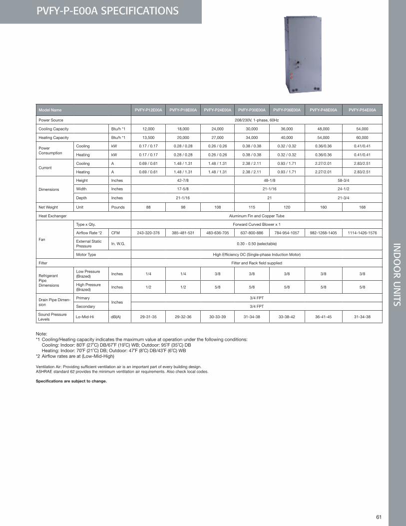
61
IND
OO
R UN
ITSPVFY-P-E00A SPECIFICATIONS
Model Name PVFY-P12E00A PVFY-P18E00A PVFY-P24E00A PVFY-P30E00A PVFY-P36E00A PVFY-P48E00A PVFY-P54E00A
Power Source 208/230V, 1-phase, 60Hz
Cooling Capacity Btu/h *1 12,000 18,000 24,000 30,000 36,000 48,000 54,000
Heating Capacity Btu/h *1 13,500 20,000 27,000 34,000 40,000 54,000 60,000
Power Consumption
Cooling kW 0.17 / 0.17 0.28 / 0.28 0.26 / 0.26 0.38 / 0.38 0.32 / 0.32 0.36/0.36 0.41/0.41
Heating kW 0.17 / 0.17 0.28 / 0.28 0.26 / 0.26 0.38 / 0.38 0.32 / 0.32 0.36/0.36 0.41/0.41
CurrentCooling A 0.69 / 0.61 1.48 / 1.31 1.48 / 1.31 2.38 / 2.11 0.93 / 1.71 2.27/2.01 2.83/2.51
Heating A 0.69 / 0.61 1.48 / 1.31 1.48 / 1.31 2.38 / 2.11 0.93 / 1.71 2.27/2.01 2.83/2.51
Dimensions
Height Inches 42-7/8 48-1/8 58-3/4
Width Inches 17-5/8 21-1/16 24-1/2
Depth Inches 21-1/16 21 21-3/4
Net Weight Unit Pounds 88 98 108 115 120 160 168
Heat Exchanger Aluminum Fin and Copper Tube
Fan
Type x Qty. Forward Curved Blower x 1
Airflow Rate *2 CFM 243-320-376 385-481-531 483-636-705 637-800-886 784-954-1057 982-1268-1405 1114-1426-1576
External Static Pressure
In. W.G. 0.30 - 0.50 (selectable)
Motor Type High Efficiency DC (Single-phase Induction Motor)
Filter Filter and Rack field supplied
Refrigerant Pipe Dimensions
Low Pressure (Brazed)
Inches 1/4 1/4 3/8 3/8 3/8 3/8 3/8
High Pressure (Brazed)
Inches 1/2 1/2 5/8 5/8 5/8 5/8 5/8
Drain Pipe Dimen-sion
PrimaryInches
3/4 FPT
Secondary 3/4 FPT
Sound Pressure Levels
Lo-Mid-Hi dB(A) 29-31-35 29-32-36 30-33-39 31-34-38 33-38-42 36-41-45 31-34-38
Note: *1 Cooling/Heating capacity indicates the maximum value at operation under the following conditions:
Cooling: Indoor: 80˚F (27˚C) DB/67˚F (19˚C) WB; Outdoor: 95˚F (35˚C) DBHeating: Indoor: 70˚F (21˚C) DB; Outdoor: 47˚F (8˚C) DB/43˚F (6˚C) WB
*2 Airflow rates are at (Low-Mid-High)
Ventilation Air: Providing sufficient ventilation air is an important part of every building design . ASHRAE standard 62 provides the minimum ventilation air requirements . Also check local codes .
Specificationsaresubjecttochange.
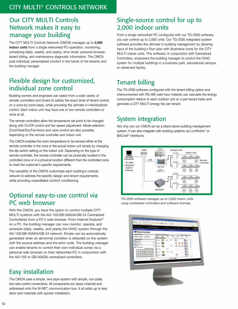
62
Our CITY MULTI Controls Network makes it easy to manage your building
CITY MULTI® CONTROLS NETWORK
The CITY MULTI Controls Network (CMCN) manages up to 2,000indoorunits from a single networked PC–operation, monitoring, scheduling (daily, weekly, and yearly), error email, personal browser, tenant billing, and maintenance diagnostic information. The CMCN puts individual, personalized comfort in the hands of the tenants and the building manager.
Flexible design for customized, individual zone control Building owners and engineers can select from a wide variety of remote controllers and timers to satisfy the exact level of tenant control on a zone-by-zone basis, while providing the ultimate in individualized control. Each indoor unit may have one or two remote controllers or none at all.
The remote controllers allow the temperature set point to be changed along with On/Off control and fan speed adjustment. Mode selection (Cool/Heat/Dry/Fan/Auto) and vane control are also possible, depending on the remote controller and indoor unit.
The CMCN enables the room temperature to be sensed either at the remote controller in the zone or the actual indoor unit simply by changing the dip switch setting on the indoor unit. Depending on the type of remote controller, the remote controller can be physically located in the controlled zone or in a physical location different than the controlled zone to meet the customer’s specific requirements.
The versatility of the CMCN customizes each building’s controls network to address the specific design and tenant requirements, while providing unparalleled comfort conditioning.
Optional easy-to-use control via PC web browserWith the CMCN, you have the option to control multiple CITY MULTI systems with the AG-150/GB-50ADA/GB-24 Centralized Controller(s) from a PC’s web browser. From Internet Explorer® on a PC, the building manager can now monitor, operate, and schedule (daily, weekly, and yearly) the HVAC system through the AG-150/GB-50ADA/GB-24 network. Emails can be automatically generated when an abnormal condition is detected on the system with the source address and the error code. The building manager can enable tenants to control their own individual zones via a personal web browser on their networked PC in conjunction with the AG-150 or GB-50ADA centralized controllers.
Easy installationThe CMCN uses a simple, two-pipe system with simple, non-polar, two-wire control connections. All components are daisy-chained and addressed onto the M-NET communication bus. It all adds up to less labor and materials with quicker installation.
Single-source control for up to 2,000 indoor unitsFrom a single networked PC configured with our TG-2000 software, you can control up to 2,000 units. Our TG-2000 integrated system software provides the ultimate in building management by allowing input of the building’s floor plan with illustrative icons for the CITY MULTI indoor units. This software, in conjunction with Centralized Controllers, empowers the building manager to control the HVAC system for multiple buildings in a business park, educational campus, or retirement facility.
Tenant billingThe TG-2000 software configured with the tenant billing option and interconnected with RS-485 watt-hour meter(s) can calculate the energy consumption relative to each outdoor unit on a per-tenant basis and generate a CITY MULTI energy fee per-tenant.
System integrationNot only can our CMCN act as a stand-alone building management system, it can also integrate with existing systems via LonWorks® or BACnet® interfaces.
TG-2000 software manages up to 2,000 indoor units using centralized controllers and software licenses.
GB-50ADA
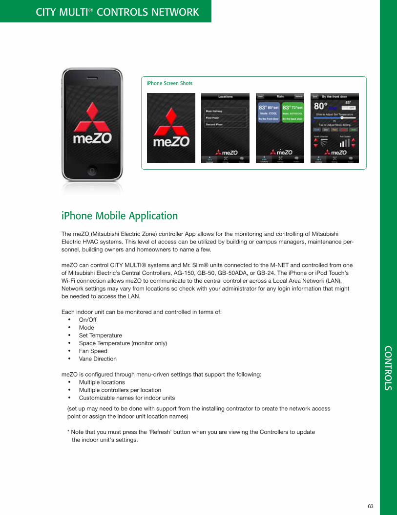
63
CITY MULTI® CONTROLS NETWORK C
ON
TROLS
iPhone Mobile Application
The meZO (Mitsubishi Electric Zone) controller App allows for the monitoring and controlling of Mitsubishi Electric HVAC systems. This level of access can be utilized by building or campus managers, maintenance per-sonnel, building owners and homeowners to name a few.
meZO can control CITY MULTI® systems and Mr. Slim® units connected to the M-NET and controlled from one of Mitsubishi Electric’s Central Controllers, AG-150, GB-50, GB-50ADA, or GB-24. The iPhone or iPod Touch’s Wi-Fi connection allows meZO to communicate to the central controller across a Local Area Network (LAN). Network settings may vary from locations so check with your administrator for any login information that might be needed to access the LAN.
Each indoor unit can be monitored and controlled in terms of: • On/Off• Mode • Set Temperature • Space Temperature (monitor only) • Fan Speed • Vane Direction
meZO is configured through menu-driven settings that support the following: • Multiple locations • Multiple controllers per location • Customizable names for indoor units
(set up may need to be done with support from the installing contractor to create the network access point or assign the indoor unit location names)
* Note that you must press the 'Refresh' button when you are viewing the Controllers to update the indoor unit's settings.
iPhone Screen Shots
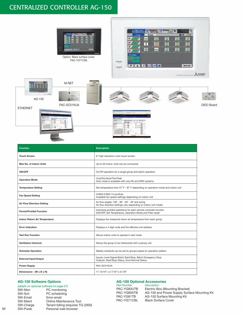
64
CENTRALIZED CONTROLLER AG-150
Option: Black surface cover. PAC-YG71CBL
AG-150
PAC-SC51KUAETHERNET
M-NET
Function Description
TouchScreen 9" high resolution color touch screen
MaxNo.ofIndoorUnits Up to 50 indoor units can be connected
ON/OFF On/Off operation for a single group and batch operation
OperationMode Cool/Dry/Auto/Fan/Heat Auto mode is available with only R2 and WR2 systems
TemperatureSetting Set temperature from 57˚ F - 87˚ F depending on operation mode and indoor unit
FanSpeedSetting Hi/Mid-2/Mid-1/Low/AutoAvailable fan speed settings depending on indoor unit
AirFlowDirectionSetting Air flow angles: 100˚ - 80˚ - 60˚ - 40˚ and swing Air flow direction settings vary depending on indoor unit model
Permit/ProhibitFunction Individual prohibit operations for each remote controller function (ON/OFF, Set Temperature, Operation Mode and Filter reset)
IndoorReturnAirTemperature Displays the measured return air temperature from each group
ErrorIndication Displays a 4 digit code and the affected unit address
TestRunFunction Allows indoor units to operate in test mode
VentilationInterlock Allows the group to be interlocked with Lossnay unit
ScheduleOperation Weekly schedule can be set by groups based on operation pattern
ExternalInput/Output Inputs: Level Signal-Batch Start/Stop, Batch Emergency Stop Outputs: Start/Stop Status, Error/Normal Status
PowerSupply PAC-SC51KUA
Dimensions-(WxDxH) 11-13/16" x 2-7/16" x 6-7/8"
AG-150SoftwareOptions
(details on optional software on page 67)SW-Mon PC monitoringSW-Sch PC schedulingSW-Email Error emailSW-Maint Online Maintenance ToolSW-Charge Tenant billing (requires TG-2000)SW-Pweb Personal web browser
AG-150OptionalAccessoriesPart Number DescriptionPAC-YG83UTB Electric Box (Mounting Bracket)PAC-YG85KTB AG-150 and Power Supply Surface Mounting KitPAC-YG81TB AG-150 Surface Mounting KitPAC-YG71CBL Black Surface Cover
79 ˚F
79 ˚F
82 ˚F
DIDO Board
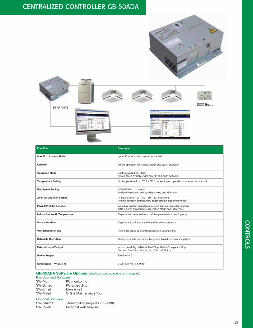
65
CO
NTRO
LS
DIDO BoardETHERNET
Function Description
MaxNo.ofIndoorUnits Up to 50 indoor units can be connected
ON/OFF On/Off operation for a single group and batch operation
OperationMode Cool/Dry/Auto/Fan/ Heat. Auto mode is available with only R2 and WR2 systems
TemperatureSetting Set temperature from 57˚ F - 87˚ F depending on operation mode and indoor unit
FanSpeedSetting Hi/Mid-2/Mid-1/Low/AutoAvailable fan speed settings depending on indoor unit
AirFlowDirectionSetting Air flow angles: 100˚ - 80˚ - 60˚ - 40˚ and swing Air flow direction settings vary depending on indoor unit model
Permit/ProhibitFunction Individual prohibit operations for each remote controller function (ON/OFF, Set Temperature, Operation Mode and Filter reset)
IndoorReturnAirTemperature Displays the measured return air temperature from each group
ErrorIndication Displays a 4 digit code and the affected unit address
VentilationInterlock Allows the group to be interlocked with Lossnay unit
ScheduleOperation Weekly schedule can be set by groups based on operation pattern
ExternalInput/Output Inputs: Level Signal-Batch Start/Stop, Batch Emergency Stop Outputs: Start/Stop Status, Error/Normal Status
PowerSupply 100-240 VAC
Dimensions-(WxDxH) 9-7/8" x 3-7/8" x 8-9/16"
CENTRALIZED CONTROLLER GB-50ADA
GB-50ADASoftwareOptions(details on optional software on page 67)Pre-Licensed SoftwareSW-Mon PC monitoringSW-Sched PC schedulingSW-Email Error emailSW-Maint Online Maintenance Tool
Optional SoftwareSW-Charge Tenant billing (requires TG-2000)SW-Pweb Personal web browser
79 ˚F
79 ˚F
82 ˚F
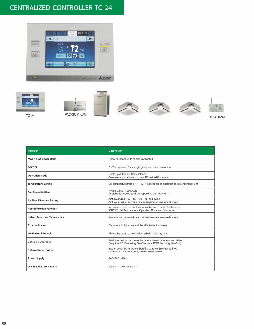
66
CENTRALIZED CONTROLLER TC-24
TC-24 DIDO Board
Function Description
MaxNo.ofIndoorUnits Up to 24 indoor units can be connected
ON/OFF On/Off operation for a single group and batch operation
OperationMode Cool/Dry/Auto/Fan/ Heat/Setback. Auto mode is available with only R2 and WR2 systems
TemperatureSetting Set temperature from 57˚ F - 87˚ F depending on operation mode and indoor unit
FanSpeedSetting Hi/Mid-2/Mid-1/Low/AutoAvailable fan speed settings depending on indoor unit
AirFlowDirectionSetting Air flow angles: 100˚ - 80˚ - 60˚ - 40˚ and swing Air flow direction settings vary depending on indoor unit model
Permit/ProhibitFunction Individual prohibit operations for each remote controller function (ON/OFF, Set Temperature, Operation Mode and Filter reset)
IndoorReturnAirTemperature Displays the measured return air temperature from each group
ErrorIndication Displays a 4 digit code and the affected unit address
VentilationInterlock Allows the group to be interlocked with Lossnay unit
ScheduleOperation Weekly schedule can be set by groups based on operation pattern *requires PC Monitoring (SW-Mon) and PC Scheduling (SW-Sch)
ExternalInput/Output Inputs: Level Signal-Batch Start/Stop, Batch Emergency Stop Outputs: Start/Stop Status, Error/Normal Status
PowerSupply PAC-SC51KUA
Dimensions-(WxDxH) 7-8/8" x 1-3/16" x 4-3/4"
PAC-SC51KUA
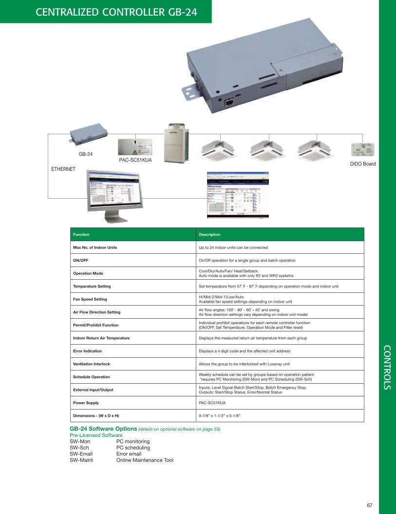
67
CENTRALIZED CONTROLLER GB-24
GB-24
DIDO BoardETHERNET
Function Description
MaxNo.ofIndoorUnits Up to 24 indoor units can be connected
ON/OFF On/Off operation for a single group and batch operation
OperationMode Cool/Dry/Auto/Fan/ Heat/Setback. Auto mode is available with only R2 and WR2 systems
TemperatureSetting Set temperature from 57˚ F - 87˚ F depending on operation mode and indoor unit
FanSpeedSetting Hi/Mid-2/Mid-1/Low/AutoAvailable fan speed settings depending on indoor unit
AirFlowDirectionSetting Air flow angles: 100˚ - 80˚ - 60˚ - 40˚ and swing Air flow direction settings vary depending on indoor unit model
Permit/ProhibitFunction Individual prohibit operations for each remote controller function (ON/OFF, Set Temperature, Operation Mode and Filter reset)
IndoorReturnAirTemperature Displays the measured return air temperature from each group
ErrorIndication Displays a 4 digit code and the affected unit address
VentilationInterlock Allows the group to be interlocked with Lossnay unit
ScheduleOperation Weekly schedule can be set by groups based on operation pattern *requires PC Monitoring (SW-Mon) and PC Scheduling (SW-Sch)
ExternalInput/Output Inputs: Level Signal-Batch Start/Stop, Batch Emergency Stop Outputs: Start/Stop Status, Error/Normal Status
PowerSupply PAC-SC51KUA
Dimensions-(WxDxH) 9-7/8" x 1-1/2" x 5-1/8"
GB-24SoftwareOptions(details on optional software on page 53)Pre-Licensed SoftwareSW-Mon PC monitoringSW-Sch PC schedulingSW-Email Error emailSW-Maint Online Maintenance Tool
79 ˚F
79 ˚F
82 ˚F
PAC-SC51KUA
CO
NTRO
LS
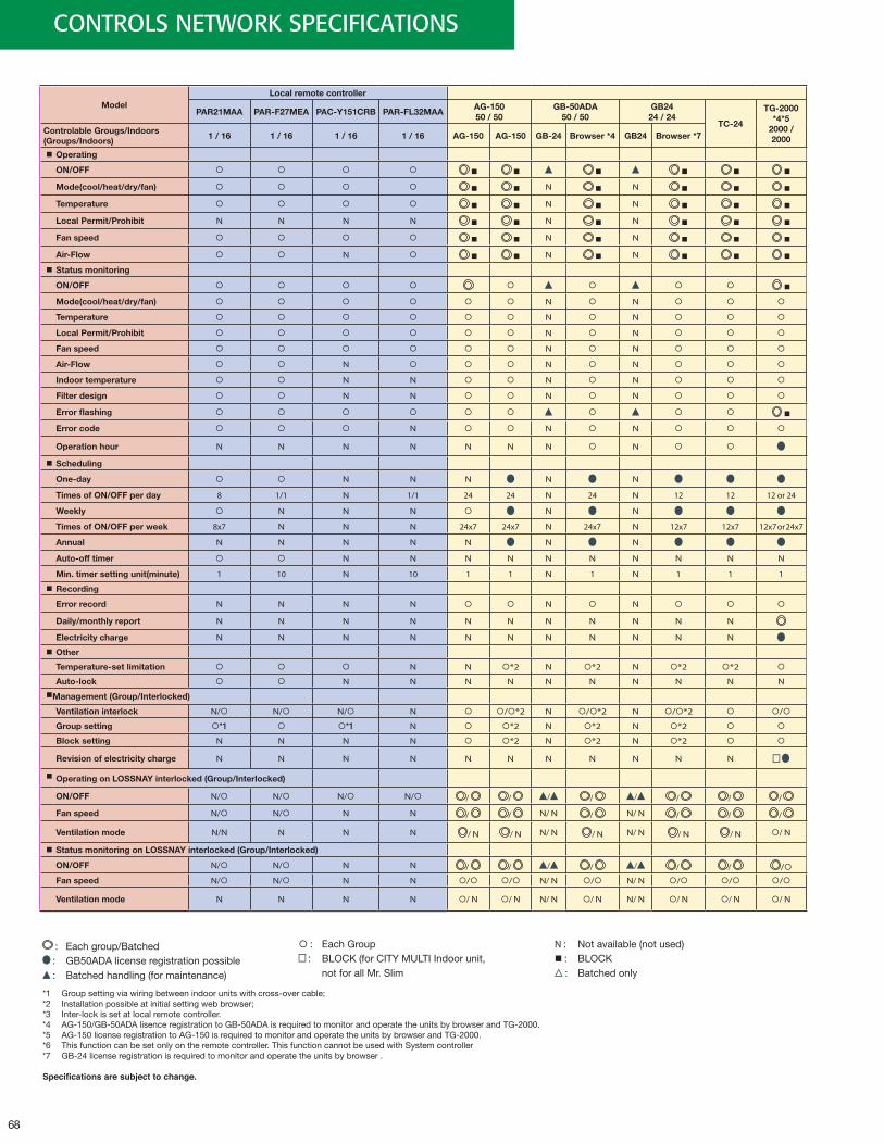
68
CONTROLS NETWORK SPECIFICATIONS
ModelLocalremotecontroller
PAR21MAA PAR-F27MEA PAC-Y151CRB PAR-FL32MAAAG-15050/50
GB-50ADA50/50
GB2424/24
TC-24
TG-2000*4*5
2000/2000
ControlableGrougs/Indoors(Groups/Indoors)
1/16 1/16 1/16 1/16 AG-150 AG-150 GB-24 Browser*4 GB24 Browser*7
Operating
ON/OFF
Mode(cool/heat/dry/fan) N N
Temperature N N
LocalPermit/Prohibit N N N N N N
Fanspeed N N
Air-Flow N N N
Statusmonitoring
ON/OFF
Mode(cool/heat/dry/fan) N N
Temperature N N
LocalPermit/Prohibit N N
Fanspeed N N
Air-Flow N N N
Indoortemperature N N N N
Filterdesign N N N N
Errorflashing
Errorcode N N N
Operationhour N N N N N N N N
Scheduling
One-day N N N N N
TimesofON/OFFperday 8 1/1 N 1/1 24 24 N 24 N 12 12 12 or 24
Weekly N N N N N
TimesofON/OFFperweek 8x7 N N N 24x7 24x7 N 24x7 N 12x7 12x7 12x7 or 24x7
Annual N N N N N N N
Auto-offtimer N N N N N N N N N N
Min.timersettingunit(minute) 1 10 N 10 1 1 N 1 N 1 1 1
Recording
Errorrecord N N N N N N
Daily/monthlyreport N N N N N N N N N N N
Electricitycharge N N N N N N N N N N N
Other
Temperature-setlimitation N N *2 N *2 N *2 *2
Auto-lock N N N N N N N N N N
Management(Group/Interlocked)
Ventilationinterlock N/ N/ N/ N /*2 N /*2 N /*2 /
Groupsetting *1 *1 N *2 N *2 N *2
Blocksetting N N N N *2 N *2 N *2
Revisionofelectricitycharge N N N N N N N N N N N
OperatingonLOSSNAYinterlocked(Group/Interlocked)
ON/OFF N/ N/ N/ N/ / / / / / / / /
Fanspeed N/ N/ N N / / N/ N / N/ N / / /
Ventilationmode N/N N N N / N / N N/ N / N N/ N / N / N / N
StatusmonitoringonLOSSNAYinterlocked(Group/Interlocked)
ON/OFF N/ N/ N N / / / / / / / /
Fanspeed N/ N/ N N / / N/ N / N/ N / / /
Ventilationmode N N N N / N / N N/ N / N N/ N / N / N / N
: Each group/Batched : GB50ADA license registration possible : Batched handling (for maintenance)
: Each Group : BLOCK (for CITY MULTI Indoor unit,
not for all Mr. Slim
N : Not available (not used) : BLOCK
: Batched only
*1 Group setting via wiring between indoor units with cross-over cable;*2 Installation possible at initial setting web browser;*3 Inter-lock is set at local remote controller.*4 AG-150/GB-50ADA lisence registration to GB-50ADA is required to monitor and operate the units by browser and TG-2000.*5 AG-150 license registration to AG-150 is required to monitor and operate the units by browser and TG-2000.*6 This function can be set only on the remote controller. This function cannot be used with System controller*7 GB-24 license registration is required to monitor and operate the units by browser .
Specifications are subject to change.
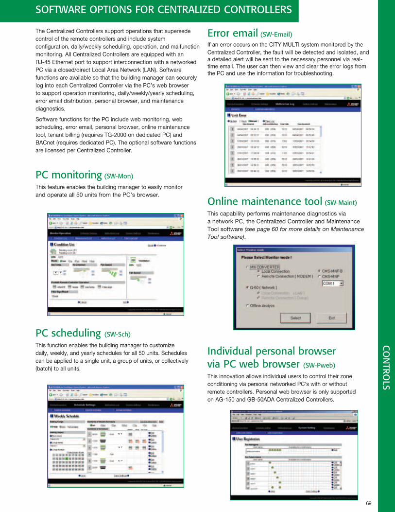
69
The Centralized Controllers support operations that supersede control of the remote controllers and include system configuration, daily/weekly scheduling, operation, and malfunction monitoring. All Centralized Controllers are equipped with an RJ-45 Ethernet port to support interconnection with a networked PC via a closed/direct Local Area Network (LAN). Software functions are available so that the building manager can securely log into each Centralized Controller via the PC’s web browser to support operation monitoring, daily/weekly/yearly scheduling, error email distribution, personal browser, and maintenance diagnostics.
Software functions for the PC include web monitoring, web scheduling, error email, personal browser, online maintenance tool, tenant billing (requires TG-2000 on dedicated PC) and BACnet (requires dedicated PC). The optional software functions are licensed per Centralized Controller.
PC monitoring (SW-Mon)
This feature enables the building manager to easily monitor and operate all 50 units from the PC’s browser.
PC scheduling (SW-Sch)
This function enables the building manager to customize daily, weekly, and yearly schedules for all 50 units. Schedules can be applied to a single unit, a group of units, or collectively (batch) to all units.
Error email (SW-Email)
If an error occurs on the CITY MULTI system monitored by the Centralized Controller, the fault will be detected and isolated, and a detailed alert will be sent to the necessary personnel via real-time email. The user can then view and clear the error logs from the PC and use the information for troubleshooting.
Online maintenance tool (SW-Maint)
This capability performs maintenance diagnostics via a network PC, the Centralized Controller and Maintenance Tool software (see page 60 for more details on Maintenance Tool software).
Individual personal browser via PC web browser (SW-Pweb)
This innovation allows individual users to control their zone conditioning via personal networked PC's with or without remote controllers. Personal web browser is only supported on AG-150 and GB-50ADA Centralized Controllers.
CO
NTRO
LSSOFTWARE OPTIONS FOR CENTRALIZED CONTROLLERS
81 °F
79 ˚F
79 ˚F
82 ˚F
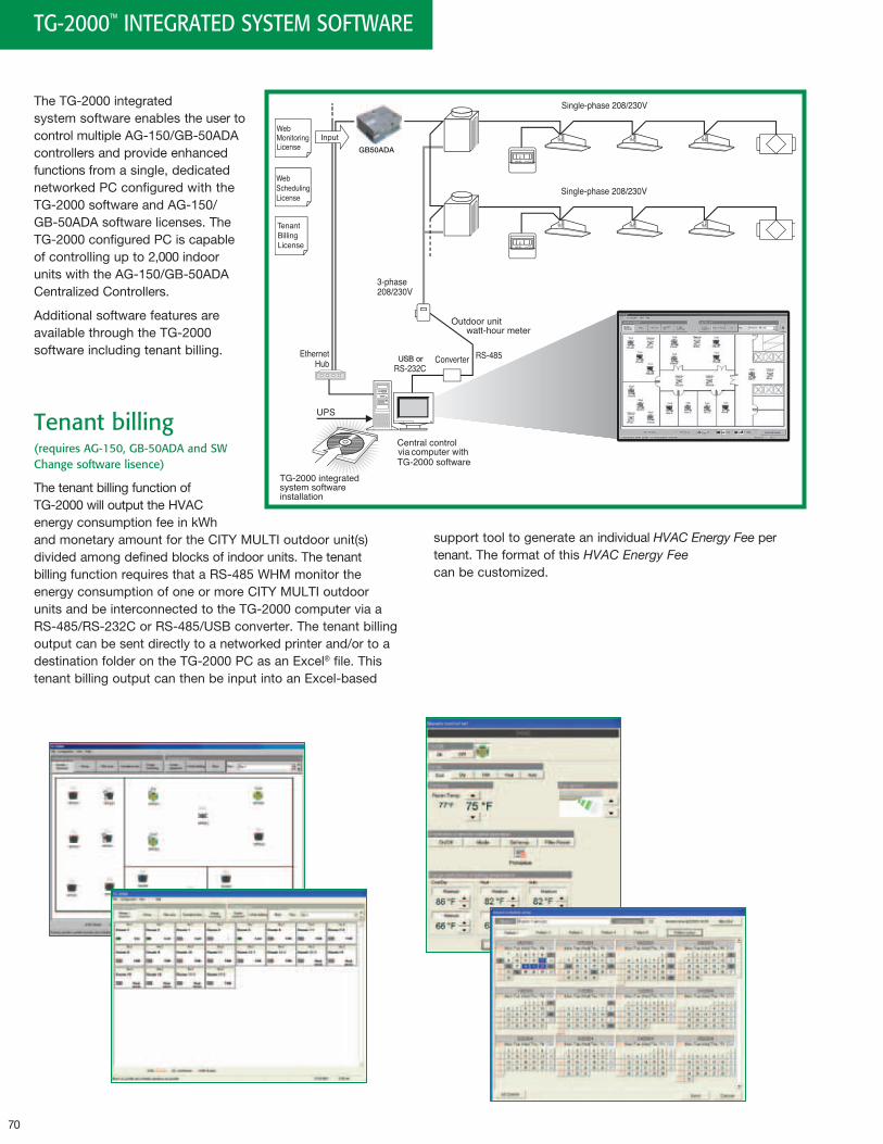
70
support tool to generate an individual HVAC Energy Fee per tenant. The format of this HVAC Energy Fee can be customized.
TG-2000™ INTEGRATED SYSTEM SOFTWARE
The TG-2000 integrated system software enables the user to control multiple AG-150/GB-50ADA controllers and provide enhanced functions from a single, dedicated networked PC configured with the TG-2000 software and AG-150/GB-50ADA software licenses. The TG-2000 configured PC is capable of controlling up to 2,000 indoor units with the AG-150/GB-50ADA Centralized Controllers.
Additional software features are available through the TG-2000 software including tenant billing.
Tenant billing (requires AG-150, GB-50ADA and SW Change software lisence)
The tenant billing function of TG-2000 will output the HVAC energy consumption fee in kWh and monetary amount for the CITY MULTI outdoor unit(s) divided among defined blocks of indoor units. The tenant billing function requires that a RS-485 WHM monitor the energy consumption of one or more CITY MULTI outdoor units and be interconnected to the TG-2000 computer via a RS-485/RS-232C or RS-485/USB converter. The tenant billing output can be sent directly to a networked printer and/or to a destination folder on the TG-2000 PC as an Excel® file. This tenant billing output can then be input into an Excel-based
USB or
UP
POWER RATING
MODEL
WEIGHTSERIAL No.
2.11kg
POWER SUPPLY UNIT
MITSUBISHI ELECTRIC CORPORATION
PAC-SC50KUA
GB50ADA
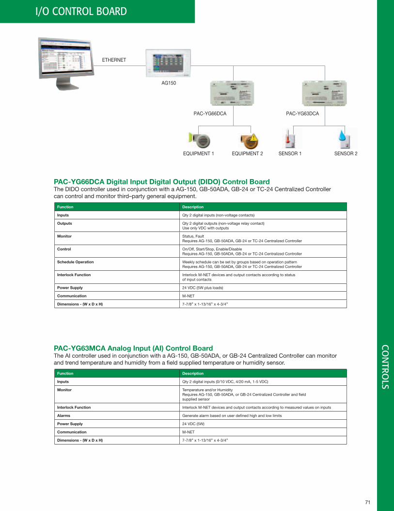
71
CO
NTRO
LSI/O CONTROL BOARD
Function Description
Inputs Qty 2 digital inputs (non-voltage contacts)
Outputs Qty 2 digital outputs (non-voltage relay contact)Use only VDC with outputs
Monitor Status, FaultRequires AG-150, GB-50ADA, GB-24 or TC-24 Centralized Controller
Control On/Off, Start/Stop, Enable/DisableRequires AG-150, GB-50ADA, GB-24 or TC-24 Centralized Controller
ScheduleOperation Weekly schedule can be set by groups based on operation patternRequires AG-150, GB-50ADA, GB-24 or TC-24 Centralized Controller
InterlockFunction Interlock M-NET devices and output contacts according to status of input contacts
PowerSupply 24 VDC (5W plus loads)
Communication M-NET
Dimensions-(WxDxH) 7-7/8" x 1-13/16" x 4-3/4"
Function Description
Inputs Qty 2 digital inputs (0/10 VDC, 4/20 mA, 1-5 VDC)
Monitor Temperature and/or HumidityRequires AG-150, GB-50ADA, or GB-24 Centralized Controller and field supplied sensor
InterlockFunction Interlock M-NET devices and output contacts according to measured values on inputs
Alarms Generate alarm based on user defined high and low limits
PowerSupply 24 VDC (5W)
Communication M-NET
Dimensions-(WxDxH) 7-7/8" x 1-13/16" x 4-3/4"
PAC-YG66DCADigitalInputDigitalOutput(DIDO)ControlBoardThe DIDO controller used in conjunction with a AG-150, GB-50ADA, GB-24 or TC-24 Centralized Controller can control and monitor third–party general equipment.
PAC-YG63MCAAnalogInput(AI)ControlBoardThe AI controller used in conjunction with a AG-150, GB-50ADA, or GB-24 Centralized Controller can monitor and trend temperature and humidity from a field supplied temperature or humidity sensor.
ETHERNET
AG150
PAC-YG66DCA PAC-YG63DCA
SENSOR 1EQUIPMENT 1 SENSOR 2EQUIPMENT 2
!
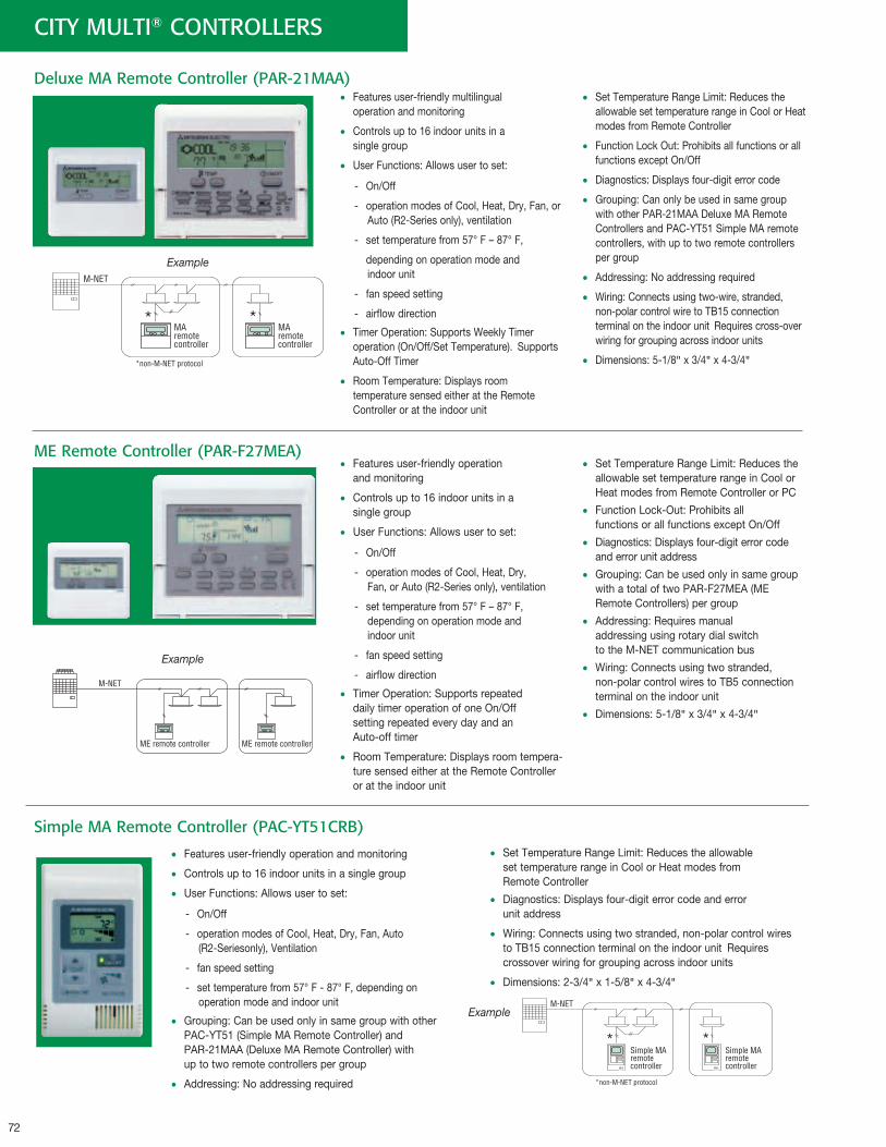
72
• Features user-friendly operation and monitoring
• Controls up to 16 indoor units in a single group
• User Functions: Allows user to set:
- On/Off
- operation modes of Cool, Heat, Dry, Fan, Auto (R2-Seriesonly), Ventilation
- fan speed setting
- set temperature from 57° F - 87° F, depending on operation mode and indoor unit
• Grouping: Can be used only in same group with other PAC-YT51 (Simple MA Remote Controller) and PAR-21MAA (Deluxe MA Remote Controller) with up to two remote controllers per group
• Addressing: No addressing required
• Set Temperature Range Limit: Reduces the allowable set temperature range in Cool or Heat modes from Remote Controller
• Diagnostics: Displays four-digit error code and error unit address
• Wiring: Connects using two stranded, non-polar control wires to TB15 connection terminal on the indoor unit Requires crossover wiring for grouping across indoor units
• Dimensions: 2-3/4" x 1-5/8" x 4-3/4"
CITY MULTI® CONTROLLERS
Deluxe MA Remote Controller (PAR-21MAA)
ME Remote Controller (PAR-F27MEA)
• Features user-friendly multilingual operation and monitoring
• Controls up to 16 indoor units in a single group
• User Functions: Allows user to set:
- On/Off
- operation modes of Cool, Heat, Dry, Fan, or Auto (R2-Series only), ventilation
- set temperature from 57° F – 87° F,
depending on operation mode and indoor unit
- fan speed setting
- airflow direction
• Timer Operation: Supports Weekly Timer operation (On/Off/Set Temperature). Supports Auto-Off Timer
• Room Temperature: Displays room temperature sensed either at the Remote Controller or at the indoor unit
• Set Temperature Range Limit: Reduces the allowable set temperature range in Cool or Heat modes from Remote Controller
• Function Lock Out: Prohibits all functions or all functions except On/Off
• Diagnostics: Displays four-digit error code
• Grouping: Can only be used in same group with other PAR-21MAA Deluxe MA Remote Controllers and PAC-YT51 Simple MA remote controllers, with up to two remote controllers per group
• Addressing: No addressing required
• Wiring: Connects using two-wire, stranded, non-polar control wire to TB15 connection terminal on the indoor unit Requires cross-over wiring for grouping across indoor units
• Dimensions: 5-1/8" x 3/4" x 4-3/4"
• Features user-friendly operation and monitoring
• Controls up to 16 indoor units in a single group
• User Functions: Allows user to set:
- On/Off
- operation modes of Cool, Heat, Dry, Fan, or Auto (R2-Series only), ventilation
- set temperature from 57° F – 87° F, depending on operation mode and indoor unit
- fan speed setting
- airflow direction
• Timer Operation: Supports repeated daily timer operation of one On/Off setting repeated every day and an Auto-off timer
• Room Temperature: Displays room tempera-ture sensed either at the Remote Controller or at the indoor unit
• Set Temperature Range Limit: Reduces the allowable set temperature range in Cool or Heat modes from Remote Controller or PC
• Function Lock-Out: Prohibits all functions or all functions except On/Off
• Diagnostics: Displays four-digit error code and error unit address
• Grouping: Can be used only in same group with a total of two PAR-F27MEA (ME Remote Controllers) per group
• Addressing: Requires manual addressing using rotary dial switch to the M-NET communication bus
• Wiring: Connects using two stranded, non-polar control wires to TB5 connection terminal on the indoor unit
• Dimensions: 5-1/8" x 3/4" x 4-3/4"
Example
Example
Simple MA Remote Controller (PAC-YT51CRB)
Example
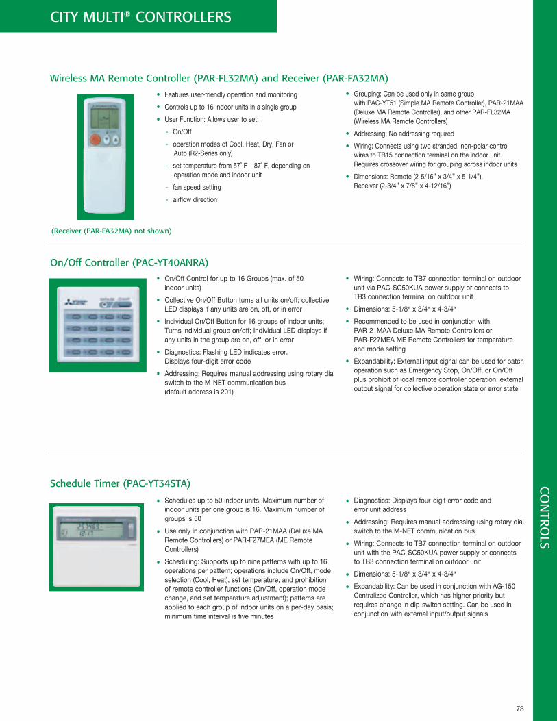
73
CO
NTRO
LSCITY MULTI® CONTROLLERS
• Features user-friendly operation and monitoring
• Controls up to 16 indoor units in a single group
• User Function: Allows user to set:
- On/Off
- operation modes of Cool, Heat, Dry, Fan or Auto (R2-Series only)
- set temperature from 57˚ F – 87˚ F, depending on operation mode and indoor unit
- fan speed setting
- airflow direction
• Grouping: Can be used only in same group with PAC-YT51 (Simple MA Remote Controller), PAR-21MAA (Deluxe MA Remote Controller), and other PAR-FL32MA (Wireless MA Remote Controllers)
• Addressing: No addressing required
• Wiring: Connects using two stranded, non-polar control wires to TB15 connection terminal on the indoor unit. Requires crossover wiring for grouping across indoor units
• Dimensions: Remote (2-5/16" x 3/4" x 5-1/4"), Receiver (2-3/4" x 7/8" x 4-12/16")
• Schedules up to 50 indoor units. Maximum number of indoor units per one group is 16. Maximum number of groups is 50
• Use only in conjunction with PAR-21MAA (Deluxe MA Remote Controllers) or PAR-F27MEA (ME Remote Controllers)
• Scheduling: Supports up to nine patterns with up to 16 operations per pattern; operations include On/Off, mode selection (Cool, Heat), set temperature, and prohibition of remote controller functions (On/Off, operation mode change, and set temperature adjustment); patterns are applied to each group of indoor units on a per-day basis; minimum time interval is five minutes
• Diagnostics: Displays four-digit error code and error unit address
• Addressing: Requires manual addressing using rotary dial switch to the M-NET communication bus.
• Wiring: Connects to TB7 connection terminal on outdoor unit with the PAC-SC50KUA power supply or connects to TB3 connection terminal on outdoor unit
• Dimensions: 5-1/8" x 3/4" x 4-3/4"
• Expandability: Can be used in conjunction with AG-150 Centralized Controller, which has higher priority but requires change in dip-switch setting. Can be used in conjunction with external input/output signals
On/Off Controller (PAC-YT40ANRA)
Wireless MA Remote Controller (PAR-FL32MA) and Receiver (PAR-FA32MA)
(Receiver (PAR-FA32MA) not shown)
• On/Off Control for up to 16 Groups (max. of 50 indoor units)
• Collective On/Off Button turns all units on/off; collective LED displays if any units are on, off, or in error
• Individual On/Off Button for 16 groups of indoor units; Turns individual group on/off; Individual LED displays if any units in the group are on, off, or in error
• Diagnostics: Flashing LED indicates error. Displays four-digit error code
• Addressing: Requires manual addressing using rotary dial switch to the M-NET communication bus (default address is 201)
• Wiring: Connects to TB7 connection terminal on outdoor unit via PAC-SC50KUA power supply or connects to TB3 connection terminal on outdoor unit
• Dimensions: 5-1/8" x 3/4" x 4-3/4"
• Recommended to be used in conjunction with PAR-21MAA Deluxe MA Remote Controllers or PAR-F27MEA ME Remote Controllers for temperature and mode setting
• Expandability: External input signal can be used for batch operation such as Emergency Stop, On/Off, or On/Off plus prohibit of local remote controller operation, external output signal for collective operation state or error state
Schedule Timer (PAC-YT34STA)
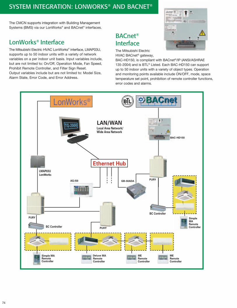
74
SYSTEM INTEGRATION: LONWORKS® AND BACNET®
The CMCN supports integration with Building Management Systems (BMS) via our LonWorks® and BACnet® interfaces.
LonWorks® InterfaceThe Mitsubishi Electric HVAC LonWorks® interface, LMAP03U, supports up to 50 indoor units with a variety of network variables on a per indoor unit basis. Input variables include, but are not limited to: On/Off, Operation Mode, Fan Speed, Prohibit Remote Controller, and Filter Sign Reset. Output variables include but are not limited to: Model Size, Alarm State, Error Code, and Error Address.
BACnet®
InterfaceThe Mitsubishi Electric HVAC BACnet® gateway, BAC-HD150, is compliant with BACnet®/IP (ANSI/ASHRAE 135-2004) and is BTL® Listed. Each BAC-HD150 can support up to 50 indoor units with a variety of object types. Operation and monitoring points available include ON/OFF, mode, space temperature set point, prohibition of remote controller functions, error codes and alarms.
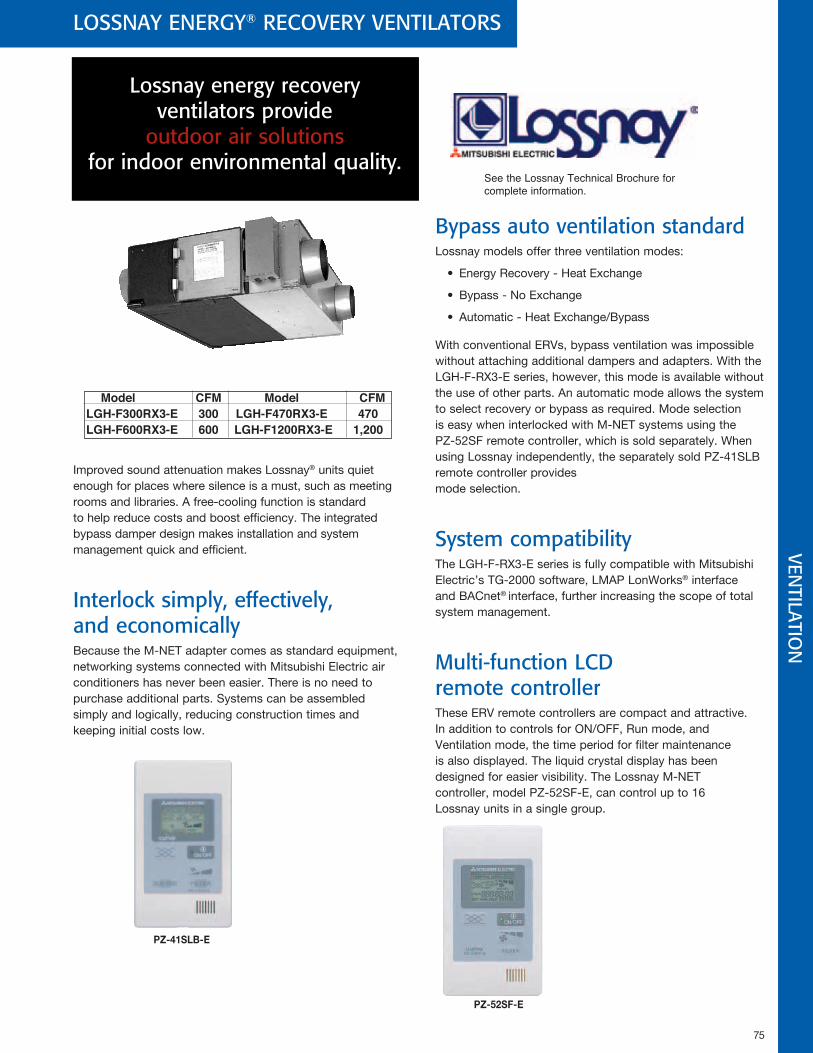
75
LOSSNAY ENERGY® RECOVERY VENTILATORS
Improved sound attenuation makes Lossnay® units quiet enough for places where silence is a must, such as meeting rooms and libraries. A free-cooling function is standard to help reduce costs and boost efficiency. The integrated bypass damper design makes installation and system management quick and efficient.
Interlock simply, effectively, and economicallyBecause the M-NET adapter comes as standard equipment, networking systems connected with Mitsubishi Electric air conditioners has never been easier. There is no need to purchase additional parts. Systems can be assembled simply and logically, reducing construction times and keeping initial costs low.
Bypass auto ventilation standardLossnay models offer three ventilation modes:
• Energy Recovery - Heat Exchange
• Bypass - No Exchange
• Automatic - Heat Exchange/Bypass
With conventional ERVs, bypass ventilation was impossible without attaching additional dampers and adapters. With the LGH-F-RX3-E series, however, this mode is available without the use of other parts. An automatic mode allows the system to select recovery or bypass as required. Mode selection is easy when interlocked with M-NET systems using the PZ-52SF remote controller, which is sold separately. When using Lossnay independently, the separately sold PZ-41SLB remote controller provides mode selection.
System compatibilityThe LGH-F-RX3-E series is fully compatible with Mitsubishi Electric’s TG-2000 software, LMAP LonWorks® interface and BACnet® interface, further increasing the scope of total system management.
Multi-function LCD remote controllerThese ERV remote controllers are compact and attractive. In addition to controls for ON/OFF, Run mode, and Ventilation mode, the time period for filter maintenance is also displayed. The liquid crystal display has been designed for easier visibility. The Lossnay M-NET controller, model PZ-52SF-E, can control up to 16 Lossnay units in a single group.
See the Lossnay Technical Brochure for complete information .
Model CFM Model CFMLGH-F300RX3-E 300 LGH-F470RX3-E 470 LGH-F600RX3-E 600 LGH-F1200RX3-E 1,200
Lossnay energy recovery ventilators provide
outdoor air solutions for indoor environmental quality.
VENTILATIO
N
Lossnay® remote controller (PZ-41SLB-E)
Lossnay® M-NET remote controller (PZ-52SF-E)
Source power requirement
Interface condition fortransmission line
Number of Lossnay® units controlled by PZ-41SLB-E
Input voltage: 9VDC-15VDC, 0.02APower received from a Lossnay® unit, TM2 5 - 6
Specialized transmission line:DC power + AM modulation
1-15
Source power requirement
Interface condition fortransmission line
Number of M-NET controlled Lossnay® units controlled by PZ-52SF-E
Input voltage: 17VDC-30VDC, 0.02A Power received from an outdoor unit or a power supply unit via M-NET transmission line M-NET transmission line: 30VDC + AMI signal (±5VDC) 1-15
Unit: inches mm
2-3/4 70
1-7/8 48
3/8 8
1-5/16 33
4-3/
4 12
0
Unit: inches mm
2-3/4 70
1-7/8 48
3/8 8
1-5/16 33
4-3/
4 12
0
PZ-41SLB-E
PZ-52SF-E
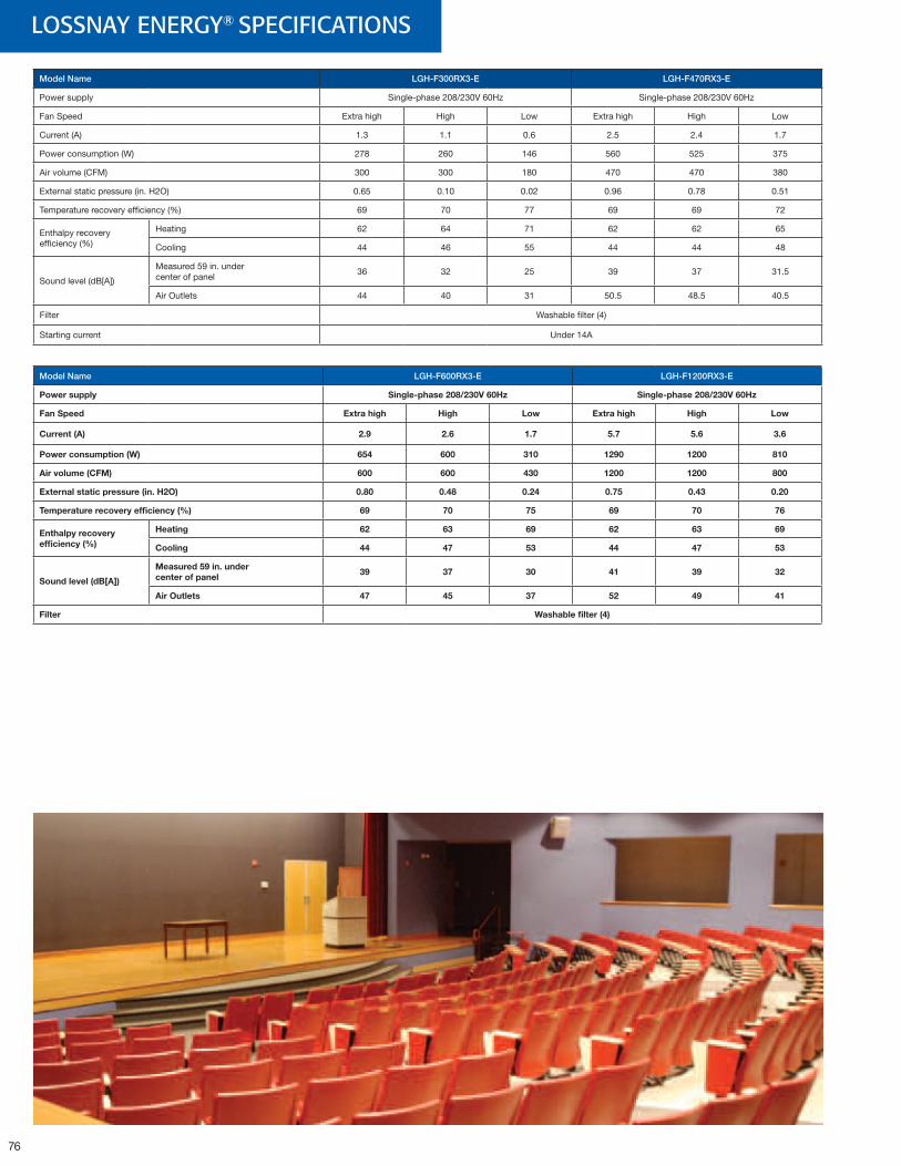
76
LOSSNAY ENERGY® SPECIFICATIONS
Model Name LGH-F300RX3-E LGH-F470RX3-E
Power supply Single-phase 208/230V 60Hz Single-phase 208/230V 60Hz
Fan Speed Extra high High Low Extra high High Low
Current (A) 1.3 1.1 0.6 2.5 2.4 1.7
Power consumption (W) 278 260 146 560 525 375
Air volume (CFM) 300 300 180 470 470 380
External static pressure (in. H2O) 0.65 0.10 0.02 0.96 0.78 0.51
Temperature recovery efficiency (%) 69 70 77 69 69 72
Enthalpy recoveryefficiency (%)
Heating 62 64 71 62 62 65
Cooling 44 46 55 44 44 48
Sound level (dB[A])
Measured 59 in. undercenter of panel
36 32 25 39 37 31.5
Air Outlets 44 40 31 50.5 48.5 40.5
Filter Washable filter (4)
Starting current Under 14A
Model Name LGH-F600RX3-E LGH-F1200RX3-E
Powersupply Single-phase208/230V60Hz Single-phase208/230V60Hz
FanSpeed Extrahigh High Low Extrahigh High Low
Current(A) 2.9 2.6 1.7 5.7 5.6 3.6
Powerconsumption(W) 654 600 310 1290 1200 810
Airvolume(CFM) 600 600 430 1200 1200 800
Externalstaticpressure(in.H2O) 0.80 0.48 0.24 0.75 0.43 0.20
Temperaturerecoveryefficiency(%) 69 70 75 69 70 76
Enthalpyrecoveryefficiency(%)
Heating 62 63 69 62 63 69
Cooling 44 47 53 44 47 53
Soundlevel(dB[A])
Measured59in.undercenterofpanel
39 37 30 41 39 32
AirOutlets 47 45 37 52 49 41
Filter Washablefilter(4)
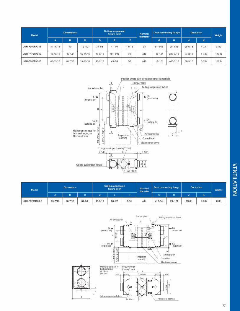
77
VENTILATIO
N
ModelDimensions
Ceilingsuspensionfixturepitch Nominal
diameter
Ductconnectingflange DuctpitchWeight
A B C D E F G H J K
LGH-F300RX3-E 34-15/16 40 12-1/2 31-1/8 41-1/4 1-9/16 ø8 ø7-9/16 ø8-3/16 29-5/16 4-7/8 73 lb
LGH-F470RX3-E 45-13/16 39-1/2 15-11/16 40-9/16 40-13/16 3/8 ø10 ø9-1/2 ø10-3/16 27-3/16 5-7/8 143 lb
LGH-F600RX3-E 45-13/16 48-7/16 15-11/16 40-9/16 49-3/4 3/8 ø10 ø9-1/2 ø10-3/16 36-3/16 5-7/8 159 lb
ModelDimensions
Ceiling suspensionfixture pitch Nominal
diameter
Duct connecting flange Duct pitchWeight
A B C D E F G H J K
LGH-F1200RX3-E 65-7/16 48-7/16 31-1/2 40-9/16 50-1/8 8-3/4 ø14 ø13-3/4 29- 1/8 395 lb 4-7/8 73 lb
Air exhaust fan
Position where duct direction change is possible
Air supply fan
Damper plate
Ceiling suspension fixture
Maintenance cover
Control box
Maintenance space forheat exchanger, air filters,and fans
Energy exchanger (Lossnay® core)3-1/8"3-1/8"
23-5
/8" o
r mor
e
5-7/
8" ~
9-1
3/16
"
7/8"
EB J
Inspectionopening
EA(exhaust air)
OA(outside air)
RA(return air)
SA(supply air)
DK
K
KA
Air filters
Ceiling suspension fixture G H
FC
Air exhaust fan
Air supply fan
Damper plate
Ceiling suspension fixture
Maintenance cover
Control box
Maintenance space forheat exchanger,air filters,and fans
Energy exchanger(Lossnay® core)
B
Inspectionopening
EA(exhaust air)
OA(outside air)
RA(return air)
SA(supply air)
Air filters
Ceiling suspension fixture
23-5
/8" o
r mor
e
C
F
A9-13/16"
D
5-7/
8" ~
9-1
3/16
"
ø13-
3/4"
5-1/8"45-13/16"9-13/16"5-1/8"
Power cord opening
27-3
/4"
29-1
/8"
47"
1"E
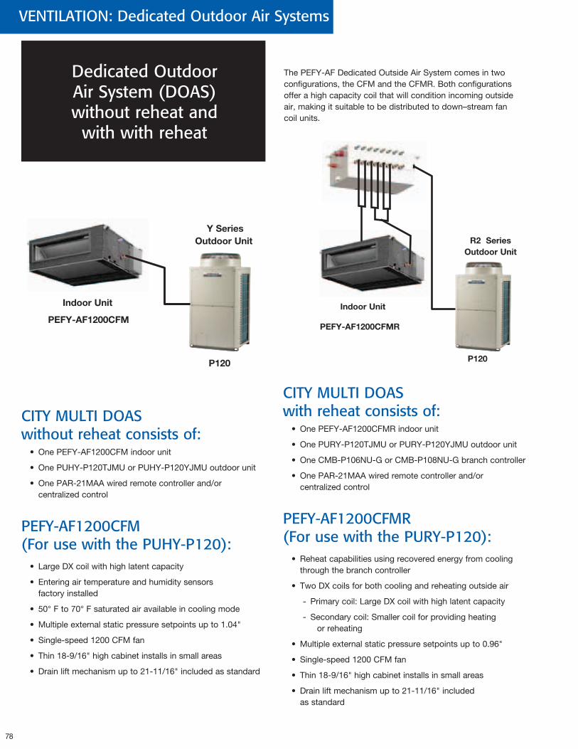
78
VENTILATION: Dedicated Outdoor Air Systems
The PEFY-AF Dedicated Outside Air System comes in two configurations, the CFM and the CFMR. Both configurations offer a high capacity coil that will condition incoming outside air, making it suitable to be distributed to down–stream fan coil units.
P120
PEFY-AF1200CFM
YSeriesOutdoorUnit
IndoorUnit
CITY MULTI DOAS without reheat consists of:
• One PEFY-AF1200CFM indoor unit
• One PUHY-P120TJMU or PUHY-P120YJMU outdoor unit
• One PAR-21MAA wired remote controller and/or centralized control
PEFY-AF1200CFM (For use with the PUHY-P120):
• Large DX coil with high latent capacity
• Entering air temperature and humidity sensors factory installed
• 50° F to 70° F saturated air available in cooling mode
• Multiple external static pressure setpoints up to 1.04"
• Single-speed 1200 CFM fan
• Thin 18-9/16" high cabinet installs in small areas
• Drain lift mechanism up to 21-11/16" included as standard
CITY MULTI DOAS with reheat consists of:
• One PEFY-AF1200CFMR indoor unit
• One PURY-P120TJMU or PURY-P120YJMU outdoor unit
• One CMB-P106NU-G or CMB-P108NU-G branch controller
• One PAR-21MAA wired remote controller and/or centralized control
PEFY-AF1200CFMR (For use with the PURY-P120):
• Reheat capabilities using recovered energy from cooling through the branch controller
• Two DX coils for both cooling and reheating outside air
- Primary coil: Large DX coil with high latent capacity
- Secondary coil: Smaller coil for providing heating or reheating
• Multiple external static pressure setpoints up to 0.96"
• Single-speed 1200 CFM fan
• Thin 18-9/16" high cabinet installs in small areas
• Drain lift mechanism up to 21-11/16" included as standard
Dedicated Outdoor Air System (DOAS) without reheat and
with with reheat
R2SeriesOutdoorUnit
P120
PEFY-AF1200CFMR
IndoorUnit
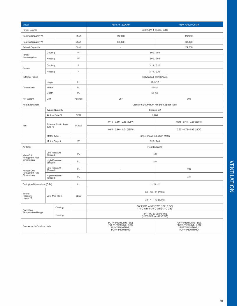
79
VENTILATIO
N
Model PEFY-AF1200CFM PEFY-AF1200CFMR
Power Source 208/230V, 1-phase, 60Hz
Cooling Capacity *1 Btu/h 112,000 112,000
Heating Capacity *1 Btu/h 61,400 61,400
Reheat Capacity Btu/h - 24,200
Power Consumption
Cooling W 660 / 780
Heating W 660 / 780
CurrentCooling A 3.19 / 3.45
Heating A 3.19 / 3.45
External Finish Galvanized-steel Sheets
Dimensions
Height In. 18-9/16
Width In. 49-1/4
Depth In. 55-1/8
Net Weight Unit Pounds 287 309
Heat Exchanger Cross Fin (Aluminum Fin and Copper Tube)
Fan
Type x Quantity Sirocco x 2
Airflow Rate *2 CFM 1,200
External Static Pres-sure *3 In.WG
0.40 - 0.60 - 0.88 (208V) 0.28 - 0.48 - 0.80 (280V)
0.64 - 0.80 - 1.04 (230V) 0.52 - 0.72- 0.96 (230V)
Motor Type Singe-phase Induction Motor
Motor Output W 620 / 740
Air Filter Field Supplied
Main CoilRefrigerant Pipe Dimensions
Low Pressure (Brazed) In. 7/8
High Pressure (Brazed) In. 3/8
Reheat CoilRefrigerant Pipe Dimensions
Low Pressure (Brazed) In. - 7/8
High Pressure (Brazed) In. - 3/8
Drainpipe Dimensions (O.D.) In. 1-1/4 x 2
Sound Pressure Levels *3
Low-Mid-High dB(A)
36 - 38 - 41 (208V)
39 - 41 - 43 (230V)
Operating Temperature Range
Cooling 50° F WB to 95° F WB (109° F DB)(10°C WB to 35°C WB [43°C DB])
Heating -4° F WB to +60° F WB(-20°C WB to +16°C WB)
Connectable Outdoor Units
PUHY-P120TJMU (-BS),PUHY-P120YJMU (-BS)
PUHY-P120THMUPUHY-P120YHMU
PURY-P120TJMU (-BS),PURY-P120YJMU (-BS)
PURY-P120THMUPURY-P120YHMU
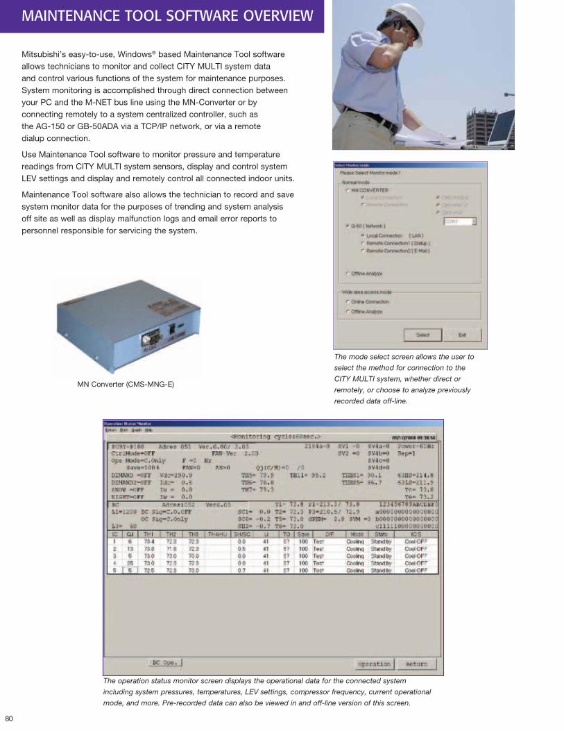
80
Mitsubishi’s easy-to-use, Windows® based Maintenance Tool software allows technicians to monitor and collect CITY MULTI system data and control various functions of the system for maintenance purposes. System monitoring is accomplished through direct connection between your PC and the M-NET bus line using the MN-Converter or by connecting remotely to a system centralized controller, such as the AG-150 or GB-50ADA via a TCP/IP network, or via a remote dialup connection.
Use Maintenance Tool software to monitor pressure and temperature readings from CITY MULTI system sensors, display and control system LEV settings and display and remotely control all connected indoor units.
Maintenance Tool software also allows the technician to record and save system monitor data for the purposes of trending and system analysis off site as well as display malfunction logs and email error reports to personnel responsible for servicing the system.
The mode select screen allows the user to
select the method for connection to the
CITY MULTI system, whether direct or
remotely, or choose to analyze previously
recorded data off-line.
MN Converter (CMS-MNG-E)
The operation status monitor screen displays the operational data for the connected system
including system pressures, temperatures, LEV settings, compressor frequency, current operational
mode, and more. Pre-recorded data can also be viewed in and off-line version of this screen.
MAINTENANCE TOOL SOFTWARE OVERVIEW
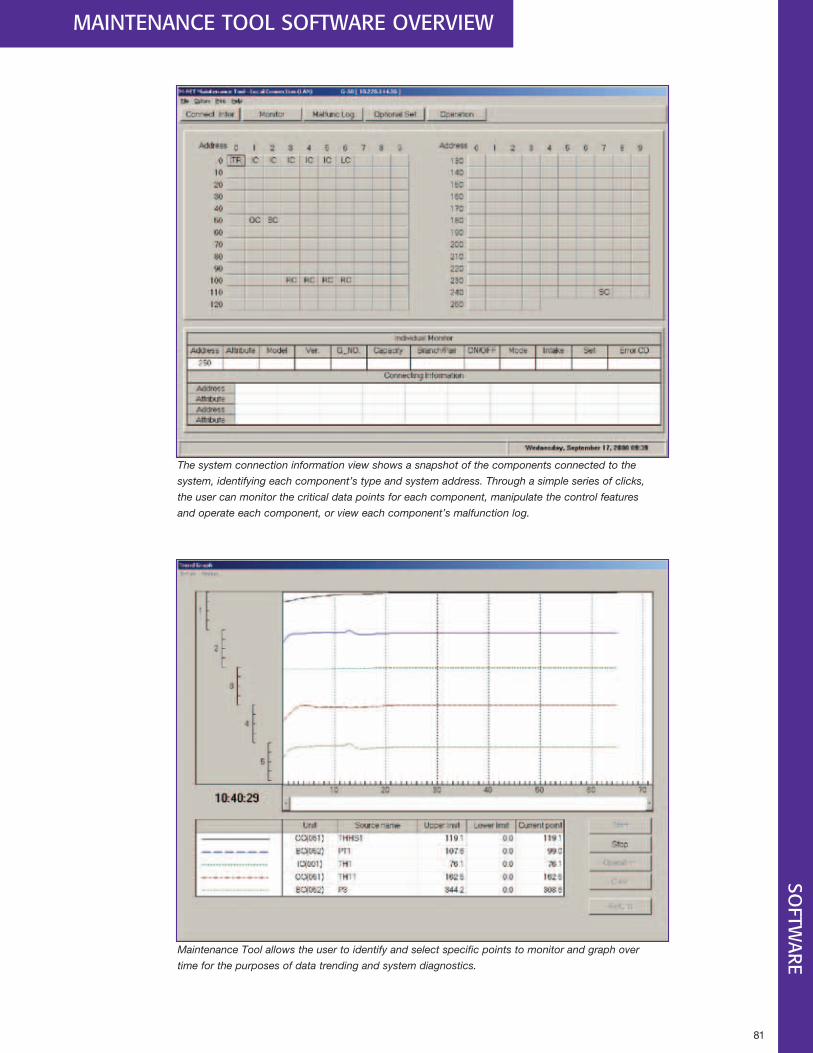
81
SOFTW
ARE
The system connection information view shows a snapshot of the components connected to the
system, identifying each component’s type and system address. Through a simple series of clicks,
the user can monitor the critical data points for each component, manipulate the control features
and operate each component, or view each component’s malfunction log.
Maintenance Tool allows the user to identify and select specific points to monitor and graph over
time for the purposes of data trending and system diagnostics.
MAINTENANCE TOOL SOFTWARE OVERVIEW
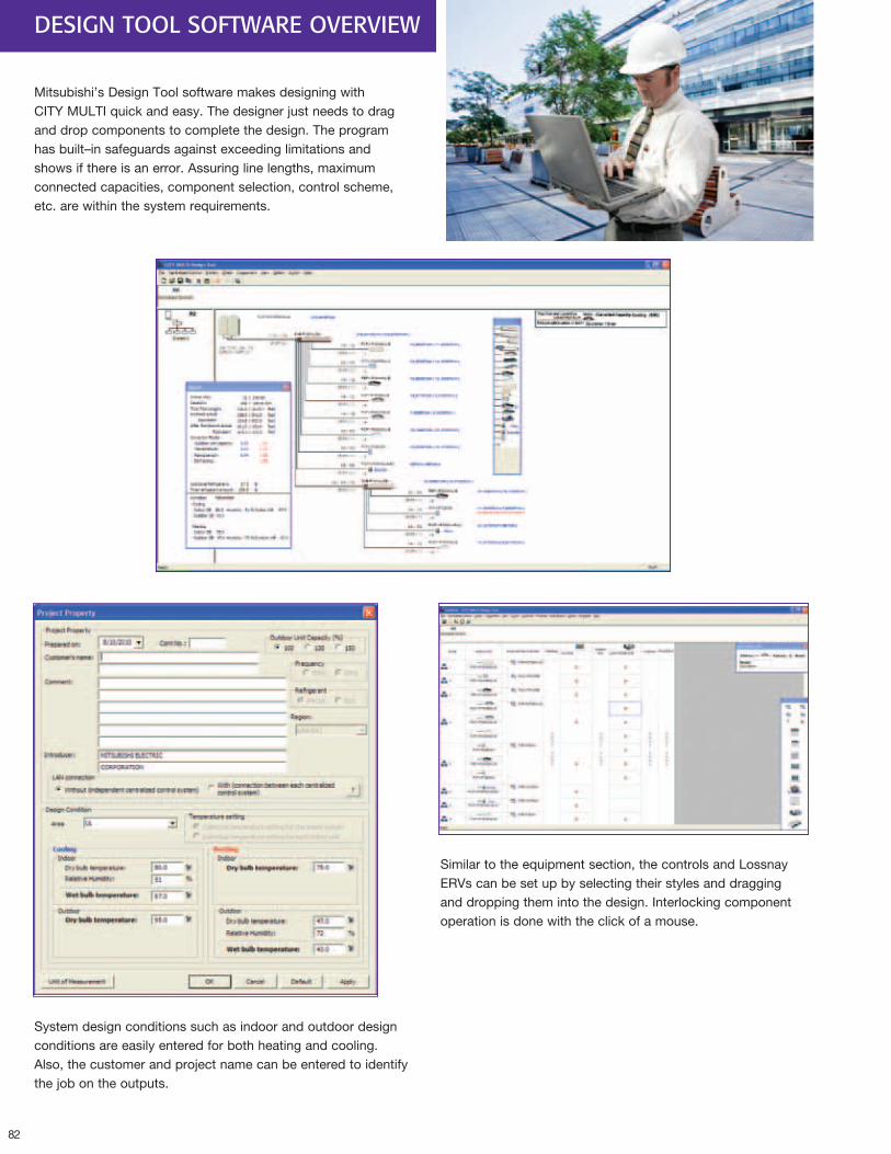
82
DESIGN TOOL SOFTWARE OVERVIEW
Mitsubishi’s Design Tool software makes designing with CITY MULTI quick and easy. The designer just needs to drag and drop components to complete the design. The program has built–in safeguards against exceeding limitations and shows if there is an error. Assuring line lengths, maximum connected capacities, component selection, control scheme, etc. are within the system requirements.
System design conditions such as indoor and outdoor design conditions are easily entered for both heating and cooling. Also, the customer and project name can be entered to identify the job on the outputs.
Similar to the equipment section, the controls and Lossnay ERVs can be set up by selecting their styles and dragging and dropping them into the design. Interlocking component operation is done with the click of a mouse.
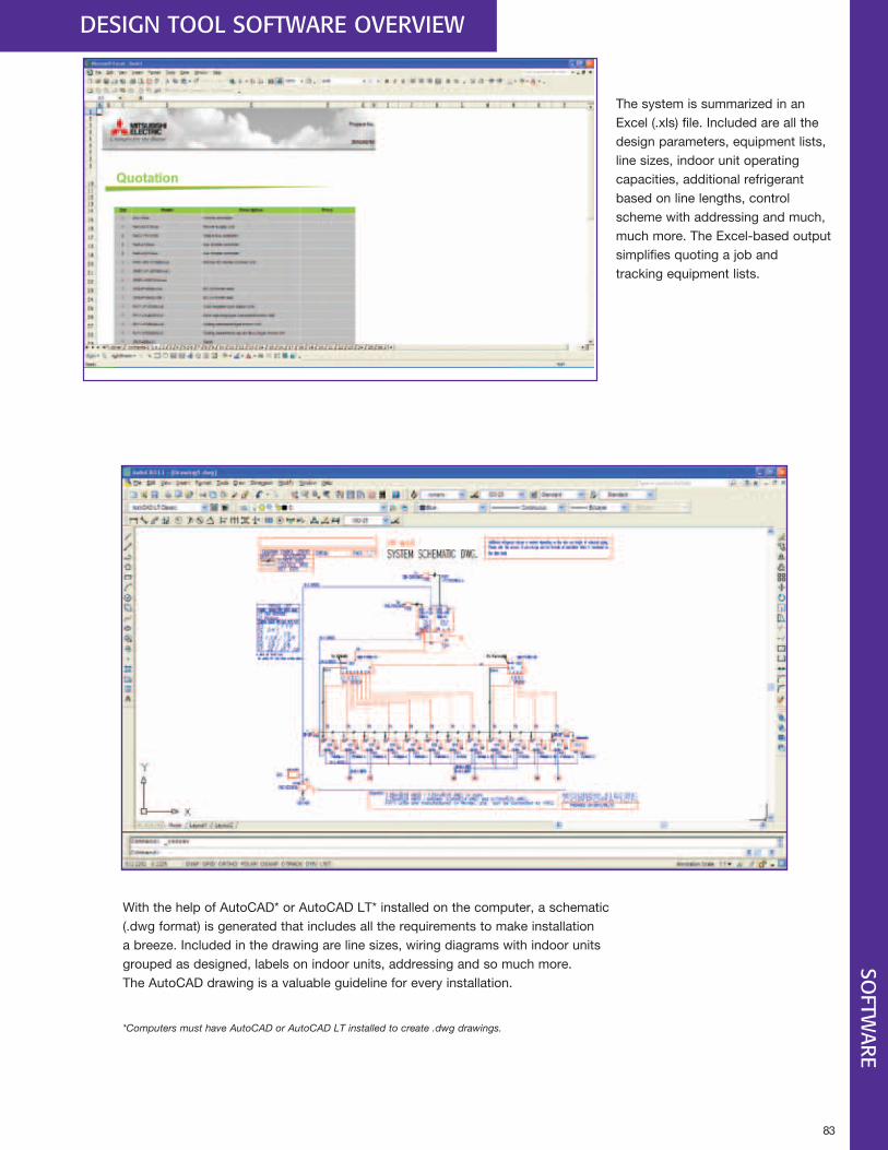
83
DESIGN TOOL SOFTWARE OVERVIEWSO
FTWARE
The system is summarized in an Excel (.xls) file. Included are all the design parameters, equipment lists, line sizes, indoor unit operating capacities, additional refrigerant based on line lengths, control scheme with addressing and much, much more. The Excel-based output simplifies quoting a job and tracking equipment lists.
With the help of AutoCAD* or AutoCAD LT* installed on the computer, a schematic (.dwg format) is generated that includes all the requirements to make installation a breeze. Included in the drawing are line sizes, wiring diagrams with indoor units grouped as designed, labels on indoor units, addressing and so much more. The AutoCAD drawing is a valuable guideline for every installation.
*Computers must have AutoCAD or AutoCAD LT installed to create .dwg drawings.
Mitsubishi Electric Air Conditioning & Refrigeration Systems WorksacquiredISO9001certificationunderSeries9000oftheinternationalStandardOrganization(ISO),basedonareviewofqualitywarrantiesfortheproductionofrefrigerationandairconditioningequipment.
ISO Authorization SystemTheISO9000seriesisaplantauthorizationsystemrelatingtoqualitywarrantiesasstipulatedbytheISO.ISO9001certifiesqualitywarrantiesbasedonthe"design,development,production,installationandauxiliaryservices"forproductsbuiltatanauthorizedplant.
Mitsubishi Electric Air Conditioning & Refrigeration SystemsWorksacquiredenvironmentalmanagementsystemstandardISO14001certification.
TheISO14000seriesisasetofstandardsapplyingtoenvironmentalprotectionsetbytheInternationalStandardOrganization(ISO).
Certificate Number EC97J1227Certificate Number FM33568
Seecompletewarrantyforterms,conditions,andlimitations.AcopyisavailablefromMitsubishiElectric,3400LawrencevilleSuwaneeRoad,Suwanee,GA30024 Please recycle.
©2010MitsubishiElectricandElectronicsUSA,Inc.CITYMULTIisaregisteredtrademarkofMitsubishiElectric.MitsubishiElectricisaregisteredtrademarkofMitsubishiElectricCorporation.Thethree-diamondlogoisaregisteredlogoofMitsubishiElectricCorporation.
WindowsandExcelareregisteredtrademarksoftheMicrosoftCorporation.AutoCADisaregisteredtrademarkofAutodesk.LON,LONWORKS®,andtheEchelonlogoaretrademarksofEchelonCorporation,registeredintheUnitedStatesandothercountries.BACnet®isaregis-teredtrademarkoftheAmericanSocietyofHeating,Refrigerating,andAir-ConditioningEngineers(ASHRAE).
Specificationsshowninthisbrochurearesubjecttochangewithoutnotice.
CMTECH-10-09-30M PD
MitsubishiElectric&ElectronicsUSA,Inc.www.mitsubishipro.com