technical brochure engineering - composite...
TRANSCRIPT
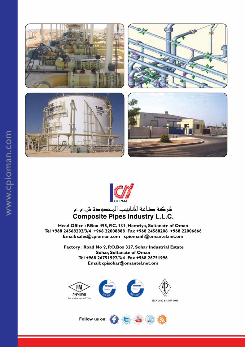
www.cpioman.com44 Years Experience
Head Office : P.Box 495, P.C. 131, Hamriya, Sultanate of OmanTel +968 24568202/3/4 +968 22008888 Fax +968 24568208 +968 22006666
Email: [email protected] [email protected]
Factory : Road No 9, P.O.Box 327, Sohar Industrial EstateSohar, Sultanate of Oman
Tel +968 26751992/3/4 Fax +968 26751996Email: [email protected]
15LR-0030 & 15HR-0031Refer to official listing on FM Web
Follow us on:
LEA
DER
S IN
MA
NU
FAC
TU
RIN
G F
IBER
GLA
SS P
IPES
ww
w.c
pio
man
.co
m
TECHNICAL BROCHUREENGINEERING
CONTENTIntroduction 2Certification & Accrediation 3Product Feature and Benefits 4Product Application 5Applicable Standards 6Material 8Temperature Limitations for GRP 9Product Design 10
Mechanical Properties 18CPI Product Range 19
�
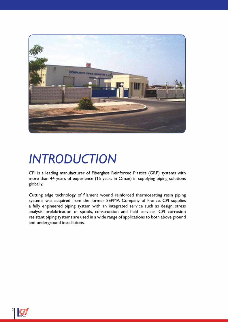
IntroductIonCPI is a leading manufacturer of Fiberglass Reinforced Plastics (GRP) systems with more than 44 years of experience (15 years in Oman) in supplying piping solutions globally.
Cutting edge technology of filament wound reinforced thermosetting resin piping systems was acquired from the former SEPMA Company of France. CPI supplies a fully engineered piping system with an integrated service such as design, stress analysis, prefabrication of spools, construction and field services. CPI corrosion resistant piping systems are used in a wide range of applications to both above ground and underground installations.
�
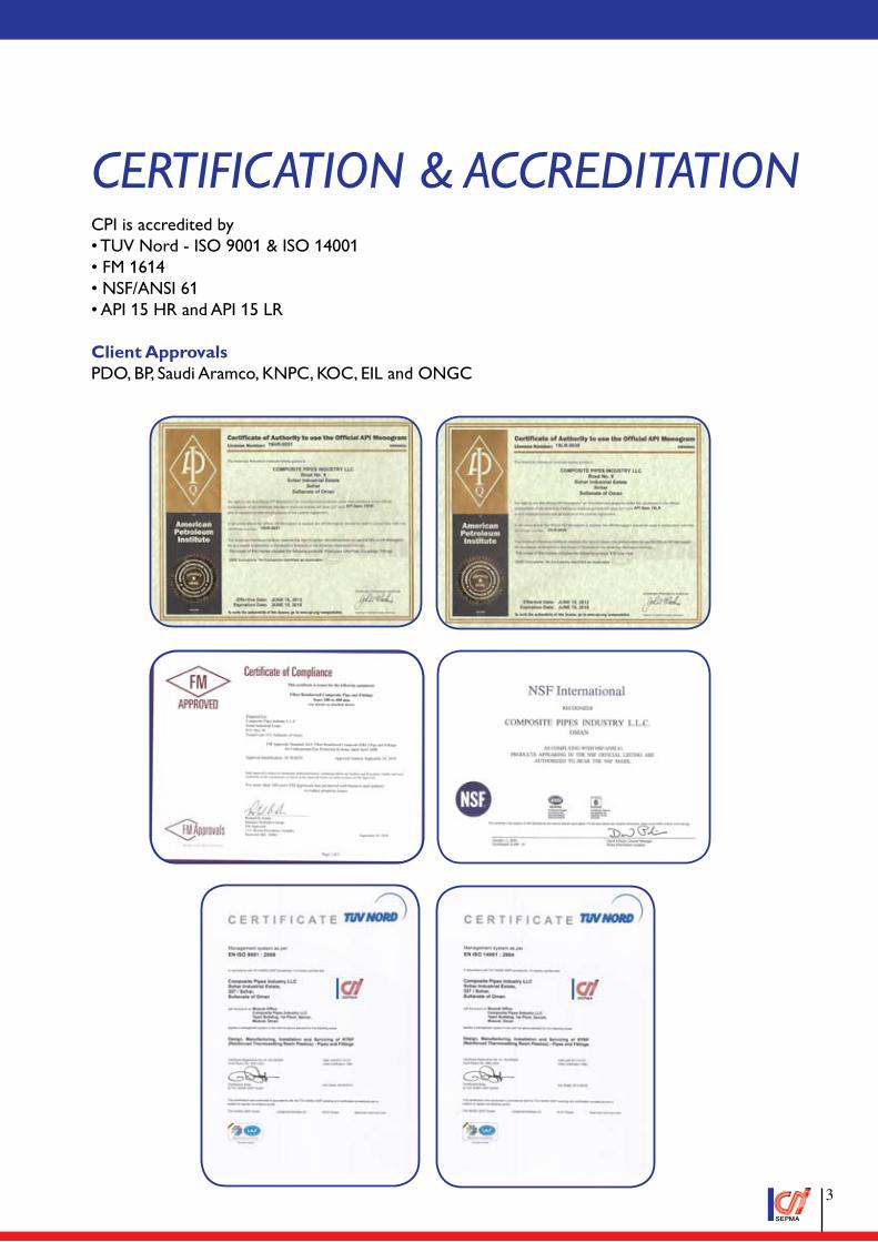
certIfIcatIon & accredItatIonCPI is accredited by• TUV Nord - ISO 9001 & ISO 14001• FM 1614• NSF/ANSI 61• API 15 HR and API 15 LR
Client ApprovalsPDO, BP, Saudi Aramco, KNPC, KOC, EIL and ONGC
�
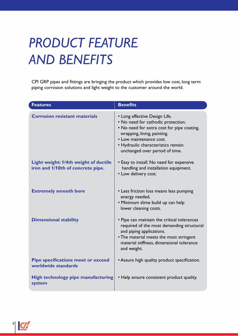
Product feature and BenefIts
CPI GRP pipes and fittings are bringing the product which provides low cost, long term piping corrosion solutions and light weight to the customer around the world.
Features Benefits
Corrosion resistant materials • Long effective Design Life. • No need for cathodic protection. • No need for extra cost for pipe coating, wrapping, lining, painting. • Low maintenance cost. • Hydraulic characteristics remain unchanged over period of time.
Light weight: 1/4th weight of ductile • Easy to install. No need for expensiveiron and 1/10th of concrete pipe. handling and installation equipment. • Low delivery cost.
Extremely smooth bore • Less friction loss means less pumping energy needed. • Minimum slime build up can help lower cleaning costs.
Dimensional stability • Pipe can maintain the critical tolerances required of the most demanding structural and piping applications. • The material meets the most stringent material stiffness, dimensional tolerance and weight.
Pipe specifications meet or exceed • Assure high quality product specification. worldwide standards
High technology pipe manufacturing • Help ensure consistent product quality.system
�
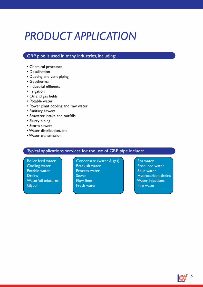
Product aPPlIcatIon
GRP pipe is used in many industries, including:
• Chemical processes• Desalination• Ducting and vent piping• Geothermal• Industrial effluents• Irrigation• Oil and gas fields• Potable water• Power plant cooling and raw water• Sanitary sewers• Seawater intake and outfalls• Slurry piping• Storm sewers• Water distribution, and• Water transmission.
Typical applications services for the use of GRP pipe include:
Boiler feed water Condensate (water & gas) Sea waterCooling water Brackish water Produced waterPotable water Process water Sour waterDrains Sewer Hydrocarbon drainsWater/oil mixtures Flow lines Water injectionsGlycol Fresh water Fire water
�
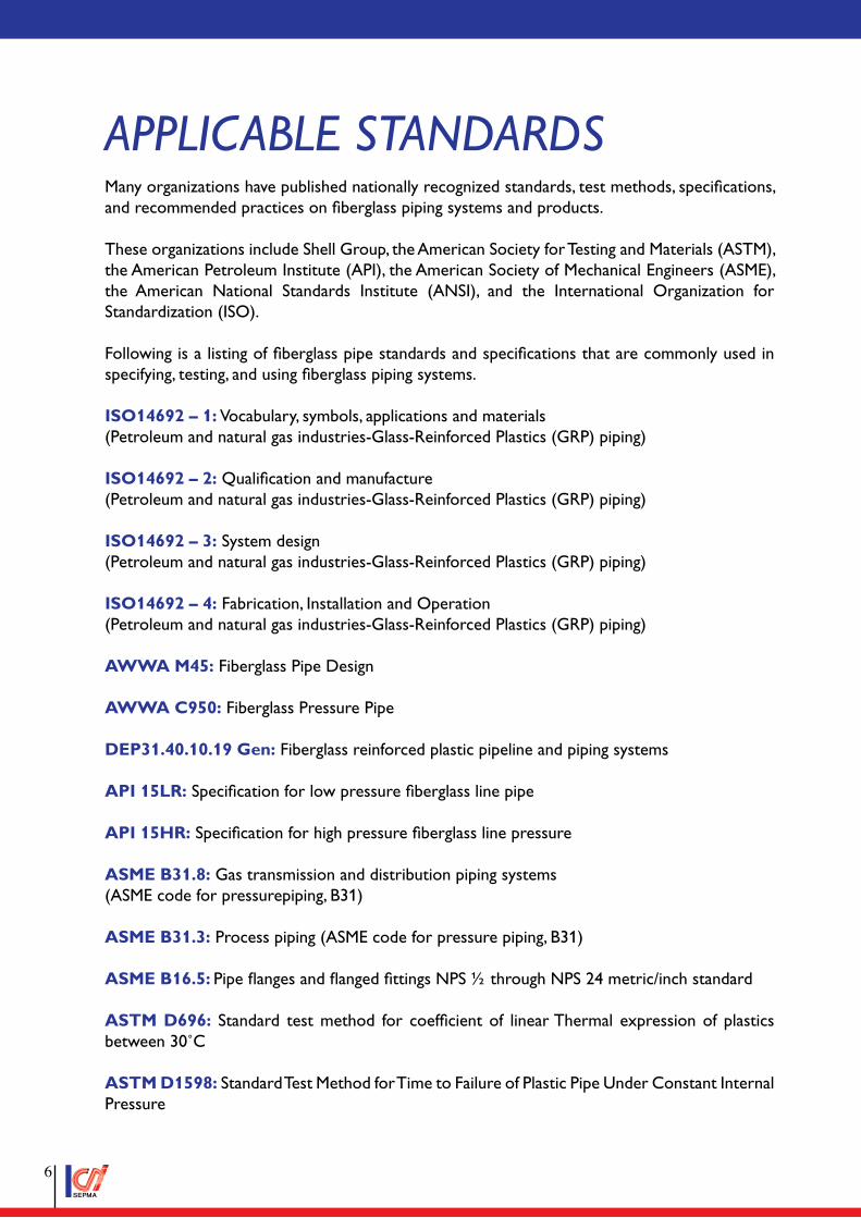
aPPlIcaBle standardsMany organizations have published nationally recognized standards, test methods, specifications, and recommended practices on fiberglass piping systems and products.
These organizations include Shell Group, the American Society for Testing and Materials (ASTM), the American Petroleum Institute (API), the American Society of Mechanical Engineers (ASME), the American National Standards Institute (ANSI), and the International Organization for Standardization (ISO).
Following is a listing of fiberglass pipe standards and specifications that are commonly used in specifying, testing, and using fiberglass piping systems.
ISO14692 – 1: Vocabulary, symbols, applications and materials (Petroleum and natural gas industries-Glass-Reinforced Plastics (GRP) piping)
ISO14692 – 2: Qualification and manufacture (Petroleum and natural gas industries-Glass-Reinforced Plastics (GRP) piping)
ISO14692 – 3: System design (Petroleum and natural gas industries-Glass-Reinforced Plastics (GRP) piping)
ISO14692 – 4: Fabrication, Installation and Operation (Petroleum and natural gas industries-Glass-Reinforced Plastics (GRP) piping)
AWWA M45: Fiberglass Pipe Design
AWWA C950: Fiberglass Pressure Pipe
DEP31.40.10.19 Gen: Fiberglass reinforced plastic pipeline and piping systems
API 15LR: Specification for low pressure fiberglass line pipe
API 15HR: Specification for high pressure fiberglass line pressure
ASME B31.8: Gas transmission and distribution piping systems (ASME code for pressurepiping, B31)
ASME B31.3: Process piping (ASME code for pressure piping, B31)
ASME B16.5: Pipe flanges and flanged fittings NPS ½ through NPS 24 metric/inch standard
ASTM D696: Standard test method for coefficient of linear Thermal expression of plastics between 30˚C
ASTM D1598: Standard Test Method for Time to Failure of Plastic Pipe Under Constant Internal Pressure
�
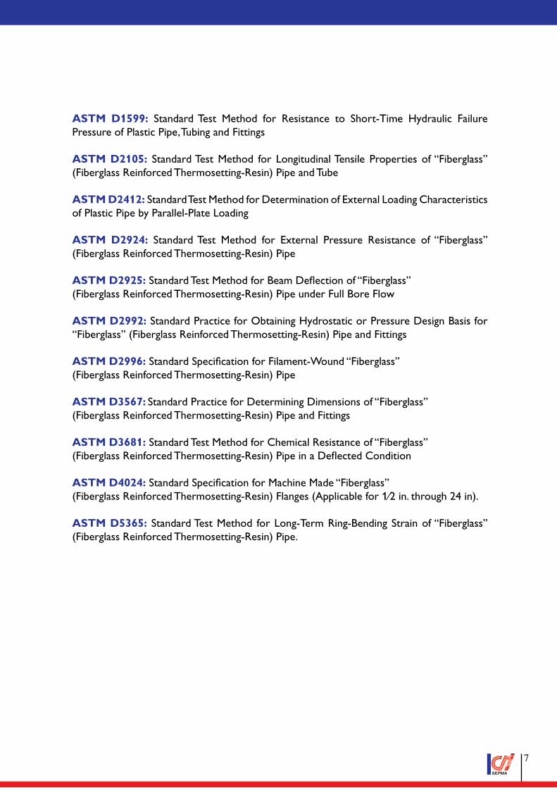
ASTM D1599: Standard Test Method for Resistance to Short-Time Hydraulic Failure Pressure of Plastic Pipe, Tubing and Fittings
ASTM D2105: Standard Test Method for Longitudinal Tensile Properties of “Fiberglass” (Fiberglass Reinforced Thermosetting-Resin) Pipe and Tube
ASTM D2412: Standard Test Method for Determination of External Loading Characteristics of Plastic Pipe by Parallel-Plate Loading
ASTM D2924: Standard Test Method for External Pressure Resistance of “Fiberglass” (Fiberglass Reinforced Thermosetting-Resin) Pipe
ASTM D2925: Standard Test Method for Beam Deflection of “Fiberglass” (Fiberglass Reinforced Thermosetting-Resin) Pipe under Full Bore Flow
ASTM D2992: Standard Practice for Obtaining Hydrostatic or Pressure Design Basis for “Fiberglass” (Fiberglass Reinforced Thermosetting-Resin) Pipe and Fittings
ASTM D2996: Standard Specification for Filament-Wound “Fiberglass” (Fiberglass Reinforced Thermosetting-Resin) Pipe
ASTM D3567: Standard Practice for Determining Dimensions of “Fiberglass” (Fiberglass Reinforced Thermosetting-Resin) Pipe and Fittings
ASTM D3681: Standard Test Method for Chemical Resistance of “Fiberglass” (Fiberglass Reinforced Thermosetting-Resin) Pipe in a Deflected Condition
ASTM D4024: Standard Specification for Machine Made “Fiberglass” (Fiberglass Reinforced Thermosetting-Resin) Flanges (Applicable for 1⁄2 in. through 24 in).
ASTM D5365: Standard Test Method for Long-Term Ring-Bending Strain of “Fiberglass” (Fiberglass Reinforced Thermosetting-Resin) Pipe.
�
MaterIalGeneral
The material selection process shall ensure that the material is compatible with the service fluids to which it is exposed over the full design temperature range so that the mechanical, physical and chemical properties of the GRP satisfies the design requirements throughout the intended lifetime. CPI shall provide the details of the raw materials and resin systems intended to be used for the project during the technical bid stage for the company review and acceptance. Fiberglass pipe is a composite material system produced from fiberglass reinforcements, thermosetting plastic resins, and additives. By selecting the right combination and amount of materials and the specific manufacturing process, CPI can create a product to meet the most demanding requirements. outer top coat for UV protection.
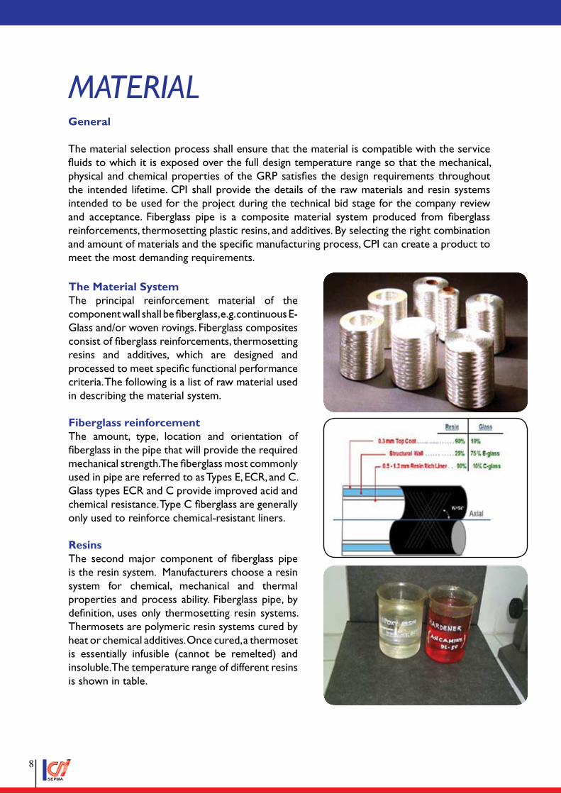
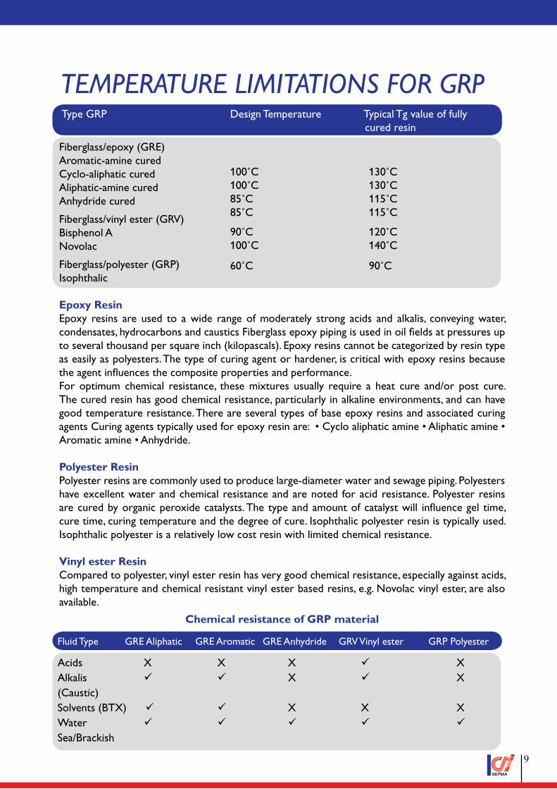
The Material SystemThe principal reinforcement material of the component wall shall be fiberglass, e.g. continuous E-Glass and/or woven rovings. Fiberglass composites consist of fiberglass reinforcements, thermosetting resins and additives, which are designed and processed to meet specific functional performance criteria. The following is a list of raw material used in describing the material system.
Fiberglass reinforcementThe amount, type, location and orientation of fiberglass in the pipe that will provide the required mechanical strength. The fiberglass most commonly used in pipe are referred to as Types E, ECR, and C. Glass types ECR and C provide improved acid and chemical resistance. Type C fiberglass are generally only used to reinforce chemical-resistant liners.
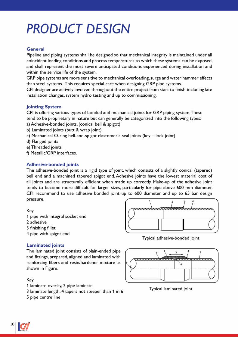
ResinsThe second major component of fiberglass pipe is the resin system. Manufacturers choose a resin system for chemical, mechanical and thermal properties and process ability. Fiberglass pipe, by definition, uses only thermosetting resin systems. Thermosets are polymeric resin systems cured by heat or chemical additives. Once cured, a thermoset is essentially infusible (cannot be remelted) and insoluble. The temperature range of different resins is shown in table.
�
Fiberglass/epoxy (GRE)Aromatic-amine cured Cyclo-aliphatic cured Aliphatic-amine curedAnhydride cured
Fiberglass/vinyl ester (GRV)Bisphenol ANovolac
Fiberglass/polyester (GRP)Isophthalic
Epoxy ResinEpoxy resins are used to a wide range of moderately strong acids and alkalis, conveying water, condensates, hydrocarbons and caustics Fiberglass epoxy piping is used in oil fields at pressures up to several thousand per square inch (kilopascals). Epoxy resins cannot be categorized by resin type as easily as polyesters. The type of curing agent or hardener, is critical with epoxy resins because the agent influences the composite properties and performance.For optimum chemical resistance, these mixtures usually require a heat cure and/or post cure. The cured resin has good chemical resistance, particularly in alkaline environments, and can have good temperature resistance. There are several types of base epoxy resins and associated curing agents Curing agents typically used for epoxy resin are: • Cyclo aliphatic amine • Aliphatic amine • Aromatic amine • Anhydride.
Polyester ResinPolyester resins are commonly used to produce large-diameter water and sewage piping. Polyesters have excellent water and chemical resistance and are noted for acid resistance. Polyester resins are cured by organic peroxide catalysts. The type and amount of catalyst will influence gel time, cure time, curing temperature and the degree of cure. Isophthalic polyester resin is typically used. Isophthalic polyester is a relatively low cost resin with limited chemical resistance.
Vinyl ester ResinCompared to polyester, vinyl ester resin has very good chemical resistance, especially against acids, high temperature and chemical resistant vinyl ester based resins, e.g. Novolac vinyl ester, are also available.
Chemical resistance of GRP material
100˚C100˚C85˚C85˚C
130˚C130˚C115˚C115˚C
90˚C100˚C
120˚C140˚C
60˚C 90˚C
Fluid Type GRE Aliphatic GRE Aromatic GRE Anhydride GRV Vinyl ester GRP Polyester
Acids X X X ¸ XAlkalis ¸ ¸ X ¸ X(Caustic)Solvents (BTX) ¸ ¸ X X XWater ¸ ¸ ¸ ¸ ¸Sea/Brackish
teMPerature lIMItatIons for GrPType GRP Design Temperature Typical Tg value of fully cured resin
�
Product desIGnGeneralPipeline and piping systems shall be designed so that mechanical integrity is maintained under all coincident loading conditions and process temperatures to which these systems can be exposed, and shall represent the most severe anticipated conditions experienced during installation and within the service life of the system.GRP pipe systems are more sensitive to mechanical overloading, surge and water hammer effects than steel systems. This requires special care when designing GRP pipe systems.CPI designer are actively involved throughout the entire project from start to finish, including late installation changes, system hydro testing and up to commissioning.
Jointing SystemCPI is offering various types of bonded and mechanical joints for GRP piping system. Thesetend to be proprietary in nature but can generally be categorized into the following types:a) Adhesive-bonded joints, (conical bell & spigot)b) Laminated joints (butt & wrap joint)c) Mechanical O-ring bell-and-spigot elastomeric seal joints (key – lock joint)d) Flanged jointse) Threaded jointsf) Metallic/GRP interfaces.
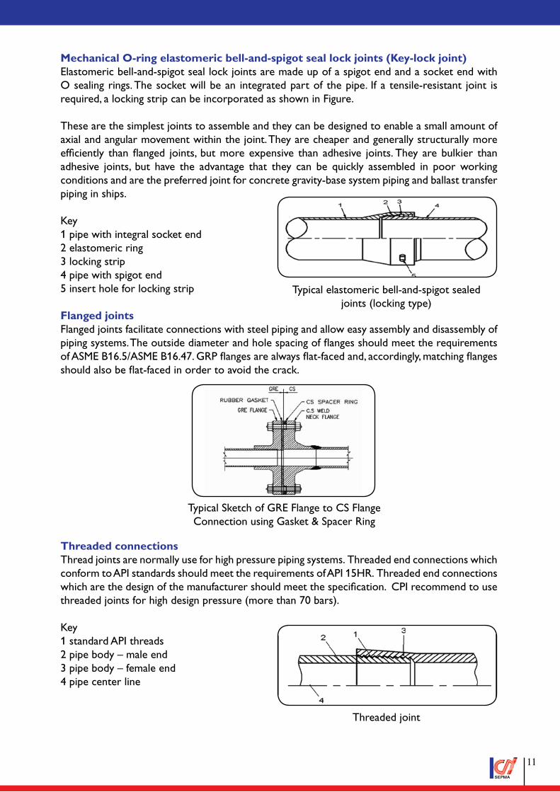
Adhesive-bonded jointsThe adhesive-bonded joint is a rigid type of joint, which consists of a slightly conical (tapered) bell end and a machined tapered spigot end. Adhesive joints have the lowest material cost of all joints and are structurally efficient when made up correctly. Make-up of the adhesive joint tends to become more difficult for larger sizes, particularly for pipe above 600 mm diameter. CPI recommend to use adhesive bonded joint up to 600 diameter and up to 65 bar design pressure.
Key1 pipe with integral socket end2 adhesive3 finishing fillet4 pipe with spigot end
Laminated jointsThe laminated joint consists of plain-ended pipe and fittings, prepared, aligned and laminated with reinforcing fibers and resin/hardener mixture as shown in Figure.
Key1 laminate overlay, 2 pipe laminate3 laminate length, 4 tapers not steeper than 1 in 65 pipe centre line
Typical adhesive-bonded joint
Typical laminated joint
�0
Mechanical O-ring elastomeric bell-and-spigot seal lock joints (Key-lock joint)Elastomeric bell-and-spigot seal lock joints are made up of a spigot end and a socket end with O sealing rings. The socket will be an integrated part of the pipe. If a tensile-resistant joint is required, a locking strip can be incorporated as shown in Figure.
These are the simplest joints to assemble and they can be designed to enable a small amount of axial and angular movement within the joint. They are cheaper and generally structurally more efficiently than flanged joints, but more expensive than adhesive joints. They are bulkier than adhesive joints, but have the advantage that they can be quickly assembled in poor working conditions and are the preferred joint for concrete gravity-base system piping and ballast transfer piping in ships.
Key1 pipe with integral socket end2 elastomeric ring3 locking strip4 pipe with spigot end5 insert hole for locking strip
Flanged jointsFlanged joints facilitate connections with steel piping and allow easy assembly and disassembly of piping systems. The outside diameter and hole spacing of flanges should meet the requirements of ASME B16.5/ASME B16.47. GRP flanges are always flat-faced and, accordingly, matching flanges should also be flat-faced in order to avoid the crack.
Threaded connectionsThread joints are normally use for high pressure piping systems. Threaded end connections which conform to API standards should meet the requirements of API 15HR. Threaded end connections which are the design of the manufacturer should meet the specification. CPI recommend to use threaded joints for high design pressure (more than 70 bars).
Key1 standard API threads2 pipe body – male end3 pipe body – female end4 pipe center line
Typical elastomeric bell-and-spigot sealed joints (locking type)
Typical Sketch of GRE Flange to CS Flange Connection using Gasket & Spacer Ring
Threaded joint
��
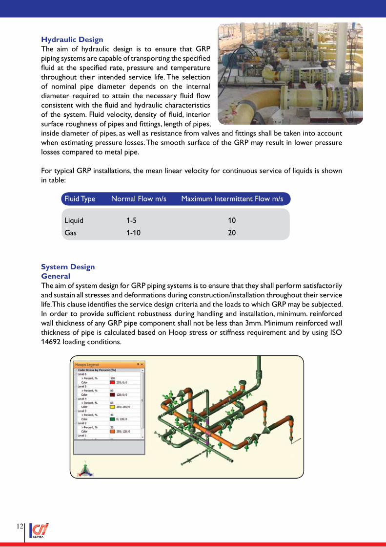
Hydraulic DesignThe aim of hydraulic design is to ensure that GRP piping systems are capable of transporting the specified fluid at the specified rate, pressure and temperature throughout their intended service life. The selection of nominal pipe diameter depends on the internal diameter required to attain the necessary fluid flow consistent with the fluid and hydraulic characteristics of the system. Fluid velocity, density of fluid, interior surface roughness of pipes and fittings, length of pipes, inside diameter of pipes, as well as resistance from valves and fittings shall be taken into account when estimating pressure losses. The smooth surface of the GRP may result in lower pressure losses compared to metal pipe.
For typical GRP installations, the mean linear velocity for continuous service of liquids is shown in table:
Fluid Type Normal Flow m/s Maximum Intermittent Flow m/s
Liquid 1-5 10
Gas 1-10 20
System DesignGeneralThe aim of system design for GRP piping systems is to ensure that they shall perform satisfactorily and sustain all stresses and deformations during construction/installation throughout their service life. This clause identifies the service design criteria and the loads to which GRP may be subjected. In order to provide sufficient robustness during handling and installation, minimum. reinforced wall thickness of any GRP pipe component shall not be less than 3mm. Minimum reinforced wall thickness of pipe is calculated based on Hoop stress or stiffness requirement and by using ISO 14692 loading conditions.
��
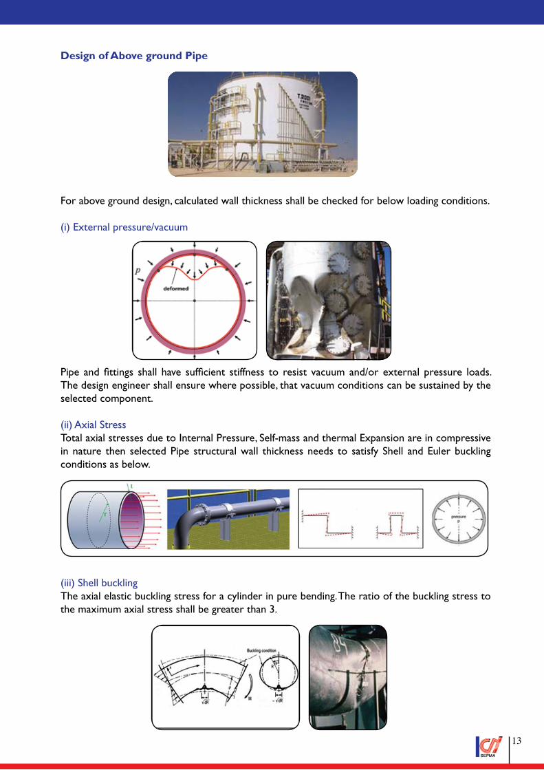
Design of Above ground Pipe
For above ground design, calculated wall thickness shall be checked for below loading conditions.
(i) External pressure/vacuum
Pipe and fittings shall have sufficient stiffness to resist vacuum and/or external pressure loads. The design engineer shall ensure where possible, that vacuum conditions can be sustained by the selected component.
(ii) Axial StressTotal axial stresses due to Internal Pressure, Self-mass and thermal Expansion are in compressive in nature then selected Pipe structural wall thickness needs to satisfy Shell and Euler buckling conditions as below.
(iii) Shell bucklingThe axial elastic buckling stress for a cylinder in pure bending. The ratio of the buckling stress to the maximum axial stress shall be greater than 3.
��
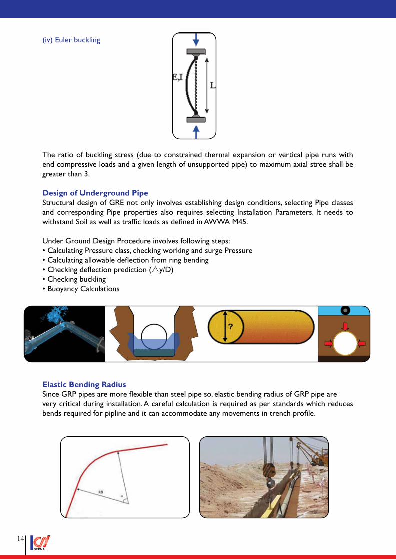
(iv) Euler buckling
The ratio of buckling stress (due to constrained thermal expansion or vertical pipe runs with end compressive loads and a given length of unsupported pipe) to maximum axial stree shall be greater than 3.
Design of Underground PipeStructural design of GRE not only involves establishing design conditions, selecting Pipe classes and corresponding Pipe properties also requires selecting Installation Parameters. It needs to withstand Soil as well as traffic loads as defined in AWWA M45.
Under Ground Design Procedure involves following steps:• Calculating Pressure class, checking working and surge Pressure• Calculating allowable deflection from ring bending• Checking deflection prediction (ry/D)• Checking buckling• Buoyancy Calculations
Elastic Bending RadiusSince GRP pipes are more flexible than steel pipe so, elastic bending radius of GRP pipe arevery critical during installation. A careful calculation is required as per standards which reduces bends required for pipline and it can accommodate any movements in trench profile.
��
Design EnvelopeWith Isotropic materials (properties of a material are identical in all direction) such as steel, the effect of combined stresses (pressure and non-pressure induced) are greatly simplified as hoop and axial strength are identical. This result gives a significant margin in allowable strength to accommodate this extra axial stress as the pressure induced. Axial stress (load) is exactly one half of hoop stress. Whereas, for anisotropic material (properties of a material are different in all direction) such as filament wound GRP pipes, hoop and axial strength are significantly different. Axial stress is not exactly half of hoop stress. Therefore hoop strength is significantly greater than the axial strength.
If the effective hoop and axial stresses, ợheff, and ợaeff, lie inside the factored long-term design envelope, then the GRP pipes and fittings designed within the acceptable limits. If the stresses lie outside this envelope, then high-rated GRP pipes and fittings, i.e. a thicker walled pipes and fittings shall be chosen and repeat the same stress calculation until it lies within the acceptable limits of factored long-term design envelope.
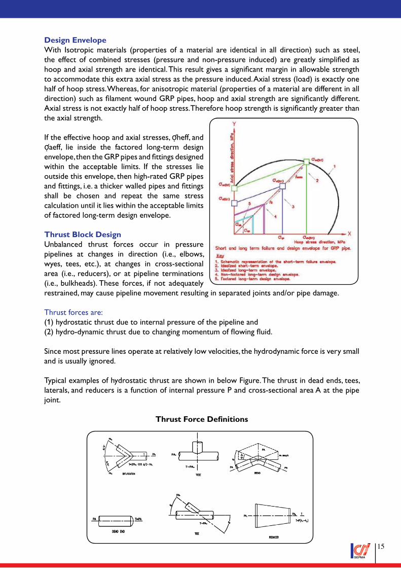
Thrust Block DesignUnbalanced thrust forces occur in pressure pipelines at changes in direction (i.e., elbows, wyes, tees, etc.), at changes in cross-sectional area (i.e., reducers), or at pipeline terminations (i.e., bulkheads). These forces, if not adequately restrained, may cause pipeline movement resulting in separated joints and/or pipe damage.
Thrust forces are: (1) hydrostatic thrust due to internal pressure of the pipeline and(2) hydro-dynamic thrust due to changing momentum of flowing fluid.
Since most pressure lines operate at relatively low velocities, the hydrodynamic force is very small and is usually ignored.
Typical examples of hydrostatic thrust are shown in below Figure. The thrust in dead ends, tees, laterals, and reducers is a function of internal pressure P and cross-sectional area A at the pipe joint.
Thrust Force Definitions
��
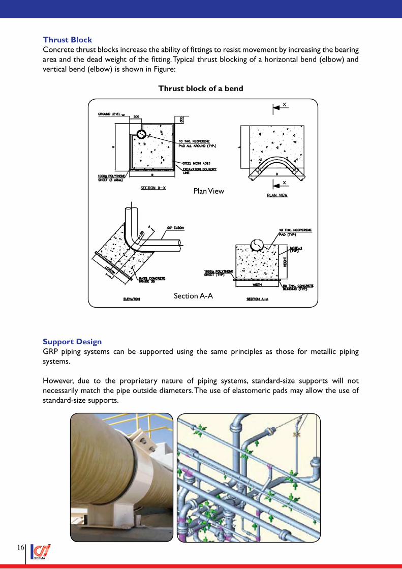
Thrust BlockConcrete thrust blocks increase the ability of fittings to resist movement by increasing the bearing area and the dead weight of the fitting. Typical thrust blocking of a horizontal bend (elbow) and vertical bend (elbow) is shown in Figure:
Thrust block of a bend
Support DesignGRP piping systems can be supported using the same principles as those for metallic piping systems.
However, due to the proprietary nature of piping systems, standard-size supports will not necessarily match the pipe outside diameters. The use of elastomeric pads may allow the use of standard-size supports.
Section A-A
Plan View
��
The following requirements and recommendations apply to the use of system supports.a) Supports shall be spaced to avoid sag (excessive displacement over time) and/or excessive vibration for the design life of the piping system.b) In all cases, support design should be in accordance with the CPI guidelines. CPI will provide the support design for above ground pipe system.c) Valves or other heavy attached equipment shall be independently supported.d) GRP piping should be adequately supported to ensure that the attachment of hoses at locations such as utility or loading stations does not result in the pipe being pulled in a manner that could overstress material.
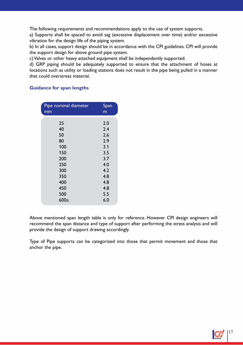
Guidance for span lengths
Pipe nominal diameter Span mm m
25 2.0 40 2.4 50 2.6 80 2.9 100 3.1 150 3.5 200 3.7 250 4.0 300 4.2 350 4.8 400 4.8 450 4.8 500 5.5 600≥ 6.0
Above mentioned span length table is only for reference. However CPI design engineers will recommend the span distance and type of support after performing the stress analysis and will provide the design of support drawing accordingly.
Type of Pipe supports can be categorized into those that permit movement and those that anchor the pipe.
��
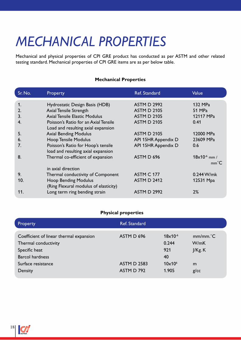
MechanIcal ProPertIesMechanical and physical properties of CPI GRE product has conducted as per ASTM and other related testing standard. Mechanical properties of CPI GRE items are as per below table.
Mechanical Properties
Physical properties
Sr. No. Property Ref. Standard Value
1. Hydrostatic Design Basis (HDB) ASTM D 2992 132 MPa2. Axial Tensile Strength ASTM D 2105 51 MPa3. Axial Tensile Elastic Modulus ASTM D 2105 12117 MPa4. Poisson’s Ratio for an Axial Tensile ASTM D 2105 0.41 Load and resulting axial expansion5. Axial Bending Modulus ASTM D 2105 12000 MPa6. Hoop Tensile Modulus API 15HR Appendix D 23609 MPa7. Poisson’s Ratio for Hoop’s tensile API 15HR Appendix D 0.6 load and resulting axial expansion8. Thermal co-efficient of expansion ASTM D 696 18x10-6 mm /
mm˚C in axial direction9. Thermal conductivity of Component ASTM C 177 0.244 W/mk 10. Hoop Bending Modulus ASTM D 2412 12531 Mpa (Ring Flexural modulus of elasticity)11. Long term ring bending strain ASTM D 2992 2%
Property Ref. Standard
Coefficient of linear thermal expansion ASTM D 696 18x10-6 mm/mm.˚CThermal conductivity 0.244 W/mKSpecific heat 921 J/Kg. KBarcol hardness 40Surface resistance ASTM D 2583 10x106 mDensity ASTM D 792 1.905 g/cc
��
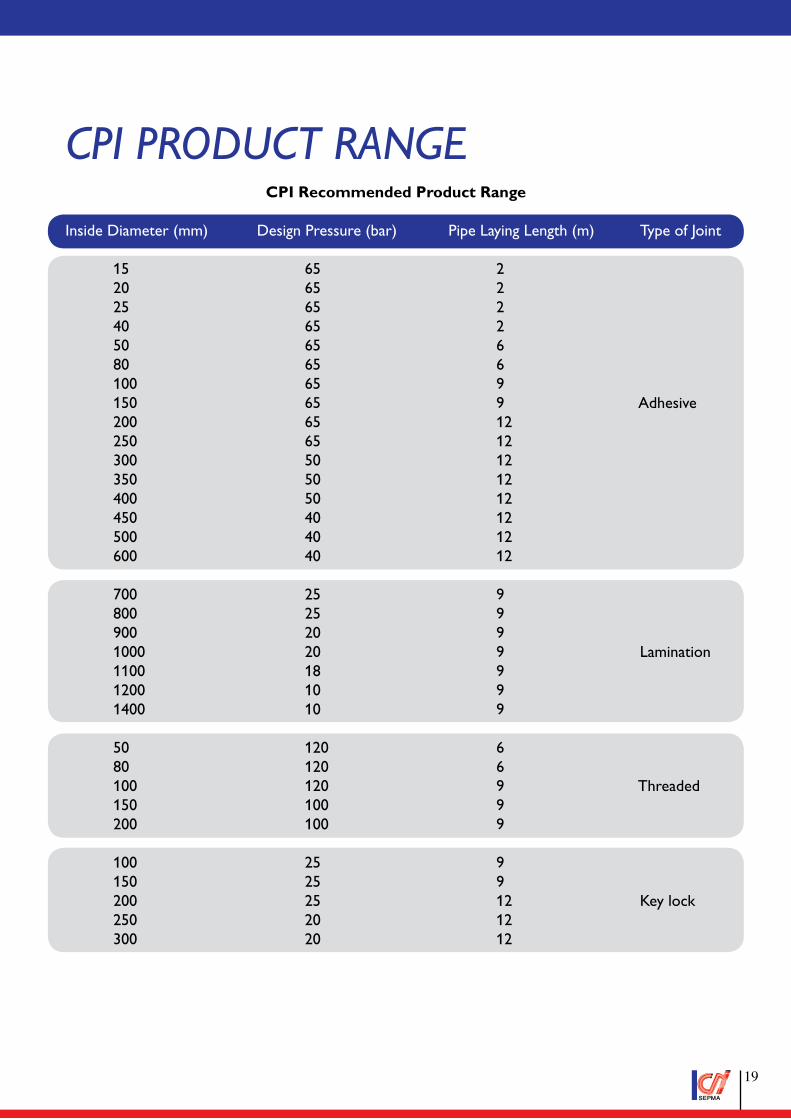
cPI Product ranGeCPI Recommended Product Range
Inside Diameter (mm) Design Pressure (bar) Pipe Laying Length (m) Type of Joint
15 65 2 20 65 2 25 65 2 40 65 2 50 65 6 80 65 6 100 65 9 150 65 9 Adhesive 200 65 12 250 65 12 300 50 12 350 50 12 400 50 12 450 40 12 500 40 12 600 40 12 700 25 9 800 25 9 900 20 9 1000 20 9 Lamination 1100 18 9 1200 10 9 1400 10 9 50 120 6 80 120 6 100 120 9 Threaded 150 100 9 200 100 9 100 25 9 150 25 9 200 25 12 Key lock 250 20 12 300 20 12
��

Notes
�0
www.cpioman.com44 Years Experience
Head Office : P.Box 495, P.C. 131, Hamriya, Sultanate of OmanTel +968 24568202/3/4 +968 22008888 Fax +968 24568208 +968 22006666
Email: [email protected] [email protected]
Factory : Road No 9, P.O.Box 327, Sohar Industrial EstateSohar, Sultanate of Oman
Tel +968 26751992/3/4 Fax +968 26751996Email: [email protected]
15LR-0030 & 15HR-0031Refer to official listing on FM Web
Follow us on:
LEA
DER
S IN
MA
NU
FAC
TU
RIN
G F
IBER
GLA
SS P
IPES
ww
w.c
pio
man
.co
m