test plan template - rochester institute of...
TRANSCRIPT

Document Revision No.: 2 Revised: 05/07/23 RIT KGCOE MSD Program
P10505 Low Energy Printing - Cold Pressure Fusing 2Test Plans & Test Results
By: Aniket Arora, David Hatch, Eric Wilcox, Jon Burville, and Thomas Stojanov
Table of contents
1. MSD I: PRELIMINARY TEST PLAN............................................................31.1. Introduction and Overview.............................................................................................................3
1.2. Systems and Critical Components being tested.............................................................................4
1.3. Approval: Team, Guide, Technical TA, Customer/Sponsor........................................................6
1.4. Test Strategy.....................................................................................................................................7
1.5. Definitions: Important Terminology............................................................................................10
2. MSD II: FINAL TEST PLAN........................................................................122.1. Introduction....................................................................................................................................12
2.2. Test Structure, Sampling Techniques/Safety and Problem Reporting.....................................13
2.3. Measurement Capability, Equipment, Configuration................................................................16
2.4. Test Conditions, Setup Instructions.............................................................................................19
2.5. Sponsor/Customer, Site Related, Requests..................................................................................21
2.6. DOE Test Matrix............................................................................................................................23
2.7. Assumptions....................................................................................................................................23
MSD II – WKS 3-10 DESIGN TEST VERIFICATION..........................................242.8. Test Results.....................................................................................................................................24
2.9. Logistics and Documentation........................................................................................................24
2.10. Definition of a Successful Test, Pass / Fail Criteria....................................................................24
2.11. Contingencies/ Mitigation for Preliminary or Insufficient Results...........................................24
2.12. Analysis of Data – Design Summary............................................................................................24
2.13. Conclusion or Design Summary....................................................................................................24
2.14. Function/ Performance Reviews...................................................................................................24
2.15. References.......................................................................................................................................24
2.16. Appendices......................................................................................................................................25
RIT KGCOE MSD Program Page 1 Revision:

Document Revision No.: 2 Revised: 05/07/23 RIT KGCOE MSD Program
P10505 Low Energy Printing - Cold Pressure Fusing 2Test Plans & Test Results
1. MSD I: PRELIMINARY TEST PLAN
1.1. Introduction and OverviewProject Purpose
The purpose of this year’s project is to design and test a fixture that is able to uniformly
fuse toner on the paper solely based on pressure instead of heat. This technology is
expected to reduce the overall energy consumed in the printing process.
Project Background
This project is the second part of the Cold Pressure Fusing project at Xerox. The project
last year (P09505) was focused at designing a text fixture that was capable of fusing
toner with high pressure instead of heat. This year’s project (P10505) is focused mainly
at optimizing the design from last year and testing the design under various
configurations.
Project Summary (provided by Xerox)
It is broadly recognized that xerographic digital printers are quite energy intensive and
as customers become more and more environmentally conscious they are demanding
improvements. The ability to be more energy efficient is not just the "green" thing to do;
it is increasingly becoming a significant competitive advantage. In addition, all print
engine providers, Xerox, HP, Ricoh, Samsung, Lexmark, Kodak, etc. strive to meet
more and more stringent Energy Star and other certification requirements. While print
engine providers have considerably reduced the power required to print at a given
process speed over the last decade, there still is opportunity and a need to further
reduce printer power. A large share of any xerographic printer power is consumed by
the fusing sub-system: where toner is heated well above its melting point, so as to
enable heat flow, coalescence and paper adhesion. Improved low energy fusing is the
target for this project.
RIT KGCOE MSD Program Page 2 Revision:

Document Revision No.: 2 Revised: 05/07/23 RIT KGCOE MSD Program
Project testing plan
The testing for this project will encompass a full factorial DOE with 5 factors: skew
angle, load, compliance, paper orientation and paper weight. The output data from the
experiment will include the percentage of fusing and uniformity as metrics. These
outputs will be measured using the Smudge test (described later).
1.2. Systems and Critical Components being tested
The system level diagram consists of five input variables:
1. Paper Orientation – This is the direction the paper is fed into the fuser. This
factor has 2 levels: Landscape and Portrait. These levels affect the overall
print quality as the forces acting on the main rollers will change according to
the length of the paper in contact with the rollers. It is expected that the
RIT KGCOE MSD Program Page 3 Revision:
Figure 1: System level design (block diagram)

Document Revision No.: 2 Revised: 05/07/23 RIT KGCOE MSD Program
portrait configuration will cause a lower deflection as compared to the
Landscape configuration.
2. Paper Weight – The system needs to accommodate for different paper
weights. The paper weight factor has two levels: 20lb and 24 lb. The weight
of the paper in the system affects the overall paper thickness that goes
through the system. This thickness would affect the amount of load that is
exerted on the main rollers. It is assumed that the 24lb paper would exert
higher loads on the system because of greater thickness. To accommodate
for these load changes, the system is designed with compliance that can
adjust the load on the rollers.
3. Skew Angle – The system needs to be able to adjust to a minimum of three
different skew angles: 1.4°, 1.9° and 2.4°. These skew angles are defined as
the angle between the top main roller and the support rollers. The skew
angles concentrate the force of the support rollers towards the center of the
main top roller and hence help in reducing its deflection.
4. Compliance – The compliance in the system is required for adjusting to two
different paper weights. It is tested under two levels: Low and High. These
levels are important to decide the optimum level of compliance that would be
required for the system to adjust for the different paper weights. The
compliance also absorbs the ‘shock’ that the system undergoes as soon as
the paper enters the rollers.
5. Pressure/Load – The pressure or load is applied on the system at 4 points,
two on each side of the roller. The amount of load on the system can vary
from 50lbs – 150lbs for each of the four points. The load is measured by
Load Cells present on all four points and a signal conditioner will be used to
amplify the signal so that it is easily read in the DAQ system. The system is
analyzed under 2 different load conditions: 50lbs and 150lbs of weight on the
load points. These levels will help in the analysis of an optimum level for load
on the system.
RIT KGCOE MSD Program Page 4 Revision:

Document Revision No.: 2 Revised: 05/07/23 RIT KGCOE MSD Program
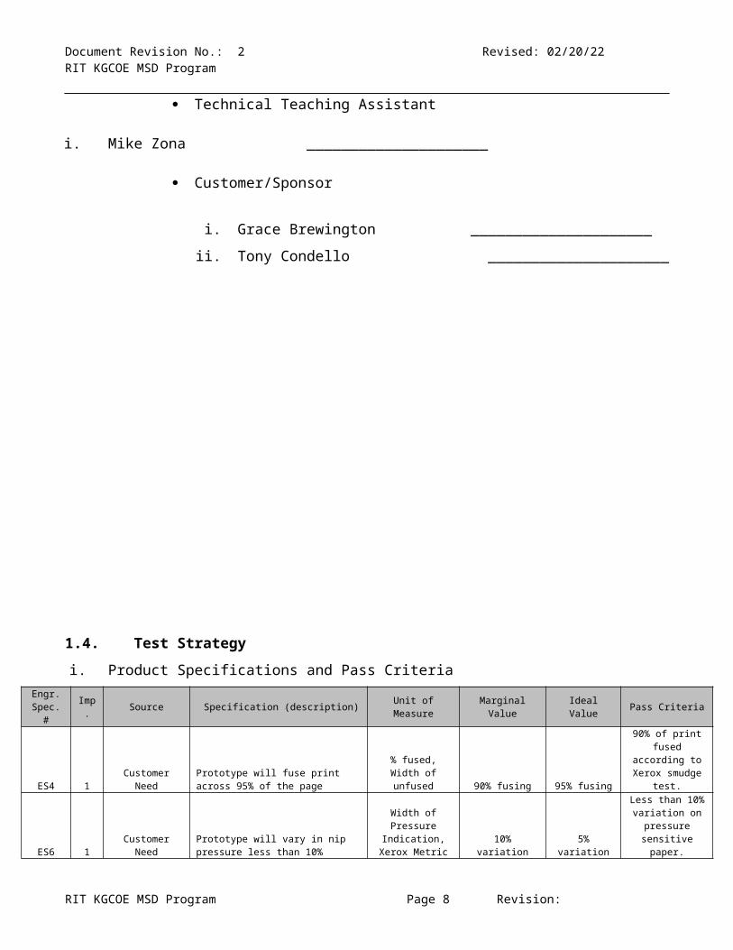
1.3. Approval: Team, Guide, Technical TA, Customer/SponsorApproved by:
Team Members
i. Aniket Arora _____________________
ii. David Hatch _____________________
iii. Eric Wilcox _____________________
iv. Jon Burville _____________________
v. Thomas Stojanov _____________________
Guide i. Bill Nowak _____________________
Technical Teaching Assistant
i. Mike Zona _____________________
Customer/Sponsor
i. Grace Brewington _____________________
ii. Tony Condello _____________________
RIT KGCOE MSD Program Page 5 Revision:

Document Revision No.: 2 Revised: 05/07/23 RIT KGCOE MSD Program
1.4. Test Strategyi. Product Specifications and Pass Criteria
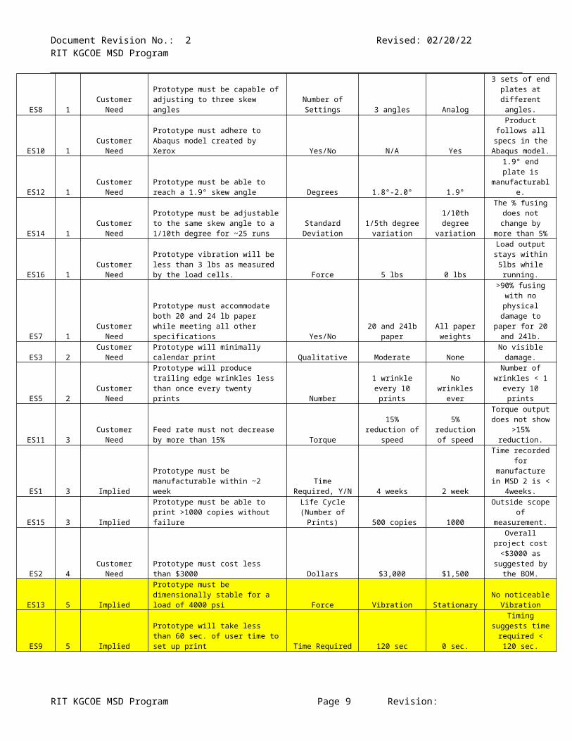
Engr. Spec. # Imp. Source Specification (description) Unit of Measure Marginal Value Ideal Value Pass Criteria
ES4 1 Customer NeedPrototype will fuse print across 95% of the page
% fused, Width of unfused 90% fusing 95% fusing
90% of print fused according to
Xerox smudge test.
ES6 1 Customer NeedPrototype will vary in nip pressure less than 10%
Width of Pressure Indication, Xerox
Metric 10% variation 5% variation
Less than 10% variation on
pressure sensitive paper.
ES8 1 Customer NeedPrototype must be capable of adjusting to three skew angles
Number of Settings 3 angles Analog
3 sets of end plates at different
angles.
ES10 1 Customer NeedPrototype must adhere to Abaqus model created by Xerox Yes/No N/A Yes
Product follows all specs in the
Abaqus model.
ES12 1 Customer NeedPrototype must be able to reach a 1.9° skew angle Degrees 1.8°-2.0° 1.9°
1.9° end plate is manufacturable.
ES14 1 Customer Need
Prototype must be adjustable to the same skew angle to a 1/10th degree for ~25 runs
Standard Deviation
1/5th degree variation
1/10th degree variation
The % fusing does not change by more than 5%
ES16 1 Customer NeedPrototype vibration will be less than 3 lbs as measured by the load cells. Force 5 lbs 0 lbs
Load output stays within 5lbs while
running.
ES7 1 Customer Need
Prototype must accommodate both 20 and 24 lb paper while meeting all other specifications Yes/No
20 and 24lb paper
All paper weights
>90% fusing with no physical
damage to paper for 20 and 24lb.
ES3 2 Customer Need Prototype will minimally calendar print Qualitative Moderate NoneNo visible damage.
ES5 2 Customer Need
Prototype will produce trailing edge wrinkles less than once every twenty prints Number
1 wrinkle every 10 prints
No wrinkles ever
Number of wrinkles < 1 every
10 prints
ES11 3 Customer NeedFeed rate must not decrease by more than 15% Torque
15% reduction of speed
5% reduction of speed
Torque output does not show
>15% reduction.
ES1 3 ImpliedPrototype must be manufacturable within ~2 week
Time Required, Y/N 4 weeks 2 week
Time recorded for manufacture in
MSD 2 is < 4weeks.
ES15 3 ImpliedPrototype must be able to print >1000 copies without failure
Life Cycle (Number of Prints) 500 copies 1000
Outside scope of measurement.
ES2 4 Customer Need Prototype must cost less than $3000 Dollars $3,000 $1,500
Overall project cost <$3000 as
suggested by the BOM.
ES13 5 ImpliedPrototype must be dimensionally stable for a load of 4000 psi Force Vibration Stationary
No noticeable Vibration
ES9 5 ImpliedPrototype will take less than 60 sec. of user time to set up print Time Required 120 sec 0 sec.
Timing suggests time required <
120 sec.
Table 1: Engineering Specifications (Importance Scale, 1-Highest, 5-Lowest)
RIT KGCOE MSD Program Page 6 Revision:

Document Revision No.: 2 Revised: 05/07/23 RIT KGCOE MSD Program
a. Test Equipment available
DAQ
1 Signal Conditioner
Motor
Power Supply
4 Load cells
Wires
P09505 Fixture
Pressure Sensitive Paper
Kill Switches
b. Test Equipment needed but not available
CPU
3 Signal Conditioners
Multi-meter
Tachometer
Dynamometer
Additionally, See BOM
ii. Phases of Testing
1.4.1.1. Component/ Device
1. Load Cells: The load cells provided to the group need to be tested to
check for load range compatibility and output voltage consistency.
2. Compliance washers: The compliance washers need to be tested for
spring factor (k) that is listed on the manufacturing specifications. The
spring factor for the washers (springs) can change overtime because of
repeated use or excessive force (fatigue).
3. Rollers: The rollers need to be checked for concentricity before they are
used for the project. They also need to be checked at pre-assigned
intervals between test runs.
4. Skew Angle: The skew angle needs to be checked for accuracy before
and during the course of the runs.
RIT KGCOE MSD Program Page 7 Revision:
Document Revision No.: 2 Revised: 05/07/23 RIT KGCOE MSD Program
1.4.1.2. Subsystem
1. DAQ system: The DAQ system can be checked periodically by running
the load cells under known loads and checking for output in the VI. This
would ensure that the system is operating under the initial configuration.
The loads can be applied using the UTM and the outputs can be
compared to the expected output from the mathematical model.
2. Fusing System: The fusing system needs to be checked for:
I. Permanent roller deflection: This can be periodically checked by
inspection with a Micrometer.
II. Concentricity: This can be periodically checked by inspection with a
Micrometer.
III. Bearings Rotation: Deviations in the torque output could suggest
issues with the bearings. The bearings can be tested using a simple
torque experiment. In this experiment, the bearings are subjected to
a constant torque and the number of rotations it achieves before
coming to rest is used as the output. This output can be compared
over time to see the issues.
3. Safety System: The ‘kill switch’ can be tested periodically to ensure that
performs as expected.
1.4.1.3. Integration
1. Hardware: The machined part can be checked against the system
schematics to verify that the dimensions are within tolerance. This can
be done with the help of a micrometer. The critical areas of testing would
be:
a. Outside diameter of bearing vs. housing diameter.
b. Dimensions that affect the skew angle.
c. Inner diameter of the bearing vs. shaft diameter.
RIT KGCOE MSD Program Page 8 Revision:
Document Revision No.: 2 Revised: 05/07/23 RIT KGCOE MSD Program
d. Diameter of rollers.
2. Software: The outputs can be checked against a known load to check
against expected response. Critical areas of testing could be:
I. Load cells
II. Torque output
III. Kill Switches
IV. Signal Conditioners
The wiring of the prototype must be checked against electrical schematics.
1.4.1.4. Reliability
The system can be periodically checked for wear in the following ways:
a. Roller deflection: As discussed in section 1.4.1.3.2.a
b. Concentricity: As discussed in section 1.4.1.3.2.b
c. Bearings issues: As discussed before 1.4.1.3.2.c
d. Compliance: As discussed in section 1.4.1.2.2
1.4.1.5. Customer Satisfaction
Show the customer the final optimized product and run the system under
randomized settings.
1.5. Definitions: Important Terminology
1.5.1. Skew Angle: The skew angle is the angle between the Main Roller and the
support rollers. It is designed in order to focus the pressure towards the
centre of the main roller.
1.5.2. Compliance: The compliance for the system is the ability for the system to
adjust to the variation in the load. This is achieved by the use of compliance
RIT KGCOE MSD Program Page 9 Revision:
1.9 degrees
Main Roller
Support Roller

Document Revision No.: 2 Revised: 05/07/23 RIT KGCOE MSD Program
washers or springs with a specified spring constant. Compliance is
understood to be the inverse function of spring constant of the compliant
material.
1.5.3. Calendaring: The change in the thickness of the paper (deformation) due to
pressures exceeding its yield strength.
1.5.4. Nip Width: This is the area of contact between the fusing rollers due to
application of load.
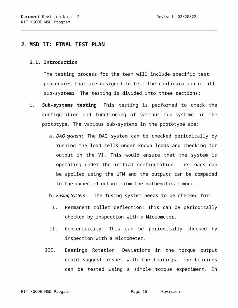
2. MSD II: FINAL TEST PLAN
2.1. Introduction
The testing process for the team will include specific test procedures that are
designed to test the configuration of all sub-systems. The testing is divided into
three sections:
i. Sub-systems testing: This testing is performed to check the configuration and
functioning of various sub-systems in the prototype. The various sub-systems in the
prototype are:
a. DAQ system: The DAQ system can be checked periodically by running the
load cells under known loads and checking for output in the VI. This would
ensure that the system is operating under the initial configuration. The loads
can be applied using the UTM and the outputs can be compared to the
expected output from the mathematical model.
RIT KGCOE MSD Program Page 10 Revision:

Document Revision No.: 2 Revised: 05/07/23 RIT KGCOE MSD Program
b. Fusing System: The fusing system needs to be checked for:
I. Permanent roller deflection: This can be periodically checked by
inspection with a Micrometer.
II. Concentricity: This can be periodically checked by inspection with a
Micrometer.
III. Bearings Rotation: Deviations in the torque output could suggest issues
with the bearings. The bearings can be tested using a simple torque
experiment. In this experiment, the bearings are subjected to a constant
torque and the number of rotations it achieves before coming to rest is
used as the output. This output can be compared over time to see the
issues.
c. Safety System: The ‘kill switch’ can be tested periodically to ensure that it
performs as expected.
ii. Initial testing: This set of test procedures are used to define and understand the
scope of the final product testing. This stage of testing requires a small number of
tests under specific conditions (1/4th factorial design). The expected results from this
test include: prototype functioning, timing studies (setup, data acquisition and data
processing), types of output achieved, feasibility of concept etc. These test results
are analyzed and the used to determine the testing procedures for the Final testing
phase.
iii. Final testing: This is the main set of test procedures that are performed on the
prototype. These test procedures check and confirm the effects of the four factors
(skew angle, load, compliance and paper orientation) on the uniformity of the
pressure across the nip. The tests are performed under 24 different test conditions
(full factorial design) on medium or high grade pressure sensitive paper. The testing
is then extended to the check the effects of the four factors on the fusing of the print
on the paper. In this phase, only the factors with a co-relation with uniformity are
varied and tested on unfused printed paper. The results from the two tests are then
analyzed to determine the set of optimal settings that would achieve a uniform print
RIT KGCOE MSD Program Page 11 Revision:

Document Revision No.: 2 Revised: 05/07/23 RIT KGCOE MSD Program
across the paper. These settings are then used to manufacture and assemble a final
working prototype.
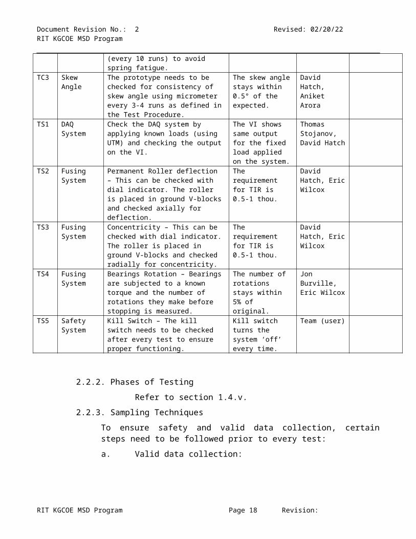
2.2. Test Structure, Sampling Techniques/Safety and Problem Reporting2.2.1. Test Structure, Work Breakdown Structure
Test #
System Component
Details Pass criteria Person in charge
Due Date
TI1 Hardware The machined part needs to be checked against the system schematics to verify that the dimensions are in tolerance. Refer to section 1.4.1.3.
The critical dimensions are within tolerance indicated by the drawings
David Hatch, Eric Wilcox
TI2 System Wiring
The system wiring needs to be checked against the electrical schematics to ensure consistency.
The system absolutely follows the electrical schematics.
Thomas Stojanov, Jon Burville
TC1 Load cells The load cells are checked for compatibility of load range and consistency of output voltage by placing under the UTM at fixed load for 3 iterations and checking for output on the VI.
Load cells show consistent outputs (within 5% deviation of Voltage from the mean) for the test.
Thomas Stojanov, Aniket Arora
TC2 Compliance Washers
The compliance washers are checked for spring factor (k) by placing under specific loads and measuring the displacement. This needs to be done periodically (every 10 runs) to avoid spring fatigue.
The deviation stays within 5% of the original.
David Hatch, Aniket Arora
TC3 Skew Angle The prototype needs to be checked for consistency of skew angle using micrometer every 3-4 runs as defined in the Test Procedure.
The skew angle stays within 0.5° of the expected.
David Hatch, Aniket Arora
TS1 DAQ System
Check the DAQ system by applying known loads (using UTM) and checking the output on the VI.
The VI shows same output for the fixed load applied on the system.
Thomas Stojanov, David Hatch
TS2 Fusing System
Permanent Roller deflection – This can be checked with dial indicator. The roller is placed in ground V-blocks and checked axially for deflection.
The requirement for TIR is 0.5-1 thou.
David Hatch, Eric Wilcox
TS3 Fusing System
Concentricity – This can be checked with dial indicator. The roller is placed in ground V-blocks and checked radially for concentricity.
The requirement for TIR is 0.5-1 thou.
David Hatch, Eric Wilcox
TS4 Fusing System
Bearings Rotation – Bearings are subjected to a known torque and the number of rotations they make before stopping is measured.
The number of rotations stays within 5% of original.
Jon Burville, Eric Wilcox
TS5 Safety Kill Switch – The kill switch needs to Kill switch turns the Team (user)
RIT KGCOE MSD Program Page 12 Revision:

Document Revision No.: 2 Revised: 05/07/23 RIT KGCOE MSD Program
System be checked after every test to ensure proper functioning.
system ‘off’ every time.
2.2.2. Phases of Testing
Refer to section 1.4.v.
2.2.3. Sampling Techniques
To ensure safety and valid data collection, certain steps need to be followed prior to every test:
a. Valid data collection:
i. Check the electrical connections with the electrical schematics.ii. Check and ensure that all the mechanical components are secured
tightly in place (for e.g. screws and bolts are fastened).iii. Check the DAQ’s and the LabVIEW VI to ensure that the configuration
for the test match the Text Matrix.
b. Safetyi. Check the Emergency STOP button for proper functioning by turning
the system ON and OFF with the emergency STOP prior to every test.ii. Always perform the tests with a partner to ensure safety in case of an
accident.iii. Avoid wearing loose clothing or a tie while operating the device. Use a
tie pin if necessary.
2.2.4. Reporting Problems; Corrective Action
Any problems that arise during the course of data collection and equipment configuration must be recorded and reported to the group in the following format.
S.No Date/Time
Test # (from Test
Structure table)
Configuration #
(from test matrix)
Team members present
Problem description
Reasons (if known)
Suggestions/ actions taken
Problem Fixed (Yes/No/Pending)
e.g. 3/14/2010, 6:30 PM TS5 4
Aniket Arora,
Thomas Stojanov
The kill switch does not turn the motor
OFF.Loose wiring
Rechecked wiring with schematics and
rewired the connection
Yes
1
2
RIT KGCOE MSD Program Page 13 Revision:

Document Revision No.: 2 Revised: 05/07/23 RIT KGCOE MSD Program
3
4
5
6
7
8
2.3. Measurement Capability, Equipment, Configuration2.3.1. DAQ
DAQ Configuration
The Data Acquisition System (DAQ), however an advanced system, will
require slight user configuration for safe and proper use. A white and black
control panel, complete with real- time load cell readouts/ signal conditioners
for each of the four load cells and an emergency stop button, is provided with
the DAQ. Also provided is an analog motor controller which is capable of
controller motor status, direction, speed and torque. The test fixture will
accompany load cells which will provide the fastener load values. In addition
to the above devices a National Instruments (NI) Input/ Output (I/O) block will
be provided from which the above devices will indirectly interface to the
Personal Computer (PC).
RIT KGCOE MSD Program Page 14 Revision:
Document Revision No.: 2 Revised: 05/07/23 RIT KGCOE MSD Program
The emergency stop button is located in the center of the DAQ control panel
evident by its bright red color. The emergency stop will allow for proper DAQ
operation when in the default mode and will shut power off to the DAQ when
engaged. Default mode is defined as when the button is in the full out
position while engaged mode is defined as when the button is in the pressed
in position.
Each of the load cell readouts/ signal conditioners will be configured prior to
powering on the DAQ system. No user interface shall be required for any of
the readouts. Should any erroneous action occur with respect to the load
cell readouts/ signal conditioners refer to the Transducer Techniques DPM-3
manual provided with the DAQ system.
The analog motor controller allows for the user to potentially the inputs to the
DAQ system as testing allows. The rightmost button, marked as power, is
the main power to the motor controller assembly. This should remain on at
all times. Two direction buttons exist in the middle. The direction buttons
must remain in the forward direction at all times for testing. The reverse
direction may be utilized to clear paper jams. The speed and torque may be
alternated for calibration or as the user requires. The torque dial must
remain at the “max” position whereas the speed must be adjusted to 583.7
RPM which should be verified real- time through the LabView interface.
The load cells shall not require any user interface other than torquing the test
fixture fasteners to the desired load. While the DAQ is operating the user
can utilize the real- time readout of the load cell readouts/ signal conditioners
to properly load the test fixture fasteners to the desired loads. This will also
be available to the user in the LabView interface and shall read the same
values as the real- time readouts.
The NI I/O block is fixed and does not require any user interface. Any
interaction with the I/O block should be performed by a trained professional
or person(s) familiar with National Instruments and LabView data interfaces.
RIT KGCOE MSD Program Page 15 Revision:

Document Revision No.: 2 Revised: 05/07/23 RIT KGCOE MSD Program
Limitations of DAQ
The DAQ has few limitations as they are solely based on the measurement
capabilities of its components. The motor controller’s outputs or status can
be minimized or maximized to any point without damaging or adversely
altering the DAQ. The load cells are capable of handling up to 500lbs. of
force each which if exceeded may damage the load cells thus possibly
requiring replacement.
Outputs in LabView Interface
LabView is the primary point of data output and user interface for the DAQ
system. The motor can be electronically started and stopped through
software via a set of soft start and stop buttons. Motor speed in RPM and
torque in ft- lbs. is provided in both real- time and graphical formats with
respect to time. Horsepower is also calculated in real- time and graphical
formats with respect to time. The real- time output of each loadcell in lbs. will
also be given.
Load Cell Calibration
Load cell calibration is accomplished prior to testing with the test fixture.
Each load cell is tested in a calibrated hydraulic press with real- time output,
under which the load cells shall be measured for impedance at maximum
allowable load and shall be done at several points throughout its range. This
will be recorded as required. Thereby a calibration model can be obtained
for the load cells and applied to the LabView interface for the sake of load
correction.
Speed Output Calibration
Speed output calibration is also accomplished prior to testing with the test
fixture. Several speeds will be measured and recorded via the output shaft of
the motor through the use of a mechanical tachometer. Thereby a
calibration model can be obtained for the speed output and applied to the
LabView interface for the sake of speed correction.
RIT KGCOE MSD Program Page 16 Revision:

Document Revision No.: 2 Revised: 05/07/23 RIT KGCOE MSD Program
Torque Output Calibration
Torque output calibration is again accomplished prior to testing with the test
fixture. Several weights of known masses shall be hung from a specific
diameter pulley at a given speed under which typical equations of motion
shall be utilized to gather torque values for given output voltages of the
torque output. These values will be recorded. Thereby a calibration model
can be obtained for the torque output and applied to the LabView interface
for the sake of torque correction.
2.3.2. Torque measurement for Bearings – The torque measurement to check
the performance of the bearings follows a simple testing procedure. The
roller with the bearings is subjected to a fixed torque by wrapping a thread
with a fixed weight attached to one end of the string. This weight is dropped
from fixed height and the number of revolutions the rollers make before
coming to a stop is counted. These revolutions can be counted with either by
naked eye or with a camera.
2.3.3. Micrometer for skew angle measurement – The skew angle can be
measured with a micrometer by measuring the gap between the ends of the
skewed rollers. The gap can then be plugged in to the trigonometric function:
sin−1( PH
)=θ
Where P = (0.5 * Gap) between the ends of the skewed rollers and H is the
Length of the skewed rollers.
2.3.4. UTM – The Universal Testing Machine (UTM) can exert fixed amounts of
forces on the load cells. This fixed force can then be compared to the outputs
on the multi-meter to check the increase in voltage. This measurement can
then be checked for 2 different loads. This would give a good idea of how the
outputs from the load cells compare with the load exerted on them.
RIT KGCOE MSD Program Page 17 Revision:
Document Revision No.: 2 Revised: 05/07/23 RIT KGCOE MSD Program
2.4. Test Conditions, Setup Instructions2.4.1. Test Conditions
The test conditions for the testing procedure should remain fairly consistent
throughout the sampling and testing process. For the same reason testing is
to be performed in RIT, College of Engineering (4th floor, Design Center).
This would work best for controlling the temperatures and the humidity
factors for the current scope of the project.
As far as equipment verification and tests are considered, it is recommended
to use the same machine for each process throughout the entire length of the
project. For the machining process, it is recommended to use the same
machines and tools for the most part (might not be possible in some cases).
This will also reduce the variability in the testing process.
2.4.2. Setup Conditions and Procedure
The setup conditions for the prototype should remain fairly consistent
throughout the course of the project. After loading the rollers, it is necessary
to check the spacing between the main rollers. It has been observed during
the test runs that sometimes after loading the device, a small gap exists
between the main rollers on the P09505 prototype.
The setup procedure for the tests is:
1. Get the setup conditions from the test matrix.
2. If the skew angle stays the same go to step 9 or else go to step 3.
3. Take the main bolts out from the motor assembly. These bolts hold
the motor to the base. The motor should slide out of the assembly.
4. Unscrew the side bolts on the roller assembly. These bolts attach the
L-brackets that hold the roller assembly to the base. The roller
assembly should now be free and easy to take out.
5. Take the main bolts out off the roller assembly. These bolts go into
the end plates and hold the rollers in place.
RIT KGCOE MSD Program Page 18 Revision:

Document Revision No.: 2 Revised: 05/07/23 RIT KGCOE MSD Program
6. The end plates can now be swapped with the new set for the required
angle.
7. After assembling the end plates, rebuild the system. Check the
assembly of the system with the assembly schematics.
8. Connect the load cells to the DAQ and configure the load cells if
necessary. The load cells need to stay ON for 15 minutes
(startup/warm up time).
9. Check the wiring of the prototype with the Wiring Schematic.
10.For test number U1, U4, U7, U9, U12, U15, U17, U20 and U23, the
skew angle needs to be checked with a micrometer for consistency
(refer to section 2.2.1 – TC1).
11.For test number U1, U4, U7, U10, U13, U16, U19 and U22, the load
cells need to be checked with the UTM (refer to section 2.2.1 – TC1).
12.For test number U1, U11 and U21, the compliance washers need to
be tested under specific known load for deflection (refer to section
2.2.1 – TC2).
13.Load the system to the amount specified in the test matrix. It is a good
practice to wait for 30-60 seconds and check the output on the VI after
loading the system. It is observed that the compliance material tends
to dampen the load once it is exerted initially. This load slowly
steadies out and needs to be rechecked and reconfigured.
14.After the system is loaded, check the system by dry-running it and
stopping it with the Kill Switch. Observe any unnecessary vibrations or
noises that may arise. If any, record them in section 2.2.4.
15.Only if everything works well, insert a sheet of pressure sensitive
paper (or unfused paper) according to the angle orientation from the
test matrix.
RIT KGCOE MSD Program Page 19 Revision:

Document Revision No.: 2 Revised: 05/07/23 RIT KGCOE MSD Program
16.CAUTION: The device tends to pull the paper in the system very fast
(watch out for your fingers).
17.Collect the print of the other side of the device and mark the print with
Test Date, Time, Test number (from the Design Matrix) and team
members present.
18.Save the print in the group folder and unload the device.
2.5. Sponsor/Customer, Site Related, Requests2.5.1. Scanning of output prints at Xerox
2.5.1.1. Pressure sensitive paper
The outputs from the pressure sensitive paper scans would give an
indication of the uniformity of pressure over the length of the rollers. The
pressure sensitive paper outputs from the tests are to be scanned at the
Xerox facility in Webster, NY on Xerox equipment. The scanner scans
the film and assigns pressure values as a function of the density of the
pigments on the film. Higher density of pigments means that higher
pressure was applied to that area. The scanner can single out any point
on the film or take an average of the area density on the film. For the
experiments, it would be good to take two sets of measurements for
each condition:
Full sheet going through the rollers: The length of the film needs to
be at least 3.14 * 2 = 6.28 inches for each sample so that it covers one
complete rotation of the main roller.
Narrow nip impressions.
2.5.1.2. Unfused prints
The unfused prints will be tested based on the results of the Pressure
sensitive paper tests. The prints are provided by Xerox on Elite Digital
RIT KGCOE MSD Program Page 20 Revision:
Document Revision No.: 2 Revised: 05/07/23 RIT KGCOE MSD Program
Coated Media paper (24lb) and printed in a chess board pattern. This
pattern will enable the team to easily perform and analyze the Xerox
smudge test. The smudge test is to be performed at the Xerox facility in
Webster, NY on Xerox equipment. The smudge test involves swiping the
area of the fused paper with a cloth and scanning the cloth to determine
the amount of toner that was removed from the paper. The outputs from
the smudge test are entered in the test matrix and the results are analyzed
to determine the optimal combination of settings that would fuse the print
on the paper.
2.6. DOE Test Matrix2.6.1. Test Matrix (Test for Uniformity)
S.No.
Skew Angle (deg.)
Compliance (lb/in)
Load
(lbs)Paper
orientationOutpu
t
S.No.
Skew Angle(deg.)
Compliance (lb/in)
Load
(lbs)Paper
orientationOutpu
t
RIT KGCOE MSD Program Page 21 Revision:

Document Revision No.: 2 Revised: 05/07/23 RIT KGCOE MSD Program
U1 1.4 270 130 Landscape U13 1.9 560 130 Landscape
U2 1.4 270 130 Portrait U14 1.9 270 130 Portrait
U3 1.4 560 130 Portrait U15 1.9 560 170 Landscape
U4 1.4 270 170 Landscape U16 1.9 270 170 Landscape
U5 1.4 270 170 Portrait U17 2.4 270 130 Portrait
U6 1.4 560 170 Landscape U18 2.4 560 130 Landscape
U7 1.4 560 170 Portrait U19 2.4 560 170 Portrait
U8 1.4 560 130 Landscape U20 2.4 270 130 Landscape
U9 1.9 270 130 Landscape U21 2.4 270 170 Portrait
U10 1.9 270 170 Portrait U22 2.4 560 130 Portrait
U11 1.9 560 130 Portrait U23 2.4 270 170 Landscape
U12 1.9 560 170 Portrait U24 2.4 560 170 Landscape
2.7. Assumptions2.7.1. Sequential Skew Angle factor in test matrix – The skew angle factor in the
test matrix for the DOE is sequentially organized to reduce the time taken to
perform the tests. Each skew angle change requires an additional 10
minutes because it requires changing the end blocks on the prototype. This
sequential organization requires periodic skew angle verification tests (TC3)
as described in the Test Structure (section 2.1).
RIT KGCOE MSD Program Page 22 Revision:

Document Revision No.: 2 Revised: 05/07/23 RIT KGCOE MSD Program
MSD II – WKS 3-10 DESIGN TEST VERIFICATION Note to Teams: Populate the templates and test processes established in Final Test Plan.
These elements can be integrated or rearranged to match project characteristics or personal/team preferences.
2.8. Test Results2.8.1. Component
2.8.2. Subsystem.
2.8.3. Integration
2.8.4. Reliability
2.8.5. Customer Acceptance
2.9. Logistics and DocumentationWhere are the test results being performed, logged (i.e. project notebook) and documented (i.e. excel spreadsheet)? EDGE team website structure (i.e. document names, file types, and header location).
2.10. Definition of a Successful Test, Pass / Fail Criteria2.11. Contingencies/ Mitigation for Preliminary or Insufficient Results2.12. Analysis of Data – Design Summary2.13. Conclusion or Design Summary
Can you explain why a particular function doesn’t work? Add here or remove how the conclusions are to be reported or summarized (i.e. significance with confidence, pass/fail, etc.) as applicable.
2.14. Function/ Performance ReviewsNote: Some teams organize reviews on a weekly bases starting in week 4 or 5 and other may wish to wait until week 10 or 11. Discuss with your Guide.
2.14.1. Debriefing your Guide and Faculty ConsultantsShare test results, conclusions, any follow-on recommendations, design summary.
2.14.2. Lab Demo with your Guide and Faculty Consultants Perform each of the specifications and features.
2.14.3. Meeting with Sponsor See Customer Acceptance above. Field Demonstration. Deliver the project. Demonstrate to the Sponsor. Customer needs met / not met.
2.15. References
RIT KGCOE MSD Program Page 23 Revision:

Document Revision No.: 2 Revised: 05/07/23 RIT KGCOE MSD Program
Add here or remove as applicable.
2.15.1.Add here or remove as applicable.
2.16. AppendicesAdd or remove as applicable.
2.16.1.Add here or remove as applicable.
RIT KGCOE MSD Program Page 24 Revision: