tgs nsa- onshore blanchard 3d
TRANSCRIPT

See the energy at TGS.com
© 2014 TGS-NOPEC Geophysical Company ASA. All rights reserved.
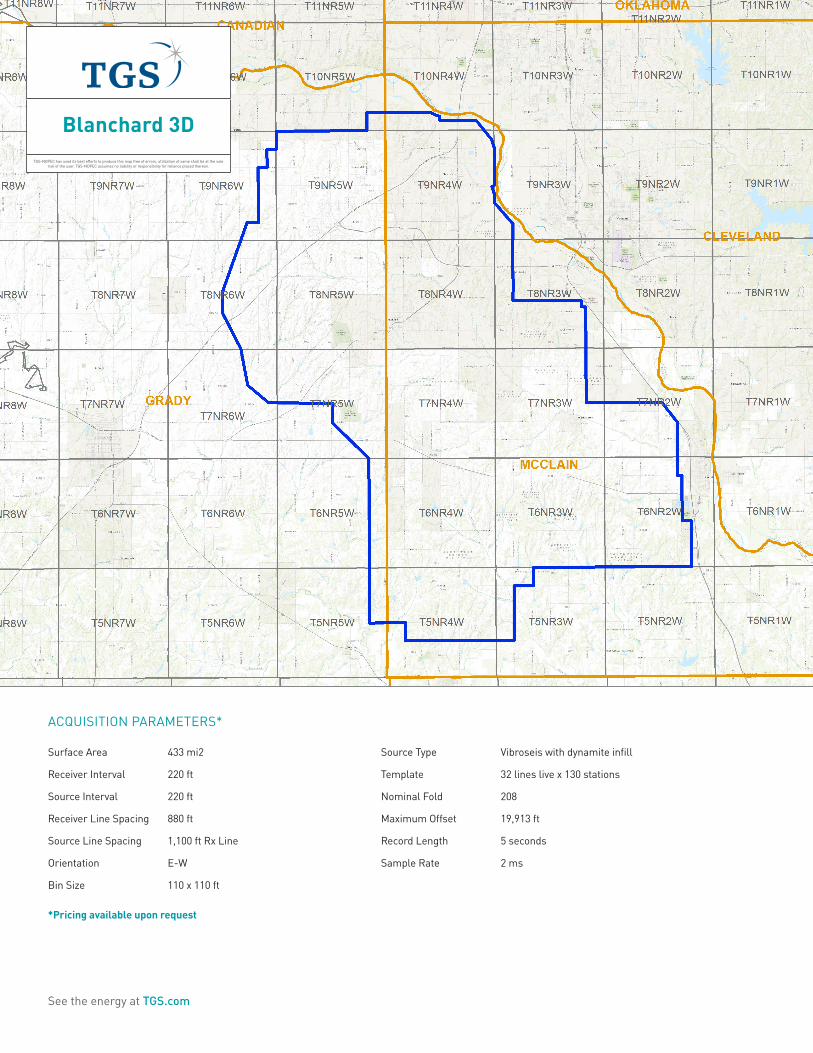
See energy defined. Blanchard 3DMULTI-CLIENT ONSHORE SEISMIC GRADY AND MC CLAIN COUNTIES, OKLAHOMA
See the energy at TGS.com
Blanchard 3DTGS-NOPEC has used its best efforts to produce this map free of errors, utilization of same shall be at the sole
risk of the user. TGS-NOPEC assumes no liability or responsibility for reliance placed thereon.
ACQUISITION PARAMETERS*
Surface Area 433 mi2
Receiver Interval 220 ft
Source Interval 220 ft
Receiver Line Spacing 880 ft
Source Line Spacing 1,100 ft Rx Line
Orientation E-W
Bin Size 110 x 110 ft
Source Type Vibroseis with dynamite infill
Template 32 lines live x 130 stations
Nominal Fold 208
Maximum Offset 19,913 ft
Record Length 5 seconds
Sample Rate 2 ms
*Pricing available upon request
See the energy at TGS.com
Blanchard 3DPROCESSING PARAMETERS
Time Pre-Processing
� Input SEGD data
� Minimum phase conversion
� Merge navigation with seismic trace headers
� Geometry QC, trace edits
� Output geometry shot ordered tapes
� Refraction statics
� Velocity analysis
� Residual statics (first pass)
� Spherical divergence correction
� Surface consistent amplitude compensation
� Noise attenuation, shot domain
� Surface consistent amplitude compensation
� Surface consistent deconvolution
� Velocity analysis
� Residual statics
� Residual noise attenuation
� Surface consistent amplitude compensation
� Trim Statics
� Output pre-processed data with refraction and reflection statics stored in trace headers
Post Stack Time Migration and Post Stack Processing
� Kirchhoff pre-stack time migration velocity analysis (2 passes)
� Output migration velocities
� Kirchhoff pre-stack time migration
� Output raw migrated gathers with NMO
� Mute and stack
� Output raw migration stack
� Apply filter and scale
� Noise reduction and footprint attentuation
� Output processed migration stack
Deliverables
� Raw field data / shot ordered (SEGD)
� Field data with geometry and XY coordinates in the trace headers/shot ordered (2 ms unedited)
� Preprocessed data –with refraction and reflection statics stored in trace headers (CDP sorted)
� Pre-stack time migrated CDP gathers with NMO
� Processed migration
� Raw migration
� Migration Velocities
� 3D migration velocity trace volume
� Processed land source-receiver navigation – (SPS)
� Data processing final report
Depth Imaging (Optional)
� Build initial vertical velocity model by calibrating PSTM velocities with checkshots
� Remove long wavelength statics from data and move data to acquisition datum
� Kirchhoff depth migration
� Estimate anisotropic parameters (delta and epsilon)
� Three iterations of PSDM and tomography
� Final iteration of PSDM and tomography (if required)
� Final VTI Kirchhoff PSDM
� Output depth gathers with NMO
� Residual moveout
� Output depth gathers with NMO
� Stack
� Output raw migration stack
� Noise removal (f-k power or fxy decon)
� Amplitude balance and TVF
� Footprint removal
� Output processed migration stack
Deliverables
� Depth Raw Migration Gathers with NMO
� Depth Processed Migration Gathers with NMO
� Pre-Stack Raw Depth Migration Stack
� Pre-Stack Processed Depth Migration Stack
� Final Interval Velocity Model
� Final Delta & Epsilon models
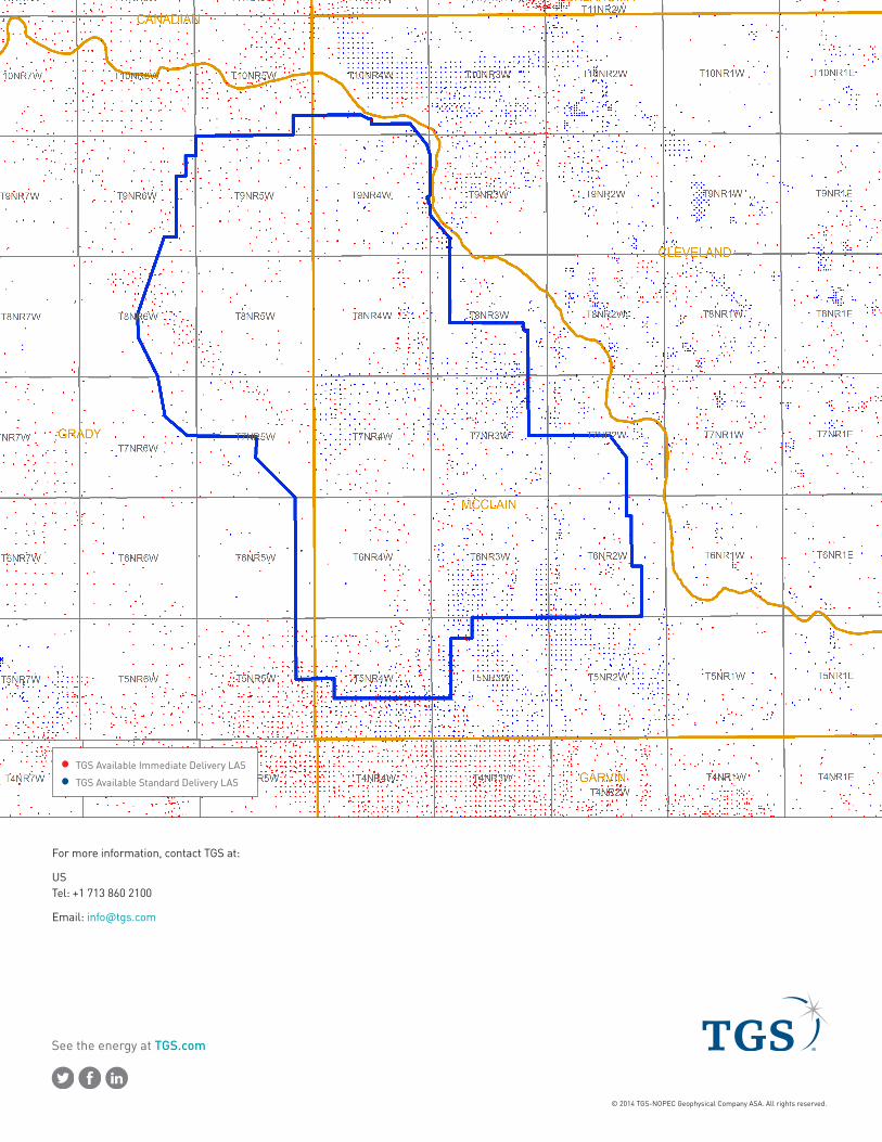
Optional Products
� LAS well logs
See the energy at TGS.com
© 2014 TGS-NOPEC Geophysical Company ASA. All rights reserved.
For more information, contact TGS at:
US Tel: +1 713 860 2100
Email: [email protected]
TGS Available Immediate Delivery LAS
TGS Available Standard Delivery LAS