th):'+• b-u-lb iii''':'':,sure, skin friction and heat transfer...
TRANSCRIPT

I40
HARDCOY $X O
Sm-461129 I~t~H Cuw. 4
FLOW SEPARATIO'N IN 1IGH SPEE 3L1" 11T
A RVIEWl OF THE SrPAN-OF-THE-ART
b-U-Lb
MI-1S S ILE &SPACE SYSTEMS DIVISIO:ý1NDOUGLAS AIRCRAFT COMPANY, NC.SANTA mo-NiCA cALIFORNIA
U/
LAW ULAs'f
Th):'+• I'-. ++::::: A D C r' + ,. o 0L+:: W: s--6,2 III''':'':, u •um. •/. ,

FLOW SEPARATION IN HIGH SPEED' FLIGHT
A REVIEW OF THE STATE-OF-THE-ART
DOUGLAS REPORT SM-46429APRIL 1965
PREPAREO eyt J.E. WUERERTHOR AERO/THERMOOYNAMICS SECTION
PREPAREO ev: F.I. CLAYTONTHoR ACRO/THERMOOYNAMICS SECTION
P EPAREO FOR OENERAL USE Al ANON-CONTRACTURAL REQU R aMtNT
APPROVED ny.4^.J. TAGLIANICHIEF, AERO/THERMODYNAMICS URANCHFLIOHT MECHANICS DEPARTMENT
Best Available Copy
Jti7/L], /MI/SSIL E S SPACE SYSr TJA7f/.. DIV/S/ON

ABSTRACT
A physical explanation is given of the two types of flow separation
classified herein as boundary layer separation and breakaway separa-
tion. A short discussion of the fluid dynamic complexity of the
problem is presented. Such characteristics of separated flows as the
pertinent descriptive parameters, state of flow, length of separated
region, compression process, flow steadiness, and three-dimensional
effects are discussed. The effects of flow separation on the pres-
sure, skin friction and heat transfer distribution are described, and
a review of semi-empirical methods for calculating the critical over-
all pressure rise, the geometry of the separated region, and the heat
transfer at reattachmert is presented.
DESCRIPTORS
1. Boundary Layer
2, Separation
3. Reattachment
'. Pressure
5. Heat Transfer
6. Skin Friction
7. Flow
8. Supersonic

ACKNOWLDGMENT
The authors would like to express their gratitude to D. E. Lapedes
for his thought provoking suggestions concerning the technical con-
tent and his comments on organizing the material in this report.
N!

TABLE: OF COINTETS
SECTION PAGE
Abstract -----------------------------------------------
Acknowledgment -...............................---
Table of Contents -................... vList of Figures .... -.................................. . ix
Nomenclature ........ xi1. ITRODUCTION ...... ......... 12. FLOW SEPARATION PHENOMENA ------------------------------ 32.1 Boundary Layer Separation ------------------------------ 32.1.1 Two-Dimensional Separation ----------------------------- 32.1.1.1 Two-Dimensional Separation - Physical Phenomena -------- 32.1.1.2 Two-Dimensional Separation - Analytical Approaches ----- 102.1.2 Three-Dimensional Separation --------------------------- 122.2 Breakaway Separation ----------------------------------- 14
2.3 Remarks ... ...------------------------------------------ 163- CHARACTMISTICS OF SEPARATED FLOWS ---------- ---------- 173.1 Significant Flow Parameters ----------------.----------- 17
3.2 State of Flow ---------------------------------------- 183-3 Length of Separated Region ----------------------------- 193.4 Shock Wave Penetration of Viscous Region --------------- 19
3.5 Compression Process--------------------------------- 193.6 Steadiness of the Flow --------------------------------- 223.7 Three-Dimensional Effects ------------------------------ 224. PRESSURE DISTRI )ION ---------------------------------- 25
4.1 Dependency on State of the Flow ------------------------ 254.1.1 Boundary Layer Separation ------------------------------- 254.1.1.1 Laminar Separation ------------------------------------- 254.1.1.2 Transitional Separation -------------------------------- 27
4..1.3 Turbulent Separation ----------------------------------- 274.1.2 Breakaway Separation ---------------------------------- 284.2 Free Interaction --------------------------------------- 28
A' n, m,

I
14.3 Pressure Paaetr --------------- -------- 28
4.3.1 Critical Pressure Rise---------- -- --------------- 29
14.3.2 Separation Pressure Rise ------------------------------- 30
14.*3.3 Reattachment Pressurc! Pise--------------------------~-- 3114.3.14 Platerit Pressure Rise -.- ---.--------------------------- 31.14.14 Comments ?ertinent to Specific Geom~etries---------------- 38
14.14.1 Compression Corners------------------------38
14.14.2 Shock Wave Interaction---------------------------------- 41
14.14.3 Curved Compression Surfaces --------------------------------- 44
14.14.4 For-ward Facing Steps- --------------------------------------- 14514.14.5 Rearward Facing Steps---------------------------------- 414.14.6 Bluff Leading Edge -sssssssssssssssssssssss ------- 4
14, 4 *71 Cutouts ------------- --------------------------------- ~~a-- 4914.* 4.8 Remarks-------------------- ------------------------------------------- 514
5. SKIN FRICTION~ DISTRIBUtTION------------------------------ 556. HEAT TRANSFERi DISTRIBUTIONI--------------------------------- 616. 1 Cavity Flow - ---------------------------------- 61.6.1.1 Chapr.man~s Theory -------------------------- f-amp 62
6.1.2 Larson's Ileat Transfer Experiments ----------------------- 636.1.3 Charwat 's Investigation -----------------.--- -- m-m--- 64
6.1.5 Centolanzi' u Investigation--------- ---.-----..... 70
6.1.6 Surface Dist ortion-------.--.71...,........
661,6.1 AEDC Invest igpat ion ---- --- ---------------- -. .. 71
66 16662 HASA Investigpat ion --- -ýM---- ---- 72----.--~-...6.1.7 Summary of Results on Cavities ---------------------------- 72-6.2 Twvo-Dimenasional Compression Corner ------------------------ 746.3 Axisymetric Compression ..
663.1 Becker and Korycinski ---------s--. --~ 5---------- T6.361.1 Laminoar Case------ 8e.6.3-1.2 Transitional Carse ........................- 810
V

II
TABLE OF CONTENTS (Contintiedj
SECTION PAGE
6.3*1*3 Turbulent Case- ---.. ... . ... 82
60302 Ferguson and Schaefer-..................... 83
6.3.3 Summary of Resul.ts on Axisymeietric Compression Corners- 86
6.4 Shock Wave Impingement-. . .... ......... 88
6.4.1 Oblique Shock Impingement ------------ -- 89
6,.4.011 Douglas Study- 89
6.,,1.1.1 Impingement on a Flat Plate----- .. - .--------- 89
6.4.1.1.2 Impingement on a Cylinder ..-...- .---------M------- 92
6o4°1.2 North American Aviation Study -.----------- -- ----- 94
6.4.1.3 Correlation of Pressure and Heat Transfer----------- 94
6.4.2 Swept Planar Shock Impingement - . . . .-----------.. 97
6.5 Rearward Facing Steps---------------------- 976.5.1 Boeing Study -. --------------- 97
6.5.2 N.aysmith' s Work -........ ...-..--------------- I-----100
6.6 Summary of Results on Heat Transfer---------- -------. 102
7. CONI C[UDING REMARKS ................................. 107
7,1 Variables Describing the Problem .-------------.-------- 107
7.P Solution of the Problem -.------.--------------------- O7.3 Present Status of the Problem -.----------------------- 110
8. LIST OF REFiPENC . ... . . . 113

I
LIST OF kIGURF-S
FI~JREPAGE
1 Boundary Layer Velocity Profiles ------------------------ 52 Flow Separation in Viscous Corner Flow ------------------ 7
3 Flow Characteristics at Separation and Reattachment------ 9
4 Separation in Three-Dimensional Flow -------------------- 13
5 Examples of Breakaway Separation ------------------------ 15
6 Comparison of Separation Length for Laminar andTurbulent Boundary Layer -------------------------------- 20
7 Wall Pressure Distribution in the Vicinity of Separation 26
8 Comparison of Pressures on Wall and at Edge of BoundaryLayer --------------------------------------------------- 32
9 Plateau Pressure-Laminar Flow --------------------------- 33
10 Plateau Pressure-Turbulent Flow ------------------------- 34
11 Free Interaction Flow Deflection Angle as a Functioni ofMach Number and Reynolds Number ------------------------- 37
12 Pressure Distribution for Separated Flow ---------------- 3913 Shock Wave Boundary Layer Interaction ------------------- 42
14 Flow Over Cutouts -------------------------------------- 51
15 The Recompression Pressure Rises as Functions of L/H andMach Number --------------------------------------------- 52
16 Critical Closure Length for Cavity Flow ----------------- 53
17 Sample Pressure and Wall Shear Distributions andVelocity Profiles -------------------------------------- 56
18 Sample Pressure and Wall Shear Distributions andVelocity Profile .--------------------------------------- 57
19 Sample Pressure and Wall Shear Distributions andVelocity Profiles -------------------------------------- 58
20 Nicoll's Experiment ------------------------------------- 67
21 Local Heat Transfer Coefficient for Crv,.ty Flow --------- 6922 Centolanzi's Investigation ----------------------------- 70
23 Correlation of Maximum Heat Transfer Coefficient withthe Laminar Displacement Thickness to Cavity Height forFlow Over a Sine Wave Crvity --------------------------- 73
24 Pressure and Heat Transfer Distribution for Laminar Sep-aration at a Two-Dimensional Compression Corner --------- 75
VIm I•m ,m, ~ m m m mm • m n ~ ,• m

LIST OF FIGURES (Continued)
FIGURE PAGE
25 Pressure Coefficient and Heat Transfer Distribution forPure Laminar Separation at an Axisymnetric Flared Skirt- 77
26 Pressure Coefficient and Heat Transfer Distribution forTransitional Separation at an Axisynrnetric Flared Skirt- 78
27 Pressure Coefficient and Heat T-ansfer Distribution for
Turbulent Separation at an Axisymmetric Flared Skirt---- T7
28 Pressure Coefficient and Heat Transfer Distribution fora Laminar Separation at an Axisymmetric Flared Skirt---- 84
29 Pressure Coefficient and Heat Transfer Distribution forTransitional Separation at an Axisymmetric Flared Ski~rt- 85
30 Correlation of the Ratio of Maximum Experimental Stan-ton Number at Reattachment to the van Driest Value atthat Point with the Maximum Experimental Pressure Rise-- 87
31 Oblique Shock Impingement on a Two-Dimensional TurbulentBoundary Layer-------------------------------------- 90
32 Recovery Temperature in Shock Wgve Boundary LayerInteraction ---------------------------------------- 91
33 Oblique Shock Impingemeat on an Axisyrametric TurbulentBoundary Layer --------------------------------------- 93
34 Correlation of Maximum Rise in Heat Transfer Coefficientwith the Maximum Rise in Pressure for Oblique Shock WaveImpingement on a Turbulent Boundary Layer --------------- 95
35 Planar Shock Wpve Interaction with a Two-DimensionalBoundary Layer-------------------------------------- 98
36 Heat Transfer Distribution Aft of a Downstream-FncingStep with a Turbulent Boundary Layer -------------------- 99
37 Heat Transfer Distribution Aft of a Downstream-FpcingStep---------------------------------------------------- 101
X

II
NOMENCLATURE
S1BLDEFINITION UNITS
Cf Skin friction coefficient --.--------......- .. ND.
Cp Pressure coefficient -.-.-.--- ND.
h Heat transfer coefficient............ - BTU/ft 2 .sec-RH Step height or cavity depth -. . ... -- . Inches
K$ Q, N Constants -.-.... ....... ....... N.D.
Length------ InchesL Cavity length --------. ...... m Inches
M Mach number -................. N*Do
p Pressure- --- - -. . . . . . . . . . . . ... . .....m . Lb/&n2
ap Pressure difference-. . ......... . Lb/in2
u Velocity Ft/sec
u* Velocity ratio 1L along the dividing streamline------- N.D.U
R Reattachment point. N. D.
SReynolds number based on diameter- N----- = -- - . .D.R/ Unit Reynolds number -. ... . . -. - Ft"I
Rx Reynolds number based on running length x--.......-.. N,D.
Ry Reynolds number based on coordinate y- - -N.D.
S Separation Point-- ---...... ---- --- N.D.St Stanton number - .. ... . . .- N.D.
T Temperature OR.. --- == --- n
TR Onset of transition ........... .. . . : .D.
x Coordinate parallel to surface and flow direction - Inches
7 Coordinate perpendicular to surfi -e I---- :--- :=-- -. Inches
a Coordinate parallel to surface and perpendicular tofloa direction Inches
* Flow deflection angle-.. -------------- Degrees
Y Ratio of specific heats- .------ --- -�--::===:== .PD,.8 Boundary layer thickness---- . . . -:- Inches
8" Boundary layer displacement thickness -.------ ======= Inches
8s Mixing or free shear layer thickness--- ---- us--ma Inches* Wall deflection angle .......... - Deg.r....- .- - Peles
a Non-dimensional
al

NOMENCLATURE (Continued)
SYMBOL DEFIXitiONS UAIT '
p Density -------------------------------------------- LbM/ft 3
r Shear stress--------------------------------------- Lb/in2
Absolute viscosity ---------------------------------- Lb-sec/ft 2
SUBSCRIPTS
f Final
o Just prior to pressure rise
w Wall conditions
e Conditions at edge of boundary layer
p or plat Plateau value
erit Critical value
sep Value at separation or throughout separated region(for heat transfer)
pk Peale value
max Maximum value
OD Free strear conditions
I Conditions after incident shock
2 Conditions after reflected shock
rer Reference conditions
lam Laminar
turb Turbulent
t Total conditions
r Recovery conditions
b Base conditions
f.p. Flat plate value
D Diameter
exp Experimental value
SUPER'3Ci;IPrS
Values downstream of recompression
- Mean value

FLOW SEPARATION IN HIGH SPEED FLIGHT
1. INTRODUCTION
Flow separation is a phenomenon which has hindered or limited the de-
velopnent of many devices which depend upon the dynamics of fluids
for successful operation. This problem has been particularly signif-
icant to the aircraft and aerospace industries. In low speed flight
the principal effect of flow separation is to cause drastic changes
in vehicle flight characteristics, due to the sudden modification of
the pressure distribution. High speed supersonic flight has posed
certain new problems associated with separation. Not only does the
possibility of undesirable shifts in aerodynamic loading exist, but
large local increases in aerodynamic heating have been noted in re-
gions of flow reattachment. In addition, self induced fluctuations
in pressure due to unstable flow may occur.
This report is the result of an effort to review the present. state of
the art concerning the effects of flow separation on both the general
flow field structure and on aerodynamic heating. However, before con-
sidering these specific areas, it is helpful, if not necessary, to un-
derstand certain basic characteristics of separated flows. First, a
qualitative description of the flow in separated regions is given and
the influences of certain parameters are discussed. Secondly, those
aspects of the flow thought to be critical specifically to the problem
of aerodynamic heating are defined. The present discussion is appro-
priately limited to the case of high speed (supersonic and hypersonic)
fl(w, since most critical problems are limited to this regime.
The plan of this report is as follows. First, in section 2, the condi-
tions under which a flow may separate and the sequence of events lead-
ing to separation are defined in terms of fundamental flow properties,
such as the distribution of momentum in the boundary layer, pressure
gradients, and wall shear. The discussion is extended to briefly cov-
er pertinent analytical ideas. Next, the general physical characteris-
tics of separated flows are outlined in section 3. These introductory

concepts lay the groundwork for the major discussion which is
divided into three parts, namely: 1{i) pressure distribution,
vhIch is interrelated with the overall geometry of the separa-
ted flow region, in section 4. (2) skin friction, in section
5; and (3) heat transfer distribution, in section 6. A sum-
mary of the important features of separated flows and conclu-
sive remarxs are made in section 7.
2
a
2. FLOW SEPARATION PHENOMENON
We may define two broad classes of conditions under which flov separa-
tion may be initiated. The first cless is associated with the separa-
tion of a boundary layer flowing against an adverse pressure gradient.
This cas- has been studied in some detail and the conditions necessary
for its occurrence are fairly well understood, at least for two-dimen-
sional and axisymmetric configurations. This case shall be termed,
for the purposes of the present discussion, "bcundary layer separation".
The second class of separation is associated with flows past bluff bod-
ies and sharp convex corners. Here, the flow may separate even though
the streamwise pressure gradient is favorable. This flow shall be
called "breakaway separation". Less Is understood about the mechanism
underlying this latter type of flow; however, it is an important prob-
lem since it may occur with conventional aerodynamic shapes. Because
of the somewhat different conditions giving rise to these two classes
of flows they will be discussed independently.
2.1 Boundary Layer Separation
Separation of a two-dimensional boundary layer hae been studied ever
since it was first explained by Prandtl in 1904. At present, the
underlying principles of the phenomena may be supposed known. On the
other hand, it is only quite recently that general three-dimensional
separation has been seriously investigated. Much less is known about
the criterion necessary for its occurrence.
2.1.1 Two-Dimensional Separation
2.1.1.1 Two-Dimensional, SCDaration - Physical Phenomena
If we consider the two-dimensional fla'; of a viscous fluid over a body,
the fluid near the surface (the boundary layer) is retarded owing to
skin friction effects. The velocity of the fluid in the boundary layer
varies from zero at the wall to approximately the inviscid value at the
outer edge. If no other forces are acting to further retard this flow,
* Superscripts denote references listed in Section 8.
3

the slope of the velocity profile al Is positive at the wall and
griual'A- ap.roaeh. zerj .t the e-dge of the boundary 'Layer, as U_
lustrated in figure 1-a. However, if in addition to wall shear,
the flow encounters an upstream directed force, the flow is further
Impeded. If the kinetic energy of the fluid is continuously deple-
ted doing work against this force, the flux of oncoming fluid momen-
tum will eventually be balanced by the force and the flow will be
brought to rest. This balancing condition will be experienced first
by the very low momentvm fluid within the boundary layer and nearest
the wall. Downstream of this region the acting force will cause the
fluid near the wall to flow in the upstream direction, creating a
backflov. The original oncoming boundary layer will then separate
where the forward and backward moving flows meet.
The normal velocity gradient at the wall, 9 ) . must be positive when
the fluid next to the wall moves with the stream and negative when the
fluid in this region flows against the stream. It follows that where
the two flows meet 0 ; consequently, the wall shear stress,#Y/W
r a also vanishes. This point on the wall which dividesTW C) YU )y/
these two regions of flow, point S in figure 1-b, is defined as the
separation point.
In most fluid dynamic situations, the force giving rise to separation
is 4n adverse pressure gradient, i.e., the pressure is increasing in
the downstream direction. The remainder of this report shall deal
specifically with this most common case. However, it should be kept
in mind that any force field, for example that created by the inter.
action of a moving, conducting fluid in an electromagnetic field 2
could give rise to the phenomenon of separation.
In a supersonic flow, an adverse pressure gradient may be generated
by the aerodynamic shape of the body, for example a compression cor-
ner, or by an external source such as an impinging shock wave. In
4

UU
ue Ue Ue
BOUN0,AIQ1' LAYE~R ON A SURIPACE-Exri4-FR F=AVORABLLe OR NO P~kV$5URE. GRA-t~lfNt4-
(o.o
70 bQ)bt
BOUNI),^RY LAYE.R ON A. SURFkCrm-JkbVERSS PRE~SSURFE GRAtCAEN-T SE-PAR A-ric* ^-T poIN4T S
FIGURE I

tI
eac cae, he uperson.." flow exemne v% ressw-e rise e-oss
shock wave. Since in a supersonic flow the body moves faster than
the pressure.aisturbance it creates, the disturbance cannot propa-
gate upstream of the body. The shock wave, which is the front of
the pressure rise, is the forward boundary of that region of fluid
influenced by the body. Ideally, then, the shock wave represents a
discontinuous rise in pressure. However, in any real process a
true discontinuity cannot be sustained, and experience shows that
in the region of a shock wave, very steep pressure gradients exist,
i.e. the rise in pressure takes place over a very short distance.
If the shock wave extended throughout the entire flow field, sepa-
ration would be very localized since the adverse pressure gradient
would exist only ever a very narrow region (the thickness of the
shock wave front). Unfortunately, this is not the case. There is
always a region in that part of the boundary layer nearest the wall
where the flow is subsonic. In this region, pressure waves will
* propagate upeotream of the distuXrbance (thus eliminating the forma-
tion of a shock wave) because these disturbances are moving faster
than the fluid. This allows the pressure gradient to spread over a
much longer distance in the low momentum portion of the boundary lay-
er. Experiments have shown that such disturbances may be propagated
sizeable distances upstream, of the order of 10 to 100 boundary lay-3
er thicknesses. In addition to this streamwise pressure gradient,
a normal pressure gradient will also exist since the supersonic flow
field outside of the boundary layer and ahead of the shock wave par-
sists at a lower pressure. The process by which this pressure field
Is established through the subsonic portion of the boundary layer is
called "pressure diffusien".
If separation occurs, the streamlines in the external flow will be
deflected. For the case of a compression corner, illustrated In
figure 2, the effect of separation is to alter the flow geometry
such that the supersonic flow will be compressed in two stages through
6

49,
Ow0
00LL ol
00
UIUR 2 i1257

II
two weaker shoce waves instcad of' one strong--,, sh~ock wave.* lite
pressure rise in the inviscid'Plow field is Identicl -o thai ex-
perlenced by the boundary laYer. Since separai ion "edixc's thl ni -
tial pressure rise because the initial deflecion o:' flh:e 'n./Iscid
flow becomes sriell-r, and since the mechanism o'. sep-tz'tion (a
boundary layer phenomenon) is dep-ndent upon 1he 0ited.* 0" ",.s
pressure rise, It can be seen tha" tIe external inviscid Iflow anci
the viscous separated flow are ini er.`'-pendent throuigh a pressure
interaction. An equilibrium between the two flow fields determino.,
the final na4ure of the flow.
Separated flows :'requenrlly reaItach on the body, !'igure 2. Al rt:-
attachment, the supersonic flow is compressed to IPs final value,
i.e., that value corresponding to the local slope of the body at.
that poin,. That fluid with sufficient momentum to proceed agains'
the reattachment pressure rise continues downstream after reattach-
ment, while that having insufficient momentum is reversed beck into
the separated region. The nature of the pressure rise and local
flow at both separation and reattachment are shown in figure 3.
In a steady flow, the dividing streamline at separati 1 must also
be the dividing streamline at reattachment. If this were not so,
continuity conditicns could not be satisfied, i.e., fluid would
either be continuously injected into or continuously removed fror.
the cavity region. Thus, ideally the fluid in the separation cavity
is a constant mass merely being circulated. The viscous fluid layer
outside the dividing streamline behaves much the same as a continuance
of the original boundary layer. At the dividing streamline, howev.r,
the velocily does not g; to zero as it would at a solid wall, since
momentum is transferred (by the mechanism of viscous shear) from the
external stream through the outer -,!soous layer into the inner vie-
cous region (separated region). it is this continuous transfer of
momentum which sustains the motion of the entrained fluid.
* The terminology of "weaker' and stronger" used here refers to thestrength of the pressure rise across the wave. It is not to be con-fused with the terminc-og-y used to differentiate between the twosolutions of the invis-id flow expression relating freestream Machnumber, flow deflection angle, and shock wave angle.
8

FL v~ . " C-4% 1 A= r%- IS Z)II a* Z#I%
SM-PAR4TION A~t* -REEATTAC"MISNT
P/Pe
AAWVE.R P~eSSURE
(061 PLOW PIFMLCý A.T SMPJAR!AX-IME.
FIGURE 3

The foregoing arguments apply, at least in principle, whether the
boundary layer is lar.inar or turbulent. The mpwor.drfer'ence is
that turbulent flows ere not truly ztendly. Thererere, am is cus-
tomary, time avernge quantities rxy be appl'ed to d:ncibe the
flow. For example, In lurbulent flow, considc.able rt;ipt s exchange
may take pltce between the sepnration region rnd ••e external vis-
cous flow. This tbheorctically invalidates 4he exisience of a
physical divIding streamline. Ho'ever, the rot ,itre average mass
exchange rmust still be zero for eqiIMbr!.tr. onc~tions.
In surnar'y, irf n flow encoun.er. st,'lcer, rdv,'- . pressure rise
to bring th'ý lov mno:nt.nlium fluid In thc briii.'y layer to rest and
establish a reg!on of back flow downs tr-r,,r: ot,' hls point, the on-
coming boundary layer will separate. The orise, of separation will
deflect the external sl ream, changing the flow geometry and, hence,
the pressure dintributlon. Since the pressture distribution in the
external stream, In turn, affecUs the location of seTaration, the
two flows (external Inviscid stregm Fnd viscous flow region) inter-
act until an equilibrium state is r'eached. The dividlng streamline
separating the external stream froe the separated region may be
thought of as the new effective body ,hapxe sensed by the supersonic
flow. The outer edge of the ,.iscous flow region displays velocity
profiles very similar to thone for an attanhed boundary layer. How-
ever, profile charncterintlis change markedly in the innermost por-
tion of the vis.ous flow rogion (the sepaiation region) where
velocities are further reduced, velocity gradients are small, and a
region of reverse flow exista. Separated flows mny reattach. At
reattachunent some boundary lvayr of" finit, thl,---, "r. exist. ant
tends to develop in n-ar nr• ,. dromns' ,-,,:l.
2 1.1.? oTwo-Dnv, (o,-,, S, -,nt.I.o _- Ativilv!/ ;.0 ,1 lvlO,,.
Serious arin].yttcaIl fi'. :ii ,u r , . i I r,,nttnit the prob-
lem of sepirnt ed bourid str' lay! s. reIer.' c.[,.rn! Ot.,t' , th," ,o•ondnry
layer equations are valid ortly fNur attachd ",..,.. In the vicinity
of separation, two of the asnumptions cr.i !vo,, to their development
are no longer valid:
10

i
a. Near separation, significant pressure gradients exist in
the direction normal to the local surface.
b. Downstream of separation, the thickness of the viscous flow
region increases significantly, hence, the boundary layer
thickness (i luding the separatee, region) may no longer be
negligible compared to a representative body dimension.
In piinciple, then, separated flow requires the re-examination of the
complete and very complex equations of viscous fluid motion (the
Navier-Stokes equations) to determine if any simplifying assumptions
can be made. Unfortunately, the flow geometries and boundary condi-
tions of separated and reattaching flows are so complicated that no
generalized simplifications have been found. Hence, at least for the
present, an exact solution of the problem does not seem feasible.
Several attempts have been made to develop approximate analytical
solutions to the problem of separation; (references 4, 5, 6, 7, 8, and
9) however, progress has been slow and limited primarily to laminar
flows. Of these attempts, the more elaborate method of Lees and
Reeves9 appears to be the most general and promising. This method con-
sists of an approximate solution to the momentum boundary layer equa-
tion, and in many respects is similar to methods developed for attached
flows 1 0 p'31 Separates flows, however, differ basically from attached
flows in that they have a strong pressure interaction with the external
flow and that the velocity profiles display a region of reversed flow.
Therefore, specific correlation parameters which have been used for
attaehed flow solutions which assume that the velocity profile is a
function only of the streamwise pressure gradient outside of the bound-
ary layer are not directly applicable to the present case. The approach
taken is to seek a simultaneous solution to the zeroth and first moments
of the boundary layer momentum equation, i.e., the momentum integral and
energy integral boundary layer equation. Using this technique, the
11

momentum equation itself need not be utlsfIled tit the surface. Iuis,
more restrictive parameters used in the attached flow solutions may
be replaced by a velocity profile parfmieter which is related to the
shear stress at the wall. This latter dependency posesses a sIgnifI.-
cant physical meaning for the problem cf separated flows. The method
is capable of producing velocity proftler with reversed flow even for
the limitlng case of zero free stream. velocity gradient. The effects
of heat transfer are included in the analysis.
2.1.2 Three-Dime:isional Seraration
Thus far, the concepts discussed have applied primarily to two-dimen-
sional flows. No serious qualitative complication is introduced In
the consideration of boundary layer separation in axially symmelric
flows. InsteAd of the locus of points describing separation from the
surface being a line, it is now a circle around the body perpendicular
to its axis of symmetry.
For general 1three-dimenslonal flows, the problem of boundary layer
sepnration is much more complex and remains relatively unanalyzed.
Much of the significant work to date is reported in references 12
through 18. The principal difference between two-dimensional and
general three-dimensional flows may be deccribed as follows. In a
two-dimensional flow, the fluid in the boundary layer is generally
fcrced Into th" external flow if the pressure gradient Is suff'c.enily
strong, thus causing separation from thc wall; however, in three-
dimensional eases, tl:e fluid particles can escape sideways along the
wail. Hence, the deflniation of separation Is beset with considerable
complexity. Maskell13 suggests that the probler be viewed from the
standpoint of limiting streamlines, !.e., the streamlines of fluid
particles that pass infinitely close to the surface. if separation
exists, two distinct sets of limiting streenlines lie on the surface,
one representing forward flow and thr c ie:r, reversed flow. The locus
of separation points is then the bcundary between these two sets of
limiting streamlines ane the flow field Is divided into two -egions
by a stream surface starting at the body, ns illustrated in figure 4.

SEPARATION IN
THREE -DIMENSIONAL FLOW
ow~owi~
FIGURE 4
13

2.2 Breakaway Separation
In certain instances, the flow may separate even thougnr. t1h inviscid
streamwise pressure gradient is favorable. This type of flow we hrve
already defined as breakaway separation. Some examples a:'e ,lius--
ted in figure 5.
In the inviscid sense, breakaway separation in a superson-',- flow rme'."
be related to the maximum turrning angle for Ihe f !':,. .e., iha an-
gle through which the flow becomes completely expanded. Ideally, -!n
evacuated region results when the geometr'ic angle exceeds This value.
At low supersonic Mach numbers the maximum, turnng ngle is qu!te
large, e.g., for a two-dimensional flow using the P-andtl-Meyer
(isentropic expansion) criteria, emax = 130.h 0 for M = 1. However,
as Mach number increases, this maximum angle decreases quite rapidly;
at M =10, = 28.20 and at M = 20, m = 14.30. This simple mod-a i0 max max
el becomes much more complicated when entropy layers from upstream
shock detachment and thick boundary layers create a region of low Mach
number flow near the c'orner. 1 9 The inviscid evacuated cavity now be-
comes a viscous separated region, fed by the low energy fluid from the
boundary layer. Of equal importance is the pressure rise due to down-stream recomresson.221 This pressure rise will contribute to the
reversal of flow back into the separated region which, In turn, In-
fluences the size of the entrained fluid region. The characteristics
of the flow within the entrained fluid region are identical to those
described for boundary layer separation. Analytical models describing
the fluid mechanical phenomena of breakaway separation are available
in references 20 through 37. Intuitively, the phenomenon ma:' be
thoughtto occur when the centrifugal force ;.ast the curvature (corner)
cannot be supported by the radial pressure gradient. For this case,
the boundary layer equations break down since one of The basic assump-
tions for their formulation was that the surface curvature was smnll,
i.e., of the same order of magnitude as the boundary layer thickness.
Again, the complete Navier-Stokes equations must be re-examined before
any simplifying assumptions may be made for this problem.
14

SEPAg-RWIOt
FIGURE 515

2.3 Remarks
An exact solution to the overall problem of viscous flow separation
does not, at least at present, seem feasible. Because of our limit-
ed knowledge of flow in separated regions and its interrelation to
the entire flow field, no simplificatlons of ihe very complex com-
plete equations of fluid motion seem to be Justified. At present,
approximate analytical solutions relying partially on empirical cor-
relations seem most promising; however, results have not been gen-
erally applicable to practical situations. Therefore, the engineer
has had to resort mainly to experimental Investigation to study his
particular problems. To date, a substantial amount of such work has
been completed. The remainder of this report deals primarily with
the coverage of the highlights of these Investigations and the use-
ful, but limited, engineering tools derived from them.
16

!I
3 CHARACTERISTICS OF SEPARATED FLOWS
The enineer is concerned primarily with determining the pressure,
skin friction, and heat transfer distributions for the fluid motion
over a specified configuration. However, before these topics are
considered, much insight into the interpretation of availabl.e experi-
mental and analytical results pertinent to separated flows may be
gained by considering certain properties peculiar to these flows.
Though the characteristics to be discussed are closely interdepen-
dehnt, they will be dealt with as discrete entities in order to iso-
late their significance. Some of these more prominent aspects
follow.
3.1 Significant Flow Parameters
For attached flows, neglecting displacement effects of the boundary
layer on the external supersonic flow, the behavior of the boundary
layer depends mainly on Reynolds number, whereas conditions in the
external inviscid flow are dependent primarily on Mach number. The
physical significance of these two flow parameters may be explained
as follows:
a. Mach Number
Mach number may be regarded as a measure of the compres-
sibility of the fluid. In the important case of the
adiabatic inviscid flow of an ideal gas, changes in pres-
sure, temperature, and density of the flow along the body
may be shown to be a function only of body shape and Mach
number.
In general, as Mach number increases, the flow in the
vicinity of the body becomes more complex. For example,
separation normally. results in multi-shock (figure 2) or
expansion-shock (figure 5) flow fields. As Mach number
Increases, vave angles decrease and these flow processes
tend to merge in the region of reattachment.
17

b. Reynolds Number
Rieynolds number may be thought of as the 'etie of the
inertia force to the viscous force in the shea- layer.
in continuum flows, the grovth of the shear layer, mo-
mentum transfer, and heat transfer are .c.4y depen-
dent upon Reynolds number. This is true for botn attached
and separated flows.
As has been previously explained (Section 2. 1.!.Ž, "ne phenomenon
of flow separation is the result of a stron,- i:it;:- on between the
viscid and inviscid flow fields. Thereforc, i'- cdescribin; sep&rated
flows both Mach number and Reynolds nuabe.- ar iz:pcrtant.
3.2 State of Flow
Experiments show that separated flows are characterized by the pre-37
vailing type of boundary layer. That is ti.. say, tnere are certain
basic features of the flow which depend DriTmari!:J on vhether the
boundary layer is laminar, transitional, or turbulent &tn,! which are
more or less independent of other flow and reometrizca parameters.
Therefore, it is convenient to define the -ossible recizc:s in the
following manner:
a, Pure laminar - The flow remains lam•inar thrOUghOUt the re-
gion of separated flo.''; i.e., transition
occurs downstream of r'~ttac~uent,
b. Transitional - Transition occurs bet'ween tne separation
ana reattachment poitl;.
c. Turbulent -nThe boudari iayer i3 turbulent throurhout
the entire ;rnarnted rei.-ien; i.e., transi-
tion occurs. ur:strean of t*.e 3eraration point.
The disti%.ct differences in flow charh.teri<'ic- ozscrved between the
above rpeine, are attributed mainc., to the ,reater effective momentuP.
transfer In t-rbultent b.tunrar-: iaiers. Thu-:! the lncation of transi-
tion with resDect to sevaration and reattach'Tent i., "-z-,rta:.t.
18

I,
3.3 Length of Separated Region
In general, for identical free stream conditions and geometry, the
length of the separated region in flow with a laminar boundary lay-
er will be considerably greater than that with a turbulent boundary
layer. The reason is that the greater momentum of the fluid in the
turbulent boundary layer, due to the increased effective viscosity
in turbulent exchange, enables the fluid near the wall to proceed
against much greater rises in pressure before the equilibrium be-
tween pressure and momentum forces is reached. Hence, separation
is delayed in a turbulent boundary layer. As an example.. for a for-
ward facing step, figure 6, it has been observed for identical step
height and free stream Mach numbers that the lergth of laminar sepa-
ration was four times greater than that for the turbulent separation,
even though the overall pressure rise associated with the latter case
was three times greater. 38
3.4 Shock Wave Penetration of Viscous Region
Shock wav.is may occur in the vicinity of separated flows due either
to flow deflection caused by the separation and/or external sources
(shock impingement) which may give rise to the separation. The fi-
nal position that a shock wave may assume with respect to the viscous
flow field is governed mainly by the state of the flow. Shock waves
may, of course, occur only in supersonic streams. If the velocity
profile is gradual, such as for a laminar boundary layer, the dividing
line between subsonic and supersonic flow will lie farther from the
surface than it would be in a turbulent boundary layer of the same
thickness. Hence, a shock wave may "penetrate" a greater distance in-
to a turbulent boundary layer. This property gives rise to the funda-
mental difference in -hock structures observed between laminar and
turbulent interact ions.3
3.5 Compression Process
The combined characteristics of length of the separated region and
shock penetration strongly influence the compression process that the
19.

080
4 -j
32
"FGUE
20.

inviscid supersonic flow undergoes. For illustration purposes, we
may use the example of flow past a step, which has been already par-
tially discussed, refer to figure 6. For both laminar and turbulent
flows, the effect of separation is to alter the effective body shape
to more or less resemble a wedge with a somewhat curved approach.
Because the region of separation for the laminar case is longer, the
external flow is turned more gradually and through a smaller angle;
hence, the resultant pressure increase is less than for the turbulent
case. Compression over this geometry near the wall takes place
through a series of weak waves. These wavelets then coalesce to
form a shock wave some distance outside the boundary layer. For the
tirbulent case, the shorter separation region results in a consider-
ably larger turning angle and a more severe approach curvature; hence,
coalescence of the compression wavelets occurs closer to the surface.
The combined effects of rapid coalescence of compression wavelets
plus the sonic line being deeper in the boundary layer accounts for
the observation that for turbulent flow the shock waves appear to
emanate from a point in the boundary layer.?7
The experimental observations cited above allow us to qualitatively
discuss certain details of the flow field. First of all, for the
turbulent case, since the shock wave emanates from the boundary lay-
er, the external flow fields on each side of the shock wave would be
expected to be nearly isentropic since the shock wave itself is quite
straight. For the laminar case, the compression wavelets do nct coa-
lesce as rapidly and the flow field, consequently, must be examined
more carefuly. Near the new effective turning surface (edge of the
mixing layer), the flow Is turned quite gradually; hence, the process
may be thought to be more or less Isentropic in this vicinity. How-
ever, as we approach the region of convergence of the wavelets, the
compression process occurs more rapidly; hence, an entropy gradient
will occur between the effective turning surface and the shock wave.
This condition would be expected to give rise to a vorticity field
21

In the external flow, and the extent of such an action is consider-
ably greater for a laminar case.
The above discussion is limited to low and intermediate supersonic
Haeh numbers. At high (hypersonic) KMch numbers, the flow field be-
comes considerably more complicated. Shock wave-boundary layer in-
terhjctions, caused by the rapidly growing boundary layer displacing
the inviscid flow, give rise to highly curved shock waves even for
compression by corners and wedges. This effect results in a non.
uniform (non-isentropic) flow in the inviscid field between the
shock wave and the boundary layer. Thus, an entropy gradient will
exist in the inviscid flow field regardless of whether the separating
boundary is laminar or turbulent.
3.6 Steadiness of the Flow
It has been found that, in general, the flow in a laminar separated
region is steady, i.e., at any fixed point in the flow field the
fluid motion is independent of time. On the other hand, this is not
the case for the transitional and turbulent regimes. Transitional
separations are normally quite unsteady in the region between the
transition and reattachment points. This is to be expected since
the phenomenon of tranittion itself is an unsteady process. Chapman*s a
experiments indicate that the unsteadiness associated with turbulent
separation is considerably less than for transitional separation.
This is not to say, however, that unsteadiness in turbulent separation
in not signlficint. In fact, the experiments of Charwat 3 9 ' 0 for flow
over notches show that considerable mass exchange may take place be-
tween the separation cavity and the external flow when unsteadiness is
present. This phenomenon 3ppears to play a major role in the mechanism
of neat transfer from the separated region.
3.7 Thret Dimensional Effects
Separated flows rarely are completely two-dimensional in either prac-
tice or experiment. In particular, it hao been noted that Ic-al three-
dimensional flows may exist in the separated region ahead of a

two-dimensionai step wkenever t.AnSitn I: close to the point
.f separation37 and when a turbulent boundary layer flows over
a notche9 In general, noticeable three-dimensional effects are
accompanied by considerable unsteady flow activity- however, the
converse is not necessarily true.
One particular three-dimensional effect that has been noticed in
experiments is the existence of regularly spaced longitudinal
striations at and downstream of reattachment, as indicated by sub-
limation and oil techniques. Ginoux reported the existence of these
striations for laminar separated flows in references 40 and 42. His
models included rearward and forward facinp steps (bcth two-dimensional
and axisymmetric) and two-dimensional compression corners. lie found
that the range of "wave lengths" (spanwise distance between striations)
that existed for the rearward facing steps could be correlated with
the ratio of step height to boundary layer thickness at separation.
He also tentatively concluded that since similar but weaker stria-
tions were found prior to separation, these striations indicated
the existence of flow phenomena that were related to the flow stability.
In references 36, 43, and 44 similar striations vere found in the re-
attachment region behind rearward facing steps. Strack found that
correlnting "wavelength" and step height gave results in agreement
with Ginoux's laminar data. Roshko, in reference 36, attributes
these striations to Gortler-type vorticea.
23

14. PR E DISTRIBUTION
In this section, the overall effects of flow separation on the pres-
sure distribution and the dependence of various pressure parameters
on the flow are discussed. A knowledge of the wall pressure distri-
b'ution is esbential to the aerodynamicist in order to calculate the
forces on the vehicle. However, other useful information can be ob-
tained. To the experimenter, the wall pressure distribution gives
quite an accurate picture of the separation geometry; namely, the
length of the separated region and the slope of the dividing stream-
line separating the external flow and separated region. Pressure
data have also been used to predict other properties in regions of
separated flow. For example, Sayano45 has correlated heat transfer
"--fficient with pressure distribution for the cause of shock im-
pingement. Such a correlation facilitates the prediction of heat
transfer rates since wall pressure is considerably easier to measure.
4.1 Dependency on State of the Flow
4.1.1 Boundary Layer Separation37The experiments of Chapman, et al, show that for P •-ven geometry,
the location of transition relative to the separation and reattach-
ment points it; dortinsnt in controlling the characteristic features of
thepressure distribution regardless of other flow parameters. Hence,
it is proper to categorize pressure distribution characteristics in
accord with the previously defined states of flow. Typical wall pres-
sure distributions for laminar and turbulent separated boundary layers
are shown in figure 7. Pertinent nomenclature of the d,"stribut~ous is
illustrated. Tt.e dictribution for the transitional case is more or
less a composite of the two illustrated cases. In a general sense,
the characteristics of the pressure distribution iii a separated bound-
cry layer may be described as follows.
4~.l..1 Laminar Separrtion
Or. a relative basis, pure Is-ninar separatlons usually involve rela-
tively small pressure changes and small pressure gradients. In this
25

ZiaHt
2 RA ISI I W
• I l _ I_
FIqGURIE 7

regime, the pressure rises to a plateau and remains almost constant
over most of the separated flow region to reattachment. The plateau
pressure is representative of the pressure in the so-called "dead
air region." The remainder of the pressure distribution depends up-
on the flow deflection at reattachment.
4.l.1.2 Transitional Separation
At separation, the flow is still laminar, so the pressure distribu-
tion upstream of transition is quite similar to the laminar case ex-
cept that the plateau pressure persists ov-r a shorter distance. If
transition occurs quite close to separation, however, there may be
little or no plateau region due to the energizing of the dead-air
reg.on by turbulent exchange. This increased momentum transfer also
gives rise to more severe pressure gradients after transition. An
abrupt pressure rise is often found to occur at the location of tran-
sition. This is especially true when transition occurs only a short
distance upstream of reattachment. However, it is not necessary that
transition in a separated layer be accompanied by a rapid pressure
rise or that abrupt rises in pressure necessarily indicate transition.
If transition is far upstream of reattachment (near the separation
point) transition may occur in the separated boundary layer (mixing
layer) under conditions of nearly constant pressure. Also, if a re-
attaching boundary layer is very thin, a relatively rapid pressure
rise (not indicative of transition) may occur. In general, it is well
to compare pressure plots in all three regimes before attempting to
correlate a particular phenomenon with an irregularity in a particular
characteristic of the pressure distribution.
4.1.-.3 Turbulent Separation
Turbulent separations display rather abrupt pressure variations near
both the separation and reattachment points. No large pressure plateau
is observed for this regime; the pressure usually rises continuously
to its final value. The plateau value is Indicated by either an
27

I
inflection point In the pressure curve or a small plateau, depending
on the length or the separated region.
4.1.2 Breakaway Separation
In general, the basic featureG of the pressure distribution relevantto "breakaway separation" are quite similar to those Just described
for "boundary layer separation". That is, the nature of the pressure
gradients and relative magnitudes of the pressure chsnges are highly
dependent on the state of the flow. The main difference between thetwo regimes is that, since the s'arface is convex, the external flow
expands and, hence, for breakaway separation, a pressure decrease
rather than an Increase Is noted in the vicinity of separation. Theflow then recompresses at reattachment and approaches the value ex-
pected for attached flow.
4.2 Free Interaction
Certain properties of the pressure distribution within the separated
region may be independent of the surface geometry causing the flow to
separate. That is to say, such characteristics are determined only
by the interaction of the oncoming flow with the adverse pressure
gradient and are not dependent upon the magnitude of the overall pres-
sure rise causing separation. Such a flow process, one which givesrise to properties Independent of the geometry, is defined as a "free
interaction". Two important pressure parameters may be expressed as
free interaction functions: these are the pressure rise to the sep'ara-
tion point and the pressure rise caused by separation. These param-
eters are discussed in detail in the following section.
4.3 Pressure Parameters
Several Investigntors of separated flows have found it useful, for
the purposes of Interprelation of data and the development of correla-
tion formulas, to define certain parameters pertinent to specificcharacteristics of the pressure distribution (refer to figure 7). Some

frequently used quantities are define-d as follesv, together vith
their dependency on Mach number and Reynolds number.
The importance of the location of transition relative to separation
and reattachment has already been pointed out (section 3). There-
fore, we must bear in mind that any change in a flow parameter Ahich
affects transition can also directly change the pressure distribution.
4-.3.1 Critical Pressure Rise
The critical pressure rise is defined as the minimum overall pressure
rise required to cause separation. This quantity is usually express-
ed in terms of the critical pressure rise coefficient,
C f-P 2 Lf(3.1)Pcrit (1/2) 7Yi i rol
Donaldson anwd Lange have reasoned, from ccnsideration of the physi-
cal phenomena, that the crltical pressure rise should be controlled by
the wall shear. -0 , boundary layer thickness, 5o, and stream conditions
"No'' pU '. Just priol to separation, i.e.,
Pr - o- " ('o, Poo, M, u0, %) (3.2)
By the principle of dimensional homogeneity, the above relationship
may be replaced by a simpler relationship in terms of dimensionleas
groups, namely:
P o( o (33)(1/2) P 0% (l1/2)po U0 )400 / 0
Or, since skin friction depends on the local Reynolds number and local
Mach number,
C - F (R , . (3.-4)Pcrit 4 xO 0 )

I
Recent experimen*,al results Indicate that CPcrit depends on Reynolds
number in approximately the following manner.
Laminar Flow: C -r R -1/4 (3.5)
Turbulent Flow: C -'.- R -1/10 (3.6)Pern!t
It can be seen that CPCr is a much stronger function of Reynolds
number for laminar than lor turbulent boundary layers. The effect
of Mach number on Cp is greatest for lower values, i.e.,
1<Mo< 4.0. Experim s show that for both lminar and turbulent
flows C Prit "" (M - 1)1/4. Experiments also show that Cpc t is
more or less independent of the specific geometry, although t asmay
not prove to be a general rule, especially at higher Mach numbers.
As previously discussed, the overall pressure rise required to sep.-
rate a turbulent boundary layer Is much greater than that required to
separate a laminar boundary layer. For example, for 1.5<Mo< 3.0 and
Rx = 1 x 10⁶, Cpcrit(turb)• 10 x CPcrit(lam) for an incident shock
wave.
4.3.2 Separation Pressure Rise
Separation pressure rise is defined as the rise in wall pressure at
the actual point of separation. As separation usually occurs under
the condition or free-Interactlon, the pressure rise to this point
is more or less Independent of the mode causing it. For lamninnr and
transitional flow, Cp R , and the separation pressure risePsep O 0for a given Mach number and Reynolds number are about equal. This Is
to be expected since both regimes are essentially laminar at the sepn-
ration point. For turbulent flows, C psep^- 10 The separationPsep o
pressure rise increases with ?"qch number; however, wove angles are
usually quite small; therefore, Cpsep decrease3 as Mnch number

increases. The separation pressure rise Is usually about 1/2 and
2/3 of the plateau pressure for laminar and turbulent separations,
respectively.
-.3.3 Reattachment Pressure Rise
This is the pressure rise at the point of reattachment. In lami-
nar flow, the pressure rise to the reattachment value is approxi-
mately the same as the pressure rise to the plateau value. For
turbulent flow, however, the reattachment pressure rise is usually
about 1/3 to 1/2 of the peak or overall pressure rise (figure 7).
The reattachment pressure is greatly dependent on the particular
geometry; hence, flow properties at reattachment cannot be view-
ed from a free interaction basis.
-.3.4 Plateau Pressure Rise
The plateau pressure rise may be defined as that pressure rise re-
sulting from the external flow deflection caused by separation.
Because the flow within the separated region is of relatively low
energy, the pressure of the deflected external flow Is impressed on
he separated region in much the same manner that the external pres-
sure is impressed on an attached boundary layer. Hence, the pla-
teau pressure and the pressure at the edge of the separated bound-
ary layer may be considered identical. This relationship of the
wall and external flow pressures !s shown in figure 8 for the case
of a compression corner. The gradual gradients along the wall
(dotted line) are attributed to the pressure diffusion phenomenon
vhich takes place in the subsonic portion of the flow. The indi-
cated length, LF.,., represents that region in which the adverse
pressure gradient reacts with the oncoming flow, i.e., the free
interaction region.
31

COMPARISON OF PRESSURES ON WALL AND AT EDGE OF BOUNDARY LAYER
pli4edge of boundary layer--- --
P/
LL //
Kr,FIGURE 8
Figure 9 shows a plot of laminar flow plateau pressure data as a
function of Peynolds and Mach number of the oncoming floW.I, 8
The data shows good correlation for several geometries ; namely, com-
pression corner, incident shook and forward facing step geometries,
thus substantiating the argument of free interaction. The data points
for l< Mo< 16 may be approximated by the following empirical relation-
ship which is Indicated by the curve on figure 9.
C - .6o [A (M2_1)] -1/4 (-7Pplat (Laminar) 0
Certain experiments 3 "T Indicate that the phenomenon of free Inteiactlon,
as previously defined, Is not generally applicable to the problem of
turbulent separation. However, the correlation of' a reasonable amount
of experimental date a7 for the same flow model geometries considered
in laminar flow shows that plateAu pressure Is more or less indepen-
dent of these georetries for turbulent flow (see figure 10). Care mupt
be taken in exlendnr these date to other geometries. The following
equation approxlmtere the Rxo and Mo dependency or plateau precsure *r-
efficient for turbulent flow

II
I-- -
I 2
(00
33

LLIc
(0
40
IIN
F,,
OIFRU.
"- 0
FIUR 10

Pplat(tubuent) 0
It has been argued that the plateau and critical pressure rises are
necessarily identical. 7 The basis for this argument is that the
flow field resulting from a shock-boundary layer interaction can
exist only in one of three possible stable conditions, namely:
a. The overall pressure rise is less than the plateau pressure
rise. Hence, the flow remains attached. This may be de-
fined as a "weak interaction".
b. The overall pressure rise is Just equal to the plateau pres-
sure rise. Here the flow still remains attached, but the in-
teraction is completely self-induced by the mutual dependence
of the viscous and inviscid flow fields. The interaction of
the adverse pressure gradient with the oncoming flow is inde-
pendent of the geometry.
c. If the overall pressure rise becomes greater than the plateau
pressure rise, the attached flow becomes unstable. Stability
is achieved by the separation of the boundary layer, resu3ting
in a modified effective geometry giving rise to stable shock-
boundary layer interaction, such as shown in figure 7. Here
again, the strength of the leading shock wave is determined by
mutual interaction of the viscous and inviscid flow fields and
is independent of the "oody geometry giving rise to separation.
From the above conditions, it would appear that the plateau pressure
rise and critical overall pressure rise are identical providing that
initial separation is continuous and free from any hysteresis effects.149
Kuehn made rather extensive experimental measurements to determine
the critical overall pressure rise necessary to cause separation. His
values for C were somewhat hi j ;her than C . This is possibly
35

I|
due to the difficulty In experimentally detecting the exact onset
of separation. The criterion used was to assume that separation
occurred when the pressure. distribution curve changed from a curve
with one Inflection point to a curve with three inflection points,
i.e., when an Incip!ent plateau pressure developed. This technique
certainly detects the onset of significant separation; however, the
criterion Is not necessarily unique. HakkInen, et LI.I. 0 conducted
a similar investigation for laminar boundary layers, but in addition
made wall friction measurements. These results, based on the more
fundamental criteria of zero wall shear at separation, did show that
the pressure rise to cause separation was of the sar.e ,magnitude as
the plateau pressure. Nevertheless, because of the lack of complete
data, there appears to be a. significant need for more detailed ex-
perimental measurements of the Incipient separstion for both laminar
and turbulent flows, especially if the free-interaction phenomenon
is to be used as a basis for analysis.
One additional piece of useful information may be developed from the
plots in figures 9 and 10.47 Since the pressure coefficient in a su-
personic flow is uniquely determined by Mach number and flow deflec-
tion angle, these data may be re-arranged to show the interdependence
of flow deflection angle, Reynolds number, and Mach number. This is
done in figure 11 which more clearly shows the nature of free-inter-
action phenomenon. The result shows that for a given Reynolds number,
Mach number, and state of flow, the angle of deflection of the separa-
ted flow is uniquely determined. It must, of course, be remembered
that the foundation of this observation is experimental and limited
to specific geometries. The result, however, is applicable to many
practical aspects of separated flows, primarily in determining the
extent of the separated region, especially in situations where either
the separation or reattachment point is fixed.

OFLECPTION, AWMCLruo NS A FUCN-CIONS 0 V& * A rat O&AS stLAMMCn) AnJvq% tMIt.emn mq MLACA¶M2.r
4LI)
IL
1104
4,,
MACR- NUlvieRk NAC
FIGURE I1I
37

I
4.4 Comments Pertlnent to Specific Geometries
Several representative pressure distributions for specific gu.ometries
are illustrated in figure 12. Limited analytical techniques have
been developed for calculating the length of the separated region and
the plateau pressure ris4. These are based primarily on experimental
results and are discussed under the following headings, together with
properties of the pressure distribution which are peculiar to the
specific geometry.
4.4.1 Compression Corners
The flow in a compression corner may exist in one of two possible
equilibrium positions. if the overall pressure rise is less than the
critical value, the flow remains attached. However, if the overall
rise exceeds the critical value, the flow separates, modifying the
effective body geometry in such a manner as to compress the flow in
two stages (figure 12.1). The extent of the separated region is deter-
mined by the mutual interaction (equilibrium) of the viscous and in-
viscid flow fields.
Typical surface pressure distributions for separated flows over'com-
pression corners are shown in figure 12.1. The pressure rise across
the first shock, i.e., pressure rise due to separation, is quite evi-
*dent for laminar and transitional flows, as may be seen by the "pla-
teau" in the pressure curve. In the turbulent case, the plateau pres-
sure rise is characterized by an inflection point in the pressure
cUrve. A distinct plateau is usually not observed in turbulent flow,
since the length of the separated region is quite short. In both
cases, the pressure approaches the Inviseld value after reattachment.
If the pressure distribution is known, the geometry of the separated
region, I.e., the location of the dividing streamline, may be det-
mined with reasonable accuracy. The separation point for laminar and
transitional flows occurs about where the pressure rise is about one-
half the plateau value. In turbulent flow, separation occurs where

FOR SS -z~rt VLow
(cl
I-IS
4)NO SEPAAI@
L4)1()()()
p/P
_ _ _ _a , __ _ _ _ _ _
'9 __________CI ____ ______Scum
a.)(6)Cc'
39

the pressure rise is approximately two-thirds the value of the pla-
teau value. Once the separation point has been established., the
dividing streamline may be drawn, since its slope (the flow deflec-
tion angle) is uniquely determined, knowing Mo and the pressure rise
due to separation.
Analysis of the problem of flow separation over a compression cor-
ner is somewhat complicated by the fact that neither the separation
nor reattachment points are known. However, sufficient data have
been made to correlate certain flow parameters which are independent
of the geometry, namely:
a. The effective deflection angle formed by the separated
flow as a function of Mach number and Reynolds number
prior to separation (see figure 11).
b. A reference separation length as a known function of the
pressure distribution, namely the initial, plateau, and
final pressures.
Consi dering the possible, ways .1e/o can vary, the following ex-
pression can be derived.47
(sex) a ref (3.9)60 ý0 r, C
where
'ref Pop " PP (3.10)
The required quantities to complete the calculation based on experl-
mental data for 1< V° ( 7 are as follows:

Laminar Flow Turbulent Flow
No34 f a2.0 M -2.8
R -2.0 X 10⁵ Bx u'2.0 x 10⁶
oref Oref
K - 105.0 1 v 4.15
Insulated wall Insulated wall
Knowing the separation length and flow deflection angle, the separa-
tion geometry is determined.
Oertain geometrical limitations exist to the above criteria. If the
compression surface is too short or the turning angle, e, too great,
the flow will reattach at the end of the compression surface, the
limiting case of 0 a 90 being the flow ahead of a step. For these
cases, the extent of the separated region is determined solely by
the effective turning angle presented in figure U,, since the reattach-
ment point is known a priori.
4.4.2 Shock Wave Interaction
A boundary layer may separate locally as the result of the pressure
+ise associated with an impinging shock wave. The perturbing shock
wave may be generated by a nearby body causing an oblique shock inci-
dent to the boundary layer, or by a protuberance from the plane of the
boundary layer, giving rise to a swept planer type shock wave, figure
13.
Of these two types of shock induced separations, that resulting from
an incident, shock wave is the simplest and best understood case (ref-
e rences 45, 46, 48, 49, 50, 51, 52). Basically, the shock wave
41

SHOCK WAV&~BOUNDAMY I~~~IMeA.TO
"w' PLANSd. Siow WFcmN-V. SONoRE t#1.t'I I EFL~~r
S"0cwr GE-MN-MATo%:*
104CIME-NT S~HOCK r
P~ZSMru8RRArloN
Lek~INrm F-C>GrE S1HC~.Nc-.4
~Z SLIP SURFACE.
FIGURE 13

impinges on the boundary layer, establishing a Jump in pressure at
the surface. The low velocity subsonic portion of the boundary lay-
er, of course, cannot support the existence of a shock wave; how-
ever, the nature of the subsonic flov does allow the high pressure
behind the shock to "diffuse" forward, establishing an adverse pres-
sure gradient. If this pressure gradient is sufficientlj steep so
as to overcome the momentum of the boundary layer, the flow will
separate. A flow model for this type of separation is shown in
figure 13.1.
The study of incident shock separation is somewhat simplified in
that the location of the inviscid shock wave is not affected by the
interaction, as it is for the compression corner. As in all cases
of separated flow, the extent of the region affected is considerably
greater for laminar than for turbulent flow. Measurements for one
case shoved that the total length of pressure diffusion was 100 bOlam
Aile for turbulent flow the diffusion length was about 10 5oturb.
Typical surface pressure distributions for incident shock separation
are shown in figure 12.2. The characteristics of the pressure curves
are quite similar to those observed for corner flow (see figure 12.1).In both the laminar and transitional case, the pressure rises to a
plateau 'value, Ahile the turbulent curve has a point of inflection.
The pressure then rises to its final value. The magnitude of the
critical pressure rise for separation or the plateau pressure may be
determined from data co-relation shown in figures 9 and 10.
One complicating factor for the case of the incident shock wave is
the presence of both the incident and reflected wave. The mechanism
of flow compression and expansion through the interacting shock system
is quite camplex, as might be inferred from the flow model. shown in
figure 13.1. In many instances, the pressure in the region of re-
attachrent reaches a "perY," value and then deceases to a final value.
43

I
The following correlaton has oeen proposed for the peak value for
turbulent flow over a flat plite.4
P o< 5 (3.)
ie f~nAl value~ is usuaLly rcwicnally approx:,iated by the inviscid
valve, at lease In Intcre..diate Mach nurber ranges, 1<M o' 4.0.
Ruch less is known aocut swept plarnar shock interactions. The prob-
7-1 Is complicated by the fact that the boundary layer flow Is three-
dimrwisionL, and OthAt th shock wave Is normal. to the surface. A flow
model showing tUe lamicde shock-toundury layer interaction for lunInar
flow Is illustrhited In figure 13.2. A somewhat different interaction
consisting of only a single shock limb impinGing on the boundary layer
would be expected for turbulent flow; the flow field resultine for
the case of a uniform strengfth swept shock wave has been dealt with
analytically. 5 3 This specia3. probler, may be reduced to a two-dimen-
sional one.
4.4.3 Curved Compression Surfaces
The pressure distribution over a curved compression surface differs
basically from that discussed for a compression corner in that. the com,,-
precsion near the surface is always Isentropic provided the corner Is
properly filleted. In any event, the pressure rise is more gradual
since the inviscid pressure rise in the vicinity ixmmediately outside of
the boundary layer is continuous (figure 12.3).
Experiments show that as the extent of filleting Is Increased In a com-
pression corner the flow becomes more difficult to separate. Overall
pressure rises greater than the critical value for steps, corners, and
shock impingenent (figures 9 and 10), are observed without separation.
Most investigators believe that this occurrence is due mainly to the

more gradual, continuous, cmression. One other feature may be con-
sidered in the explanation of this observation. The fillet could be
cousidered to represent an existing separation in a compression cor-
ner. The pressure rise required to separate the flow over the curve
vould then be of the order of mngnitude required to cause an increase
in separation in an already separated corner flow having a dividing
stremline alproxitmtin the Zecmetry of the fillet.
For the other geometries discussed, as the pressure ratio for inci-
pient separation ia exceeded, the flow separates slightly, and the ex-
tent of the separation increases contillucusly as the pressure ratio in-
creases. Fbr curv-_d surfaces with large turning angleL,, however, it
has been observed for turbulent flow that the flow may ins tmntanemumly
separate over a large region When a certain Xrespure rise is reached.
The flow acc=Tanying such separations is usually quite unsterdy.
4.4i.4 Fovrwar Facins Steve
Separation of the boundary layer is to be expected ahead of forward
facing steps provided that the step height; H, is not small ecmpared
to the thickness of the oncoming bowdary layer. The viscous and In-
viscid flow fields affect each other and reach some final equilibrium
condition. The reattachment point is known since it must be at the top
of the step. The separation point is free and determined by the flow
conditions. "The separated region gives rise to an effective geemetry
which may be approximated by a wedge.
As is to be expected from the nature of momentum transfer in laminar
and turbulent boundary layers, the laminar boundary layer separates
much farther upstream of the step. For example, it has been observed
that for identical free stream conditions and step height, the laminar
separation occurred about 17 step heights upstream, whereas, turbulent
separation occurred about 4 step heights upstream. As a result of the
relative effective body shapes, the shorter length of the turbulent
45

region gives rise to greater turning angles, and hence, stronger shock
vaves, i.e. greater pressure rises. For the present example, the tur-
bulent pressure rise was approximately three times the rise associated
with laminar flow.
Typical surface pressure distributions for the flow ahead of a step
are shown in figure 12.4. For the laminar care, the plateau pressure
prevails over most of the separated region. The turbulent distribution
is characterized by steep pressure gradients and displays the usual in-
flection point prior to reattachment. A peak pressure results from the
interaction of the more energetic turbulent boivdary layer with the edge
of the step. Transitional separation yields a flow picture and pressure
distribution which are conposites of the laminar and turbulent cases.
The separation point for either laminar or turbulent flow aecad of a
step may be approximated as follcws. The plateau pressure for the pre-
vailina boundary layer may be found, knowing the local Mach number and
Reynolds number before separation (figures 9 and 10). The turning angle
is then uniquely deterr•ined by the Mach number and pressure coerficient
or by use of figure 1i. The separation point may then be deLermin.•d by
projecting the required wrdge angle from the top of the step to the plane
of the upstream surface, the point of intersection being the separation
point.
As noted fron equation 3.8, for turbulent flow, the plateau pressure is
only slightly dependent upon the Reynolds number at the separation point.
For the present cwe of forward facing steps, the following empirical
equations have been developed as a function of Mnchi twnr only:
t 3.2 1.5 <Mo (3.5 (3.13)
pplat 8 + (M02 - 1)2
0
(reference 53)
c 0.13 - 1.5 + 9.1 3.5<M <6.5 (3.14)Cpplat K02 s03
(reference 38)

Reynolds number variation in the experiments from which the above
equations were developed was somewhat limited; 5 x 10'< %< 5 x 1A'therefore, its elimination was somewhat justified. However., this re-
striction to the above equations must be realized before they may be
applied to more general situations.
The foregoing discussion has been limited to the case where the step
height is greater than the boundary layer thickness. When this is
not the case, the resultant flow no longer displays the characteris-
tics of a free interaction. For this case, experiments show that the
plateau pressure increases with step height and that the pressure
gradient leading to the plateau value is quite steep. This pressure
gradient decreases as step height increases.
4.4.5 Rearward Facing Steps
In contrast to the previously discuc~e geometries, the flow over a
base comes under the classificlion def¶ined as breakaway separation.
The flow expands around the corzer, and -must recompress at the bot-
tom of the step. The combined ertfects of the fluidi inability to
negotiate the very sharp and large turning angle, the presence of a
low momentum boundary layer, and an adverse pressure gradient created
by recompression of the flow at reattachment cause the flow to sepa-
rate. Experiments indicate that the separated region and external
flow reach equilibrium in such a manner that separation occurs at the
top of the step. The separated flow geometry and typical pressure
distributions are shown in figures 1!.5. Recent data (references 36,
43, 44• and 54) have indicated that, for a gien step height, as Mach
number is increased, a plateau appears in the pressure distribution
in the reattachment region. This plateau is very similar in appear-
ance to that occurring in the pressure dirtributions for compression
corners; however, its cause is not known at this time. The-pressure
drop due to expansion over the geometry affected by *eparation is
greatest for the turbulent case. This is to be expectee1, since the
47

length of the separated region for turbulent flow is shortest, and
consequently, the turning angle of the expansion the greatest. As
for the case of the forward facing step, if the pressure distribu-
tion is known, the extent of the separated region may be approxi-
mately determined by finding the turning angle required to expand
the flow to the base pressure. A line of this slope extended from
the top of the step to the base plane then determines the reattach-
ment point.
Chapmarn, et a137 has developed an analytical approach applicable to
the case of laminar flow over a rearward facing step. The primary
limiting assumption of the analysis is that the boundary layer is
of zero thickness at the step edge. Their result for the plateau
pressure is
Pb i÷• M2 • •i
p + 1 M,2 (315
Good agreement is obtained for the case 50 = 0 at separation. The
condition u* - constant is not applicable if a boundary layer is
present prior to separation. Certain analytical difficulties are
encountered for this case, namely, a new value of u* would have to
be calculated solving the momentum equation. Values for u., when
the boundary layer at separation is not zero, can be found by the
methods of reference 2 3.
4.4.6 luff Leanding Edge
The supersonic flow past a square-nosed flat plate involves a de-
tached bow shock wave with a resulting region of separated flow.
The boundary layer which forms on the front face of the plate is
unable to negotiate the right-angle corner, and separates at the
corner. Reattachment occurs some distance downstream. The flow

field around the separation bubble and typical surface pressure
distribution on the plate are shown in figure 12.6.
After passing through the bow shock, the flow near the center-
line is subsonic but expands to supersonic speeds; it is gener-
ally accepted that sonic speed is reached at the corner. Through-
out the front portion of the separation bubble, the pressure is
quite constant at the surface. A rapid rise in pressure then
occurs through the recompression fan, and the pressure approaches
the free stream static pressure behind the recompression shock.
Experimental results for both the two and three-dimensional cases
can be found In references 55 end 56, respectively. There are
no transitional or turbulent data.
4.-.7 Cutouts
Traditionally, flow separation has been regarded as always disad-
vantageous. However, recent considerations within the hypersonic
flight regime make the concept of controlled separation seem some-
vhat attractive. As a result, considerable effort has been expend-
ed In the investigation of flows over cutouts or notches. For this
geometry, the extent of separation is quite well defined since the
separation and reattachment points remain fixed. One proposed prac-
tical application of controlled separation Is to employ notches as
drag generating devices for re-entry vehicles. In addition, it is
well known that within the separated region itself., heat transfer
rates are substantially lower than for an equivalent attached flow.
However, much higher local heating rates at reattachment greatly re-
duce the attractiveness of using controlled separation to suppress
aerodynamic heating. Heat transfer in cavities is discussed in de-
tail in Section 6.
The nature of the pressure distribution over a notch is greatly
dependent upon the length to depth ratio, L/If, of the notch as well
as whether the flow Is laminar, transitional or turbulent. Possible
49

flow patterns for various L/H ratios are shown in figure 14. For
short, more or less square notches, figure 14.1, a single vortex
forms in the cavity as a result of the interaction with the on-
coming flow. As the ratio L/H increases, i.e., the notch becomes
longer, the viscous flow field becomes much more complex. Yhe
single vortex becomes more oblong and eventually an unstable con-
dition is reached where two vortices of opposed rotation are es-
tablished within the cavity (figure 14.2). The fact that the two
vortices are of opposite rotation indicates that viscous influence
from the primary (downstream) vortex effects the secondary (upstream)
vortex development rather than momentum transfer from the external
flow. As the notch becomes even longer, a point is eventually reached
where the boundary layer reattaches in the central region of the
cavity, again separates and reattaches at the end of the cavity
(figure 14.3), Here, two vortices of like rotation develop and are
maintained by momentum transfer from the external flow. This last
case is similar to combined flow over a rearward facing step and
flow over a forward facing step. As the length of the notches in-
creases to the point where the central reattachment zone becomes well
established, the two separated regions may be dea"t with independently.
Typical floor pressure distributions resulting from flow over notches
also are sketched in figure 14. Some detailed pressure measurements
for such flows are presented in references -9, 4o, and 57 through 60.
In short notches, the floor pressure is nearly uniform. Fowever, on
the recompression (downstx'rem) face a strong rise in pressure due to
flow Impact is noted near the reattachment point (point R, figure
14.1). In long notches, there is a rapid decrease in pressure due to
the expansion of the external stream in the vicinity of the separation
point (point S, figure 14.2). The flow recompresses on the floor to
approximntely zero pressure co'-fficient and again separates, causing a
pressure rise on the floor prior to the end of the notch. For this
case, the wall pressure on the downstres.a face remains relatively

- U.I 1 0-1 JFo
FIMIIRS 14

THM MECOMP rVE101 PRE!SSEW RMSAS FUMCaT101MM OF
L/H ANO MA0C4 ~tblM i(AF'TLR CHARWAUT F.r AL MF S
CVER^ALL PRe.$SURS. RI IN NO-TCN4
-?R1&SURE. bISMiTMILMrON
iATi
-MO 7 __9
me- I I
.0
0.9 OF~MR
4.406
FIGURE 15

.17.
constant. A summary of floor and downstream face pressure charac-
teristics for various notch flows are summarized in figure 15, af-
ter Charwat, et al.39
Because of the different possible flow patterns vhich may result
from flows over notches, it is difficult to predict the geometry
(slope) of the dividing streanali-e and, hence, the effect of the
separatel region on the inviscid flow field. One geometrical pa-
reaeter, however, has been determined for such flows end this is
the critical cavity length.
The critical cavity length, Lerit) is defined as that length which
just gives rise to the limiting ccee illustrated in figure 11.3,
i.e., the vortices of the two separated flow regions just coincide.
The following equation describing Lerit, based on the geometry of
figure 16, has been developed39 for a turbulent boundary layer:
"crit L -"2" L2 (3.16)
CRITICAL CLOSURE LI1C1T FOR CAVITY FLOW
FIGURE 16
53

The data obtained for turbulent boundary layers showed that for
2.0< M 0< 3.4 the critical length is independent of Mach number and
the shape of the recompression step.
4.4.8 Remaika
A great deal of experimental and theoretical work has been done to
describe the pressure distribution within regions of separated flows.
Because of the vast amount of experimental data available on the sub-
ject, many practical problems may at least be attacked from an empiri-
cal approach. Recent analytical developments seem to indicate good
progress in describing the pressure distribution in laminar separated
regions. However, complete solutions for the turbulent regime, the
transitional regime. and three-dimensiornal problems have not been
found.

I
Very little work has been done specifically on the problem of skin
friction in regions of separated flow. The primary reasons for this
are the complexity of analytically describing the details of the vis-
cous flow ýn the separated region and experimental difficultiee en-
countered in the measurement of skin friction.
As has prm viously been explained (figure l.b), the local skin fric-
tion coefficient vanishes at the point of separation. Since the
flow is generally reversed in the separated region, the skin fric-
tion becomes negative. However, velocities in the reverse flow re-
gion are usually small as are the gradients, hence, the skin fric-
tion, although negative, would be small in magnitude. An unusual
case may occur for flow over notches. Charwat, et al,39 have shown
that circulatory flows of opposed rotation may exist in the notch.
Thus., for this special case, zones of both positive and negative
shear may exist within the separated region.
Hakkinen, et .1, have made measurements of skin friction to regions
of shock impingement for both attached and separated flows. Measure-
ments were made with a Stanton tube resting on the wall. The tube was
calibrated with an abso'lute floating element skin friction meter.
Their work was limited to laminar flows, although in certain cases,
transition was observed just after reattachment. Typical results are
shown in figures 17, 18, and 19. Unfortunately, no reliable negative
skin friction measurements could be made because of instrumentation
response characteristics.
The data in figure 17 s h ov that the shock strength is insufficient
to cause separation. The skin friction prior to shock impingement
is close to the value predicted by the Blasius solution for a flat
plate. In the vicinity of impingement, Schlieren photographs show
that the boundary layer thickened. As would be expected under this
condition, velocity profiles become less steep and the wall sheur
55

SAMPLE PRESSUJRE. ANCtlWALL SW4EAR tbIS'"V~lBUrTNS
ANIo VELOCITY PROFILES(AFTER NAKKINFEN E:-T AL. REF. 50)
RX 5140C1 = Z.4 0P p, 1.20
0I I
CO IL - I -I
0 10 1. 10 0.15 1.0 .5 2.0 2 .5 :3.o 3
i i , I .a A /L r
115 0x I al I FIGURE 17 id

SAkMPLE. PRESSURE ANC..,WALL SI4AG:ý j~ST%~jl~q
ANt> VeLOcIt-r- PROFILES(AFTE:R 14AKKINEN ET-AL. REF. 50)
pf /PC~4
0.35
oRSSR 2.0 SwM 3.0no m-iu-
I I I/o
0.2 S- A -$LT~ - - - -
V~LO"OrY LcR0CALED
0.0% 2. * 10 o .
U.LL
FIUR 180 C s ie
57

SA~MPLE. PRESSURIEL Awrt>WALL SWE~AR Dt5TRIBU-VONS
ANt> VELOCITY( PR~Oý=LES
(AFTERZ H-AWKIN4S ET-r AL... REF. 50)
PRESSURE ANO SKlt4- r-P-cT1t4:
FLACT PLATE
C;
0.1 0.001
10 R
VA%.UES A-T WAL
4 .5 1.0 0 .15 1.0 0 1. 0 -
LI/LL
FIGURE 19

-~I I1
decreases but always remains positive. Downstreem of impingement
the boundary layer appeared to recowvr itzq normal thickness, and
skiu friction measurements returned approximately to the theoreti-
cal value.
In figure 18, the pressure rise associated vith the incident shock
syste is sufficient to cause separation. The skin friction is
close to that predicted by theory both upstream and downstream of
reattachment. Negative v,•ues are indicated in the region of sepa-
ration. Velocity profiles indicate that the flow in the mixing
layer, i.e., outside of the reversal region, displays essentially
the characteristics of the undisturbed constant pressure boundary
layer.
the data in figure 19 also show that separation has occurred.
Qualitatively, ."low characterLstics during the approach to separa-
tion and in the separated region itselfp are similar to that shown
in figure 18. However, the skin friction after reattachment is
considerably greater than that predicted by laminar theory. The
rather full velocity profile after reattachment indicates that the
boundary layer underwent transition to turbuleat flow.
The foregoing experimental results are limited only to one case -
the impinging shockwave. However. the data presented do provide
& qa.itative insight to the general problem of skin friction in
regions car separated and reattaching flows.

I
6. HEAT TRANSFER DISTRIBUTION
Limited work has been performed to determine the general effect of
flow separation on heat transfer. Available results are difficult
to compare owing to differences in geometry and flow conditions.
No one has yet performed an extensive heat transfer evaluation cov-
ering a vJde range of geometries and flow conditions similar to
that performed on pressure distribution by Chapran, et al, reported
In reference 37.
The only general remarks that can be made are as follows:
a. The local heat transfer coefficient within the separated
region is usually smaller than the equivalent attached
value.
b. The local heat transfer coefficient in the reattachment
region normally exceeds the valtie for attached flow. In
certain cases, the peak heating rate may approach the same
order of magnitude as that at the stagnation point or lead-
Ing edge, whichever analogy is most applicable to the
situation.
c. The state of the flow is a critical parameter in deter-
mining the effects of flow separation and reattachment on
the heat transfer rate.
The following discussion is organized by geometry with pertinent
specific investigations discussed under each geometry.
6.1 Cavity Flows
There have been four main investigators of the pro'blem of heat trana-
for to surfaces with cavities. There investigators were Chapman,61
Larson,62 Charwat, et al, 4 and Nicoll.59 Charwat's, Larson's, and
Nicoll's studien were experimental while Chapman's work was theoretical.
61

In all cases of interest here, the flow completely bridged the-cavity
and cavity dimensions were such that the lengths were large compared
to the cavity depth, and depths were of the same order of magnitude
as the mixing layer thickness.
6.1.1. Chaumin's Theory
In reference 61, Chapman presented a theoretical analysis to deter-
mine the average heat transfer to a surface bounded by a separated
flow. He asumed that the transfer properties in the mixing layer
control the he&t transmission, and his model consisted of a two-di-
mension:i cavity with the flow separation and reattachment points at
the upstream and downstream cavity edges, respectively. Three other
major assumptions required were (1) constant pressure from separation
through reattachment, (2) zero boundary layer tbickness at the separa-
tion point, (3) no thermail resistance between the internal flow within
the cavity and the wall, and (4) constar.t wall enthalpy.
After the discussion in the previous section on the pressure dlstrl'.u-
tion, nasumption I would seem grossly in error. However, clon. obser-
vation of the pressure distributions ihown in figure L.' reveals that
for laminar flows the reattachment region is small cunpared to the
overall cize of the separated bubble, and that the pressure 1k nearly
constant from just after separation to just before reattachment rfor
forward facing steps there is no pressure rise at reattachment). Hence,
the high pressure region at reattachment will, in mLny case.a, hnve only
a negligible effect on the average VPt transfer, since the area It in-
fluences is small ecinpured to the total area.
The second asstrnption is invoked in order to achieve slm[lltrIty In the
velocity and temperature profiles with!n the mixing layer. This is
rather restrictive, since strictly speaking, it limits the appllctibll-
ity of this analysis to leading edge type problems. Some recently

III
obtained information (references 22 through 27) may aid in removing
this as•umption.
Asumption 3 is a simplification Justified by the assumption that
the transfer properties In the mixing layer control the energy trans-
fer to the wall. The fourth assumption was made due to lack of
pertinent experimental evidence to the contrary. If information is
obtained indicating this to be a bad assumption, the method of ref-
erence 63 may be used to account for a variable wall enthalpy.
Chapman found the laminar separated beat transfer rate to be indepen-
6ent of Mach number and Reynolds number. Performing a heat balance
by integrating around the closed contour formed by the cavity wall
and the dividing streamline, he calculated a constant value of 0.56
for the ratio of the average laminar separated heat transfer rate to
that for laminar attached flow. For turbulent flow, this same calcu-
lated ratio is a function of Mach number; the value at a Mach number
of zero is 6.3: while at a Mach number of 1o6, this ratio is 2.8.
7hese are the only values presented by Chapman due to a lack of in-
formation describing the rate of growth of a turbulent mixing layer,
which is a critical parameter in determining the heat transfer rate.
6.1.2 Larson's Heat Transfer Experiments
By measuring the average heat transfer rate to both two-dimensional
and axisyiwetric cavities, Larson attempted to verify Chapnan's re-
sults in a wind tunnel vrogram described in reference 63. His ex-
perimental data support Chapman's theoretical value of heat transfer-
red from a separated laminar boundary layer since he obtains a value
of 0.5 for the previously mentioned ratio for both two-dimennional
*ad axisyrnetric flows. However, for the turbulent case, he obtained
a ratio of about 0.60., this ratio being nearly independent of Mach
nzmber., but proportional to Reynolds number to tte minus 1/5 power.
His conclusion was that good agreement was obtained for the laminar

I
separation, but that the turbulent theory and experimental values
approached one another only at high Mach numbers.
6.1.3 Charwat's Investigation
In reference 40, Charwat, et a], postulates that there are three basic
mechanisms controlling the heat transmission from (or to) the flow
in a separated region: (1) conduction through the mixing layer; i.e.,
Chapman's hypothesis, (2) conduction between the cavity wall and the
internal flow, and (3) mass exchange between the internal and exter-
nal flows. While all three of these mechanisms may exist in all sep-
arated flow geometrie.s, one of the three may be dominant for a given
geometry and set of flo4 conditions.
As has been pointed out, Chapman's theoretical analysis indicated
that upon transition from a laminar to a turbulent mixing layer,
there is an abrupt Increase in the average heat transfer rate to a
surface immersed in separated flow, while Larson's experimentally de-
termined values do not verify this abrupt change. Hence, it appears
that Chapman's model is incorrect for the turbulent case. Thercfore,
Charwat proposed an experimental study to determine if, for a turbu-
lent mixing layer, there is significant mass exchange between the ex-
ternal and internal flows. A second portion of the program was con-
cerned with determining both the distribution and the average value
of the heat transfer coefficient at the cavity walls. It has already
been pointed out in Section 3.6 that Charwat detected considerable
mass exchange accompanying the unsteadiness of a turbulent mixing
layer. In addition, it was found that the primary parameter affect-
ing both the average heat transfer coefficient and the heat transfer
coefficient distribution was the turbulent boundary layer thicknecn
prior to separation. For the boundary layer-step height considered
in the experiments it was found that the thicker the boundary layer,
the greater the heat transfer coefficients.

I'I
The study revealed that regardless of the boundary layer thickness,
the heat transfer coefficient dropped to a minimum value (less than the
attached value) immediately downstream of the separation
point. Increasing the cavity length tended to decrease this mini-
mum further. Downstream of this minimum the heat transfer coeffi-
cient increases through recompression to a maximum at reattachment;
this maximum being, in all cases shown, greater than the attached
value that would exist at that point.
For thin oncoming boundary layers, increasing the cavity length
appeared to sharply increase the maximum heat transfer at recompres-
sion for small values of length to depth ratio. For large values of
length to depth ratio, the above affect was not observed. ?or thick
boundary layers, increasing the cavity length appears to result in a
steadily increasing maximum at reattachment regardless of the length
to depth ratio.
As the thickness of the boundary layer increases, the heat transfer
coefficient at each point within the cavity increases and the loca-
tion of the rise in heat transfer coefficient through reccmpression
shifts closer to the separation point. Thus, it is quite conceivable
that both the total and the average heat transfer rate over the sepa-
rated region could be higher than that obtained with an attached flow
if the oncoming turbulent boundary layer were sufficiently thick.
In the appendix of reference 40, Charwat presents an approximate anal-
ysis of a simplified mass exchange model based on the conservation of
momentum. The analysis yields the following result for the mean
Stanton number:
I (6s)(4.1)
vlere bs is the mixing layer thickness Just prior to recompression, L
is the cavity length, and A is a function of the slope of the mixing
layer velocity profile at the mean vertical location about which this
mixing layer oscillates.
65

Several trends can be noticed froa this equation:
a. The heat transfer coefficient will increase with increasing
mixing layer thickness; thus, the heat transfer coefficient
will increase with boundary layer thickness since these two
thicknesses are proportional.
b. Since 0 appears to be of the order ol mac tude of 1 from
theoretical analyses, this equation predicts that the Mach
number and Reynolds number dependeno.e is contained solely
in the parameter 6s/L.
(I) In laminar flow (5s/L)lam) /Rx;/2, hence
St ,-l R"1/2 ev h (4.2)sep. x sep.
and since
f.p. xRl/2
where h f.p is the flat plate heat transfer
coefficient,
Ss constant (14.11)b lam
(2) In turbulent flo'%. thin boundary layer data yield
the following:
8( sL)turb..v R'1 (45)
therefore,St ' R"2/5 (4.6)
sep. x
and since
6 6

St. #01- -1/ 4.7
•, r, 1- 4.8
irp tvrL. x
It is to be noted that thL3 simplified analysis a%:ees with Larson'sexperimental data since he found 7'ir . minar flow that hsep /hf p, is
independent of Mach number and Reynolds number and for turbulent flow
h epht.p., i.e. a function only of Reynolds number.
In summary then, Charwat et al hawe shown that the heat transfer co-
efficient distribution on the cavity floor for a turbulent mixing
layer is dependent 'tpon the boundary layer thickness prior to separa-
tion. The thicker the boundary layer, the higher the average heat
transfer coefficient. In addition, it was shown analytically that
for the turbulent case the heat transfer coefficient ratio is propor-
tional to the boundary layer thickness, i.e. 6," R"1/5 when the mech-
anism controlling the heat transfer is the mass exchange between the
separated region and the external flow.
6.1.4 Nicoll's Investigation
Only recently, NicoU15 9 has reported the results of an experimental
study of heat transfer for laminar hypersonic flow over various an-
nular cavities in a 20 cone, figure 20 below.
CONFIGURATIONSTESTE-sL(IN.) D(IN.) L/D
5/16 1/8 2.55/16 3/32 3.335/8 1/8 5.05/8 3/32 6.67
S5/8 1/16 10.0U/4 1/8 10.011/4 3/32 13.3311/4 1/16 20.O
NICOLL'S EXPERIMENT
FIGURE 20
67

Measurements were made to determine the pressure, recovery factor,
and heat transfer coefficient on the cavIty floor and in the vicin-
ity of reattachment. The study was conducted in a helium tunnel at
a Mach number of 11. Reynolds number, cavity length-depth ratio,
and reattachment region geometry were the controlled variables of
the experiment.
The main results of Nicoll's investigation may be sumnarized as
follows:
a. The recovery factory is essentially constant within the
cavity and downstream of reattachment, and it is approxi-
mately equal to the value for laminar attached flow.
b. The local heat transfer coefficient is low on the cavity
floor., about 10 to 20 per cent of the attached value.
c. The local heat transfer coefficient is high (several times
the attached value) in the vicinity of reattachment.
d. The region of influence of significant flow disturbance due
to the presenece of a cavity extends about one cavity length
downstream of reattachment.
Figure 21 shonws an example of a typical result of the study. The mean-
ing of statements b, c, and d is apparent. It is important to note
that although the reduction in heat transfer rate in the cavity aviraged
about 45ý of the attached value, it was reduced to about 20% when the in-
tegration included at least one cavity length downstream. Also consider-
ed in the experiment was the effect of reattachment point geometry.
Changing the shape (rounding the edge of the shoulder at reattachment)
was found to have little effect on the characteristics of an open cavity
laminar flow. Results of the tests were compared with the results of
Chapman's theoretical analysis. 6 1 The integrated heat-transfer rate for
t laminar cavity flow gave good agreement with experiment at Ic'st for
short, deep cavities with thin boundary layers at separation.
6$

FOR C'pW, CoWFIIS
(AFTER N lCOL-L, m-' 'Cr
2.C ---- - CAVI-TY LENG-rl-4= 5/B iNCH
2.4A- CAVItTy t)E:PTN1wtie tt4CI4
S II
10-e
CL4 A
0.8 --- 7 -177
1-4. I-G ~~~~IS . . . - -Y..jr4j4M FRM CNS ERT-I
F I'tUE2
o.6-

6.1.5 Centolanzi's Investigation
R. J. Centolanzi has recently published the results of a wind tunnel
study in reference 64. The sketch below (figure 22) illustrates a
typical configuration investigated.
Q.-
CENTOLANZI 'S INVESTIGATION
FIGURE 22
As has been seen in paragraph 6.1.1, Chapman's theory62 predicts that
for a negligible boundary layer thickness at the separation point, the
integrated average heat transfer rate to an open cavity with a laminar
mixing layer would be reduced by-approximately a factor of two. Since
it would seem logical that by modifying a nose cone as shown In the
sketch, one could capitalize upon this phenomenon, a study of this pos-
sibility was initiated by Ames Research Center, reference 64. There
were two major results:
a. The data show that lowering the wall temperatures moves the
transition point upstream, indicating that urall cooling may
have a destabilizing influence on the flow. This Is opposite
to the effect of wall temperature on an attached boundary
layer.
70

b. It was found that the heat transfer rate in the forward
portion of the separated region was indeed below the at-
tached value for the standard cone-sphere for all con-
figurations. This was followed by a rise to a maximum
in the reattachment region which was several times that
for the standard sphere-cone.
Contrary to Chapnan's theory, the total heat transferred was found
to be in excess of that obtained fo: attached flcw. This discrep-
ancy was attributed to the geometry of the model being such that
the flow reattached within the cavity. The author of reference 64
argued that better agreement would have been obtained if the limits
of intejration in the theory were altered to cover only that portion
of the surface actually immersed in a separated flow instead of over
the whole cavity. Unfortunately, this could not be done because the
location of reattachment was not known. It is also evident that the
region near reattachment has a larger surface area than further up-
stream due to the "conical" shape; hence, a high heating rate in
this region would have a large effect on the total heat transferred.
6.1.6 Surface Distortions
The concept of a single cavity may be extended to include multiple
adjacent cavities, or surface distortions. Two recent investiga-65,66tions have been performed to determine the perturbations to the
local heat transfer coefficient arising from such geometries.
6.1.6.1 AEDC Investigation
A wind tunnel program has been completed at the Arnold Engineering
Development Center where the wall surface was distorted by placing
spanwise hemi-cylinders normal to the oncoming flow on a flat plate
at zero angle of attack. Another configuration was formed by a sine
wave variation of the surface. Both sharp and blunt flot plate lead-
ing edges were tested. Selected results of this progrean are 1;resent-
ed in reference 65.
71

6.1..6.2 NASA Investigation
A similar investigation was performed at the Langley Research Center
(reference 66). The models consisted of flat plates with various
wall distortions inserted, the tests were rim for laminar boundary
layers only. The particular wall distortion of interest in this por-
tion of the report is the sinusoidal cavity shown in figure 23. The
curve in this figure shows the following results:
a.. The maximum heat transfer coefficient., i.e. that at the re-
attachment point, is independent of Mach number within the
limit of the scatter.
b. The maximum heat transfer ccoef 4'icient decreases with increas-
ing boundary layer thicxness (the l~aminar displacement thick-
ness ~* is proportional to the boundary layer thickness).
M0
Both of these dependencies lend credence to Chapman' s model, since:
a. His results we're independent of Mach ntrnber.
b. 'If the maximum heat transfer coefficient decreases with in-
creasing mixing layer thickness (mixing layer thickness is
proportional to boundary layer t1.-hickness., hence, is propor-
tionall to displacement thickness), it seems logical that the
transfer properties of the mixing layer are controlling the
beat transmission.
6.1-7 Sunmmary of Results on Cavities
In light of the foregoing., the following statements may be made con-
cerning thne heat transfer to a cavity:
a. If there is zero or negligible boundary layer develorm~nt
prior to the separation point., then the heat transfer co-
efficient in the separated region vill be lower then the

COpRRELA-TiQM Ov= MAIMUM
I HE -T RANSFER -v~CAN WrtITKN TNELA~M~NtR 01PL MsN ~ (E
Tro CAVT HEIGN-T FOR~ FLOW OVER t.NE WAVE CAVIT
(AFTER BEPATRAM A~t WlGGS RFF. GG)
10IsvtvAE- cootmG me
_- _TF 90 2A.4-.-0
-F rLAGGED- Mt s9
OPF-t4- LAMINAM.L6T.
0~.-5UTLS
604 Ob OL o8 &Jo 2.C; O
FIGURE 23

attached value and can be predicted using Chapman's theoret-
Ical model. However, care must be exercised when attempting
to obtain the average and/or total heat trahsfer to the cav-
ity wall to insure that the high heat transfer retes at the
reattachment point and some distance downstream are adequate-
ly accounted for.
b. If a boundary layer does exist at the separation point, then
the state of flow becomes critical in determining the heat
transfer:
(1) If the flow is laminar throughout the separated
length, heat transfer will be controlled by the
transf'ir properties within the rmixing layer. Thin
will result in an inverse dependence of heat trans-
fer coefficient on oncoming boundary layer thickness.
(2) If the flow is turbulent throughout the separated
length, the heat transfer will be controlled by the
mass exchange between the Int.ernsl and externsil re-
gions. This will result In the heat. trinsfer cc-efficient being directly dependent on the oncrtitng
boundary layer thickness.
6.2 Two-Dimenslonal Compression Corner
D. S. Miller, et al, in reference 48, have presented some of the re-
sults of a high Mach number heat transfer investigation conducted In
the Boeing Hot-Shot Facility. The data they presenttd were for n two-
dimensional compression corner with laminar separation tnking pIc!.
Figure 24 is taken from this reference. The pressure distribul Ion to
shown for comparison purposes.
Both curves follow the undtsturbed flow variation up to the beginning
of interaction. At this point (where the pressure gradient is firot
'71

PRESSUJRE ANE-> !EAo,-T TrRlPANVSl:RL--mSTRIBUTIC)N V=0c1,
LAMINAR SEPAR~ATION A7T AtiTWO-t:IMaNSIONAL COMPRE.SSION CORNER
(AFTE~R MAILLeR, HIJMAJ4J AND~ C"ILD$ WAS.4)
Sow 114VISC30- '~" j- H~cI ~ z-PRESSURE.
BOUNLOA~Y40 LAYER 03
20
STAN-roN 30
30-r
NUMV5. 14&
FIUR 24~
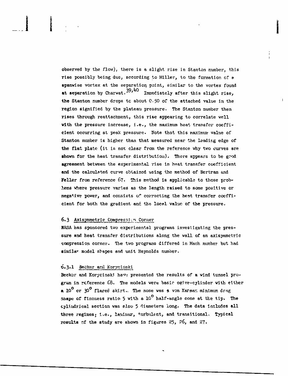
observed by the flow), there is a slig~ht rise in Stanton number, this
rise possibly being due, according t.o Miller, to the formation ofV e
spanwise vortex at the separation point, s~imilar to the vortex found
at separation by Charwat.3t~ Immediately after this slight rise,
the Stanton number drops tc about 0.50 of the attached value in the
region signified by the plateau pressure. The Stanton nuin'ler then
rises through reattachment, this rise appearing to correlate well
with the pressure increase, i.e., the maximum heat transfer coeffii-
dlent, occurring at peak pressure. Note that this maximum, value of
Stanton number is higher than that measured near the 1leadirig edge of
the flat plate (it is not. clear from the reference why two curves are
shown for the heat transfer distributioin). There appears to be g:.'Nd
agreement between the experimental rise in beat trannfer coefficient
and the calculsted curve obtained using the method of Bertram &ind
Feller from reference 67. This rietho6 is applicable to those prob-
lems where pressure varies as the length raised to some positive or
negative power, and consists or' cor-recting the best transfer coeffi-
cient for both the gradient and$ the local val'ac of the pressure.
6.3 Axisymetric Com ressi1_ Cornier
NASA has sponsored two experimental programs investkigating the pres-
sure and heat transfer distributions along the wall of an axisymmietric
iciupression corner. 11he two programs differed in Mach number but had
sinmilay mo:del sl'apes and unit Reynolds number.
50.3.1 BeC~k.r and Kor:ýinski
Becklir arid Korycinsk3 ha,-,, presented the results of a wind tunnel Pro-
gram in rcrerence (8. The models were basic- o~~ye-cylinder with either
It 10 0 or 30 0flared skirt.. The nose was *A von Kermar. minimum drng
wizapx of 'fincness ratio 5 with a 10 0 half-angle cone at the t~lp. The
cylludrical section was elzu 5 diameters long. The data includes all
three regimes, i~e., lantiwiir, +.urbiult-nt, and transitional. Typical
results -,If the study are shown in figu.aes 25, '26, and '2.

HMPAT TRNSE MOS~aIMTION
FOV& PUMM LAM IM6AtT. %SPRA-IONAT AN AMM1 UCP FL6Ž-XZýU.T ZtVCM~m
10* FLARS ___________
lo___ v4~tK> Wrrl40A___ ~P~ro,!
II. _ _ _ _ _
~ C.
FL.AIR6 JUMH~t ioN
AN DIES LAkkAtri 4ARMSOM
L~ VHEORYOF S7TUNE AJ4N -
4,4
AXCIAL 0%ShT4l6CE-,,)f/M-
FIGURE 25
77

HEAT TRANST17alOD
Am- AN V=3 rR-t St,%P
0.0mc .8 I-
0. 0 RD WEtGE. FlT- -
P3 CONE.--
Cl.-
VI~FLAE. JLJNC--ION
10.0 -- ]R /ER
---- VAN bRiES-T -TER uSING LENP5.0 OEF-r-40TEC PRE.SSURE.____
(NASA Ct'.LCULATiows)
STINE A1,b: WAILA'SS0
(D 0
AX(IAL c>MTANCE,, x/rc
FIGURE 26

ACT AN AU-S MMS.IC VLIktS.D 'S%"(AFTSVM ZMKI AN M~ a-OM K MM.
0-c0
0~
C~N.;c:. cF FLARE. JUN CnoTRAN svrtIOt
DN0VE-re~ P~tF5sul)Re(tHpSt CoýL.CL)LAIONS)j
-TURSULEt4RIP
T114EeR,? OF STIlNEAmWA~NLPLSS___
ly "MRSULS
AIA
FIGURE 27
79

For comparison purposes, theoretical calculations using the method of
van Driest69 and pressures corrected to account for the presence
of flow separation. The pressures used are defined as follows:
a. P1 is the pressure on the cylinder as computed by charec-
teristics theory.
b. PO is the estimated plateau pressure that exists for the
laminar ct _e and for the transitional case when transition
is near reattachmený.
C. P3 is the inviscid two-dimensional (wedge) pressure at the
flare body juncture calculated by starting 'ith FI oil the
cyli nder.
d. P3 was calculated by starting with the plateau pressure P2
and taking the flow deflection at reattachment as the flnre
body angle minus the inclination angle of !he "wedge" form-
ed by the separated region. In this case, the measured sel'-
aration 'wedge" angles were 30 for tl, 100 flare and 7f 0or0the 30 flare.
In calculating the heat transfer distribution on the cylinder, it
was ass•uied that the boundary layer started at the nose. The heat
transfer distribution calculaied for the flare utilizes the rcntticlh-ment point as the origin of the boundary layer.
6.3.1.1 Laminar Case
Figure 25 presents the data gathered for the laminar case. As can
be seen, the ex-reriis-tal poI.nts fcllow the theore' i cnl curve down
to the beginning of the interaction of the boundary layer wilh Ihe
pressure gradient. Immediately downstream of this point., the expcr'i-
mental values of the parameter St-V'RD drop to about one-half or ihe
attached value, then increases through reattachment to about 1/; o:*
the nose value.
80

At the beginning of the flow interaction with the pressure gradient,
the NASA's theoretical predictions (dashed curve without X's) Indi-
cate an increare in the heat transfer due to the increase in pres-
sure to the plateau value. Of course, this calculation is invalid
since it is based on van Driest69 attached flow theory while in ac-
tuality, this is the separated region; thus, the discrepancy between
experimental and theoretical values. At reattachment, the theoreti-
cal curve is based on P3 and the origin of the running length for the
laminar va Drest69 theory is taken at the reattachment point. This
results in tie curve labeled "lamlnar P3 in figure 25 and, as can be
seen, the theoretical and experimental valves appear to approach one
another.
6.3.1.2 Transitional Case
Again, the experimental heat transfer distribution follows the theo-
retical curve until the interaction point, as illustrated in figure
26. At this location, there is a slight hump in the heat transfer
distribution, then the experimental values of Stý/ drop below the
attached value at the separation points, although not quite to half
of it. This condition exists until transition takes place, where
there is a rise, this rise becoming steeper until reattachment Is
acccmplished where the heat transfer parameter is about 3.5 times
that at the nose. (Note that the flare angle in this case is 300.)
Comparison with the pressure distribution shows good agreement at the
separation point. However, the pressure data do not indicate the
abrupt rise characteristic of transition and do not extend all the
way to reattachment.
Similar theoretical calculations were for the transitional case.
Again in the separeted region, the theory ("iminar P in the figure)
based on the increased plateau pressure yields an increase instead of
a decrease in the heat transfer coefficient. Al the transition point,
the theory is shifted from laminar to turbulent, still using P2, since
there is no evidence of a preszure Intrease due to transition. This
81

~J. I
curve crosses the experimental points as they rise through reattach-
ment, but only predicts a value for the heat transfer coefficient of
about 0.10, the final. value at reattachment. The theoretical value
at the reattachment point based on Pt appears to agree quite well ex-
cept that it is decreasing with running length much faster then the
data. Thus, this method could lead to over-optimistic predictions at
points downstream of reattachment.
6.3.1.3 Turbulent Case
Figure 27 is for a completely turbulent mixing layer and may be di-
rectly compared to the laminar flow situation, since all conditions
are the same except 4he Reynolds number. The experimental data are
not complete prior to separation; however, the previous figures in-
dicate that there should be good agreement between theory and exper-
iment in this region. The value for St'RD begins to increase at
the beginning of transition; however, it is not a step rise because
transition from laminar to turbulent flow Is accomplished over a fi-
nite distance. This rise continues through reattachment t" a value
equal to that at the nose, this maximum occurring at maximum pressure.
The calculated heat transfer distribution uses laminar flow theory up
to the point where the beginning of transition was detected. Down-
stream of this point, turbulent flow theory was used. The theoreli-
cal attached flow pressure distribution on the cylinder was used up
to the cylinder-flare junction because the separated region was too
small to cause any gross distortions of the pressure distribution.
ev-Lr, the last experimental pressure point on the cylinder Is high-
er than the attached value, indicating that a pressure gradient does
indeed exist. In any case, the heat transfer parameter in the tronsi-
tional regime approaches the turbulent theory as transition tends to-
ward completion. Since the separated region is small, the position of
reattachment was not discernable; therefore, the origin of the running
length was taken at the flare-cylinder junction. In this case, the
theory and experimental points appear in fairly good agreement,
82

converging to thl same value downstream of reattachment. The theory
used for the flare in this case was based on the attached flow wedge
pressure since the flow separation "wedge" angle could not be defined.
6.3.2 Ferguson and Schaefer
Ferguson r ! Schaefer 7 0 have presented the results of an investigation
very similar to the preceding one, the main differences being the test
Mach number and that a cone-cylinder instead of the ogive-cylinder was
used. Also, only the pure laminar and transitional cases were
investigated.
Figures 28 and 29 are from this reference and, as can be seen, there
is no decreas2 in heat transfer within the separated region for either
case. A possible explanation for this in the transitional case is
that transition occurred very near the separation point, thus Pro-
ducing a much more energetic separated region. The reason no decrease
appeared in the laminar case is not apparent. The pressure coefficient
on the cylinder is zero in figure 28 because of a fault in the experi-
mental apparatus.
In both figures, theoretical calculations are shown. The solid curves
are Douglas calculations by the theory of reference 69, and the dotted
and dot-dashed curves are NASA calculations using the theory of refer-
ences 71 and 72.
In figure 28, the laminar van Driest69 theory compares wefll with that
of Reshotko71 on the cylinder up to fhe Junction. On the flare, the
NASA calculations take into account the pressure gradient, hence, they
show an increase in heat transfer rnefficient with ruwining length,
whereas the constant presswoe van Driest calculations show a decrease.
In both cases, the running length Is taken from the nose. It Is inter-
esting to note the temperature labels on the two -NASA laminar curves.
The present authors feel that there has been a misprint and that the
labels should be reversed since the Stanton number decreases with in-
creasing wall temperature (see reference 69, figure 6).
83

PRES5SUREF. COl.FF1CI'SNT A~Ntzý-ASAT VTRNNSFER tDST1R~sY11'N
FOR~ Ab LAMINARM SLPAR~A~TON A-TAW4 AYI-SOYMM~iTRIC 1zLt\R~L SKIRtr(AFTER ý:EIGUSEOON AWCý SCHA'E.CCR-REV7IO1)
0.2. - .~- V
-*COL -- cfCOE
4 z, cW>E:
C.
IFLARE JU CýTION
t4ASA CAt-CU%..P7I0NS ___
rurzaUL.ewr -re4QvO( T-A-li
7- CRE-F.7 H2 ASeX CAL-CUL"ICýN%
4I)ii) VAN t~ST ____
iLT C-ruraibu r)
0.? .W- 4WSE! r~
~- I tL.-
40.2ý4 "0

PRESSURE CoevC-4TZNO AINDHEAT TRAWNPEER -i VZ C-UTtON
FOR 7RANSITION!L SE¶?WTIN ArtTAN AISYMMAUTRI FLARED 51iP-.(A'FTER 17E.RG,~ ANtZs SCHArFek, REF. -70)
__d
IL riv
00
Ju~c~nc"(Zr .. JuNC. I N
2. tIASA C1LgAVIN
I 6
0-.,QVI
4)
Liik 4 -kca3
OR S;~~4 WWI -'r i5

I
in figure 28:, downstream of �epsretion the 1.aminar theory arpe�rs to
h� ic1 vslid and. the t�rbuleuit theory based on the £�i�se� as the running
leiigtki oi�igin (solid lines) �re�icts a value low by about 1�.O per
cent. The turbulent theory calculations with ruzmir�'� length from
the c�ylind�r-flare junction appear to give b� �tc� agreement with the
data.
Similar cc��nts apply to tigu�-e 29.
b.3.3 �
lJhen the ?lo'�i is tw�b�.zl�t &t r�mpresiio�, appJ�y'ing rt�rni� �c�gt�i
iwditi�tions �o turbulent theory ipj'eare� to p�edi�t mxLrdx� vsiues
of that ore c�lo�e to t� ecperimemt�2L uata e�v showr� � Vig-
rnes � 20, and 29. ?Id�ti�ng c�ta fr� these two references (68ix�4 703 v&ri7y th� � AXaQ, i�il� it is i'eadily diseern'.
iXule &�u thsae datd tl'M, ror turbulent flow, the maximuiz value of
8t increases �4tb �nc�e�sin� flare ar�gI.e, it is not evident how
a �ie*� tranai�i' ;arem�ter variem Ath Mach and RoynoldG number at
� � �tle'�ticz, s�le. tiit'i'i tUs 3Ai�er fact in mind, t�e �eaent
�t%�L� �nn�tru�t�d figu.�-* 3(�. by plotting the max1m�i e�eriment�.
value� of� �nt�i r�u.�b�r at tta�hmet�t, div-id�d by the theorctical
� of t� � tiumber th�t �,ould e�iist at th�& �oir�'t aceording
to �ix� � �f r�erenc�, �9, �rsu�s the z��a�dinurn e�'p'�vimerital value
� t� �r*�- � �-2Z� � .i ise fr� �eparat1 .' i through �et�t�hrnent,
This ft�yr� i� i� � t�cn C�e6 '�'e�e1�i repres�nt&U ye a�nee th�r�
�* only & fe� �at� po1�to. �t s�c� � b�::�-� t �. �he
� rtc� �az�e� The dep'r�ure of t.� �ta�ite:� nui�z�
� Ve the�r�t1'�al value ir��s.
�. F(ir hmb�r flow, tI� incrca�t� c'er the th&t'r�,ti �
cr). attached 1Vw v�lue at re�ttachx�ent can be significant,

I
V t A1tj 2
PIZ
101
WE
r J1
i~ileg
.0w

however, further data are required to define the Reynolds
and Mach number dependence of this parameter.
b. For turbulent and transitional flow, the St V•C increase
over the theo'etical attached flow value at reattachment
is significant. Also, the maximum value of St'D appears
to correlate with the maximum overall pressure rise; how-
ever, further data are needed to better define the Reynolds
and Mach number effects.
c. Use of attached flow theory and a foreshortened running
length does not adequately describe reattachment heating
for laminar flow. Turbulent flow data give better agree-
ment with this modified theory. This poor correlation may
be attributed to the lack of knowledge of the boundary lay-
er thickness at reattachment. It would appear that for
laminar flow the boundary layer is thinner, but definitely
not zero since the rise in St/F is slow and there is no
sharp peak. In the turbulent case, this thinning is much
more pronounced as evidenced by the sharper rise and higi'-
er peak value of the St F- in figures 26, 27, and A:8.
For the present, it appears that for laminar flow using
the reattachment point as the running length origin will
give conservative results. For turbulent flow over moderate
flare angles (< 200) the cylinder-flare junction may be used
for the running length origin, while for larger flare aneles
t•he reattachment point should be used.
6.4t Shock Wave Impingement
Of the two types of impinging shock waves noted in Section 440.2, only
ihe oblique type will be considered in detail. The swe'pt planar shock
interaction hre not been investigated extensively; therefore, the
trea~ment selall not be In great depth. Discussions are limited to
tur'u=ent boat.,ary layers ainee only data for thia regime are available.

I
6.4.1 Oblique Shock Impingement
There have been two extensive programs for the investigation of the
beat transfer in a separated region generated by the impingement of
an oblique shock on a turbulent boundary layer, one by Douglas Air-
craft Company and one by North American Avia.ion.
6.4.1.1 Douglas Study
The results of an Air Force funded investigation by the Douglas Ad-
vanced Missile Technology Department are reported in references 45,
73, and 74. The impinging oblique shock waves were produced by
wedges of various half-angles, and hence were two-dimensional;
however, the boundary layer generators considered were both two-
dimensional and axlsy3.,netric. By varying chamber conditions and
"-iedge igle, a wid. range of shock strengths, Reynolds number and
Mach aumber were Pttained.
6.1*.1..1 Inpingement on a Flat Plate
F9gure 31, which is from reference 73, shows some of the pressure
end heat transfer data gathered using a flat plate as the boundary
2.ayer generator. As can be seen, the pressure distribution exhibits
a very definite inflection point; in fact, it is almost a plateau.
This is not unexpected since the shock strength is high, thus giving
a large selparated region; at lower shock strengths this plateau de-
generates to an inflection point. The heat transfer coefficient in-
creases fram the undisturbed value to a higher value in the separated
region where it appears to remain constant. Further downstream, the
b~est transfer coefficient increases to a maximum value at reattachment,
then begins to drop back to the local zero pressure gradient value.
S-te that tte maximum value of the heat transfer coefficient is about
4.5 times the attached zero-pressure gradient value prior to the
iaiterecti on.
The distribution of the ratio of recovery temperature to total tem-
Wrature is plotted in figure 32. The variance of this ratio can be
89

OBLIQU2 SHOCK IMPINGZEzME.NTON A -TV~o-t~iMF.NSloN~L-
TURBULENT BOUNDA~RY LA4*YER(AV=FTSP SMYANO, BAUSCP4 A~tb bO>NNELLY REE 13)
SMOCK GPENERAMOR A&NG~LE -
FREE.S'TRE-.AM MACH- NUMS-F~-f
0PRE ssso~ RA,-TIO., pAp*
0
0
A
V 0 AA
A
PLA-MAU0
OA
LDisTANCEE, % -INCI-4eS
FIGURE 31

0iz•
0 0~ 044 0
I. •
So to. F'I
dooO(P
010
FIGURE 3291

Il
due or.ly to a variation Ir. recovery temperature since total tempera-
ture is a constant. As can be seen, this figure indicates a recovery
teriperature about 3% higher than the VPn Driest value in the reattach-
ment region.9
6A•.1.1.2 imingement on a Cylinder
Figure 33, from reference -(4, presents some of the data gathered with
ari axisiynmetric bondary layer generator. These data were obtained
at nearly identical conditions as those above, the only difference be-
Ing a slightly higb,'r stagnation temperature.
Camparison of figure 33 with that for a flat plate (figure 31) reveals
that the overall preecvste rise is greater in the latter case. This is
reasonable since e favorable pr,.ssure gra.ient exists around the cylin-
der trom the shock impingement point; thus the fluid may escape the
pressure rise across the impinging shock by flowing around the body in
a cross-flow pattern. This reasoning also explains why there is cnly
incipient separation on the cylinder (as indicated by the very slight
changes in curve slope) as indicated while a rather large region of
separated flow exists on the flat plate. The other data from these
references also indicate that when both types of boundary layers are
subjected to the same overall pressure rise, under the same free stream
conditions, the separated region for the axizynmmetril case is always
much less extensive than that for the two-dimensional case.
-the heat transfer eoefficnt distribution ILDowcr +he pressuie curve
as it does witb the fl-,. plate. A change in slope apJiara to uvcur
at approximately the same locrntion t thai. in the pressure distribu-
ticn. 'ownstream of thJs s.lope charge, the heat transfer coefficient
inerr,'asen. ,.o e mayimam of between 3 and 3.5 times the undisturbed
value, ther. decreases to the local zero pressure gradient valte•
The recovery temperature shows similar characteristics only not Co
pronounced as for the flat plate boundary layer generator.
92

CIONSL IQUF SHOCK IMFiNGE&MISNTON AN I-SYMMETFR1C TURBULtirW
BOUNt:)t4-RY LIAYE(AFTER SA,ý*eNO NTB A~USCR REF.74)
5;-oCK OE-t'U.RAToR, AN'GLE. -
0 0.~
(AA3T
0i IN ______ A.
A M-k "ANSS
FIGU E$UR E 33Tc~p~
93

6.4.1.2 North American Avietion Study
Reference 75 presents the results of a Navy funded study performed
by horth American Aviation. The model consisted of a two-dimen-
sional shock impinging upon a flat plate. A row of orifices was
placed near the leading edge of the plate leading to a plenum cham-
ber in which air was stored, This air could be injected into the
boundary layer to thicken it and/or to initiate transition.
The data from this reference show similar qualitative characteris-
tics for both the pressure and heat transfer distribution; the same (trend of correlation between pressure and heat transfer also is evi-
I
dent. The increase in recovery temperature in the reattachment re-
gion was found to be similar.d
4
6.4.1-3 Correlation of Pressure and Heat Transfer
Sayano has presented in reference 45 a compilation of the data re-
ported in references 73 and 74. In one of the figures he plots
maximum rise in heat transfer coefficient against the maximum rise
in pressure. Ibis figure is reproduced in this report as figure 34,
with additional data from reference 75. As can be seen, there
appears to exist a definite correlation between the rise in heat
transfer coefficient and the rise in pressure, from which the follov-
Ing relation was determined:
where h and Po are the heat transfer coefficient and the pressure
existing just prior to the shock wave interaction, respectively, and
Q iG the slope of the curve which mty or may not increase with in-
creasing boundary layer thickness. Combining this with a correlation
between the measured maximum pressure rise and the theoretical pres-
sure rise across the Incident shock gives an expression of the maximum
heat transfer coefficient as a function of theoretical pressure rise
94

i l
-iiLd Ul w w wCD 01u y Ity ! 0 WX W 1DdGoo
3:~ W~
wZ Z
j0./99f 1W
LLCD0.
0 0 Z i
wd 4~ X
FIGt;RE 34
95

,cross the incident shock gives An expressivl of the maximum )Leat
trm.nsfer coefficient us a Punction of theoretical pressure rise
(pl/C), a-rose the incident alock2 of the ftollo-ing form:
where N is the exponent from
NPmax ,pl\
Frm reference 4 5 , H. 1.75 for •< M < 4 and 7.95 X 10⁶< R/ <2.56 x 10o.
It should be emphasized that these correlations are strictly represent-
ctive of a trend end should be userl in any design calculations with ex-
treme care since the exponent appears to be a function of the boundary
layer thick-rnss. Further discussion of extending the applicability of
thia cvrve is contained in Section 8.
In s•zz•s•y, both the Douglas anu North Arierictn inve.;tigations have in-
dicaited that shock impingement on n turbulent bonmd&rv layer can result
in excessie heating at the reattachment point. It is also evident
that the rise in heating for the axisymmatric boundhry layers is Jess
aeverethan +.hat for m two-dimensionel boundary layer due to the exls4-
ence ot the cruss-flow.
The maximrz heat transfer coefficient appears to correlate well with
the theoretical inviscid pressure rise across the incident shock wave;
howyer, further data are needea tc accurately define the effect of
boundary layer thicmness.

I
6.4,2 Swe21lnurSock Lm~ingement
In reference 7ý, Mil.ler, et a4 report the rercIts of sn irvestigation
o tht interaction of a surface boundary layer wit-h a shock Vve pro-
Auced by the leadirg eCge of a fin perpendiculý'r to the surface, The
:uthors of to•is referent, do not state flow _-.Vradton actually
oc=o but the heat transfer distribution shews a significant rise as
seen in figure 35.
6.5 Rearward Facing Steps
There have been two recent imiestigations of the heat transfer distri-
bution in high speed flow aft of a downstreem fa:in6 bte;. One by
S. L. Strack at Boeing Airplane Company, rept.rted in references 43 and
TT, and one by A. Na~smiih at the Royal Aircraift stabiilshmznt (Britain),
reported in ý*-eferences 78 and 54.
6.5.1 Boeing Study
In references 43 and TT, S. L. Strack of Boeing report-, t•, results of
some rather recent experimental work performed to determine the heat
transfer distribution aft of a downstream facing ste:p. The Mach num-
bers were nominally 3.0 and 6.0, and the boundary layer was turbulent
prior to separation in all cases. The model vas such that a range of
boundary layer thickness to step height ratios of 0.12 to 1.2 was pos-
sible. Figure 36 presents two cmuves that are representative of the
Boeing data, differing only in Mach nimber; i.e.,the ratios of boundary
layer thickness to step height and the free stream unit Reynolds number
c•e neorry the same. The ratio of the experimentally determined heat
transfer coerfluients under separated flow conditions to those deter-
m1ned for a flat plate are shown as a function of axial distbnce Tea9-
urd in step hbeghts. As can be seen, ilhc t,-o , 1iffer quite
signiftit.ntly. -From the Mach 3 data, Vihere zppears to be &bout a 3C p6? :int
increase in the heat trwsfer in the reatta'.e.=-.nt region. This per-
centege increaso decreases with increasing t-=undary layer thickness
to step height ratio. From ,tbe Mach 6 data, while there appears to be
a peak ir, the hert transfer di.stributionj this peak has a maximum vsluc
91,

PLANAR %&lS`kV~IC WAVE.kl4TSRAcT1C.*)V4 WT
TWO-tAMENSIONAL PeUNCýAkRY LF
VrZ I -
-GO~f
2
C,ftl. O.Za .3 05OO.Q irO 's Lo 1.1 .a tA .
FIGURE 35

I4A
tj
4 D
Ir
Z4(0
"3e*UP 3AS -
IAWR __

tVhat is less thekn the value that. vould exist at that asne point on a
flat plato. TAiG p~k is tolleved by a dip in the curve and a subse-
quent increase that eppear, to approach the flae riatc "vEiue. The
shape of these distributions and the fact ihut the f1aV SIat'a value
of heat transfer cc-wffticent was nowhere exceeded for Mach number
equal t: 6 vas evident in all the data.
Frm the Mach 3 data it ararid that the maximum heat transfer occur-
red considerably downstream nr the impingem-nt point of the dividing
streamline. The impingemert point was dctermined by using standerd
oil flo'w techniques. Howevar, the loeation of maximiam heat transfer
wa; fourid t occur upstream of the polzit whexe the pressure had re-
eovored its flat plate value. This latter Irend vas evident from the
Mach 6 dh,& also.
6,512 Naysmi~h' Work
Waysmith hier reported zome experimentel. dr1r1 in r xfereices 54 an- 7P
on tbe bea.t transfer distributlon aft o& a dovnstreem facing step for
both i tvo-dimcnsional. and &; axlsymetric body. The two-diensional
mede3 et•issted oZ a wedge placed on top of a flat plate, and the itxl-
syvrz etric model consisted of a cone-cylinder -rith the base diameter of•
the cone exceeding t%;. diameter of tha cylinder The boundary layer
vas turbulent for thU two-dimensional model and laminar for the axi-
symmetric model.
Figure 37 presents the data resulting from. the above experimental in-
iestigatioa for both configurations along with some free-flight data
reported in reference 79 obtained on a model very similar to Raysmith's
axisy~metric model. lHowever, these free-flight deta were obtained wi h a
turbuhnt boundary layer prior to seljaration, whereat the data from
Naysmith for this configuration uere for a laminar boundary layer up-
stream of the separation point.-
The data indicate for a itminar boundary layer upstream of the separa-
tion polr.t there is a drop in heat transfer coefficient behind the step

1131
190
Im;
ILI
00

then a rise to a peak value of about 3 times the heat transfer coeffi-
cient at the cone shoulder (separation point). This peak is followed
by a subsequent drop that appears to approach a value of about 2 times
the value of heat transfer coefficient at the cone-shoulder. The rea-
son for this rather high value of heat transfer coefficient downstream
of reattachment was that transition occurred after separation (this may
also be the reason for the rather high value of the ratio of h/n 0 at
reattachment).
For a turbulent boundary layer there is no evident peak in the data,
which was probably due primarily to the heat transfer instrumentation
being too widely spaced to pick up the peak. The data for both models
appear to a&7ee quite well. Note should be taken, however, that the
data are normalized by the heat transfer coefficient that exirsted at
the cone or ramp shoulder. This value is much higher than the flat
plate value that would exist along the plate. Thus, the fact that
downstream of reattachment the ratio of heat transfer coefficients is
less than 1 does not necessarily indicate a low heat transfer coeffi-
cient. In other words, the heat transfer downstream of reattachment
may still be greater than an equivalent flat plate value.
6.6 Stmm~ary of Results on Heat Transfer
a. The heat transfer mechanismc may be strongly dependent upon
the state of flow:
(1) For laminar separation, the transfer properties of
the mixing layer appear to control the heat trans-
fer to the wall.
(2) For turbulent flo-is, the continual flushing of the
wall. with new fluid from the external flow may con-
trol the heating.
(3) For transitional flows, no conclusions can be drawn
due to lack of data; however, the location of
102

I
transition relative to the separation and reattach-
ment points will probably determine which of the a-
bove mechanisms would predominate along with the
degree of flow steadiness.
b. From the above, it is logical to state that the distribution
of heat transfer will also depend upon the flow regime
encountered:
(1) For laminar flow, there is sometimes a rise in heat
transfer at the separation point due to the existence
of a separation vortex. Downstream of this location
the heat transfer will generally drop to about 1/2 of
the equivalent attached value; however, if the sepa-
rated region is smell, this drop may not be severe, and
in fact may not occur at all. Aft of this minimum,
the heating increases throughout reattachment to a
value greater than the lamInar attached flow value.
(2) Transitional flows do not exhilit so proxicunced a
minimum and may, if transition is close to the separa-
tion point, exhibit no drop in heat transfer within
the separated region. At the transition point, the
heat transfer begins to increase and continues to do
so throughout the reattachment region reaching a maxi-
m= value which may be greater than either the laminar
or turbulent ettached flow values.
(3) Turbulent flows generally exhibit no drop in heat
transfer due to the energetic separated fluid and
small extent of the region. The rise throughout re-
attachment region is rapid and the maximum heat trans-
fer is of the same order of magnitude as that near the
leading edge or stagnation point.
103

c. The heat transfer distribution appears to be dependent upon
the oneoming boundary Layer thickness:
(1) For lambinar sep-uxrtion, the local heating would de-
crease with ircreasing mixing layer thickness (pro-
portional to boundary layer thickness) if 6.6.a.1
is ecrre•t however, the data do not indicate that
this dependence exists.
(2) The deata definitely indicate that the local heat-
ing for turbulent sepbration increases with increas-
ing mixing layer thickness if the mass exchange gov-
erns the transfer of energy from the free stream.
(3) For transitional beparatiors, no remarks can be
wiade.
d. The above statement (c) mry also be applied to the average and
total heating rates. The turbulent data definitely show a di-
rect dependence upon mixing layer thickness, whereas, the
laminar data show no dependence.
e. The data indicate, at lepst for cuvities, that the total heat
transfer frcx a !umina- mixing layer Is about one-half of the
attached value. The value for turbulent mixing layers may or
may not be les than tc at ached valuel depending upon the on-
coming boundary layer t'4.lckness.
f. It is felt that thre6edomef.voi ieotri.'s wll generally
suffer less severe heating at rzattachiuen, if the P.-Cstliti--
of a cross-flow exists to r(tieve thc high %r!,S.2re at
reattachment.
g. The recovery temperature may increase witl'in the sepsr9ted re-
gion; howe*er, more deta sreneeded to rerify this observation.
104

I
h. The use of a modified prssuye ard a forc--e- running
length with attached flow theory for calculating the heat-
ing rate at reattechment can lead to the following errors
unless extreme caution is exercised:
(1) grossly conservative results for laminar separatlon,
(2) optimistic or conservative results for turbulent
separation, and
(3) erroneous distributions downstream of reattachment
that can give either optimistic or conservative
estimates.
i. Thero appears to be a correlation between the maximum pressure
rise and the maximiun rise in heat transfer coefficient for axi-
sy=netric cumpression corners and incident shock waves when the
flow is turbulent.
3. More analytical and experimental work is needed to determine
the natures of the separated flow, boundary layer downstream
at reattachment, and of the mixing layer.
103

7. CONtCLUDING REMARKS
The problems associated with flow separation in high speed flight
are qualitatively under-taood. On the other hand cour quantitative
knowledge of the subject, borh analytical and experimental, is de-
ficient due mainly to its lack of generality. The purpose of this
section is to synthesize the information in the preceding sections
and to point out area where further knowledge is needed.
1.1 Veriibles Des:rlbing the Problem
Separated fLows are appropriately classified according to the state
of flaw, I.e.,, whether the f>.w in the separated region is complete-
ly laminar, completely turbulert, or whether the flow undergoes
transition betweer separation and reattachment. The main variables
governing the nature of the flow are free stream properties such as
pressure, temperature, density, viscosity and velocity and also the
geometry and thermal nature of the surface being considered. Once
these factors are stipulated, the behavior of the flow can be de-
scribed by three variables; namely, Reynolds number, Mach number,
and fluid to wall temperature ratio. The above factors may be con-
sidered the pertinent independent variables for the problem of sep-
arated flow.
The Information required when considering the problem of flow sepa-
ration in vehicle design is:
a. when and where flow separation will occur,
b. what the extent and shape of the separated region will be,
c. what the pressure and heat transfer distributions through-
out the separated and reattachment region 4ill be, and
d. whether or not the flow in the separated region will be
steady, and if not, what is the nature of the unsteadiness.
107

Ii
Tnese latter t dictatl the devendent variables which must be
considered. 7•,,e Aepend-rii variablea arc not only functions of the
4indexendei.At .,axvinblec but, es in most reai processes, they are also
interrelated, 3=aS ,f the more pertinent dependencies are:
•• e.etent of the separated region is of substantial de-
ei* im prtrmce. tie quamitities of primary interest are
the selaration and reattachment points and the slope of
the dlividig streaimline. These quantities may be directly
determined experi entr l b,, by mneasurement of the skin flric-
tion, from op-icel measurements, or from the presiure dis-
tributiou. "nalyticaily, the separation point and extent
of separation ae-e dependent primarily upon the magnitude
of the pressure rise causing separation, geometry of the
body, state of the flow, wall to free stream temperature
ratio, and Peynolds and Mach numbers prior to separation.
b. Pressure Distribution
The pressure dist-ibut ion i s a function of e3sen! ,!lly ihe
seare variabLes listed above for separation geometry; h,-,oe,
It is A•laily a dependet variable. If known, however, the
pre:,sure dis-t-bution is very useful as a dependrnt variable.
Thi has proved to be a quite power.' ool in separated flow
analysis since the pressure distribl.tior is probably the most
simple experimental measurerreni to mLY,- A Knowledge of the
pressure distribution itself Fio'Q3 -a ,ood deserlp.t!on of
the extent and shape of the sep?,,..tiii reglin. It .-oa a`-o be
used to predict reattachment heating rales 4 hroigh correlation
criteria. Sim!Thr l •cir mes can probsbly be used to predict
skin friction also. Obviously, the pressure dis;,ribu-ýion Is
of utmost impo.'-ice in ascertaining any pert-batiohs tu the
ledi distribu[cn nr dr&g characteristics caused by flow
separation.

C. Heat Transfer Distribution
In order to conduct a detailed design analysis, the local
heat transfer coefficient, recovery factor, and initial
vail temperature distribution must be known. Certein stud-
ies have shown the recovery factor to be relatively con-
stant throughout the separated region and approximately
equal to the attached flow value. Since the initial wall
temperature distribution is known beforehand., the local
heat transfer coefficient is the main unknown to be deter-
mined in order to complete the .alculation of the heat
transfer rate. The major flow parameters influencing the
local heat transfer coefficient throughout separation and
reattachment are the boundary layer thickness prior to and
at separation, the rate of growth of the mixing layer, the
mass exchange between the separation cavity and the exter-
nal flow, and the boundary layer thickness at reattachment
"and during redevelopment after reattachment. A knowledge
of these parameters appears to be of fundamental importance
in establishing an accurate analytical model for heat trans-
fer in separated and reattaching flows.
d. Steadinaess of the Flow
One of the properties of separated flows whose significance
is often overlooked is flow steadiness. The stability of
the free shear layer is inherently comnected with the state
of the flow and extent of separation along with many other
flow parameters such as Reynolds number, Mach number, and
stream to wall temperature ratio. Of primary importance for
design purposes are the magnitude and frequence of the pres-
sure fluctuations within the separated region, the variation
of the extent of separation due to the fluctuations, and the
detailed behavior of the fluid in the viscous flow region so
that shear and heat transfer trends may be predicted.
The problem of separated flow is thus defined.

I
7.2 Solution of the Problem
There are two approaches for solution to any engineering problemi
namely, analytical and experimental. In many cases, a direct an-
alytical solut~on is sufficient due either to the simplicity and/
or lack of significance of the problem. Unfortunately, viscous
flow separation Is an extremely complex problen, in fluid motion
arid its effects cannot be indiscriminately ignored. To daic, no
analytical model has been developed which lends itself to an en-
tirely satisfactory solution. On the other hand the scope of the
problem Is so vast that a complete experimental description of
the problem is not practical. Well balanced anal.ytical-experimen-
tal approaches appear most rewarding, although recently purely
theoretical advances have made some gain In the area of laminar
separated flows.
7.3 Present Status of the Problem
AC-ditional work is needed in all areas of investigation of scpar,'AUd
flows, particularly in the higher (hypersonic) speed range. Soine
areas whiich yet warrant special attention follow:
a. Analytical
(1) Most of the more sophisticated analytical approaches
are centered around the use of the boundary layer equa-
tions. However, it is known that strictly speaking,
several of the boundary layer assumptions may be vio-
lated by the occurrence of separation. The Importance
of these violations should be definitely established.
(2) The better theoretical and semi-empiric•.t] analytical
methods should be generalized to include the heat
transfer, real gas effects, and hypersonic Interaction
phenomena.

(3) An analyt1Ja2 eriter4n for the stability oe: 'he sepa-
rated shear layer ahoulA be established and tested to
assist in the de-erinination of vehicle dynamics.
b. _ESrimental
(1) Addlticmnl experimental research Zor piessure and heat
transfer dl .tributions is needed (escciFcLly ýn highbr
Mach number ranges, M>4) for most geomtate:1.E- and for
both laminar and tur-bulent flow.
(2) A detailed knowledge of the behavior of the flow in the
free shear layer, visccus separation region, axA re-
attachment zone is needed not only to have a beter
qualitative muderstanding of separated flow, but also
to provide correlation parameters for semi-empiricel
analytical efforts.
(3) Additional stability data are required, primarily infor-
mation which establishes the conditions under which os-
cillations will occur and the nature of the ressultant
oscillations. A detailed understanding of the inter-
relation of the parameters giving rise to instabi.ity
Is also needed.
•N) he importance of three-dimensional effects, eapeo-:'tlly
those which occur on supposedly two-dimension'A3 geome-
tries and which would not be accounted feir in a 1wo-
dimensional analysis, should be dete=ined.
The foregoing cumnents point. out only a few (those felt to be most im-
portant) sapects of aep r&W flol-s requiring detailed attentlon. Ob.
viously, a grett deal ot vork i.s yet required to provide the design
engineer with aufficient tools to hondle the goneral prIolem.

0.LIST OF REFEENCES
1. Prandtl., L.,, "IJber Flusslgkeittzbevegung Eei 3ehr Kleiner Relbung",Verhand1lingen Des Dri tten nl ernat ionalen Matheuiat! kar Kongresses,Heidelberg: 484-491, 1904.
2. Vatmyhin,. k. lk., "Op~ the Separation of Magnet~ohydrodynwniv Bound-ar Layv"., joizal ofA_A 11 3Pd Matbematics and Me ch anics , Vol. 27.,
3. c-iig H., _BMm ýeer Týo~ (54Th Edil Lon'. McGraw 11111P4* Co., -1m,, lse-v Yorx', l196".
11. Crocco, L. Rrd 14. leea, "A Mi~xing T1-ec~ry 1ýr t' Inte~ractic' Be-tween Dissipati~ve Flows "n IVearv Isenrxtopie Stre~ams' *4ourni3. of.he keronauttical3c'.enceo Vol.. 19, fin, Vi: 64V6-16 Oictober 11952`l
5. Crocco, L_. "'Considera~vrms on 1tlke Shot-k-BowuýiPxy L-7)er Interact ion",P*roceedins on t!,e cofon " SdArnai3 ". f5tPolytechniC :Instltuttt or &7ookc'yn., fiz~ York, 1955.
6, ZTheng, S. I. and L~ D. Chemg, Onthe Mixing Theory of' Crocco .qndLees and it6A~pplic~ton to Shock Wave-Laxrdnaz: 13ouneqrX Layer Ii'.-tereet'io-% - Parf1. II, Princeton Unf-ve--ity Aeronw~tdcal Engineering
T. Bray, K. N. C., G. E. ('-p4d, #&nd M. Woodger,arocc'o - Lees and Othe~r Y1Žtbods ol' Tn'ýrs;ior.n .~~&.~and Laminar. BouderyE Layrer -nl-syrd Suction, Azronau-ci~a& Reitrc Cotaci Ekr,ý,~,937t
8.Glick: H. S., a~idMxig11,er fo Zvperza '-rated and Reatýtach~in~fjls, Gu~ggenhieim Aeronautical LsQtoraxo,Califo'rnia Institute uf Techncogo~y, By-personic llnearch PeoJect,JMemoraridum NIo. 53s May 1960.
9. Les L.9 and B. L. IReeved, Suesn;cSprte n etahwLaminar Zlows: 1. General Thtary arld AUlicatln to Adlabat!<,&cwdary Layer-Shock Wave Tnteractions, AIAA Prepr-int N~f. 64-,
AMAerospar-e Sciences Meeting, New York, Nev York, Zrwnue.ry C"O-.,"Z1964
10. Wwrit~s, Zi>, '"Ap'tuximte Calculatior. of' the Lrminar Boundetry Lz-ye:-'.Aeronautical_(ýate~r1. 17ol. 1ý Part 111: 245-2%., Nweemter 1950.
U. Cmrle, A. ani $- Skan, "Ap?roximate Methods for Pred! cting Propertiesof La~iaur Bour~dary Leyers", Aoronautical Suaterly, Vol. 8, P-ert 3:257-268, 3 $57.

.LST OF RV'RENW~ fContinued)
3.2.. Lichmann, G. V., Bouindary Layer and Flow Control, Vols. I and IT,Rargzý-n'i Press, New Yo-rk,19
13. Maskell, E. C., Flo Searation in niree-DiL,,n $on. Royal AircraftEstablishment, Report No. Aero 2565, London, Engleand, ~vm~ 95
l14. Oswatitsch, K., "Dije Ablesiungsbedingung -'oaa G'enzachict':n,Soriderdruck aus GronzschcklctforschunE", 2Lp. 357
August 1957. fý
15. Sears,. W. R., "Bourndary Laý-ers in Thre, -Dime rs i ol Firv", AUfeMechanics Re,4ev.s, Vol 7, 7> : 281-285, July 195ý.
16. Moore, F. K.,, "kthree-Di-mens ional Boun~dary Layer Te'yA~ivsrcesin Applied Mecha,-;I.!r, A-C!-detiQ- Press, in,:., Nlew York, 1r-9_5 97 _T)95,6
17. Om~an, R. A., The T1hipe-Dirnensiornal Laminar Bonnv'ayLL.aver Alonr.ý eCorner, Sc-fl. Th1esis, Massachusetts Ins~k.41ut.e of Tectnnolc-y (~AGTIA2U?-12i6), June 1959.
18. Cooke, J, C., and M. G. Hall, PRindetry Layers in Th~re'!-Dinentzi:ns,Royal AArcraft Establishment) Report No. 2635, 0D2'35731, London,FrgIln'j 1951.
'L. R. Meckic', anZ D). Wezs A Rleview of Hyperýionlc F'low p 4r.ob6M Control ý-haacteriptiý,c, United States Air F'orce, Aeronauticalje~sTR 6ýI8 Mcrch 1962.
20J - --e E. S., Wise P'ressure htS ~ o 1- ixeds en T--.-DimrnenonalAirfoils and on Bolao Rvl-to di 9o W ~1.F~s Vi11Turbulent Boundary Layers, N,,WCA N3QOlc- J~ntmry It)"(.
21 Ferrari, C.., Airfoil Pressures al SuT-_.rcioni:_,Scqý Un(;C~r rct?low' Conditions, Applievd Physics L:M'~ kp,liniverc-ity, Atigu~t 1'Y
22. penlsonf M'. R~., and F. Ba&-x, -Compres- b½ IYý S i-'sr Layvr VI! 1, ,
Februpry 1()63,
3.Baum, E., Erffczt of Bun~r o-e ldn -n 11ji, Lwrinr_____ ~r cShear Jayer, 7l~i-ztcl~op1ilcal ;Yrtlems, No~v1t. No~(, <)$ 1"'il
24. Ki nj 11, H,t sind E. Batwij ninhalrp;: and ;~onm Profilet rin Ox' L~imnhii
Morch 19u-3.
114

I
LIST OF REFERENCES (Continued)
25. Reller, J. 0. Jr., and F. M. Hamaker, An Experimental Investigationof the Base Pressure Characteristics of Nonlifting Bodies of Revolu-tion at Mach Numbers frr 2.73 to 4.98, NACA TN-3393, March 1955.
26. King, H. H., and E. Baum, Effect of Base Bleed on the Laminar BaseFaA Electro-Optical Systems, Research Note No. 10, May 1963.
27. Baum, E., Effect of Bondary Layer Distortion at Separation on theLaminar B~ae Flow; WE.ctro-Optical Systems, Research Note No. 16,October 1963.-•
28. Korst, H. H., "Ccrments on the Effect of the Boundary Layer on SonicFlow Through an Abrupt Cross-Sectional Area Change", Journal of theAeronautical sciences, Val. 21, No. 8: 568-569, August 195T.
29. Korst, H. H., R. Ii. Page; and F. E. Childs, A Theo-z for Base Pres-sure in Transonic Frt, Supersonic Flow, University or Illinois, M4EIl 392-2,- 0GB TNi 55-E:11arch 1955.
30. Korst, H. 1i.., "A Theo-ry for Base Pressures in Transonic and Super-sonic -F.&ow', Journal vr A Ied Mechanics, Vol. 23, No. 4: 593-600,December 1956 .
31. Kirk, V. N., An Ah a-oximete Theory of Base Pressure in Two-Dimen-eio'al Base Flo'r at rsonic tcSeds, Royal Aircraft Establishment,TN Aero 2377, London, England, March 1954.
32. Nash, J. F., An Analysis of Two-Dimensional Turbulent Base Flow In-cluding the Effect of the Approaching Boundary Layer, AeronauticalResearch Council, R&M, No. 3344, 1963.
33. Mueller, T. J., H. H. Korst, and W. L. Chow, On the Separation He-attachment, and Redeveloment of !nccmpressible Turbulent Shear Flow,American Society of Mechanical Engineers, Paper No. 63-AHGT-.5, _1963.
3o Rmn. J.., 'Theory for Supersonic, Two-Dimensional Laminar, Base-TypeYlow Using the Crocco-Lees Mixing Concepts", Journal of the Aero-s.ce Sciences, Vol. 29, No. 8: 963-968, August 1962.
35- Love, Eugene S., The Base Prossure ett Speraoson Two-D imensonal Airfoils and Bodies of Revoh o WitL.d Without, Fins)Ravin& Turbulent Baundary ; - 5AZIA W L53CC--, -p-ril 2% 9'53.'
36. Roshko, A., and G. r. ,n z n.x .____eutir. _s. Reattkthment Dbhinda Downtrebz,"c~ai- Sttep, t'oui,_Ia'sAfr-cr7_t Co~n Hvr
37. Chiapman, D). R., h,. H.. Kuehn,1 a4 H. K. LQrsicu, InvetigilmOf 5p-rated Fl'oo In Su~x-rsm_.c aAnd Sub'onic Streams ith Emh&Aaes od theWEfect of 'ansitlon, NPCA Report 1356, 195.a.
11s

LIST CF REFE CES (Conti nued)
38. Sterrett, J. R., and J. C. Emery, Extension of the Boundary-LayerSeparation Criteria to a Mach Number of . UtilizingFlatPlates with Forward Facing Steps, NASA TN D-618, December i960.
39. Cherwat, A. F., J. Ft. 'Roos, F. C. Lewey, and J. A. Hitz, "An In-vestigation of Separated Fluws", Part I, Journal of the Aerosa• eSilencea, Vol. 28, No. 6: 457-470, June 1l7
40. Charwat, A. F., J. N. Roos, F. C. Dewey, and J. A. Hitz, "Ar. In-vntigation of Separated Flows", Part II, Journal of the AerospaceS.iences, Vol. 28, No. 7: 513-527, July 1901.
4). Ginoux, J. J., "Separated Supersonic Flows", ?roceedings of the.2§0 Heat- Transfer and Fluid Mechanics Institute, Stanford Vniver-sity Press, Stanford, California: 179-191, 190.
42. Ginoux, J. J., The Existence of Three-Dimensional Perturbations inthe ReattaChment of a Two-Dimensional S-un!ersonle Boundary Layer Af-ter Separation, North Atlantic Treaty Organization, Advisory Groupfor Aeronautical Research and Development, Report 272, 1960.
43. Lorenz, G. C., and S. L. Strack, Heat Transfer at Reattaclment ofa Turbulent Boundary Layer at i=6 7, oe-ing Airplane Copany-, Docu-zent No. D2-,.-2-58, March 23, 1964.
44. lhomke, G. J., Separation and Reattachment of Supersonic TurbulentBoundary Layer Behind Downstream Fecing Steps and Over Cavities,Douglas Aircraft Ccmpany ieport No. SM-h3062, March . 964.
45- Saytno, S.,, Heat Transfer in Shock Wave-Turbulent Boundary LayerRegions, Douglas Aircraft Company Report No. SM-4C5o7,
Novenber 1962.
16. Donaldson, C. dvP., and R. Y. Lange, Study of the Pressure PiseAcross Shock Wate RBeguired to Separate Laminar and Turbulent. Bound-arX Layer, NACA TN 2770, 1952.
47. Erdon,, J., and A. Pellone, Shock-Boundary Layer Interaction and FlowSo AVCO Corp. Technical Report R.A.D. TR-61-23, August 15,
48. Killer, D. S., R. HiJman, M. E. Childs, Mach 8 to 22 Studies of FlowSeparati-ons Due to Deflected Control Surfaces, American Institute ofAeronautics and Astronautics, AIAA Paper No. 63-173, June 1963.
4•9. K-jehn, D. H., Experimental Invectigation of the Pressure Rise Requiredfor the Incllpent Separation of Turbulent Boundary Layers in Two-Dimenblonal Su/ersonic Flow, NASA Memorandum 1-21-59A, February 1959.
1 16

I °
LIST OF RL'4ENCES (Continued)
50. Hakkinen, R. J., I. Greber, L. Thrilling, and S. S. Abarbanel, TheInteraction of ean Oblique Shock Wave with a Laminar Boundary, Layer,NASA Memorandum 2-18-59W, March 1959.
51. Liepman, H. W., A. Roshko, and S. Dhawan, On Reflection of ShockWaves frcm Boundary Layers, NACA Report No. 1100, 1952.
52. Love, E. S., Pressure Rise Associated with Shock Induced BoundaryLayer Separation, NACA TN 3601, December 1955.
53. MartellUcci, A., and P. A. Libby, Supersonic Flow About GeneralThree-Dimensional Blunt Bodies, Vol. II. Feat Transfer Due to theInteraction Between a Swept Planar Shoclk Wave and a Laminar Bound-ary Layer, United States Air Force, Aeronautical Systems Division,Report No. ASD-TR-61-727, Vol. II, October 1962.
5h. Naysmith, A., Heat Transfer and Boundary Layer Measurements in aRegion of Supersonic Flow Separation and Reattachment, Royal Air-craft Establisil.ent, TN Aero 255b8, London, England, May 1958.
55. Sharp, A. W., "The Supersonic Flow Past a Leading Edge SeparationBubble", Journal of Fluid Mechanics, Vol- 5, Part 3: 445-4559, April1959.
56. Burbank, P. B., and R. L. Stallings, Jr., Heat Transfer and Pres-sure Measurements on a Flat-Face Cylinder at a Mach Number RRnge of2•.9 to 4,044, NASA TIM X-19, August 1959.
57. Roshko, A., Some Measurements of Flow in a Rectangular Cutout, NACATN 3488, August 1955.
58. Johannesen, N. H., "Experiments on Supersonic Flow Post Bodies ofRevolution with Annular Gaps of Rectangular Section", PhilosophicalMaazine (7). Vol. 46, No. 372: 31-39, January 1955.
59. Nicoll, K. M., "A St'dy o'f Lcinar Hypersonii vwty 1-ows", AIAAJon-nai, Vo!L 2, No, 3: 1535-1541, September 1964.
60. HcDearmon, R. W., Investigatiod otf the Flow in a Rectangular Cavityin a Flat Plate at a Mach Number of J3L5, NASA TV D-523, September
61. Chapman, D. R., A Teoretical Analysis of Heat Transfer in Regionsof Separated Flcv., NACA TN-37,2., 1956-
62. Larson, H. K., "Heat Transfer in Separated Flows", Journal of theA rospace Scieuces, Vol. 26, lo. 11: 731-738, November 1959.
"IV

LISV OF RUERI-21C0.3 (Continued)
63. Chapman, D. R., and M. W. Thibesin, "Temperature and Velocity Pro-files in the Compressible Laminar Boundary Layer v~it'n ArbitraryDistribution of Surface Temperat'ure",, Journal of- the Aeronwut~icalSciences, Vol. 16, No. 10: 547-~565, September l1949.
64. Cen~tolanisi, 'ý'. J... Heat Transfer to Bflunt 'onical Bodie'.s Hain
X1.91
Cav'ities tv Promotle Se arak~ion, NASA ILM-19751, Julv 1963.
65. Rhudy, _n. P., ewn1 J. rD. Magnan., Investi~ation of Rea!. Transrerand Pressure Distiibutions in Regions of Surface Distortitii ona Ftat Plate U)., Arnold Engineering Developmient Center (AEL)jJMD-62-238, Janixary 1963. COONUDE1IAL.
66. Bertram, M. h., and M. M. Wiggs, Effects of Surface D'Istortionso~n the ReatTransfer to a Wine at H)Trsoniý ýS d. Insti t.ute ofthe Aerc~pace SciXen~ces,, IAS Papoer No'. 64-12', IAS Na~,tional SuitnierMeeting at Los Angeles,, Caliz-ornia, Jitrsz 1'-ýZ2, 1L962.
67. Bertram, M. H., and W. V. Feler, A Simrale Method for ceterminingfrles Tnsfer Skin Friction, and Boundary-Layer Thickess for Hiy-Disribic LamInar oSundfacy-TeM r Flows in a Pressure Gradient AsARienoc , 5 o9l.6N June 1959.
68. raenker, J. V.; 6nd F. f. Korjainski, Heat Transfer and PreloiurrvD~istribution at a Mach Wum'oaŽr o.f 6.8 on Bodies vitn Conical Flaresand Extensive Flow Searation, NASA -LD-19,Aii 1962.
69. 'Vn Driest, E. R., "The Problem of Aerodynamic Heating", Aeronauti-a Ehaa gineering Revieo: 26-E41 r October 1956.
70. Ferguson, K., pand J. W. Schaefer, Heat Transfer and Pressure Dis-tributi on on Cone -Cylinder-Plare Confi. 6-eton with BoundAry.:LayerSeparation, at SA TAn -1436, October 1962.
71. Rerhotko, E., S. n d Method for Eete.rm 1ngHeatiTraLnfer v nth Pressure Gradient, SACA TN-36
72). Reshotko, E., and M. TucKer, A roximate Calculation of the9.sible Turbulent Boundary L6.r with Heat Transfer and Arbite•rrPressure Gradient, NACA t.io4-n154O 1957.
T3- Sayano, Sr , H. P. Bausch, and R. J. Donnefy, Aerodynamic Heati-nDue to Shock ImEingement on a Flat Plate, Douglas Aircraft CompanyReport No. S4-414331, August 16, 1962-.
74. Saysno, S., and H. F. Bausch, Aerodynamic Heating Due to Shock IDs-trlnteon on Cny Clinders Douglas Aircraft Company BeportNno.r M-4120Aiest YD-3 tor9
118ehto . Smlfe ehdfo siai•Comrsll ada

bu3an. tnc nd&ry Layr Interaction at 14ach !4Y,-rs 3 wid5,, Nor*~American A-iation Report No. NA62--75 iGv-raeŽ1,j 95,
76. Miller, D. S.0 R. Eijman, S. Redeker, W. C. JanILB.nt *iu4 R.ku3en "A~ StA4y of Sh~ock~ Iw~dngemen'ta on Doinidcxry Laynre oti4ach 16". Proipedings of the 19L62 Iffat T-rendfter an-2 Fui.d Pe-chanicsInstitute, Stanford ~lniveratyi~ Press,, Stanford, Cali-~
77. Strack, S. I,, Heat. Tser at Reattekcf,-en+ uf et %-rbulentBounday Ler., Boeing Airplane Cotr~pany., Document No. D222430,,April 30, 1965-
T8& 3ayrsmith, A., 'M szuremerits of fleat Transfex irs Bubbles of Seps-rated Fl.ow 5in Suplxrsonic Air Streams"., International Develqp, entsIn Lea Trenister. P. 378,. 1961..
79. Iricken., J., ?ree-Flig~ht I4asurements of Pressure and Eeat Tra~ns-fer in Reglions of' Separated and Reattached Flow at Mach i~urbers
upto 4. British Ministry of' Aviation Report. (Unpublished)