the atlas fast tracker - inspire hepinspirehep.net/record/1413646/files/pos(vertex2015)040.pdf ·...
TRANSCRIPT

PoS(VERTEX2015)040
The ATLAS Fast Tracker
Volpi G.,14a,14b∗ Adelman J.,11 Albicocco P.,4 Alison J.,2 Ancu L. S.,5 Anderson J. ,1
Andari N.,11 Andreani A.,9a,9b Andreazza A.,9a,9b Annovi A.,14a Antonelli M.,4 Asbah N.,3 Atkinson M.,17 Baines J.,15 Barberio E.,8 Beccherle R.,14a,7 Beretta M.,4 BertolucciF.,14a,14b Biesuz N. V.,14a,14b Blair R.,1 Bogdan M.,2 Boveia A.,2 Britzger D.,3 Bryant P.,2
Burghgrave B.,11 Calderini G. ,7 Camplani A.,9a,9b Cavaliere V.,17 Cavasinni V. ,14a,14b
Chakraborty D.,11 Chang P.,17 Cheng Y.,2 Citraro S.,14a,14b Citterio M.,9a Crescioli F.,7
Dawe N.,8 Dell’Orso M.,14a,14b Donati S.,14a,14b Dondero P.,12a,12b Drake G.,1 GadomskiS.,5 Gatta M.,4 Gentsos C.,16 Giannetti P.,14a Gkaitatzis S. ,16 Gramling J. ,5 HowarthJ. W.,3 Iizawa T.,18 Ilic N.,19a,19b Jiang Z.,19a,19b Kaji T.,18 Kasten M.,17 Kawaguchi Y. ,18
Kim Y. K.,2 Kimura N.,16 Klimkovich T. ,6 Kolb M. ,6 Kordas K,16 Krizka K.,2 KubotaT.,8 Lanza A.,12a Li H. L.,2 Liberali V.,9a,9b Lisovyi M.,6 Liu L.,17 Love J.,1 LucianoP.,14a,14b Luongo C.,14a,14b Magalotti D. ,5,11,14 Maznas I. ,17 Meroni C.,10a Mitani T.,19
Nasimi H.,15a Negri A.,13a,13b Neroutsos P.,17 Neubauer M.,18 Nikolaidis S.,17 OkumuraY.,3 Pandini C.,8 Petridou C.,17 Piendibene M.,15a,15b Proudfoot J.,1 Rados P.,9 RodaC.,15a,15b Rossi E.,15a,15b Sakurai Y.,19 Sampsonidis D. ,17 Saxon J. ,3 Schmitt S.,4
Schoening A.,7 Shochet M.,3 Shojaii S.,10a,10b Soltveit H.,7 Sotiropoulou C. L.,15b
Stabile A.,10a Swiatlowski M.,3 Tang F.,3 Taylor P. T.,9 Testa M.,5 Tompkins L.,20a,20b
Vercesi V.,13a Wang R.,1 Watari R.,19 Webster J.,1 Wu X.,6 Yorita K.,19 Yurkewicz A.,12
Zeng J. C.,18 Zhang J.,1 Zou R. ,3 on behalf of the ATLAS Collaboration
c© Copyright owned by the author(s) under the terms of the Creative CommonsAttribution-NonCommercial-NoDerivatives 4.0 International License (CC BY-NC-ND 4.0). http://pos.sissa.it/
PoS(VERTEX2015)040
1High Energy Physics Division, Argonne National Laboratory, Argonne IL, United States ofAmerica
2 Enrico Fermi Institute, University of Chicago, Chicago IL, United States of America3 DESY, Hamburg and Zeuthen, Germany4 INFN Laboratori Nazionali di Frascati, Frascati, Italy5 Section de Physique, Université de Genève, Geneva, Switzerland6 Physikalisches Institut, Ruprecht-Karls-Universität Heidelberg, Heidelberg, Germany7 Laboratoire de Physique Nucléaire et de Hautes Energies, UPMC and Université Paris-Diderot
and CNRS/IN2P3, Paris, France8 School of Physics, University of Melbourne, Victoria, Australia9 (a) INFN Sezione di Milano; (b) Dipartimento di Fisica, Università di Milano, Milano, Italy
10 Also at Università di Modena e Reggio Emilia, Italy11 Department of Physics, Northern Illinois University, DeKalb IL, United States of America12 (a) INFN Sezione di Pavia; (b) Dipartimento di Fisica, Università di Pavia, Pavia, Italy13 Also at INFN Sezione di Perugia, Perugia, Italy14 (a) INFN Sezione di Pisa; (b) Dipartimento di Fisica E. Fermi, Università di Pisa, Pisa, Italy15 Particle Physics Department, Rutherford Appleton Laboratory, Didcot, United Kingdom16 Department of Physics, Aristotle University of Thessaloniki, Thessaloniki, Greece17 Department of Physics, University of Illinois, Urbana IL, United States of America18 Waseda University, Tokyo, Japan19 (a) SLAC National Accelerator Laboratory, Stanford CA, United States of America; (b)
Department of Physics, Stanford University, Stanford CA, United States of America
The extended use of tracking information at the trigger level in the LHC is crucial for the triggerand data acquisition (TDAQ) system to fulfill its task. Precise and fast tracking is important toidentify specific decay products of the Higgs boson or new phenomena, as well as to distinguishthe contributions coming from the many collisions that occur at every bunch crossing. However,track reconstruction is among the most demanding tasks performed by the TDAQ computingfarm; in fact, complete reconstruction at full Level-1 trigger accept rate (100 kHz) is not possi-ble. In order to overcome this limitation, the ATLAS experiment is planning the installation ofa dedicated processor, the Fast Tracker (FTK), which is aimed at achieving this goal. The FTKis a pipeline of high performance electronics, based on custom and commercial devices, whichis expected to reconstruct, with high resolution, the trajectories of charged-particle tracks with atransverse momentum above 1 GeV, using the ATLAS inner tracker information. Pattern recogni-tion and the track parameter extraction are expected to be performed in roughly 100 µs, allowingall the high level trigger selections to use the tracks provided by FTK in order to build high qualityand robust triggering.
24th International Workshop on Vertex Detector - VERTEX2015,1-5 June 2015Santa Fe, New Mexico, USA
∗Speaker.
c© Copyright owned by the author(s) under the terms of the Creative CommonsAttribution-NonCommercial-NoDerivatives 4.0 International License (CC BY-NC-ND 4.0).
PoS(VERTEX2015)040
The ATLAS Fast Tracker Volpi G.,14a,14b
1. Introduction
The Large Hadron Collider (LHC) Run-I, using only a fraction of the full LHC potential,has achieved fundamental successes: the Higgs boson’s discovery [1, 2] and strong limits on newphysics phenomena [3, 4].
After a shutdown period of almost 2 years, the LHC will be able to provide 13 TeV col-lisions, almost twice the energy of the previous run, with an expected integrated luminosity of40− 60 fb−1 per year, therefore increasing the discovery potential of the experiment. The greaterinstantaneous luminosity, particularly after 2018, will provide an average number of simultaneouscollisions (pileup) up to 80. In order to achieve the required on-line data reduction in the triggerand data acquisition system (TDAQ), the LHC experiments are expected to increase the use of sili-con detector information, reconstructing the track trajectories close to the interaction points, whichallows the contribution of each pileup collision to be distinguished.
The ATLAS experiment [5] is placed around one of the LHC interaction points. Several parti-cle detection technologies are used to collect a large and high quality data sample. The innermostregion is occupied by a set of silicon and gaseous detectors that compose the inner detector (ID)tracker. The ID provides the most precise determination of charged tracks produced during thecollisions; however performing full tracking within the existing multilevel trigger architecture isa nearly impossible task. For this reason ATLAS has decided to include an electronic systemdesigned to perform real-time full track reconstruction of ID data. The Fast TracKer (FTK) [6]processor will receive the ID data for each event accepted by Level-1 trigger, up to a 100 KHz rate,and it will produce the list of charged tracks with pT > 1 GeV within the full tracker acceptance.This is expected to provide a new tool for the high level trigger (HLT) computing farm, whichwill free resources and be more efficient for event topologies that are difficult to identify, whilemaintaining a large rejection of the backgrounds.
2. The ATLAS Fast TracKer algorithms
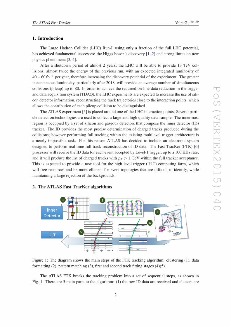
Figure 1: The diagram shows the main steps of the FTK tracking algorithm: clustering (1), dataformatting (2), pattern matching (3), first and second track fitting stages (4)(5).
The ATLAS FTK breaks the tracking problem into a set of sequential steps, as shown inFig. 1. There are 5 main parts to the algorithm: (1) the raw ID data are received and clusters are
2

PoS(VERTEX2015)040
The ATLAS Fast Tracker Volpi G.,14a,14b
found; (2) the clusters are then geometrically organized into overlapping towers and independentlyprocessed, increasing the throughput; (3) within each tower, clusters are matched to predefinedroads; candidate tracks are found using 8 of the 12 available detector layers; (4) a first track fit isperformed only using clusters within the found road, thus greatly reducing the hit combinatorics;(5) all combinations of hits passing the first fitting stage are then further refined by using data inthe layers not included in the previous step.
The key idea is to efficiently perform the pattern matching by prestoring the sequence of hitsrelated to real tracks, using a large dictionary. In order to limit the number of patterns to a realisticnumber, the hits are compared with the prestored tracks at coarse resolution. This pattern matchingscheme is particularly efficient when Associative Memory (AM)[7] chips are used, as successfullyshowed in the CDF experiment[8]. This device is in fact able to perform the matching while thedata are being loaded. In the FTK, a new version of the chip will be used. The new version hasgreater pattern density, allowing about 109 patterns to be stored, and it provides variable resolutionmatching[9], adding the necessary flexibility to work at the challenging conditions of the LHC.
After the pattern matching is performed by the AM system, the hits are organized in roads. Ineach road, all track candidates are tried. The track parameter evaluation has been reduced to a setof scalar products:
pi =∑j
Ci j · x j +qi ∀i = 1 . . .5 (2.1)
χ2 =∑
l
(∑
jAl j · x j + kl
)2
(2.2)
where pi represents the five perigee parameters of a track, and χ2 is the quality parameter. The x j
are the cluster local coordinates; Ci j, Al j, qi and kl are constants used by the linearized formulasand valid in a limited detector region, shared by groups of patterns. The same fitting formulas, withdifferent coefficients and numbers of coordinates, are used in both fitting stages. During both trackfitting stages a missing layer is allowed to maintain overall tracking efficiency.
3. The FTK hardware pipeline
The algorithms showed in Fig. 1 are implemented in specific electronic boards, designed usingVME and ATCA standards. The ATCA shelves will be placed at the entry and at the final point ofthe system. The VME standard will be used for the core boards, which will be responsible for thepattern matching and track fitting.
The final system will have about 8000 AM chips and 2000 FPGAs. This huge computingpower will be distributed in 32 data formatter (DF) boards, 128 associative memory boards (AMB-SLP or AMB) and auxiliary cards (AUX), 32 second stage boards (SSB), and 2 FTK to Level-2interface cards (FLIC). A description of each board type is presented in the following sub-sections.
3.1 Clustering reconstruction and data formatting
This is the entry point of the system and it consists of 32 ATCA boards called Data Formatters(DFs) (Fig. 2). Each DF receives data from the ATLAS inner detector read-out drivers (RODs)
3

PoS(VERTEX2015)040
The ATLAS Fast Tracker Volpi G.,14a,14b
(a) Data formatter board (b) Input mezzanine
Figure 2: The pictures show a fully stuffed DF board (a), with 4 FTK_IM installed. The rightfigure shows a detailed view of the a FTK_IM prototype, with the two FPGAs close to the FMCconnector. A fully loaded DF is able to receive 16 fibers.
through up to 4 daughter cards, the FTK input mezzanine (FTK_IM). Each FTK_IM receives upto 4 fibers, each with a data bandwidth of 2 Gbps. The FTK_IM system will receive in total 380links, in total about 750 Gbps of raw ID data.
The goal of the FTK_IM is to find clusters in incoming data. In case of strip sensors, a partialclustering is already performed at the sensor’s front-end. However for pixel sensors, single channelsare read out and it is necessary to perform a 2D clustering algorithm to find all clusters while dataare loaded at 40 MHz. This step provides a major data reduction at the same time increasing trackreconstruction precision. In order to balance the computational load between the two FPGAs, 2 ofthe 4 input fibers will come from the strips while the other 2 from the pixel sensors. More detailscan be found in [10].
The DF board geometrically organizes the incoming clusters. This board arranges the clustersin η − φ 1 projective towers, with a dimension of δφ × δη ≈ 32◦× 1.2, and in logical layers tobe sent to the core crates. Each DF is expected to provide data to 4 core processors and 1 SSBboard, equivalent to 2 FTK towers, with the possibility to send data to other DF boards in casethe clusters belong to towers not served by the current DF. The connection with the processingunits uses optical links placed in the RTM module. The connection with other DF boards in thesame crate exploits the full-mesh backplane. The DF boards are distributed in multiple ATCAshelves and the inter-shelf communication is provided by an extra link on the RTM. The board hasa communication power exceeding the peak requirements for the next 5 years. To summarize themaximum bandwith through the DF, each board receives up to 32 Gbps from the ID RODs assigned
1φ is the azimuthal angle measured around around the beam axis, while η is linked to the polar angle θ from thebeam axis, defined as η =− ln tan(θ/2).
4

PoS(VERTEX2015)040
The ATLAS Fast Tracker Volpi G.,14a,14b
to a tower, about 30 Gbps of data are sent to the core processors, while up to 40 Gbps of data canbe sent to other DFs in the same shelf and about 25 Gbps to the DFs in other shelves.
3.2 Core processing unit and AM chip
(a) Associative Memory board (b) Auxiliary card
Figure 3: The two pictures show a fully loaded AMBSLP board, with 4 LAMB cards installed,holding a total of 64 AM chips. The AM chips are not installed in the photograph, but the socketfootprint is clearly visible. The right picture shows an AUX card with its 6 Arria V FPGAs, butwithout the heat sinks.
The central part of the FTK pipeline is the system of AM and AUX cards. These two boardsperform the pattern matching and the first stage fit, which are the most computing intense steps ofthe pipeline.
Data are received by the AUX card through QSFP connectors, situated near the bottom andtop of the front panel (Fig. 3b). Data for the tower processed by the unit are received from the DF,already organized by layer. Two main functions are performed within the card: the data organizer(DO) and track fitter (TF). The DO is a smart database organizing all clusters according to a coarseresolution position identifier, the super-strip (SS). The SS is sent to the AM system for patternmatching and it represents the best precision available in the pattern bank. In the TF, the AUXreceives the list of found roads from the AMBSLP. According to the SS content of each road, theclusters are retrieved by the DO; the packet of hits belonging to each road are then sent to the TF.The TF builds all combinations of clusters in a road, with 1 cluster per layer, evaluating the χ2 andsending all good candidate tracks to the next board, the SSB.
The AUX computation is distributed in 6 identical Altera Arria V FPGAs: 4 are devoted tothe DO and TF, while the other 2 handle the input and output as well as the conversion of cluster
5

PoS(VERTEX2015)040
The ATLAS Fast Tracker Volpi G.,14a,14b
locations to super-strips.The AM board, also referred to as AMBSLP[12] contains a large number of serial links. It
receives the SSs from the AUX and sends them to the AM chips. Internally, data are replicated toreach all the chips at the same clock cycle. After the last SS of the slowest layer is received, thelist of fired roads is collected and sent to the AUX for the track fitting. The board is controlled by4 FPGAs: 2 Xilinx Artix 7 which control the input and output logic, 1 FPGA which controls theVME interface, and 1 FPGA controlling the state of the board. The pattern matching function isdone by 64 AM chips installed within 4 LAMB mezzanine cards, clearly visible in Fig. 3a.
Summarizing the data throughput, the AUX receives 6.4 Gbps data from the DF and it has a6.4 Gbps data channel toward the SSB. The connection between the AMB and AUX uses the P3connector, in which high speed serial links provide 12 Gbps from the AUX to the AMBSLP and 16Gbps from the AMBSLP to the AUX.
3.3 Final track fitting and HLT connection
(a) Second stage board prototype (b) FTK to Level-2 interface board prototype
Figure 4: The left picture shows a recent prototype of the SSB. In the center of the board, the 4FPGAs devoted to the final track fit are clearly visible. The right picture shows a FLIC board.
The track candidates coming from the AUX card do not exploit the full precision of the ATLASID because they do not use some of the layers. In the pattern recognition stage, the innermost pixellayer sensor, the insertable B-layer (IBL) detector, and most of the stereo strip layers are not used.These are added in the second stage, as shown in Fig. 1, to improve the quality of the tracks. Themaximum amount of data that are expected into the SSB is 6.4 Gbps/AUX, for a total of 25 Gbps.
The final track refinement is performed by the second stage board, the SSB. This board iscontained in the same VME crate as the AMBSLP and AUX, with 1 SSB connected to 4 AMB-SLP/AUX pairs. Along with the track candidates from the AUX, the SSB also receives data fromthe DF for the layers that are not used in the first stage. The incoming DF clusters are stored in theSSB DO after a SS calculation; the 8-layer combinations coming from the AUX are subsequentlyextrapolated to the additional layers and the hits are retrieved from the SSB DO. If any hits in atleast 3 of the additional 4 layers are found, the track is fit; otherwise the original track is discarded.
6

PoS(VERTEX2015)040
The ATLAS Fast Tracker Volpi G.,14a,14b
The FTK tracking procedure can produce duplicate tracks which are removed by the SSB. Thefinal track candidates are stored in a buffer. Before a new track is included, it is compared with theones already found. If two tracks are considered to be duplicates, based on the number of sharedclusters, one or the other is kept based on the χ2 and the layers used by the TF. Because the FTKtowers have a generous overlap at the boundaries, a large number of duplicated tracks appears inthese areas. In order to perform cross tower duplicate removal, the output tracks are also sent tothe SSB of the next tower before being sent to the final system board, the FLIC board.
The FLIC board’s task is to collect tracks coming from the SSB boards, and convert them intoa format compatible with the HLT software. Particularly, during the various steps showed in Fig. 1,the information is reduced, with the goal of saving bandwidth (for instance, the track parametersare represented as fixed precision integers, in units not compatible with other ATLAS algorithms).The FLIC board has all the information required to convert the tracks to the format needed by theHLT algorithms. The FLIC system has a total input and output bandwidth of 32 Gbps.
4. Expected results and use in HLT
(a) FTK tracking efficiency (b) B-tagging
Figure 5: The plots in the figure are obtained using the FTK emulation [6]. The plot on the leftshows the efficiency of the FTK tracking algorithm, with respect to the tracks found by offlinetracking algorithms, as a function of pT for muons and pions. The right plot shows a comparisonof b-jet tagging algorithm performance between the case when precise tracking information fromoffline algorithms is used (black) and when tracks found by the FTK hardware are used for threechoices of light flavor rejection in the FTK-based algorithm.
The FTK performance has been simulated in detail to tune the algorithm parameters and studythe improvements to the HLT selections. FTK tracks are generally found to have a resolutioncomparable to the offline algorithms. Relative tracking efficiency is about 95% and the fake rate isof about 5% at pileup of 70 interactions per beam crossing[6].
Because the FTK tracks are present at the beginning of the HLT, event processing can im-plement complex algorithms based on tracks, not currently available, which can reject difficultbackgrounds. This is expected to be beneficial for the identification of τ hadronic decays as well asb-jet and exclusive b-hadron decays. Where required, the FTK track quality can even be improvedby refitting the FTK tracks using the HLT algorithms. Two summary plots are shown in Fig. 5.
7

PoS(VERTEX2015)040
The ATLAS Fast Tracker Volpi G.,14a,14b
Milestone IM DF AUX AMB Chip SSB FLIC ETAFull Slice Test (AMChip05) 4-16 1-4 1 1 x05 1 2 09/15Full Slice Test (AMChip06) 128 32 16 1 x06 8 2 11/15Full barrel coverage (µ = 40) 128 32 16 16 x06 8 2 02/16Full coverage (µ = 40) 128 32 32 32 x06 16 2 08/16Full System 128 32 128 128 x06 32 2 2018 -
Lumi-nositydriven
Table 1: The table shows the expected status of the board and the system at the different milestones.A first complete chain is expected to be operational by the end of 2015, with the AMB based onthe AMChip05. When a large number of the AMChip06 will be available, the system will continueto grow, reaching full coverage by summer 2016.
The FTK tracks can also be used to mitigate the effects of pileup in missing energy selectionsby combining calorimetric and tracking information. The availability of tracks for all the eventsthat enter the HLT will also allow other generic uses, such as the reconstruction of all primaryvertices in the events.
5. Commissioning schedule
The FTK system is in a very advanced development stage. The production of some boards hasalready started, while in the other cases it is ready to start. The key component is the AMChip06,already submitted for initial production, and the first few thousand chips are expected to be receivedin October.
The FTK commissioning schedule in Table 1 expects a first full slice of the system, with atleast one board of each kind by the end of 2015. A fully working system, which will be able toreconstruct tracks in the whole barrel region, is expected early in 2016, with full inner detectorcoverage by the summer.
The commissioning of the complete system (128 AM boards) will be staged based on theexpected LHC luminosity and will be complete by 2018.
6. Conclusions
The ATLAS FTK processor will be able to provide high quality tracks to all the HLT algo-rithms at the full Level-1 rate. This offers new possibilities to the HLT to collect large samples ofinteresting physics channels, usually difficult to collect because of large backgrounds. The collec-tion of events with τ leptons or b-jets will be more efficient by allowing the tracker information toidentify their very unique topologies. FTK track reconstruction will also provide reduced sensitiv-ity to pileup by its precise reconstruction of the collision vertices and its ability to identify objectsoriginated from different collisions.
8

PoS(VERTEX2015)040
The ATLAS Fast Tracker Volpi G.,14a,14b
The hardware is ready for production and a first complete slice will be tested during this year’sdata taking. There will be sufficient hardware to cover the barrel region, with |η | ≤ 1, by spring of2016, and full η coverage by the end of 2016.
Acknowledgements
The Fast Tracker project receives support from Istituto Nazionale di Fisica Nucleare; the USNational Science Foundation and Department of Energy; Grant-in-Aid for Scientific Research fromthe Japan Society for the Promotion of Science and MEXT, Japan; the Bundesministerium fuÌLrBildung und Forschung, FRG; the Swiss National Science Foundation; the European communityFP7 People grants ARTLHCFE 254410 FP7-PEOPLE-2009-IOF and FTK 324318 FP7-PEOPLE-2012-IAPP; the Agence Nationale de la Recherche, project "FastTrack" n. ANR-13-BS05-0011,France; and GSRT, NSRF and IKY, Greece.
References
[1] ATLAS Collaboration, “Observation of a new particle in the search for the Standard Model Higgsboson with the ATLAS detector at the LHC,” Phys. Lett. B 716 (2012) 1 [arXiv:1207.7214 [hep-ex]].
[2] CMS Collaboration, “Observation of a new boson at a mass of 125 GeV with the CMS experiment atthe LHC,” Phys. Lett. B 716 (2012) 30 [arXiv:1207.7235 [hep-ex]].
[3] ATLAS Collaboration, “Summary of the searches for squarks and gluinos using√
s = 8 TeV ppcollisions with the ATLAS experiment at the LHC,” arXiv:1507.05525 [hep-ex].
[4] ATLAS Collaboration, “ATLAS Run 1 searches for direct pair production of third-generation squarksat the Large Hadron Collider,” arXiv:1506.08616 [hep-ex].
[5] ATLAS Collaboration, “The ATLAS Experiment at the CERN Large Hadron Collider,” JINST 3(2008) S08003.
[6] ATLAS Collaboration, “Fast TracKer (FTK) Technical Design Report”, CERN-LHCC-2013-007,ATLAS-TDR-021
[7] F. Morsani et al., “The AMchip: A VLSI associative memory for track finding”, Nucl. Instrum. Meth.A315, 446 (1992)
[8] S. Belforte et al., “The CDF trigger silicon vertex tracker (SVT)”, IEEE Trans.Nucl.Sci. 42, 860(1995)
[9] A. Annovi et al., “A new variable-resolution associative memory for high energy physics”, (Int. Conf.on Advancements in Nuclear Instrumentation Measurement Methods and their Applications,ANIMMA), Proc. IEEE 116, 117 (2011).
[10] C. L. Sotiropoulou et al., “A Multi-Core FPGA-Based 2D-Clustering Implementation for Real-TimeImage Processing,” IEEE Trans. Nucl. Sci. 61 (2014) 6, 3599.
[11] P. Luciano et al., “The Serial Link Processor for the Fast TracKer (FTK) processor at ATLAS,” PoSTIPP 2014, 210 (2014).
[12] Alberti F. et al, “Performance of the AMBFTK board for the FastTracker Processor”, JINST 8 (2013)C01040
9