the peace river bridge collapse - cruden peace river changes... · the peace river bridge collapse...
TRANSCRIPT
The Peace River Bridge Collapse:
Fourteen Illustrations of the Collapse of the Bridge over the Peace River at Taylor, British Columbia in October, 1957 with some personal recollections
by
S. Thomson
with a Preface by
D. Cruden
both Emeritus Professors at the Department of Civil Engineering
University of Alberta
Edmonton, Canada T6G 2W2
for the Heritage Committee
Canadian Geotechnical Society, 2010

Preface
As the Canadian member of the International Association for Engineering Geology’s Commission on Landslides, I was asked to organize the Canadian Contribution to a Symposium on the Extent and Economic Significance of Landslides at the 28th International Geological Congress in Washington, D.C. in July 1989 (Brabb and Harrod, 1989). I persuaded Stan Thomson, who had then recently retired from the Department of Civil & Environmental Engineering at the University of Alberta to describe landslides on the Interior Plains.
Stanley Thomson graduated from the University of Toronto in 1950 after serving with the RCAF during World War II. Recruited by the Royal Canadian Engineers, he was posted to Whitehorse in 1954 as Soils Engineer for the Alaska Highway in Canada. He commanded ferry operations for the detour necessitated by the collapse of the Peace River Bridge. Stan joined the staff of the University of Alberta in 1959 and was awarded the University’s first doctorate in soil mechanics in 1963.
The Peace River Bridge collapse was a case history in the 15 page manuscript Stan contributed to the paper by Cruden et al., (1989) in the IGC Symposium. Unfortunately, three figures and a considerable amount of the original text fell victim to space restrictions in the published volume. The following account of the actual bridge collapse is Stan’s commentary on an additional sequence of 10 contemporary undocumented photographs made available to us recently.
Introduction
The impressive bridge that spanned the Peace River south of Fort St. John, British Columbia, was erected in less than nine months from November 1942 by the Dufferin Paving Company (Toronto, Ontario) and John A. Roebling’s Sons Company (Trenton, New Jersey, U.S.A) under contracts from the Fort St. John Division, Alaska Highway District, Public Roads Administration, U.S. Federal Works Agency(Carrigan, 1943) .
In October 1957, the north abutment of the Peace River Bridge (Fig. 1) was caught in a landslide which culminated in the collapse of the approach span and a side span (Thomson, 1958). The suspension bridge consisted of two approach spans, each 38.1m (125 feet), 2 side spans of 141.7m (465 feet) and a main centre span of 283.5m (930 feet) for a total span of 640m (2100 feet). The loss of this bridge resulted in a complete disruption of all traffic to communities along the Alaska Highway as far north as Whitehorse, Yukon, 1475km away.
On the north side of the Peace River, a terrace, 45m above river level, was capped by 12m of clean, sandy gravel. The terrace was eroded into clay shale of the Upper Cretaceous Shaftesbury Formation. A road cut through the gravel into the clay shale had been made to the level of the bridge deck. The general area prior to the failure is shown in Fig. 2. A massive gravity abutment, founded on clay shale, acted as the anchor for the suspension cables. The road cut allowed ingress of water to the clay shale, which, in 15
years, weathered to a highly plastic clay. The loss of strength of the clay shale since construction of the bridge was the major cause of the landslide that led to the loss of the bridge. The collapsed spans and part of the scarp are shown in Figs. 3 and 4.
The Bridge Collapse
A general view from the north-east on the morning of 16 October (Fig. 5) shows the centre span, perhaps sagging. The upstream faces of the piers slope westwards and are semi-circular in plan. Debris coming down the river seemed to ride up the piers and fall off.
In Figure 6, the anchor block and north abutment have moved riverward and downward. The roadway on the abutment appears to have moved under the truss (Figure 7, 8) distorting the truss where it joins the abutment. The truss has been forced riverwards as the abutment has moved – note the gap behind (and north) of the abutment. The abutment was about 9 metres (30 feet) wide, about the distance the abutment moved. The truss moved the same distance without significant distortion but has distorted the cable bent.
People on both sides of the abutment are close to the crown of the slide. The scarp can be seen in Figure 6 along with ground that emerges from the river.
In Figure 7, the gap behind the anchor block appears to be about the same width as in Figure 6. Hence Figure 7 appears to be taken soon after Figure 6. The distortion of the cable bent at the top of the north pier is clear. The entire cable bent is leaning towards the river.
Faint shadows near the edge of the river may be evidence of the toe of the landslide. Not visible on this photo (but seen in Figure 4, taken after the event) are the pipelines delivering water to the gas cleaning plant located on the high level terrace just above the slide. Apparently, the pipelines have not broken completely but are likely leaking strongly and causing some slope erosion independent of landslide movement.
The abutment has a small tilt riverward. The truss is distressed only at its ends; it has not buckled but is forcing the cable bent out-of-position and, eventually, off its foundation.
Figure 8 shows more riverward movement and greater tilt of the anchor block. The three figures are in somewhat precarious locations.
In Figure 9, the bridge deck seems to be over-riding the abutment which is tilting more and going under the road. The road bed appears kinked at the junction between the truss and the suspended side span. This probably shows more movement in the cable bent. There is a down-river tilt to the anchor block, likely the effect of pipelines breaking and water gushing out causing more slope erosion.
Figure 10 shows the cable bent pushed right off its foundation. The cables form straight lines from the anchor to the North tower. The lines placed a great deal of strain on the hangers, visible in Figure 5. The hangers broke and the side span collapsed. The truss had collapsed earlier when the cable bent was pushed from its foundation. Note the way the cable bent is falling. The distorted part is the top of the bent. Figure 7 suggests the bent is being pushed over at its top; it should topple towards the river and Figure 10 should show the base, not the top. If the bent were pushed off but held temporarily by the connectors where the cables went over the bent (visible on the cables in Figures 10, 11, 12) for sufficiently long to let the base of the bent move downhill – before the connecting saddles broke, the result would be as seen in Figures 10, 11, 12.
In Figure 11 and 12 the dust of the collapse covers any features of interest. Pipelines have broken and have spilled water down the slope to the northeast of the bridge, eroding much of the base of the slope. The full damage is unknown.
Figures 13 and 14 show the centre span sagging. The collapse caused the cables from the North Tower supporting the side span to straighten. Compare the cables the side span in Figure 5 with those in Figures 13 and 14. The positions of the cables above the north side span probably changed very rapidly as the cable bent was pushed off its foundation.
The Aftermath
The complete disruption of traffic lasted for seven days until a 70 ton ferry was installed and approach roads constructed. It operated 24 hours a day until 0800 hours on 18 November 1957. The weather was rainy with freezing periods hence the gravel road required constant grading and, in addition, the river level rose several times requiring reconstruction of the ferry slip.
The Pacific Great Eastern Railway allowed their rail bridge to be used for a detour route across the river during the two years until the Peace River Bridge could be replaced. It was 5km upstream from the collapsed bridge site. A narrow dirt road nearly to the railway bridge site on either side of the river required relocation, widening, and gravelling of the road surface. The railway bridge had railway track laid but had to be decked and curbed and a guardrail added for road vehicles. Since it was single lane, traffic control had to be supplied at each end of the bridge. In addition, the detour route had to cross the tributary Pine River. The first bridge across this tributary was a simple timber structure that was severely damaged by a sudden increase of the river flow. A subsequent Bailey bridge served throughout the remainder of the life of the detour.
The direct costs (Fleming and Taylor, 1980) included :
(a) dismantling the collapsed structure, a winter operation with ice on the river used as a working platform,
(b) design and construction of a new bridge, an over-deck truss 30m longer than the original span, at 670m.

These costs are estimated to be 110 million (2010) dollars.
The indirect costs included :
(a) construction and operation of the ferry crossing from 21 October to 18 November 1957 on a 24-hour per day basis,
(b) construction, maintenance and operation of the detour route, 10km of gravel road, the crossing of the Pine River, the decking of the Peace River railway bridge, sign posting and traffic control for two years,
(c) the cost in time and fuel to vehicular traffic of an extra 10km,
(d) the cost to vehicles and travelers on the Alaska Highway, north of the collapsed bridge of being stranded for 5 to 7 days,
(e) the cost to all businesses north of the bridge of loss of trade by lack of supplies as well as stores, service stations, and motels there was much gas and oil exploration near Fort Nelson, 400km further north,
(f) the cost of the shut-down of the natural gas cleansing plant (immediately north of the bridge) which lost its water supply in the slide.
An estimate is 36 million dollars (2010).
There was a strong economic impact. At $146 million, the landslide that caused collapse of the Peace River Bridge may have been the costliest in Canada. There was no loss of life or private property and no consequent legal activity.
Acknowledgements
We are grateful to Brendan Miller for drawing these photographs of the bridge collapse to our attention and for useful discussions. Our thanks to Dave Baker who provided scans of the photographs given to his wife’s grandmother, Iris Hunter, by George Simpson, an employee at the natural gas processing plant at the time of the collapse.

References
Brabb, E.E., Harrod, B.L., editors, 1989, Landslides: Extent and Economic Significance, Balkema, Rotterdam, 385p.
Carrigan, C.J., 1943, Final Constuction Report on Peace River Bridge , Structure 102, Fort St.John Division, Alaska Highway District, U.S. Public Roads Administration, 23p.
Cruden, D.M., Bornhold, B.D., Chagnon, J-Y., Evans, S.G., Higinbottom, J.A., Locat, J., Moran, K., Piper, D.J.W., Powell, R., Prior, D., Quigley, R.M., Thomson, S., 1989, Landslides: Extent and Economic Impact Significance in Canada, in Brabb, E. Editor, Landslides: Extent and economic significance. Balkema, Rotterdam pp 1-24
Fleming, R.W., Taylor, F.A., 1980, Estimating the costs of landslide damage in the United States, United States Geological Survey Circular 832, 21 p.
Thomson, S., 1958, Collapse of the Peace River Bridge, The British Columbia Professional Engineer, May, pp 13-15
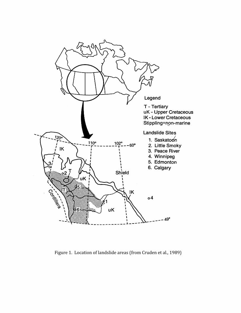
Figure 1. Location of landslide areas (from Cruden et al., 1989)

Figure 2. Peace River Bridge, 1956. The Peace River flows from left (west) to right. The Pine River enters the Peace River in the lower left of the photo.
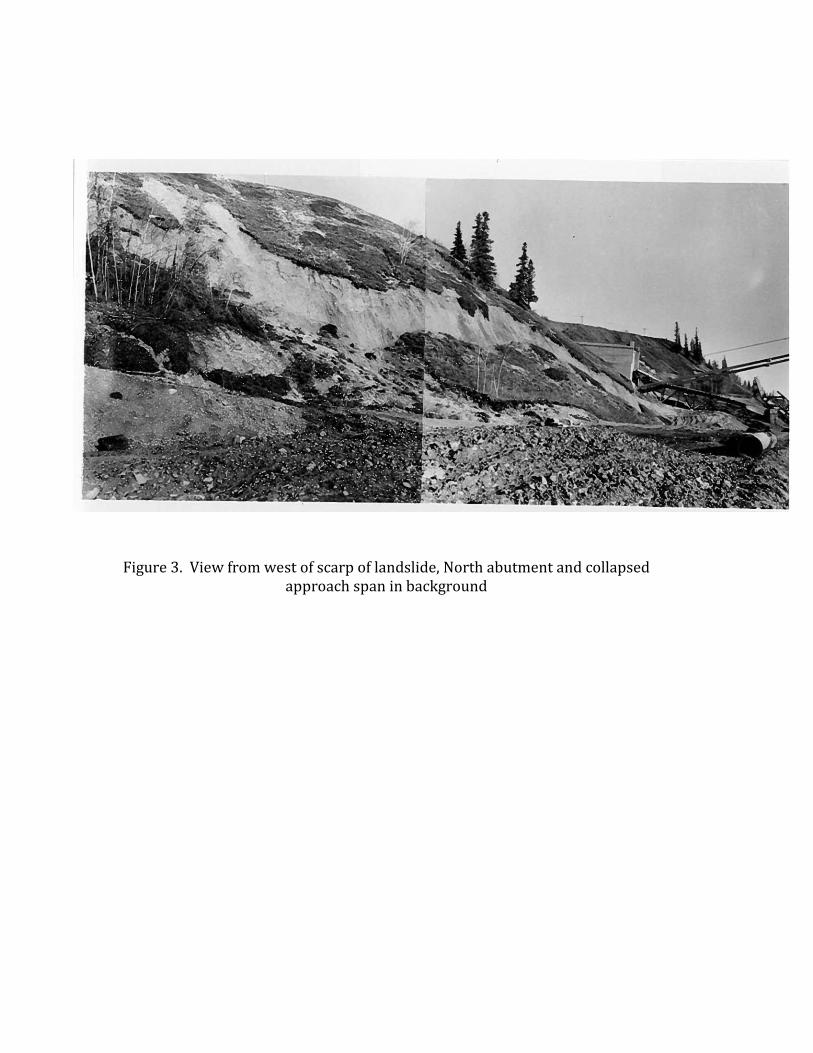
Figure 3. View from west of scarp of landslide, North abutment and collapsed approach span in background
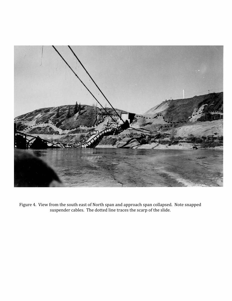
Figure 4. View from the south east of North span and approach span collapsed. Note snapped suspender cables. The dotted line traces the scarp of the slide.
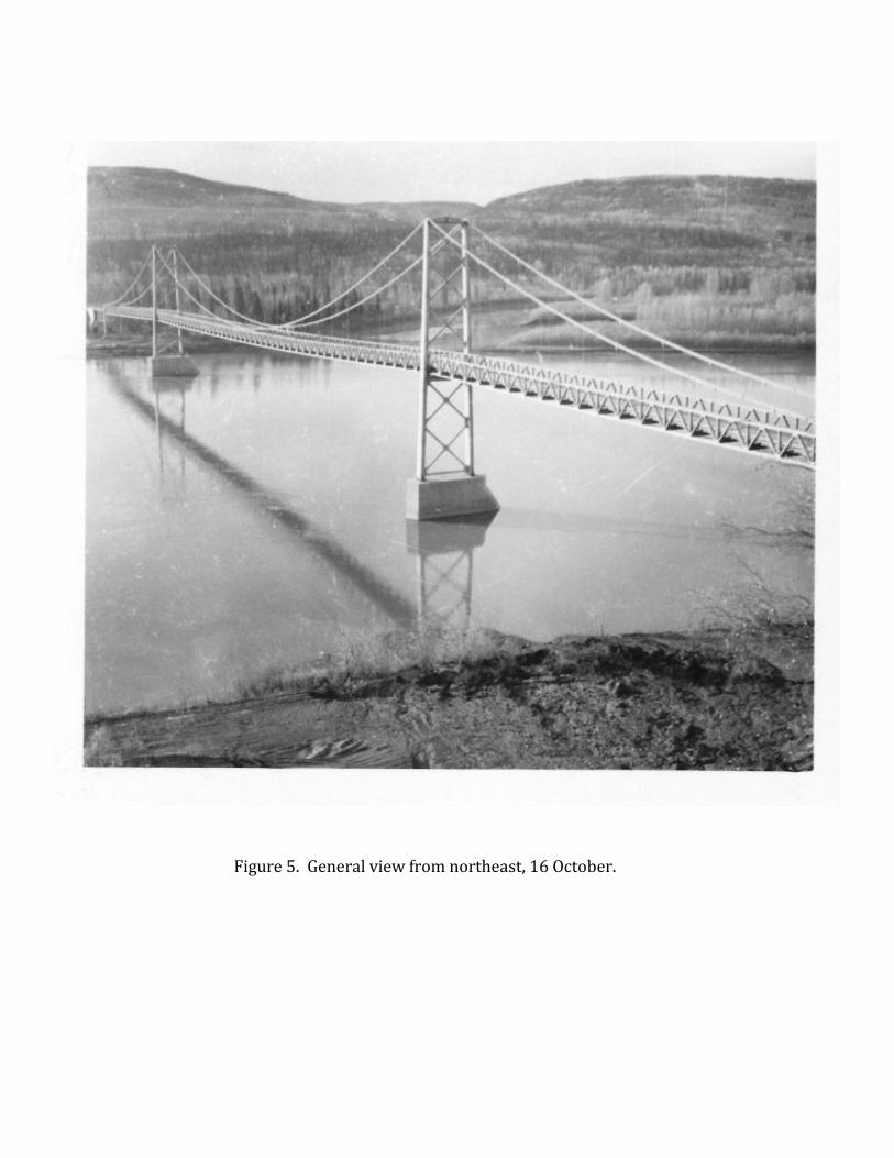
Figure 5. General view from northeast, 16 October.

Figure 6. Anchor block and north abutment. Persons give scale.
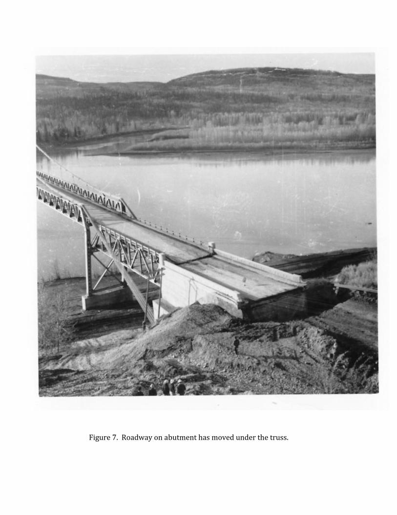
Figure 7. Roadway on abutment has moved under the truss.
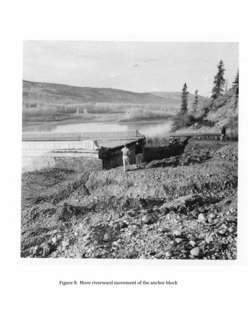
Figure 8. More riverward movement of the anchor block
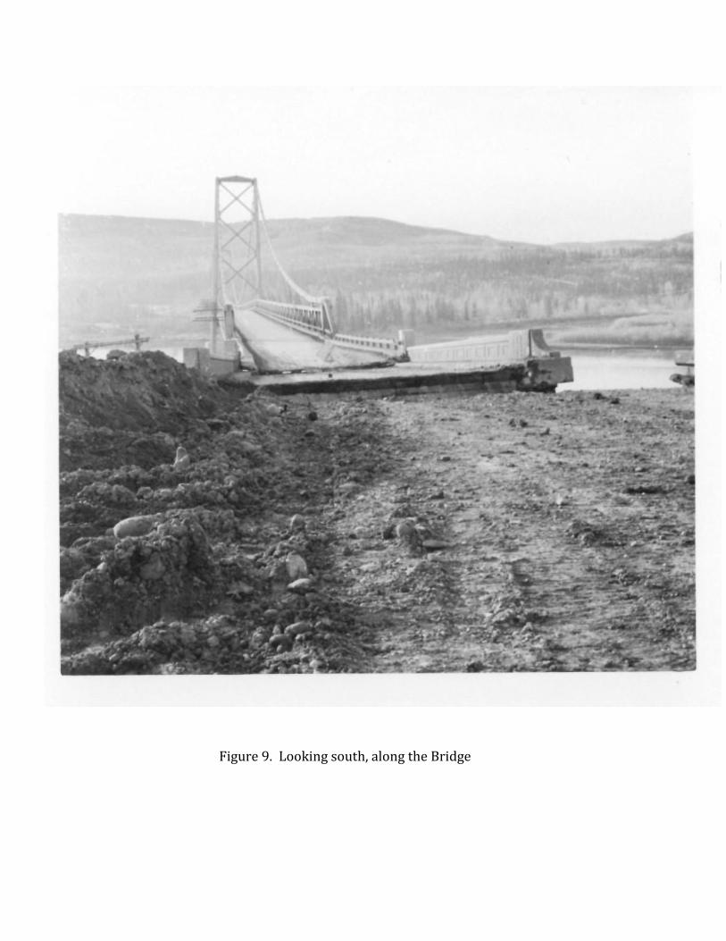
Figure 9. Looking south, along the Bridge
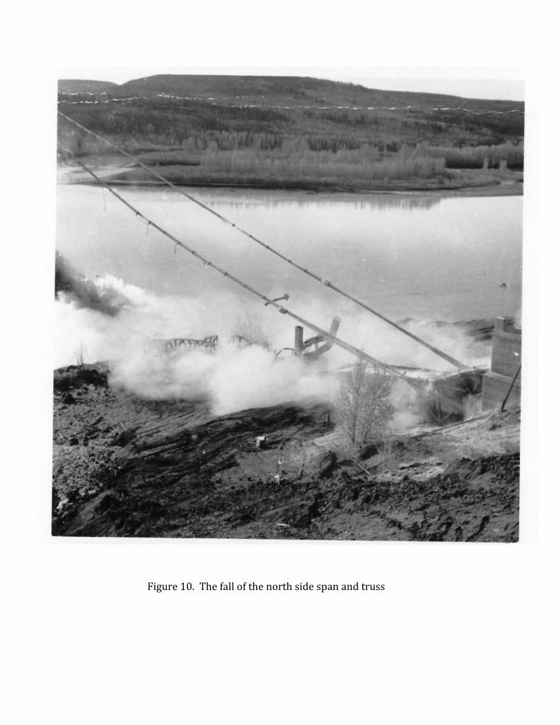
Figure 10. The fall of the north side span and truss
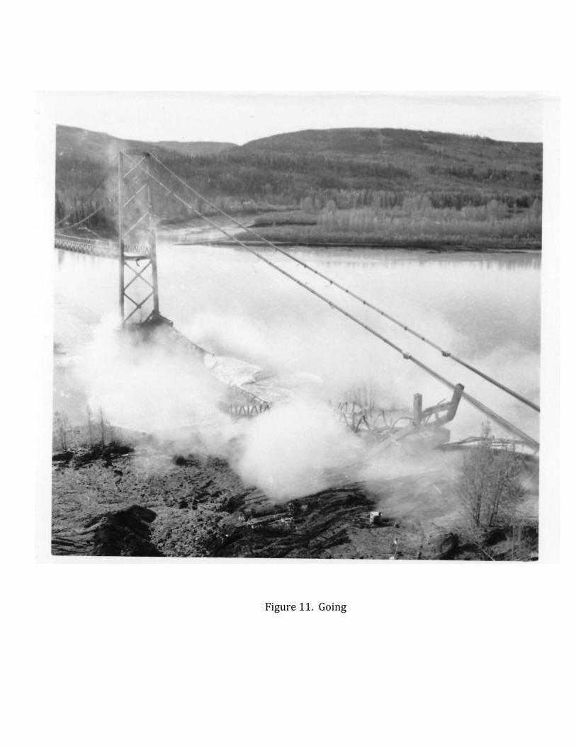
Figure 11. Going
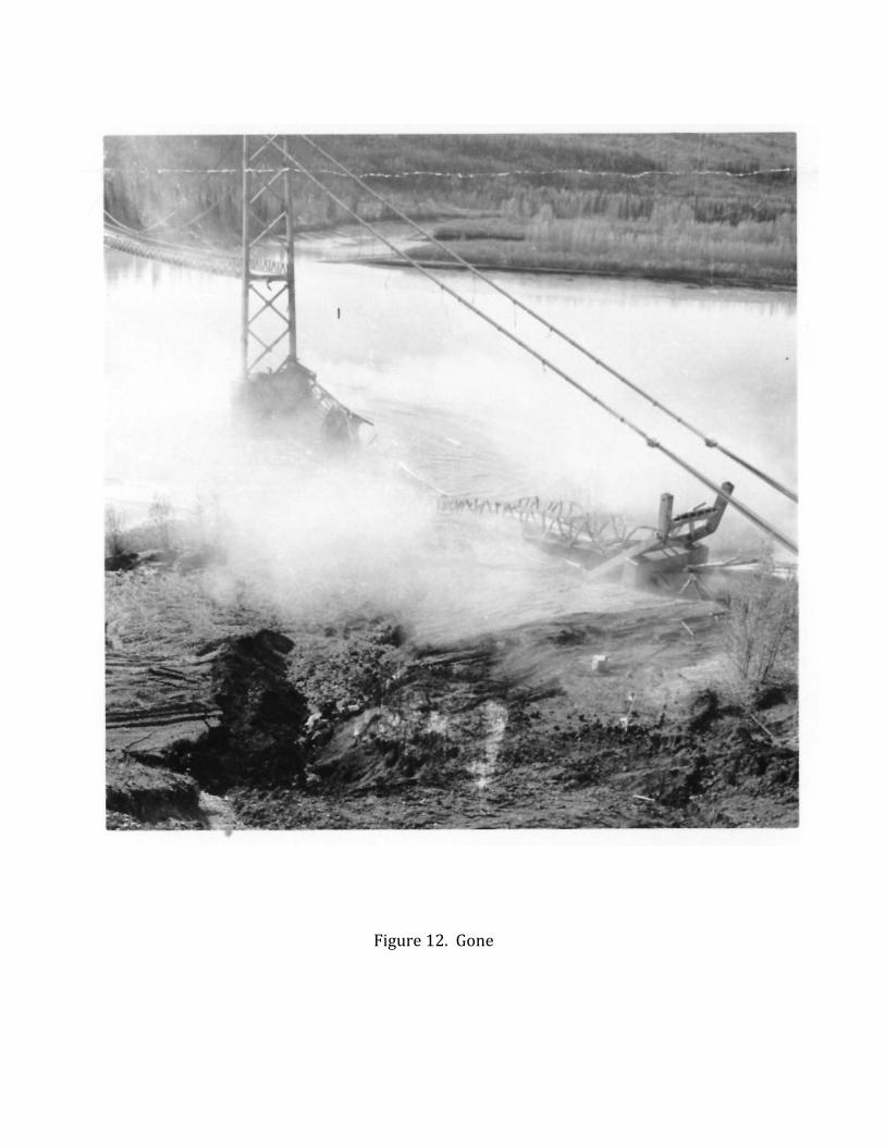
Figure 12. Gone
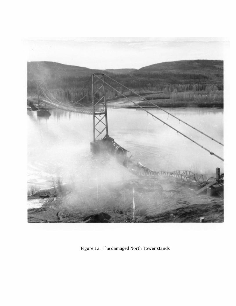
Figure 13. The damaged North Tower stands

Figure 14. As the dust settles