thermoelectric generator placed on the human body: system
TRANSCRIPT
HAL Id: hal-00624423https://hal.archives-ouvertes.fr/hal-00624423
Submitted on 17 Sep 2011
HAL is a multi-disciplinary open accessarchive for the deposit and dissemination of sci-entific research documents, whether they are pub-lished or not. The documents may come fromteaching and research institutions in France orabroad, or from public or private research centers.
L’archive ouverte pluridisciplinaire HAL, estdestinée au dépôt et à la diffusion de documentsscientifiques de niveau recherche, publiés ou non,émanant des établissements d’enseignement et derecherche français ou étrangers, des laboratoirespublics ou privés.
Thermoelectric generator placed on the human body:system modeling and energy conversion improvements
M. Lossec, Bernard Multon, Hamid Ben Ahmed, C. Goupil
To cite this version:M. Lossec, Bernard Multon, Hamid Ben Ahmed, C. Goupil. Thermoelectric generator placed on thehuman body: system modeling and energy conversion improvements. European Physical Journal:Applied Physics, EDP Sciences, 2010, 52 (1), pp.11103. 10.1051/epjap/2010121. hal-00624423

1
Thermoelectric generator placed on the human body: system modeling and energy conversion improvements
M. Lossec(1), B. Multon(1), H. Ben Ahmed(1), C. Goupil(2) (1)SATIE, ENS CACHAN Brittany Campus, CNRS, UEB
Avenue Robert Schuman, F-35170 BRUZ www.satie.ens-cachan.fr
(2)CRISMAT-CNRT ENSICAEN 6 Boulevard Maréchal Juin, F-14050 CAEN
Phone: +33 (0)2 99 05 93 22, e-mail: [email protected] Abstract This paper focuses on the production of electricity using a thermoelectric generator placed on the human body connected to a DC-DC converter. The small difference in temperature between the hot heat source (e.g. the human body, Tb = 37°C) and the cold heat source (e.g. ambient air, Ta = 22°C), associated with a poor quality thermal coupling (mainly with the cold source), leads to a very low temperature gradient at the thermoelectric generator terminals and hence low productivity. Under these use conditions, the present article proposes an analysis of various ways to improve productivity given a surface capture system. Furthermore, we demonstrated, in this particular context, that maximizing the recovered electric power proves to be a different problem from that of maximizing efficiency, e.g. the figure of merit Z. We therefore define a new factor ZE, depending on the physical characteristics of thermoelectric materials, that maximizes electric power in the particular case where the thermal coupling is poor. Finally, this study highlights the benefit of sub-optimization of the power extracted from the thermoelectric generator to further improve efficiency of the overall system. We show that, given the conversion efficiency of the DC-DC converter, the maximum power point of the overall system is no more reached when the output voltage of the thermoelectric generator is equal to half of its electromotive force. Keywords: Thermoelectric generator, thermoelectric modeling, productivity improvement, electric power maximization, system energetic approach. 1. Introduction The increasing needs associated with portable electronic devices (medical applications, entertainment, communications, etc.), which are often communications-driven, have raised additional difficulties in terms of energy self-sufficiency. Lowering the consumption of electronic functions makes it possible to envisage self-sufficiency from local supply resources. Since the end of the 1990's, a new problem situation has thus appeared: supplying portable electronic devices with energy recovered in the human environment [1,2]. Thermogeneration [3] represents one possible solution; it involves placing one side of the thermoelectric module into contact with the skin of the human body and the other in direct contact with ambient air (see Fig. 1). The temperature difference between the two sides is then used to directly convert heat into electricity. Some medical devices, like a pulse oximeter [4] or an electrocardiography system [5], have already been powered by a thermoelectric generator using heat from the skin.
2
The originality of this paper is due to the fact that we think with a system energetic approach, e.g. taking into account the strong coupling of the thermoelectric generator (TEG) with its environment, and also with the DC-DC converter connected to its output. Thus, we do not, as in the thermoelectric theory, consider a temperature gradient at the TEG terminals or a heat flow through it as constant. We are however in the case where two heat sources (the human body and the atmosphere) are set and undisturbed by the presence of the TEG. 2. Thermoelectric modeling steps
2.1. The thermoelectric model In considering the various power sources involved in a module (e.g. heat loss by both the Joule effect and the Peltier effect), as well as the conduction, convection and radiation phenomena acting at the cold and warm module surfaces, we are able to create a thermal model in generator convention, as depicted in Figure 2 [6]. According to this model, the human body and the environment are considered as infinite sources of temperature and unaffected by the TEG. Couplings of the warm and cold sides with temperatures Tb and Ta are respectively represented by thermal resistances
BthR (thermal conduction through the skin between blood circulation and the warm side
of the module) and AthR (radiation and natural convection of the cold side with ambient
air). The thermal resistance GthR describes heat conduction through all Nth
thermocouples, which are thermally connected in parallel and constitute the module. As a final consideration, the approximation that Joule losses are equally distributed on each side is valid since the excess heat is diffused isotropically, especially given that the temperatures of both heat sources are nearly equal.
From a purely electrical standpoint, let's consider the diagram in Figure 3. The TEG behaves like an electromotive force EG proportional to the difference in temperature between warm and cold sides, with α being the Seebeck coefficient of all Nth thermocouples, which are electrically connected in series. RG is the internal resistance and equals to the electrical resistance of the Nth thermocouples connected in series. An adaptive electronic converter (see Fig. 4) allows the generator to operate, regardless of thermal conditions, at maximum power by inputting an equivalent resistance RL equal to RG. If the load is a source of constant voltage (e.g. an accumulator), then the output voltage will be equal to half the emf. Under these ideal adaptation conditions, the maximum deliverable power by the TEG can thus be expressed as follows:
( )=
2
GeM
G
α∆TP
4R (1)
Let ηconv be the energy efficiency of an adaptive converter, then the maximum useful recoverable power PuM is equal to:
=uM conv eMP η P (2)
Note that converter efficiency depends on input and output voltage as well as on output current.

3
2.2. Measurements and calculations of thermoelectric model parameters As indicated in [3,6,7] and as will be briefly recalled in Section 4.1, the efficiency of the module, e.g. the ratio of electric power to heat extracted from the hot source, is optimal when the dimensionless figure of merit ZT = α0
2T /(4ρλ2) is maximized, with α0, λ and ρ being respectively the Seebeck coefficient, and the thermal conductivity and electrical resistivity of the material, and T being the average temperature such that T = (Th+Tc)/2. This condition is only true on an adapted electrical charge, e.g. when the
ratio of load resistance RL to internal TEG resistance RG is equal to 1 ZT + . It will be shown later however that under the conditions of this application, maximizing efficiency does not necessarily yield the maximum recovered electric power. Yet this application seeks to maximize power, given that the amount of thermal power extracted remains very low and is not disruptive. The body is actually being regarded here as an infinite heat source with respect to the amount of extracted power. Since temperatures in our application lie in the vicinity of 300K, the material on the market reputed to offer the best figure of merit within this temperature range is bismuth telluride, e.g.
2 3i eB T . In
what follows, all experiments presented were performed using TM-450-0.8-3.0 modules, produced by the Ferrotec company, based on this alloy; the corresponding specifications are listed in Table 1. A measurement of the load line slope has been used to evaluate the internal resistance of this module, e.g. RG = 14 Ω. 2.2.1. Measurement of the Seebeck coefficient: For this experiment, we implemented a differential measurement with two type K thermocouples from the same batch and connected in series; their external connections were made to be isothermal in order to accurately record the low temperature difference ∆TG between the hot and cold sides of the module. The thermoelectric module was placed on a small aluminum plate (see Fig. 5), which itself was positioned on a hotplate. The aluminum plate was able to accommodate the thermocouple in a thin slot and maintain it in contact with the hot side. On the cold side, a fan served to even the temperature over the entire surface.
The Seebeck coefficient for a module is determined simply by measuring both the emf of the thermoelectric module EG and the difference ∆TG in temperature, as obtained by recording the voltage at the two thermocouple terminals placed on the hot and cold sides. Coefficient linearity could also be confirmed (see Fig. 6) when varying the hot side temperature.
2.2.2. Measurement of thermal resistance: To measure the thermal resistance of a module, the assembly illustrated in Figure 7 has been set up.
A power resistor R, supplied by an electrical generator, creates a heat flow through the module, which in turn generates a temperature gradient. In order to properly even the temperature on both sides of the module, two aluminum plates covered with thermal grease were introduced. A polystyrene insulation serves both to direct this heat flow in

4
the module and to minimize leakage. We would therefore expect that the power through the module is basically equal to that dissipated in the power resistor R. Temperature is measured as before with a differential recording using K type thermocouples. For the module studied, these measurements yielded a thermal resistance
G
1thR 1.1KW−= .
2.2.3. Validation of assumptions allowing for simplification of the thermal model: Let's start by considering the worst case scenario, where the heat flows, and hence losses, are maximized during TEG operations under conditions of small temperature differences for the given application. It is therefore assumed that the thermal contacts of both the hot and cold sides with external sources are ideal. The thermal diagram for this case is shown in Figure 8.
Under these conditions, the heat flow from the hot source is expressed as:
= + −
= + −G
jh ph λ
20 Gh
th
QQ Q Q
2∆T R
T αI IR 2
(3)
Next, in assuming that maximum power can be recovered, the current equals I = α∆T0/(2RG), which then results in the following:
= − +
G
20 0 0
h hG th
α ∆T ∆T ∆TQ T
2R 4 R (4)
Let's now analyze the order of magnitude of Th with respect to ∆T0/4:
0
h b
c a
h c
T T 310K
T T 283 to 303K
T T2 to
4
∆T7K
4
= =
= ≅ − = ≅
Under the special conditions where Th » ∆T0/4 can always be verified, Joule losses are negligible when compared to the power flow due to the Peltier effect. It can be deduced that:
≅ +
G
2b
h 0G th
α T 1Q ∆T
2R R (5)
By assuming that the module is composed of Nth thermocouples thermally in parallel and electrically in series and knowing that a thermocouple is composed of two cells (of the N and P types), it deductively follows that:
=
=
=
Gthth cell
G thcell
th 0
1 1 lR
N λ 2S
2lR N ρ
S
α N α
(6)
where l and Scell are the length and area of a single thermoelement, respectively, as shown in Figure 9.

5
By setting k as a filling factor (less than 1) for cells in the module, we obtain Scell = kSth/(2Nth), where Sth is the total heat exchange surface area of the hot and cold sides of the module. This step allows deriving that:
=
=
Gthth
2G th
th
lR
λkS
4lR N ρ
kS
(7)
Given the approximations adopted, the heat flux Qh is thus expressed as:
≅ +
2th 0
h 0 b
kS αQ ∆T T λ
l 8ρ (8)
The next analytical step focuses on the order of magnitude of the term α02Tb/(8ρ) with
respect to λ (in considering the bismuth telluride material): 1 1
10
21 10
b
λ 0.77W.m .K
α 260µV.K
ρ 20µΩm
αT 0.14W.m .K
8ρ
− −
−
− −
≅ = = ≅
Under these conditions (body temperature and a high-performance thermoelectric material), it is observed that: α0
2Tb/(8ρ) « λ. This observation then simplifies the expression of heat flows Qh ≅ ∆T0/
GthR ≅ Qλ;
similarly, Qc ≅ ∆T0/GthR ≅ Qλ.
The Joule losses and heat flow due to the Peltier effect can therefore be considered negligible compared to the main heat flow. Under the particular conditions of this application, in which the electric power generated remains relatively low, it is possible to simplify the thermal model according to the diagram in Figure 10.
The following expression can then be derived:
=+ +
G
B A G
thG 0
th th th
R∆T ∆T
R R R (9)
2.2.4. Estimated heat transfer coefficients of the module environment: The hot and cold sides of the TEG are connected respectively to the temperature source inside the human body (at about 37°C) through the skin, and to the ambient temperature source (variable depending on external conditions) through convection and radiation effects, with such effects being potentially responsive to external actions.
Conduction resistance between the module and the internal body: With respect to the hot side of the module, the thermal resistance
BthR models the
conduction phenomenon through the skin of the person wearing the module. According to [8,9], a typical heat transfer coefficient between human skin and the module is estimated at: hB ≅ 20 to 100 W.m-2.K-1.

6
This figure results, for the experimental module, in a thermal contact resistance for the hot side of:
BthR = 1/(hBSth) ≅ 3 to 17 K.W-1.
Convection and radiation resistance between the module and ambient air: As for the cold side of the module, thermal resistance
AthR models the phenomena of
natural convection and radiation, both of which are highly non-linear. By means of linearization, we are able to obtain an overall heat transfer coefficient per unit area that depends on ambient and surface temperatures as well as on emissivity. In the absence of movement, the heat transfer coefficient hconv in natural convection can be expressed by the approximated formula [10]:
( )≅ − 0.25
conv c ah 3 T T (10)
Linearizing Stephan Bolzmann's expression for radiated power now provides:
( ) ≅ − ≅ −
≅ + + +
4 4rad th c a rad th c a
3 2 2 3rad c c a c a a
P σεS T T h S (T T )
h σε(T T T T T T ) (11)
σ ≅ 5.7 10-8 SI unit is the Stephan Bolzmann constant and ε ≤ 1 is the emissivity of the surface due to its color and surface condition (a dark and matte surface leads to an emissivity of close to 1, while a shiny surface yields a value of ε tending to 0). Under our experimental conditions (temperatures at approx. 300K), we can determine:
hconv ≅ 6 W.m-2.K-1
hrad ≅ 0 to 5 W.m-2.K-1 Thus, hA=hconv+hrad may vary, depending on emissivity of the cold face, from 6 to 11 W.m-2.K-1. From this result, the thermal resistance
AthR of the module coupled
with conduction and radiation effects can therefore be derived:
AthR = 1/(hASth) ≅ 31 to 56 K.W-1.
3. Solutions to improve performance 3.1. Thermoelectric module test on a hot plate We conducted a series of measurements specific to the open circuit voltage of a thermoelectric module, with the hot source being initially simulated by a hot plate at Th = 36°C. All measurements were carried out at an ambient temperature of Ta = 22°C. Since the hot plate is larger than the thermoelectric module, it heats the surrounding air and, in so doing, creates disturbances and increases convective effects on the cold side of the module. We therefore proceeded by isolating the unused hot plate parts. The first measurement was recorded with a white thermoelectric module. The open circuit voltage was evaluated at EG = 55 mV, leading to a specific maximum recovered power equal to 1.8 µW.cm-2 (by adjusting the electrical load). One solution to increasing energy recovery performance consists of blackening the cold side in order to increase its emissivity and, with it, the heat transfer coefficient hA. In this case, the open circuit voltage is measured at EG = 65 mV, which accounts for an improvement of less than what could have been expected. A second solution calls for adding a heat sink with black fins (type ICK PGA 22 x 22, from Fischer Elektronik) and dimensions of 54 mm x 54 mm x 16 mm.
7
The thermal resistance of this heat sink has been measured using the same method described in Section 2.2.2; it lies on the order of
D
1thR 13 KW−= for zero air velocity.
Measurement results and values calculated using the simplified thermal model (based on data recorded in Section 2.2) are summarized in Table 2. We consider herein that the contact between module and hot plate is perfect.
It is clear that both the measured values and calculation results from our model are not very closely correlated without the heat sink, yet become relatively close with it. These differences can be attributed to large dispersions in emissivity values on the cold side. We are able to deduce the values of
A
1thR 33 K.W−= for a white module and
A
1thR 27 K.W−= for a black module, hence an overall heat transfer coefficient hA
ranging between 10 and 13 W.m-2.K-1. A third option for increasing performance over a given heat collection area consists of stacking several identical thermoelectric modules and then connecting them electrically in series, as depicted in Figure 11. Since the value of the internal thermal resistance
GthR of a module is small in
comparison with the environmental connection values BthR and
AthR , a stack may serve
to increase the overall temperature difference ∆TG. This solution allows increasing the voltage potentially output by the stack, thus raising the maximum recoverable power. By stacking Nmod modules and assuming perfect thermal contact between them, the thermal resistance of the stacked modules is multiplied by Nmod, which from Equations (1) and (9) results in the following:
=+ +
G
B A G
mod thGN 0
th th th
N R∆T ∆T
R R NR (12)
=
+ +
G
B A G
22 2th 0
eM modG th th mod th
α R ∆TP N
4R R R N R (13)
The act of stacking a large number of modules however exposes 3D thermal effects (in the form of an edge effect) that have gone neglected; this finding would then call for improved modeling. Yet the stacks under consideration remain limited to just a few units, and the total thickness is small in comparison with the edge dimension (let's recall here that the thickness of a module is 3.4 mm for 54 mm long sides). A second set of measurements was conducted under the same conditions as above, by stacking up to three thermoelectric modules (the module in contact with the ambient environment is black), and with or without a heat sink. Results are summarized in Table 3; model values without the presence of a heat sink have been calculated for a thermal resistance of convection
A
1thR 27 K.W−= (as corrected by the previous measurement).
Assuming good load adaptation, it seems feasible, when three modules are stacked with a heat sink, to recover a maximum power of PeM = 0.7 mW, e.g. 24 µW.cm-2.

8
3.2. Thermoelectric module test on the human body To precisely determine maximum recoverable power, the TEG has been placed in direct contact with the skin of an individual (see Fig. 12). Note that the TEG could also been placed on the forehead or even integrated in clothes, as shown in [11].
For these measurements (see Table 5), the ambient temperature was set at approx. Ta = 22°C, and the person was held stationary. To calculate the model values, the quantities listed in Table 4 were adopted:
Let's recall that the heat transfer coefficient hB depends both on the quality of contact of the thermoelectric module with the skin and on the actual body placement. It should also be noted that the value of the heat sink thermal resistance is less than that previously measured (see Section 3.1), since convective exchanges improve when the heat sink is placed in an upright position. These measurements thus enable evaluating the conduction heat transfer coefficient hB. Given the dispersion in the calculated values of hB, we have averaged our results and deduced that: hB = 25 W.m-2.K-1. The maximum recoverable power for three stacked modules with a heat sink thus amounts to roughly PeM = 0.2 mW, e.g. 7 µW.cm-2. All of these measurements have been carried out under experimental conditions, in which convection was not enforced and the person wearing the device was stationary. When the wearer is moving however, the convective resistance
AthR decreases
significantly, thereby increasing the amount of recoverable power. To quantify this amount, we measured the fluctuations in emf as the wearer moves from a resting position to walking at a speed of approx. 1.4 m.s-1 (see Fig. 13). During these tests, the ambient temperature was measured at Ta = 22°C.
This study is qualitative in scope, yet certainly helps highlight the increase in emf of the TEG when the person wearing the module is moving. As walking speed increases, the amount of recoverable power also increases. Figure 14 indicates the maximum recoverable power when one, two or three thermoelectric modules are stacked and when the wearer is either stationary or moving. 4. Maximization of recovered electric power of the overall system 4.1. Maximizing electric power from the TEG 4.1.1. Review of classic efficiency maximization Before studying the maximization of the recovered electric power that proves to be a different problem from that of maximizing efficiency, we will begin this section by recalling how to conduct the search for maximum efficiency. In the field of thermoelectric generation, efficiency refers to the ratio of electric power to the heat flux collected at the hot source and is expressed by the following formula:
= = =+ −+ −
G
2e L
TG2j Gh
h Gph λth
P R IUIη
Q ∆T 1Q T αI R IQ QR 22
(14)
9
By factoring the expression of Equation (14) and considering I = α∆TG/(RG+RL), the efficiency expression becomes:
=
+ + + − G
GL
G hTG 2
G GL L2
G th h G h
∆TR
R Tη
R ∆TR R 11 1
R R α T R 2 T
(15)
By inputting µ = RL/RG, it is now possible to show, by differentiating Equation (15)
with respect to µ, that efficiency ηTG is maximized when µ 1 ZT= + , with T being the
average temperature such that T = (Th+Tc)/2, and Z the figure of merit defined by Z = α2
GthR /RG = α02/(4ρλ).
Under the specific conditions of this application, we find ∆TG/(2Th) « 1 and T = (Th+Tc)/2 ≅ Th ≅ Tc; the maximum efficiency ηTGM can then be expressed by:
− + −=+ +
h cTGM
h
T T 1 Z 1η
1
T
ZTT 1 (16)
Since Th ≅ Tc, we have obtained a known result, as cited in [3,4,5]. In the case considered here however, two heat sources, undisturbed by the presence of the TEG, are involved, namely the human body and the atmosphere. Therefore, neither the temperature gradient at the TEG terminals ∆TG, nor the heat flow through the TEG Qλ is considered as constant. Maximizing the recovered electric power [12,13] then proves to be a different problem from that of maximizing efficiency. 4.1.2. Electric power maximization Let's start by noting that in the case of maximizing electric power, the ratio of resistance µ is unitary, which differs from its value when maximizing efficiency. According to Section 2.2.4, in the absence of a heat sink, the sum of the thermal resistances of conduction, convection and radiation is expressed as:
− + = + =
B A
1th th th
B A eq th
1 1 1R R S
h h h S (17)
Given the thermal model simplification allowed in this context (Fig. 3) and in accordance with (1), (7), (9) and (17), the maximum recoverable power is then written as follows:
=
+
20 0
eM 2 2
eq
th eq
( α ∆T )P
h4l λ k4ρ
kS h λ l
(18)
Let's now analyze, based on the example of module TM-450.0.8.3.0 and using 450 thermocouples, the order of magnitude of heq/λ with respect to k/l. This amounts to analyze the order of magnitude of the thermals resistances sum
B Ath thR R+ with respect
to the thermal resistance GthR .

10
1 1
2 1eq
k 0.6
l 1.5 mm
λ 0.77 W.m .K
h 7 to 9 W.m .K
− −
− −
≅ = = ≅
1
eq 1
k400 m
lh
9 to1 2 mλ
−
−
≅
≅
Although the heat transfer coefficient heq is increasing in a situation of forced convection (e.g. equal to approx. 30 W.m-2.K-1), it is observed that the assumption k/l » heq/λ is well verified within a wide variation range for the different parameters of this application. This means that the thermal coupling of the TEG with its environment is poor. The expression of maximum power (18) then gets simplified to:
=
2 220 0
eM eq th2
∆T αP h S l
4k 4ρλ (19)
Figure 15 shows the maximum electric power (at matched load) as a function of leg length l of a thermoelement (see Eq. 18) [12, 13]. In the circumstances of this particular case, since the leg length equals 1.5 mm, we can determine that the operation is located in the ascending part of the feature, and it would be preferable to produce a module with much longer cells (to about 55 mm) so that the thermal resistance of the TEG would be optimal. However, such a modification is technologically difficult to achieve, the thermal matching is thus not feasible. Therefore, the factor that maximizes electrical energy recovery when thermal matching is not possible is denoted ZE, such that: ZE = α0
2/(4ρλ2). It appears that the influence of thermal conductivity increases when compared with the efficiency maximization situation (e.g. Z = α0
2/(4ρλ)). If the leg length of the TM-450.0.8.3.0 module produced by the Ferrotec company were to be optimized in order to maximize electric power, it would then be possible to recover a maximum electric power of PeM = 0.53 mW, e.g. 17 µW.cm-2, in assuming the module wearer is stationary. Under these conditions, the emf would lie on the order of EG = 1 V with an internal resistance RG = 500 Ω. We can also note that if the leg length is well adapted, this applies only for a given thermal coupling with the atmosphere and the skin. If conditions change, the optimum is deteriorating but is probably still better than with short legs. 4.1.3. Optimum properties of thermoelectric materials If we were to now compare thermoelectric materials on the basis of maximizing the new factor ZE, none would be more efficient than bismuth telluride,
2 3i eB T . Current research
on areas of improvement however is focused on maximizing the figure of merit, or the product ZT , e.g. the dimensionless figure of merit. For such applications, it would be worthwhile to orient research towards maximizing the factor ZE = α0
2/(4ρλ2). 4.2. Optimization of operating point with DC-DC converter In order to power portable electronic devices or load an accumulator buffer while allowing the generator to provide maximum power, it may be necessary to use an adaptive converter, as discussed in Section 2.1. We tested the LTC3537 switching boost converter from Linear Technology, which had originally been planned to regulate output voltage based on both an internal reference and a measurement of the output

11
voltage carried across a bridge divider. It is the input voltage however that needs to be regulated at the maximum power point of the TEG, in recognizing that the output voltage stems from an accumulator and only varies slightly. We therefore modified the regulatory structure by transforming the feedback input of the output voltage control VFBB into a control input. An external, closed-loop control was also implemented to help regulate the input voltage of the converter, as shown in Figure 16. Under these conditions however, the minimum operating voltage for the converter input cannot be easily attained (e.g. 0.7 V for the LTC3537 converter). In the case of three thermoelectric modules stacked with a heat sink at ambient temperature Ta = 22°C, obtaining the minimum voltage would require the module to be composed of some 3300 thermocouples. Holding the cell dimensions unchanged, the collecting area would then rise to: Sth ≅ 220 cm2. We therefore tested the converter using a hot plate so as to simulate the hot source in a way that yields an open circuit voltage for the TEG, EG = 1.8 V. While varying the converter input voltage VIN through regulation, we measured both the converter input power PIN (e.g. the TEG output) and the converter output power POUT. Results are displayed in Figure 17. To ensure an energy gain from the use of such a converter, its efficiency ηconv must play a pivotal role. For a fixed output voltage VOUT, the efficiency ηconv is higher as input voltage VIN rises. Consequently, attention is drawn to the fact that lowering the output power of the TEG by increasing voltage VIN (as compared to EG/2, which corresponds to the maximum thermoelectric power) may prove an effective means for improving converter efficiency, such that overall system efficiency rises. In this example, it is preferable to set the input voltage VIN at 1.3 V rather than 0.9 V (e.g. the voltage at which energy recovery at the TEG output with an emf EG=1.8 V is maximized). Note also that the fact of sub-optimize the output power of the TEG does not change the reasoning developed previously, including one on maximizing the output power PeM of the TEG. This study has certainly been made for a matched load, but since there is no coupling between electrical and thermal models (the power flow due to the Peltier effect and Joule losses have been neglected), the fact of not operating at maximum power point for the TEG still allow us to affirm that we must maximize the factor ZE = α0
2/(4ρλ2) to recover maximum energy. Finally, we must also note that if the converted power is very low, converter efficiency is poor, in which case it may be more beneficial to avoid adding electronic power, due to its generation of excessive losses throughout the entire energy conversion chain. To proceed along these lines, the only feasible solution is for the TEG output voltage to be sufficient to connect the generator directly to a storage element, thereby avoiding any additional conversion stage. 5. Conclusion
In this article, we have analyzed a TEG from the standpoint of an entire system in the specific context of recovering heat from human skin. The operating conditions of this TEG are not conventional given that the temperature gradient at generator terminals is very small, as a result not only of the limited difference in temperature between the hot

12
source (the human body, Tb = 37°C) and the cold source (ambient air, Ta = 22°C), but also from poor thermal coupling. Several ways for improving electrical productivity have been proposed and validated experimentally. Along these lines, we have measured the maximum recoverable power for three stacked modules with a heat sink of around 7 µW.cm-2 when the wearer is stationary, and 30 µW.cm-2 when the wearer is walking at a speed of 1.4 m.s-1. Moreover, TEG modeling results, combined with experimental recordings, have allowed us, under these specific conditions, to define a new factor that maximizes the recovered electric power and not TEG efficiency. In the case where it is impossible to optimize leg length of a thermoelectric element given the poor thermal coupling with the atmosphere (even with a heat sink), the maximization of electric power lead to the maximization of a new factor, ZE = α0
2/(4ρλ2), which depends on the physical characteristics of thermoelectric materials. This sizing criterion proves more appropriate in the context of recovering energy from heat released by human skin. Finally, the study of a complete energy recovery system has underscored the importance of optimizing overall system efficiency rather than the efficiency of each stage in the electric conversion chain. We have actually demonstrated that it was preferable not to optimize TEG output power by means of increasing voltage at its terminals, so as to minimize DC-DC converter losses and thus maximize overall system efficiency. Acknowledgments The authors would like to thank François PENOT (Professor at LET laboratory) for his advice on thermocouple measurements and the three students who contributed to this research Thomas LAFONT (2007), Julien ROUL (2007) and Yoann GUERIN (2007-2008). References [1] T. STARNER, “Human-Powered Wearable Computing”, IBM Systems Journal, 35 (1996) 618-629. [2] A.J. JANSEN, A.L. STEVELS, “Human Power, a sustainable option for electronics”, IEEE International Symposium on Electronics and the Environment, (1999) 215-218. [3] D.M. ROWE, “CRC Handbook of Thermoelectrics”, CRC Press, London, 1995. [4] T. TORFS, V. LEONOV and R.J.M. VULLERS, “Pulse oximeter fully powered by human body heat”, Sensors & Transducers Journal, 80, 6 (2007) 1230-1238. [5] V. LEONOV, T. TORFS, C. VAN HOOF and R.J.M. VULLERS, “Smart wireless sensors integrated in clothing: an electrocardiography system in a shirt powered using human body heat”, Sensors & Transducers Journal, 107, 8 (2009) 165-176. [6] S. LINEYKIN and S. BEN-YAAKOV, “Modeling and analysis of thermoelectric modules”, IEEE Trans. on industry applications, 43 (2007) 505-512. [7] C. GODARD, “Thermoélectricité : une nouvelle mine verte”. Review 3EI, (2008) 31-45.

13
[8] J. WEBER, K. POTJE-KAMLOTH, F. HAASE, P. DETEMPLE, F. VOLKLEIN, and T. DOLL. “Coin-size coiled-up polymer foil thermoelectric power generator for wearable electronics”, Sensors and Actuators, 132 (2006) 325-330. [9] V. LEONOV, T. TORFS, P. FIORINI and C. VAN HOOF. “Thermoelectric converters of human warmth for self-powered wireless sensor nodes”, IEEE Sensors Journal, 7 (2007) 650-657. [10] P. VIAROUGE, J.C. FAGUNDES, F. TOURKHANI, and H. LE HUY. “Comportement thermique et conception des composants magnétiques dans les convertisseurs statiques de fréquence élevée”, Electrical and Computer Engineering, (1995) 582-585. [11] V. LEONOV and R.J.M. VULLERS, “Wearable electronics self-powered by using human body heat: the state of the art and the perspective”, Journal of renewable and sustainable energy, 1, 062701 (2009). [12] J.D.M. ROWE and G. MIN. “Design theory of thermoelectric modules for electrical power generation”, IEE proceedings. Science, measurement and technology, 143 (1996) 351-356. [13] T. HENDRICKS and W.T. CHOATE. “Engineering scoping study of thermoelectric generator systems for industrial waste heat recovery”, U.S. Department of Energy, 2006.

14
Figure Captions
Figure 1: Schematic diagram of the thermoelectric production context
Figure 2: Thermal model of the TEG
Figure 3: Electrical model of the TEG
Figure 4: Adaptation principle in the case of loading by both a resistor Ro and a DC bus Udc
Figure 5: Experimental assembly for measuring the Seebeck coefficient of a thermoelectric module
Figure 6: Graph used to measure the Seebeck coefficient of a thermoelectric module
Figure 7: Measurement of thermal resistance
GthR of a thermoelectric module
Figure 8: Thermal model of the TEG, with perfect thermal connections to
both hot and cold sources
Figure 9: Definitions of the thermoelectric module notations
Figure 10: Simplified thermal model of the TEG, focused on energy recovery from the human body
Figure 11: Greater recovery per unit area through the stacking of several thermoelectric modules
Figure 12: Measurements recorded on a human arm
Figure 13: emf measurement when moving at ambient Ta = 22°C
Figure 14: Comparison of maximum recoverable power with the TM-450-0.8-3.0 module at Ta = 22°C
Figure 15: Curve of maximum recoverable electric power vs. cell length
Figure 16: Complete system architecture to allow regulating converter input voltage, from a commercial switching regulator
Figure 17: Power measurement results, based on input voltage VIN (using an LTC3537 converter)
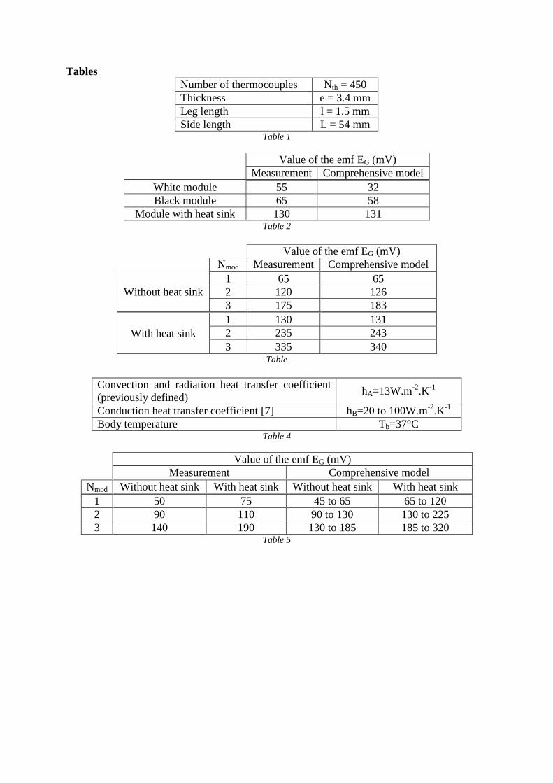
Table Captions Table 1: Specifications of the TM-450-0.8-3.0 thermoelectric module
Table 2: Initial comparison between measurements on a hot plate and the thermoelectric model
at Ta = 22°C and Th = 36°C
Table 3: Second comparison between measurements conducted on a hot plate and the thermoelectric model at Ta=22°C and Th=36°C
Table 4: Quantities used to calculate model parameters
Table 5: Comparison between measurements conducted on a human arm at Ta=22°C and
quantities output by the model

Figures
Figure1
Figure2
Figure3

Figure4
Figure5
Figure6
Figure7

Figure8
Figure9
Figure10

Figure11
Figure12
Figure13

Figure14
Figure15
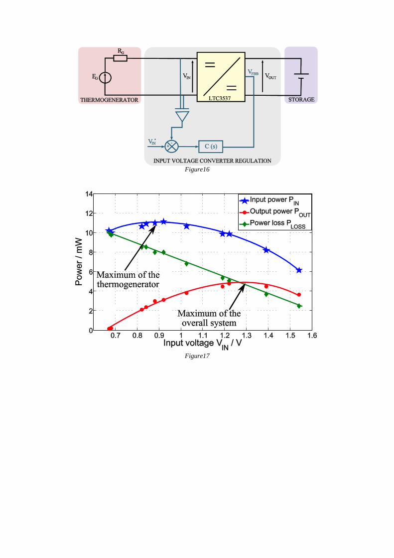
Figure16
Figure17
Tables
Number of thermocouples Nth = 450
Thickness e = 3.4 mm
Leg length l = 1.5 mm
Side length L = 54 mm Table 1
Value of the emf EG (mV)
Measurement Comprehensive model
White module 55 32
Black module 65 58
Module with heat sink 130 131 Table 2
Value of the emf EG (mV)
Nmod Measurement Comprehensive model
Without heat sink
1 65 65
2 120 126
3 175 183
With heat sink
1 130 131
2 235 243
3 335 340 Table
Convection and radiation heat transfer coefficient
(previously defined) hA=13W.m
-2.K
-1
Conduction heat transfer coefficient [7] hB=20 to 100W.m-2
.K-1
Body temperature Tb=37°C Table 4
Value of the emf EG (mV)
Measurement Comprehensive model
Nmod Without heat sink With heat sink Without heat sink With heat sink
1 50 75 45 to 65 65 to 120
2 90 110 90 to 130 130 to 225
3 140 190 130 to 185 185 to 320 Table 5