tools for imrt qa - american association of physicists in ... · tools for imrt qa n. dogan, ph.d...
TRANSCRIPT
Tools for IMRT QAN. Dogan, Ph.D
Department of Radiation OncologyVirginia Commonwealth University
Medical College of Virginia HospitalsRichmond, VA, USA

N. Dogan /July 2005 N. Dogan
Objectives• To identify the QA tasks involving
IMRT• To describe the QA tools for all
aspects of IMRT process• To explain the limitations of the current
IMRT QA tools• To compare the IMRT QA tools and
techniques
N. Dogan /July 2005 N. Dogan
QA tasks for IMRT • Machine QA- Acceptance and routine QA of
the MLC for IMRT delivery - dosimetric and geometric characteristics
• Algorithm QA for IMRT - QA of planning system and data consistency with machine
• Patient Specific QA – prove plan works1D and 2D dosimetry of treatment components such IM beams and segments3D dosimetry of entire treatment delivery
• Post Treatment QA• Log-file analysis

N. Dogan /July 2005 N. Dogan
IMRT QA Tools
• Detectors• Phantoms• Scanners• Dosimetric Analysis Tools

N. Dogan /July 2005 N. Dogan
Detector Requirements for IMRT QA• Geometric and dosimetric accuracy• Volumetric simultaneously integrating dosimeter
to faithfully quantify the dose delivered over the total time of treatment
• Good spatial resolution, tissue equivalent response
• Ability to provide 3-D information• Portability to multiple phantoms• Ease of use• Sufficiently large dynamic range and be
insensitive to photon energy spectrum and dose rate response which is independent of the energy spectrum
N. Dogan /July 2005 N. Dogan
IMRT QA ToolsDetectors• Many of them available for IMRT
measurements• Necessary to characterize the detector
response for both static and dynamic fields for linearity
• Need to be calibrated for absolute measurements
• Need to determine stem and cable effects

N. Dogan /July 2005 N. Dogan
IMRT QA ToolsDetectors• Need to determine energy dependence
and angular response• Small field detectors required for small
field characterizationSensitive to positionDetector should be smaller than homogeneous region of dose to be measured
• Assess electrometer response

N. Dogan /July 2005 N. Dogan
IMRT QA ToolsDetectors, cont.• Need to determine necessary
resolutiondepends on the resolution of the beamlet grid that is used for planning and sequencing fields for delivery Chambers with the smaller volumes are more sensitive to position and will have a higher response when positioned at an opposing leaf pair junction and between adjacent leaves
Dose (cGy)
70605040302010
Poor detectorposition
More stablemeasurementpoint
Courtesy of Jean Moran, UofM

N. Dogan /July 2005 N. Dogan
IMRT QA Tools
1-D and 2-D Detectors• Ion chamber (1-D)• TLDs and MOSFETs (1-D)• Detector arrays (2-D)• Film (2-D)
RadiographicRadiochromic
• Gels (3-D)

N. Dogan /July 2005 N. Dogan
Small 1-D Detectors
0.0019
NA
NA
0.3
0.015
0.009
Volume(cm3)
0.45
0.4
0.73
NA
0.2
0.6
Diameter(cm)
< resolution than diodes, dose rate dependence, expensive
Diamond
Non-linear dose response for <30 cGy
MOSFET
Stereotactic diode
p-type Si diode
Over-respond to low energy photons
Martens et al. 2000
Pinpoint chamber
Poorer resolution than diodesMicro-chamber
DisadvantagesDetector
IMRT QA Tools
N. Dogan /July 2005 N. Dogan
IMRT QA ToolsIon Chamber• Advantages
Available in different shape and sizesDosimetric response is well understood.Absolute dose measurements – theory is well establish, they can be used as a benchmark standardEasy to calibrate
N. Dogan /July 2005 N. Dogan
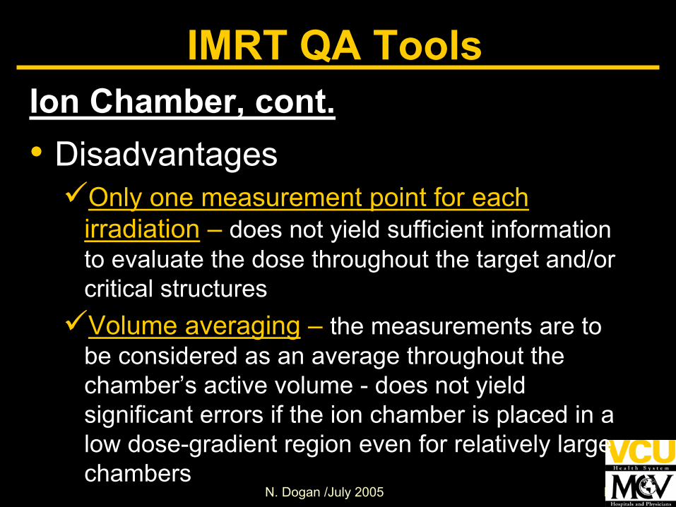
IMRT QA ToolsIon Chamber, cont.• Disadvantages
Only one measurement point for each irradiation – does not yield sufficient information to evaluate the dose throughout the target and/or critical structuresVolume averaging – the measurements are to be considered as an average throughout the chamber’s active volume - does not yield significant errors if the ion chamber is placed in a low dose-gradient region even for relatively large chambers

N. Dogan /July 2005 N. Dogan
IMRT QA ToolsIon Chamber volume averaging, cont.
D.A. Low et al. “Ionization chamber volume averaging effects in dynamic intensity modulated radiation therapy beams, Med. Phys.30(7): 1706-1711 (2003
Micro cham: 0.009cc
PTW: 0.125cc
Farmer:0.65cc
N. Dogan /July 2005 N. Dogan
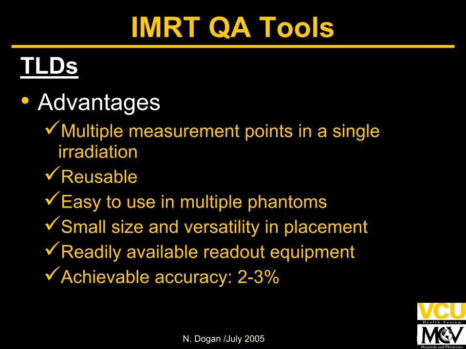
IMRT QA ToolsTLDs• Advantages
Multiple measurement points in a single irradiationReusableEasy to use in multiple phantomsSmall size and versatility in placementReadily available readout equipmentAchievable accuracy: 2-3%

N. Dogan /July 2005 N. Dogan
IMRT QA ToolsTLDs• Disadvantages
Requires calibration to determine calibration factor for each TLD chipRequires calibration of subset of TLD chips for each measurementTLD reader response and oven temperature should me routinely monitored to maintain consistent TLD responseAutomatic reader recommended for IMRT field verification due to large number of TLDsrequired for verification in a plane (60 or more) – inefficient for routine IMRT QA
N. Dogan /July 2005 N. Dogan
IMRT QA Tools
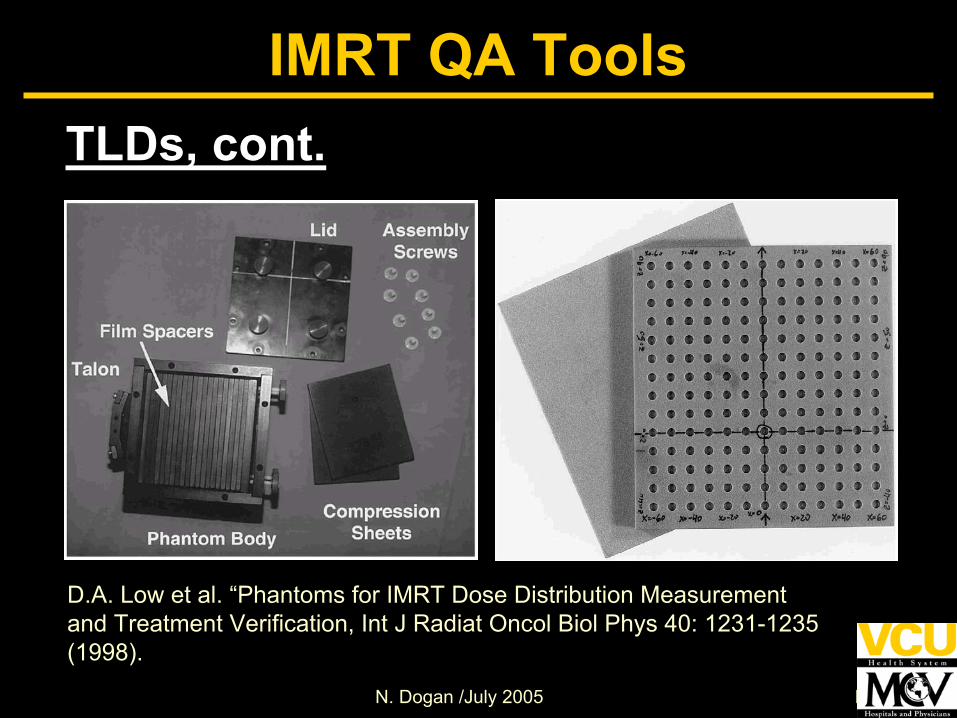
D.A. Low et al. “Phantoms for IMRT Dose Distribution Measurementand Treatment Verification, Int J Radiat Oncol Biol Phys 40: 1231-1235 (1998).
TLDs, cont.

N. Dogan /July 2005 N. Dogan
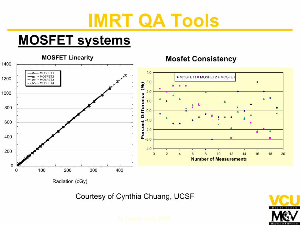
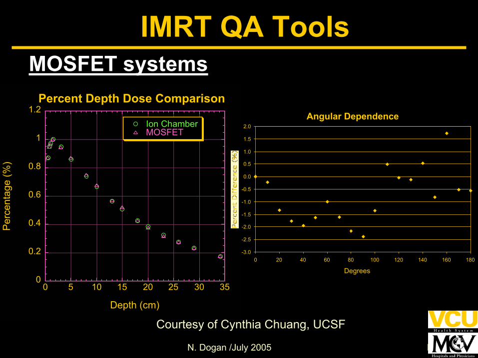
IMRT QA ToolsMOSFET systems• Advantages
Excellent spatial resolution – small size (~0.04mm2)Multiple detectors can be irradiated simultaneouslyAutomatic and immediate readoutCan be re-used immediatelyLinear dose response > 30 cGy Response independent of depthCommercially available phantoms to accommodate the small detectors

N. Dogan /July 2005 N. Dogan
IMRT QA Tools
MOSFET systems• Disadvantages
Decrease linearity for < 30 cGy – limited to high dose applicationsOver-response for the phantom scatter factor for small fields Specific application and measurement conditions should be carefully assessed and the detector should be used in the appropriate dose range

N. Dogan /July 2005 N. Dogan
IMRT QA ToolsMOSFET systems
Reader
Bias Box
MOSFET
TNRD50 system
Courtesy of Cynthia Chuang, UCSFAn axial image of MOSFET
phantom
N. Dogan /July 2005 N. Dogan
0
200
400
600
800
1000
1200
1400
0 100 200 300 400
MOSFET Linearity
MOSFET1MOSFET2MOSFET3MOSFET4
Radiation (cGy)
-4.0
-3.0
-2.0
-1.0
0.0
1.0
2.0
3.0
4.0
0 2 4 6 8 10 12 14 16 18 20Number of Measurements
MOSFET1 MOSFET2 MOSFET3
Mosfet Consistency
IMRT QA Tools
Courtesy of Cynthia Chuang, UCSF
MOSFET systems
N. Dogan /July 2005 N. Dogan
0
0.2
0.4
0.6
0.8
1
1.2
0 5 10 15 20 25 30 35
Percent Depth Dose Comparison
Ion ChamberMOSFET
Per
cent
age
(%)
Depth (cm)
Angular Dependence
-3.0
-2.5
-2.0
-1.5
-1.0
-0.5
0.0
0.5
1.0
1.5
2.0
0 20 40 60 80 100 120 140 160 180
Degrees
IMRT QA Tools
Courtesy of Cynthia Chuang, UCSF
MOSFET systems

N. Dogan /July 2005 N. Dogan
Cal. 1.64 GyMeas. 1.72 GyDiff 4.6 %
Cal. 0.70 GyMeas. 0.68 GyDiff - 2.8 %
IMRT QA Tools
Calc. 2.18 GyMeas. 2.09 GyDiff –4.35%
Calc. 1.37 GyMeas. 1.42 GyDiff –3.52%
Calc. 0.81 GyMeas. 0.78 GyDiff –3.45%
Courtesy of
Cynthia Chuang, UCSF

N. Dogan /July 2005 N. Dogan
Current IMRT QA Tools
2-D Detectors• Film
RadiographicRadiochromic
• Beam imaging system, CCD, SLIC, AMFPI• 2-D Detector arrays
Diode array (Mapcheck) Ion chamber
• Active matrix flat panel detector (AMFPD)
N. Dogan /July 2005 N. Dogan
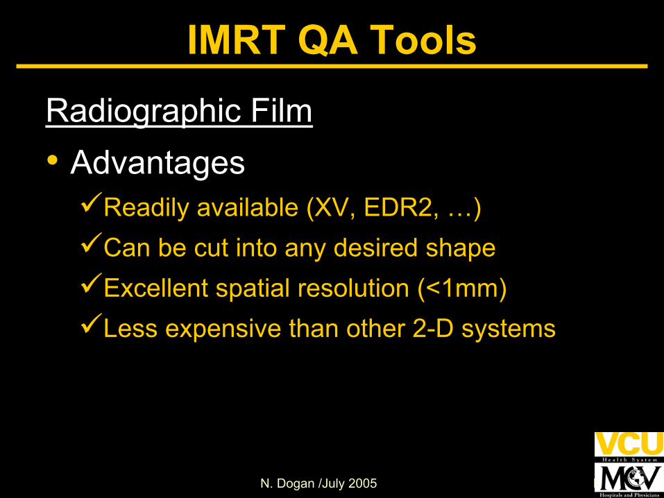
IMRT QA ToolsRadiographic Film• Advantages
Readily available (XV, EDR2, …)Can be cut into any desired shapeExcellent spatial resolution (<1mm)Less expensive than other 2-D systems
N. Dogan /July 2005 N. Dogan
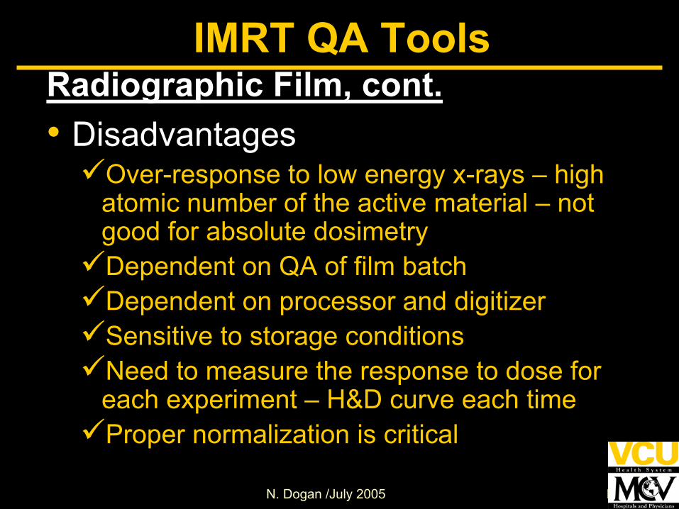
IMRT QA ToolsRadiographic Film, cont.• Disadvantages
Over-response to low energy x-rays – high atomic number of the active material – not good for absolute dosimetryDependent on QA of film batchDependent on processor and digitizerSensitive to storage conditionsNeed to measure the response to dose for each experiment – H&D curve each timeProper normalization is critical
N. Dogan /July 2005 N. Dogan
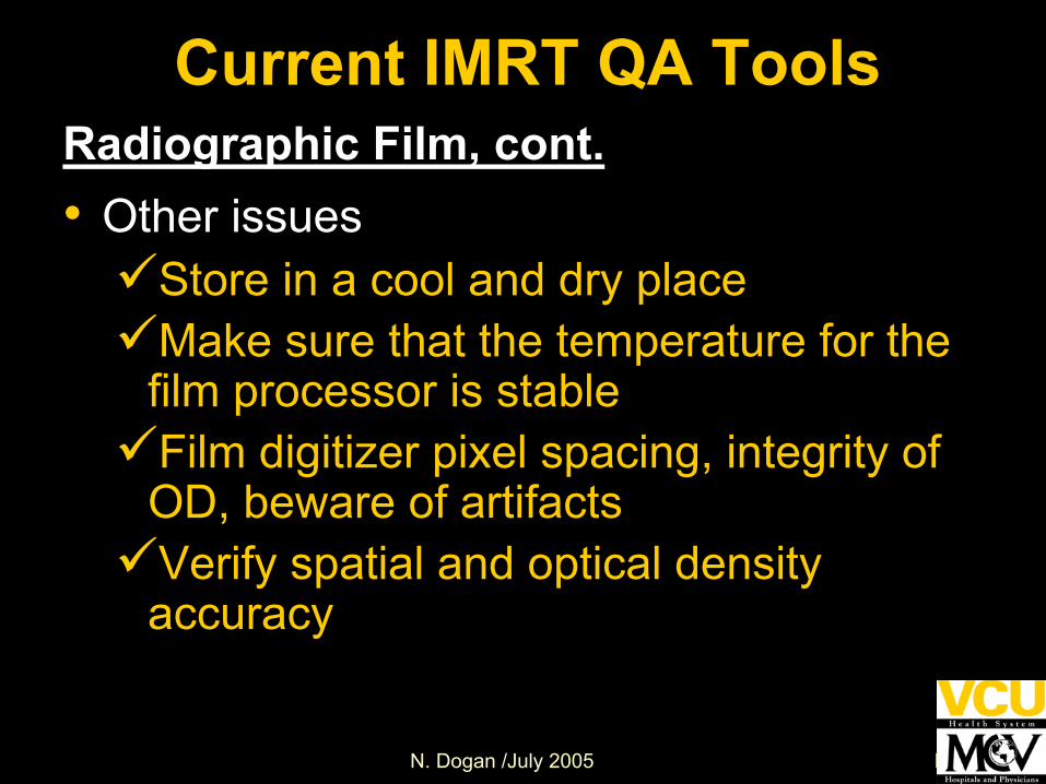
Current IMRT QA ToolsRadiographic Film, cont.• Other issues
Store in a cool and dry placeMake sure that the temperature for the film processor is stableFilm digitizer pixel spacing, integrity of OD, beware of artifactsVerify spatial and optical density accuracy
N. Dogan /July 2005 N. Dogan
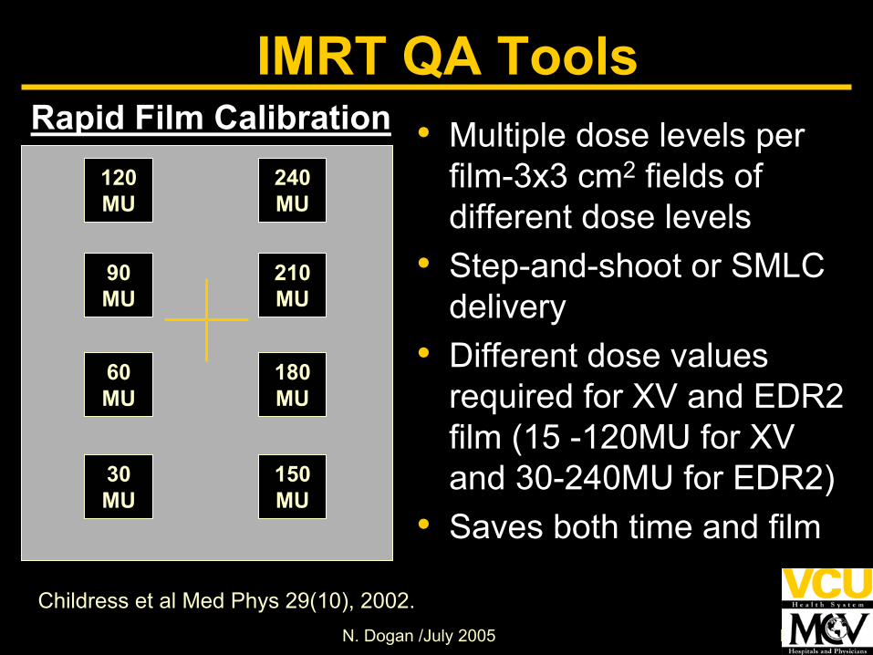
Rapid Film Calibration120MU
240MU
90MU
180MU
150MU
210MU
60MU
30MU
Childress et al Med Phys 29(10), 2002.
IMRT QA Tools• Multiple dose levels per
film-3x3 cm2 fields of different dose levels
• Step-and-shoot or SMLC delivery
• Different dose values required for XV and EDR2 film (15 -120MU for XV and 30-240MU for EDR2)
• Saves both time and film

N. Dogan /July 2005 N. Dogan
XV vs. EDR Film
0.0
0.5
1.0
1.5
2.0
2.5
3.0
3.5
0.0 100.0 200.0 300.0 400.0 500.0 600.0
XV2, 6 MV
XV2, 15 MV
EDR2, 6 MV
EDR2, 15 MVNet
Opt
ical
Den
sity
Dose (cGy)Chetty and Charland 2002
PMB 47: 3629-3641Dogan et al. 2002 PMB 47: 4121-4130
EDR
XV
IMRT QA Tools
0
0.2
0.4
0.6
0.8
1
1.2
1.4
1.6
0 50 100 150 200 250 300 350
Dose (cGy)O
ptic
al D
ensi
ty
Co60-EDR2 6MV-EDR2
10MV-EDR2 18MV-EDR2
Depth-corrected H&D

N. Dogan /July 2005 N. Dogan
Dogan et al. 2002 PMB 47: 4121-4130
EDR
XV
IMRT QA Tools
Depth-corrected H&D curves
0
0.2
0.4
0.6
0.8
1
1.2
1.4
1.6
0 50 100 150 200 250 300 350Dose (cGy)
Opt
ical
Den
sity
6MV-EDR2-Depth corrected6MV-EDR2-Regular
0
0.2
0.4
0.6
0.8
1
1.2
1.4
1.6
0 50 100 150 200 250 300 350
Dose (cGy)
Opt
ical
Den
sity
18MV-EDR2-Depth corrected18MV-EDR2-Regular

N. Dogan /July 2005 N. Dogan
Ion Chamber
Film- depth corrected H&D
Film regular H&D
(a) (b)Ion chamber and EDR2 film depth-dose curves for a) 6 x 6 cm2, b) 14 x 14 cm2 films for 10 MV beam. Films were positioned parallel to the beam and OD to dose conversion was done using regular and depth-corrected H&D curves.
IMRT QA Tools
Dogan et al. 2002 PMB 47: 4121-4130
N. Dogan /July 2005 N. Dogan
IMRT QA Tools
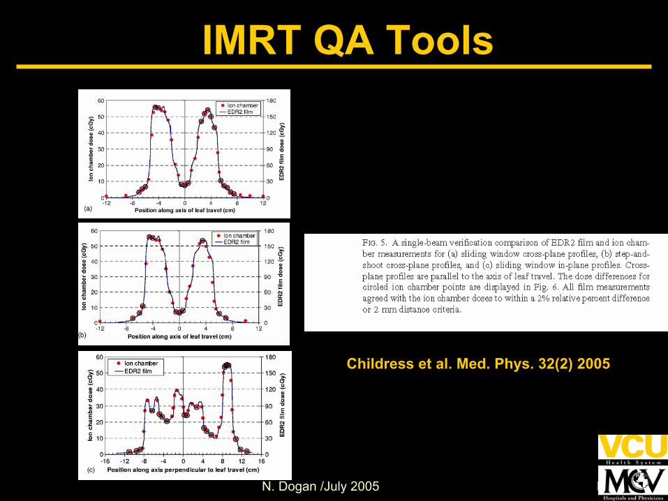
Childress et al. Med. Phys. 32(2) 2005
N. Dogan /July 2005 N. Dogan
IMRT QA ToolsAs compared to XV film, EDR2 film• has less dependence on the
processor, field size• less response to low energy photons• have better reproducibility and
agreement with ion chamber measurements
• can be used to measure a complete fraction of an IMRT treatment

N. Dogan /July 2005 N. Dogan
Radiographic Film: 2-D Dosimetric Measurements
Intensity mapfrom Opt System
Calculated
LeafSequencer
Measured
Calc-Meas
Courtesy of Jean Moran, UM
IMRT QA Tools

N. Dogan /July 2005 N. Dogan
DMLC field 14x14 cm2
at SSD =100 cm, 2 cm separated strips
• Using radiographic filmsIntensity-modulated pattern fieldCheck leaf position, acceleration, motion stability Check for hot and cold density Visual check
IMRT QA ToolsRadiographic Film: Routine DMLC QA

N. Dogan /July 2005 N. Dogan
IMRT QA ToolsFilm – Processor issues• Should do routine maintenance and quality
assurance – verify spatial intensity, characteristic response, noise due to large changes in optical density ( Dempsey et al, Med Phys, 26; 1721-1731, 1999).
• Should be warmed up prior to use• Should have appropriate amount of chemicals
- Several films should be run in advance• Should have stable temperature• Should have a consistent rate of feeding into
the processor

N. Dogan /July 2005 N. Dogan
IMRT QA ToolsFilm – Other Issues• Accurate positioning of the film in the
phantom – for the registration with treatment planning system
• Minimized errors by using a solid-water slab designed for film
• Have pins between slabs that puncture the film

N. Dogan /July 2005 N. Dogan
IMRT QA ToolsRadiochromic Film (RCF)• Advantages
No significant energy dependence –decreased sensitivity to low-energy photonsInsensitivity to visible lightVery high spatial resolution - well-suited for measurements in high-dose gradient fieldsSelf-developing – no developer or fixer is requiredEasy to handleTissue equivalent

N. Dogan /July 2005 N. Dogan
IMRT QA ToolsRadiochromic Film, cont.• Disadvantages
Takes a couple of hours for the color change to stabilize, and it may be necessary to wait up to two days before evaluating the filmSensitive to the air temperature and humidityUltraviolet light may cause a color change without exposure to ionizing radiationSize, availability, and costNon-uniform response to radiation – double exposure technique minimizes this effectIssues with thermal history, wavelength dependence, and local sensitivity of the film
N. Dogan /July 2005 N. Dogan
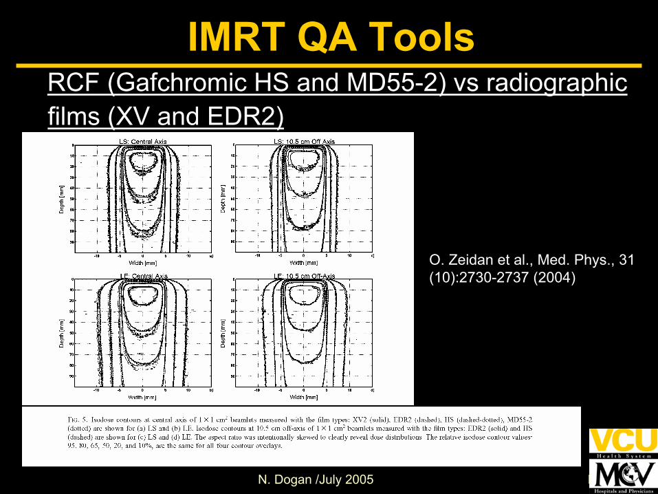
IMRT QA ToolsRCF (Gafchromic HS and MD55-2) vs radiographic films (XV and EDR2)
O. Zeidan et al., Med. Phys., 31 (10):2730-2737 (2004)

N. Dogan /July 2005 N. Dogan
IMRT QA ToolsRCF profiles vs. Ion chamber
J. Dempsey et al., Med. Phys., 27 (10):2462-2475 (2000)
N. Dogan /July 2005 N. Dogan
IMRT QA ToolsRCF – digitizer issues• Response of the digitizer
• Light source characteristics• DesignGluckman et al, Med Phys, 29(8); 1839-1846, 2002.
N. Dogan /July 2005 N. Dogan
Other 2-D systems• Beam imaging system, CCD, SLIC,
Amorphous silicon flat panel detector (AMFPD)
EPID systems attached to gantryInvestigated more for pre-treatment QA currently
• 2-D Detector arraysDiode array (e.g; MapCheck) Ion chamber (e.g; LA48 linear array)
IMRT QA Tools
N. Dogan /July 2005 N. Dogan
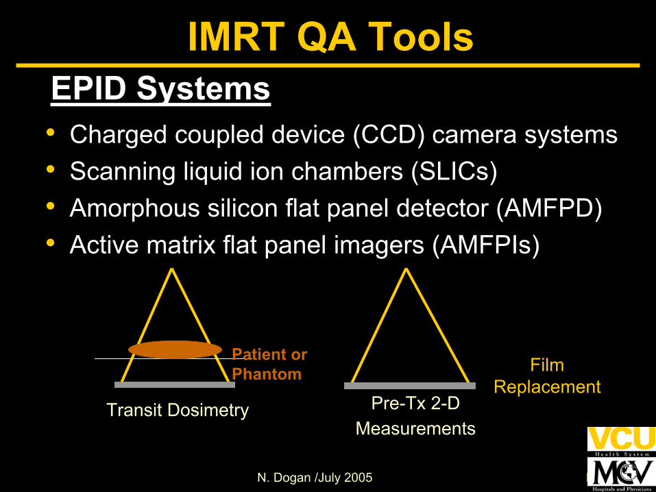
EPID Systems• Charged coupled device (CCD) camera systems• Scanning liquid ion chambers (SLICs)• Amorphous silicon flat panel detector (AMFPD)• Active matrix flat panel imagers (AMFPIs)
Transit Dosimetry
Patient orPhantom
Pre-Tx 2-D Measurements
FilmReplacement
IMRT QA Tools

N. Dogan /July 2005 N. Dogan
EPID Systems• aS500 EPID
1 mm copper platePhosphor scintillating layer (Kodak Lanex Fast B –Gd2O2S:Tb, 70 mg/cm3)Array of photodiodesAmorphous Silicon panel each pixel consists of:
Light sensitive photodiode Thin film transistor
16-bit ADC
Munro et. al, Med. Phys. 25, 1998
IMRT QA Tools

N. Dogan /July 2005 N. Dogan
EPIDsAdvantages• Many centers have installed EPIDs and being
primarily used for patient-specific pretreatment field verification and MLC QA
Logical extension to investigate dosimetric applications• Mounted to linear accelerator - known
geometry with respect to the beamDetector sag must be accounted for at different gantry anglesPositioning reproducibility important
• Real time digital evaluationNo processor, data acquisition takes less time
IMRT QA Tools
N. Dogan /July 2005 N. Dogan
• EPIDs were primarily designed for patient localization
High resolution, good contrast imagesAdditional dose to the patient should be minimized
• The conversion of imager response to dose is complex
Imaging system dependent
• Other problemsGhostingLag
IMRT QA ToolsEPIDs - Challenges

N. Dogan /July 2005 N. Dogan
• Imager response must be calibrated to a standard
• Absolute calibration to ion chamber at a point over a ROI
E.g. ion chamber in a mini-phantom or slab at same SDD as EPID
• 2-D calibration to actual beam distribution at the imager plane
Can be measured with film or a diode array
IMRT QA ToolsEPIDs – Dose determination

N. Dogan /July 2005 N. Dogan
Factors for EPID Response• Water-equivalent depth of the
detector• Field size dependence and scatter
properties within the imager• Short- and long-term reproducibility• Dose rate• Energy dependence• Spatial integrity
IMRT QA Tools

N. Dogan /July 2005 N. Dogan
EPID: DMLC measurements
Pasma Med Phys 26: 2373-2378 (2376) 1999
PredictedEPIDIon Chamber+
Discrepancies in the penumbra region (up to 10%)
Overall: Good agreement
10 MV 25 MV
IMRT QA Tools
N. Dogan /July 2005 N. Dogan
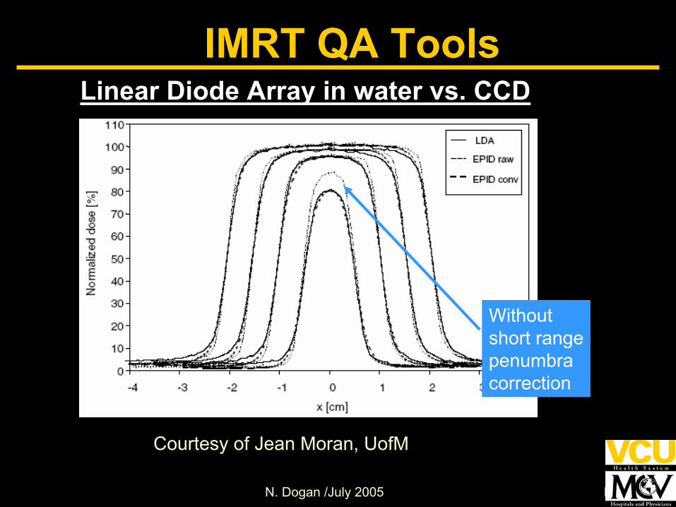
Withoutshort rangepenumbra correction
Linear Diode Array in water vs. CCD
Courtesy of Jean Moran, UofM
IMRT QA Tools

N. Dogan /July 2005 N. Dogan
Dose Determination using EPID (SLIC)
Chang et al., Int J Radiat Oncol Phys 47: 231-240 (p. 233)
IMRT QA Tools

N. Dogan /July 2005 N. Dogan
Agreement : Within +/- 2 cGy
Calculated (Calculated – Measured)
Courtesy of Jean Moran, UofM
IMRT QA ToolsCalculation vs. measured using AMFPD for DMLC

N. Dogan /July 2005 N. Dogan
• EPIDs can provide a much-needed replacement for pre-tx QA film dosimetry
Only if proper QA of the EPID is establishedNeed better understanding of regions where EPIDsare inadequate for dosimetrySystems must be verified at more centers against accepted QA methods such as film and ion chamberAdditional software is required before more facilities can do proper validation of the methods (Software must be commissioned)Can be part of a comprehensive QA program in conjunction with other methods such as computational checks (monitor programs, log file analysis, etc.)
IMRT QA Tools

N. Dogan /July 2005 N. Dogan
IMRT QA ToolsGel Dosimeters
• Advantages3-D information in one irradiationEnergy and dose-rate independentHigh sensitivity and linear responseCumulativeGel density can be changed - Ideal for anthropomorphic phantomsNear tissue equivalentMultiple readout techniques (MR, optical-CT)New gel formulations and readers commercially available
N. Dogan /July 2005 N. Dogan
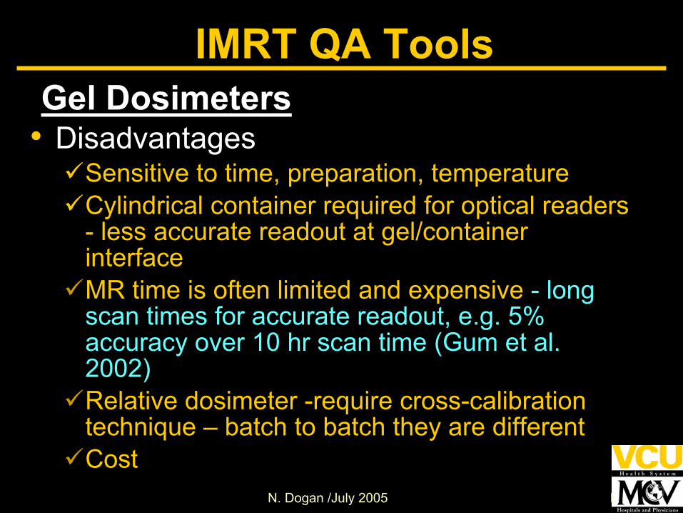
IMRT QA ToolsGel Dosimeters
• DisadvantagesSensitive to time, preparation, temperatureCylindrical container required for optical readers - less accurate readout at gel/container interfaceMR time is often limited and expensive - long scan times for accurate readout, e.g. 5% accuracy over 10 hr scan time (Gum et al. 2002)Relative dosimeter -require cross-calibration technique – batch to batch they are differentCost
N. Dogan /July 2005 N. Dogan
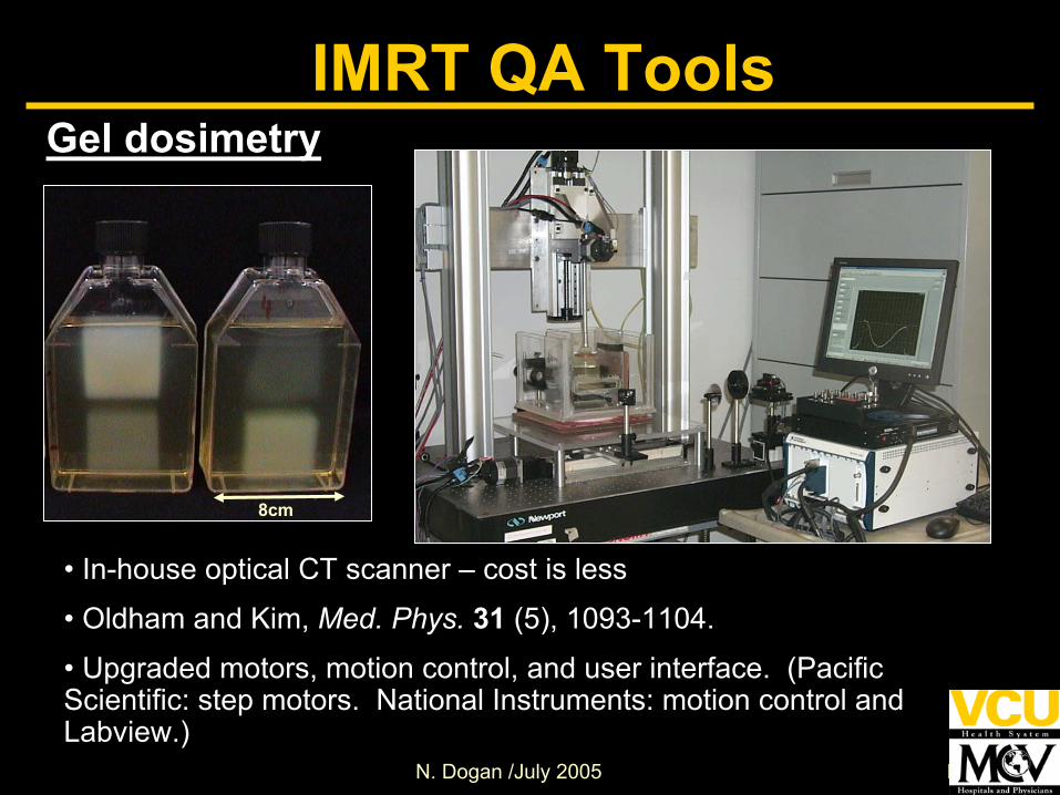
• In-house optical CT scanner – cost is less
• Oldham and Kim, Med. Phys. 31 (5), 1093-1104.
• Upgraded motors, motion control, and user interface. (Pacific Scientific: step motors. National Instruments: motion control and Labview.)
IMRT QA ToolsGel dosimetry
8cm

N. Dogan /July 2005 N. Dogan
Gels: Optical Density to Dose Calibration
• 6 Beam calibration irradiation• BANG gel phantom diameter 17.4cm
IMRT QA Tools
Courtesy of Mark Oldham, Duke University

N. Dogan /July 2005 N. Dogan
• Five Field Prostate IMRT
• Re-computed for a 3 L BANG gel dosimeter.
•Dmax scaled to 1.8 Gy to fit dynamic range of optical scanner
• BANGkitTM from MGS Research. Optical-CT @ 1x1x3mm, 5hours
Courtesy of Mark Oldham, Duke University
IMRT QA ToolsGel Dosimeters
N. Dogan /July 2005 N. Dogan
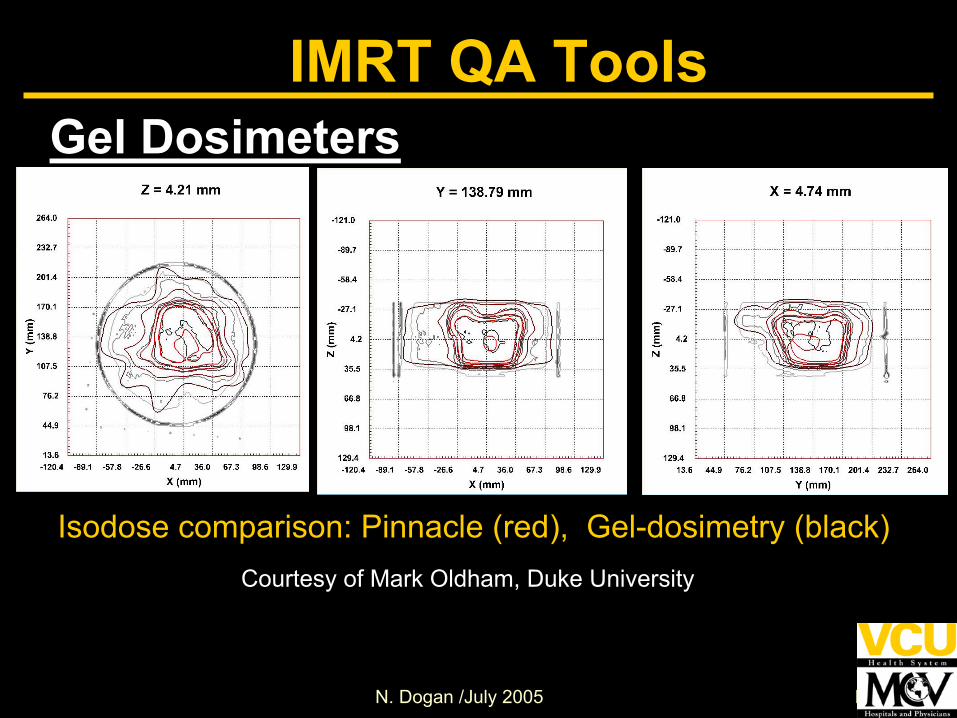
Isodose comparison: Pinnacle (red), Gel-dosimetry (black)Courtesy of Mark Oldham, Duke University
IMRT QA ToolsGel Dosimeters

N. Dogan /July 2005 N. Dogan
IMRT QA ToolsGel Dosimeters
Gum, et al. “Preliminary study on the use of an inhomogeneous anthropomorphic Fricke gel phantom and 3D magnetic resonance dosimetry for verification of IMRT plans ,” Phys Med Biol 47; N67-77 2002.

N. Dogan /July 2005 N. Dogan
Phantoms for IMRT Measurements
• multiple phantoms for commissioning • Fiducials for reproducible setup of
phantom and detectors• User-customized for different detectors –
allow special holders• Simple vs. anthropomorphic• Homogeneous or heterogeneous
IMRT QA Tools
N. Dogan /July 2005 N. Dogan
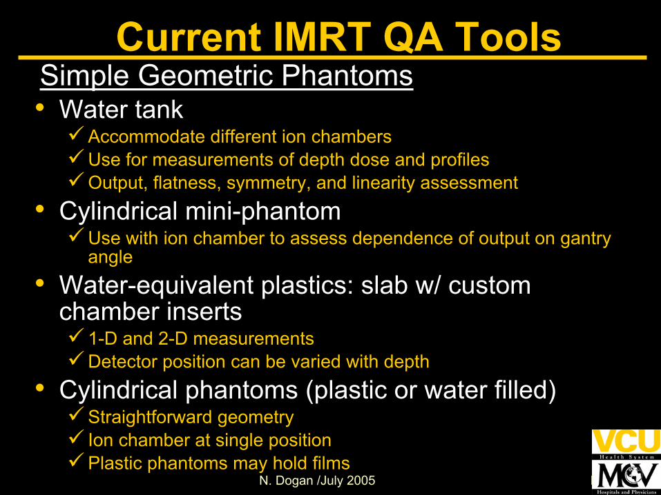
• Water tankAccommodate different ion chambersUse for measurements of depth dose and profilesOutput, flatness, symmetry, and linearity assessment
• Cylindrical mini-phantomUse with ion chamber to assess dependence of output on gantry angle
• Water-equivalent plastics: slab w/ custom chamber inserts
1-D and 2-D measurementsDetector position can be varied with depth
• Cylindrical phantoms (plastic or water filled)Straightforward geometryIon chamber at single positionPlastic phantoms may hold films
Current IMRT QA ToolsSimple Geometric Phantoms
N. Dogan /July 2005 N. Dogan
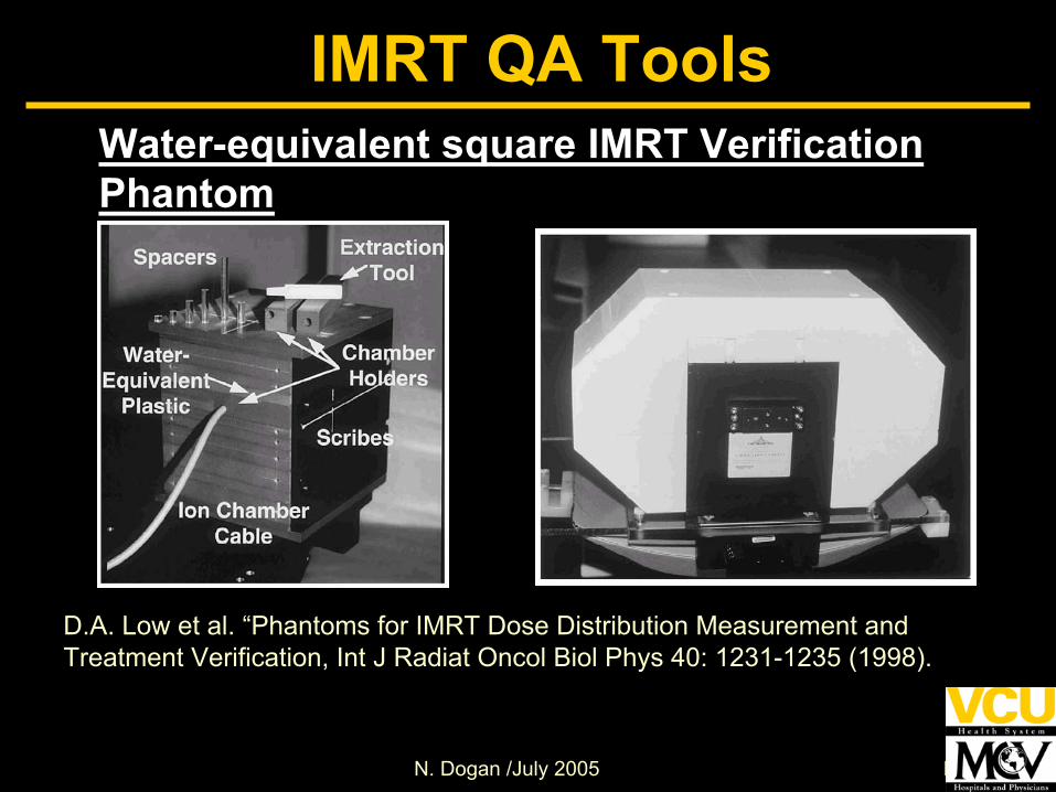
Water-equivalent square IMRT Verification Phantom
D.A. Low et al. “Phantoms for IMRT Dose Distribution Measurement and Treatment Verification, Int J Radiat Oncol Biol Phys 40: 1231-1235 (1998).
IMRT QA Tools

N. Dogan /July 2005 N. Dogan
A Cylindrical Phantom containing movable ion chamber
Current IMRT QA Tools
L. Xing et al. “Dosimetric verification of a commercial inverse treatment planning system, Phys. Med. Biol. 44: 463-478 (1998).

N. Dogan /July 2005 N. Dogan
A cylindrical Plastic PhantomDetector
IMRT QA Tools
N. Dogan /July 2005 N. Dogan
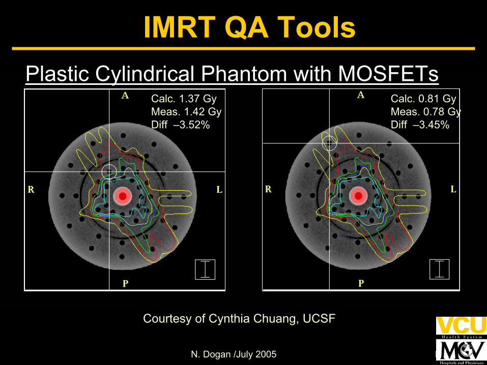
Calc. 1.37 GyMeas. 1.42 GyDiff –3.52%
Calc. 0.81 GyMeas. 0.78 GyDiff –3.45%
Courtesy of Cynthia Chuang, UCSF
Plastic Cylindrical Phantom with MOSFETs
IMRT QA Tools
N. Dogan /July 2005 N. Dogan
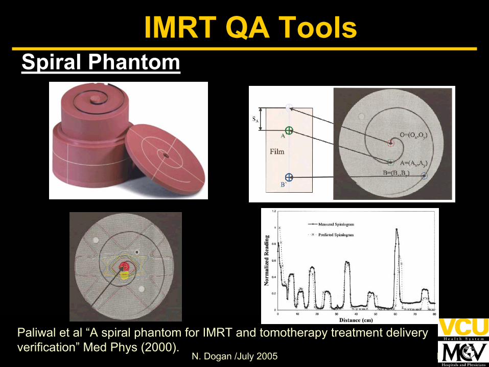
Spiral Phantom
Paliwal et al “A spiral phantom for IMRT and tomotherapy treatment delivery verification” Med Phys (2000).
IMRT QA Tools
N. Dogan /July 2005 N. Dogan
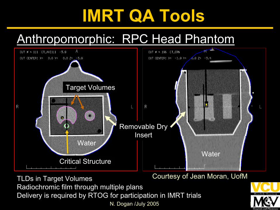
Anthropomorphic: RPC Head Phantom
Target Volumes
Critical Structure
TLDs in Target VolumesRadiochromic film through multiple plansDelivery is required by RTOG for participation in IMRT trials
Removable DryInsert
WaterWater
IMRT QA Tools
Courtesy of Jean Moran, UofM

N. Dogan /July 2005 N. Dogan
Dosimetric Analysis Tools
• Provide a comprehensive and quantitative comparison between two dose distributions
• Different ones available• Important to know the limitations
IMRT QA Tools
N. Dogan /July 2005 N. Dogan
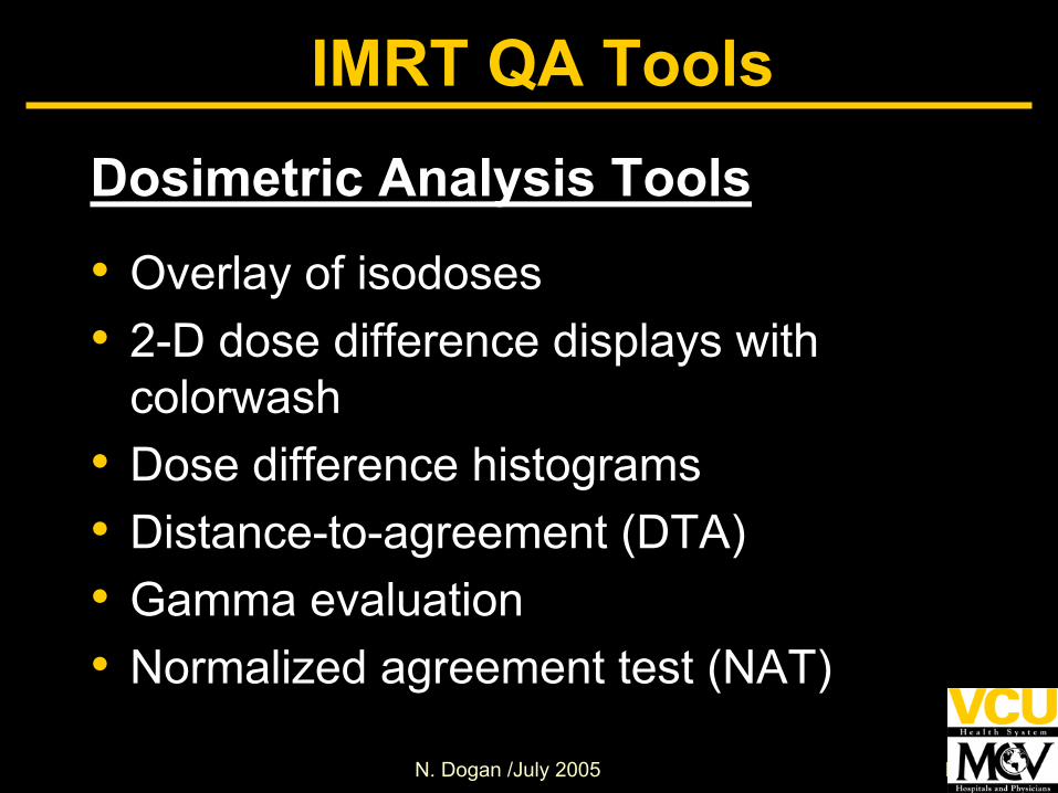
Dosimetric Analysis Tools
• Overlay of isodoses• 2-D dose difference displays with
colorwash• Dose difference histograms• Distance-to-agreement (DTA)• Gamma evaluation• Normalized agreement test (NAT)
IMRT QA Tools

N. Dogan /July 2005 N. Dogan
Isodose lines and Dose Difference Display
IMRT QA Tools
+/- 10%CalcsFilm
70 cGy60 cGy50 cGy20 cGy10 cGy
Courtesy of Jean Moran, UofM

N. Dogan /July 2005 N. Dogan
Dose difference display
• Useful in shallow dose gradients• Overly sensitive in steep dose gradients
– e.g.; a small spatial shift (due to experimental measurement errors) between two dose distributions yield large dose differences
IMRT QA Tools

N. Dogan /July 2005 N. Dogan
IMRT QA ToolsDose difference histogram and profiles

N. Dogan /July 2005 N. Dogan
Distance to Agreement (DTA)• Is the distance between a reference point
and the nearest point in the compared dose distribution that exhibits the same dose
• Is not overly sensitive in steep dose gradients
• In shallow dose gradients, a large DTA value may be computed even for relatively small dose differences
• May be hard to interpret
IMRT QA Tools
N. Dogan /July 2005 N. Dogan
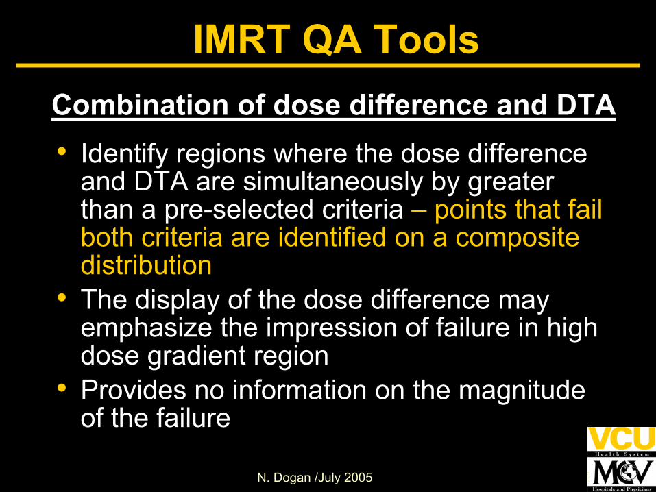
Combination of dose difference and DTA• Identify regions where the dose difference
and DTA are simultaneously by greater than a pre-selected criteria – points that fail both criteria are identified on a composite distribution
• The display of the dose difference may emphasize the impression of failure in high dose gradient region
• Provides no information on the magnitude of the failure
IMRT QA Tools
N. Dogan /July 2005 N. Dogan
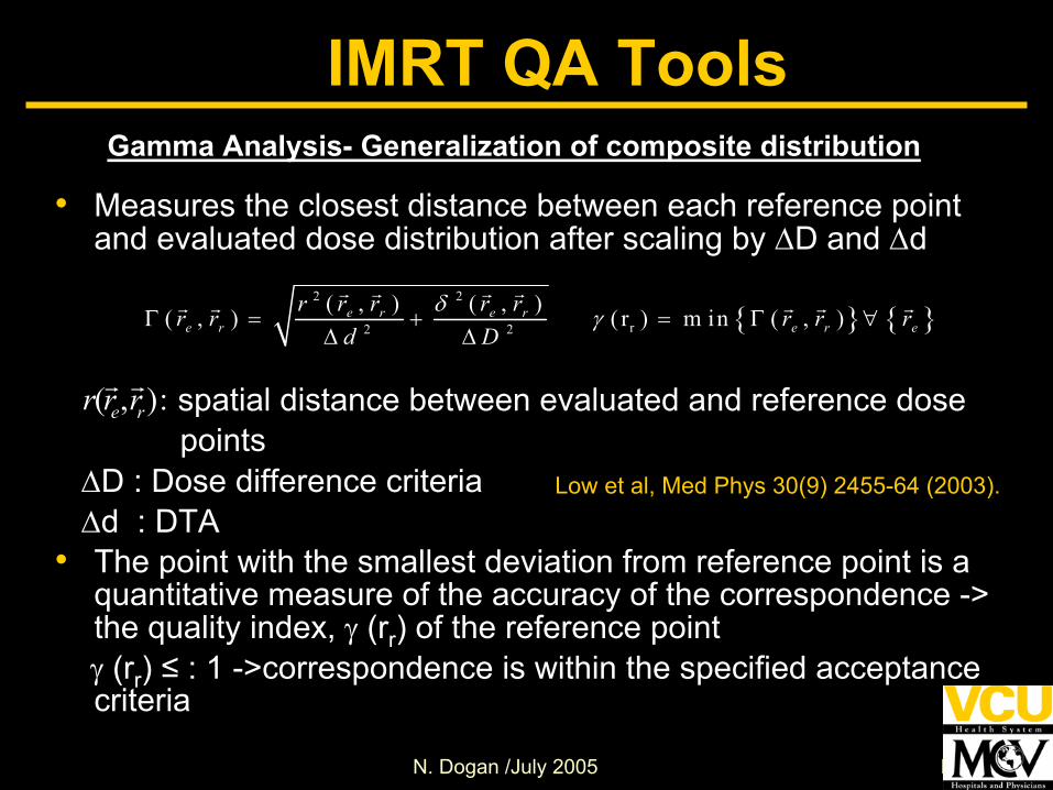
IMRT QA ToolsGamma Analysis- Generalization of composite distribution
• Measures the closest distance between each reference point and evaluated dose distribution after scaling by ∆D and ∆d
spatial distance between evaluated and reference dosepoints
∆D : Dose difference criteria∆d : DTA
• The point with the smallest deviation from reference point is a quantitative measure of the accuracy of the correspondence -> the quality index, γ (rr) of the reference pointγ (rr) ≤ : 1 ->correspondence is within the specified acceptance criteria
{ } { }2 2
r2 2
( , ) ( , )( , ) ( r ) m in ( , )e r e re r e r e
r r r r rr r r r rd D
δ γΓ = + = Γ ∀∆ ∆
( , ):e rr r r
Low et al, Med Phys 30(9) 2455-64 (2003).

N. Dogan /July 2005 N. Dogan
IMRT QA ToolsDose Difference and DTA
Dose Difference and DTA Analysis Summary
Dose Diff and DTA criteria : 2% ofDmax and 2mm
Points Checked = 5348Points Passed DTA = 5312Points Passed DD = 4363Points Passed Either = 5343Points Passed Both = 4332
99.3269 % of the points passed DTA
81.5819 % of the points passed DoseDiff
99.9065 % of the points passed eitherEither
81.0022 % of the points passed Both
Dose Difference Statistics Summary
Mean Dose Diff = 0.488805 0.877915
DTA SummaryMean DTA = 0.0477486 0.0747123
N. Dogan /July 2005 N. Dogan
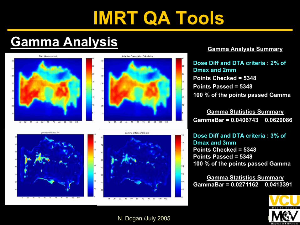
IMRT QA ToolsGamma Analysis
Gamma Analysis Summary
Dose Diff and DTA criteria : 2% ofDmax and 2mmPoints Checked = 5348 Points Passed = 5348 100 % of the points passed Gamma
Gamma Statistics SummaryGammaBar = 0.0406743 0.0620086
Dose Diff and DTA criteria : 3% ofDmax and 3mmPoints Checked = 5348 Points Passed = 5348 100 % of the points passed Gamma
Gamma Statistics SummaryGammaBar = 0.0271162 0.0413391

N. Dogan /July 2005 N. Dogan
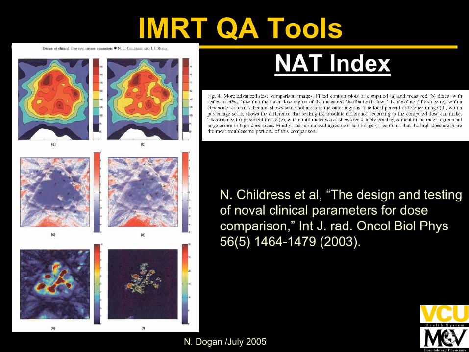
Normalized Agreement Test (NAT)IMRT QA Tools
( )1( )( )
sca le
indexsca le
N AT DAve NATNATAve D
δ= × −
=
• Is based on a 2D array of calculated image of NAT values derived from comparisons of measured and computed doses.
• Assumes that two dose distribution images are registered each other and NAT is calculated using
δ : lesser of Abs(∆D/ ∆Dm) or∆d/ ∆dm
Dscale: Di /Dmax
• NATindex represents the average deviation from the ∆Dm and ∆dm criteria for every dose pixel, ignoring the ones less than the set criteria
N. Childress et al, “The design and testing of noval clinical parameters for dose comparison,” Int J. rad. Oncol Biol Phys 56(5) 1464-1479 (2003).
N. Dogan /July 2005 N. Dogan
IMRT QA ToolsNAT Index
N. Childress et al, “The design and testing of noval clinical parameters for dose comparison,” Int J. rad. Oncol Biol Phys 56(5) 1464-1479 (2003).

N. Dogan /July 2005 N. Dogan
Other Analysis Tools• MU check software
In-house dose calcCommercial packages (e.g; Radcalc)Monte Carlo (e.g; Peregrine, EGS4, …) –Patient QA
• Software for Post-treatment QA Analysis of IMRT delivery log files (e.g; in-house analysis software, Argus IMRT QA package)
IMRT QA Tools

N. Dogan /July 2005 N. Dogan
∆=10%Superposition Monte Carlo
IMRT QA ToolsMC verification
N. Dogan /July 2005 N. Dogan
Summary• Multiple detectors and phantoms are
typically required for IMRT QA• Quantitative dose analysis tools are
necessary for proper evaluation of delivery - identify the cause of discrepancies between delivery and measurements
• Treatment planning vendors are starting to provide dosimetric evaluation tools
• Aware of the limitations of each tool
N. Dogan /July 2005 N. Dogan
Summary
• Verify that all equipment is functioning properly
Film processor, digitizerDetectors, cables, electrometers (automatic leakage correction)TLD reader, ovens
• Input/output to treatment planning system• Standardize measurement setup when
possible• Monitor software and hardware changes
and QA

N. Dogan /July 2005 N. Dogan
Summary• Measurements may show dosimetric
differences that planning systems may not model at this time – curved leaf ends
• Need to know the limits of the mechanical systems and interactions with controller and accelerator software for delivery
• Continued need for improvements to software for delivery system, measurement devices, phantoms, and dose analysis tools
N. Dogan /July 2005 N. Dogan
Acknowledgements
Jean Moran – U of MichiganCynthia Chuang – UCSFMark Oldham – Duke University