transportation research record 1290 9...
TRANSCRIPT
TRANSPORTATION RESEARCH RECORD 1290 9
Construction Design of the Dame Point Bridge
MAN-CHUNG TANG
Material quantities are usually not the most important items of such complex construction projects. A design with minimum materials does not necessarily represent the most efficient design. How a structure can be built is extremely important.
The main purpose of this paper is to describe how the bridge configuration and cable arrangement were modified to facilitate simpler construction and how the construction equipment was designed to make the operation more efficient.'
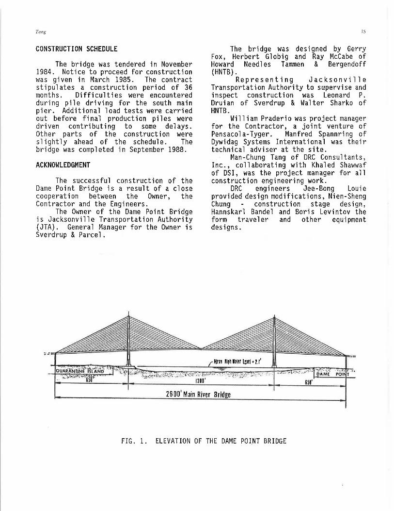
The Dame Point Bridge in J a c ks on v i ll e , Fl or i d a i s a cab l e -stayed bridge with a ma i nspan of 1300 feet. It is presently the longest span cablestayed bridge in the United States. It has a harp cable arrangement. The girder is 105 feet wide consisting of two solid edge girders. The bridge deck is supported by transverse floor beams framed into these edge girders. The deck slab varies from 9" to 2'-0". The floor beams are spaced at 17'-6" on centers.
The cables have Dywidag bar tendons grouted inside a steel pipe. This is the only cable-stayed bridge in North America that uses bar cables.
Towers are solid sections with cables enclosed in a crisscross pattern. The tower legs and columns are interconnected to each other by three bow-tie shaped cross-struts.
Construction of the deck was by castin-pl ace method which used specially designed form travelers. Construction progressed smoothly.
Aerodynamic stability during construction was studied based on results from wind tunnel tests. Special tiedowns were designed and installed to safeguard against possible buffeting of the bridge under hurricane.
President, DRC Consultants, Inc. 34-36 Union Street, Flushing, New York 11354.
INTRODUCTION
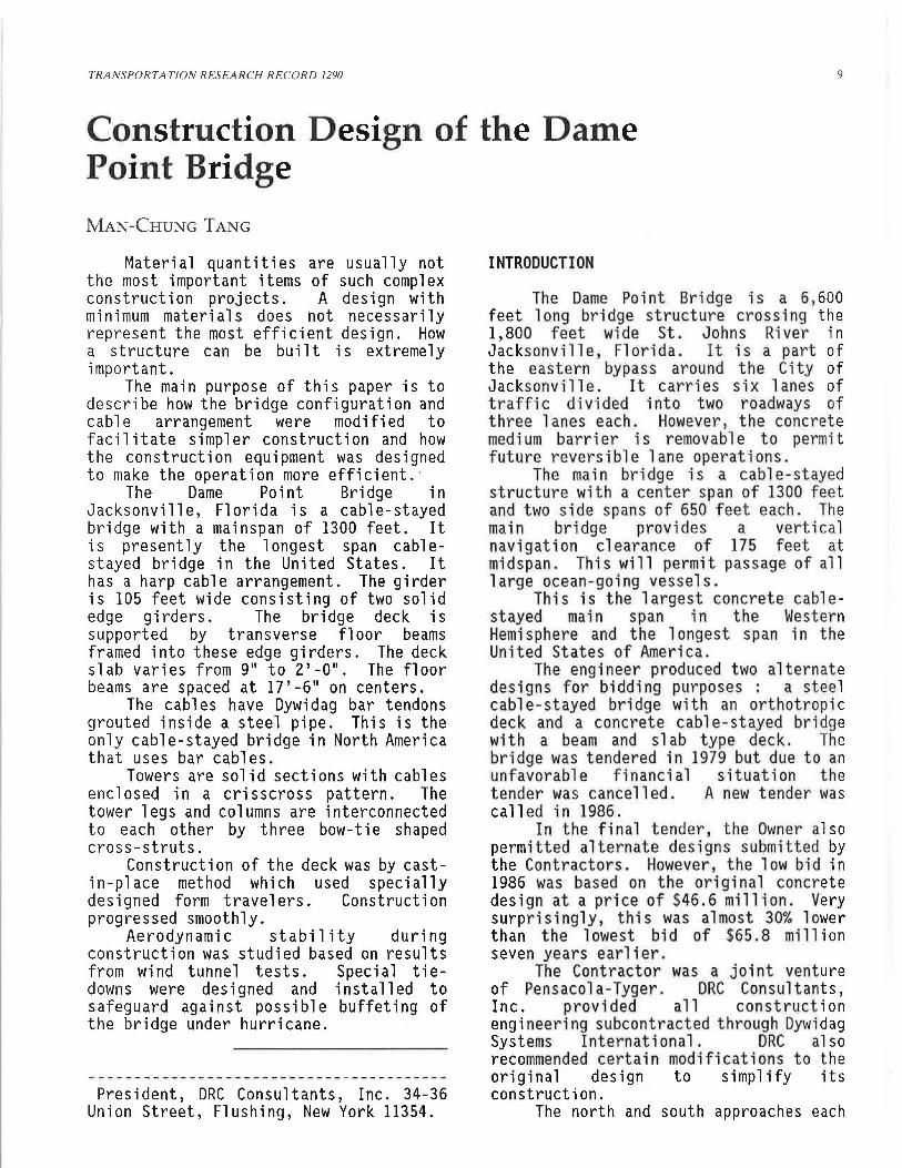
The Dame Point Bridge is a 6, 600 feet long bridge structure crossing the 1,800 feet wide St. Johns River in Jacksonville, Florida. It is a part of the eastern bypass around the City of Jacksonville. It carries six lanes of traffic divided into two roadways of three lanes each. However, the concrete medium barrier is removable to permit future reversible lane operations.
The main bridge is a cable-stayed structure with a center span of 1300 fee t and two side spans of 650 feet each. Th e main bridge provides a vertical navigation clearance of 175 feet at midspan. This will permit passage of all large ocean-going vessels.
This is the largest concrete cablestayed main span in the Western Hemisphere and the longest span in the United States of America.
The engineer produced two alternate designs for bidding purposes : a steel cable -stayed bridge with an orthotropic deck and a concrete cable -stayed bridge with a beam and slab type deck. Th e bridge was tendered in 1979 but due to an unfavorable financial situation the tender was cancelled. A new tender was called in 1986.
In the final tender, the Owner also permitted alternate designs submitted by the Contractors. However, the low bid in 1986 was based on the original concrete design at a price of $46.6 million. Very surprisingly , this was almost 30% lower than the lowest bid of $65.8 million seven years earlier.
The Contractor was a joint venture of Pensacola-Tyger. DRC Consultants, Inc. provided all construction engineering subcontracted through Dywidag Systems International. DRC also recommended certain modifications to the original design to simplify its construction.
The north and south approaches each
10
have two spans of 82 feet and 18 spans of 102 feet with precast I-girders and castin-pl ace deck slabs with portal type piers. This is an alternate to the original W-shaped solid piers. The contractor was McCarthy Brothers and redesign was provided by DRC Consultants, Inc.
This paper will concentrate on the construction of the cable-stayed main span only.
CHARACTERISTICS OF THE MAIN BRIDGE
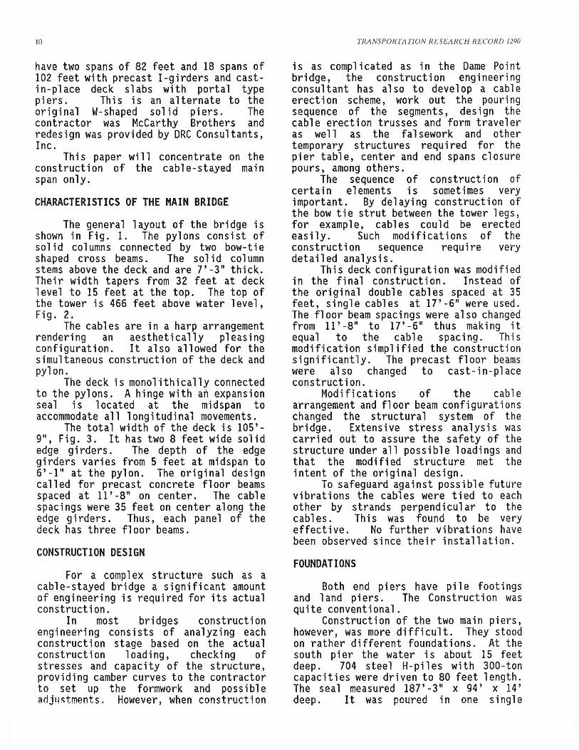
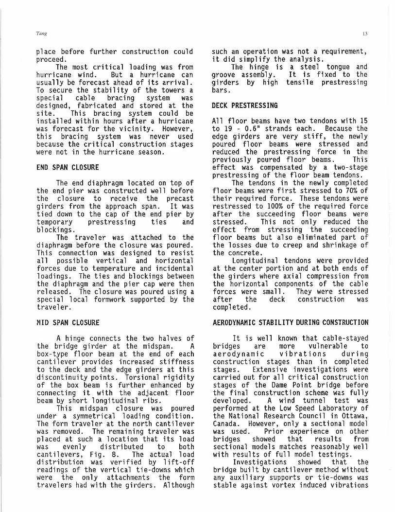
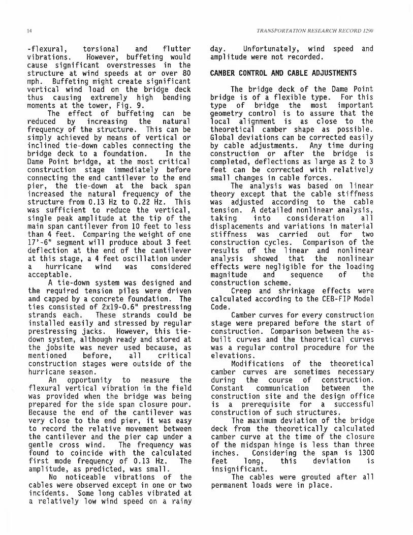
The general layout of the bridge is shown in Fig. 1. The pylons consist of solid columns connected by two bow-tie shaped cross beams. The solid column stems above the deck and are 7'-3" thick. Their width tapers from 32 feet at deck level to 15 feet at the top. The top of the tower is 466 feet above water level, Fig. 2.
The cables are in a harp arrangement rendering an aesthetically pleasing configuration. It also allowed for the simultaneous construction of the deck and pylon.
The deck is monolithically connected to the pylons. A hinge with an expansion seal is located at the midspan to accommodate all longitudinal movements.
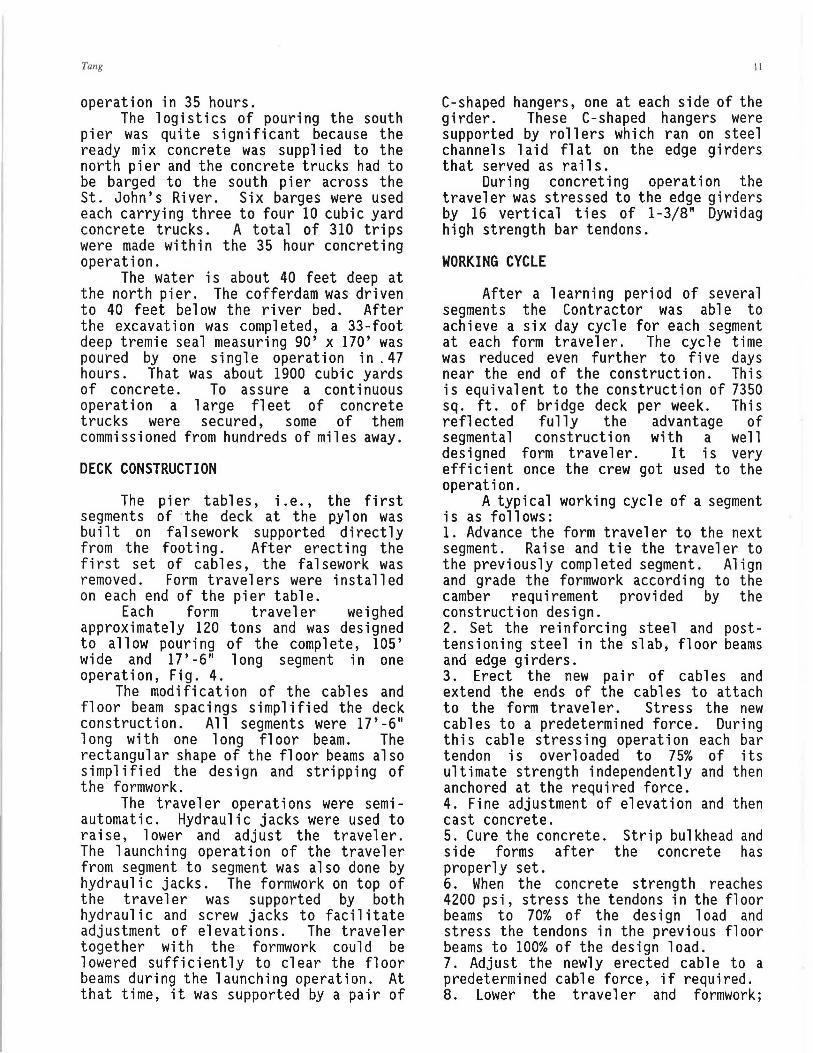
The total width of the deck is 105'-9", Fig. 3. It has two 8 feet wide solid edge girders. The depth of the edge girders varies from 5 feet at midspan to 6'-1" at the pylon. The original design ca 11 ed for precast concrete fl oar beams spaced at 11' -8" on center. The cable spacings were 35 feet on center along the edge girders. Thus, each panel of the deck has three floor beams.
CONSTRUCTION DESIGN
For a complex structure such as a cable-stayed bridge a significant amount of engineering is required for its actual construction.
In most bridges construction engineering consists of analyzing each construction stage based on the actual construction loading, checking of stresses and capacity of the structure, providing camber curves to the contractor to set up the formwork and possible adjustments . However, when construction
TRANSPORTATION RESEARCH RECORD 1290
is as complicated as in the Dame Point bridge, the construction engineering consultant has al so to develop a cab 1 e erection scheme, work out the pouring sequence of the segments, design the cable erection trusses and form traveler as well as the falsework and other temporary structures required for the pier table, center and end spans closure pours, among others.
The sequence of construction of certain elements is sometimes very important. By delaying construction of the bow tie strut between the tower legs, for example, cables could be erected easily. Such modifications of the construction sequence require very detailed analysis.
This deck configuration was modified in the final construction. Instead of the original double cables spaced at 35 feet, single cables at 17'-6" were used. The floor beam spacings were also changed from 11'-8" to 17'-6" thus making it equal to the cable spacing. This modification simplified the construction significantly. The precast floor beams were also changed to cast-in-place construction.
Modifications of the cable arrangement and floor beam configurations changed the structural system of the bridge. Extensive stress analysis was carried out to assure the safety of the structure under all possible loadings and that the modified structure met the intent of the original design.
To safeguard against possible future vibrations the cables were tied to each other by strands perpendicular to the cables. This was found to be very effective. No further vibrations have been observed since their installation.
FOUNDATIONS
Both end piers have pile footings and land piers. The Construction was quite conventional.
Construction of the two main piers, however, was more difficult. They stood on rather different foundations. At the south pi er the water is about 15 feet deep. 704 steel H-piles with 300-ton capacities were driven to 80 feet length. The seal measured 187' -3 11 x 94' x 14' deep. It was poured in one single
Tang
operation in 35 hours. The logistics of pouring the south
pi er was quite significant because the ready mix concrete was supplied to the north pier and the concrete trucks had to be barged to the south pi er across the St. John's River. Six barges were used each carrying three to four 10 cubic yard concrete trucks. A total of 310 trips were made within the 35 hour concreting operation.
The water is about 40 feet deep at the north pier. The cofferdam was driven to 40 feet be 1 ow the river bed. After the excavation was completed, a 33-foot deep tremie seal measuring 90' x 170' was poured by one single operation in .47 hours. That was about 1900 cubic yards of concrete. To assure a continuous operation a large fleet of concrete trucks were secured, some of them commissioned from hundreds of miles away.
DECK CONSTRUCTION
The pier tables, i.e., the first segments of ·the deck at the pylon was built on falsework supported directly from the footing. After erecting the first set of cables, the falsework was removed. Form travelers were installed on each end of the pier table.
Each form traveler weighed approximately 120 tons and was designed to allow pouring of the complete, 105' wide and 17'-6" long segment in one operation, Fig. 4.
The mod ifi cation of the cab 1 es and floor beam spacings simplified the deck construction. All segments were 17'-6" 1 ong with one 1 ong floor beam. The rectangular shape of the floor beams also simplified the design and stripping of the formwork.
The trave 1 er operations were semi -automatic. Hydraulic jacks were used to raise, lower and adjust the traveler. The launching operation of the traveler from segment to segment was also done by hydraulic jacks. The formwork on top of the traveler was supported by both hydraulic and screw jacks to facilitate adjustment of elevations. The traveler together with the formwork could be lowered sufficiently to clear the floor beams during the launching operation. At that time, it was supported by a pair of
11
C-shaped hangers, one at each side of the girder. These C-shaped hangers were supported by rollers which ran on steel channels laid flat on the edge girders that served as rails.
During concreting operation the traveler was stressed to the edge girders by 16 vert i ca 1 ti es of 1-3/8" Dywi dag high strength bar tendons.
WORKING CYCLE
After a 1 earning period of sever a 1 segments the Contractor was able to achieve a six day cycle for each segment at each form traveler. The cycle time was reduced even further to five days near the end of the construction. This is equivalent to the construction of 7350 sq. ft. of bridge deck per week. This reflected fully the advantage of segmental construction with a well designed form traveler. It is very efficient once the crew got used to the operation.
A typical working cycle of a segment is as follows: 1. Advance the form traveler to the next segment. Raise and tie the travel er to the previously completed segment. Align and grade the formwork according to the camber requirement provided by the construction design. 2. Set the reinforcing steel and posttens i oni ng steel in the slab, floor beams and edge girders. 3. Erect the new pair of cables and extend the ends of the cables to attach to the form traveler. Stress the new cables to a predetermined force. During this cable stressing operation each bar tendon is overloaded to 75% of its ultimate strength independently and then anchored at the required force. 4. Fine adjustment of elevation and then cast concrete. 5. Cure the concrete. Strip bulkhead and side forms after the concrete has properly set. 6. When the concrete strength reaches 4200 psi, stress the tendons in the floor beams to 70% of the design load and stress the tendons in the previous floor beams to 100% of the design load. 7. Adjust the newly erected cable to a predetermined cable force, if required. 8. Lower the traveler and formwork;
12
prepare for advancement to the next segment.
Cables were assembled on the deck at the same time as other work for the segment in the form travel er were progressing. Assemblage of the cables was, therefore, not at the critical path of construction.
A total of four form travelers were used simultaneously.
CABLES
This is the second major cablestayed bridge that used large diameter high strength bars as cable tendons. The first one was the Penang Bridge in Malaysia completed in 1985.
Quality control of the bar cables was very stringent. The 1-1/4 11 high strength bars with 150 ksi ultimate strength were delivered to the site at 40-foot lengths. They were then coupled together using specially designed couplers which met strict fatigue and ultimate load requirements. The cable anchorages and the couplers were tested in the University of Munich to assure that they met the required specifications.
The cables were fi 11 ed with cement grout after final adjustments. The bars and the steel pipe acted in composite action. The stee 1 pipes were welded together by full penetration welds. The fatigue criteria requires all these welds pass the x-ray tests before a cable could be erected. After the tot a 1 1 ength of the steel pipe had been completed the bar tendons were coupled together at one end of the pipe as they were pulled into the steel pipe.
The assembled cables, steel pipes and bar tendons together, were hoisted and erected by means of cranes. For the longest- cable, up to 728' long, three cranes were used to work in a synchronized fashion. Large spreader beams, Fig. 5, were used to reduce local bending moments of the steel pipes during erection until the cables attained sufficient tension to carry their own weight.
After the cranes picked up the cable, they first shifted the upper end of the cable into the tower. Then the lower end was placed in the edge girder
TRANSPORTATION RESEARCH RECORD 1290
form. It is significant to note that the erection of each cable, from the time the cranes picked up the steel pipe from the deck to the completion of the initial stressing, lasted only about 2 hours. Because reinforcing steel in the segment was being placed at the same time, the cable erection operation was practically outside of the critical path of the construction schedule.
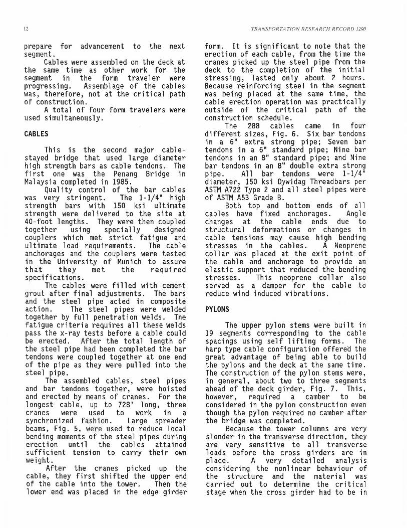
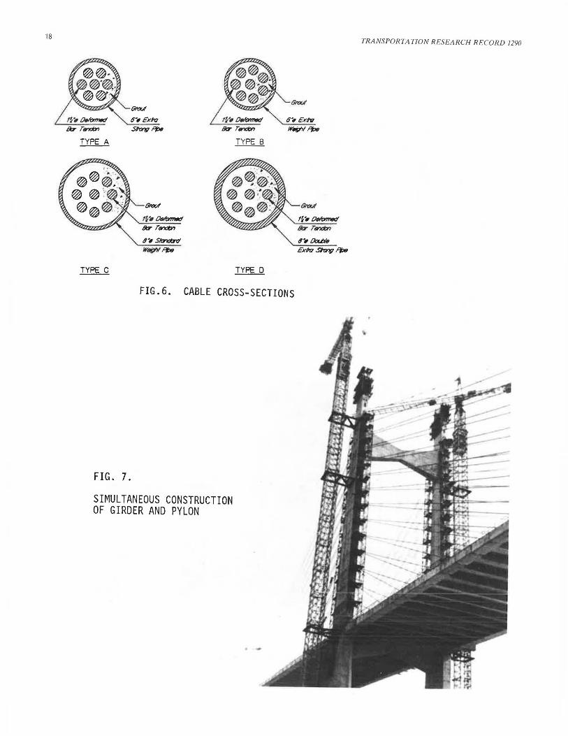
The 288 cables came in four different sizes, Fig. 6. Six bar tendons in a 611 extra strong pipe; Seven bar tendons in a 611 standard pipe; Nine bar tendons in an 811 standard pipe; and Nine bar tendons in an 811 double extra strong pipe. All bar tendons were 1-1/4 11
diameter, 150 ksi Dywidag Threadbars per ASTM A722 Type 2 and all steel pipes were of ASTM A53 Grade B.
Both top and bottom ends of all cables have fixed anchorages. Angle changes at the cable ends due to structural deformations or changes in cable tensions may cause high bending stresses in the cables. A Neoprene collar was placed at the exit point of the cable and anchorage to provide an elastic support that reduced the bending stresses. This neoprene collar also served as a damper for the cable to reduce wind induced vibrations.
PYLONS
The upper pylon stems were built in 19 segments corresponding to the cable spacings using self lifting forms. The harp type cable configuration offerea the great advantage of being able to build the pylons and the deck at the same time. The construction of the pylon stems were, in general, about two to three segments ahead of the deck girder, Fig. 7. This, however, required a camber to be considered in the pylon construction even though the pylon required no camber after the bridge was completed.
Because the tower columns are very slender in the transverse direction, they are very sensitive to all transverse loads before the cross girders are in place. A very detailed analysis considering the nonlinear behaviour of the structure and the material was carried out to determine the critical stage when the cross girder had to be in
Tang
p 1 ace before further construction could proceed.
The most critical loading was from hurricane wind. But a hurricane can usually be forecast ahead of its arrival. To secure the stability of the towers a special cable bracing system was designed, fabricated and stored at the site. This bracing system could be installed within hours after a hurricane was forecast for the vicinity. However, this bracing system was never used because the critical construction stages were not in the hurricane season.
END SPAN CLOSURE
The end diaphragm located on top of the end pier was constructed well before the closure to receive the precast girders from the approach span. It was tied down to the cap of the end pier by temporary prestressing ties and blackings.
The traveler was attached to the diaphragm before the closure was poured. This connection was designed to resist all possible vertical and horizontal forces due to temperature and incidental loadings. The ties and blackings between the diaphragm and the pier cap were then released. The closure was poured using a spec i a 1 1oca1 formwork supported by the traveler.
MID SPAN CLOSURE
A hinge connects the two halves of the bridge girder at the midspan. A box-type fl oar beam at the end of each cant i1 ever provides increased stiffness to the deck and the edge girders at this discontinuity points. Torsional rigidity of the box beam is further enhanced by connecting it with the adjacent floor beam by short longitudinal ribs.
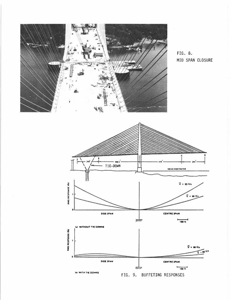
This midspan closure was poured under a symmetrical loading condition. The form traveler at the north cantilever was removed. The remaining traveler was placed at such a location that its load was evenly distributed to both cantilevers, Fig. 8. The actual load distribution was verified by lift-off readings of the vertical tie-downs which were the only attachments the form travelers had with the girders. Although
13
such an operation was not a requirement, it did simplify the analysis.
The hinge is a steel tongue and groove assembly. It is fixed to the girders by high tensile prestressing bars.
DECK PRESTRESSING
All floor beams have two tendons with 15 to 19 - 0.6 11 strands each. Because the edge girders are very stiff, the newly poured floor beams were stressed and reduced the prestressing force in the previously poured floor beams. This effect was compensated by a two-stage prestressing of the floor beam tendons.
The tendons in the newly completed floor beams were first stressed to 70% of their required force. These tendons were restressed to 100% of the required force after the succeeding floor beams were stressed. This not only reduced the effect from stressing the succeeding floor beams but also eliminated part of the losses due to creep and shrinkage of the concrete.
Longitudinal tendons were provided at the center portion and at both ends of the girders where axial compression from the horizontal components of the cable forces were small. They were stressed after the deck construction was completed.
AERODYNAMIC STABILITY DURING CONSTRUCTION
It is well known that cable-stayed bridges are more vulnerable to aerodynamic vibrations during construction stages than in completed stages. Extensive investigations were carried out for all critical construction stages of the Dame Point bridge before the final construction scheme was fully developed. A wind tunnel test was performed at the Low Speed Laboratory of the National Research Council in Ottawa, Canada. However, only a sectional model was used. Prior experience on other bridges showed that results from sectional models matches reasonably well with results of full model testings.
Investigations showed that the bridge built by cantilever method without any auxiliary supports or tie-downs was stable against vortex induced vibrations
14
-flexural, torsional and flutter vibrations. However, buffeting would cause significant overstresses in the structure at wind speeds at or over 80 mph. Buffeting might create significant vertical wind load on the bridge deck thus causing extremely high bending moments at the tower, Fig. 9.
The effect of buffeting can be reduced by increasing the natural frequency of the structure. This can be simply achieved by means of vertical or inclined tie-down cables connecting the bridge deck to a foundation. In the Dame Point bridge, at the most critical construction stage immediately before connecting the end cantilever to the end pier, the tie-down at the back span increased the natural frequency of the structure from 0.13 Hz to 0.22 Hz. This was sufficient to reduce the vertical , single peak amplitude at the tip of the main span cantilever from 10 feet to less than 4 feet. Comparing the weight of one 17'-6" segment will produce about 3 feet deflection at the end of the cantilever at this stage, a 4 feet oscillation under a hurricane wind was considered acceptable.
A tie-down system was designed and the required tension piles were driven and capped by a concrete foundation. The ties consisted of 2xl9-0.6" prestressing strands each . These strands could be installed easily and stressed by regular prestressing jacks. However, this tiedown system, although ready and stored at the jobsite was never used because, as mentioned before, all critical construction stages were outside of the hurricane season.
An opportunity to measure the flexural vertical vibration in the field was provided when the bridge was being prepared for the side span closure pour. Because the end of the cant i 1 ever was very close to the end pier, it was easy to record the re 1 at i ve movement between the cantilever and the pier cap under a gentle cross wind. The frequency was found to coincide with the calculated first mode frequency of 0 .13 Hz. ·The amplitude, as predicted, was small.
No noticeable vibrations of the cables were observed except in one or two incidents. Some long cables vibrated at a relatively low wind speed on a rainy
TRANSPORTATION RESEARCH RECORD 1290
day. Unfortunately, wind speed and amplitude were not recorded.
CAMBER CONTROL AND CABLE ADJUSTMENTS
The bridge deck of the Dame Point bridge is of a flexible type. For this type of bridge the most important geometry control is to assure that the local alignment is as close to the theoretical camber shape as possible. Global deviations can be corrected easily by cable adjustments. Any time during construction or after the bridge is completed, deflections as large as 2 to 3 feet can be corrected with relatively small changes in cable forces.
The analysis was based on linear theory except that the cable stiffness was adjusted according to the cable tension. A detailed nonlinear analysis, taking into consideration all displacements and variations in material stiffness was carried out for two construction cycles. Comparison of the results of the linear and nonlinear analysis showed that the nonlinear effects were negligible for the loading magnitude and sequence of the construction scheme.
Creep and shrinkage effects were calculated according to the CEB-FIP Model Code.
Camber curves for every construction stage were prepared before the start of construction. Comparison between the asbuilt curves and the theoretical curves was a regular control procedure for the elevations.
Modifications of the theoretical camber curves are sometimes necessary during the course of construction. Constant communication between the construction site and the design office is a prerequisite for a successful construction of such structures.
The maximum deviation of the bridge deck from the theoretically calculated camber curve at the time of the closure of the midspan hinge is less than three inches. Considering the span is 1300 feet long, this deviation is insignificant.
The cables were grouted after all permanent loads were in place.
Tang
CONSTRUCTION SCHEDULE
The bridge was tendered in November 1984. Notice to proceed for construction was given in March 1985. The contract stipulates a construction period of 36 months. Difficulties were encountered during pile driving for the south main pier. Additional load tests were carried out before final production piles were driven contributing to some delays. Other parts of the construction were slightly ahead of the schedule. The bridge was completed in September 1988.
ACKNOWLEDGMENT
The successful construction of the Dame Point Bridge is a result of a close cooperation between the Owner, the Contractor and the Engineers.
The Owner of the Dame Point Bridge is Jacksonville Transportation Authority {JTA). General Manager for the Owner is Sverdrup & Parcel.
15
The bridge was designed by Gerry Fox, Herbert Gl obig and Ray McCabe of Howard Needles Tammen & Bergendoff (HNTB).
Representing Jacksonville Transportation Authority to supervise and inspect construction was Leonard P. Drui an of Sverdrup & Walter Sharko of HNTB.
William Praderio was project manager for the Contractor, a joint venture of Pensacola-Tyger. Manfred Spannri ng of Dywidag Systems International was their technical adviser at the site.
Man-Chung Tang of DRC Consultants, Inc., collaborating with Khaled Shawwaf of OSI, was the project manager for all construction engineering work.
DRC engineers Jee-Bong Louie provided design modifications, Nien-Sheng Chung construction stage design, Hannskarl Bandel and Boris Levi ntov the form traveler and other equipment designs.
26 00' Main River Bridge
FIG. 1. ELEVATION OF THE DAME PO~NT BRIDGE
FIG 2. THE DAME POINT BRIDGE
....... .... ' .. ... · .......... . . . .. . .. ·,:·~ :;:::
.: . . :-::..: ::
105'-9"
FIG. 3.
DECK CROSS-SECTlON +-t l 1-6 11

FIG 4. FORM TRAVELER
FIG. 5. SPREADER BEAM FOR CABLE ERECTION
18
6-, £xm 6'1 E'xhl S~l')!:td W.Y,ll')!:td
TYPE A TYPE B
4-, Skrl«zrj 4'll a:ut's
Wst;N fJw £xm Sirng fJw
TYPE C TYPE D
FIG.6. CABLE CROSS-SECTIONS
FIG. 7.
SIMULTANEOUS CONSTRUCTION OF GIRDER AND PYLON
TRANSPORTATION RESEARCH RECORD 1290
... "' z 0 .. "' ... 0:
i 0:
~ .. .. z g .. IE .. :I IE
TIE-DOWN
SIOE S'AN
l•I WITHOUT Tll DOWNS
I
Q
SIOI $,AN
lbl WITH TIE DOWNS
FIG. 8.
MID SPAN CLOSURE
CINTllE !'AN
.,,,. , 1----1 100h
CINTIU S'AN
,.,, 'l'ooT."4 FIG. 9. BUFFETING RESPONSES