type 1290 vapor recovery regulator...w7427 type 1290 vapor recovery regulator figure 1. type 1290...
TRANSCRIPT
W7427
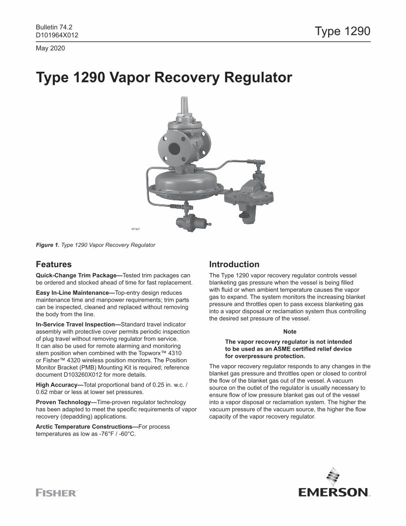
Type 1290 Vapor Recovery Regulator
Figure 1. Type 1290 Vapor Recovery Regulator
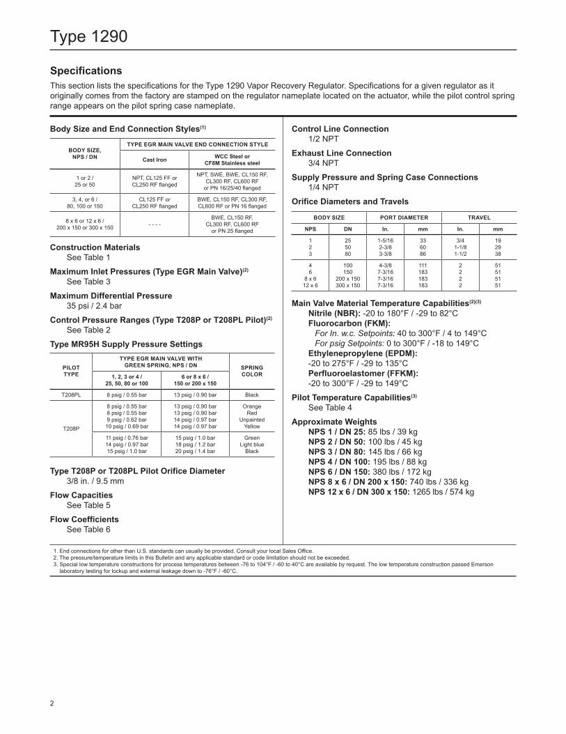
FeaturesQuick-Change Trim Package—Tested trim packages can be ordered and stocked ahead of time for fast replacement.Easy In-Line Maintenance—Top-entry design reduces maintenance time and manpower requirements; trim parts can be inspected, cleaned and replaced without removing the body from the line.In-Service Travel Inspection—Standard travel indicator assembly with protective cover permits periodic inspection of plug travel without removing regulator from service. It can also be used for remote alarming and monitoring stem position when combined with the Topworx™ 4310 or Fisher™ 4320 wireless position monitors. The Position Monitor Bracket (PMB) Mounting Kit is required; reference document D103260X012 for more details.High Accuracy—Total proportional band of 0.25 in. w.c. / 0.62 mbar or less at lower set pressures.Proven Technology—Time-proven regulator technology has been adapted to meet the specific requirements of vapor recovery (depadding) applications.Arctic Temperature Constructions—For process temperatures as low as -76°F / -60°C.
IntroductionThe Type 1290 vapor recovery regulator controls vessel blanketing gas pressure when the vessel is being filled with fluid or when ambient temperature causes the vapor gas to expand. The system monitors the increasing blanket pressure and throttles open to pass excess blanketing gas into a vapor disposal or reclamation system thus controlling the desired set pressure of the vessel.
NoteThe vapor recovery regulator is not intended to be used as an ASME certified relief device for overpressure protection.
The vapor recovery regulator responds to any changes in the blanket gas pressure and throttles open or closed to control the flow of the blanket gas out of the vessel. A vacuum source on the outlet of the regulator is usually necessary to ensure flow of low pressure blanket gas out of the vessel into a vapor disposal or reclamation system. The higher the vacuum pressure of the vacuum source, the higher the flow capacity of the vapor recovery regulator.
Bulletin 74.2D101964X012
May 2020
Type 1290
SpecificationsThis section lists the specifications for the Type 1290 Vapor Recovery Regulator. Specifications for a given regulator as it originally comes from the factory are stamped on the regulator nameplate located on the actuator, while the pilot control spring range appears on the pilot spring case nameplate.
Body Size and End Connection Styles(1)
Construction MaterialsSee Table 1
Maximum Inlet Pressures (Type EGR Main Valve)(2)
See Table 3Maximum Differential Pressure
35 psi / 2.4 barControl Pressure Ranges (Type T208P or T208PL Pilot)(2)
See Table 2Type MR95H Supply Pressure Settings
Type T208P or T208PL Pilot Orifice Diameter3/8 in. / 9.5 mm
Flow CapacitiesSee Table 5
Flow CoefficientsSee Table 6
Control Line Connection 1/2 NPT
Exhaust Line Connection3/4 NPT
Supply Pressure and Spring Case Connections1/4 NPT
Orifice Diameters and Travels
Main Valve Material Temperature Capabilities(2)(3)
Nitrile (NBR): -20 to 180°F / -29 to 82°CFluorocarbon (FKM):
For In. w.c. Setpoints: 40 to 300°F / 4 to 149°CFor psig Setpoints: 0 to 300°F / -18 to 149°C
Ethylenepropylene (EPDM): -20 to 275°F / -29 to 135°CPerfluoroelastomer (FFKM): -20 to 300°F / -29 to 149°C
Pilot Temperature Capabilities(3)
See Table 4Approximate Weights
NPS 1 / DN 25: 85 lbs / 39 kgNPS 2 / DN 50: 100 lbs / 45 kgNPS 3 / DN 80: 145 lbs / 66 kgNPS 4 / DN 100: 195 lbs / 88 kgNPS 6 / DN 150: 380 lbs / 172 kgNPS 8 x 6 / DN 200 x 150: 740 lbs / 336 kgNPS 12 x 6 / DN 300 x 150: 1265 lbs / 574 kg
BODY SIZE, NPS / DN
TYPE EGR MAIN VALVE END CONNECTION STYLE
Cast Iron WCC Steel or CF8M Stainless steel
1 or 2 /25 or 50
NPT, CL125 FF or CL250 RF flanged
NPT, SWE, BWE, CL150 RF, CL300 RF, CL600 RF
or PN 16/25/40 flanged
3, 4, or 6 / 80, 100 or 150
CL125 FF or CL250 RF flanged
BWE, CL150 RF, CL300 RF, CL600 RF or PN 16 flanged
8 x 6 or 12 x 6 / 200 x 150 or 300 x 150 - - - -
BWE, CL150 RF, CL300 RF, CL600 RF
or PN 25 flanged
PILOT TYPE
TYPE EGR MAIN VALVE WITH GREEN SPRING, NPS / DN SPRING
COLOR1, 2, 3 or 4 / 25, 50, 80 or 100
6 or 8 x 6 / 150 or 200 x 150
T208PL 8 psig / 0.55 bar 13 psig / 0.90 bar Black
T208P
8 psig / 0.55 bar8 psig / 0.55 bar9 psig / 0.62 bar10 psig / 0.69 bar
13 psig / 0.90 bar13 psig / 0.90 bar14 psig / 0.97 bar14 psig / 0.97 bar
OrangeRed
UnpaintedYellow
11 psig / 0.76 bar14 psig / 0.97 bar15 psig / 1.0 bar
15 psig / 1.0 bar18 psig / 1.2 bar20 psig / 1.4 bar
GreenLight blue
Black
BODY SIZE PORT DIAMETER TRAVEL
NPS DN In. mm In. mm
12 3
255080
1-5/162-3/83-3/8
336086
3/41-1/81-1/2
192938
46
8 x 612 x 6
100150
200 x 150300 x 150
4-3/87-3/167-3/167-3/16
111183183183
2222
51515151
1. End connections for other than U.S. standards can usually be provided. Consult your local Sales Office.2. The pressure/temperature limits in this Bulletin and any applicable standard or code limitation should not be exceeded.3. Special low temperature constructions for process temperatures between -76 to 104°F / -60 to 40°C are available by request. The low temperature construction passed Emerson
laboratory testing for lockup and external leakage down to -76°F / -60°C.
2
Type 1290
ATMOSPHERIC PRESSUREINTERMEDIATE PRESSURE
VACUUM PRESSURE
TANK PRESSURELOADING PRESSURE
E0063_07/08
ATMOSPHERIC PRESSURE
INTERMEDIATE PRESSUREVACUUM PRESSURETANK PRESSURE
LOADING PRESSURE
TYPE EGR MAIN VALVE
VAPOR RECOVERY VACUUM SOURCE
CONTROL LINE
TYPE T208P PILOT
SETPOINT ADJUSTMENT
EXHAUST LINE
VAPOR PRESSURE
TANK TYPE MR95H SUPPLY REGULATOR
FIXED RESTRICTION
TYPE 1098 ACTUATOR
ATMOSPHERIC PRESSURELOADING PRESSUREINTERMEDIATE PRESSUREVACUUM PRESSURETANK PRESSURE
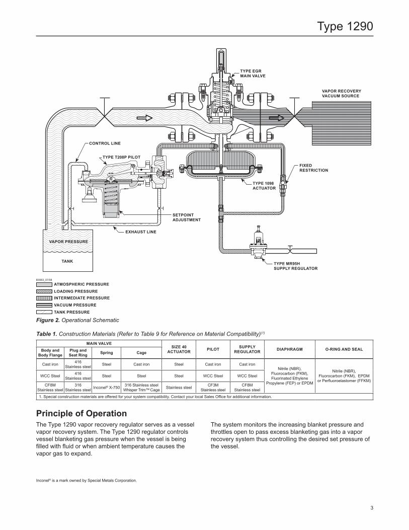
Figure 2. Operational Schematic
Table 1. Construction Materials (Refer to Table 9 for Reference on Material Compatibility)(1)
MAIN VALVESIZE 40
ACTUATOR PILOT SUPPLY REGULATOR DIAPHRAGM O-RING AND SEALBody and
Body FlangePlug and Seat Ring Spring Cage
Cast iron 416 Stainless steel Steel Cast iron Steel Cast iron Cast iron
Nitrile (NBR), Fluorocarbon (FKM), Fluorinated Ethylene
Propylene (FEP) or EPDM
Nitrile (NBR), Fluorocarbon (FKM), EPDM
or Perfluoroelastomer (FFKM)WCC Steel 416
Stainless steel Steel Steel Steel WCC Steel WCC Steel
CF8M Stainless steel
316 Stainless steel Inconel® X-750 316 Stainless steel
Whisper Trim™ Cage Stainless steel CF3M Stainless steel
CF8M Stainless steel
1. Special construction materials are offered for your system compatibility. Contact your local Sales Office for additional information.
Principle of OperationThe Type 1290 vapor recovery regulator serves as a vessel vapor recovery system. The Type 1290 regulator controls vessel blanketing gas pressure when the vessel is being filled with fluid or when ambient temperature causes the vapor gas to expand.
The system monitors the increasing blanket pressure and throttles open to pass excess blanketing gas into a vapor recovery system thus controlling the desired set pressure of the vessel.
Inconel® is a mark owned by Special Metals Corporation.
3
Type 1290
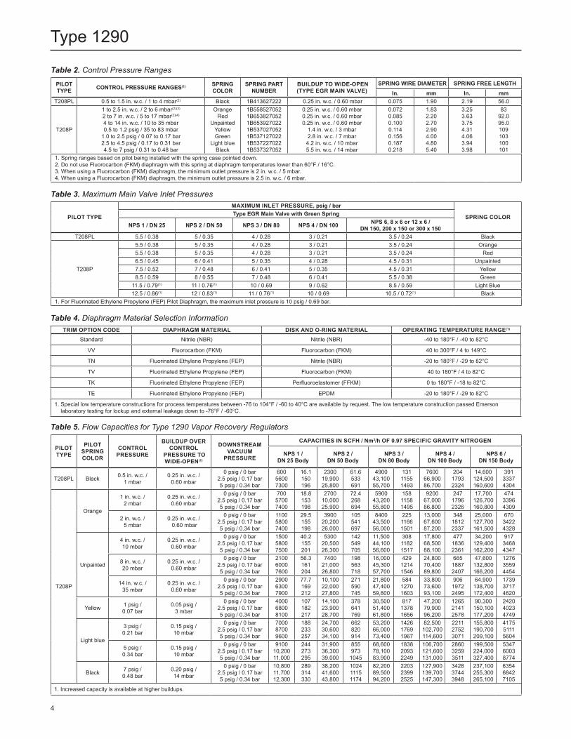
Table 2. Control Pressure Ranges
PILOT TYPE CONTROL PRESSURE RANGES(1) SPRING
COLORSPRING PART
NUMBER BUILDUP TO WIDE-OPEN (TYPE EGR MAIN VALVE)
SPRING WIRE DIAMETER SPRING FREE LENGTHIn. mm In. mm
T208PL 0.5 to 1.5 in. w.c. / 1 to 4 mbar(2) Black 1B413627222 0.25 in. w.c. / 0.60 mbar 0.075 1.90 2.19 56.0
T208P
1 to 2.5 in. w.c. / 2 to 6 mbar(2)(3)
2 to 7 in. w.c. / 5 to 17 mbar(2)(4)
4 to 14 in. w.c. / 10 to 35 mbar0.5 to 1.2 psig / 35 to 83 mbar
1.0 to 2.5 psig / 0.07 to 0.17 bar2.5 to 4.5 psig / 0.17 to 0.31 bar4.5 to 7 psig / 0.31 to 0.48 bar
OrangeRed
UnpaintedYellowGreen
Light blueBlack
1B5585270521B6538270521B6539270221B5370270521B5371270221B5372270221B537327052
0.25 in. w.c. / 0.60 mbar0.25 in. w.c. / 0.60 mbar0.25 in. w.c. / 0.60 mbar
1.4 in. w.c. / 3 mbar2.8 in. w.c. / 7 mbar4.2 in. w.c. / 10 mbar5.5 in. w.c. / 14 mbar
0.0720.0850.1000.1140.1560.1870.218
1.832.202.702.904.004.805.40
3.253.633.754.314.063.943.98
8392.095.0109103100101
1. Spring ranges based on pilot being installed with the spring case pointed down.2. Do not use Fluorocarbon (FKM) diaphragm with this spring at diaphragm temperatures lower than 60°F / 16°C.3. When using a Fluorocarbon (FKM) diaphragm, the minimum outlet pressure is 2 in. w.c. / 5 mbar.4. When using a Fluorocarbon (FKM) diaphragm, the minimum outlet pressure is 2.5 in. w.c. / 6 mbar.
Table 3. Maximum Main Valve Inlet Pressures
PILOT TYPE
MAXIMUM INLET PRESSURE, psig / bar
SPRING COLORType EGR Main Valve with Green Spring
NPS 1 / DN 25 NPS 2 / DN 50 NPS 3 / DN 80 NPS 4 / DN 100 NPS 6, 8 x 6 or 12 x 6 / DN 150, 200 x 150 or 300 x 150
T208PL 5.5 / 0.38 5 / 0.35 4 / 0.28 3 / 0.21 3.5 / 0.24 Black
T208P
5.5 / 0.38 5 / 0.35 4 / 0.28 3 / 0.21 3.5 / 0.24 Orange5.5 / 0.38 5 / 0.35 4 / 0.28 3 / 0.21 3.5 / 0.24 Red6.5 / 0.45 6 / 0.41 5 / 0.35 4 / 0.28 4.5 / 0.31 Unpainted7.5 / 0.52 7 / 0.48 6 / 0.41 5 / 0.35 4.5 / 0.31 Yellow8.5 / 0.59 8 / 0.55 7 / 0.48 6 / 0.41 5.5 / 0.38 Green
11.5 / 0.79(1) 11 / 0.76(1) 10 / 0.69 9 / 0.62 8.5 / 0.59 Light Blue12.5 / 0.86(1) 12 / 0.83(1) 11 / 0.76(1) 10 / 0.69 10.5 / 0.72(1) Black
1. For Fluorinated Ethylene Propylene (FEP) Pilot Diaphragm, the maximum inlet pressure is 10 psig / 0.69 bar.
Table 4. Diaphragm Material Selection InformationTRIM OPTION CODE DIAPHRAGM MATERIAL DISK AND O-RING MATERIAL OPERATING TEMPERATURE RANGE(1)
Standard Nitrile (NBR) Nitrile (NBR) -40 to 180°F / -40 to 82°C
VV Fluorocarbon (FKM) Fluorocarbon (FKM) 40 to 300°F / 4 to 149°C
TN Fluorinated Ethylene Propylene (FEP) Nitrile (NBR) -20 to 180°F / -29 to 82°C
TV Fluorinated Ethylene Propylene (FEP) Fluorocarbon (FKM) 40 to 180°F / 4 to 82°C
TK Fluorinated Ethylene Propylene (FEP) Perfluoroelastomer (FFKM) 0 to 180°F / -18 to 82°C
TE Fluorinated Ethylene Propylene (FEP) EPDM -20 to 180°F / -29 to 82°C
1. Special low temperature constructions for process temperatures between -76 to 104°F / -60 to 40°C are available by request. The low temperature construction passed Emerson laboratory testing for lockup and external leakage down to -76°F / -60°C.
Table 5. Flow Capacities for Type 1290 Vapor Recovery Regulators
PILOT TYPE
PILOT SPRING COLOR
CONTROL PRESSURE
BUILDUP OVER CONTROL
PRESSURE TO WIDE-OPEN(1)
DOWNSTREAM VACUUM
PRESSURE
CAPACITIES IN SCFH / Nm3/h OF 0.97 SPECIFIC GRAVITY NITROGEN
NPS 1 / DN 25 Body
NPS 2 / DN 50 Body
NPS 3 / DN 80 Body
NPS 4 / DN 100 Body
NPS 6 / DN 150 Body
T208PL Black 0.5 in. w.c. /1 mbar
0.25 in. w.c. /0.60 mbar
0 psig / 0 bar2.5 psig / 0.17 bar5 psig / 0.34 bar
60056007300
16.1150196
230019,90025,800
61.6533691
490043,10055,700
13111551493
760066,90086,700
20417932324
14,600124,500160,600
39133374304
T208P
Orange
1 in. w.c. /2 mbar
0.25 in. w.c. /0.60 mbar
0 psig / 0 bar2.5 psig / 0.17 bar5 psig / 0.34 bar
70057007400
18.8153198
270010,00025,900
72.4268694
590043,20055,800
15811581495
920067,00086,800
24717962326
17,700126,700160,800
47433964309
2 in. w.c. / 5 mbar
0.25 in. w.c. / 0.60 mbar
0 psig / 0 bar2.5 psig / 0.17 bar5 psig / 0.34 bar
110058007400
29.5155198
390020,20026,000
105541697
840043,50056,000
22511661501
13,00067,60087,200
34818122337
25,000127,700161,500
67034224328
Unpainted
4 in. w.c. / 10 mbar
0.25 in. w.c. /0.60 mbar
0 psig / 0 bar2.5 psig / 0.17 bar5 psig / 0.34 bar
150058007500
40.2155201
530020,50026,300
142549705
11,50044,10056,600
30811821517
17,80068,50088,100
47718362361
34,200129,400162,200
91734684347
8 in. w.c. / 20 mbar
0.25 in. w.c. /0.60 mbar
0 psig / 0 bar2.5 psig / 0.17 bar5 psig / 0.34 bar
210060007600
56.3161204
740021,00026,800
198563718
16,00045,30057,700
42912141546
24,80070,40089,800
66518872407
47,600132,800166,200
127635594454
14 in. w.c. / 35 mbar
0.25 in. w.c. /0.60 mbar
0 psig / 0 bar2.5 psig / 0.17 bar5 psig / 0.34 bar
290063007900
77.7169212
10,10022,00027,800
271590745
21,80047,40059,800
58412701603
33,80073,60093,100
90619722495
64,900138,700172,400
173937174620
Yellow 1 psig / 0.07 bar
0.05 psig /3 mbar
0 psig / 0 bar2.5 psig / 0.17 bar5 psig / 0.34 bar
400068008100
107182217
14,10023,90028,700
378641769
30,50051,40061,800
81713781656
47,20079,90096,200
126521412578
90,300150,100177,200
242040234749
Light blue
3 psig /0.21 bar
0.15 psig /10 mbar
0 psig / 0 bar2.5 psig / 0.17 bar5 psig / 0.34 bar
700087009600
188233257
24,70030,60034,100
662820914
53,20066,00073,400
142617691967
82,500102,700114,600
221127523071
155,800190,700209,100
417551115604
5 psig /0.34 bar
0.15 psig /10 mbar
0 psig / 0 bar2.5 psig / 0.17 bar5 psig / 0.34 bar
910010,20011,000
244273295
31,90036,30039,000
8559731045
68,60078,10083,900
183820932249
106,700121,600131,000
286032593511
199,500224,000327,400
534760038774
Black 7 psig /0.48 bar
0.20 psig /14 mbar
0 psig / 0 bar2.5 psig / 0.17 bar5 psig / 0.34 bar
10,80011,70012,300
289314330
38,20041,60043,800
102411151174
82,20089,50094,200
220323992525
127,900139,700147,300
342837443948
237,100255,300265,100
635468427105
1. Increased capacity is available at higher buildups.
4
Type 1290
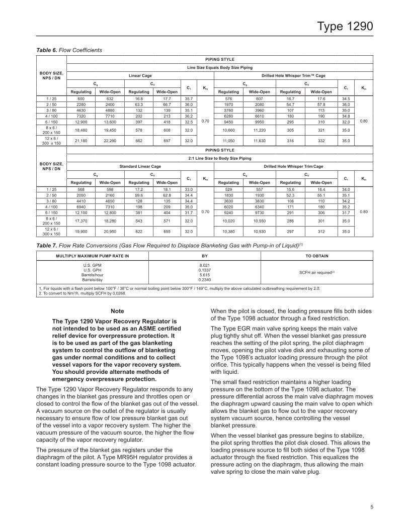
Table 6. Flow Coefficients
BODY SIZE, NPS / DN
PIPING STYLE
Line Size Equals Body Size Piping
Linear Cage Drilled Hole Whisper Trim™ Cage
Cg CVC1 Km
Cg CVC1 Km
Regulating Wide-Open Regulating Wide-Open Regulating Wide-Open Regulating Wide-Open1 / 25 600 632 16.8 17.7 35.7
0.70
576 607 16.7 17.6 34.5
0.80
2 / 50 2280 2400 63.3 66.7 36.0 1970 2080 54.7 57.8 36.03 / 80 4630 4880 132 139 35.1 3760 3960 107 113 35.04 / 100 7320 7710 202 213 36.2 6280 6610 180 190 34.86 / 150 12,900 13,600 397 418 32.5 9450 9950 295 310 32.08 x 6 /
200 x 150 18,480 19,450 578 608 32.0 10,660 11,220 305 321 35.0
12 x 6 / 300 x 150 21,180 22,290 662 697 32.0 11,050 11,630 316 332 35.0
BODY SIZE, NPS / DN
PIPING STYLE
2:1 Line Size to Body Size Piping
Standard Linear Cage Drilled Hole Whisper Trim Cage
Cg CVC1 Km
Cg CVC1 Km
Regulating Wide-Open Regulating Wide-Open Regulating Wide-Open Regulating Wide-Open1 / 25 568 598 17.2 18.1 33.0
0.70
529 557 15.6 16.4 34.0
0.80
2 / 50 2050 2160 59.6 62.8 34.4 1830 1930 52.3 55.1 35.13 / 80 4410 4650 128 135 34.4 3630 3830 106 110 34.24 / 100 6940 7310 198 209 35.0 6020 6340 171 180 35.26 / 150 12,100 12,800 381 404 31.7 9240 9730 291 306 31.78 x 6 /
200 x 150 17,370 18,280 543 571 32.0 10,020 10,550 286 301 35.0
12 x 6 / 300 x 150 19,900 20,950 622 655 32.0 10,380 10,930 297 312 35.0
MULTIPLY MAXIMUM PUMP RATE IN BY TO OBTAIN
U.S. GPMU.S. GPH
Barrels/hourBarrels/day
8.0210.13375.6150.2340
SCFH air required(2)
1. For liquids with a flash point below 100°F / 38°C or normal boiling point below 300°F / 149°C, multiply the above calculated outbreathing requirement by 2.0.2. To convert to Nm3/h, multiply SCFH by 0.0268.
Table 7. Flow Rate Conversions (Gas Flow Required to Displace Blanketing Gas with Pump-in of Liquid)(1)
NoteThe Type 1290 Vapor Recovery Regulator is not intended to be used as an ASME certified relief device for overpressure protection. It is to be used as part of the gas blanketing system to control the outflow of blanketing gas under normal conditions and to collect vessel vapors for the vapor recovery system. You should provide alternate methods of emergency overpressure protection.
The Type 1290 Vapor Recovery Regulator responds to any changes in the blanket gas pressure and throttles open or closed to control the flow of the blanket gas out of the vessel. A vacuum source on the outlet of the regulator is usually necessary to ensure flow of low pressure blanket gas out of the vessel into a vapor recovery system. The higher the vacuum pressure of the vacuum source, the higher the flow capacity of the vapor recovery regulator.The pressure of the blanket gas registers under the diaphragm of the pilot. A Type MR95H regulator provides a constant loading pressure source to the Type 1098 actuator.
When the pilot is closed, the loading pressure fills both sides of the Type 1098 actuator through a fixed restriction.The Type EGR main valve spring keeps the main valve plug tightly shut off. When the vessel blanket gas pressure reaches the setting of the pilot spring, the pilot diaphragm moves, opening the pilot valve disk and exhausting some of the Type 1098’s actuator loading pressure through the pilot orifice. This typically happens when the vessel is being filled with liquid.The small fixed restriction maintains a higher loading pressure on the bottom of the Type 1098 actuator. The pressure differential across the main valve diaphragm moves the diaphragm upward causing the main valve to open which allows the blanket gas to flow out to the vapor recovery system vacuum source, hence controlling the vessel blanket pressure. When the vessel blanket gas pressure begins to stabilize, the pilot spring throttles the pilot disk closed. This allows the loading pressure source to fill both sides of the Type 1098 actuator through the fixed restriction. This equalizes the pressure acting on the diaphragm, thus allowing the main valve spring to close the main valve plug.
5
Type 1290
CgP1Sin DegQ= 520 3417 ∆P GT C1 P1
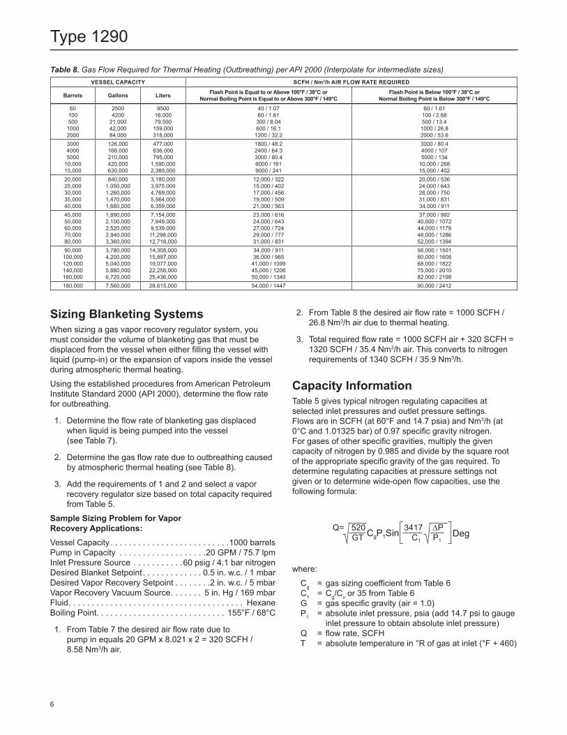
VESSEL CAPACITY SCFH / Nm3/h AIR FLOW RATE REQUIRED
Barrels Gallons Liters Flash Point is Equal to or Above 100°F / 38°C or Normal Boiling Point is Equal to or Above 300°F / 149°C
Flash Point is Below 100°F / 38°C or Normal Boiling Point is Below 300°F / 149°C
6010050010002000
25004200
21,00042,00084,000
950016,00079,500159,000318,000
40 / 1.0760 / 1.61300 / 8.04600 / 16.11200 / 32.2
60 / 1.61100 / 2.68500 / 13.41000 / 26.82000 / 53.6
300040005000
10,00015,000
126,000168,000210,000420,000630,000
477,000636,000795,000
1,590,0002,385,000
1800 / 48.22400 / 64.33000 / 80.46000 / 1619000 / 241
3000 / 80.44000 / 1075000 / 134
10,000 / 26815,000 / 402
20,00025,00030,00035,00040,000
840,0001,050,0001,260,0001,470,0001,680,000
3,180,0003,975,0004,769,0005,564,0006,359,000
12,000 / 32215,000 / 40217,000 / 45619,000 / 50921,000 / 563
20,000 / 53624,000 / 64328,000 / 75031,000 / 83134,000 / 911
45,00050,00060,00070,00080,000
1,890,0002,100,0002,520,0002,940,0003,360,000
7,154,0007,949,0009,539,00011,298,00012,718,000
23,000 / 61624,000 / 64327,000 / 72429,000 / 77731,000 / 831
37,000 / 99240,000 / 107244,000 / 117948,000 / 128652,000 / 1394
90,000100,000120,000140,000160,000
3,780,0004,200,0005,040,0005,880,0006,720,000
14,308,00015,897,00019,077,00022,256,00025,436,000
34,000 / 91136,000 / 96541,000 / 109945,000 / 120650,000 / 1340
56,000 / 150160,000 / 160868,000 / 182275,000 / 201082,000 / 2198
180,000 7,560,000 28,615,000 54,000 / 1447 90,000 / 2412
Table 8. Gas Flow Required for Thermal Heating (Outbreathing) per API 2000 (Interpolate for intermediate sizes)
Sizing Blanketing SystemsWhen sizing a gas vapor recovery regulator system, you must consider the volume of blanketing gas that must be displaced from the vessel when either filling the vessel with liquid (pump-in) or the expansion of vapors inside the vessel during atmospheric thermal heating.Using the established procedures from American Petroleum Institute Standard 2000 (API 2000), determine the flow rate for outbreathing.
1. Determine the flow rate of blanketing gas displaced when liquid is being pumped into the vessel (see Table 7).
2. Determine the gas flow rate due to outbreathing caused by atmospheric thermal heating (see Table 8).
3. Add the requirements of 1 and 2 and select a vapor recovery regulator size based on total capacity required from Table 5.
Sample Sizing Problem for Vapor Recovery Applications:Vessel Capacity . . . . . . . . . . . . . . . . . . . . . . . . . .1000 barrelsPump in Capacity . . . . . . . . . . . . . . . . . . .20 GPM / 75.7 lpmInlet Pressure Source . . . . . . . . . . .60 psig / 4.1 bar nitrogenDesired Blanket Setpoint . . . . . . . . . . . . . 0.5 in. w.c. / 1 mbarDesired Vapor Recovery Setpoint . . . . . . . .2 in. w.c. / 5 mbarVapor Recovery Vacuum Source . . . . . . . 5 in. Hg / 169 mbarFluid . . . . . . . . . . . . . . . . . . . . . . . . . . . . . . . . . . . . . . HexaneBoiling Point. . . . . . . . . . . . . . . . . . . . . . . . . . . . 155°F / 68°C
1. From Table 7 the desired air flow rate due to pump in equals 20 GPM x 8.021 x 2 = 320 SCFH / 8.58 Nm3/h air.
2. From Table 8 the desired air flow rate = 1000 SCFH / 26.8 Nm3/h air due to thermal heating.
3. Total required flow rate = 1000 SCFH air + 320 SCFH = 1320 SCFH / 35.4 Nm3/h air. This converts to nitrogen requirements of 1340 SCFH / 35.9 Nm3/h.
Capacity InformationTable 5 gives typical nitrogen regulating capacities at selected inlet pressures and outlet pressure settings. Flows are in SCFH (at 60°F and 14.7 psia) and Nm3/h (at 0°C and 1.01325 bar) of 0.97 specific gravity nitrogen. For gases of other specific gravities, multiply the given capacity of nitrogen by 0.985 and divide by the square root of the appropriate specific gravity of the gas required. To determine regulating capacities at pressure settings not given or to determine wide-open flow capacities, use the following formula:
where: Cg = gas sizing coefficient from Table 6 C1 = Cg/Cv or 35 from Table 6 G = gas specific gravity (air = 1.0) P1 = absolute inlet pressure, psia (add 14.7 psi to gauge
inlet pressure to obtain absolute inlet pressure) Q = flow rate, SCFH T = absolute temperature in °R of gas at inlet (°F + 460)
6
Type 1290
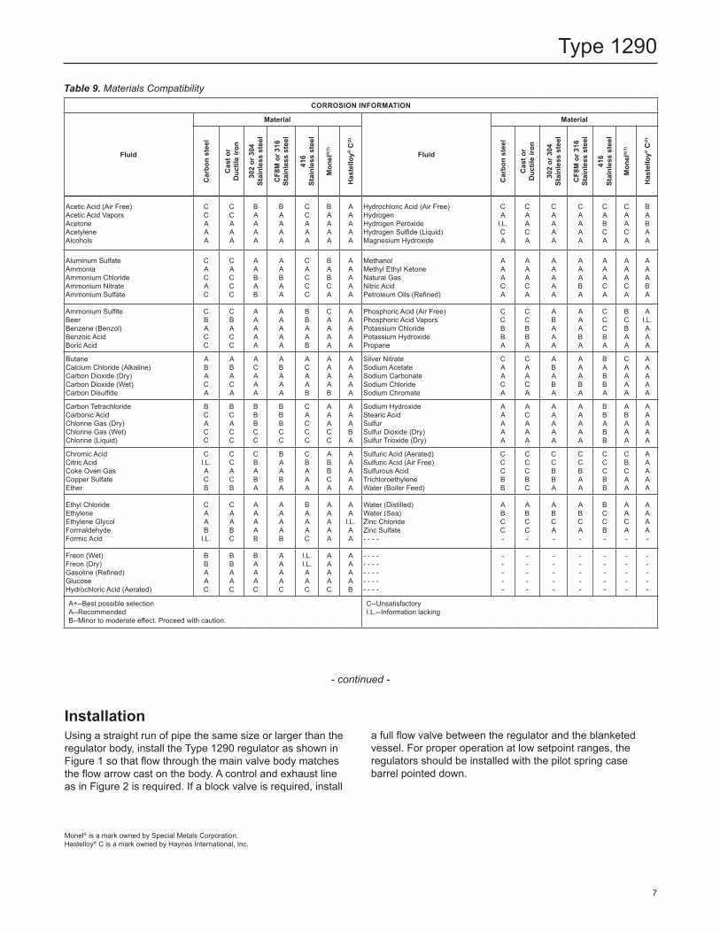
CORROSION INFORMATION
Fluid
Material
Fluid
Material
Car
bon
stee
l
Cas
t or
Duc
tile
iron
302
or 3
04
Stai
nles
s st
eel
CF8
M o
r 316
St
ainl
ess
stee
l
416
Stai
nles
s st
eel
Mon
el®
(1)
Has
tello
y® C
(2)
Car
bon
stee
l
Cas
t or
Duc
tile
iron
302
or 3
04
Stai
nles
s st
eel
CF8
M o
r 316
St
ainl
ess
stee
l
416
Stai
nles
s st
eel
Mon
el®
(1)
Has
tello
y® C
(2)
Acetic Acid (Air Free)Acetic Acid VaporsAcetoneAcetyleneAlcohols
CCAAA
CCAAA
BAAAA
BAAAA
CCAAA
BAAAA
AAAAA
Hydrochloric Acid (Air Free)HydrogenHydrogen PeroxideHydrogen Sulfide (Liquid)Magnesium Hydroxide
CA
I.L.CA
CAACA
CAAAA
CAAAA
CABCA
CAACA
BABAA
Aluminum SulfateAmmoniaAmmonium ChlorideAmmonium NitrateAmmonium Sulfate
CACAC
CACCC
AABAB
AABAA
CACCC
BABCA
AAAAA
MethanolMethyl Ethyl KetoneNatural GasNitric AcidPetroleum Oils (Refined)
AAACA
AAACA
AAAAA
AAABA
AAACA
AAACA
AAABA
Ammonium SulfiteBeerBenzene (Benzol)Benzoic AcidBoric Acid
CBACC
CBACC
AAAAA
AAAAA
BBAAB
CAAAA
AAAAA
Phosphoric Acid (Air Free)Phosphoric Acid VaporsPotassium ChloridePotassium HydroxidePropane
CCBBA
CCBBA
ABAAA
AAABA
CCCBA
BCBAA
AI.L.AAA
ButaneCalcium Chloride (Alkaline)Carbon Dioxide (Dry)Carbon Dioxide (Wet)Carbon Disulfide
ABACA
ABACA
ACAAA
ABAAA
ACAAB
AAAAB
AAAAA
Silver NitrateSodium AcetateSodium CarbonateSodium ChlorideSodium Chromate
CAACA
CAACA
ABABA
AAABA
BABBA
CAAAA
AAAAA
Carbon TetrachlorideCarbonic AcidChlorine Gas (Dry)Chlorine Gas (Wet)Chlorine (Liquid)
BCACC
BCACC
BBBCC
BBBCC
CACCC
AAACC
AAABA
Sodium HydroxideStearic AcidSulfurSulfur Dioxide (Dry)Sulfur Trioxide (Dry)
AAAAA
ACAAA
AAAAA
AAAAA
BBABB
ABAAA
AAAAA
Chromic AcidCitric AcidCoke Oven GasCopper SulfateEther
CI.L.ACB
CCACB
CBABA
BAABA
CBAAA
ABBCA
AAAAA
Sulfuric Acid (Aerated)Sulfuric Acid (Air Free)Sulfurous AcidTrichloroethyleneWater (Boiler Feed)
CCCBB
CCCBC
CCBBA
CCBAA
CCCBB
CBCAA
AAAAA
Ethyl ChlorideEthyleneEthylene GlycolFormaldehydeFormic Acid
CAAB
I.L.
CAABC
AAAAB
AAAAB
BAAAC
AAAAA
AA
I.L.AA
Water (Distilled)Water (Sea)Zinc ChlorideZinc Sulfate- - - -
ABCC-
ABCC-
ABCA-
ABCA-
BCCB-
AACA-
AAAA-
Freon (Wet)Freon (Dry)Gasoline (Refined)GlucoseHydrochloric Acid (Aerated)
BBAAC
BBAAC
BAAAC
AAAAC
I.L.I.L.AAC
AAAAC
AAAAB
- - - -- - - -- - - -- - - -- - - -
-----
-----
-----
-----
-----
-----
-----
A+--Best possible selectionA--RecommendedB--Minor to moderate effect. Proceed with caution.
C--UnsatisfactoryI.L.--Information lacking
Table 9. Materials Compatibility
- continued -
Installation Using a straight run of pipe the same size or larger than the regulator body, install the Type 1290 regulator as shown in Figure 1 so that flow through the main valve body matches the flow arrow cast on the body. A control and exhaust line as in Figure 2 is required. If a block valve is required, install
a full flow valve between the regulator and the blanketed vessel. For proper operation at low setpoint ranges, the regulators should be installed with the pilot spring case barrel pointed down.
Monel® is a mark owned by Special Metals Corporation.Hastelloy® C is a mark owned by Haynes International, Inc.
7
Type 1290
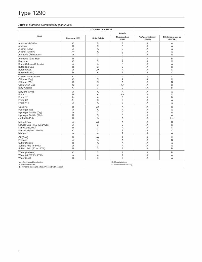
FLUID INFORMATION
FluidMaterial
Neoprene (CR) Nitrile (NBR) Fluorocarbon (FKM)
Perfluorelastomer (FFKM)
Ethylenepropylene (EPDM)
Acetic Acid (30%)AcetoneAlcohol (Ethyl)Alcohol (Methyl)Ammonia (Anhydrous)
CBA
A+A
BCAAC
BCBCC
AAAAA
AAAAA
Ammonia (Gas, Hot)BenzeneBrine (Calcium Chloride)Butadiene GasButane (Gas)Butane (Liquid)
BCABAB
CCACA+A
CABBAA
AAAAAA
BCACCC
Carbon TetrachlorideChlorine (Dry)Chlorine (Wet)Coke Oven GasEthyl Acetate
CCCCC
CCCBC
AAA
A+C
AAAAA
CCCCB
Ethylene GlycolFreon 11Freon 12Freon 22Freon 114
AB
A+A+A
AAACA
AA+BCB
AAAAA
ACBAA
GasolineHydrogen GasHydrogen Sulfide (Dry)Hydrogen Sulfide (Wet)Jet Fuel (JP-4)
BAABC
A+ACCA
AACCA
AAAAA
CAAA
I.L.
Natural GasNatural Gas + H2S (Sour Gas)Nitric Acid (20%)Nitric Acid (50 to 100%)Nitrogen
AABCA
A+BCCA
ACAAA
AAAAA
CCCCA
Oil (Fuel)PropaneSulfur DioxideSulfuric Acid (to 50%)Sulfuric Acid (50 to 100%)
BABAB
A+AACC
AAAAA
AAAAA
CCAAB
Water (Ambient)Water (at 200°F / 93°C)Water (Sea)
CAC
CAB
AAB
AAA
BAA
A+--Best possible selectionA--RecommendedB--Minor to moderate effect. Proceed with caution.
C--UnsatisfactoryI.L.--Information lacking
Table 9. Materials Compatibility (continued)
8
Type 1290
A/2
A
G
D
11.56 /294
16.06 / 408
13.12 /333 AR
Z
1/2 NPT CONTROL LINE CONNECTION
TYPE Y602-1VENT
TYPE T208P PILOT
EXHAUST LINE(3/4 NPT)
SUPPLY PRESSURE CONNECTION (1/4 NPT)
TYPE MR95H
1/4 NPT GAUGE TAP CONNECTION
TRIM REMOVAL CLEARANCE
ACTUATOR REMOVAL
CLEARANCE
IN. / mm
SIZE 40 ACTUATOR
B2442-1
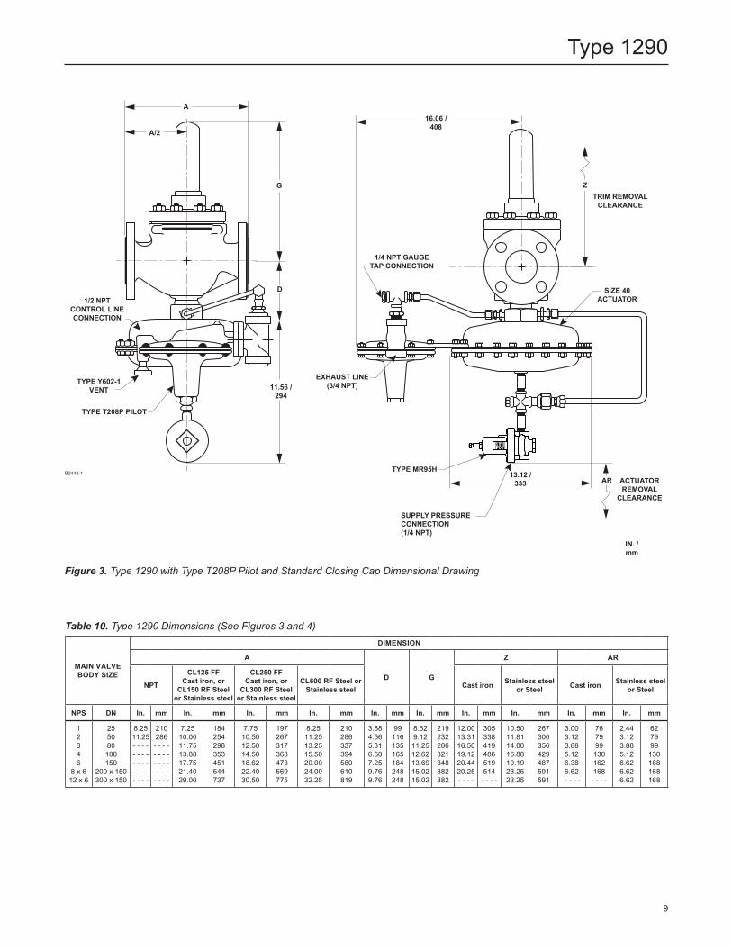
Figure 3. Type 1290 with Type T208P Pilot and Standard Closing Cap Dimensional Drawing
MAIN VALVE BODY SIZE
DIMENSION
A
D G
Z AR
NPT
CL125 FF Cast iron, or
CL150 RF Steel or Stainless steel
CL250 FF Cast iron, or
CL300 RF Steel or Stainless steel
CL600 RF Steel or Stainless steel Cast iron Stainless steel
or Steel Cast iron Stainless steel or Steel
NPS DN In. mm In. mm In. mm In. mm In. mm In. mm In. mm In. mm In. mm In. mm
1 2 3 4 6
8 x 612 x 6
255080100150
200 x 150300 x 150
8.25 11.25- - - -- - - -- - - -- - - -- - - -
210286- - - -- - - -- - - - - - - - - - - -
7.25 10.0011.7513.8817.7521.4029.00
184254298353451544737
7.7510.5012.5014.5018.6222.4030.50
197267317368473569775
8.2511.2513.2515.5020.0024.0032.25
210286337394580610819
3.884.565.316.507.259.769.76
99116135165184248248
8.629.12 11.25 12.6213.6915.0215.02
219232286321348382382
12.0013.3116.5019.1220.4420.25- - - -
305338419486519514- - - -
10.5011.8114.0016.8819.1923.2523.25
267300356429487591591
3.003.123.885.126.386.62 - - - -
767999130162168- - - -
2.443.123.885.126.626.626.62
627999
130168168168
Table 10. Type 1290 Dimensions (See Figures 3 and 4)
9
Type 1290
A/2A
G
D
11.56 /294
16.06 / 408
13.12 /333 AR
Z
1/2 NPT CONTROL LINE CONNECTION
TYPE Y602-1VENT
TYPE T208P PILOT
EXHAUST LINE
(3/4 NPT)
SUPPLY PRESSURE CONNECTION (1/4 NPT)
TYPE MR95H
1/4 NPT GAUGE TAP CONNECTION
TRIM REMOVAL CLEARANCE
ACTUATOR REMOVAL
CLEARANCE
IN. / mm
SIZE 40 ACTUATOR
Ordering GuideConstruction (Select One) Standard NACE
Type EGR Main ValveMain Valve Body Size (Select One) NPS 1 / DN 25*** NPS 2 / DN 50*** NPS 3 / DN 80*** NPS 4 / DN 100*** NPS 6 / DN 150** NPS 8 x 6 / DN 200 x 150* NPS 12 x 6 / DN 300 x 150*Main Valve Body Material (Select One) Cast iron*** WCC Steel*** CF8M Stainless steel (NACE)**
Type EGRMain Valve End Connection Style (Select One)Cast Iron Body NPT (NPS 1 and 2 / DN 25 and 50 only)*** CL125 FF*** CL250 RF***WCC Steel or CF8M Stainless steel Body NPT (NPS 1 and 2 / DN 25 and 50 only)*** SWE (NPS 1 and 2 / DN 25 and 50 only)* CL150 RF*** CL300 RF*** CL600 RF*** BWE 40** BWE 80* PN 16/25/40* __________ please specify rating
B2442-1
- continued -
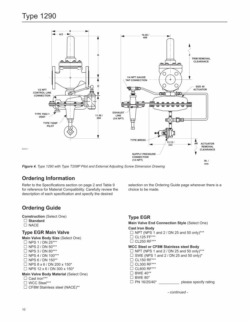
Ordering InformationRefer to the Specifications section on page 2 and Table 9 for reference for Material Compatibility. Carefully review the description of each specification and specify the desired
selection on the Ordering Guide page wherever there is a choice to be made.
Figure 4. Type 1290 with Type T208P Pilot and External Adjusting Screw Dimension Drawing
10
Type 1290
Type EGR (continued) Main Valve Body Flange Material (Select One) Cast iron*** WCC Steel*** CF8M Stainless steel (NACE)**Percent Travel or Travel Stop (Select One) 100 percent (standard)*** 70 percent (NPS 2 / DN 50 only)** 40 percent (Not available for NPS 1 and 2 /
DN 25 and 50)** 30 percent (NPS 2 / DN 50 only)**Main Valve Cage Type and Material (Select One) Linear, CF8M Stainless steel (NACE)*** Whisper Trim™ Cage, 416 Stainless steel Whisper Trim Cage, 316 Stainless steel (NACE) Quick Opening, Cast iron Quick Opening, Steel (for NPS 6 / DN 150 body only)Main Valve Spring Range (Select One) 60 psig / 4.1 bar maximum drop, Green**Main Valve Spring Steel*** Inconel® X-750 (NACE)(1)***O-ring and Seal Material (Select One) Nitrile (NBR)*** Fluorocarbon (FKM)** EPDM** Perflouroelastomer (FFKM)
Type 1098 ActuatorLower Diaphragm Case Material (Select One) Steel*** Stainless steel**Bonnet Material (Select One) Steel*** Stainless steel**O-ring Material (Select One) Nitrile (NBR)*** Fluorocarbon (FKM)** EPDM**Diaphragm Material (Select One) Nitrile (NBR)*** Fluorocarbon (FKM)** EPDM**
Type MR95H Supply Pressure RegulatorBody Material (Select One) Cast iron*** Steel*** Stainless steel***
Type MR95HSpring Case Material (Select One) Cast iron*** Steel*** Stainless steel***Valve Plug Material (Select One) 416 Stainless steel with Nitrile (NBR)*** 416 Stainless steel with Fluorocarbon (FKM)*** 316 Stainless steel with Neoprene (CR) (NACE)** 316 Stainless steel with Fluorocarbon (FKM)**Outlet Pressure Range (Select One) 15 to 30 psig / 1.0 to 2.1 bar, Yellow***Diaphragm Material (Select One) Neoprene (CR)*** Fluorocarbon (FKM)**
Type T208P or T208PL PilotBody, Spring Case Assembly and Diaphragm Casing Material (Select One) Cast iron WCC Steel CF3M Stainless steelControl Pressure Range (Select One)Type T208PL 0.5 to 1.5 in. w.c. / 1 to 4 mbar, Black***Type T208P 1.0 to 2.5 in. w.c. / 2 to 6 mbar, Orange*** 2 to 7 in. w.c. / 5 to 17 mbar, Red*** 4 to 14 in. w.c. / 10 to 35 mbar, Unpainted*** 0.5 to 1.2 psig / 35 to 83 mbar, Yellow*** 1 to 2.5 psig / 0.07 to 0.17 bar, Green*** 2.5 to 4.5 psig / 0.17 to 0.31 bar, Light Blue*** 4.5 to 7 psig / 0.31 to 0.48 bar, Black***Diaphragm Material (Select One) Nitrile (NBR)*** Fluorocarbon (FKM)** Fluorinated Ethylene Propylene (FEP)O-ring and Seal Material (Select One) Nitrile (NBR)*** Fluorocarbon (FKM)** EPDM** Perfluoroelastomer (FFKM)*Closing Cap Material (Select One)Type T208PL ZincType T208P Plastic*** Steel** Stainless steel**Vent Assembly (Select One) Spring Case Up (Type Y602-11)*** Spring Case Down (Type Y602-1)***
Inconel® is a mark owned by Special Metals Corporation.
Ordering Guide (continued)
- continued -
11
Type 1290
Regulators Quick Order Guide* * * Readily Available for Shipment
* * Allow Additional Time for Shipment
* Special Order, Constructed from Non-Stocked Parts. Consult your local Sales Office for Availability.
Availability of the product being ordered is determined by the component with the longest shipping time for the requested construction.
Specification WorksheetApplication Specifications:Tank Size ____________________________________Pump In Rate _________________________________Pump Out Rate _______________________________Blanketing Gas (Type and Specific Gravity) _________Pressure Requirements (Please Designate Units):Maximum Inlet Pressure (P1max) ___________________Minimum Inlet Pressure (P1min) ___________________Control Pressure Setting (P2) ____________________Maximum Flow (Qmax) __________________________Accuracy Requirements: 0.25 in. w.c. / 0.60 mbar 0.5 in. w.c. / 1 mbar 1 in. w.c. / 2 mbar 2 in. w.c. / 5 mbar Other ____________________________________Other Specifications:Is a vapor recovery regulator required? Yes No Special Material Requirements: Ductile iron Steel Stainless steel Hastelloy® C Other _________Other Requirements: ______________________________________________________________________
Ordering Guide (continued)
Parts KitsReplacement Parts Kit (Optional) Yes, send one replacement parts kit to match this order
for each unit.Quick-Change Trim Package (Optional) Yes, send one main valve Quick-Change Trim Package
to match this order.Wireless Position Monitor Mounting Kit (Optional) Yes, send one mounting kit for mounting the
Topworx™ 4310 or the Fisher™ 4320 wireless position monitor.
Hastelloy® C is a mark owned by Haynes International, Inc.
D101964X012 © 1994, 2020 Emerson Process Management Regulator Technologies, Inc. All rights reserved. 05/20. The Emerson logo is a trademark and service mark of Emerson Electric Co. All other marks are the property of their prospective owners. Fisher™ is a mark owned by Fisher Controls International LLC, a business of Emerson Automation Solutions.
The contents of this publication are presented for informational purposes only, and while every effort has been made to ensure their accuracy, they are not to be construed as warranties or guarantees, express or implied, regarding the products or services described herein or their use or applicability. All sales are governed by our terms and conditions, which are available upon request. We reserve the right to modify or improve the designs or specifications of such products at any time without notice.
Emerson Process Management Regulator Technologies, Inc does not assume responsibility for the selection, use or maintenance of any product. Responsibility for proper selection, use and maintenance of any Emerson Process Management Regulator Technologies, Inc. product remains solely with the purchaser.
Type 1290
Facebook.com/EmersonAutomationSolutions
LinkedIn.com/company/emerson-automation-solutions
Twitter.com/emr_automation
Fisher.com
Emerson Automation Solutions
Americas McKinney, Texas 75070 USA T +1 800 558 5853
+1 972 548 3574
Europe Bologna 40013, Italy T +39 051 419 0611
Asia Pacific Singapore 128461, Singapore T +65 6777 8211
Middle East and Africa Dubai, United Arab Emirates T +971 4 811 8100