unesco solar panel
TRANSCRIPT


Renewable Energies series
title.qxd 11/20/03 12:03 PM Page i

UNESCO TOOLKIT OF LEARNING AND TEACHING MATERIALS
Solar Photovoltaic SystemsTechnical Training Manual
Herbert A. Wade
Illustrated by
Gloria McConnaghy
UNESCO PUBLISHING
title.qxd 11/20/03 12:03 PM Page iii

In the same series:
Geothermal energySolar detoxificationSolar photovoltaic project development
The designations employed and the presentation of material throughout this
publication do not imply the expression of any opinion whatsoever on the part of
UNESCO concerning the legal status of any country, territory, city or area or of its
authorities, or concerning the delimitation of its frontiers or boundaries.
The author is responsible for the choice and the presentation of the facts
contained in this book and for the opinions expressed therein, which are not
necessarily those of UNESCO and do not commit the Organization.
Published in 2003 by the United Nations Educational,
Scientific and Cultural Organization
7, place de Fontenoy F-75352 Paris 07 SP
Typeset by S R Nova Pvt. Ltd., Bangalore, India
Printed by Jouve
ISBN 92-3-103904-0
© UNESCO 2003
All rights reserved
Printed in France
title.qxd 11/20/03 12:03 PM Page iv

PrefaceDeveloping countries face an overall situation of limited energy resources and applications, particularly in rural areas, and there is anurgent need to address this situation. Limited energy resources and applications pose a serious constraint and barrier to social andeconomic development, and present significant challenges and opportunities for renewable energy. Renewable energy sources includebiomass, solar energy, wind and hydropower. Many of these energy sources have been used for millennia — the sun and wind in dryingand other direct or ‘passive’ applications, while biomass has been the ‘active’ staple energy source since our ancestors discovered fire.Moreover, water and wind power have been used as energy sources since the earliest driven machinery. Most recently, the use ofsolar power in photovoltaic systems has become synonymous with renewable energy at the smaller household level.
Renewable energy is also synonymous with sustainable development and has been linked, more recently, with poverty reduction.While the use of renewable energy is the epitome of sustainability, whether and to what extent such applications will reduce poverty is a more complex question. Solar PV systems are most applicable in rural and remote areas that have no access to electricitygrids — places that are often the habitats of poor people in developing countries. But PV systems are very expensive for these people,who also have other priorities such as water, housing and education. Although there are undoubted benefits, a crucial issue in theintroduction of PV household systems is the need for suitable financial support systems. If the need for such loan or rentalarrangements is not recognized and addressed, the users will undoubtedly face additional burdens. Other forms of renewable energyalso require promotion as part of an overall approach to energy sustainability and poverty reduction. These include biomass stoves,ovens and related applications, solar drying, water heating, wind and hydropower — the form of energy chosen depending on the localsituation.
Measures to address the problems of global warming and sea-level rise and promote sustainable development have been stronglyadvocated since the Earth Summit in Rio in 1992, and have cited the development, innovation and utilization of renewable energytechnologies as an effective means of addressing these problems. There have been widespread calls for the reduction of greenhousegas emissions, highlighting the importance of domestic actions and the benefits of encouraging renewable energy and energyefficiency. This was again a focus of the World Summit on Sustainable Development in Johannesburg in 2002, with renewable energyforming a component of the WEHAB agenda.
The challenge is to translate high-level political commitments into concrete activities that are of benefit to the world as a whole.Fifty years from now, few will doubt the important role that renewable energy plays in sustainable development.
The challenge is how to move towards this future. This toolkit, consisting of two companion volumes — Solar Photovoltaic Systems:Technical Training Manual and Solar Photovoltaic Project Development, will help us to move in this direction in the field of householdPV systems.
I would particularly like to thank Herbert Wade for the development of the toolkit. I would also like to thank my colleague, Tony Marjoram, for his role in bringing this about, and Akio Suzuki, for the development of the UNESCO Renewable Energies series.
Walter ErdelenAssistant Director-General for the Natural SciencesUNESCO
preface.qxd 11/20/03 12:05 PM Page v

Contents
Foreword vii
Acknowledgements ix
Chapter 1: Solar photovoltaic systems 1A general description of PV systems comparing them with rainwater collection systems.
Chapter 2: Electricity 7Fundamentals of dc electricity voltage, current, resistance, power and energy. A comparison of dc electricity with water flow.
Chapter 3: Photovoltaic panels 21The characteristics of solar photovoltaic panels and what needs to be done to maximize their output.
Chapter 4: Controllers 29The devices that control the flow of electrical energy to and from the battery. How they work and their characteristics.
Chapter 5: Batteries 35Batteries as used with photovoltaic systems. The different types, their characteristics and their care.
Chapter 6: Wiring 47Selecting the proper wire and connecting the PV components together.
Chapter 7: Appliances 65Appliances for use with solar PV systems for the home.
Chapter 8: Photovoltaic–powered refrigerators 73The basic mechanical refrigeration cycle and how it operates from PV power. Characteristics of PV-powered refrigerators and their care.
Chapter 9: System sizing 83Procedures for sizing PV systems to meet a particular electrical load. The effect of load, solar energy availability, battery characteristics, panel output and system losses on panel size.
Chapter 10: Maintenance 95Keeping PV systems fully operational through preventive and repair maintenance requirements, procedures and scheduling.
Chapter 11: Troubleshooting and repair 101Determining the cause of PV system failures and their repair.
Glossary 111
toc.qxd 11/20/03 12:42 PM Page vi

ForewordA variety of smaller-scale solar and renewable energy technology applications were developed and promoted in the 1970s and 1980s. These include solar photovoltaic systems for lighting, battery charging, refrigeration, communications and waterpumping. Direct or ‘passive’ solar applications included water heating, crop drying and solar architecture. Wind, used overgenerations for water pumping and power, was applied to electricity generation. Hydropower was also developed at micro- and mini-hydro level. Improved cooking stoves and ovens enhanced the efficiency and use of biomass resources. More recent technological applications include hybrid systems, energy cogeneration, small-scale distribution systems and solardesalination.
With few models to follow and such a variety of innovative technologies and approaches, it is not surprising that success was equally varied. There was an emphasis on technological hardware rather than the ‘software’ of innovation, operation and management that was often supply-driven rather than demand- or user-driven. In the case of relatively expensivephotovoltaic solar home systems, for example, this included the problems of affordability and the ‘front-end loading’ costs of PV systems — and the consequent need for financial support through small loans or rental schemes.
Lessons were learned and improved technology and management systems developed. Many developing countries are nowlooking to expand and enhance the use of technology applications for solar and renewable energy resources. Solar photovoltaichome systems, mainly for household lighting, are a particular area of interest.
Many challenges, constraints and barriers remain, however, to the use of renewable energy and promotion of associatedtechnologies. These include awareness-raising, advocacy, information, communication, management, maintenance and thedevelopment of human and institutional resources. Policy and planning frameworks and instruments are required to promoteinstitutional awareness and innovation of renewable energy systems in the public and private sectors.
Awareness-raising and advocacy are necessary to promote renewable energy to policy-makers, planners, the general public, the private sector, schools, the media and other potential stakeholders and interested parties. Advocacy activities include theneed to promote solutions to constraints and barriers. Renewable energy technologies are innovations and require conventional and innovative approaches for promotion and support. This includes demonstration pilot projects and the promotion of goodpractice through networking and centres of excellence. The development and provision of appropriate payment facilities forhouseholds, entrepreneurs and small businesses are vital in promoting the use of renewable energy systems.
Information and communication strategies include the need to use ‘conventional’ materials, information and communicationtechnologies (ICTs) and multimedia approaches to serve an advocacy role in both promoting renewable energy applications andproviding learning and teaching materials for education and training. Management and maintenance are required of renewableenergy systems in terms of monitoring and evaluation performance, maintenance needs and durability. Maintenance andrehabilitation are required to promote efficiency and sustainability of existing renewable energy systems and the sustainabilityof new systems.
The development of human and institutional resources is essential to support this process, and education and training atprimary, secondary and tertiary levels are of particular importance to demonstrate and promote the concept and use of
Forword & Ack.qxd 11/20/03 12:10 PM Page vii

renewable energy. This includes projects in science and technology teaching and the use of photovoltaic lighting and otherequipment in ‘solar schools’. Training in the application, installation and management of solar and renewable energy systems isalso vital, as is the need for good learning and teaching materials in this area.
The toolkit consists of two companion volumes — Solar Photovoltaic Solar Systems: Technical Training Manual and SolarPhotovoltaic Project Development. The technical manual, in landscape format, has greater detail, text and graphics. Solar Photovoltaic Project Development has no graphics and smaller font text, and is intended more as a text for teachers both to support the technical training manual — making it easy to relate student and teacher materials, and to discuss widerissues relating to project development for solar photovoltaic systems.
The overall objective of this toolkit is to provide comprehensive training material on the innovation, application, installation,operation, monitoring and evaluation, management maintenance and rehabilitation of PV systems as well as providing usefulinformation for advocacy, awareness raising, innovation, policy and planning.
The toolkit has comprehensive technical, educational and geographical coverage. It provides a complete course in PV applications for rural electrification at three levels: instructor, senior technician and field technician.
The toolkit is based on experience gained in the Pacific, where renewable energy was pioneered, and the islands served as a particular ‘laboratory’ for solar photovoltaics and rural electrification in the 1970s and 1980s. Pacific Island communities face particular problems of small size, remoteness and isolation — by sea on smaller islands and by land on larger islands. Over 75% of Pacific islanders live in small, scattered communities in rural areas and outer islands, and over 70% of islanders,mainly those in rural areas and outer islands, have no access to electricity. The Pacific Islands have a high dependency onimported hydrocarbon fuels — often the major import. As the islanders face threats of global warming and sea-level rise, it isappropriate that recognition is given to the pioneers of renewable energy in the Pacific and the small island states that havesuch a particular interest and concern in the success of renewable energy and sustainable development.
This toolkit is based on two excellent manuals of training materials produced in the 1980s by Herb Wade, a specialist in PV practice and applications then working with the Pacific Energy Development Programme. That material has long been out ofprint and Herb has been happy to revise and update it for wider publication and distribution, creating the attractive and usefultoolkit we see here. Herb Wade therefore deserves particular thanks and acknowledgement for the preparation and productionof this toolkit, as does Gloria McConnaghy for the illustrations.
Tony MarjoramBasic and Engineering SciencesUNESCO
viii Foreword
Forword & Ack.qxd 11/20/03 12:10 PM Page viii

AcknowledgementsThis text is the result of nearly twenty years of providing solar photovoltaics training courses in the Pacific, Asia and Africa withthe support of the Pacific Energy Development Programme, the South Pacific Institute for Renewable Energy, JICA, SIDA, WHO, the EU, the Asian Institute of Technology in Bangkok and the Solar Energy Research and Training Center of NaresuanUniversity in Thailand. The text has gone through many revisions, largely due to feedback from students and professionals in thefield of PV applications.
In 1985, Mr Peter Johnston, manager of the Pacific Energy Development Programme under the United Nations (Fiji) and Mr Vincent Coutrot, Director of the South Pacific Institute for Renewable Energy (French Polynesia) began a long series ofcollaborations for training Pacific islanders in solar photovoltaics. The original series of courses and the development of those course materials could not have taken place without their continued personal interest and support as well as the supportof their respective institutions. Mr Henri Lai (French Polynesia), Dr Garry Presthus (India), Mr Michel Zaffran (Switzerland), Dr Supachart Chungpaibilpatana (Thailand) and Assoc. Prof. Wattanapong Rakwichian (Thailand) are also acknowledged as having been exceptionally supportive and having contributed to the long process of development that has resulted in this text.
Within UNESCO, Mr Tony Marjoram was instrumental in making the development of this expanded and updated training textpossible and his vision, enthusiasm, encouragement and support has been particularly appreciated. The excellent readability of this book is largely due to the efforts of Ms Caroline Lawrence who did a great job of translating my English into the realthing and ensuring that the text is consistent, readable and accurate. I also would like to thank Mr David McDonald of UNESCO who was a genuine pleasure to work with in the publishing of this book.
Thanks is especially given to some 1,000 students who have participated in the PV training programmes given by the author inthe Pacific, Africa and Asia. They have greatly contributed to ensuring that the text fits the needs of persons with only a modest technical background and having English as a second language.
Herbert WadeBangkok, 2002
Forword & Ack.qxd 11/20/03 12:10 PM Page ix

WHAT IS A SOLAR PHOTOVOLTAIC SYSTEM?
A solar photovoltaic system turns sunlight into electricity. You are going to learn about
solar photovoltaic systems so, to make it easier, we will just call them PV systems. The
more sun there is, the more electricity is produced by a PV system. When it rains, little
electricity is made. At night, no electricity is produced even if the moon seems very
bright. Because electricity is usually needed at night, electricity made during sunny days
is stored in a battery. Electricity can be drawn from the battery at any time to do
useful things such as operate lights, radios and television.
WATER SYSTEMS AND PV SYSTEMS: A SIMILAR IDEA
Understanding a PV system may seem difficult. Electricity cannot be seen and
measurements must be made with complicated instruments. But it is not difficult to
understand, really. Electricity flows in wires just like water flows in pipes. So to help in
understanding an electrical system, you can compare it with a water system as water
flow can be seen and is easily understood.
The water system that acts most like a solar PV system is a rainwater collection
system. The amount of water collected changes with the weather. There are days
1
1Solar photovoltaicsystems
A solar photovoltaic (PV) unit turns sunlight into electricity.
chapter1.qxd 11/8/03 11:50 AM Page 1

with a lot of rain and days with none, so that some days a lot of water is collected
and on others none is collected. In the same way, the amount of electricity collected
by a PV system changes according to the weather. There are days with bright sun
when a lot of electricity is made and others when it is cloudy and little electricity
is made. Sometimes it rains for many days, other times it is dry for many days.
Sometimes it is sunny for many days, other times it is cloudy for many days. So the
output of both rainwater collection systems and PV systems depends on the patterns
of the weather.
Not only do rainwater collection systems and solar PV systems act much the same,
they have similar parts.
The main parts of a rainwater system are:
➔ the roof collection area
➔ a storage tank
➔ pipes to carry water to and from the tank
➔ valves on pipes to control the flow of water
➔ appliances (such as a shower) to use the water.
The main parts of a PV system are:
➔ the PV panel
➔ a storage battery
➔ wires to carry the electricity to and from the battery
➔ a controller to control the flow of electricity
➔ appliances (such as lights) to use the electricity.
Each part of the rainwater system does a similar job to a part in the PV system.
2 Solar Photovoltaic Systems Technical Training Manual
A house with a rainwater system.
A house with a PV system.
chapter1.qxd 11/8/03 11:50 AM Page 2
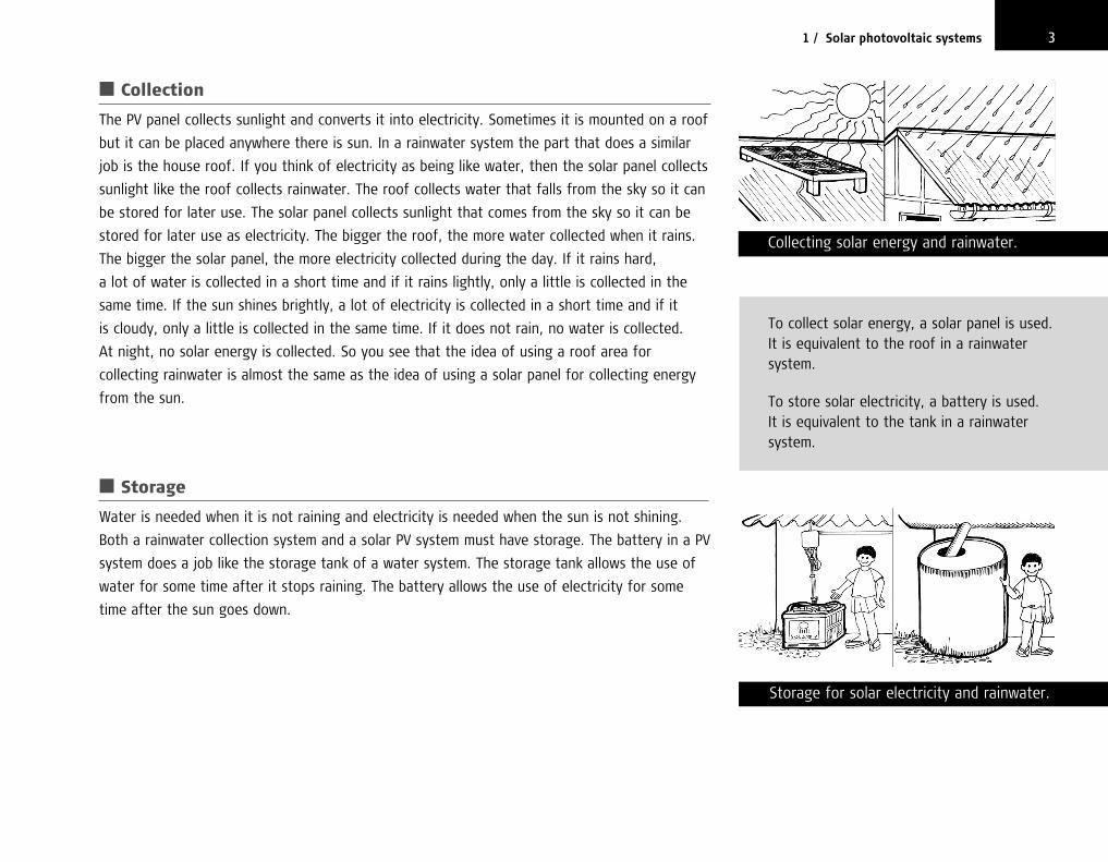
■ Collection
The PV panel collects sunlight and converts it into electricity. Sometimes it is mounted on a roof
but it can be placed anywhere there is sun. In a rainwater system the part that does a similar
job is the house roof. If you think of electricity as being like water, then the solar panel collects
sunlight like the roof collects rainwater. The roof collects water that falls from the sky so it can
be stored for later use. The solar panel collects sunlight that comes from the sky so it can be
stored for later use as electricity. The bigger the roof, the more water collected when it rains.
The bigger the solar panel, the more electricity collected during the day. If it rains hard,
a lot of water is collected in a short time and if it rains lightly, only a little is collected in the
same time. If the sun shines brightly, a lot of electricity is collected in a short time and if it
is cloudy, only a little is collected in the same time. If it does not rain, no water is collected.
At night, no solar energy is collected. So you see that the idea of using a roof area for
collecting rainwater is almost the same as the idea of using a solar panel for collecting energy
from the sun.
■ Storage
Water is needed when it is not raining and electricity is needed when the sun is not shining.
Both a rainwater collection system and a solar PV system must have storage. The battery in a PV
system does a job like the storage tank of a water system. The storage tank allows the use of
water for some time after it stops raining. The battery allows the use of electricity for some
time after the sun goes down.
31 / Solar photovoltaic systems
Storage for solar electricity and rainwater.
To collect solar energy, a solar panel is used.It is equivalent to the roof in a rainwatersystem.
To store solar electricity, a battery is used. It is equivalent to the tank in a rainwatersystem.
Collecting solar energy and rainwater.
chapter1.qxd 11/8/03 11:51 AM Page 3

If it rains a lot and no one uses much water, the storage tank fills up to capacity.
If the sun shines a lot and there is little use of electricity then the battery becomes full
of electricity.
If people use water when there is little rain, the water level in the tank gradually falls and
the tank soon empties. If people use electricity when there is little sun, the amount of
electricity in the battery gradually falls and soon the battery has no more electricity.
■ Flow control
Water storage tanks have valves on their outlet pipes to control the use of water. PV systems
have a controller between the battery and appliances to control the use of electricity. Such a
controller is called a discharge controller because it controls the amount of electricity coming
out of the battery, or discharging. The discharge controller prevents damage to the battery
from too much discharge.
Some water storage tanks also have valves on their inlet to prevent them from becoming too
full and overflowing. Most PV systems have a controller between the panel and the battery to
keep the battery from receiving too much electricity. It is called a charge controller because
it controls the amount of energy going into, or charging, the battery. Batteries can be
damaged from too much charge, so the charge controller is needed to prevent damage
from overcharging.
Usually the charge controller and the discharge controller are combined into one box that is
just called a controller.
4 Solar Photovoltaic Systems Technical Training Manual
Water is moved through pipes, electricitythrough wires.
Flow controls for water and electricity.
SOMETHING VERY IMPORTANT ABOUT PV SYSTEMS
If you use water from the tank faster than rainfalling on the roof refills it, the tank will rundry and you will have to wait until it rains againbefore you have water. If you use electricityfaster than the sun shining on the photovoltaicpanels can refill the battery then the batterywill run out of electricity (discharge). There willbe no more electricity for a day or more untilthe sun can recharge the battery.
chapter1.qxd 11/8/03 11:51 AM Page 4

■ Appliances
Various appliances can use water from the rainwater system or electricity from the
PV system. In rainwater collection systems, there is often only one appliance attached to the
system: a tap. Some water systems may include other appliances such as flush toilets and
showers. Appliances that use a lot of water, such as flush toilets, only work well if connected to
a water system that is designed for them. If a flush toilet is attached to a water system
designed for a simple water tap, it will probably not work well and the storage tank may run
dry quickly.
In PV systems, lights are the most common appliances. But it is possible to connect other
appliances such as radios, televisions, videos, pumps and even refrigerators if the PV system
is designed for them. But if a refrigerator, pump or video is connected to a solar PV system
designed only for lights, it will not work well and the battery will discharge quickly.
■ Transport
Both water and electricity have to be moved from place to place. To move water from one
place to another, pipes are used. To move electricity from one place to another, wires are used.
Large pipes let water flow more easily than small pipes, so large pipes are needed when large
amounts of water are to be moved quickly. Large wires let electricity flow more easily than
small wires and are used when large amounts of electricity are to be moved quickly.
If pipes are not joined together correctly, they leak and all the water does not reach
the appliance. If wires are not joined together correctly, all the electricity does not reach the
appliance where it is needed.
51 / Solar photovoltaic systems
A shower is a water appliance, a light is an electrical appliance.
Rainwater system. Photovoltaic system.
Wires in a solar PV system are like pipes in a rainwater system.
Appliances are the end users of water in a rainwater system and of electricity in a PV system.
chapter1.qxd 11/8/03 11:51 AM Page 5

SUMMARY
Remember that a PV system acts like a rainwater collection system but with electricity instead
of water. If you do not understand something about a PV system, think of it as a water system
and it will be easier to understand.
6 Solar Photovoltaic Systems Technical Training Manual
Rain < Source > SunlightRoof <Collection> PanelsValves < Control > ControllerTank < Storage > BatteryPipes <Transport> WiresAppliances < Use > Appliances
RAINWATER PV
chapter1.qxd 11/8/03 11:51 AM Page 6

INTRODUCTION
You may have some difficulty understanding electricity because you cannot see it.
Fortunately, electricity has many things in common with water so understanding
how water acts in a water system helps in understanding how electricity acts in
a PV system.
To understand a water system, there are a few things that you should know.
Things such as how much water there is, how much force is pushing the water through
the pipe and how much water is flowing through the pipe over a certain time.
It is important to measure these things in a water system, just as it is to measure
similar things in an electrical system.
PRESSURE
Water pressure is a measure of the force that pushes water through a pipe.
Each country has its own method of describing pressure. Units such as pounds per
square inch, kilograms per square metre and pascals are used. Although they have
different names, they all are a measure of water force. One common measure
of water pressure is kilograms per square centimetre (kg/cm2). A water pressure
measurement of kg/cm2 is very low and might be found at the outlet to 13
7
2Electricity
Pressure is the force behind movement ofwater or electricity. In a water system thepressure increases with tank height.
Water systems and solar systems work in avery similar way. The ideas of pressure, flowrate, volume, resistance to flow, power andenergy are almost the same for water andelectricity. The problem with electricity is thatyou cannot see it. But you can see water,therefore in order to better understand anelectrical system, you can think of a similartype of water system and how it acts.
chapter2.qxd 11/8/03 11:52 AM Page 7

a rainwater storage tank standing on the ground. Low pressures are all right when the
water is being used very close to the storage tank. A pressure of 10 kg/cm2 is high
and might be found at the outlet of a pump driven by a diesel engine, or the outlet
of a tank on a high tower. It takes a lot of force to move water through long pipes,
so high pressures are needed when water must be moved long distances.
Electrical pressure is the force that pushes electricity through a wire. The measure
of electrical pressure is the same everywhere. It is measured in volts (V). A low
electrical pressure of 1½ V is the pressure provided by one dry cell as used in
an electric torch or radio. A medium electrical pressure of 120 V to 240 V is found at
electrical power points in city homes. High voltages of more than 1,000 V are needed
to move electricity long distances or for providing very high power. Most home
PV systems operate at 12 V.
VOLUME
The amount of water in a tank is its volume. Many different measures of water volume
are used. The litre (l) is the measure of volume used in most countries. Another
common measure of volume is the gallon. A household rainwater tank may hold
4,000 litres. Another measure of volume is the cubic metre (m3). 1 m3 is the same
volume as 1,000 litres.
There are also several measures of electrical volume, such as the coulomb (C).
A torch cell may hold an electrical volume of 1,500 C. A solar battery may hold an
electrical volume of 360,000 C. Another more common measure of electrical volume
is the ampere-hour (Ah). An electrical volume of 1 Ah is the same as an electrical
volume of 3,600 C, so a battery holding 360,000 C is the same size as a battery that
holds 100 Ah.
8 Solar Photovoltaic Systems Technical Training Manual
Electrical pressure is measured in volts.
Water volume is determined by the size of the tank. It is measured in litres.
The amount of electrical pressure (voltage)needed increases with the amount of power needed and the distance from thesource to the load.
A 1.5 V battery for a torch has a low voltageand can only provide a small amount of powerclose by.
A 12 V battery can provide moderate amountsof power close by.
With 240 V, larger amounts of power can bedelivered over longer distances.
250 litres 2,000 litres
chapter2.qxd 11/8/03 11:52 AM Page 8

FLOW RATE
When water moves through a pipe, it is said to flow. The volume of water (gallons,
litres or cubic metres) that flows through a pipe in one unit of time (1 second,
1 minute or 1 hour) is called the flow rate. It is often measured in litres per minute or
gallons per hour. A pipe from a rainwater tank may have a flow rate of 10 litres/minute
when a tap is turned on, while a pump driven by a diesel engine may give a water flow
rate of 1,000 litres/minute.
When electricity moves through a wire, it is sometimes said to flow like water but
it is usually said to have a current rather than a flow rate. So electricity moving
through a wire is called an electric current and is measured in amperes (A). 1 A is
a volume of 1 C flowing through a wire over a time of 1 second. So an ampere is a
one-coulomb-per-second flow rate. 1 A is also the average current when 1 Ah of
electrical volume flows through a wire over a period of 1 hour. The current that flows
through a solar-powered light may be less than 1 A, while that needed to run a large
solar-powered video may be 30 A.
RESISTANCE
Electricity flows through wires like water flows through pipes. Pipes allow water to be
carried from one place to another just as wires allow electricity to be carried from
place to place.
With water, the longer the pipe the lower the flow of water that a particular
pressure can push through the pipe. For a given pressure, a very long pipe will have a
much lower flow of water than a short one of the same size. This is because the longer
92 / Electricity
Electrical volume is determined by the size and type of battery. It is measured incoulombs or ampere-hours.
The smaller the pipe, the greater theresistance to water flow.
360,000 coulombs or100 ampere-hours 1,500 coulombs or
42 ampere-hours
The smaller the wire, the greater theresistance to electricity flow.
chapter2.qxd 11/8/03 11:53 AM Page 9

the pipe, the more difficult it is to push water through the pipe. It is as if a very long
pipe pushes back with a force against the flow of water. This force that opposes the
flow of water is called flow resistance or just resistance. The resistance to water flow in
a pipe increases in step with the length of the pipe, so a pipe twice as long resists flow
twice as much. We say that it has a resistance of twice as much.
It is also harder to push water through a small pipe than a large one. The resistance
increases in step with the decrease in the amount of space for the water to flow.
The space for flow in a pipe is also called cross-sectional area or cross-section. It is
usually measured in square centimetres (cm2) or square inches (in2). If a pipe has
a cross-section of 5 cm2, it will have twice the resistance to water flow as a pipe of
the same length that is 10 cm2 in cross-section.
Make sure that you understand the difference between the diameter of a pipe and the
cross-sectional area of a pipe. The diameter is the distance across the end of the pipe.
The cross-sectional area is the total space available across the end of the pipe for water to
flow. It is important to realize that if you double the diameter of a pipe, the cross-sectional
area of that pipe is four times larger, not two times larger. The reason is that when you
increase the diameter of the pipe in one direction, the diameter is also increased in the
other direction because the pipe is round. If you double the diameter of the pipe in only one
direction and therefore double the cross-section, the pipe would not be round, it would
be a flattened oval. This means that if you change 100 m of 20 mm diameter pipe for
40 mm diameter pipe, the resistance is four times smaller because the cross-section of
the 40 mm diameter pipe is four times larger than the cross-section of the 20 mm pipe.
Electricity flowing through a wire acts in the same way as water flowing through a pipe.
If the wire length is doubled, the resistance of the wire is also doubled and it is twice as
hard to force electricity through the wire. If the wire size (cross-sectional area) is cut in
half, the resistance is doubled and it is twice as hard to push electricity through the wire.
10 Solar Photovoltaic Systems Technical Training Manual
Resistance to the flow of water increases asthe length of the liquid flow path increases.
Resistance to the flow of electricity increasesas the length of the electricity flow pathincreases.
chapter2.qxd 11/8/03 11:53 AM Page 10

With water, if the pressure stays the same and the pipe length is doubled, the flow
rate is cut in half. In other words, if you want to keep the same flow rate through
a pipe whose length has doubled — which makes the flow resistance also double — you
have to double the pressure.
Looking at this differently, if you find that you have to double the length of a pipe
and cannot change the pressure that forces the water through the pipe, then the
only way you can keep the same flow rate as before is to cut the resistance to flow in
half. To do this, lay an identical pipe alongside the first one and join them together.
This gives double the space for water to flow and cuts the resistance in half. Another
way is to take out the old pipe and put in a single new pipe with double the
cross-sectional area of the old one.
This relationship can be stated as follows:
water pressure equals flow rate times flow resistance.
Or, in another way:
water flow rate equals pressure divided by flow resistance.
Or, in a third way:
water flow resistance equals pressure divided by flow rate.
Therefore if you know any two of the three terms, resistance, pressure or flow rate,
you can easily calculate the third.
Electricity acts in the same way. If wire length (resistance) is doubled and voltage
(electrical pressure) kept the same, the amperes flowing (electrical flow rate) are cut in
half. If voltage is kept the same and wire length doubled, you can only have the same
current by cutting the wire resistance in half. This can be done by doubling up the wire
with another of the same size, or by replacing the old wire with a wire that has twice
the cross-sectional area.
There is no common term or unit for measurement of pipe resistance but the unit
used in measuring electric resistance is the ohm (�).
112 / Electricity
Example 1
A voltage of 12 V forces a current (flow of electricity) of 4 A through an unknown resistance. What is the resistance in ohms?
Resistance = volts ÷ amperes= 12 ÷ 4= 3 �
Example 2
A resistance of 6 � is placed across a voltageof 24 V. What current flows?
Current = volts ÷ ohms= 24 ÷ 6= 4 A
Example 3
A resistance of 3 � is measured to have a current of 2 A flowing through it. Whatvoltage is there across the resistance?
Volts = amperes × ohms= 2 × 3= 6 V
chapter2.qxd 11/8/03 11:53 AM Page 11

12 Solar Photovoltaic Systems Technical Training Manual
The relationship between volts, amperes andohms is usually stated as a formula:
E = IRwhere E stands for volts (from the French termfor electrical pressure: ‘electromotive force’), Istands for amperes (from the French term forelectrical flow rate: ‘electrical intensity’) and Rstands for ohms (resistance). The sameformula can be rearranged so if any two of thethree terms are known, the third can becalculated. To help remember the formulas, a circle diagram is used to represent the threeways to state the formula:
E = IR, I = E/R, R = E/I.
E
I R
The interaction between electrical pressure in volts, electrical flow rate in amperes
and flow resistance in ohms is:
volts equals amperes times ohms.
This is the electrical equivalent of:water pressure equals flow rate times flow resistance.
Or, put another way:amperes equals voltage divided by ohms.
This is the electrical equivalent of:water flow rate equals pressure divided by flow resistance.
Or, in a third way:ohms equals voltage divided by amperes.
This is the electrical equivalent of:
water flow resistance equals pressure divided by flow rate.
Therefore if you know any two of the three units, amperes, volts or ohms, you can
always calculate the third.
POWER
Power is the ability to do work. A powerful machine can do a lot of work. Anyone
living near the ocean knows the power of moving water. If you have ever had to swim
against an outflowing tide, you know that there is power even in slowly moving water.
If the water volume is high and the flow rapid, as with high breakers along the reef or
a fast-flowing river, the power is great and can injure or even kill you.
If you place your hand in flowing water, you can feel the force pushing against your
hand. The flow of water is producing a small amount of power. If the water is under
chapter2.qxd 11/8/03 11:53 AM Page 12

high pressure or a large volume of water is flowing, the pressure on your hand is
greater and we say that there is more power. So the power increases if either the
water pressure or the water flow rate increases.
Think about the water flow from the tap on a rainwater tank. If it is barely turned
on and there is little flow, the force on your hand under the tap is low. If you open the
tap all the way, the power is greater. The power increases in step with the flow rate.
If the flow rate doubles, the power doubles.
Also, if the tank is nearly empty and the pressure very low, the force on your
hand is also low. If the tank is full and the water pressure high, the force is also high.
The power provided by the flow of water increases in step with the pressure. If the
pressure doubles, the power doubles.
So the power from a stream of water increases both with increased flow rate and
increased pressure. If both the pressure and the flow rate double, the total power is
raised four times; twice from the doubling of flow rate and twice again from the
doubling of pressure. So power equals flow rate times pressure.
Electrical power works in the same way. If the pressure (volts) doubles and the flow
rate (current in amperes) stays the same, the power doubles. If the current triples
and the voltage stays the same, the power triples. If the voltage doubles and the
current triples, the power increases six times. Electrical power equals flow rate in
amperes times pressure in volts.
The measure used for electrical power is the watt (W). 1 W is the power produced
by a current of 1 A driven by an electrical pressure of 1 V. If the electrical pressure
of a PV system is 12 V and it operates a light that uses 2 A, the power used is
12 V × 2 A = 24 W.
132 / Electricity
Power depends on the pressure.
Power depends on the flow rate.
chapter2.qxd 11/8/03 11:53 AM Page 13

Remember that electrical power in watts is voltage times amperage, just as water
power is pressure times flow rate.
So if you know the power in watts you can find the current in amperes if you divide
watts by volts. If you know the wattage, you can find the voltage if you divide watts
by amperes.
ENERGY
The terms power and energy are often confused. Power is the ability to do work.
Energy is the total actual work that is done. A large, strong man may have great
power but if he is lazy and sleeps all day, he does little work and produces little
energy.
To see the difference between power and energy, think of an outboard motor.
The power of an outboard motor is measured in horsepower. A 40 horsepower outboard
has twice the power of a 20 horsepower model. You might think that the 40 horsepower
motor provides twice the energy of the 20 horsepower unit but that is not necessarily
true. Remember that energy is a measure of actual work done. Even though something
is powerful, little work may be done because the power is used for only a short time.
If a 24 W light is connected to a 12 V source of electricity, how much current
will flow?
12 V × ?? A = 24 W
24 ÷ 12 = 2 A
14 Solar Photovoltaic Systems Technical Training Manual
If the flow rate doubles and the pressuretriples, what happens to the power?
2 × 3 = 6
The power goes up six times.
If the flow rate doubles and the pressure is cut by half, what happens to the power?
2 × ½ = 1
The power is the same.
Example 1
A video uses 30 A at 12 V. Its powerrequirement in watts is:
30 A × 12 V = 360 W
Example 2
A pump uses 10 A at 48 V. Its powerrequirement in watts is:
10 A × 48 V = 480 W
Example 3
A light uses 1.5 A at 12 V. Its powerrequirement is:
1.5 A × 12 V = 18 W
Example 4
If a refrigerator using 120 W requires a currentof 10 A, what voltage is present?
?? V × 10 A = 120 W
120 W ÷ 10 A = 12 V
chapter2.qxd 11/8/03 11:53 AM Page 14

A strong man who sleeps most of the day does much less work than a weak man who
labours all day. A 40 horsepower motor operated for a few minutes moves a boat only
a short distance while a 20 horsepower motor operated all day will move the same boat
a long distance. But the 40 horsepower motor will move a boat much further than a
20 horsepower motor during the same time. The energy produced depends both on the
power available and on the length of time the power is applied. Multiplying the power by
the time the power is used gives the amount of energy. As the electrical measure of power
is the watt, in electrical terms energy is measured as watts times hours or watt-hours (Wh).
An electrical appliance that delivers a power of 5 W for 2 hours provides
5 × 2 = 10 Wh of energy. If a light requires 20 W to operate and is run for 4 hours,
the energy used is 20 × 4 = 80 Wh.
Because it is energy that the solar panels provide to the battery and energy that
goes to the appliances from the battery, it is the flow of energy, not the power,
that determines how large the panels and batteries must be. An appliance, such as
a small light, that uses little energy in an hour can operate many hours from a charged
battery. An appliance that uses a lot of energy in an hour, such as a large colour
television, will operate only a short time from the same charged battery.
CIRCUITS
A piping system for rainwater may be simply a short pipe with a tap at the end or it
may have many branches going to different places. The pipe and its connections are
called a water circuit. For water to flow all the way from the tank to the appliance
152 / Electricity
With a particular battery, the amount oftime an appliance will run depends on itspower needs.
Starting with a battery that holds 1,200 watt-hours of electricity:
A 60 Wrefrigerator willrun for 20 hours
A 25 watt TVwill run for48 hours
And a 12 W light willrun for 100 hours
The amount of energy used depends onboth the power and the amount of time itis used. This outboard motor is out ofenergy (fuel) because the engine was runfor too long.
chapter2.qxd 11/8/03 11:53 AM Page 15

there must be a continuous pipe connecting them. If the pipe is disconnected or
broken, the water will not flow to the appliance and it will not work.
A drawing of a water circuit, showing the water source, the pipe paths and
connections and the appliances, is called a plumbing circuit diagram. On the diagram
you can trace the flow of water from source to appliance.
Like water circuits, electrical circuits for PV systems can be very simple with a
battery joined to a light. A circuit can also be complex with several batteries and many
appliances all joined together. When electrical elements, such as batteries, resistances,
motors and appliances, are connected with wires, an electrical circuit is created.
There is one big difference between the way a water circuit and an electrical circuit
work. A water circuit usually ends with the appliance and the water flowing away into
a drain. In an electrical circuit, the electricity cannot flow outside a wire, so there must
be a wire to carry electricity away from the appliance as well as a wire to carry
electricity to the appliance. This return wire goes back to the power source, where the
returned electricity is pumped back up to full voltage and sent back to the appliance.
In an electrical circuit, the electricity must have a continuous path not only to the
appliance but also from the appliance back to the source. If the path is broken at any
point, the flow of electricity stops. If a continuous path does not exist, then we say
that the circuit is open. If a continuous path is present, then the circuit is closed.
Electricity will flow through a closed circuit but will not flow through an open circuit.
A switch is an electrical device that allows you to open or close a circuit to turn the
electricity flow off or on.
16 Solar Photovoltaic Systems Technical Training Manual
For electricity toflow there must bea continuous path. The circuit must be closed.
It is important to know the polarity andobserve it when connecting wires in a PV electrical system.
Connecting the wrong poles can causedamage, a fire or even an explosion.
In a water systemthere is usually noreturn pipe, sothe circuit is saidto be open.
chapter2.qxd 11/8/03 11:53 AM Page 16
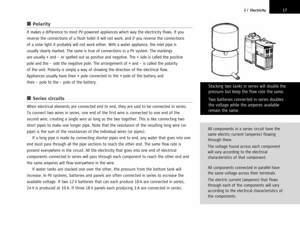
■ Polarity
It makes a difference to most PV-powered appliances which way the electricity flows. If you
reverse the connections of a flush toilet it will not work, and if you reverse the connections
of a solar light it probably will not work either. With a water appliance, the inlet pipe is
usually clearly marked. The same is true of connections in a PV system. The markings
are usually + and – or spelled out as positive and negative. The + side is called the positive
pole and the – side the negative pole. The arrangement of + and – is called the polarity
of the unit. Polarity is simply a way of showing the direction of the electrical flow.
Appliances usually have their + pole connected to the + pole of the battery and
their – pole to the – pole of the battery.
■ Series circuits
When electrical elements are connected end to end, they are said to be connected in series.
To connect two wires in series, one end of the first wire is connected to one end of the
second wire, creating a single wire as long as the two together. This is like connecting two
short pipes to make one longer pipe. Note that the resistance of the resulting long wire (or
pipe) is the sum of the resistances of the individual wires (or pipes).
If a long pipe is made by connecting shorter pipes end to end, any water that goes into one
end must pass through all the pipe sections to reach the other end. The same flow rate is
present everywhere in the circuit. All the electricity that goes into one end of electrical
components connected in series will pass through each component to reach the other end and
the same amperes will flow everywhere in the wire.
If water tanks are stacked one over the other, the pressure from the bottom tank will
increase. In PV systems, batteries and panels are often connected in series to increase the
available voltage. If two 12 V batteries that can each produce 10 A are connected in series,
24 V is produced at 10 A. If three 18 V panels each producing 3 A are connected in series,
172 / Electricity
All components in a series circuit have thesame electric current (amperes) flowingthrough them.
The voltage found across each component will vary according to the electricalcharacteristics of that component.
All components connected in parallel havethe same voltage across their terminals.
The electric current (amperes) that flowsthrough each of the components will varyaccording to the electrical characteristics ofthe components.
Stacking two tanks in series will double thepressure but keep the flow rate the same.
Two batteries connected in series doublesthe voltage while the amperes availableremain the same.
chapter2.qxd 11/8/03 11:53 AM Page 17

54 V at 3 A is produced. The voltage from batteries or panels connected in series is the sum
of the individual voltages. The amount of amperes produced is the same as from one battery
or panel.
■ Parallel circuits
When electrical components are connected side by side, they are said to be connected in
parallel. To connect two wires in parallel, one end of each wire is joined together then the
other ends of each wire are joined together. The result is two wires side by side with their
ends connected.
This is like laying two small pipes side by side then joining them at both ends. When the
water is turned on, part of it flows through one pipe and part through the other. The flow
is split. If one pipe is large and the other is small, more water will flow through the large
pipe than the small one. This is because the same pressure is present in both pipes but
their resistances are different. The same thing happens in a parallel electrical circuit: the
electrical flow is split among each of the branches according to the flow resistance of
each branch.
If several water tanks are set side by side and interconnected, the pressure will be the
same as from one tank but the flow of water will be increased. In PV systems, batteries
and panels are sometimes connected in parallel to increase the available current. If two
12 V batteries that can each produce 10 A are connected in parallel, 12 V is produced with
a possible 20 A of current. If three 18 V panels each producing 3 A are connected in parallel,
18 V at 9 A is produced. The voltage from batteries or panels connected in parallel is the
same as that produced by one unit. The amount of amperes produced is the sum of the
individual currents.
18 Solar Photovoltaic Systems Technical Training Manual
Two tanks connected in parallel deliver twicethe flow at the same pressure.
Two batteries wired in parallel deliver twicethe amperes at the same voltage.
chapter2.qxd 11/8/03 11:53 AM Page 18

ALTERNATING CURRENT (AC)
The electricity that we have discussed so far can be thought of as flowing directly
from a source (such as a battery) through wires to the point of use (such as a light).
This type of electrical power is called direct current (dc). Solar panels and batteries
produce dc electricity.
The electrical power provided by engine-driven rotating generators, from the smallest
portable generator up to the largest city power plant, is usually not direct current.
This type of electrical power flows in one direction for a short time then reverses to
flow in the other direction an equally short time before reversing again. It is called
alternating current (ac) because the electricity constantly alternates its direction of flow.
The forward and backward repetition of direction is called a cycle and the number of
cycles that occur in 1 second is called the ac frequency. Frequency is measured in hertz
(Hz). Power-plant frequencies are either 50 Hz or 60 Hz, depending on the power
standards of the country.
Alternating current power can be converted to direct current using a rectifier. Direct
current can be converted to alternating current using an inverter. These conversions
cannot be made without the loss of some power and, unless care is taken, the power
produced may be of poor quality.
Unlike dc, ac has no polarity. This is because polarity indicates the direction of
electrical flow and in an ac system the flow reverses many times a second.
Which is better, ac or dc power? Both have advantages and disadvantages. Large
power systems commonly use ac, while dc power is more efficient to transport and use
but more difficult to produce in large quantities, and operating voltages are difficult
192 / Electricity
Electricity from solar photovoltaic panels isdirect current (dc). It does not changevoltage or polarity.
240 V
240 V
1/50 second
+
-
Electricity from city generators isalternating current (ac). The voltagechanges constantly and the polarityreverses many times a second.
chapter2.qxd 11/8/03 11:54 AM Page 19

to change. The decision whether to use ac or dc is usually based on what technology
is to be used to create the power. Home appliances designed to operate on dc do
exactly the same job as those designed to work on ac and both are widely available,
though ac appliances are more common. As solar panels produce dc, that is the usual
choice for solar PV systems. In a few cases where dc appliances are hard to find, an
inverter to convert solar-generated dc to ac may be used. Such conversions should
be avoided where possible because of the added cost of the inverter and its use of
additional electrical energy for its own operation.
CONCLUSION
Electricity flowing through wires acts in many of the same ways as water flowing
through pipes. Whenever you are confused or have a problem understanding electricity,
think about how a similar water system would work. Remember that electrical pressure
is measured in volts, electrical flow rate in amperes and electrical resistance to flow in
ohms. The units of power and energy are watts and watt-hours and those same units
are used both for water power and water energy and electrical power and electrical
energy.
20 Solar Photovoltaic Systems Technical Training Manual
chapter2.qxd 11/8/03 11:54 AM Page 20

INTRODUCTION
In a PV system, the part that converts sunlight to electricity is called a photovoltaic
panel (PV panel). It is expensive and very difficult to make, but simple to use. All you
have to do to make electricity is to place it in the sun.
PANEL CONSTRUCTION
Most solar panels normally used for power production in rural areas are made
up of a number of individual cells. The cells may be round, square or some other
shape.
Each cell produces about ½ volt, no matter what its size. The amount of amperes
a cell can produce does depend on its size, with larger cells producing more
amperes.
As each cell only produces about ½ volt, many cells have to be connected in
series to produce a high enough voltage to charge a 12 V battery. Usually
there are from 30 to 36 of these cells on a panel that is intended to charge
a 12 V battery, to make sure that the maximum voltage from the panel is high
enough.
21
3Photovoltaic panels
AMORPHOUS PANELS
You may see solar panels that do not haveindividual cells. These are a newer type called amorphous silicon or thin-film panels.Their use is increasing, particularly for smallPV systems. There is still uncertainty abouthow long they last. For remote rurallocations where very long life and highreliability is needed, panels with individualcells are by far the most popular.
chapter3.qxd 11/8/03 11:55 AM Page 21

Because panels with less than 33 cells do not charge a 12 V lighting system
battery quickly enough in the tropics, no panels should be used that do not have
at least 33 cells, and panels with 34 to 36 cells are better.
Panels with more than 36 cells will also work well. Unfortunately, they cost more and
do not provide any advantage over 36-cell units for battery charging. The extra cost for
panels that have more than 36 cells is not justified for charging a 12 V battery.
WHAT AFFECTS ELECTRICITY OUTPUT
■ Effect of panel area
Just as a large roof collects more water than a small one, the larger the solar panel, the more
electricity is produced. If you double the amount of surface covered by panels, the electricity
output is doubled.
■ Effect of sun’s brightness
The harder it rains, the more water you obtain from a roof. PV panels work the same way with
the sun. The more sunlight that falls on the panel, the more electricity is produced. If there is
shade on a panel, the electricity output falls greatly.
■ Effect of panel direction
If you stand in a rainstorm with a strong wind blowing, the side of you facing the wind gets
much wetter than the side away from the wind. To get the most electricity from a solar panel,
it must be facing the sun.
22 Solar Photovoltaic Systems Technical Training Manual
Panels are made up of many individual cellsconnected in series. The big panel has 34 cellsand is for 12 V systems.
The small 17-cell panel is for 6 V systems. Thelarger the panel, the greater the electricalenergy produced.
For best results, there should be no shade ona solar panel between 09:00 and 15:00. Evenif only one cell is shaded, the output can becut by half or even more.
chapter3.qxd 11/8/03 11:55 AM Page 22

■ Effect of heat
You work better if you are not too hot. Solar panels also work best when kept cool. The hotter
the panel, the less power it provides.
GETTING THE MOST ELECTRICITYFROM A PANEL
Because PV panels are expensive, try to get as much electricity from them
as you can.
■ Make sure that the brightest sunlight falls on the panel
The brightest sun is where there is no shade. Solar panels lose most of their electricity
output when even a small part of the panel is in the shade. It is very important that solar
panels are placed where the sun will shine on them from at least 09:00 to 15:00 without any
shade at all.
Always remember that the sun shifts its position from north to south over the year as well
as from east to west during the day.
In the tropics, the sun will be more in the northern sky for the months around June and
more in the southern sky for the months around December. So you must pay attention to trees
and buildings both to the north and south of the panel and make sure they will not cause
shade at any time of year.
■ Make sure that the panel faces the sun
Most electricity will come from the panel when it points directly towards the sun. But because
the sun moves across the sky from morning to night, the panel would have to move to always
233 / Photovoltaic panels
The sun not only moves from east to westduring the day, it moves north and southwith the seasons. The sun is furthest northin June when it rises to the north of due eastand sets to the north of due west.
In December it is furthest south and the sunrises to the south of east and sets to thesouth of west.
On 21 March and 21 September the sun risesexactly in the east and sets exactly in thewest.
The sun is always at its highest at noon. Itsheight at noon depends on the time of yearand how far the site is from the equator.
When installing solar panels in the tropics,remember that sometimes the sun is in the northern sky and sometimes it is in thesouthern sky. A location that may be in the sun all day in June may be shaded all day in December.
chapter3.qxd 11/8/03 11:56 AM Page 23

face the sun. This is not practical in most places and the best we can do is to fix the panel
facing in the direction where the sun is located when it is brightest. The sun is brightest at
noon. The location of the sun at noon depends on the time of year and how far you are from
the equator. The best mounting for a solar panel is with a tilt towards the equator equal to the
latitude of the location. Thus a panel located at a site with a latitude of 12 degrees north of
the equator should be mounted with a tilt of 12 degrees facing towards the south. A panel
located at a site with a latitude of 18 degrees south of the equator would be best mounted
with a tilt of 18 degrees towards the north. A panel mounted on the equator should have a tilt
of 5 degrees towards any direction. A small tilt of 5 to 10 degrees is always needed to let rain
wash off any dirt from the panel.
In the tropics when the latitude is less than 15 degrees, you do not have to be highly
accurate in pointing the panel towards the equator. At latitudes higher than 15 degrees,
the panel needs to be carefully pointed towards the equator to get the best power output.
■ Keep the panel as cool as possible
Because solar panels must be in the bright sun, it is difficult to stop them from getting hot.
It helps if solar panels are mounted so that the wind can blow over both the top and bottom
of the panels. That means they should not be mounted directly on a roof but at least
10 cm above the roof, so that air can move all around the panels and cool them.
ARRAYS OF MORE THAN ONE PANEL
Most people want more power than a single solar PV panel can provide. To increase the
power available, panels may be joined together. Panels can be connected in two ways:
series connections or parallel connections.
24 Solar Photovoltaic Systems Technical Training Manual
THREE RULES TO GET THE BEST OUTPUT FROM SOLAR PANELS
Rule 1
There should be no shade on the panelbetween 09:00 and 15:00.
Rule 2
Tilt the panel at an angle equal to the latitudeof the site, though it should never be tiltedless than 5 degrees from horizontal. The panelshould face north for sites south of theequator and it should face south for sitesnorth of the equator.
Rule 3
Mount the panel at least 10 cm above othersurfaces so air can easily cool the back of thepanel.
chapter3.qxd 11/8/03 11:56 AM Page 24

■ Series-connected panels
When more voltage is needed than a single panel can provide, additional panels are connected
in series. If one panel provides 12 V, two in series will provide 12 + 12 or 24 V. Three in series
will provide 12 + 12 + 12 or 36 V. For every 12 V panel connected in series to other 12 V panels,
the voltage will increase by another 12 V.
The amount of amperes provided by panels in series is the same as that provided by
one panel because the same electricity flows through all the panels, as they are connected
in one long line. Each panel increases the electrical pressure but the flow stays the same
as with one panel. As power in watts equals volts times amperes, the power increases as
panels are added.
■ Parallel-connected panels
When the voltage from a single panel is the amount needed but there is not enough current,
panels can be connected in parallel. If one panel provides 2 A in bright sunlight, two in parallel
will provide 2 + 2 or 4 A. For each of these 2 A panels connected in parallel, an extra 2 A will be
produced in bright sunlight.
With parallel-connected panels, the voltage remains the same as with one panel but the
amperage increases with each additional panel. As power in watts equals volts times amperes,
the power increases as panels are added.
Note that for both series- and parallel-connected panels, the power increases as the number
of panels is increased. Two panels in parallel produce the same power as two panels in series,
but the voltage and amperage are different.
253 / Photovoltaic panels
Two panels are connected in parallel byconnecting terminals of the same polarity.The amperage is doubled but the voltage isthe same as one panel.
Two panels are connected in series byconnecting the positive of one panel to thenegative of the other. The result is doubledvoltage but the same amperage as one panel.
chapter3.qxd 11/8/03 11:56 AM Page 25
■ Series-parallel connections
Solar PV systems to power refrigerators and other large appliances often use a 24 V battery
instead of a 12 V battery. Some even use 48 V batteries. As solar panels are almost always
designed to charge 12 V batteries, two panels have to be connected in series to charge a
24 V battery and four panels have to be connected in series to charge a 48 V battery. Often
more amperes are needed than one panel can provide, so panels have to be connected in
parallel as well. This combination of series and parallel connections can be extended to as high
a voltage as needed by adding more panels in series and as high an amperage as needed
by adding more panels in parallel.
There are many different ways of connecting a large number of panels correctly to get
the desired voltage and amperage. You can connect panels in series until the voltage
is reached then connect more series-connected sets of panels in parallel until the
amperage is reached.
You can also connect panels in parallel to get the amperes needed then connect more
parallel-connected sets of panels in series to get the desired voltage. Perhaps this should be
called a parallel-series connection, but it really does not matter because the final voltage and
amperage are the same as in a series-parallel connection.
CONNECTING PANELS WITH DIFFERENT CHARACTERISTICS
■ Series connections
If PV panels with different voltage and current (amperage) characteristics are connected in
series, their voltages should be totalled just as when identical panels are connected in series.
So if one panel that produces 16 V and another that produces 17 V under the same conditions
are connected in series, the resulting voltage is 16 + 17 = 33 V.
However, the current available at maximum power will be limited by the panel with the
lowest ampere capacity. Series-connecting a panel that by itself can produce 2 A with another
that by itself can produce 3 A under the same conditions will result in a current of just over
26 Solar Photovoltaic Systems Technical Training Manual
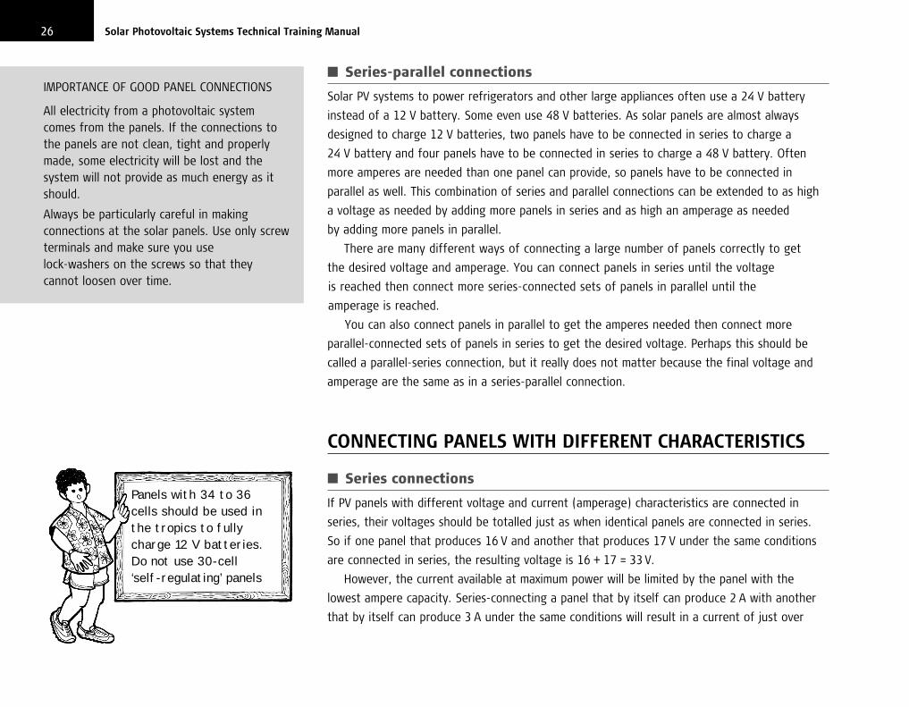
Panels with 34 to 36cells should be used inthe tropics to fullycharge 12 V batteries.Do not use 30-cell ‘self-regulating’ panels
IMPORTANCE OF GOOD PANEL CONNECTIONS
All electricity from a photovoltaic systemcomes from the panels. If the connections tothe panels are not clean, tight and properlymade, some electricity will be lost and thesystem will not provide as much energy as itshould.
Always be particularly careful in makingconnections at the solar panels. Use only screwterminals and make sure you use lock-washers on the screws so that theycannot loosen over time.
chapter3.qxd 11/8/03 11:56 AM Page 26

2 A from the two panels. This means that to get the most out of series-connected panels that
are not the same, the closer their ampere ratings match, the better the performance of the pair
will be. As amperes are determined by the size of the cells, panels connected in series work
best if the cells on both panels are the same size.
■ Parallel connections
If PV panels with different voltage and current characteristics are connected in parallel, their
currents should be totalled just as when identical panels are connected in parallel. So if one
panel produces 3 A and the other produces 2 A, the two in parallel will produce 5 A.
However, the voltage available at maximum power from the parallel-connected panels will be
limited by the smaller of the two panel voltages. Parallel-connecting a panel that produces 16 V
with one that produces 17 V under the same conditions results in a voltage a little greater than
that of the 16 V panel. Thus, to get the most out of parallel-connected panels, they should
have the same number of cells and produce about the same voltage.
MOUNTING PANELS
Because solar panels are constantly exposed to wind and weather, it is important that
their mounting is secure and resistant to corrosion or loosening.
Mounting panels on a roof is usually cheaper than mounting them on a pole. But if
the roof is shaded or facing the wrong way, a pole must be used. Pole mounting
provides better cooling for the panels than roof mounting. Pole-mounted panels usually
have to be placed further from the battery than panels mounted on the roof, so will
need larger wires to stop too much power loss through the wiring. The poles should be
273 / Photovoltaic panels
RULES FOR CONNECTING PANELS WITHDIFFERENT ELECTRICAL CHARACTERISTICS
Rule 1
When connecting different panels in series,the number of amperes (the rating) isimportant. The amperes from the seriesstring will be limited to about the ampererating of the panel with the lowest ampereoutput. For best results, ampere ratingsshould be matched for series connections.
As the ampere rating is fixed by the size ofthe individual cells (not their number), panelswith cells of similar appearance will probablywork well together.
Rule 2
When connecting different panels in parallel,the volt rating is important. As the voltrating is fixed by the number of cells (nottheir size), panels with the same number ofcells will probably work well together.
Nails loosen over time. Panels should neverbe mounted with anything but screws orbolts and they should be made fromstainless steel or other material that willnot rust.
chapter3.qxd 11/8/03 11:56 AM Page 27

tall enough to prevent people from touching the bottom of the panels. Burying the
wires is usually better than stringing them overhead, but make sure they are designed
for underground use.
The panels should be attached with stainless-steel bolts or screws, not nails, which
can loosen over time. If the panels are mounted on a pole, it should be set securely in
the ground and anchored to a building if possible.
28 Solar Photovoltaic Systems Technical Training Manual
LatitudeAngle
To Equator
Panel Surface
For most locations, most sunlight is receivedon a panel tilted towards the equator by anamount equal to the latitude of the site.
Horizontal
chapter3.qxd 11/8/03 11:56 AM Page 28

INTRODUCTION
In a water system, it is sometimes important that a storage tank should not become
too full or too empty. A valve can be installed to turn off the water coming into
the tank when the tank gets full. Another valve can be installed to prevent water from
leaving the tank when the level falls too low. These two valves control the amount of
water in the tank.
In a PV system, an electrical valve is usually installed to keep the battery from
getting too full. This is called a charge controller. Another electrical valve is installed to
keep the battery from completely running out of electricity. This is called a discharge
controller. These valves control the amount of electricity in the battery.
CHARGE CONTROLLER
Without a charge controller the panels can force too much electricity into the battery
and overcharge it. When a battery is overcharged, it loses water rapidly, gets hot and
may be damaged. A charge controller works like a valve on a rainwater collection
system that prevents the water tank from overflowing.
29
4Controllers
A charge controller is connected betweenthe battery and the panels.
A discharge controller is connectedbetween the battery and the appliances.
Charge and discharge controllers are oftencombined to make one controller.
Charge Controller
BatteryPanels
DischargeController
Battery
Appliance
Controller
PanelsBattery Appliance
chapter4.qxd 11/8/03 11:58 AM Page 29

The charge controller must be connected between the panels and the battery.
It works by constantly checking the voltage of the battery. If the voltage is so high
that it shows that the battery is full, the controller automatically stops more electricity
from going into the already full battery.
■ Series charge controller
There are two basic types of charge controller. One type is connected in series with the panels.
It is a switch that shuts off electricity flow from the panels to the battery when full charge is
reached. The switching may be done by a magnetic switch called a relay, but special switching
transistors can also be used. A series controller is like a valve in a pipe leading to a tank that
closes when the tank is full.
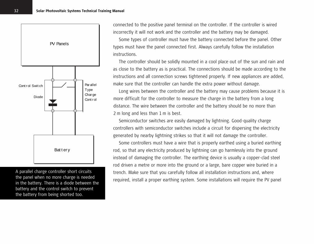
■ Parallel charge controller
The second type of charge controller is connected in parallel with the panels across their output
wires. When it senses that the battery is fully charged, it shorts the panel wires and no more
electricity can reach the battery. Although panels are not damaged by short circuits, batteries
are damaged, so there must be a one-way valve between the controller and the battery to
prevent the controller shorting the battery as well as the panels. This one-way valve is called
a diode. Parallel controllers usually have a semiconductor (transistor) switch instead of a relay.
In a water system, an overflow pipe that allows excess water to flow away when the tank is full
works like a parallel controller.
DISCHARGE CONTROLLER
The discharge controller stops appliances from taking too much electricity from the
battery and discharging it too much. When a battery is too discharged, it loses some of
30 Solar Photovoltaic Systems Technical Training Manual
A series controller is like a valve thatautomatically shuts off the flow of waterwhen a tank is full.
A parallel controller is like an overflow pipe on a tank that stops it from getting too full.
chapter4.qxd 11/8/03 11:58 AM Page 30

its capacity to be recharged, it is weakened and its life is shortened. A discharge
control is like a valve on a rainwater collection system that stops you from taking all
the water from the tank.
The discharge controller must be connected between the battery and the appliances.
It works by continuously checking the voltage of the battery. If the voltage is so low
that it shows that the battery is almost empty, the controller automatically disconnects
the appliances so that no more electricity can be taken from the nearly empty battery.
It is always connected in series with the battery.
COMBINED CHARGE AND DISCHARGE CONTROLLERS
A charge controller and a discharge controller are often placed together in the same
box. You can usually tell what kind of controller is present by looking to see what
connections there are. If the controller box has connections that go to the panels, it
usually means that it includes a charge controller. If the box has connections that go to
the appliances, it usually means that it includes a discharge controller. All controllers
are connected to the battery.
INSTALLATION AND MAINTENANCE OF CONTROLLERS
Wire the controller into the circuit according to the instructions provided by the
supplier of the controller. It is very important that you connect the correct wires to the
correct terminals. The positive wire from the battery must be connected to the positive
battery terminal on the controller. The positive terminal from the panels must be
314 / Controllers
A series charge controller opens the circuitbetween panels and battery when thebattery is full of electricity.
PV Panels
SeriesTypeChargeControl
Battery
ControlSwitch
chapter4.qxd 11/8/03 11:58 AM Page 31
connected to the positive panel terminal on the controller. If the controller is wired
incorrectly it will not work and the controller and the battery may be damaged.
Some types of controller must have the battery connected before the panel. Other
types must have the panel connected first. Always carefully follow the installation
instructions.
The controller should be solidly mounted in a cool place out of the sun and rain and
as close to the battery as is practical. The connections should be made according to the
instructions and all connection screws tightened properly. If new appliances are added,
make sure that the controller can handle the extra power without damage.
Long wires between the controller and the battery may cause problems because it is
more difficult for the controller to measure the charge in the battery from a long
distance. The wire between the controller and the battery should be no more than
2 m long and less than 1 m is best.
Semiconductor switches are easily damaged by lightning. Good-quality charge
controllers with semiconductor switches include a circuit for dispersing the electricity
generated by nearby lightning strikes so that it will not damage the controller.
Some controllers must have a wire that is properly earthed using a buried earthing
rod, so that any electricity produced by lightning can go harmlessly into the ground
instead of damaging the controller. The earthing device is usually a copper-clad steel
rod driven a metre or more into the ground or a large, bare copper wire buried in a
trench. Make sure that you carefully follow all installation instructions and, where
required, install a proper earthing system. Some installations will require the PV panel
32 Solar Photovoltaic Systems Technical Training Manual
A parallel charge controller short circuits the panel when no more charge is needed in the battery. There is a diode between thebattery and the control switch to prevent the battery from being shorted too.
PV Panels
ParallelTypeChargeControl
Battery
Control Switch
Diode
chapter4.qxd 11/8/03 11:58 AM Page 32

334 / Controllers
frame or mount to have an earth connection and others will not. Some types of
installations will be safe from lighting with no earthing at all. Make sure that you
carefully follow all instructions on earthing any part of the PV system. If you do not,
the controller could easily be damaged by lightning.
Controllers can also be damaged by incorrect wiring, connection to appliances that
require too much power, heat, insects, water and animals. But, when correctly installed,
good-quality controllers rarely fail.
If a controller does not work well, always replace it with a good one and send the
old one for repair. Never wire around the controller. Never change the controller
adjustments. The adjustments tell the control circuits when the battery is full and
when it is empty. Without special equipment and techniques, you cannot set them
correctly. If you change the adjustments without the proper equipment and techniques,
the system may seem to work but you will damage the battery and greatly shorten
its life.
CHARGE INDICATORS
Some controllers have lights or other indicators to show the user the condition of
the battery and the operating mode of the system. These can be useful and if it is
practical, you should mount the controller where the indicators can be easily seen.
Do not, however, mount the controller more than 2 m from the battery just to see the
indicators better.
Controllers may seem complicated. If youhave a problem with a controller,remember that it is just like a valve in awater system. Think about how the watersystem works and it will help you tounderstand the PV system.
chapter4.qxd 11/8/03 11:58 AM Page 33

SUMMARY
The charge and discharge controllers protect the expensive battery from damage from
too much electricity being forced into it or from too much electricity being taken
from it. If you need more electricity, it is much better to add another panel instead of
wiring around the controller. If a controller fails and faulty connections are not the
cause, replace it rather than trying to repair it.
34 Solar Photovoltaic Systems Technical Training Manual
chapter4.qxd 11/8/03 11:58 AM Page 34

CHARACTERISTICS
The battery stores electricity produced by a solar panel for later use. It is an important
part of solar PV systems that supply electricity at night or other times when the
solar panel is not producing power.
The battery is one of the most expensive parts of a PV system. It also has the
shortest life and is easily damaged by poor maintenance or incorrect use.
The most important thing that a PV technician can learn is how to take care of
batteries and how to tell if they are being damaged by people using a PV system
incorrectly.
The type of battery most often used in a PV system is called a lead-acid
battery. The name comes from the main materials in the battery, lead and sulphuric
acid. The acid must be handled carefully because it can burn holes in your clothes,
hurt your skin or damage your eyes.
Lead-acid batteries are made up of cells. Each cell produces about 2 V. A 12 V
battery has six 2 V cells connected in series. A 24 V battery has twelve 2 V cells.
The cells may all be contained in a single plastic case like a car battery, or they may
be separate.
35
5Batteries
Lead-acid batteries contain sulphuric acid. This can damage clothes and skin. If acid gets in the eyes, it is very painfuland can cause blindness.
A lead-acid battery stores electricity foruse when the sun is not shining. It is thepart most easily damaged by incorrect useor poor maintenance.
chapter5.qxd 11/8/03 11:59 AM Page 35

Most batteries used for PV systems have removable caps on top so you can test
the cells and add water when it is needed. They are called open-cell or flooded-cell
batteries. Some batteries are sealed and cannot be maintained except at the factory.
They are called maintenance-free or sealed batteries. This type of battery has a smooth
top and no filler caps. If a sealed battery is provided for a PV system, there is nothing
you can do to maintain it except to keep the connections clean and tight, keep the
case clean, and make sure that people are using the system properly. Maintenance-free
batteries are more expensive than open-cell batteries of the same capacity.
Maintenance-free batteries do not last as long as open-cell batteries that are
correctly maintained. It is best to use maintenance-free batteries only where there
is no-one to maintain open-cell batteries.
Of all the parts of a PV system, the battery requires most care. It must be checked
regularly to make sure that the liquid level is correct and only the purest water added
if the cells are low.
THE PV SYSTEM BATTERY IS SPECIAL
Although the solar battery may look like the battery used in cars, tractors and trucks,
inside it is very different. Batteries used for vehicles are designed to provide large
amounts of power for a short time, while solar batteries are designed to provide
a small amount of power continuously for many hours.
A good long-distance runner is usually tall, thin and has long legs. A good sprinter
usually has a compact and powerfully built body. If a long-distance runner is forced
to sprint, he will not be very fast and may be injured. If a sprinter is entered for
a long-distance race, he will be slow and may not even finish the race.
36 Solar Photovoltaic Systems Technical Training Manual
Both of the above lead-acid batteries aremade up of six 2 V cells connected in series to make one 12 V battery.
The top battery has all six cells contained inone plastic case with the connections betweencells inside the case. The bottom battery hasseparate 2 V cells and the six cells must bewired together by the installer to make 12 V.
Both batteries are open-cell types withremovable cell caps.
chapter5.qxd 11/8/03 12:00 PM Page 36
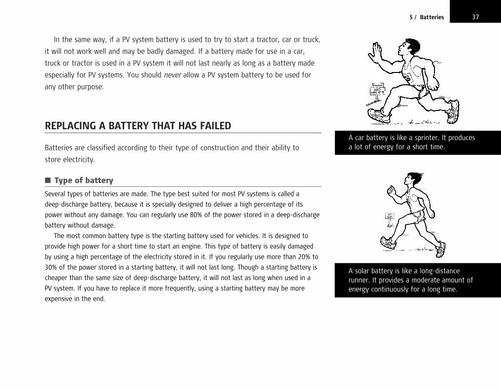
In the same way, if a PV system battery is used to try to start a tractor, car or truck,
it will not work well and may be badly damaged. If a battery made for use in a car,
truck or tractor is used in a PV system it will not last nearly as long as a battery made
especially for PV systems. You should never allow a PV system battery to be used for
any other purpose.
REPLACING A BATTERY THAT HAS FAILED
Batteries are classified according to their type of construction and their ability to
store electricity.
■ Type of battery
Several types of batteries are made. The type best suited for most PV systems is called a
deep-discharge battery, because it is specially designed to deliver a high percentage of its
power without any damage. You can regularly use 80% of the power stored in a deep-discharge
battery without damage.
The most common battery type is the starting battery used for vehicles. It is designed to
provide high power for a short time to start an engine. This type of battery is easily damaged
by using a high percentage of the electricity stored in it. If you regularly use more than 20% to
30% of the power stored in a starting battery, it will not last long. Though a starting battery is
cheaper than the same size of deep-discharge battery, it will not last as long when used in a
PV system. If you have to replace it more frequently, using a starting battery may be more
expensive in the end.
375 / Batteries
A solar battery is like a long-distancerunner. It provides a moderate amount ofenergy continuously for a long time.
A car battery is like a sprinter. It producesa lot of energy for a short time.
chapter5.qxd 11/8/03 12:00 PM Page 37

■ Ability to store electricity
Batteries are classed according to how much electricity they can store. The measure used
is the ampere-hour (Ah). If a battery delivers 1 A of current continuously for 100 hours
it has provided 100 Ah. If a battery delivers 10 A continuously for 10 hours, it has also
delivered 100 Ah. If 5 A is delivered continuously for 20 hours, that is 100 Ah too.
Ampere-hours are equal to the continuous current being taken from the battery times the
number of hours it is delivered. If a current of 7 A is delivered for 6 hours, that will be
6 × 7 = 42 Ah.
If a battery is rated at 100 Ah, it means that ideally it can be expected to deliver 1 A for
100 hours, or 10 A for 10 hours, 5 A for 20 hours or any combination of amperes and hours
that equal 100 when multiplied together. In fact, it is not that simple because a battery can
deliver more ampere-hours when it is discharged very slowly than when it is discharged quickly.
Just as when you work very fast, you will get tired sooner and not do as much as if you work
slowly and steadily. So if a battery can deliver 100 Ah when it is discharged quickly, it may be
able to deliver 150 Ah when it is discharged slowly. Therefore to find the real ampere-hour
capacity of a battery, you need to know how quickly it will be discharged. This is called the
discharge rate. It is often stated as the number of hours for full discharge. So a battery
may be rated as 50 Ah at a 10 hour discharge rate. Exactly the same battery may be rated
as 70 Ah at a 100 hour discharge rate. Manufacturers show this on their specification
sheets as C10 and C100 or as C/10 and C/100 rates. C10 means a battery capacity that
will discharge completely from full charge in 10 hours. C100 means a battery capacity that will
discharge completely from full charge in 100 hours. Be careful when comparing manufacturer’s
specifications for batteries.
When replacing a battery, the new one should never have a lower ampere-hour rating for
the same discharge rate than the one originally installed. If the battery is a deep-discharge
type, the replacement does not need to be higher in rating than the original battery.
Some manufacturers of solar batteries advertise the capacity of their batteries as C100 and
other manufacturers advertise C10 or C20. Because a battery can deliver more ampere-hours if
38 Solar Photovoltaic Systems Technical Training Manual
REPLACING BATTERIES
When you replace a battery, try to find thesame type and the same size of battery asoriginally installed.
If the original battery was a solar or deep-discharge type, you should not replace itwith a vehicle or starting-type battery.
If the original battery was an open-cell type,you should not replace it with a ‘maintenance-free’ type of battery.
If you must replace a solar or deep-dischargebattery with a starting battery, for longest lifethe new battery should have twice thecapacity of the original battery. Thus if theoriginal deep-discharge battery was 65 Ah, thenew battery should have a capacity of at least130 Ah.
If you must replace an open-cell battery with a maintenance-free battery, the newbattery should have a capacity half as muchagain as the original battery. Thus if theoriginal open-cell battery was 100 Ah, the newmaintenance-free battery should be at least150 Ah for longest life.
If you do not know the capacity of the originalbattery, or if the new battery does not have a capacity rating on it, you can compare thecapacity of the two by comparing their weight.The heavier the battery, the more lead is insideand the more capacity it is likely to have.
chapter5.qxd 11/8/03 12:00 PM Page 38

395 / Batteries
discharged slowly, the C100 rating will make a battery look bigger. The same battery that is
100 Ah at C100 may be rated as only 65 Ah at C10. Always compare batteries at the same
discharge rate. Most people use a C10 rate as a standard for comparison. Here we always
use a C10 rate for working out the size of a battery.
Starting-type (vehicle) batteries are not designed for PV systems but if a starting battery
has to be used, obtain one at least twice as big as the solar-type battery originally installed.
If the original battery with the PV system had a 105 Ah rating at C10 and you have to replace
it with a vehicle battery, the replacement should have a rated capacity of at least 210 Ah.
Even with the larger battery, it will not last as long as a proper deep-discharge type, but at
least it should last for several years.
If an open-cell solar battery is to be replaced with a maintenance-free solar battery,
the new battery should be half as large again as the old open-cell battery in order to
last a similar time. So if the original open-cell battery had a capacity of 100 Ah at C10,
a maintenance-free solar battery to replace it should have a capacity of at least 150 Ah at C10.
DIFFERENCE BETWEEN A BATTERY FULL OF ELECTRICITY (CHARGED) AND AN EMPTY ONE (DISCHARGED)
It is easy to check whether a water tank is full or empty. It is more difficult to tell if
a battery is full or empty of electricity as we cannot see electricity. A tester is used to
find out whether a battery is charged or not.
Two types of tester are used to check how much electricity a battery contains.
The most common type, called a hydrometer, checks the acid in the battery for
strength. The stronger the acid, the more electricity is stored in the battery.
A hydrometer is a glass tube with a special float in it. The battery acid is sucked up
into the tube by squeezing a bulb on top. The float then rises towards the top of the
A float gauge in a water tank shows theamount of water in the tank by how highit floats.
A hydrometer shows the level of charge ina battery by how high it floats.
chapter5.qxd 11/8/03 12:00 PM Page 39

liquid. Markings on the float show how strong the acid is. If the float rises high in
the liquid, then the battery is full of electricity. If it floats low, the battery is low.
If it rises part way, the battery is partly full. After testing, squeeze the bulb to return
the liquid to the cell.
The hydrometer measurement is like a float gauge on a water tank. In a water tank,
if the float is high, the water level is high. If it is low, the water level is also low.
In a battery, if the hydrometer float is high, the battery charge is high. If it floats
low, the charge level is low.
Another way to check the amount of electricity in a battery is to use a voltmeter
to measure the voltage (electrical pressure) of the battery. When a water tank is
full, the pressure is higher at the outlet tap than when the tank is low on water.
When a battery is full of electricity, the voltage is higher than when it is low
on electricity.
A battery rated at 12 V will in fact measure over 13 V when it is fully charged and
less than 11 V when the charge is getting low. A 12 V battery has very little charge left
in it if its voltage falls below 11 V. In normal use, a deep-discharge battery should not
be discharged to a voltage less than 11.5 V.
As the difference between the voltage of a low battery (11.5 V) and a full battery
(13.5 V) is only 2 V, a high-quality voltmeter must be used to read the level of charge
accurately.
Measuring the voltage level is the easiest way to check the charge in a battery
but accurate voltmeters are expensive and easily damaged. A voltmeter also gives a
different indication of battery charge than a hydrometer. For the most accurate checks
it is better to use both a hydrometer and a voltmeter. If they both agree on the level
of charge in the battery, the battery is probably all right. If the voltmeter shows a high
level of charge and the hydrometer shows a low level of charge, then the battery
may be damaged.
40 Solar Photovoltaic Systems Technical Training Manual
Water pressure is highest when the storagetank is full.
Electrical pressure (voltage) in a storagebattery is highest when the battery is fullycharged.
When a new battery is installed, let the solarsystem charge the battery for at least twosunny days before using any electricity.
chapter5.qxd 11/8/03 12:00 PM Page 40

INSTALLING A NEW BATTERY
The liquid (acid) used in storage batteries is called electrolyte. To install a new battery
that already has electrolyte in it, first make sure that the level is correct in all the
cells, then just connect the battery and allow it to charge from the solar panel for at
least two sunny days before turning on any lights or other appliances. If a new battery
is filled with electrolyte but the level in one or more of the cells is low, add only acid
(not water) before connecting the battery to the PV system. In all cases, fully charge
the battery before using it to operate any appliances.
If the new battery arrives with no liquid in the cells, the cells must be filled with
electrolyte. Because the acid may harm eyes, skin and clothes it is important to handle
it carefully.
Fill the battery slowly and be very careful not to spill any acid. You should fill each
cell so slowly that you can count to at least thirty in the time it takes to fill it. It is
best to put a little acid in one cell, then put some in another cell and rotate through all
the cells before adding more to the first cell. This will make sure that you are not
filling the cells too quickly.
Note that the battery becomes warm after it is filled. This is normal but it can get
too hot and be damaged if it is filled too quickly, so always fill slowly and carefully.
If the battery comes with filling instructions, follow them carefully. If no instructions
are provided, fill the cells so that the acid covers the plates in each cell but is below
the bottom of the fill opening.
A newly filled battery should be immediately connected to the PV system and
allowed to charge for at least two sunny days before any electricity is used. For the
battery to last a long time, never connect appliances to the battery until after it
has been fully charged by the solar panel.
415 / Batteries
IMPORTANT: If acid gets on your skin, eyesor clothes, wash it off immediately withlots of clean water.
The battery should be installed in a plasticor wooden box with holes near the top toallow air to reach the battery andexplosive gases to escape. Never use ametal box because the acid will corrodethe metal.
The first step in maintaining a battery is toclean it with a wet cloth. Use only freshwater and do not use soap. Rinse the clothafter use because some acid may remainfrom cleaning the battery top.
chapter5.qxd 11/8/03 12:00 PM Page 41

The battery should be installed in a plastic or wooden box with holes through the
sides near the top to allow air to reach the battery. Never use a metal box because
the acid will corrode the metal. Plastic is best because wood will also be damaged
by the acid, though less so than metal. If you use a wooden box, put a piece of plastic
under the battery to protect the wood.
The battery should be installed on a hard, level surface. It should not be placed
where small children can reach it because they may be hurt by the acid. Place the
battery where it is not likely to be knocked over accidentally.
The wires should be firmly attached using bolts. Never use spring clips or just wrap
the wire around the posts. After the connection is tightly made, paint the terminals
with thick oil or grease to prevent corrosion. Do not paint the oil or grease anywhere
except on the battery terminals and do not put oil or grease on the battery terminals
before the connection is made.
BATTERY MAINTENANCE
Three things must be done to maintain a PV system battery correctly.
■ Maintenance step 1
Keep the battery clean. If the top of the battery is dirty, corrosion will soon be a problem
and electricity will begin to leak from the battery connections through the dirt. To clean the
battery, use only fresh water and a rag. Do not use soap or salt water. Because a little acid
will probably be on the battery, be careful not to touch your eyes with hands or rags that
have touched the battery. Wash all rags and your hands in fresh water when you are finished.
Paint the terminals with thick oil or grease again after cleaning.
42 Solar Photovoltaic Systems Technical Training Manual
To prevent corrosion on the terminals and a high loss of charge through the batteryconnections, after assembly paint the surfacesof the battery terminals with heavy grease,petroleum jelly, or other material that keepsair and water off the terminals.
After a new battery is filled with acid, youshould never add more acid unless the batteryhas been knocked over and the acid spilledout. As long as no acid has spilled out, add only pure, fresh water to the cells.
Always keep a good supply of pure, cleanwater for filling batteries. Use distilled waterwhenever possible.
chapter5.qxd 11/8/03 12:00 PM Page 42

■ Maintenance step 2
Test each cell with the hydrometer. All the cells should measure about the same when tested
with the hydrometer. If one or more cells measure very differently from the others, the battery
is probably beginning to fail. A failing battery can still be used as long as the system is working,
but you should watch the battery very carefully to see if it gets worse.
You should keep a card near the battery and each time the battery is checked you should
write down the hydrometer readings, voltage readings, and the date. Then you can compare
the readings from earlier visits and you will usually be able to tell when a battery is gradually
failing.
Sometimes there will not be enough electrolyte in a battery cell to suck up into the
hydrometer to measure. In that case, add pure, clean, fresh water until the cell is filled to the
correct level. Wait at least one day before taking a reading with the hydrometer after filling
with water.
■ Maintenance step 3
Keep the battery cells full of electrolyte. The battery cells should be checked at least once
a month and special, high-purity water added if the liquid is below the correct level. After
the battery is filled with acid when new, you should never add more acid unless the battery
has been knocked over and the acid spilled out. As long as the acid has never spilled out
of the cells, add only pure, fresh water, never more acid. Many people think that adding more
acid will make a battery stronger. They are wrong, it will damage the battery.
The water used in the battery must be pure, clean and fresh or the battery life may be
shortened. It is always best to use distilled water. Never use water collected on a roof or metal
surface and never use bottled water unless it is distilled. If you cannot get distilled water, you
can use rainwater that has never touched anything but clean plastic or glass.
Here is a good way to collect rainwater for batteries:
➔ Find a glass or plastic container that has never been used to store diesel fuel, gasoline
(benzine), kerosene, cooking oil or other oily material.
➔ Clean the container carefully with fresh water and rinse well with more fresh water.
Do not use soap.
435 / Batteries
Take hydrometer readings regularly andalways write them down so that you cantell if cells that are low today are regularlylower than the others. This means that thecells need an equalizing charge (see page 45).
When distilled water is not available, if rainwater is collected on clean plasticand stored in a clean plastic or glasscontainer, it can be used for batteries.
chapter5.qxd 11/8/03 12:00 PM Page 43

➔ Drive three sticks into the ground in a place away from trees and the sea. The tops of
the sticks should be about 15 cm (6 inches) higher than the container you have
cleaned. The sticks should be spaced about 1 m (3 feet) apart. When it rains, stretch
a sheet of clean plastic across the tops of the sticks, tying the plastic tightly to the top
of one stick and loosely to the tops of the other two so that it sags between the two
sticks about 10 cm (4 inches). The plastic will form a trough where the rain will collect
and pour out at the lowest point where the container will be placed.
➔ Let the rain fall on the plastic for 10 to 15 minutes to clean it. Rinse the container with
rainwater too.
➔ Place the container on the ground under the lowest part of the plastic sheet. The rain will
be caught by the plastic sheet and directed into the container.
➔ When the rain stops or when the container is full, it should be capped with a plastic or
cork cover and stored inside to stop dirt getting into the water. A metal cap should not
be used. The pure water that has been collected should not be used for anything except
filling the cells in solar batteries. When properly stored, it will last for years.
Do not fill the battery cells so that the water reaches the top of the fill holes. If you do,
as the battery is charged, electrolyte will spill out and acid will spread over the top of the
battery. The electrolyte should always cover the lead plates you can see as you look into
the fill hole, but should not come up into the fill hole itself. There is usually a mark
on the side of the battery or an indicator in the fill hole that shows the correct level for
the electrolyte.
Battery caps must always be in place except when you are checking the battery. The caps
have a small hole to let the cell breathe. If that hole is plugged, the cell may be damaged.
If a cap is lost or broken and a proper replacement cap is not immediately available, use a small
piece of plastic to cover the hole. Remember never to plug the hole tightly because the cell
must have air to operate. Never use paper, wood, cork or metal to cover the fill holes,
only plastic or glass.
If water has to be added more than once each month to all the battery cells, the system
charge controller is probably not working properly. The controller should be replaced or
returned for adjustment or repair.
44 Solar Photovoltaic Systems Technical Training Manual
By keeping a record of hydrometer readings,you can tell if a cell begins to weaken and youcan give it an equalizing charge to repair it.
If water has to be added more than once a month to all the battery cells, the systemcharge controller is probably not operatingproperly. It should be replaced or returned foradjustment or repair.
Do not smoke near batteries because explosivegases may be present in the cells.
chapter5.qxd 11/8/03 12:00 PM Page 44

If water has to be added often to one or two cells but not the rest of the cells, the battery
is failing and it will probably have to be replaced soon.
EQUALIZATION
When a battery begins to show different readings in different cells, it is beginning to
fail. Sometimes the battery can be repaired by deliberate overcharging. This is called an
equalizing charge.
To equalize the cells in a battery, you have to give them a slow, controlled
overcharge. Because the charge controller is intended to prevent overcharge,
it must be bypassed and the panels connected directly to the battery.
Starting with a charged battery, two sunny days should be enough for an equalizing
charge to work. You can tell when equalization is taking place because many small
bubbles will form in the cells, the terminal voltage will be above 15 V and the battery
may be unusually warm. If the days you have chosen are not completely sunny, several
days may be needed. During this time, lights and other electrical appliances should not
be used.
Even if cells do not appear unbalanced, equalizing every six months is a good idea.
The battery will lose water quickly during equalization. Always refill the cells to the
correct electrolyte level every day while the battery is equalizing.
SAFETY NEAR BATTERIES
Although the voltage of a battery is not high enough to cause harm, if a piece of
metal is placed across the terminals of a charged battery, there is enough power in
the battery to produce a large, hot spark that could start a fire.
455 / Batteries
CELL EQUALIZATION
When a battery is new, all the cells shouldhave about the same capacity to be charged.As the battery ages, some of the cells mayweaken. The weak cell usually gives aconsistently lower hydrometer reading thanthe other cells in the battery.
If this problem continues for several months,the cell is likely to become permanentlyweaker than the rest.
If the problem is caught early and thebattery is given an equalizing charge, thenthe weak cell may recover its capacity andnot suffer permanent damage.
Some manufacturers recommend anequalizing charge at least once every sixmonths. In practice, an equalizing charge isusually given only when there is evidence of one or more cells becoming weaker thanthe rest.
Battery acid in the eyes can causeblindness unless washed out quickly andthoroughly.
chapter5.qxd 11/8/03 12:00 PM Page 45

The acid in a battery is not strong enough to cause immediate burns to the skin and
no harm will probably be done if it is washed off immediately. To remove the acid,
lots of water must be used for washing. Fresh water is best, though sea water will do.
But be very careful not to get sea water into a battery or it will be ruined. Acid in the
eyes can cause damage and sometimes blindness. Do not look straight down into the
fill hole while acid or water is being added. After handling, filling or testing a battery,
be careful not to touch your eyes before washing your hands. If any acid gets into your
eyes, wash them with lots of water by immersing your head in a bucket of water or,
if possible, dunking in a pool.
When the battery is connected, it sometimes produces a gas that will explode
if a flame is near. Never smoke, light matches, or use an open flame lantern near
a battery, particularly when checking or filling the cells.
46 Solar Photovoltaic Systems Technical Training Manual
Never lay anything metal on top of a batterybecause shorted battery terminals can start a fire.
chapter5.qxd 11/8/03 12:00 PM Page 46

INTRODUCTION
If a water system is installed using pipes that are too small, water pressure will be lost
in the pipes. By the time the water reaches the user, the pressure may be so low that
not enough water comes out to be useful. The reason for the loss of pressure is
that the small pipe has too high a resistance and some of the pressure is used just
keeping the water flowing in the pipe.
In an electrical system, if the wires are too small, electrical pressure (voltage) is lost
and appliances may not get enough electricity to work properly. The reason for the loss
of voltage is that the small wires have too high a resistance and some of the voltage is
used just keeping the electricity flowing in the wires.
Wiring that is too small is a common reason for poor performance of solar
PV systems. It is important to understand that the wiring used for a 12 V or 24 V solar
installation must be much larger than wire used to carry the same amount of power at
240 V from a city electrical system.
47
6Wiring
Small pipes lose more water pressure thanlarger pipes. Small wires lose more voltagethan larger wires.
Wire connecting appliances in a solarinstallation must be larger than wire used for appliances with the same wattrequirement using 240 V ac power.
chapter6.qxd 11/8/03 12:06 PM Page 47

RELATION OF SIZE TO POWER LOSS
Pipe size. Water flows easily through a large pipe but not through a small pipe.
The smaller the pipe, the more difficult it is to force water through it. To make water
flow through a pipe, there must be force behind it. That force is the water pressure.
To move a certain amount of water each day through a large pipe takes less
pressure than to move it through a small pipe. As the power needed to move the
water is the pressure times the flow rate, a small pipe needs more power than a large
pipe to move the same amount of water through the pipe in a day. Power costs
money. Larger pipes can be installed to save power, but large pipes cost more than
small ones. When designing a water system, the designer has to compare the cost of
larger pipes with the cost of the extra power to force water through smaller
pipes.
Wire size. The same problem arises with solar PV systems. The smaller the wire,
the more electrical pressure (volts) are needed to force a certain current (amperes)
through the wire. To get this higher voltage, more batteries and panels must be
installed, usually at extra cost. If you use very large wires, the voltage needed to push
the electricity through the wires is low, but the cost of the wires is much higher.
The best size of wire will compromise between the cost of larger wire with low voltage
losses and the cost of the extra panels and batteries to overcome the losses from
cheaper, smaller wire.
RELATION OF LENGTH TO POWER LOSS
Pipe length. The longer a pipe, the more difficult it is to force water through it.
To move a certain amount of water each day through a short pipe takes less pressure
than moving the water through a long pipe of the same size. As the power needed to
48 Solar Photovoltaic Systems Technical Training Manual
At the same pressure, more water flowsthrough a large pipe than a small one. If apipe is too small not enough water will flow.
At the same voltage, more electricity flowsthrough a large wire than a small one. If a wire is too small not enough electricity will flow.
chapter6.qxd 11/8/03 12:06 PM Page 48

move the water is the pressure times the flow rate, using a long pipe will require more
power to move the same amount of water than using a short one. Power costs money.
To save power, pipes should be as short as possible.
Wire length. The same problem exists with solar PV systems. More electrical pressure
(voltage) is needed to force a certain current (amperes) through a long wire than
a short one of the same size. To get this increased voltage, more batteries and panels
must be installed at extra cost. To save cost, wires should be kept as short as possible.
Short wires save on wire cost and cause less power loss.
VOLTAGE DROPS FROM WIRING
The reason for the power loss in wire is its resistance (ohms). It takes force (volts) to
push electricity through a wire and the more resistance the wire has, the more force
must be used. The voltage needed to push electricity through a wire is called the
voltage drop of the wire. It is called voltage drop because the voltage at the appliance
end of the wire is lower than the voltage at the battery end by the amount needed to
push the electricity through the wire. The wire resistance causes a drop in voltage.
It takes more force to push a lot of electricity through a wire than to push a small
amount. Therefore, the voltage drop in a wire increases as the current (amperes)
increases. The exact voltage drop of the wire equals the amperes being pushed through
the wire times the wire resistance in ohms.
An appliance requires a certain voltage and a certain number of amperes to work
properly. The appliance determines the number of amperes that must flow in the wire
connecting it to the battery. If the appliance cannot get enough amperes because the
voltage is too low, it will not work properly and may be damaged.
496 / Wiring
1 m of copper wire that is 1 mm2 in size hasa resistance of about 0.02 �. The totalresistance of a wire can therefore becalculated by the formula:
ohms = 0.02 × metres ÷ size in mm2
As volts = amperes × ohms, the voltage dropin a wire can be calculated by the formula:
volts lost = amperes × (0.02 × metres ÷ mm2)
The length of wire in a circuit is double the distance between the end points, so the number of metres of wire is twice the distance that the wire runs.
This is the formula for calculating wire sizewhich gives a 0.5 V drop for any distance ofwire run and current:
mm2 = 0.08 × wire run in metres
× amperes
Pipes that are too long lose too muchpressure. Wires that are too long lose toomuch voltage.
chapter6.qxd 11/8/03 12:06 PM Page 49

Wire length and voltage drop. Because wire resistance increases as wire length
increases, the shorter the wire the better. If the voltage drop between the battery and
an appliance is 2 V with a 10 m wire, shortening the wire to 5 m will cut the voltage
drop in half to only 1 V. Not only does a shorter wire make more volts available to the
appliance, it also cuts the cost of the wire, so a double advantage is gained. This leads
to Wiring Rule 1: Wires should be as short as is practical.
Wire size and voltage drop. Because wire resistance decreases as wire size increases,
the voltage drop in the wires goes down as wire size goes up. Doubling the size of the
wire cuts the wire voltage loss in half. But doubling the wire size will increase the cost
of the wire. One solution is to allow the wire to lose some voltage but not so much as
to cause problems with the appliances. This leads to Wiring Rule 2: The voltage drop
in a 12 V system should not be greater than 0.5 V. In a 24 V system it should not be
greater than 1 V.
TYPES OF WIRE
There are several different types of wire. It is important to use the correct type of wire
when installing a solar PV system.
■ Conductor type
The metal core that carries the electricity is called the conductor. Although wires are sometimes
made with aluminium conductors, wire used for home and small commercial applications is
always copper. Even if aluminium wire is available at no cost, never use it in house wiring
because unless it is correctly installed with special connectors, which are difficult to obtain,
it will not work well or last long.
50 Solar Photovoltaic Systems Technical Training Manual
The three things that determine the loss of voltage in a wire are:
1) the number of amperes flowing in the wire
2) the wire size (in mm2)
3) the wire length (in metres).
WIRING RULE 1
Never use wires thatare longer than youreally need.
WIRING RULE 2
The maximum voltage drop for 12 V solarsystem wiring should not exceed 0.5 V. For a 24 V system, it should not exceed 1.0 V.
chapter6.qxd 11/8/03 12:06 PM Page 50

516 / Wiring
For house wiring, solid copper wire is often used. It consists of a single solid copper
conductor inside an insulating sleeve. Solid wire is usually the cheapest but it is inflexible and if
bent back and forth enough times it will break.
Wire is often made up of many small strands of wires all bunched together inside the
insulating sleeve. This is called stranded wire. Though each strand is very small, enough strands
are bunched together to make the total wire area equal to that of a solid wire. If each
strand is, for example, 0.1 mm2 in size, then 25 strands will be used in a 2.5 mm2 wire.
The main advantage of stranded wire is its flexibility. The more strands in the conductor,
the more flexible the wire. Most appliance power cords have a stranded wire. Very large
electrical wires are also stranded because a single solid wire would be too difficult to bend.
Electrically, there is no difference between equal sizes of stranded and solid wire.
Solid wire is cheaper and good for permanent installations. Stranded wire is usually best for
any application where the wire is not permanently fixed in place.
■ Insulation
Insulation on a wire is mainly intended to prevent accidental electrical connections so that no
electricity is lost through leakage to the material surrounding the wire. Insulation is also for
safety. At the low voltages of a PV system, an electric shock is not likely but burns or a house
fire can be caused if poorly insulated wires touch and cause a short circuit.
Another use of insulation in some wires is to combine several conductors into one unit.
All electrical circuits require one wire going to the appliance from the power source and another
wire returning. So it is common for house wiring to include two separate conductors combined
into one insulating sheath. This is called two-conductor cable. Three conductors or more can
also be combined into one insulating sheath. For PV systems two conductors are usually
enough. Multiple-conductor cable has two layers of insulation. The outside insulation holds
the different wires together and the inside insulation forms a layer around each individual
wire. For house wiring, two-conductor cable is more convenient to install than two
single-conductor wires.
Some wire is made from many small wiresbunched together in an insulating sleeve.This is called stranded wire and is usedwhere flexibility is needed. Other wire ismade from one single solid conductor. This wire is cheaper but may break if benttoo many times in the same place.
A cable has more than one wire inside.
WIRING RULE 3
Always use the right kind of wire for the job.Buried wire must have insulation rated forunderground. Wire exposed to sunlight musthave exterior grade insulation. Wire withinterior grade insulation should not be buriednor exposed to the sun for long.
Many small copper wires (strands)
One big solidcopper wire
Copper wires
Cablesheath
Insulation
chapter6.qxd 11/8/03 12:06 PM Page 51

Insulation also protects the wires from damage. Heavy insulation, resistant to wear,
is used for wiring that will be moved often or may be stepped on or run over by vehicles.
Special insulation is needed for wires that will be buried or exposed to sunlight and
the weather.
When buying wire, make sure that the insulation is right for the job. If the wire will be
exposed to the weather, as when it is used for connecting solar panels, the insulation must
be designed for exposure to sunlight and rain. Standard indoor house wiring will harden and
crack open if exposed to sunlight for long periods. If the wire will be buried, the insulation
must be designed to resist the fungus and moisture always present in the ground. Standard
indoor house wiring will be ruined by long burial. This leads to Wiring Rule 3: Always use the
right kind of wire for the job.
CHOOSING THE CORRECT SIZE OF WIRE
At the end of this chapter are four tables. These tables can be used to find a suitable
size of wire to connect panels or appliances to batteries.
Two of the tables are for use with 12 V systems and two are for 24 V systems.
Before using a table, check that it is the right one for the voltage in your system.
Looking at the tables, three things must be known in order to choose the correct
wire size:
➔ the voltage of the PV system battery (12 V or 24 V)
➔ the distance in metres along the path of the wire
➔ the number of amperes that must flow through the wire to operate the appliance
connected to it.
Battery voltage. The battery voltage for most solar PV systems will be either 12 V or
24 V. If the voltage is not 12 V or 24 V these tables should not be used.
52 Solar Photovoltaic Systems Technical Training Manual
To deliver the same power(in watts) wires in 24 Vsystems need only be one-fourth of the size (inmm2) of those used with12 V systems.
To calculate the exact wire size needed in a12 V appliance circuit so that no more than a 0.5 V drop occurs, you can use the formula:
mm2 = 0.08 × amperes × metres
where mm2 is the size of the wire, amperes isthe number of amperes which will flowthrough the wire, and metres is the length ofthe wire path between the battery and theappliance.
For example, for a simple lighting circuit with a lamp that needs 4 A to operate, located 5 mfrom the battery, you would have:
Note that you must use the length of theactual path the wire will follow.
So the calculation is:
mm2 = 0.08 × 4 A × 5 m = 1.6
and if there is to be no more than a 0.5 V lossin the wire, a wire size of at least 1.6 mm2 isrequired.
BatteryLight
5 metres distancealong the wire run (4 amperes)
chapter6.qxd 11/8/03 12:06 PM Page 52

Distance along the path of the wire. The length must be measured along the actual
path the wire follows all the way to the battery.
To use the wire tables, first select the 12 V or 24 V table that fits your system.
The exact size tables are mainly used for large systems requiring wires larger
than 4 mm2. They should also be used when one wiring circuit feeds more than
one appliance.
■ Appliance to battery
It is very easy to use the wire sizing tables when a single appliance is connected by a wire to
the battery. First find the ampere rating or watt rating of the appliance. This is usually shown
on the label although sometimes it can only be found on specification sheets packed with
the appliance. The amperes used by an appliance can also be measured while it is in use
with an ammeter.
Starting at the top left of the table, move down the watts or amperes column until you
find the first row with the number of watts or amperes equal to, or higher than, the appliance
rating.
Next, measure or closely estimate the total distance the wire must run between the battery
and the appliance. Make sure that you allow for any extra wire that goes to switches, and the
extra length needed to go around doors, windows or to make other detours.
Then, in the table, go across the row with the correct watt/ampere value until you reach
a column for a wire length equal to, or longer than, the wire length you need.
Read the wire size in mm2 in the box where the wire length column and the watt/ampere
row meet. If you are using an exact size table, then the exact number of mm2 that will work is
given. If you are using the standard wire table, then the standard metric wire size that fits the
application is shown. You can use the wire size shown or a larger size. Never use a smaller size.
536 / Wiring
Distance is always measured along theactual path the wire follows in theinstallation. Side branches to switches orextra wire needed to go around doors andwindows must be included in the totaldistance between the battery and theappliance. Even though the wire you areconnecting may go to a controller insteadof all the way to the battery, the distancefor working out wire size must bemeasured all the way from the appliance to the battery.
To carry the same amperes withoutincreasing the voltage drop, wires that aretwice as long must be twice the size in mm2.
chapter6.qxd 11/8/03 12:06 PM Page 53

■ More than one appliance connected to one wire
It is not always the case that only one appliance is connected to a wire. Suppose you have
three appliances connected to one wire. Suppose that the first appliance is a television that
needs 60 W of power and it is 2 m away from a 12 V battery. The second appliance is a fan
that needs 24 W and is 4 m from the battery. The last appliance is a light that needs 13 W and
is 7 m from the battery.
In this example, the wire is connected in three sections. Battery to appliance one (television),
appliance one to appliance two (television to fan) and appliance two to appliance three (fan to
light). The first section (battery to television) carries not only the power for the television but
also electricity that will flow on to the fan and light. The second section (television to fan) does
not carry power to the television but does carry the power for both the fan and the light.
The third section (fan to light) carries no power to either the television or the fan, only power
for the light.
Step one is to use the table to find the exact wire size needed for each appliance if each
appliance was connected by itself. For the television that is 2 m from the battery and uses 60 W,
a wire size of 0.80 mm2 is needed. For the fan 4 m from the battery and using 24 W, a wire of
0.64 mm2 is needed. For the 13 W light 7 m from the battery, a wire of 0.61 mm2 is needed.
Step two is to combine the multiple wire sizes into one. The wire from the battery to the
television will have to be large enough to carry power to all three appliances. It will need to be
0.80 plus 0.64 plus 0.61 mm2 in size, or 2.05 mm2. The section of wire between the television
and the fan will be carrying the power needed by the fan and the light so the minimum wire
size needed in this section will be 0.64 + 0.61 = 1.25 mm2. Finally, the section between the fan
and the light will only be carrying power for the light, so that wire must not be smaller than
0.61 mm2. While it is technically correct to connect the three appliances using the three
different wire sizes, the largest of the three sizes is usually used for all the connections.
In this case, the smallest acceptable size would be 2.5 mm2 wire.
54 Solar Photovoltaic Systems Technical Training Manual
The four wire sizing tables at the end of this chapter are in two groups, one for 12 Vsystems and the other for 24 V systems.
In each voltage group, the first table gives theexact minimum size of wire that can be usedfor different lengths of wire run and forcarrying different numbers of amperes. The main use of this table is to calculate theminimum wire size needed when more than oneappliance is connected at different points alonga wire. It is also useful when the wire to beused is measured in units that are not mm2 butcan be converted from those given in the table(for example American Wire Gauge or AWG).
The second table in each group gives thestandard metric wire size for connecting oneappliance of a given wattage at a givendistance from the battery (wire length).
As well as for connecting appliances to thebattery, both tables can also be used to selectthe correct wire size for connecting PV panelsto the battery.
chapter6.qxd 11/8/03 12:06 PM Page 54

This method can be used for any number of appliances by dividing the circuit into the same
number of sections as there are appliances.
Although you can use the exact wire sizes from the table, you can also use any larger wire.
If a larger wire is used, the actual power loss is less so there will be an improvement in the
operation of the PV system.
The two most common metric wire sizes are 1.5 mm2 and 2.5 mm2. The difference in cost
between the two wire sizes is not large compared with the overall cost of the PV system, but
the losses in the smaller wire are much higher. For the best performance, use the 2.5 mm2 size
even if a smaller wire is given in the table. This leads to Wiring Rule 4: Do not use wire smaller
than 2.5 mm2 in PV system wiring.
Note that when you double the distance that the wire must run, you have to double the size
of the wire to keep the voltage loss the same. This means that you can use the table for longer
wire than listed. If you need to know the size of wire to run for 30 m, you can look in the table
for the size of wire to run for 15 m and double the size. In the same way, you can find wire
sizes for larger amperes than given in the table. Doubling the amperes for the same wire
run means that you will need double the wire size to keep the losses the same. So if you want
to know the wire size for a 50 A load, look in the 25 A row of the table and double the wire
size shown.
■ Appliances with motors
The watt or ampere rating on an appliance shows its electricity use while in normal, continuous
operation. For example, a refrigerator may show a power requirement of 60 W at 12 V.
This means when it is running continuously, it will need to receive 5 A of current from the
battery. Electric motors, however, require extra current to start. When an electric motor is first
turned on it may require several times the amperes it uses when running. The voltage drop in
the wire increases as the amperes through the wire increases. Therefore, a motor that is
starting and drawing extra amperes from the battery may cause such a large voltage drop in the
556 / Wiring 55
WIRING RULE 4
Do not use wire smaller than2.5 mm2 or 12 AWG in anyinstallation.
WIRING RULE 5
Wires from the battery to anyappliance with a motor (refrigerator,pump, washing machine, etc.) mustbe able to carry currents that are atleast double the usual amperesneeded. When using the tables forappliances with a motor, enter thetable at the row with twice the wattor ampere rating.
More than one appliance on a wire run.
Light -13 W7 metres to Battery
Fan24 W
4 metres to Battery
Television 60 W
2 metres to Battery
Battery
chapter6.qxd 11/8/03 12:06 PM Page 55

wire that it can cause problems with the appliance. This is particularly true when the battery is
partially discharged and its voltage low. To prevent this problem, wires running to appliances
with motors (refrigerators, washers and pumps, for example) should be sized for at least twice
as many watts or amperes as the appliance normally requires when running.
This leads to Wiring Rule 5: Wires from the battery to any appliance with a motor have to
carry currents that are at least double the usual amperes needed.
An exception to this rule is the wire running to electric fans. Fans do not require the extra
starting current and therefore do not need the oversized wire.
If the table shows a wire size larger than is available, several smaller wires can be combined
into one large one. So if the table shows 10 mm2 wire, four 2.5 mm2 wires can be run together
from the battery to the appliance.
■ Panel to battery connections
Problems of voltage drop can occur in the wires connecting solar panels to batteries.
The number of amperes that the wire must carry is not constant. It changes with the amount
of charge in the battery and the brightness of the sun. The wire size should be large enough
to pass the maximum amperes that the panels can produce. The maximum panel amperes is
often printed on the panel or in the panel specifications sheet as the Isc of the panel. If the
actual maximum panel amperes is not known, remember that watts equals volts times amperes.
So the panel peak amperes will be its peak watts divided by its voltage. As almost all solar
panels are designed to charge 12 V batteries, if you divide the peak watts by 12, you will
usually get a reasonable estimate of the peak amperes. Thus a 72 Wp panel (peak watt rating
as shown in the panel specification) could be expected to provide a maximum ampere output
of 72 W divided by 12 V, or 6 A.
For panel wiring you can use either the exact size table or the standard size table. For small
systems, the standard size table is usually best. But for large systems that require large wires,
the exact size table is more accurate.
56 Solar Photovoltaic Systems Technical Training Manual
Example 1
Your panels are rated as 110 Wp. You shouldassume the maximum amperes to be 9.2 A:
110 divided by 12 is about 9.2 A.
The amperes from solar panels change with the amount of energy from the sun and the Wp (Watt peak) rating of the panels.The loss in the wires increases as the amperesincrease. So to make sure that the actual wirelosses are acceptable, you should calculate thewire size based on the maximum number ofamperes that will come from the panels. As the Wp of the panels is known and almostall panels made today are designed for 12 V,you can estimate the maximum amperes from apanel by remembering that watts = volts ×amperes. So amperes must = watts ÷ volts. To estimate the amperes from a panel, divide the Wp by 12 V.
chapter6.qxd 11/8/03 12:06 PM Page 56

If the table gives a wire size larger than is available, several smaller wires can be combined
into one large one. So if the table gives 10 mm2 wire, four 2.5 mm2 wires can be run together
from the panels to the battery.
Note that when you double the distance that the wire must run, you have to double the size
of the wire to keep the voltage loss the same. This means that you can use the table for longer
wire than listed. If you need to know the size of wire to run for 30 m, you can look in the table
for the size of wire to run for 15 m and double the size.
■ Using the tables for non-European wire
While wire sizes measured in mm2 and wire lengths measured in metres are the most common
around the world, other wire size and length systems exist. To use the tables with these
measurement systems, first convert wire length to metres and look up the wire size in mm2
from the tables. To find the wire size in a special measuring system, a conversion table between
mm2 and the wire gauging scheme must be used. For example, in the United States, the
measure of length is the foot. To convert feet to metres, divide by 3.28. The wire size
system is called American Wire Gauge (AWG) and a table converting AWG to mm2 is given
on page 60.
CONNECTING WIRES
Connections in a PV system have to be very good because the electrical pressure
(voltage) available to push the electricity through the connection is low. In a regular
ac system, the voltage is 10 to 20 times higher than in a solar system. So wiring
connections that work well for regular ac systems may not work well for a solar
system. Connecting wires by twisting them together may work for a short time,
but the twisting gradually loosens and corrodes and, after a while, the connection
will have a high loss and cause problems.
576 / Wiring 57
Two important rules for connecting wires in a solar system:
1) Always use a screw-type connector.
2) Always tighten the screws firmly.
Example 2
A 24 V solar system uses 14 panels to power a health centre. The 42 Wp panels aremounted on the roof and the wireconnecting the panels to the battery will be12 m long. Only 2.5 mm2 wire is available foruse. Using the 24 V wire table, what wire sizeis needed? How would the panels be wired?
Select the 24 V exact size table. The total Wpwill be 14 × 42 = 588 Wp. Go down thewatts column to 600 W. Go across that rowto 12 m distance. You will see that theminimum wire size is 12 mm2.
Five 2.5 mm2 wires will have to be groupedtogether to provide a large enough wire tomeet the needs of the system.
As there will be seven pairs of panels in thearray, a reasonable wiring solution would beto use one 2.5 mm2 cable per pair of panels.This would provide a total wire size of 7 × 2.5= 17.5 mm2 and a very low voltage drop.
chapter6.qxd 11/8/03 12:06 PM Page 57

In regular ac systems, wires are often joined together by placing the two wires side
by side then screwing a ‘wire nut’ on to the wires. The wire nut does keep the wires
tightly together but corrosion can still be a long-term problem, especially in the tropics.
So wire nuts should not be used for PV system connections.
Soldered connections or crimped connections can be used if done properly, but it is
often difficult to find the right tools to make a good connection. Making proper
crimped connections also takes special training and experience. So it is usually best to
avoid soldered and crimped connections.
For solar installations, the only reliable way to connect wires is by using
a screw-type connector. The screw can be tightened to the point where corrosion
cannot occur and the connection will remain good. Also, it is easy to clean screw-type
connectors, so even if corrosion occurs it can be removed without much difficulty.
BATTERY CONNECTIONS
The connections to the battery are especially important as all the energy for
charging the battery and all the energy for operating the appliances goes
through the connections. Battery connections should always be of a screw type.
Never use spring clips or wrap the wire around the terminals in order to make the
connections. The best connections are made with screws that go through the battery
terminal. The compression connectors usually used on vehicle batteries do not work
well in the long term. They will corrode and will need cleaning every six months
or so if electricity losses are to be kept low. When you have to use a vehicle battery,
it is better to drill a hole through the terminal and use a bolt and nut to connect the
wire than to use a compression connector as used for vehicles.
58 Solar Photovoltaic Systems Technical Training Manual
Never twist wires together for a connection.
Wire nuts will not provide a goodconnection.
chapter6.qxd 11/8/03 12:06 PM Page 58

PANEL CONNECTIONS
The connections to the solar panel are also very important. Almost all solar panels have
a screw-type connector that provides a good connection. However, the screws often
gradually loosen over time and it is important to clean and tighten the panel
connections at least once a year if losses are to be kept low. Avoid using panels that
do not have screw connections.
WIRE TABLES
■ Standard wire tables
To simplify the calculation of wire size for circuits that only include the battery and one
appliance or the battery and the panels, tables for 12 V and 24 V systems are provided that
show the standard wire size to use.
Enter the table with either the amperes or watts of your appliance. Go down the ampere or
watts column until you reach either the exact number or the number just greater than the Wp
of the panels or the watts load for the appliance. Go across that row until you reach the
column that shows the wire length in metres between the battery and the panel or the battery
and the appliance you wish to connect. The number in that box is the size of wire in mm2 that
you will need to install.
■ Exact size tables
The 12 V and 24 V exact size tables give the exact wire size in mm2 that is the minimum size to
use. The value is obtained in the same way as the other tables. Go down the watts or amperes
column to the exact value or the closest value above it and across to the column that shows the
596 / Wiring
Battery connections shouldnever be made with springclips. Use only screw-typeconnectors.
Battery connections shouldnever have wires wrappedaround the post. Use onlyscrew-type connectors.
Community buildings usually have manylights. It is best to run separate wires foreach light and provide a switch for eachlight. Having many lights on one switchmay not work well. Also, to save thebattery it is better to turn on only thoselights that are really needed. You cannotdo that if all lights are on a single switch.
chapter6.qxd 11/8/03 12:06 PM Page 59

wire length in metres. This gives the exact minimum wire size needed. This value is important
for calculating the correct wire size to use when several appliances are connected to the same
wiring circuit. These tables are also useful when very large wire sizes are needed and you have
to join several wires together.
■ Wiring motors
Always remember to double the wire size shown in the tables if you are connecting
an appliance with a motor that starts under load, such as a refrigerator, freezer,
washer or pump.
60 Solar Photovoltaic Systems Technical Training Manual
American Wire Gauge
metric (mm2) equivalents
4 AWG = 21.1 mm2
6 AWG = 13.4 mm2
8 AWG = 8.41 mm2
10 AWG = 5.28 mm2
12 AWG = 3.32 mm2
14 AWG = 2.09 mm2
16 AWG = 1.32 mm2
For 12 V solar installations, the smallest wirethat should be used is 12 AWG for connectingappliances and 10 AWG for connecting panels.
chapter6.qxd 11/8/03 12:06 PM Page 60

12 V exact size table — for sizing wire to multiple appliancesor for connecting solar panels
Applianceload or Distance between battery and appliance (m)
panel Wp
1 2 3 4 5 6 7 8 9 10 11 12 13 14 15
Wp Exact wire size for no more than a 0.5 V voltage drop (mm2)or W A
6 0.5 0.04 0.08 0.12 0.16 0.20 0.24 0.28 0.32 0.36 0.40 0.44 0.48 0.52 0.56 0.6010 0.8 0.07 0.13 0.20 0.27 0.33 0.40 0.47 0.53 0.60 0.67 0.73 0.80 0.87 0.93 1.0012 1.0 0.08 0.16 0.24 0.32 0.40 0.48 0.56 0.64 0.72 0.80 0.88 0.96 1.04 1.12 1.2013 1.1 0.09 0.17 0.26 0.35 0.43 0.52 0.61 0.69 0.78 0.87 0.95 1.04 1.13 1.21 1.3015 1.3 0.10 0.20 0.30 0.40 0.50 0.60 0.70 0.80 0.90 1.00 1.10 1.20 1.30 1.40 1.5018 1.5 0.12 0.24 0.36 0.48 0.60 0.72 0.84 0.96 1.08 1.20 1.32 1.44 1.56 1.68 1.8020 1.7 0.13 0.27 0.40 0.53 0.67 0.80 0.93 1.07 1.20 1.33 1.47 1.60 1.73 1.87 2.0022 1.8 0.15 0.29 0.44 0.59 0.73 0.88 1.03 1.17 1.32 1.47 1.61 1.76 1.91 2.05 2.2024 2.0 0.16 0.32 0.48 0.64 0.80 0.96 1.12 1.28 1.44 1.60 1.76 1.92 2.08 2.24 2.4028 2.3 0.19 0.37 0.56 0.75 0.93 1.12 1.31 1.49 1.68 1.87 2.05 2.24 2.43 2.61 2.8030 2.5 0.20 0.40 0.60 0.80 1.00 1.20 1.40 1.60 1.80 2.00 2.20 2.40 2.60 2.80 3.0032 2.7 0.21 0.43 0.64 0.85 1.07 1.28 1.49 1.71 1.92 2.13 2.35 2.56 2.77 2.99 3.2034 2.8 0.23 0.45 0.68 0.91 1.13 1.36 1.59 1.81 2.04 2.27 2.49 2.72 2.95 3.17 3.4036 3.0 0.24 0.48 0.72 0.96 1.20 1.44 1.68 1.92 2.16 2.40 2.64 2.88 3.12 3.36 3.6038 3.2 0.25 0.51 0.76 1.01 1.27 1.52 1.77 2.03 2.28 2.53 2.79 3.04 3.29 3.55 3.8040 3.3 0.27 0.53 0.80 1.07 1.33 1.60 1.87 2.13 2.40 2.67 2.93 3.20 3.47 3.73 4.0045 3.8 0.30 0.60 0.90 1.20 1.50 1.80 2.10 2.40 2.70 3.00 3.30 3.60 3.90 4.20 4.5050 4.2 0.33 0.67 1.00 1.33 1.67 2.00 2.33 2.67 3.00 3.33 3.67 4.00 4.33 4.67 5.0055 4.6 0.37 0.73 1.10 1.47 1.83 2.20 2.57 2.93 3.30 3.67 4.03 4.40 4.77 5.13 5.5060 5.0 0.40 0.80 1.20 1.60 2.00 2.40 2.80 3.20 3.60 4.00 4.40 4.80 5.20 5.60 6.0065 5.4 0.43 0.87 1.30 1.73 2.17 2.60 3.03 3.47 3.90 4.33 4.77 5.20 5.63 6.07 6.5070 5.8 0.47 0.93 1.40 1.87 2.33 2.80 3.27 3.73 4.20 4.67 5.13 5.60 6.07 6.53 7.0075 6.3 0.50 1.00 1.50 2.00 2.50 3.00 3.50 4.00 4.50 5.00 5.50 6.00 6.50 7.00 7.5080 6.7 0.53 1.07 1.60 2.13 2.67 3.20 3.73 4.27 4.80 5.33 5.87 6.40 6.93 7.47 8.0085 7.1 0.57 1.13 1.70 2.27 2.83 3.40 3.97 4.53 5.10 5.67 6.23 6.80 7.37 7.93 8.5090 7.5 0.60 1.20 1.80 2.40 3.00 3.60 4.20 4.80 5.40 6.00 6.60 7.20 7.80 8.40 9.00
100 8.3 0.67 1.33 2.00 2.67 3.33 4.00 4.67 5.33 6.00 6.67 7.33 8.00 8.67 9.33 10.00110 9.2 0.73 1.47 2.20 2.93 3.67 4.40 5.13 5.87 6.60 7.33 8.07 8.80 9.53 10.27 11.00120 10.0 0.80 1.60 2.40 3.20 4.00 4.80 5.60 6.40 7.20 8.00 8.80 9.60 10.40 11.20 12.00130 10.8 0.87 1.73 2.60 3.47 4.33 5.20 6.07 6.93 7.80 8.67 9.53 10.40 11.27 12.13 13.00140 11.7 0.93 1.87 2.80 3.73 4.67 5.60 6.53 7.47 8.40 9.33 10.27 11.20 12.13 13.07 14.00150 12.5 1.00 2.00 3.00 4.00 5.00 6.00 7.00 8.00 9.00 10.00 11.00 12.00 13.00 14.00 15.00160 13.3 1.07 2.13 3.20 4.27 5.33 6.40 7.47 8.53 9.60 10.67 11.73 12.80 13.87 14.93 16.00170 14.2 1.13 2.27 3.40 4.53 5.67 6.80 7.93 9.07 10.20 11.33 12.47 13.60 14.73 15.87 17.00180 15.0 1.20 2.40 3.60 4.80 6.00 7.20 8.40 9.60 10.80 12.00 13.20 14.40 15.60 16.80 18.00190 15.8 1.27 2.53 3.80 5.07 6.33 7.60 8.87 10.13 11.40 12.67 13.93 15.20 16.47 17.73 19.00200 16.7 1.33 2.67 4.00 5.33 6.67 8.00 9.33 10.67 12.00 13.33 14.67 16.00 17.33 18.67 20.00220 18.3 1.47 2.93 4.40 5.87 7.33 8.80 10.27 11.73 13.20 14.67 16.13 17.60 19.07 20.53 22.00240 20.0 1.60 3.20 4.80 6.40 8.00 9.60 11.20 12.80 14.40 16.00 17.60 19.20 20.80 22.40 24.00260 21.7 1.73 3.47 5.20 6.93 8.67 10.40 12.13 13.87 15.60 17.33 19.07 20.80 22.53 24.27 26.00280 23.3 1.87 3.73 5.60 7.47 9.33 11.20 13.07 14.93 16.80 18.67 20.53 22.40 24.27 26.13 28.00300 25.0 2.00 4.00 6.00 8.00 10.00 12.00 14.00 16.00 18.00 20.00 22.00 24.00 26.00 28.00 30.00
For connecting panels: Enter the table using the total Wp panel capacity as watt load. For example, for a single panelwith 75 Wp capacity, go to the row for 75 W. If the exact capacity is not shown, use the next larger row (80 W). For a 42 Wp set of panels, use the row for 45 W, and so on.
IMPORTANT: If the appliance to be connected has a motor (refrigerator, freezer, pump, etc.) so starts under load, the wire size given in the table should be doubled. The motors of fans do not start under load so a larger wire is not needed.This table is mainly for circuits with several appliances on one wire. To find the wire size to each appliance follow thesesteps:1) Find the watts required by each appliance and the distance along the wire path from the battery to each appliance.2) Use the table to find the minimum wire size for each appliance.3) The wire from the battery to the first appliance must be no smaller than the sum of the wire sizes to all the appliances.4) The wire from the first appliance to the second must be no smaller than the sum of the wire sizes to the second and
later appliances.5) The wire from the second appliance to the third must be no smaller than the sum of the wire sizes to the third and
later appliances.
chapter6_tables.qxd 11/8/03 12:09 PM Page 61

12 V wire sizing table — standard wire (metric)
Load Distance between battery and load (m)
1 2 3 4 5 6 7 8 9 10 11 12 13 14 15 16 17 18 19 20
W A Standard size wire needed (mm2)
6 0.5 2.5 2.5 2.5 2.5 2.5 2.5 2.5 2.5 2.5 2.5 2.5 2.5 2.5 2.5 2.5 2.5 2.5 2.5 2.5 2.510 0.8 2.5 2.5 2.5 2.5 2.5 2.5 2.5 2.5 2.5 2.5 2.5 2.5 2.5 2.5 2.5 2.5 2.5 2.5 2.5 2.512 1.0 2.5 2.5 2.5 2.5 2.5 2.5 2.5 2.5 2.5 2.5 2.5 2.5 2.5 2.5 2.5 2.5 2.5 2.5 2.5 2.513 1.1 2.5 2.5 2.5 2.5 2.5 2.5 2.5 2.5 2.5 2.5 2.5 2.5 2.5 2.5 2.5 2.5 2.5 2.5 2.5 2.515 1.3 2.5 2.5 2.5 2.5 2.5 2.5 2.5 2.5 2.5 2.5 2.5 2.5 2.5 2.5 2.5 2.5 2.5 2.5 2.5 2.518 1.5 2.5 2.5 2.5 2.5 2.5 2.5 2.5 2.5 2.5 2.5 2.5 2.5 2.5 2.5 2.5 2.5 2.5 2.5 2.5 2.520 1.7 2.5 2.5 2.5 2.5 2.5 2.5 2.5 2.5 2.5 2.5 2.5 2.5 2.5 2.5 2.5 2.5 2.5 2.5 4 422 1.8 2.5 2.5 2.5 2.5 2.5 2.5 2.5 2.5 2.5 2.5 2.5 2.5 2.5 2.5 2.5 2.5 2.5 4 4 424 2.0 2.5 2.5 2.5 2.5 2.5 2.5 2.5 2.5 2.5 2.5 2.5 2.5 2.5 2.5 2.5 4 4 4 4 428 2.3 2.5 2.5 2.5 2.5 2.5 2.5 2.5 2.5 2.5 2.5 2.5 2.5 2.5 4 4 4 4 4 4 430 2.5 2.5 2.5 2.5 2.5 2.5 2.5 2.5 2.5 2.5 2.5 2.5 2.5 4 4 4 4 4 4 4 432 2.7 2.5 2.5 2.5 2.5 2.5 2.5 2.5 2.5 2.5 2.5 2.5 4 4 4 4 4 4 4 6 634 2.8 2.5 2.5 2.5 2.5 2.5 2.5 2.5 2.5 2.5 2.5 2.5 4 4 4 4 4 4 6 6 636 3.0 2.5 2.5 2.5 2.5 2.5 2.5 2.5 2.5 2.5 2.5 4 4 4 4 4 4 6 6 6 638 3.2 2.5 2.5 2.5 2.5 2.5 2.5 2.5 2.5 2.5 4 4 4 4 4 4 6 6 6 6 640 3.3 2.5 2.5 2.5 2.5 2.5 2.5 2.5 2.5 2.5 4 4 4 4 4 4 6 6 6 6 645 3.8 2.5 2.5 2.5 2.5 2.5 2.5 2.5 2.5 4 4 4 4 4 6 6 6 6 6 6 648 4.0 2.5 2.5 2.5 2.5 2.5 2.5 2.5 4 4 4 4 4 6 6 6 6 6 6 8 850 4.2 2.5 2.5 2.5 2.5 2.5 2.5 2.5 4 4 4 4 4 6 6 6 6 6 6 8 855 4.6 2.5 2.5 2.5 2.5 2.5 2.5 4 4 4 4 6 6 6 6 6 6 8 8 8 860 5.0 2.5 2.5 2.5 2.5 2.5 2.5 4 4 4 4 6 6 6 6 6 8 8 8 8 865 5.4 2.5 2.5 2.5 2.5 2.5 4 4 4 4 6 6 6 6 8 8 8 8 8 10 1070 5.8 2.5 2.5 2.5 2.5 2.5 4 4 4 6 6 6 6 8 8 8 8 8 10 10 1072 6.0 2.5 2.5 2.5 2.5 2.5 4 4 4 6 6 6 6 8 8 8 8 10 10 10 1075 6.3 2.5 2.5 2.5 2.5 2.5 4 4 4 6 6 6 6 8 8 8 8 10 10 10 1080 6.7 2.5 2.5 2.5 2.5 4 4 4 6 6 6 6 8 8 8 8 10 10 10 12 1284 7.0 2.5 2.5 2.5 2.5 4 4 4 6 6 6 8 8 8 8 10 10 10 12 12 1285 7.1 2.5 2.5 2.5 2.5 4 4 4 6 6 6 8 8 8 8 10 10 10 12 12 1290 7.5 2.5 2.5 2.5 2.5 4 4 6 6 6 6 8 8 8 10 10 10 12 12 12 1296 8.0 2.5 2.5 2.5 4 4 4 6 6 6 8 8 8 10 10 10 12 12 12 14 14
100 8.3 2.5 2.5 2.5 4 4 4 6 6 6 8 8 8 10 10 10 12 12 12 14 14108 9.0 2.5 2.5 2.5 4 4 6 6 6 8 8 8 10 10 12 12 12 14 14 14 16110 9.2 2.5 2.5 2.5 4 4 6 6 6 8 8 10 10 10 12 12 12 14 14 14 16120 10.0 2.5 2.5 2.5 4 4 6 6 8 8 8 10 10 12 12 12 14 14 16 16 16130 10.8 2.5 2.5 4 4 6 6 8 8 8 10 10 12 12 14 14 14 16 16 18 18140 11.7 2.5 2.5 4 4 6 6 8 8 10 10 12 12 14 14 14 16 16 18 18 20150 12.5 2.5 2.5 4 4 6 6 8 8 10 10 12 12 14 14 16 16 18 18 20 20160 13.3 2.5 2.5 4 6 6 8 8 10 10 12 12 14 14 16 16 18 20 20 22 22170 14.2 2.5 2.5 4 6 6 8 8 10 12 12 14 14 16 16 18 20 20 22 22 24180 15.0 2.5 2.5 4 6 6 8 10 10 12 12 14 16 16 18 18 20 22 22 24 24190 15.8 2.5 4 4 6 8 8 10 12 12 14 14 16 18 18 20 22 22 24 26 26200 16.7 2.5 4 4 6 8 8 10 12 12 14 16 16 18 20 20 22 24 24 26 28220 18.3 2.5 4 6 6 8 10 12 12 14 16 18 18 20 22 22 24 26 28 28 30240 20.0 2.5 4 6 8 8 10 12 14 16 16 18 20 22 24 24 26 28 30 32 32260 21.7 2.5 4 6 8 10 12 14 14 16 18 20 22 24 26 26 28 30 32 32 32280 23.3 2.5 4 6 8 10 12 14 16 18 20 22 24 26 28 28 30 32 32 32 32300 25.0 2.5 4 6 8 10 12 14 16 18 20 22 24 26 28 30 32 32 32 32 32
IMPORTANT: If the appliance to be connected has a motor (refrigerator, freezer, pump, etc.) so starts under load, use the row showing double the watts of the appliance. For example, if a refrigerator requires 60 W, use the 120 W row.Ceiling fans and desk fans do not need larger wire because their motors do not start under load.
This table can be used for panels by entering the total Wp in the watts column, but it is better to use the exact size table.
chapter6_tables.qxd 11/8/03 12:09 PM Page 62

24 V exact size table — for sizing wire to multiple appliancesor for connecting solar panels
Applianceload or Distance between battery and appliance (m)
panel Wp
1 2 3 4 5 6 7 8 9 10 11 12 13 14 15
Wpor W A
Exact wire size for a 1 V voltage drop (mm2)
10 0.4 0.02 0.03 0.05 0.07 0.08 0.10 0.12 0.13 0.15 0.17 0.18 0.20 0.22 0.23 0.2520 0.8 0.03 0.07 0.10 0.13 0.17 0.20 0.23 0.27 0.30 0.33 0.37 0.40 0.43 0.47 0.5030 1.3 0.05 0.10 0.15 0.20 0.25 0.30 0.35 0.40 0.45 0.50 0.55 0.60 0.65 0.70 0.7540 1.7 0.07 0.13 0.20 0.27 0.33 0.40 0.47 0.53 0.60 0.67 0.73 0.80 0.87 0.93 1.0050 2.1 0.08 0.17 0.25 0.33 0.42 0.50 0.58 0.67 0.75 0.83 0.92 1.00 1.08 1.17 1.2560 2.5 0.10 0.20 0.30 0.40 0.50 0.60 0.70 0.80 0.90 1.00 1.10 1.20 1.30 1.40 1.5070 2.9 0.12 0.23 0.35 0.47 0.58 0.70 0.82 0.93 1.05 1.17 1.28 1.40 1.52 1.63 1.7580 3.3 0.13 0.27 0.40 0.53 0.67 0.80 0.93 1.07 1.20 1.33 1.47 1.60 1.73 1.87 2.0090 3.8 0.15 0.30 0.45 0.60 0.75 0.90 1.05 1.20 1.35 1.50 1.65 1.80 1.95 2.10 2.25
100 4.2 0.17 0.33 0.50 0.67 0.83 1.00 1.17 1.33 1.50 1.67 1.83 2.00 2.17 2.33 2.50120 5.0 0.20 0.40 0.60 0.80 1.00 1.20 1.40 1.60 1.80 2.00 2.20 2.40 2.60 2.80 3.00140 5.8 0.23 0.47 0.70 0.93 1.17 1.40 1.63 1.87 2.10 2.33 2.57 2.80 3.03 3.27 3.50160 6.7 0.27 0.53 0.80 1.07 1.33 1.60 1.87 2.13 2.40 2.67 2.93 3.20 3.47 3.73 4.00180 7.5 0.30 0.60 0.90 1.20 1.50 1.80 2.10 2.40 2.70 3.00 3.30 3.60 3.90 4.20 4.50200 8.3 0.33 0.67 1.00 1.33 1.67 2.00 2.33 2.67 3.00 3.33 3.67 4.00 4.33 4.67 5.00220 9.2 0.37 0.73 1.10 1.47 1.83 2.20 2.57 2.93 3.30 3.67 4.03 4.40 4.77 5.13 5.50240 10.0 0.40 0.80 1.20 1.60 2.00 2.40 2.80 3.20 3.60 4.00 4.40 4.80 5.20 5.60 6.00260 10.8 0.43 0.87 1.30 1.73 2.17 2.60 3.03 3.47 3.90 4.33 4.77 5.20 5.63 6.07 6.50280 11.7 0.47 0.93 1.40 1.87 2.33 2.80 3.27 3.73 4.20 4.67 5.13 5.60 6.07 6.53 7.00300 12.5 0.50 1.00 1.50 2.00 2.50 3.00 3.50 4.00 4.50 5.00 5.50 6.00 6.50 7.00 7.50325 13.5 0.54 1.08 1.63 2.17 2.71 3.25 3.79 4.33 4.88 5.42 5.96 6.50 7.04 7.58 8.13350 14.6 0.58 1.17 1.75 2.33 2.92 3.50 4.08 4.67 5.25 5.83 6.42 7.00 7.58 8.17 8.75375 15.6 0.63 1.25 1.88 2.50 3.13 3.75 4.38 5.00 5.63 6.25 6.88 7.50 8.13 8.75 9.38400 16.7 0.67 1.33 2.00 2.67 3.33 4.00 4.67 5.33 6.00 6.67 7.33 8.00 8.67 9.33 10.00450 18.8 0.75 1.50 2.25 3.00 3.75 4.50 5.25 6.00 6.75 7.50 8.25 9.00 9.75 10.50 11.25500 20.8 0.83 1.67 2.50 3.33 4.17 5.00 5.83 6.67 7.50 8.33 9.17 10.00 10.83 11.67 12.50550 22.9 0.92 1.83 2.75 3.67 4.58 5.50 6.42 7.33 8.25 9.17 10.08 11.00 11.92 12.83 13.75600 25.0 1.00 2.00 3.00 4.00 5.00 6.00 7.00 8.00 9.00 10.00 11.00 12.00 13.00 14.00 15.00650 27.1 1.08 2.17 3.25 4.33 5.42 6.50 7.58 8.67 9.75 10.83 11.92 13.00 14.08 15.17 16.25700 29.2 1.17 2.33 3.50 4.67 5.83 7.00 8.17 9.33 10.50 11.67 12.83 14.00 15.17 16.33 17.50750 31.3 1.25 2.50 3.75 5.00 6.25 7.50 8.75 10.00 11.25 12.50 13.75 15.00 16.25 17.50 18.75800 33.3 1.33 2.67 4.00 5.33 6.67 8.00 9.33 10.67 12.00 13.33 14.67 16.00 17.33 18.67 20.00850 35.4 1.42 2.83 4.25 5.67 7.08 8.50 9.92 11.33 12.75 14.17 15.58 17.00 18.42 19.83 21.25900 37.5 1.50 3.00 4.50 6.00 7.50 9.00 10.50 12.00 13.50 15.00 16.50 18.00 19.50 21.00 22.50950 39.6 1.58 3.17 4.75 6.33 7.92 9.50 11.08 12.67 14.25 15.83 17.42 19.00 20.58 22.17 23.75
1000 41.7 1.67 3.33 5.00 6.67 8.33 10.00 11.67 13.33 15.00 16.67 18.33 20.00 21.67 23.33 25.001100 45.8 1.83 3.67 5.50 7.33 9.17 11.00 12.83 14.67 16.50 18.33 20.17 22.00 23.83 25.67 27.501200 50.0 2.00 4.00 6.00 8.00 10.00 12.00 14.00 16.00 18.00 20.00 22.00 24.00 26.00 28.00 30.001300 54.2 2.17 4.33 6.50 8.67 10.83 13.00 15.17 17.33 19.50 21.67 23.83 26.00 28.17 30.33 32.501400 58.3 2.33 4.67 7.00 9.33 11.67 14.00 16.33 18.67 21.00 23.33 25.67 28.00 30.33 32.67 35.001500 62.5 2.50 5.00 7.50 10.00 12.50 15.00 17.50 20.00 22.50 25.00 27.50 30.00 32.50 35.00 37.50
For connecting panels: Enter the table using the total Wp panel capacity as watt load. For example, for a single panelwith 75 Wp capacity, go to the row for 75 W. If the exact capacity is not shown, use the next larger row (80 W). For a 250 Wp set of panels, use the row for 260 W, and so on.
IMPORTANT: If the appliance to be connected has a motor (refrigerator, freezer, pump, etc.) so starts under load, thewire size given in the table should be doubled. The motors of fans do not start under load so a larger wire is not needed.This table is for circuits with several appliances on one wire. To find the wire size to each appliance follow these steps:1) Find the watts required by each appliance and the distance along the wire path from the battery to each appliance.2) Use the table to find the minimum wire size for each appliance.3) The wire from the battery to the first appliance must be no smaller than the sum of the wire sizes to all the appliances.4) The wire from the first appliance to the second must be no smaller than the sum of the wire sizes to the second and
later appliances.5) The wire from the second appliance to the third must be no smaller than the sum of the wire sizes to the third and
later appliances.
chapter6_tables.qxd 11/8/03 12:09 PM Page 63

24 V wire sizing table — standard wire (metric)
Load Distance between battery and load (m)
1 2 3 4 5 6 7 8 9 10 11 12 13 14 15 16 17 18 19 20
W A Standard size wire needed (mm2)
Under Under100 4.2 2.5 2.5 2.5 2.5 2.5 2.5 2.5 2.5 2.5 2.5 2.5 2.5 2.5 2.5 2.5 3.5 4.5 5.5 6.5 7.5100 4.2 2.5 2.5 2.5 2.5 2.5 2.5 2.5 2.5 2.5 2.5 2.5 2.5 2.5 2.5 2.5 4 4 4 4 4110 4.6 2.5 2.5 2.5 2.5 2.5 2.5 2.5 2.5 2.5 2.5 2.5 2.5 2.5 4 4 4 4 4 4 4120 5.0 2.5 2.5 2.5 2.5 2.5 2.5 2.5 2.5 2.5 2.5 2.5 2.5 4 4 4 4 4 4 4 4130 5.4 2.5 2.5 2.5 2.5 2.5 2.5 2.5 2.5 2.5 2.5 2.5 4 4 4 4 4 4 4 6 6140 5.8 2.5 2.5 2.5 2.5 2.5 2.5 2.5 2.5 2.5 2.5 4 4 4 4 4 4 4 6 6 6150 6.3 2.5 2.5 2.5 2.5 2.5 2.5 2.5 2.5 2.5 2.5 4 4 4 4 4 4 6 6 6 6160 6.7 2.5 2.5 2.5 2.5 2.5 2.5 2.5 2.5 2.5 4 4 4 4 4 4 6 6 6 6 6170 7.1 2.5 2.5 2.5 2.5 2.5 2.5 2.5 2.5 4 4 4 4 4 4 6 6 6 6 6 6180 7.5 2.5 2.5 2.5 2.5 2.5 2.5 2.5 2.5 4 4 4 4 4 6 6 6 6 6 6 6190 7.9 2.5 2.5 2.5 2.5 2.5 2.5 2.5 4 4 4 4 4 6 6 6 6 6 6 8 8200 8.3 2.5 2.5 2.5 2.5 2.5 2.5 2.5 4 4 4 4 4 6 6 6 6 6 6 8 8220 9.2 2.5 2.5 2.5 2.5 2.5 2.5 4 4 4 4 6 6 6 6 6 6 8 8 8 8240 10.0 2.5 2.5 2.5 2.5 2.5 2.5 4 4 4 4 6 6 6 6 6 8 8 8 8 8260 10.8 2.5 2.5 2.5 2.5 2.5 4 4 4 4 6 6 6 6 8 8 8 8 8 10 10280 11.7 2.5 2.5 2.5 2.5 2.5 4 4 4 6 6 6 6 8 8 8 8 8 10 10 10300 12.5 2.5 2.5 2.5 2.5 2.5 4 4 4 6 6 6 6 8 8 8 8 10 10 10 10350 14.6 2.5 2.5 2.5 2.5 4 4 6 6 6 6 8 8 8 10 10 10 10 12 12 12400 16.7 2.5 2.5 2.5 4 4 4 6 6 6 8 8 8 10 10 10 12 12 12 14 14450 18.8 2.5 2.5 2.5 4 4 6 6 6 8 8 10 10 10 12 12 12 14 14 16 16500 20.8 2.5 2.5 2.5 4 6 6 6 8 8 10 10 10 12 12 14 14 16 16 16 18550 22.9 2.5 2.5 4 4 6 6 8 8 10 10 12 12 12 14 14 16 16 18 18 20600 25.0 2.5 2.5 4 4 6 6 8 8 10 10 12 12 14 14 16 16 18 18 20 20650 27.1 2.5 2.5 4 6 6 8 8 10 10 12 12 14 16 16 18 18 20 20 22 22700 29.2 2.5 2.5 4 6 6 8 10 10 12 12 14 14 16 18 18 20 20 22 24 24750 31.3 2.5 2.5 4 6 8 8 10 10 12 14 14 16 18 18 20 20 22 24 24 26800 33.3 2.5 4 4 6 8 8 10 12 12 14 16 16 18 20 20 22 24 24 26 28850 35.4 2.5 4 6 6 8 10 10 12 14 16 16 18 20 20 22 24 26 26 28 30900 37.5 2.5 4 6 6 8 10 12 12 14 16 18 18 20 22 24 24 26 28 30 30950 39.6 2.5 4 6 8 8 10 12 14 16 16 18 20 22 24 24 26 28 30 32 32
1000 41.7 2.5 4 6 8 10 10 12 14 16 18 20 20 22 24 26 28 30 30 32 32
IMPORTANT: If the appliance to be connected has a motor (refrigerator, freezer, pump, etc.) so starts under load, usethe row showing double the watts of the appliance. For example, if a refrigerator requires 60 W, use the 120 W row.Ceiling fans and desk fans do not need larger wire because their motors do not start under load.
This table can be used for panels by entering the total Wp in the watts column, but it is better to use the exact size table.
chapter6_tables.qxd 11/8/03 12:09 PM Page 64
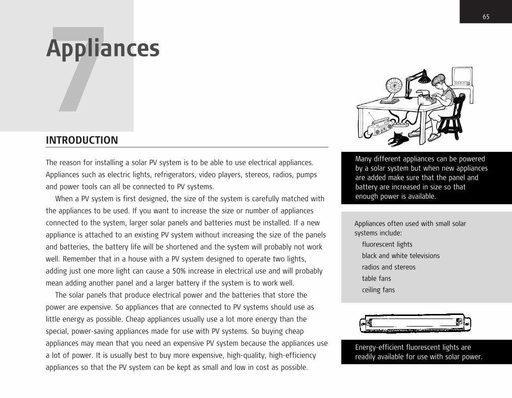
INTRODUCTION
The reason for installing a solar PV system is to be able to use electrical appliances.
Appliances such as electric lights, refrigerators, video players, stereos, radios, pumps
and power tools can all be connected to PV systems.
When a PV system is first designed, the size of the system is carefully matched with
the appliances to be used. If you want to increase the size or number of appliances
connected to the system, larger solar panels and batteries must be installed. If a new
appliance is attached to an existing PV system without increasing the size of the panels
and batteries, the battery life will be shortened and the system will probably not work
well. Remember that in a house with a PV system designed to operate two lights,
adding just one more light can cause a 50% increase in electrical use and will probably
mean adding another panel and a larger battery if the system is to work well.
The solar panels that produce electrical power and the batteries that store the
power are expensive. So appliances that are connected to PV systems should use as
little energy as possible. Cheap appliances usually use a lot more energy than the
special, power-saving appliances made for use with PV systems. So buying cheap
appliances may mean that you need an expensive PV system because the appliances use
a lot of power. It is usually best to buy more expensive, high-quality, high-efficiency
appliances so that the PV system can be kept as small and low in cost as possible.
65
7Appliances
Many different appliances can be poweredby a solar system but when new appliancesare added make sure that the panel andbattery are increased in size so thatenough power is available.
Appliances often used with small solarsystems include:
fluorescent lights
black and white televisions
radios and stereos
table fans
ceiling fans
Energy-efficient fluorescent lights arereadily available for use with solar power.
chapter7.qxd 11/8/03 12:32 PM Page 65

ELECTRIC LIGHTS
The most common appliance is the electric light. There are two main types of electric
light: incandescent and fluorescent. Incandescent lights work by passing enough
electricity through a thin wire to make it so hot that it glows brightly. They waste a lot
of electricity but they are simple and cheap. Fluorescent lights work in a more
complicated way but can provide over twice as much light as an incandescent light for
the same amount of electricity.
When you install lights, remember to place them where the light is most needed,
not just anywhere that seems convenient. If there is just one light in a room,
the best place is usually the centre of the ceiling. In general, if the electric light is
to replace a kerosene wick lamp (hurricane lamp) or pressure lamp, place the
new electric light near where the old lamp was, as that must be where people
needed light.
Always keep the connecting wire as short as possible. Fasten the connecting wire to
the wall or ceiling about every metre. Always fasten the light fixture to the wall or
ceiling or use special hangers, never hang it from the electrical wire unless it is
designed to use the wire as a support.
Never replace a faulty fluorescent light with a 12 V incandescent light from a vehicle.
To get the same amount of light from an incandescent light, the PV system must
provide twice as much power as was needed with the old fluorescent light. Unless more
solar panels and a larger battery are installed to provide this extra power, replacing
fluorescent lights with incandescent lights will cause the battery to fail quickly.
Fluorescent lights made for use with PV systems work on dc electricity at the same
voltage as the battery. If the system has a 24 V battery, the lights must also be
designed for 24 V dc. Because dc electricity has a positive and a negative terminal,
the positive terminal of the light must always be connected to the wire that goes to
66 Solar Photovoltaic Systems Technical Training Manual
Incandescent lights use over twice theelectricity as fluorescent lights and do not lastas long. Never use incandescent lights withsolar power.
Always use the type of light that is best foryour purpose. Place lights where they aremost needed.
chapter7.qxd 11/8/03 12:32 PM Page 66

the positive terminal of the battery and the negative terminal of the light to the
negative terminal of the battery. If wrongly connected, the light usually will not work
and may be damaged.
Also some types of fluorescent light may be damaged if the electricity is turned on
without a bulb in the appliance. Make sure that a fluorescent bulb is fitted before
turning on the electricity.
Although special dc light fixtures must be used, ordinary electrical switches like
those used in city houses can be used to turn the light on and off if they are of good
quality. The type of switch that snaps the contacts together, called a toggle switch,
will last longer and give better service than cheap switches that just slide the contacts
together.
REFRIGERATORS
You can use a small, high-quality refrigerator intended for ac operation by installing
a high-quality sine-wave inverter to convert the solar dc power to mains ac power.
You must not use a modified sine-wave or square-wave inverter because they will cause
the motor to overheat. Sine-wave inverters are expensive. Usually, installing a special
refrigerator designed for solar use will be cheaper. Then you will not need the
expensive inverter. Also, the amount of electricity the solar refrigerator uses will be
much lower than the amount of electricity to run a regular refrigerator. Therefore,
a smaller size of solar panel and battery can be used with the refrigerator made for
solar power.
Because solar-powered refrigerators are often used for remote health centres,
their installation, use and maintenance is discussed fully in Chapter 8.
677 / Appliances
Although it is possible to buy many kinds ofappliance that operate from 12 V dc, theymay be hard to find and expensive. By usingan inverter, the dc power can be convertedto ac. Then regular household appliances canbe used. The disadvantage is that theinverter uses more energy than dc appliancesso the panel and battery may need to belarger.
There are different kinds of inverters, somake sure that the type you buy will operatethe appliances you want to use withoutdamaging them. If the inverter must poweran appliance with a motor, such as a pump ora washing machine, a special high-qualityinverter should be used or the motor may bedamaged. Do not get an inverter larger thanyou need. It will waste energy and cost morethan is necessary.
Always keep the wiring short between the battery and the inverter. The wiring from the inverter to the appliances can belonger as it is at a higher voltage.
chapter7.qxd 11/8/03 12:32 PM Page 67

A refrigerator can use more electricity than 12 lights used 4 hours a day.
If a refrigerator is added to a PV system that has already been installed, make sure
that there are enough panels and batteries to handle the new, large load.
Make sure that the discharge controller will work properly with the refrigerator.
FREEZERS
Refrigerators are usually adjusted so that they never get cold enough inside to
freeze water or food. When they are designed for temperatures that are cold
enough to freeze water, they are called freezers. Although many refrigerators will
get cold enough to freeze food, they are not designed to operate at such a low
temperature and will use much more electricity than a freezer. With a PV system,
you should only use a freezer for freezing food, not a refrigerator turned to its
coldest setting. As electricity is used to make the inside of a refrigerator cold,
setting a refrigerator for colder operation uses more electricity. A freezer is very
cold inside and therefore requires a great deal of electricity. To freeze water or food
will require many more solar panels and much larger battery capacity than just to cool
things without freezing them. A freezer used regularly to freeze food or water may
need twice as many panels and double the battery capacity as a refrigerator that does
not freeze.
Refrigerators and freezers should be installed in a cool room out of the sun.
Remember that the refrigerator gives off heat, so the room should be well ventilated.
68 Solar Photovoltaic Systems Technical Training Manual
A solar refrigerator may use as muchelectricity as 12 lights kept on for 4 hours a day. A conventional refrigerator and aninverter may use as much as 20 lights.
A freezer may use twice as much electricity asa refrigerator.
chapter7.qxd 11/8/03 12:32 PM Page 68

VIDEOS AND TELEVISIONS
Although it is possible to buy a video player and a television set that will operate
directly from a PV system battery, they are not always easy to find. Most videos
and televisions must have a power converter installed to change the low-voltage
dc of the PV system to the higher ac voltage that they need to work. This converter,
usually called an inverter, is expensive and requires extra energy in addition to
the energy used by the appliance. Inverters should be matched in size to the
appliance for the most efficient use of solar energy and should be turned off with
the appliance.
The inverter input is dc so the positive and negative terminals must be connected
correctly. The inverter output is ac so has no positive and negative terminals.
Videos and televisions should be installed in a cool, clean place. When not in use
they may be covered with a cloth or plastic for protection from dust and water,
but when in use the covers should be completely removed to allow air to flow freely
and cool the appliances.
A small black and white television uses little more electricity than a light.
A colour television uses five or six times as much electricity as a black and white
one, so more solar panels and a larger battery may be needed for it to work
properly.
697 / Appliances
A small black and white television may useno more electricity than one light. A colourtelevision of the same size, which wouldneed an inverter to make ac, may use asmuch energy as seven lights.
A small portable radio or stereo may useless energy than one light. A largemachine with the volume turned up highmay use as much energy as three lights.
chapter7.qxd 11/8/03 12:32 PM Page 69

RADIO AND STEREO EQUIPMENT
Radios and stereos may not work directly from the solar power supply. They often
need 6 V or 9 V to operate. A dc/dc converter is needed to change the voltage. If the
appliance is normally plugged into a mains power wall outlet and cannot operate on
batteries, then an ac inverter is needed. If the appliance is normally battery-operated
and has a small socket for a dc power supply, then a dc/dc converter is usually
needed.
Portable radios and stereos usually need less power than a light. Larger stereos
that are not portable may use more energy than two or three lights, so more solar
panels may be needed. Also, the louder the radio or stereo is played, the more
electricity it uses.
OTHER APPLIANCES
Electric drills, fans and small pumps can be powered by a PV system, though expensive
power converters will sometimes be needed.
Special electric irons are available for use with PV systems but they use a lot of
energy so larger panels and a larger battery may be needed if the iron will be used
often.
Any electrical appliance can be operated from a PV system if the system is
large enough to provide sufficient electricity. Because solar panels and batteries are
expensive, appliances that use a lot of energy, such as air conditioners, steam irons
and electric cooking appliances, are not commonly used.
70 Solar Photovoltaic Systems Technical Training Manual
Ceiling fans made especially for solar powerare readily available and may use no moreenergy than a light.
Washing machines made for solar power arehard to find. Using an inverter for a conventional ac washing machine isexpensive because it must be of high qualityto run the motor.
chapter7.qxd 11/8/03 12:32 PM Page 70

SUMMARY
In choosing appliances for use with a PV system, it is always best to choose those
designed for solar power. The appliance voltage requirements must match the voltage
of the battery unless a power converter is also installed. Appliances must not be added
to a PV system without increasing the number of solar panels and the size of the
battery to supply the increased amount of electricity needed.
717 / Appliances
BUSINESS MACHINES
A portable computer is the best choice for use with solar power. It is very energy-efficient and can easily be adapted towork from a 12 V battery. A desktopcomputer is often cheaper but it may requirefive times as much electricity to operate as aportable computer. The cost of the extrapanel and battery capacity to run thedesktop computer will be much more thanthe extra cost of a portable computer. If adesktop computer must be used, always usea flat-screen LCD (liquid crystal display)monitor because it uses much less energythan other types.
Some models of ink-jet printers can be usedwith 12 V dc. Ink-jet printers use littleenergy, not much more than one light. Laserprinters use a lot of energy and are not agood choice for use with solar power.Sometypes of copy machine are very energy-efficient, others are not. Make surethat you use only energy-efficient copymachines with solar power.
Small fax machines use little energy butrarely work with 12 V power, so a smallinverter needs to be instaled.
chapter7.qxd 11/8/03 12:32 PM Page 71

INTRODUCTION
Although solar-powered refrigerators are rare in homes, they are often found in rural
health centres. Many important vaccines and medicines must be stored at carefully
controlled, low temperatures. Solar refrigerators are expensive but provide the only way
that vaccines and medicines can be stored at many remote sites.
REFRIGERATION PRINCIPLES
When you pump a bicycle tyre with a hand pump, the body of the pump feels warm
after a while. Air in the pump is compressed by the piston, heats up and transfers its
heat to the body of the pump. Any process of compression creates heat.
The opposite of compression is expansion. If you let air out of a tyre, the air feels
quite cool. The air was compressed while in the tyre then, when you let the air out,
it expands and cools.
When you wet a rag, the rag cools as the water evaporates to the air. One way to
cool yourself in the tropics is to wet your head and let the water evaporate to remove
some of the heat. As evaporation occurs, heat is removed from the liquid that is
evaporating and it cools.
73
8Photovoltaic-poweredrefrigerators
A system for solar refrigeration uses solarpanels, a controller, a battery and a 12 Vor 24 V dc refrigerator.
PV PanelsBattery
Refrigerator
One way to cool yourself is to wet yourhead. The evaporation of the water hasa cooling effect.
Controller
chapter8.qxd 11/8/03 12:23 PM Page 73

So we can absorb heat and make something feel cool by evaporating a liquid or
expanding a gas.
When you use any kind of spray can, such as insect killer, you may have noticed that
the spray and the tip of the can become cold. What happens is that the high-pressure
liquid in the can both expands and evaporates as you press on the cap. The pressure of
the liquid drops as it goes through the tiny hole in the cap and the liquid evaporates
into the surrounding air. This combination of evaporation and expansion removes heat
from the air, making it feel cold.
COMPRESSION REFRIGERATION
When a refrigerator runs, the cooling unit absorbs heat from the inside of the
refrigerator box then moves the heat to the air outside the box. This warms the air in
the room and cools the inside of the refrigerator. So for the inside of the refrigerator
to be cool, something on the outside must be hot.
Inside a refrigerator, a special liquid is sprayed from a small pipe into a larger pipe.
This makes the liquid evaporate and expand. As it evaporates and expands, the large
pipe becomes cold and a large amount of heat is drawn from the surrounding air.
This cools the inside of the box. The low-pressure gas is then pulled from the large
pipe and raised in pressure by a compressor. Raising the pressure heats the gas.
The high-pressure, hot gas goes through a pipe to the condenser located outside the
refrigerator box. The air in the room can then cool the gas. This turns the gas
back into a liquid, a process called condensing. The pressure from the compressor
74 Solar Photovoltaic Systems Technical Training Manual
Three types of solar photovoltaic refrigeratorsare available today.
The most widely used and generally the mostsatisfactory is the compressor refrigerator. In this type, a refrigerant is circulated and,through mechanical compression and heat transfer, alternates between being a liquid and being a gas. A second commontype is the absorption refrigerator.
In this type, the two materials in the refrigeration circuit get cold when they are mixed together. Kerosene and liquefiedpetroleum gas (LPG) refrigerators use thissystem as they require a high temperature tooperate. Electricity can be used but absorptionrefrigerators use much more electrical energythan compression refrigerators.
The third type is the thermoelectric refrigerator.It uses a solid-state device, similar to a solar cellor a transistor, with two poles. One pole iscooled and one pole is heated when an electriccurrent is passed through the device. This typeof refrigerator can be made very small and isthe best choice where less than a litre ofrefrigeration capacity is needed. The larger sizesusually needed for vaccine storage or domesticuse are very expensive and use considerablymore energy than the compressor type.
chapter8.qxd 11/8/03 12:23 PM Page 74

sends the liquid back into the refrigerator box to evaporate and expand again and
repeat the cycle. This circulating material is called the refrigerant.
So a refrigerator works by circulating the refrigerant through an evaporator,
a compressor, a condenser and an expansion valve in a closed cycle. This closed system
has two pressure zones, a high-pressure zone in the condenser and a low-pressure
zone in the evaporator. The pressure difference is maintained by the compressor and
a device that stops the liquid from flowing too fast, either a tiny tube called a capillary
tube or a more complex device called an expansion valve. The diagram shows the basic
components of a refrigeration system and the two pressure zones.
EVAPORATOR
The evaporator is located in the cold compartment of the refrigerator. The evaporator
is usually made from aluminium and is usually visible in the cold compartment though
sometimes it is moulded inside the plastic walls of the refrigerator compartment so that
you cannot see it. The evaporator is where the high-pressure liquid refrigerant expands
and evaporates causing it to absorb heat from the air in the refrigerator. When the
refrigerant evaporates it becomes a low-pressure gas. In the process, the evaporator
becomes very cold. The vaporized refrigerant leaves the evaporator as a cold,
low-pressure gas and is then sucked into the compressor.
758 / Photovoltaic–powered refrigerators
In a compressor refrigerator, cooling is donein three ways:
1) by expansion of the refrigerant at the capillary tube outlet
2) by evaporation of the refrigerant in the evaporator
3) by direct cooling of the refrigerant in the condenser.
52
1
4
3
Out (high pressure)
Sealed compressor/motor unit
Evaporator (inside cold space - cold )
Condenser (outside cold space - hot)Filter and dryer
Capillary tube (or expansion valve)
12
3
4
5
Block diagram of a compressor-typerefrigerator.
chapter8.qxd 11/8/03 12:23 PM Page 75

COMPRESSOR
The compressor is usually located in the base behind the refrigerator cabinet and is
sealed inside a black metal shell. An electric motor also sealed inside the metal
shell drives the compressor, and the two together are called the compressor unit.
Its function is to suck in the cold, low-pressure gas from the evaporator and increase its
pressure. It also raises the temperature of the gas. The compressor then forces the
hot, high-pressure gas into the condenser. Most refrigerators in the city use an
ac motor to drive the compressor. A photovoltaic-powered refrigerator usually has
a special dc motor to drive the compressor.
CONDENSER
The condenser is usually located on the back of the refrigerator and is always hot
when the compressor is operating. It acts like the radiator used to cool a car engine.
The heat absorbed from inside the refrigerator by the refrigerant in the evaporator is
compressed and passed through the condenser so that the heat can be carried away by
the surrounding air. As the hot, high-pressure refrigerant cools, it condenses into
a liquid. The condenser must cool the hot gas as much as possible for the inside of the
refrigerator to remain as cool as possible. Any heat that cannot leave at the condenser
is sent back into the refrigerator and the refrigerator does not work well. Because of
the large amount of heat that must be lost from the condenser, the condenser must be
clean and cool air must be able to flow over the hot condenser pipes.
76 Solar Photovoltaic Systems Technical Training Manual
Heat moves from inside the refrigerator intothe refrigerant at the evaporator. It is thenforced into the condenser by the compressor.At the condenser, the heat absorbed in therefrigerant passes to the outside air. Leastelectricity is used when heat moves easily intothe evaporator and out of the condenser.
If there is ice on the evaporator or dirt on thecondenser, the heat will move more slowly andthe refrigerator will need more energy forcooling.
If the compressor is dirty, it will get hot andthat heat will pass into the refrigerant, forcingthe condenser to lose more heat than normal.More energy will be needed as a result.
Therefore it is important to keep therefrigerator clean and to defrost it whenevermore than a few millimetres of ice haveformed on the evaporator.
chapter8.qxd 11/8/03 12:23 PM Page 76

EXPANSION VALVE
The refrigeration cycle is complete when this cooled, high-pressure liquid expands
into the evaporator through a flow-restricting device, the capillary tube or expansion
valve. The purpose of the flow restrictor is to allow a high pressure to exist on the
compressor side and a low pressure on the evaporator side of the refrigeration circuit.
Most small refrigerators use a very small diameter copper capillary tube for restricting
the flow of refrigerant. The diameter of this tube is much smaller than the condenser
tubing, restricting the flow and causing a large pressure drop in the liquid refrigerant
from the condenser. Without this flow restriction, the hot refrigerant in the condenser
would not have time to lose its heat before flowing back into the refrigerator.
ACCESSORIES
Although the basic system described above will work, for long life and best operation
other components are included. At the outlet of the condenser, a device called
a strainer-drier traps scale, dirt and moisture to prevent blocking of the flow restrictor.
All refrigerators also have a thermostat that controls the on/off operation of the
compressor unit by measuring the inside temperature of the refrigerator and turning
the compressor on when the cold compartment gets too warm or off when it gets
too cold.
778 / Photovoltaic–powered refrigerators
The energy to keep a vaccine refrigeratorcool is needed mainly to remove outside heat that leaks into the cold compartment.The cabinet is therefore a very importantcomponent of a refrigerator. It has to bewell insulated, solidly constructed andresistant to corrosion. The door must fittightly. The door hinges and latches shouldbe well made and hold the door firmly inplace without leaking, even when the sealsare old.
A typical vaccine refrigerator with top-opening lid, external batteries and the compressor and condenser in the mainhousing.
chapter8.qxd 11/8/03 12:23 PM Page 77

PHOTOVOLTAIC-POWERED COMPRESSION REFRIGERATORS
■ Cabinet
All the solar refrigerator components are housed in a cabinet that is a closed insulated box.
The cabinet may be vertical with the door on the front or horizontal with the door on the top.
These cabinets are very well insulated and their doors have tight seals to prevent cold air from
escaping from the cold compartment. Photovoltaic refrigerators need to be very well insulated
because of the high cost of producing electricity from solar panels. High-quality insulation is
used to reduce heat flow from the warm air outside to the cool air inside the cabinet.
Polyurethane foam is commonly used as insulation and its thickness varies from 5 cm to
12 cm for refrigerators and up to 15 cm for freezers. Door seals are carefully designed and
installed to reduce cold air leaks around the door. Double rows and sometimes triple rows of
door gaskets are often used on photovoltaic-powered refrigerators to reduce leakage to
a minimum.
As cold air is heavier than warm air, every time you open the front door of a vertical
refrigerator, cold air pours out of the interior. With a top-opening chest-type refrigerator,
the heavy cold air stays in the cold compartment and less cold air is lost. Most photovoltaic
refrigerators have a top-opening door because these are the most efficient. Readily available
solar refrigerators have a capacity from less than 50 litres to over 300 litres. The cabinet is
often divided into a main refrigerator compartment and a freezer box for making ice. Some
small refrigerators do not include a freezer compartment.
78 Solar Photovoltaic Systems Technical Training Manual
The energy needed to keep a refrigerator coolis determined by the difference in temperaturebetween the inside of the refrigerator,whatever is placed in the refrigerator forcooling, and the outside air.
A typical, good-quality solar PV vaccinerefrigerator will use around 275 Wh/day ofenergy when the inside is 8 �C and the outside30 �C and the door kept closed.
Opening the door of a refrigerator allowswarm air to enter the cold compartment.About 1 Wh will be needed to cool that air to 8 �C.
Placing 1 litre of water or vaccine in therefrigerator requires about 45 Wh to cool itfrom 30 �C to 8 �C.
Freezing 1 litre of 30 �C water takes as muchas 200 Wh of energy.
Thus in a refrigerator that is opened five timesper day, freezes 2 litres of water per day andcools ½ litre of vaccine per day, the totalenergy use will be about:
Base load = 275 Wh/day
Door openings = 5 × 1 = 5 Wh/day
Freezing water for ice packs = 200 × 2 = 400 Wh/day
Cooling ½ litre of vaccine = 45 × ½ = 22.5 Wh/day
So the total energy use will be about:
275 + 5 + 400 + 22.5 = 702.5 Wh/day
chapter8.qxd 11/8/03 12:23 PM Page 78

■ Compressor unit
A photovoltaic refrigerator is identical to a regular ac refrigerator except that it is powered by
dc electricity and is usually better insulated. The refrigerator is connected to the PV system just
like any other appliance. Most solar refrigerators use a Danfoss brand compressor unit that has
proved to be highly reliable through wide use in marine, vehicle and PV applications.
Usually, dc motors have a mechanical switching unit called a commutator. The commutator
receives the electrical power for the motor through two or more carbon brushes. While this
is low in cost and reliable, the brushes wear out and have to be replaced regularly. As the
compressor motor is sealed inside a metal case, brushes cannot be used because they cannot be
replaced when they wear out. In the Danfoss dc compressor unit, the commutation is done by
an electronic control unit that senses the rotation of the motor and reverses the dc current at
precisely the right time to keep the motor turning just like a mechanical commutator and
brushes in a conventional dc motor.
Sometimes the Danfoss control unit is called an inverter because it converts dc into a form
of ac. Though technically it is a type of inverter, it cannot be used to power anything but the
particular model of Danfoss compressor it is built for. A Danfoss compressor cannot be powered
from any other type of inverter.
Danfoss compressor units are available for either 12 V or 24 V operation and are usually
supplied with an electronic commutator unit that also acts like a discharge controller.
The electronic unit turns off the power to the compressor if the input voltage falls below about
10.5 V and turns it back on as soon as the voltage reaches 11.5 V. If the voltage falls too low,
the compressor will try to start four times with 20 seconds between attempts. If the voltage
stays too low and the motor cannot start, the control will turn off the power to the motor until
the voltage rises to about 11.5 V. It also protects the motor from overheating. Overheating can
be caused by too frequent starting or operating in a very hot room. Usually a fuse is also fitted
to protect against damage from polarity reversal during installation.
798 / Photovoltaic–powered refrigerators
Exercise 1
The manufacturer states that a refrigeratortakes 325 Wh/day to cool to 8 �C when theoutside air is 32 �C. It will be used to maketwo ½ litre ice packs per day and about1 litre of water and vaccines will be cooledeach day. It will be opened about six times aday. About how many watt-hours per day willthe battery need to supply to operate therefrigerator?
Base load = 325 Wh/day
Ice-pack load = 1 × 200 = 200 Wh/day
Cooling load = 1 × 45 = 45 Wh/day
Opening load = 6 × 1 = 6 Wh/day
Total load= 325 + 200 + 45 + 6 =576 Wh/day
EExxeerrcciissee 22
The rated base load for a refrigerator isgiven as 290 Wh/day at 30 �C. It will be usedto freeze five ½ litre ice packs each week.Every day it will be opened an average of tentimes and about ½ litre of vaccines addedevery day for cooling. What is the estimatedtotal daily watt-hour load?
Base load = 290 Wh/day
Freezing load = 5 × ½ × 200 = 500 Wh/week= 500 ÷ 7 Wh/day = 71.4 Wh/day
Cooling load = 45 × ½ = 22.5 Wh/day
Opening load = 10 × 1 = 10 Wh/day
Total load = 290 + 71.4 + 22.5 + 10 = 393.9 Wh/day
chapter8.qxd 11/8/03 12:23 PM Page 79

Some refrigerators use membrane-type compressors as in a diaphragm pump. These units are
cheaper than rotary compressors and work well in very small refrigerators, but they are not very
efficient and require more solar panels to operate than the same size refrigerator with a rotary
compressor.
DUTY CYCLE
A thermostat is just an electrical switch connected to the power control unit. It has
a temperature probe inserted into the cold compartment. The thermostat controls the
on/off operation of the compressor unit. As long as power is supplied to the control
unit, the compressor switches on when the thermostat senses an inside temperature
that is too high. When the required temperature is reached, the thermostat switches
off the compressor unit. This on/off cycle will repeat as long as the refrigerator is
powered. The percentage of time the compressor unit is running is called the duty
cycle. For example, a refrigerator with a 60% duty cycle runs the compressor 60% of
the time and it is off the remaining 40%. The duty cycle depends on how the
refrigerator is used, its condition and its design. A 50% duty cycle is typical for
a refrigerator operating normally.
Duty cycle is increased (the compressor runs a larger percentage of the time) when
warm items are added to the refrigerator for cooling. Lowering the thermostat setting
to get a colder temperature also increases the duty cycle.
If the evaporator is covered with thick frost, the heat cannot easily pass from
the air in the refrigerator to the refrigerant inside the evaporator and the compressor
80 Solar Photovoltaic Systems Technical Training Manual
The duty cycle of a refrigerator compressor is the percentage of time it must run to keepthe correct temperature in the refrigerator.The greater the cooling load, the longer thecompressor must run and the higher the dutycycle.
To calculate the duty cycle, estimate the total watt-hours per day then divide by the number of watts the compressor needsto run. This gives the number of hours per daythe compressor actually runs. Then divide thenumber of hours by 24 (hours in a day). The result is the fraction of a day that thecompressor must run. Multiply by 100 to getthe percentage of the day the compressormust run. This is the duty cycle.
Exercise 1
A refrigerator compressor takes 50 W tooperate. The total daily energy it needs to operate is estimated at 700 Wh/day. What is the duty cycle of the compressorexpected to be?
1. Divide total watt-hours per day bycompressor watts:
700 Wh/day ÷ 50 W = 14 hours per day
2. Divide result by 24:
14 ÷ 24 = 0.58
3. Multiply result by 100 to give percentage:
0.58 × 100 = 58%
chapter8.qxd 11/8/03 12:23 PM Page 80

must run longer. The frost reduces the efficiency of the evaporator and increases
the compressor duty cycle, which uses more energy. Therefore it is important for the
efficient operation of the refrigerator to defrost the evaporator regularly.
The same thing happens on the condenser side of the refrigeration
circuit. If the condenser is dirty, the heat lost through the condenser is reduced
and the thermostat will call for more cooling power, which increases the duty
cycle.
The duty cycle also increases when the door is frequently opened, because warm air
enters the refrigerator each time and the compressor must run longer in order to cool
that air. The more you open the door, the longer the compressor will operate before
switching off and the more electrical energy will be needed.
As the room temperature increases, more heat leaks into the refrigerator and it is
more difficult to remove heat from the condenser. Therefore, the duty cycle increases
rapidly as room temperature rises.
Every time the duty cycle is increased, more electricity is used by the compressor.
A Danfoss compressor unit uses about 50 W of energy when running and tests have
shown that the typical energy consumption for a solar refrigerator is about 300 Wh/day
if the door is not opened and there is no load on the cooling unit. The energy
consumption increases as the load increases. When ice is being made, it may go up to
600 or 700 Wh/day. This means that at least 250 Wp of solar panels are needed to
operate a refrigerator reliably in most tropical climates. Typical vaccine refrigerator
systems for rural health centres need 250 to 350 Wp of panel capacity.
818 / Photovoltaic–powered refrigerators
PV refrigerator troubleshooting
Problem: unit is too cold.
Probable causes:
thermostat incorrectly set or faulty.
Problem: unit runs continually but does notstay cold enough.
Probable causes:
(1) low level of refrigerant; (2) badly leakingdoor seal.
Problem: unit does not run continually anddoes not stay cold enough.
Probable causes:
(1) thermostat incorrectly set or faulty; (2) battery often runs down because notenough energy from the panels or too muchenergy used by the refrigerator.
Problem: Battery regularly runs down to the point where compressor will not start.
Probable causes:
(1) too much shade on the solar panels; (2) panels too small; (3) wiring problems atthe panels so not all of them provide power;(4) poor connections somewhere between the panels and the refrigerator; (5) controllerset points incorrect or controller faulty; (6) user trying to cool too many things, orotherwise not using refrigerator properly; (7) battery not functioning correctly.
Problem: Compressor does not run at all.
Probable causes:
(1) wiring or connection problem betweenbattery and refrigerator; (2) faultycompressor or compressor controller; (3) faulty thermostat.
chapter8.qxd 11/8/03 12:23 PM Page 81

MAINTENANCE
The maintenance of solar-powered refrigerators is the same as for standard ac units.
They must be kept clean to operate efficiently and the door seals must be kept in good
condition.
Cleaning the condenser is important because a layer of dirt will act as an insulator
and reduce the efficiency of the appliance. The compressor and electronic control unit
should also be kept clean.
A poorly sealing door is a common reason for high electricity consumption in a
refrigerator. The seals have to be replaced if damaged and the hinges must not be
loose or wrongly adjusted. When the door is shut, there should be no way for warm air
to enter the refrigerator.
82 Solar Photovoltaic Systems Technical Training Manual
PV refrigerator maintenance
The most important maintenance job is toclean all parts of the refrigerator inside andout. Especially: (1) condenser; (2) evaporator(defrost and wipe clean); (3) door seals; (4) compressor and compressor controller.
Temperature and connections need to bechecked. Also do all the regular PV systemmaintenance checks (see Chapter 10).
Every model of refrigerator is slightly different.Always carefully follow the manufacturer’sinstallation and maintenance instructions toget the best service from the unit.
chapter8.qxd 11/8/03 12:23 PM Page 82

INTRODUCTION
For a solar PV system to work properly, the size of the panels and the battery must be
matched with the energy needs of the appliances. Because panels and batteries are
expensive, people often try to save money by installing too few panels or too small
a battery. This is very poor practice and does not really save money, because a system
that is too small for the appliances does not work well and the battery will have to be
replaced, often at high cost.
Sizing PV systems for homes is not difficult if you know what appliances will be used
and how long they will operate each day. Because all the power must come from the
solar panels, it is most important that they are large enough to provide the energy
needed even on cloudy days.
CALCULATING THE CORRECT PANEL SIZE
The energy used by appliances is measured in watt-hours and the energy produced
by the panels is also measured in watt-hours. Watt-hours of energy are like litres
of motor fuel. When 5 litres of fuel are needed to go from one place to another,
if only 4 litres of fuel are provided the motor will stop before the trip is completed.
83
9System sizing
The most common reason for the failure of a PV system is that the panels are too small.Designs are usually based on newcomponents used under ideal conditions. As all parts of a PV system degrade overtime, the system becomes less efficient andthe panels must supply more energy as thesystem ages.
Because panels that are too small do notcharge the battery enough each day, battery life will be shorter than in a systemwith enough panel capacity. Trying to savemoney by using panels that are too smallresults in spending much more on batteryreplacements over the life of the system. It is usually cheaper to add extra PV panels,because battery life is increased and fewerbattery replacements will be needed.
chapter9.qxd 11/8/03 12:25 PM Page 83

In a PV system, if an appliance needs 100 watt-hours a day to work properly and if
the solar panels only produce 80 watt-hours the appliance will stop working early
in the day.
ELECTRICITY LOSSES
If your vehicle’s fuel pipe leaks, you will lose fuel as you travel. In a PV system there
are always electricity leaks. Even if the panels produce a full 100 Wh a day, this will not
be enough to power appliances needing 100 Wh a day because some of the energy
from the panels is lost before it reaches the appliances.
In most solar PV systems, the energy from the panels is first stored in a battery
before it is sent to the appliances. Some energy is always lost in the battery. So some
of the energy provided by the panels never reaches the appliances. Also, a little energy
is always lost in the wires and controller even if the wires are the correct size and the
controller is working. For every 100 Wh needed by the appliances, the panels must
provide at least 130 Wh. The extra 30 Wh are lost in the battery, wires and controller.
■ Calculating appliance watt-hours used each day
To calculate the number of watt-hours needed each day from the panels, first calculate the
number of watt-hours needed each day by the appliances. Then increase the result to cover
the watt-hours lost in the wiring and battery before the energy reaches the appliances.
To calculate appliance watt-hours, multiply the number of watts needed to operate each
appliance by the number of hours each appliance is used per day.
84 Solar Photovoltaic Systems Technical Training Manual
Example 1
If a 10 W light is turned on 2 hours a day anda 120 W fan is operated 3 hours a day, how much energy is used by each appliance in one day? What is the total number of watt-hours used by both appliances in one day?
(Light)
10 W × 2 hours = 20 Wh/day
(Fan)
120 × 3 = 360 Wh/day
(Total usage)
360 + 20 = 380 Wh/day
Example 2
A 20 W light in a church is used on Wednesdaynight for 3 hours and Saturday night for4 hours. The rest of the week it is not used.How much energy will be used each day? What is the daily energy use?
20 W × 3 = 60 Wh on Wednesday
20 W × 4 = 80 Wh on Saturday
So the light uses 60 + 80 = 140 Wh per week.There are seven days in a week, so the lightuses 140 ÷ 7 or 20 Wh per day, on average.
chapter9.qxd 11/8/03 12:25 PM Page 84

Always calculate the energy used on a ‘per day’ basis because the solar panels provide
energy on a daily cycle. Sometimes an appliance is used more on some days than on others.
For example, the lights in a community centre may only be used on Saturdays and Sundays.
In that case calculate the total watt-hours needed per week and divide by 7 to find the
watt-hours needed per day.
So far, we have assumed that there is only one appliance. Usually, there are several.
You have to find the total energy needed by all the appliances each day. So first find the
watt-hours needed per day by each appliance, then add them all together.
■ Calculating total watt-hours needed from the panels each day
When you know the daily energy in watt-hours needed by all the appliances, the total
watt-hours that the panels must provide each day will be that number of watt-hours plus
the watt-hours lost in the wires, battery and controller. A reasonable estimate is that for every
100 Wh used by the appliances, the panels have to produce 130 Wh. Therefore to find the total
watt-hours that the panels must provide each day, multiply the total watt-hours used by
the appliances by 1.3.
■ Estimating the energy output from a solar panel
Photovoltaic panels are made in different sizes. The larger the panel, the more energy in
watt-hours it will produce. Panel manufacturers rate the size of their panels by the watts
of power that they will produce when the sun is at its peak. This is called panel peak watts.
859 / System sizing
Example 3
A house has three lights. One is 20 W and isused 3 hours a day. The second is 10 W andis used 4 hours a day. The third is 2 W and isused 9 hours a day. What is the total watt-hours used by the three lights in a day?
20 W × 3 hours = 60 Wh/day
plus:
10 W × 4 hours = 40 Wh/day
plus:
2 W × 9 hours = 18 Wh/day
The total energy used is:
60 + 40 + 18 = 118 Wh/day.
Example 4
The appliances in a house require 100 Wh perday. How many watt-hours per day must the panels produce?
100 Wh × 1.3 = 130 Wh/day
of which 30 Wh will be lost in the system and100 Wh used by the appliances.
chapter9.qxd 11/8/03 12:25 PM Page 85

On manufacturers’ data sheets, panel peak watts are usually shown as Wp. The peak watts
produced depend not only on the size of the panel but also on the brightness of the sunlight
striking the panel. Therefore, you cannot calculate panel watt-hours by multiplying peak
watts by the hours the sun shines, because the brightness of the sun is constantly
changing as it moves across the sky and it is only at its peak in the middle of the day.
Even at peak sunlight for the day, the brightness of the sun may be reduced by clouds.
So a panel will produce less energy in a cloudy climate than in a sunny climate. To estimate
the energy produced by a panel you need to consider both the size of the panel and the
climate at the location.
Fortunately many measurements have been made of the energy output of solar panels that
can be used to estimate their energy production. These measurements were made over many
years in a tropical Pacific Island location. They show that it is reasonable to estimate that
a 35 Wp solar panel will provide 120 Wh per day on average in a typical tropical, coastal climate
such as found in many developing countries. This type of climate rarely has completely clear
days, but the clouds are generally scattered and it is unusual to have more than three
or four days of continuous cloud. On very clear days the panel will produce more energy,
on cloudier days less, but over many days the average daily output from a 35 Wp panel will be
about 120 Wh in this type of climate.
If a larger panel is used there will be a larger output of energy. If the panel is twice the size
and rated at 70 Wp, it will produce an average of 240 Wh per day, twice as many watt-hours
per day than a 35 Wp panel.
86 Solar Photovoltaic Systems Technical Training Manual
Example 5
A fan uses 200 Wh in a day. How much energywill the panels have to produce each day?
200 × 1.3 = 260 Wh/day
of which 60 Wh will be lost in the system and200 Wh used by the fan.
Example 6
How many watt-hours would you expect a 55 Wp panel to produce in a typical tropicalcoastal climate?
55 × 3.43 = 188.65 Wh/day
Example 7
About how many watt-hours per day will a 75 W panel produce in a typical tropicalcoastal climate?
75 × 3.43 = 257.25 Wh/day.
chapter9.qxd 11/8/03 12:25 PM Page 86

■ Panel Generation Factor
As the average daily energy produced by a 35 Wp panel in a tropical coastal climate is
120 Wh/day, a tiny 1 Wp panel would provide 120 ÷ 35 or 3.43 Wh/day. If a 1 Wp panel
produces 3.43 Wh/day, to find the watt-hour/day from any size of panel all you have to do is
to multiply the peak-watt rating of the panel by 3.43. We call this 3.43 factor the Panel
Generation Factor for that climate. Every climate has a different Panel Generation Factor.
The sunnier the climate, the larger the factor.
■ Finding the number of panels needed
If two panels are joined together, twice as many watt-hours will be produced. Three panels will
produce three times the watt-hours, and so on. The watt-hours produced are the same whether
the panels are connected in series or in parallel.
To find the total peak-watt rating for the PV panels needed to operate the appliances,
find the number of watt-hours that the panels must provide and divide by the Panel Generation
Factor. For a tropical coastal climate the factor is typically 3.43.
To find the peak-watt capacity that will be needed in a system follow these steps:
SStteepp 11.. Calculate the watt-hours per day for each appliance used.
SStteepp 22.. Add the watt-hours needed for each of the appliances to find the total watt-hours
per day needed by the appliances.
SStteepp 33.. Multiply the total appliance watt-hours per day by 1.3 to find the total watt-hours
per day that the panels must provide.
SStteepp 44.. Divide the total watt-hours per day by the Panel Generation Factor for your climate
(3.43 is typical).
SStteepp 55.. Divide the total peak-watt capacity by the peak watts of the panels available to you.
This will give you the exact number of panels needed. Usually the result will not be a whole
number, but of course you cannot install only part of a panel. You must increase any fractional
part of the result to the next whole number to find the number of panels.
879 / System sizing
Example 8
A house has the following appliances in use:
One 18 W light used 4 hours per day
One 60 W fan used 2 hours per day
One 75 W refrigerator that runs 12 hours per day
The system will be powered by 110 Wppanels. How many panels will be needed if the climate is typical tropical coastal (Class 2)?
(Step 1)
Light: 18 × 4 = 72 Wh/day
Fan: 60 × 2 = 120 Wh/day
Refrigerator: 75 × 12 = 900 Wh/day
(Step 2)
Total appliance use = 72 + 120 + 900= 1,092 Wh/day
(Step 3)
Panel energy needed = 1.3 × 1,092
= 1,419.6 Wh/day
(Step 4)
Wp of panel capacity needed = 1,419.6 ÷ 3.43 = 413.9 Wp
(Step 5)
Number of panels needed = 413.9 ÷ 110
= 3.76 panels.
Actual requirement = 4 panels.
chapter9.qxd 11/8/03 12:25 PM Page 87

The number of panels calculated by this method is the minimum number. If more panels
are installed, the system will perform better and battery life will be lengthened. If less
panels are used, the system may not work at all during cloudy periods and battery life will be
shortened.
ADJUSTING THE GENERATION FACTOR FOR DIFFERENT CLIMATES
The amount of energy from the panels will be greater than our estimate if the climate
is sunnier than a tropical coastal climate. Also, the energy from the panels will be less
than our estimate if the climate is cloudier than a tropical coastal climate.
Some climates are seasonal, with many more cloudy days in one season than in
another. The size of the system has to fit the cloudiest season if it is to give service all
year round. To make a reasonable estimate of the panel output for different climates,
you can use the following guidelines:
Climate Class 1
Sunnier than the tropical coastal climate with many days of clear skies and few cloudy
periods longer than four days. A desert location may be in this class. For this climate,
use a Panel Generation Factor of 3.86.
Climate Class 2
A tropical coastal climate with most days partly cloudy. Fully cloudy periods are usually
no more than five days long. For this climate, use a Panel Generation Factor of 3.43.
88 Solar Photovoltaic Systems Technical Training Manual
Example 9
A video system that needs 200 W to operate isused 4 hours a week. What Wp of panelcapacity will be needed to provide enoughenergy in a typical Class 2 tropical coastalclimate?
200 W × 4 hours = 800 Wh/week
800 ÷ 7 = 114.29 Wh/day
If 114.29 Wh/day are required by theappliances, 114.29 × 1.3 = 148.58 Wh/day mustbe provided by the panels.
1 Wp of panel can be expected to produce3.43 Wh/day.
So at least 148.58 ÷ 3.43 = 43.3 Wp of panelcapacity will be needed.
Example 10
The total appliance watt-hour per dayrequirement for a house system using a 12 Vbattery is 260 Wh/day. What total watt-hoursmust a battery store in order to operate theappliances for 5 days?
5 × 260 = 1,300 Wh
chapter9.qxd 11/8/03 12:25 PM Page 88

Climate Class 3
Cloudy periods of five to seven days occur regularly but are typically followed by three
or more clear days. For this climate use a Panel Generation Factor of 3.0.
Climate Class 4
Cloudy periods of ten or more days occur regularly and fully clear days are unusual.
For this climate use a Panel Generation Factor of 2.57.
Remember that you must use the cloudiest season for this calculation even though
part of the year the climate may be very clear and sunny. If the system is not sized to
allow for the cloudy season, then it will not work properly at that time of year.
BATTERY SIZE
A battery is needed because the appliances use electricity at different times and at
different rates than the panels produce. For the system to work properly, the battery
should be of the deep-discharge type and be large enough to store enough energy
to operate the appliances at night and on cloudy days. Also, for the battery to last
a long time, it should not be discharged too much or too often. In sizing a battery,
it is important to install one large enough to operate the appliances for at least five
days without recharging. In climates that have long periods of cloudy weather, a larger
battery may be needed.
899 / System sizing
Example 12
How many 40 Wp panels will be needed forthe conditions in Example 11 if the climate isa Class 3 continental climate?
Panel watt-hours per day must still be260 Wh/day
The total peak watts must be:
260 ÷ 3.0 = 86.7 Wp in a Class 3 climate
therefore the number of panels will be:
86.7 ÷ 40 = 2.16 panels,
so three panels will be needed.
Example 11
Appliances in a house need 200 Wh/day tooperate. How many 40 Wp panels will beneeded if the climate is typical Pacific Island?
The panels must produce 200 Wh/day plus the energy lost in the system:
200 � 1.3 = 260 Wh/day.
The total Wp needed will be:
260 ÷ 3.43 = 75.8 Wp
Therefore it will take:
75.8 ÷ 40 = 1.89 panels to do the job.
Therefore at least two panels will have to beinstalled.
chapter9.qxd 11/8/03 12:25 PM Page 89

Remember that battery life depends on how much discharge takes place before a
recharge. So another way of sizing a battery is that the battery should be large enough
so that one day’s use of the appliances will discharge it no more than one-fifth of its
full charge. This limited discharge before recharging will help the battery to last a long
time.
When buying a battery, the voltage and the ampere-hour rating must be
known. For a solar PV system in a home the voltage will usually be either 12 V or
24 V. The size in ampere-hours will depend on the energy requirements of the
appliances.
As the battery should store five times the energy that the appliances use in one day,
the watt-hour capacity needed in the battery is the total appliance watt-hours per day
times 5.
Because manufacturers rate their batteries in ampere-hours, not watt-hours,
you need to convert the calculated watt-hours to ampere-hours. As watts equals volts
times amperes, dividing watt-hours by the battery voltage gives ampere-hours.
When you know the total watt-hour capacity of the battery, you can calculate the
ampere-hour capacity by dividing watt-hours by the battery voltage:
1,300 Wh ÷ 12 V = 108.33 Ah.
For this example, the battery chosen should be a 12 V deep-discharge battery with
at least a 108.33 Ah rating.
90 Solar Photovoltaic Systems Technical Training Manual
EExxaammppllee 1133
A house with a 12 V solar system has the following appliances in use:
One 18 W light used 4 hours per day
One 60 W fan used 2 hours per day
One 75 W refrigerator that runs 12 hours per day
What battery capacity will be needed?
(Step 1)
Light: 18 � 4 = 72 Wh/day
Fan: 60 � 2 = 120 Wh/day
Refrigerator: 75 � 12 = 900 Wh/day
(Step 2)
Total appliance use:
72 + 120 + 900 = 1,092 Wh/day.
(Step 3)
Total appliance watt-hours � 5 = 1,092 � 5
= 5,460 Wh
(Step 4)
Divide watt-hours by battery voltage
5,460 ÷ 12 = 455 Ah
So, for the house in the example, a deep-discharge battery of at least 455 Ahshould be used.
The rule for battery size is toinstall a battery that has at leastfive times as much capacity aswill be needed to operate theappliances for one day.
chapter9.qxd 11/8/03 12:25 PM Page 90

For these calculations, we are assuming a battery rated at C10 discharge rate,
not C100. If the battery manufacturer rates batteries at C100, you will need to increase
the size of the battery you buy by multiplying the C10 calculated value by 1.3 to get the
C100 capacity battery to install.
Remember that if a deep-discharge battery cannot be found and you have to use
a vehicle starting battery, it is best to choose one with at least twice the ampere-hour
capacity than would be correct for the deep-discharge battery. Even then, it will
probably not last as long as a deep-discharge battery. A ‘maintenance-free’ battery
that does not allow access to the cells for water replacement should be about 1.5 times
larger than would be correct for a deep-discharge battery.
■ Summary of battery size calculations
SStteepp 11.. Calculate the watt-hours per day used by each appliance.
SStteepp 22.. Total the watt-hours per day used by all appliances.
SStteepp 33.. Multiply the total appliance watt-hours per day by 5 for a deep-discharge
battery, multiply by 7.5 for a maintenance-free battery or multiply by 10 for a vehicle
battery.
SStteepp 44.. Divide the result of Step 3 by the battery voltage. The result will be the
required ampere-hour capacity of a deep-discharge battery at a C10 discharge rate.
If the battery you want to use has the ampere-hour capacity rated at the C100 discharge
rate, you need to multiply the calculated ampere-hour size by about 1.3. So if you
calculate the C10 rate as 100 Ah, you need to buy a battery with a rating of at least
130 Ah at C100.
919 / System sizing
Too small a system will run out of power whenthe weather is cloudy and will cause batteries tofail more often. Whenever a PV system is notworking properly, always check to make surethat the panels and battery are large enough toprovide the watt-hours needed to operate theappliances each day.
If the system is too small, you must eitherincrease the number of panels or reduce theenergy needed by the appliances, by using fewer appliances or using them for a shortertime.
A larger battery may also be needed, but installing a larger battery without firstinstalling more panels will not help. If you do not increase the number of panels, the systemwill continue to work poorly and the battery life will remain short.
chapter9.qxd 11/8/03 12:25 PM Page 91
SYSTEM MODIFICATIONS AND SIZING
The size of the panels and the battery are both determined by the watt-hours used by
the appliances. The number of watt-hours changes when appliances are added or
removed from the system and when appliances are used more or less each day.
If you have more panels and a larger battery than you need, it is not a problem.
It is a problem, however, when the panels or battery are too small. People often want
to add appliances to an existing PV system. If they do, the system will not work
properly unless the panels and battery are large enough to provide the extra
watt-hours. Whenever a new appliance is added, or an old appliance replaced by
a new one, it is important to recalculate the correct panel and battery sizes and
to increase the system capacity to handle any increased load.
It is also common for people to underestimate the amount of time that lights and
other appliances will be used. If the PV system size is calculated using estimates of
appliance use that are too low, then the system will not be powerful enough and will
not work well.
BATTERY LIFE AND PANEL SIZE
It has been shown that increasing the panel size increases battery life, particularly in
a climate with frequent cloudy conditions. With the cost of solar panel capacity falling
92 Solar Photovoltaic Systems Technical Training Manual
In calculating the ampere-hour capacity of abattery, use the actual watt-hours needed bythe appliances, not 1.3 times that amount aswith the panels. There is some loss of energybetween the battery and the appliances butthis is small enough to ignore in calculatingbattery size.
BBaatttteerryy ssiizziinngg ccaallccuullaattiioonn
SStteepp 11.. Calculate the watt-hours per day usedby each appliance.
SStteepp 22.. Total the watt-hours per day used byall appliances.
SStteepp 33.. Multiply the total appliance watt-hours per day by five.
SStteepp 44.. Divide the result of Step 3 by the battery voltage. The result will be therequired ampere-hour capacity of a deep-discharge type battery at a C10
discharge rate.
If a vehicle battery is to replace a deep-discharge battery, the vehicle batteryshould have about twice the ampere-hourcapacity as the deep-discharge battery if it is to last a reasonable time.
chapter9.qxd 11/8/03 12:25 PM Page 92

but the cost of batteries slowly increasing, it makes good economic sense to increase
the panel size by 20% to 30% over the minimum. This can dramatically improve the
reliability of the system during cloudy weather and can greatly extend the life of
the battery. This reduces the cost over time as battery replacements are now the most
expensive component in a home PV system.
CONTROLLER SIZE
The charge controller has to have enough ampere capacity to pass the maximum
current that the panels can provide. This can be estimated by dividing the peak-watt
rating of the panels by 12 V. So a controller connected to a 100 Wp panel should have
a charging capacity of at least 100 ÷ 12 = 8.33 A.
Most appliances need more amperes to start than to keep running. Electric
motors in particular may need three times as much current to start as they need
to keep them running. So the discharge controller must have enough ampere
capacity to pass the maximum load current, including the extra starting current.
The minimum ampere capacity of a discharge controller should be equal to the
sum of the amperes from all appliances without motors times 1.5, plus the amperes
from all appliances with motors times 3. For example, four lights of 12 W capacity
939 / System sizing
The accuracy of any PV system designdepends on the accuracy of estimates ofappliance use. Estimates are rarely very goodin the long term. People often underestimatethe amount of time that appliances will beused. This results in more energy being usedthan the system was designed for.
People may also add more appliances to anexisting PV system. This increases theamount of energy needed and the system isthen too small.
The best way to make sure that sufficientpanel and battery capacity is available is tokeep checking the system and if the panelsconsistently supply too little energy, asshown by frequent power cuts or a lowaverage battery charge, then more panelsand possibly a larger battery should beinstalled.
chapter9.qxd 11/8/03 12:25 PM Page 93

have a total operating load of 4 A. So the controller should have a capacity of at
least 4 A × 1.5 = 6 A. If a motor that needs 3 A to run is added to the load,
the controller capacity should be increased by another 9 A (3 A × 3)to give a total
capacity of 15 A.
CONCLUSION
Although a smaller system may be cheaper at first, it is often more expensive in the
long term. Trying to save money by installing too few panels or too small a battery only
leads to an unreliable system with a high maintenance cost.
94 Solar Photovoltaic Systems Technical Training Manual
Example 14 – controller sizing
Charge controller:
A 24 V PV system includes 300 Wp of panels.What size charge controller is needed?
Divide the panel peak watts by the systemvoltage to find the charge controller amperes:
300 ÷ 24 = 12.5 A minimum charge controllercapacity at 24 V
Discharge controller:
The above PV system operates:
Four 18 W fluorescent lights
One 60 W refrigerator
One 35 W television
What size discharge controller is needed?
18 W ÷ 24 V = 0.75 A per light
35 W ÷ 24 V = 1.46 A for the television
4 × 0.75 + 1.46 = 4.46 A running current
4.46 × 1.5 = 6.7 A for starting
For the refrigerator:
60 W ÷ 24 V = 2.5 A
2.5 A × 3 = 7.5 A for starting
So the discharge controller should be rated atleast 6.7 + 7.5 = 14.2 A at 24 V
chapter9.qxd 11/8/03 12:25 PM Page 94

INTRODUCTION
For something to last a long time and work properly, it must be cared for. A house,
a boat, even your own body, will last longer and perform better if it is well looked
after. This continuing care is called maintenance. Solar PV systems also require
continuing maintenance if they are to last a long time and work well.
It is always better to stop a boat from leaking by regular care instead of waiting
until it sinks. With a solar PV system, it is much better to check everything regularly
and to fix small problems before they become large ones. Although maintenance
includes repair of the system, it is better to keep systems from breaking down than to
just do maintenance when something is broken. The kind of maintenance that prevents
problems is called preventive maintenance and this is what is described for PV systems
in this chapter.
Because preventive maintenance for PV systems is so simple and so little seems to
be done at each visit, it may seem unimportant. It is not unimportant. Small problems,
like little cracks in a boat hull, soon become large problems if not taken care of.
By doing regular maintenance you may avoid a major repair later.
95
10Maintenance
It does not take much time and money toregularly maintain a solar PV system but itmay take a lot to repair the system if itfails. Regular maintenance makes thedifference between a PV system thatworks without problems for years and onethat is always breaking down.
chapter10.qxd 11/8/03 12:26 PM Page 95
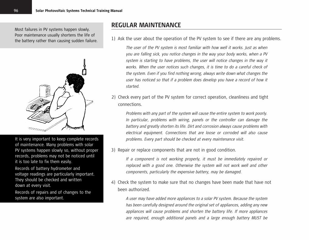
REGULAR MAINTENANCE
1) Ask the user about the operation of the PV system to see if there are any problems.
The user of the PV system is most familiar with how well it works. Just as when
you are falling sick, you notice changes in the way your body works, when a PV
system is starting to have problems, the user will notice changes in the way it
works. When the user notices such changes, it is time to do a careful check of
the system. Even if you find nothing wrong, always write down what changes the
user has noticed so that if a problem does develop you have a record of how it
started.
2) Check every part of the PV system for correct operation, cleanliness and tight
connections.
Problems with any part of the system will cause the entire system to work poorly.
In particular, problems with wiring, panels or the controller can damage the
battery and greatly shorten its life. Dirt and corrosion always cause problems with
electrical equipment. Connections that are loose or corroded will also cause
problems. Every part should be checked at every maintenance visit.
3) Repair or replace components that are not in good condition.
If a component is not working properly, it must be immediately repaired or
replaced with a good one. Otherwise the system will not work well and other
components, particularly the expensive battery, may be damaged.
4) Check the system to make sure that no changes have been made that have not
been authorized.
A user may have added more appliances to a solar PV system. Because the system
has been carefully designed around the original set of appliances, adding any new
appliances will cause problems and shorten the battery life. If more appliances
are required, enough additional panels and a large enough battery MUST be
96 Solar Photovoltaic Systems Technical Training Manual
It is very important to keep complete recordsof maintenance. Many problems with solar PV systems happen slowly so, without properrecords, problems may not be noticed until it is too late to fix them easily.
Records of battery hydrometer and voltage readings are particularly important.They should be checked and written down at every visit.
Records of repairs and of changes to thesystem are also important.
Most failures in PV systems happen slowly.Poor maintenance usually shortens the life ofthe battery rather than causing sudden failure.
chapter10.qxd 11/8/03 12:26 PM Page 96

9710 / Maintenance
Pigs, mice, rats, dogs, birds and insectshave all been known to cause damage toPV system wiring and components. Alwaysvisually check all wires and components fordamage and insect nests.
installed at the same time as the new appliance otherwise the system will
soon fail.
5) Make a record of any action taken during the maintenance visit.
Problems with PV systems often develop slowly. If careful records are kept, it will
be much easier to see what repairs are needed when the system finally does
break down. Also, a record of maintenance activities will show if any particular
components are not working the way they are supposed to and better
components can be chosen in future.
RULES FOR MAINTENANCE
To be useful, maintenance must be carried out on a regular basis. A monthly check is
best for batteries, though a very thorough check of all components should be done at
least every six months.
■ Panels
1. Check the panel mounting to make sure that it is strong and well attached. If it is broken or
loose, repair it.
2. Check that the glass is not broken. If it is, the panel will have to be replaced.
3. Check the connection box to make sure that the wires are tight and the water seals are not
damaged.
4. Check to see if there are any shade problems due to vegetation or new building. If there
are, make arrangements for removing the vegetation or moving the panels to a shade-free
place.
■ Wires
1. Check the wire covering (insulating sheath) for cracks or breaks. If the insulation is damaged,
replace the wire. If the wire is outside the building, use wire with weather-resistant
insulation.
Check panels regularly for dirt, shade, tight connections and secure mounting.
chapter10.qxd 11/8/03 12:26 PM Page 97

2. Check the attachment of the wire to the building to make sure that it is well fastened and
cannot rub against sharp edges when the wind blows.
3. If someone has changed the wiring since the last check, make sure that it is the correct size,
that it has suitable insulation, that the connections are properly made and that it is fastened
securely in its new place.
4. If someone has added more wires to the PV system to operate additional appliances, advise
the owner that this may seriously lower the reliability of the system. Advise increasing the
panel and battery capacity to handle the increased load.
5. Check the connections for corrosion and tightness.
■ Controller
1. Check that the controller is still firmly attached. If it is not, attach it correctly with screws.
2. Keep the controller clean.
■ Appliances
1. Turn on each appliance and check that it is working properly.
2. Check that appliances are mounted securely. If loose or incorrectly mounted, attach them
securely.
3. Clean all exposed parts of each appliance. Clean light bulbs and plastic covers.
■ Maintenance-free battery
1. Check connections for tightness and corrosion. Clean and tighten as needed.
Cover connections with heavy grease. Do not get the grease on any part of the battery
except the connections.
2. Clean the battery with fresh water and a rag.
■ Open-cell battery
1. Clean the top of the battery. Check connections for tightness and corrosion. Clean and
tighten as needed.
98 Solar Photovoltaic Systems Technical Training Manual
One of the most important maintenance tasksis cleaning all components. PV systems workbetter and longer if they are kept clean.
Controllers must be checked for loose wiresand secure mounting. They should be openedand checked for cleanliness and insects.
chapter10.qxd 11/8/03 12:26 PM Page 98

2. Check each cell with a hydrometer and record the readings. When checking take off one cap
at a time. Do not remove all caps at once because that greatly increases the risk of dirt
getting into the cells.
3. If any cells are low on water, add distilled water to raise to the correct level. Never
add more acid, only water. If distilled water is not available, carefully collected rainwater
can be used. Remember that any salt, minerals or oil in the water will poison the battery
and shorten its life, so be very careful about collection and storage of water for the
battery.
4. If any of the caps for the cells have been lost or broken, cover the fill holes loosely with
plastic or glass until proper replacement caps are available. Never cover the holes with
paper, cork, cloth or metal. Never leave the holes uncovered. Be careful that the temporary
cover that you install does not plug the holes tightly because the cells must have air.
5. Clean the battery with fresh water and a rag.
■ Maintenance records
As long as a solar PV system is working well, maintenance records have little value but they
become very important when something goes wrong. By looking at the maintenance records it
is often possible to immediately see what is wrong with a system. It is also possible to see
problems developing with batteries and appliances by looking at well-kept maintenance records.
Maintenance records are also proof that you have taken good care of the system.
Records are kept on a card or small notebook located at each PV system. When the system
is first installed, the manufacturer’s name, model number, serial number and characteristics of
every component should be recorded. A diagram of the electrical circuit showing the connecting
wire size should be made.
At each maintenance visit, the date of the visit and a brief description of any problems and
work done should be written down. If the battery is of the open-cell type, record the
hydrometer readings of each cell and note which cells need water. Any repairs or changes to
the system should be recorded. If new components are added, their manufacturer, model and
serial number should be recorded. If a change is made in the electrical circuit, record the change
on the circuit diagram.
9910 / Maintenance
Maintenance records should be made atthe time of the visit. It is not a good ideato wait until later to write down what you did. You should keep one copy of themaintenance records for yourself and leave another copy at the site in a water-resistant package.
Batteries should be kept clean. Dirt on top ofthe battery may fall into the cells while addingwater. Energy could also be lost from thebattery because a small current could flowthrough the dirt between the connections.
Hydrometer readings for each cell of a battery should be made at every visit. Each reading should be written down alongwith the date and time. If problems occurin the system, the record of thesereadings will be very valuable in findingand repairing the source of the trouble.
chapter10.qxd 11/8/03 12:27 PM Page 99

SPECIAL MAINTENANCE WHEN REPLACING A BATTERY
Never install an expensive new battery in a PV system that is not working perfectly.
When the battery is replaced, the entire system should be carefully checked and
generally overhauled. Take apart and clean all the connections, then reconnect them
correctly. Check the operation of all the appliances and the controller. Generally make
sure that the system is brought back to a new condition.
100 Solar Photovoltaic Systems Technical Training Manual
Clean components work better and last longer.One of the most important maintenanceactivities is cleaning the battery, the controller,the appliances and the panels.
chapter10.qxd 11/8/03 12:27 PM Page 100

INTRODUCTION
Well-designed, well-installed and well-maintained solar PV systems are reliable and can
have a long trouble-free life, but sooner or later there will be a failure. The process of
finding the cause of the failure is called troubleshooting. The process of making
the system work properly again is called repair.
■ Types of System Failure
There are three types of solar PV system failure:
Each type of system failure has a different cause and troubleshooting methods are different.
Failure type 1
The system stops working entirely. None of the appliances work.
Failure type 2
Some appliances work normally, others do not.
Failure type 3
The system works but runs out of power too quickly.
101
11Troubleshooting and repair
TROUBLESHOOTING RULE 1
KNOW HOW THE SYSTEM IS SUPPOSED TO WORK
Problems with PV systems may be due totheir components or to outside effects suchas shade, unusually long periods of cloudyweather or excessive use of appliances.
Unless you know how each componentperforms when operating correctly, you cannot be sure whether the problemscome from inside or outside the system.
When the system is installed, a record shouldbe made of the installation and the operatingcharacteristics of all components. This shouldinclude at least a complete wiring diagram,notes on hours of shade, the number ofamperes required to operate each appliance,the set points of the controller, and the amperes and volts available from the panels at noon on a clear day.
chapter11.qxd 11/8/03 12:29 PM Page 101

FAILURE TYPE 1: TOTAL SYSTEM FAILURE
If the system fails completely, the reason is usually a broken wire, poor connection
or controller failure. The problem is to isolate the fault in the system. First check
the battery charge using a hydrometer or voltmeter.
■ Discharged battery
If the battery is discharged and does not charge when the appliances are switched off for
several days, the fault lies between the battery and the panel.
1) Fuse or circuit-breaker problem. Make sure that all appliances are switched off.
Check any fuse or circuit-breaker in the panel to battery circuit.
Corrective action: Disconnect the loads at the controller. If the fuse is blown,
replace it with the correct type and ampere capacity of fuse. If the circuit-breaker
is tripped, turn it back on. See if the battery will charge. If the fuse or circuit-
breaker blows again or the battery will not charge, there is a problem with the
wiring between the panel and battery or with the controller. Continue with this
checklist. If the fuse or circuit-breaker does not blow, reconnect the load and
turn the appliances on. If the fuse or circuit-breaker blows again, there is a short
in the appliance wiring or in an appliance. See the checklist for failure type 2.
2) Faulty panel or panel wiring. Disconnect the leads to the panel terminals of the
charge controller. Check the voltage across the two wires from the panel when the sun is
shining. If the voltage is less than 12 V, there is a problem with the panel or the panel wiring.
If the voltage is 12 V or more, measure the amperes from the panel. If the amperes are very
low for the panel that is installed, the connections to the panel may be loose or corroded.
Also the panel may be damaged.
Corrective action: Disconnect all the panels and carefully check that each one is
working properly (voltage and amperage). Replace panels that are not working well.
Clean all terminals and wires. Reconnect the panels, making sure that the correct
102 Solar Photovoltaic Systems Technical Training Manual
TROUBLESHOOTING RULE 2
KNOW HOW TO USE YOUR TEST EQUIPMENTAND TOOLS
Electricity is invisible and what is happening inan electrical system can only be understoodfrom the use of electrical test equipment.
The most important test tool is a good qualitymeter for measuring voltage, current andresistance. If you do not fully understand howto use all the controls and features of yourmeter, study the instructions, get help fromsomebody who knows and then practisemeasuring.
Test equipment is useless if it is not workingproperly. Whenever there is doubt about the accuracy of a meter, it should be checked.In any case, any internal batteries should bereplaced and a meter should be fully checkedfor correct operation and accuracy at leastonce a year.
chapter11.qxd 11/8/03 12:29 PM Page 102

wires are connected to the correct terminals. Also make sure that the panels are
not shaded.
3) Battery failure: Check all cells of the battery with a hydrometer. If one or more cells
are very different from the other cells, there is a battery problem. A damaged cell will often
have cloudy electrolyte or a white scum on the electrolyte. If the cell readings are about the
same but very low, or if you have a sealed battery, connect the panel directly to the battery
for several sunny days to see if the battery will fully charge. If it will charge, reconnect
the battery to the system and check the operation of other parts of the system.
Corrective action: If the battery shows damage or will not charge from the panel,
replace the battery and check the panels, controller and wiring. Disconnect, clean
and reconnect all connections. If the battery will charge directly from the panel,
continue with the following checks.
4) Faulty controller. Check the voltage at the battery connections and the panel connections
on the controller when the sun is shining. If the voltage at the battery connection is less than
13.5 V and the voltage at the panel connection is more than 14 V, the controller has probably
failed. Some types of complex, computerized controllers cannot be tested with simple
voltmeters. If that type of controller is thought to have failed, you have to replace
the controller with one known to work properly and wait to see if that cures the problem.
Corrective action: Replace the controller.
5) Faulty wiring between controller and battery. With the battery charged, turn on all
the appliances. Measure the voltage at the battery terminals of the controller and the voltage
directly on the terminals of the battery (not on the battery connections, but on the actual
terminals of the battery itself). If the voltage is more than 0.5 V lower at the controller than at
the battery terminals, there is a wiring problem.
Corrective action: Disconnect all wires, remove connectors from battery terminals.
Clean all connections and wires. Replace wires in connectors and terminals and
tighten all connections. Make sure that the wire connecting the controller and the
battery is the correct size for the current being carried.
10311 / Troubleshooting and repair
TROUBLESHOOTING RULE 3
WHEN A BATTERY IS REPLACED ALWAYSCHECK THAT ALL OTHER COMPONENTS AREWORKING PROPERLY
A battery failure usually happens slowly andis the result of a long series of smallchanges. These changes may be caused frominside the battery due to age or addingimpure water, or from outside the battery.
Outside problems can result in damage dueto over-discharging the battery, leaving itpartially charged for a long time, or stronglyovercharging it. These problems may becaused by:
overusetoo much shadepoor designincorrect installationfaulty wiringfaulty appliancesfaulty controllerfaulty panel
chapter11.qxd 11/8/03 12:29 PM Page 103

■ Charged battery
When the battery is charged but the appliances do not work, there is a wiring fault between
the battery and the appliances.
1) Fuses or circuit-breakers. Check all fuses and circuit-breakers. If they have opened
the circuit there is a short circuit in the wiring or appliances. Check all appliances and the wiring
from the controller to the appliances.
Corrective action: Fix shorted wiring or faulty appliances, replace fuses and
reset circuit-breakers.
2) Wiring between controller and appliances. Turn on at least one appliance and check
the voltage at the load connections on the discharge controller. If the load voltage is about
equal to the battery voltage, the fault is in the wiring between the controller and the
appliances.
Corrective action: Clean all connections, replace all wires that are damaged
or that are not the correct size for their length.
3) Faulty switch. If there is one switch that controls all appliances, it may be the problem.
Using a short wire, connect across the switch terminals. If the appliances work, then the switch
is faulty.
Corrective action: Replace the switch.
4) Controller failure. Measure the voltage at the load terminals and at the battery terminals of
the controller. If the load terminal voltage is zero or much lower than the battery terminal
voltage, the discharge controller may not be working properly.
Corrective action: Replace the controller.
104 Solar Photovoltaic Systems Technical Training Manual
TROUBLESHOOTING RULE 4
KEEP COMPLETE RECORDS OF MAINTENANCEAND REPAIRS AND USE THEM
A complete set of records should be kept fromthe day of installation and they should bechecked whenever the system has problemsand you need to troubleshoot.
In using the records, you should checkparticularly for:
➔ changes in wiring to make sure connectionsand wire sizes are correct
➔ changes in shading from vegetation growth
➔ battery cells that usually measure higher orlower than the rest of the cells
➔ battery cells that take more water thannormal
➔ battery charge levels regularly lower thanother batteries in similar systems that werechecked at about the same time
➔ previous repairs to fix a similar problem.
chapter11.qxd 11/8/03 12:29 PM Page 104

FAILURE TYPE 2: SOME APPLIANCES WORK BUT SOME DO NOT
This type of failure is rarely due to PV panel or battery failure. It may be caused by:
1) A faulty appliance switch. Use a short wire and connect the switch terminals
together. If the appliance works, the switch is faulty.
Corrective action: Replace the switch.
2) An appliance has been wrongly connected. Check the connection at
the appliance. Make sure that the + wire of the appliance is connected to the + wire
of the controller.
Corrective action: Connect the wires correctly.
3) An appliance is faulty. Check the battery voltage. If the battery voltage is low,
there may be a controller problem. If the voltage is over 12 V, use a new wire of the
correct size and connect the appliance directly to the battery. If the appliance does not
work, it is probably faulty.
Corrective action: Repair or replace the appliance.
4) The discharge controller is not working properly. Check the battery voltage.
If it is below 11 V, the discharge controller may be faulty.
Corrective action: Replace the controller and advise the user not to use
the appliances for longer than the system is designed for.
10511 / Troubleshooting and repair
Shading can be seasonal. Because the sunmoves north and south in the sky over the year, trees that do not shade panels atone time of the year may shade themmonths later. Always check for possibleshade problems to the north and south ofthe panels as well as to the east and west.
Solar panels rarely fail. Unless something onthe panel is broken, problems caused by lowoutput are usually caused by shade, poor connections, incorrect wiring or faultyorientation of the panel.
chapter11.qxd 11/8/03 12:29 PM Page 105
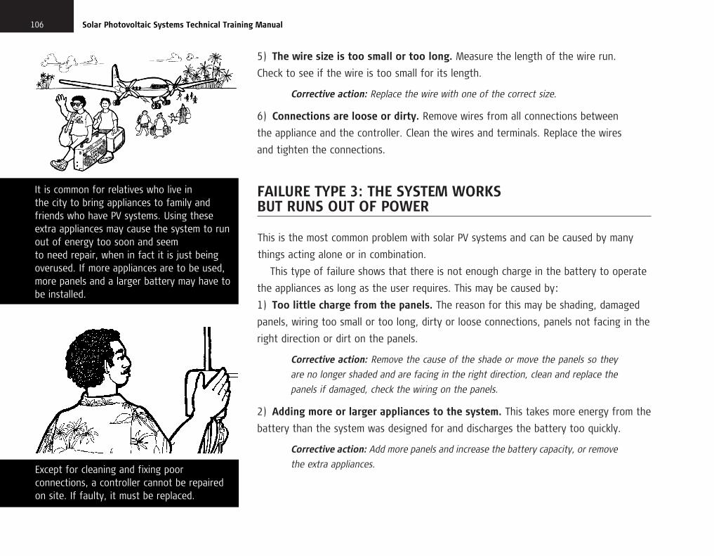
5) The wire size is too small or too long. Measure the length of the wire run.
Check to see if the wire is too small for its length.
Corrective action: Replace the wire with one of the correct size.
6) Connections are loose or dirty. Remove wires from all connections between
the appliance and the controller. Clean the wires and terminals. Replace the wires
and tighten the connections.
FAILURE TYPE 3: THE SYSTEM WORKS BUT RUNS OUT OF POWER
This is the most common problem with solar PV systems and can be caused by many
things acting alone or in combination.
This type of failure shows that there is not enough charge in the battery to operate
the appliances as long as the user requires. This may be caused by:
1) Too little charge from the panels. The reason for this may be shading, damaged
panels, wiring too small or too long, dirty or loose connections, panels not facing in the
right direction or dirt on the panels.
Corrective action: Remove the cause of the shade or move the panels so they
are no longer shaded and are facing in the right direction, clean and replace the
panels if damaged, check the wiring on the panels.
2) Adding more or larger appliances to the system. This takes more energy from the
battery than the system was designed for and discharges the battery too quickly.
Corrective action: Add more panels and increase the battery capacity, or remove
the extra appliances.
106 Solar Photovoltaic Systems Technical Training Manual
Except for cleaning and fixing poorconnections, a controller cannot be repairedon site. If faulty, it must be replaced.
It is common for relatives who live in the city to bring appliances to family andfriends who have PV systems. Using theseextra appliances may cause the system to runout of energy too soon and seem to need repair, when in fact it is just beingoverused. If more appliances are to be used,more panels and a larger battery may have tobe installed.
chapter11.qxd 11/8/03 12:29 PM Page 106

3) Operating the appliances longer than originally intended. This takes more
energy from the battery than the system was designed for.
Corrective action: Add more panels and increase the battery capacity, or the
user must reduce the time appliances are used to the original level.
4) Incorrect adjustment of the charge controller. This may prevent the battery from
fully charging. In some cases a special controller tester will be available but, when it is
not, you can check by asking the user to keep appliance use to a minimum for several
sunny days so that the battery will fully charge. Come to the site in the late afternoon
of the third or fourth sunny day while the sun is still shining. Check the voltage at the
battery terminals and at the panel terminals of the controller. If the two voltages are
about the same and they are both above 13 V for a 12 V system, or 26 V for a 24 V
system, then the charge controller is probably working properly. If the panel voltage is
several volts higher than the battery voltage, and the battery voltage is less than
12.8 V for a 12 V system or 25.6 V for a 24 V system, then the charge controller may be
disconnecting the system too soon and not allowing the battery to fully charge.
For some types of complex, computerized controllers these simple voltage tests do not
work. If that type of controller is installed and is suspected of having failed, you can
only replace the controller with one known to work then wait to see if the system
performs properly.
Corrective action: Replace the controller and send the old one for repair.
5) Incorrect adjustment of the discharge controller. This disconnects the appliances
from the battery before the maximum charge has been taken from the battery.
10711 / Troubleshooting and repair
Whenever a battery has to be replaced,check every part of the PV system,including all wiring, to make sure thateverything is working properly. Otherwisethe new battery may have its life shortened because some other part is faulty.
When you replace a battery, try to find thesame type and size as the one installed inthe PV system when it was new.
chapter11.qxd 11/8/03 12:30 PM Page 107

If the battery shows more than half its fully charged voltage when the appliances go
off, the discharge controller is probably out of adjustment.
Corrective action: Replace the controller and send the old one for repair.
6) The battery is getting weak and can no longer store enough charge to operate
the appliances for long. This can be checked by a battery ampere-hour capacity test.
The battery is likely to be the problem if one or more cells show readings very different
from the others or if the battery is more than four years old. If the battery is less than
four years old, its failure may have been caused by another problem in the system.
Whenever a battery less than four years old must be replaced, check the rest of the
system very carefully. Make sure that the panels are not shaded part of the day and
that the user is not trying to take more energy from the system than it was designed
to deliver. All these things may have seriously shortened the life of the old battery and
if allowed to continue will ruin the new battery as well.
Corrective action: Replace the battery but monitor the replacement carefully.
If after the first month the system once again does not seem to be providing
energy as long as expected, one or more of the other five reasons for failure
exists and must be corrected, otherwise the new battery will also rapidly weaken
and fail.
BATTERY REPLACEMENT
People who do not understand the way a solar PV system works often replace
the battery whenever the system is not working well. Sometimes there was nothing
108 Solar Photovoltaic Systems Technical Training Manual
For some types of panel, shade on just one ortwo cells can greatly reduce panel power.Remember that a small amount of shade ona panel can be a serious problem.
A common reason for a PV system running outof electricity is increased shade from treesthat have grown since the system wasinstalled. For the system to work properly, the trees should be trimmed, the panelsmoved to a sunnier spot, or more panelsinstalled to make up for the smaller amount of sunshine hitting the panels.
chapter11.qxd 11/8/03 12:30 PM Page 108

wrong with the old battery and in a few days or weeks the system again stops working.
Sometimes the battery has failed because of another problem and replacing the battery
with a new one will make the system work for a while, but unless the other problem is
fixed the new battery will soon fail.
The battery is not only the most expensive part of a PV system, it is also the part
most easily damaged. Whenever you have to replace a battery, especially if that battery
is less than four years old, always check the other components to see if they are
working properly and always check to see if the appliances are being used as originally
intended.
Most early battery failures can be traced to either too much shade on the panels
or too few panels in the installation. If shading is not a problem, the system size may
be too small for the load being applied. In any system where the batteries seem to
wear out too quickly, check the adjustment of the controller and, if that is correct,
more panels should be added and a larger battery installed at the next replacement.
10911 / Troubleshooting and repair
A PV system and a rainwater system work in very similar ways. If you have difficultyin understanding a PV system, think ofhow a rainwater system works and it mayhelp you to see what is happening in thePV system.
chapter11.qxd 11/8/03 12:30 PM Page 109

alternating current (ac)
Ampere (A)
ampere-hour (Ah)
battery
charge
circuit-breaker
compressor
condenser
conductor
controller
Coulomb (C)
current
direct current (dc)
discharge
electrical load
electrolyte
energy
evaporator
fluorescent light
fuse
current constantly changes direction
electrical flow rate (intensity or current)
amperes times hours, a measure of electrical volume
a cell or group of cells used to store electricity
fill a battery with electricity by passing a current through it
switch that automatically interrupts an electrical circuit when something goes wrong
device that raises the pressure of a gas
device that converts gas into liquid
material that lets an electric current flow through it easily (the opposite of an insulator)
electrical valve to control the amount of electricity going into or out of a battery
electrical volume
flow of electricity, measured in amperes (A)
current always flows in one direction
release electrical energy from a battery
measure of power needed by an appliance or group of appliances, in watts (W)
liquid used in storage batteries
amount of work done, measured in watt-hours
device that converts liquid into gas
lamp that gives cold light from glowing material inside the tube
safety device that melts to interrupt an electrical circuit if it is overloaded
Glossary
glossary.qxd 11/8/03 11:48 AM Page 111

gauge
Hertz (Hz)
hydrometer
incandescent light
insulator
inverter
kilogram (kg)
kilowatt-hour (kWh)
litre (l or L)
metre (m)centimetre (cm)millimetre (mm)
ohm (�)
parallel
peak watts (Wp)
photovoltaic (PV)
power (W)
pressure
refrigerant
112 Glossary
measuring instrument
measure of frequency of alternating current
instrument for measuring the weight of a liquid compared with water
lamp that gives light when the thin wire inside is heated by an electric current
material that does not let an electric current flow through it easily (the opposite of aconductor)
device to convert direct current into alternating current
measure of weight or mass
1 kWh = 1000 Wh (see watt-hour)
measure of volume (liquid)
measures of length
electrical resistance to flow
joining components in an electrical circuit so that each component is on a different branch ofthe circuit with no current flow in common
watts of power that solar panels will produce under optimum conditions of strong sun andcool temperatures (the greatest amount that can be produced by a panel)
process that uses sunlight to make electricity
ability to do work
force
material that circulates inside a refrigerator to move heat from inside the refrigerator to theoutside air
glossary.qxd 11/8/03 11:48 AM Page 112

113Glossary
semiconductor
series
short-circuit
square centimetre (cm2)square millimetre (mm2)
transistor
Volt (V)
volume
Watt (W)
watt-hour (Wh)
material that lets an electric current flow through it less easily than a conductor, but moreeasily than an insulator (used to make transistors)
joining components in an electrical circuit so that the whole current passes through eachcomponent without branching
faulty or accidental connection in an electrical circuit
measures of area
device to control the flow of electricity
electrical pressure (electromotive force)
measure of the amount of space occupied by something
electrical power
watts times hours, a measure of energy
glossary.qxd 11/8/03 11:48 AM Page 113