uniqunet en 1.01 2015-09 - vbk-technology.de
TRANSCRIPT

vbk technology
uniqunet uniqunet EN 1.01 2015-08

vbk technology
uniqunet EN 1.01 2015-09 2 von 20
Warning Present operating manual is a part of the product. Before installing and using you have to read all safety instructions, warnings and cautions carefully. Make sure that the warning labels are in readable conditions, replace missing or damaged ones.
Contact data for further information vbk technology GmbH Verlängerte Goethestraße 9 08209 Auerbach Tel.: +49 (0)3744 / 22 47 914 Fax: +49 (0)3744 / 22 35 595 [email protected] www.vbk-technology.de
table of content
1 General Information ................................................................................................................. 3
2 Overview .................................................................................................................................. 6
3 Features .................................................................................................................................. 6
3.1 Basic features of the devise .............................................................................................. 6
3.2 Inputs and Outputs ........................................................................................................... 6
3.3 Fan Network – RS485 link ................................................................................................ 7
4 Installation ............................................................................................................................... 8
4.1 Ambient Operating Conditions .......................................................................................... 8
4.2 Mechanical Installation ...................................................................................................... 9
4.3 Electrical Installation ....................................................................................................... 10
4.3.1 Connection Overview .................................................................................................... 10
4.3.2 Connection Details ........................................................................................................ 11
5 Working with uniqunet ........................................................................................................... 15
5.1 Software ......................................................................................................................... 15
5.2 Commissioning ............................................................................................................... 16
5.2.1 Quick Commissioning – fan driven by speed setting ................................................ 16
5.2.2 Quick Commissioning – fan driven by closed loop control ........................................ 16
6 Technical Data ....................................................................................................................... 17
7 Additional Hints ...................................................................................................................... 19
7.1 Manufacturing ................................................................................................................. 19
7.2 Packing and Shipping ..................................................................................................... 19
7.3 Service ........................................................................................................................... 19
vbk technology
uniqunet EN 1.01 2015-09 3 von 20
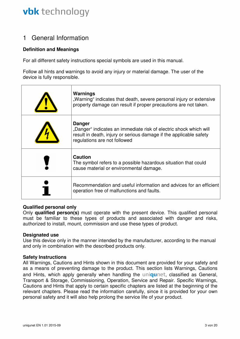
1 General Information Definition and Meanings For all different safety instructions special symbols are used in this manual. Follow all hints and warnings to avoid any injury or material damage. The user of the device is fully responsible.
Warnings „Warning“ indicates that death, severe personal injury or extensive property damage can result if proper precautions are not taken.
Danger „Danger“ indicates an immediate risk of electric shock which will result in death, injury or serious damage if the applicable safety regulations are not followed
Caution The symbol refers to a possible hazardous situation that could cause material or environmental damage.
Recommendation and useful information and advices for an efficient operation free of malfunctions and faults.
Qualified personal only Only qualified person(s) must operate with the present device. This qualified personal must be familiar to these types of products and associated with danger and risks, authorized to install, mount, commission and use these types of product. Designated use Use this device only in the manner intended by the manufacturer, according to the manual and only in combination with the described products only. Safety Instructions All Warnings, Cautions and Hints shown in this document are provided for your safety and as a means of preventing damage to the product. This section lists Warnings, Cautions
and Hints, which apply generally when handling the uniqunet, classified as General, Transport & Storage, Commissioning, Operation, Service and Repair. Specific Warnings, Cautions and Hints that apply to certain specific chapters are listed at the beginning of the relevant chapters. Please read the information carefully, since it is provided for your own personal safety and it will also help prolong the service life of your product.

vbk technology
uniqunet EN 1.01 2015-09 4 von 20
Warning This equipment controls potentially dangerous rotating mechanical parts. Noncompliance with Warnings or a miss to follow the instructions contained in this manual can result in loss of life, severe personal injury or serious damage to property. Only suitable qualified personal should work on this equipment, and only after becoming familiar with all safety notices, installation, operation and maintenance procedures contained in this manual. The successful and safe operation of this equipment is dependent upon its proper handling, installation, operation and maintenance. Children and the general public must be prevented from accessing or approaching the equipment!
Information Keep these operating instructions within easy reach of the equipment and make them available to all users. Whenever measuring or testing has to be performed on live equipment suitable electronic tools should be used. Before installing and commissioning, please read these safety instructions and warnings carefully and all the warning labels attached to the equipment.
Transport & Storage
Warning Correct transportation and storage, erection and mounting, as well as careful operation and maintenance are essential for proper and safe operation of the equipment. Protect the device against physical shocks and vibration during transport and storage. Also be sure to protect it against water (rainfall) and excessive temperatures.
Commissioning and Operation
Warning Use for intended purpose only. The manual of the controlled fan regardless whether type of fan it is, is unconstrained by advices in this manual, especially in questions of safety. Some parameter and settings lead to automatic restart of controlled fan after switch-on.
vbk technology
uniqunet EN 1.01 2015-09 5 von 20
Service & Repair
Warning Repairs and Service on the device may only be carried out or advised by vbk technology.
Approbations
All devices of uniqunet series are manufactured according
DIRECTIVE 2011/65/EU on the restriction of the use of certain hazardous substances in electrical and electronic equipment
under consideration of the following harmonized standard:
EN 50581:2012.

vbk technology
uniqunet EN 1.01 2015-09 6 von 20
2 Overview All devices of brand uniqunet are a stand-alone monitoring and control unit for up to 200 fans with RS485-based interface of different brands. A clear and simple menu guide has been realised bilingual (English/German) and offers a very easy access to 2 separate, free configurable and individual operating closed loop cycles (Volume, Pressure, Temperature …). The devices are chose able as IP65-wallmounted solution or IP20-counter sunk design available with identic functions as well as customized OEM-solution in front design and software.
3 Features
3.1 Basic features of the devise
main supply 24V DC @ 100 mA
Usage/addressing Standalone device for monitoring and control of up to 200 fans
Addressing 0(1) … 99(100) according to applied field bus
Temperature 0°C … 40°C operation (32°F … 104°F) -20°C … 70°C storage temperature (-4°F … 158°F)
Display Amber colored full graphic display
Access easy access push encoder (IGR)
Time base Real-time-clock
3.2 Inputs and Outputs
3 Digital Inputs (DIs) day-/night
DI1
DI2
for day/night shift
for external enable of group1
for external enable of group2
trigger +24V DI 2 Digital Outputs (DOs) Error
contact1
Error contact2
“error” for acknowledged, but still existing faults
“new error” for new, unacknowledged faults
programmable as low-active or high-active
maximum contact load: 60V/500mA (peak AC / DC)
vbk technology
uniqunet EN 1.01 2015-09 7 von 20
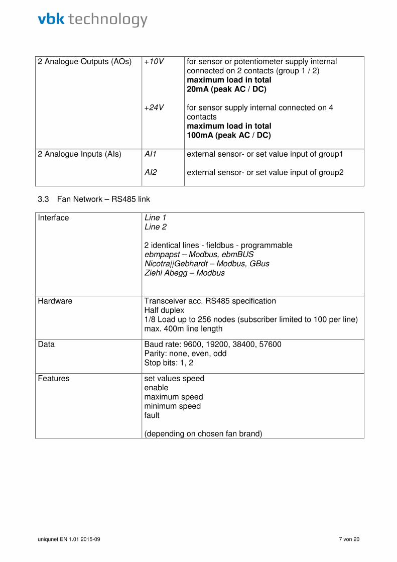
2 Analogue Outputs (AOs) +10V +24V
for sensor or potentiometer supply internal connected on 2 contacts (group 1 / 2) maximum load in total 20mA (peak AC / DC) for sensor supply internal connected on 4 contacts maximum load in total 100mA (peak AC / DC)
2 Analogue Inputs (AIs) AI1 AI2
external sensor- or set value input of group1 external sensor- or set value input of group2
3.3 Fan Network – RS485 link
Interface Line 1 Line 2 2 identical lines - fieldbus - programmable ebmpapst – Modbus, ebmBUS Nicotra||Gebhardt – Modbus, GBus Ziehl Abegg – Modbus
Hardware Transceiver acc. RS485 specification Half duplex 1/8 Load up to 256 nodes (subscriber limited to 100 per line) max. 400m line length
Data Baud rate: 9600, 19200, 38400, 57600 Parity: none, even, odd Stop bits: 1, 2
Features set values speed enable maximum speed minimum speed fault (depending on chosen fan brand)

vbk technology
uniqunet EN 1.01 2015-09 8 von 20
4 Installation
Warning
Installation of uniqunet by qualified personal only. This qualified personal must be familiar to these types of products and associated with danger and risks, authorized to install, mount, commission and use these types of product. Some parameters can cause a start of connected and powered fans, without any further confirmation required (scheduler, day/night shift …).
The device is fed be safety extra-low voltage (SELV) and matches to protection class III.
4.1 Ambient Operating Conditions
Devices of series uniqunet are designed and manufactured for indoor installation. Wall mounted variation have with closed lid IP 65 (environmental protection class). Devices in counter-sunk style rated as IP20, additional sealed, transparent lid available on request
Shock
Warning Do not drop the device or expose to sudden shock. Do not use the device in an area where it is likely to be exposed to constant vibration higher than 2,5 mm*s-1.
Temperature
Warning Do not use device outside temperature range of 0°C … 40°C
(32°F … 104°F)
Electromagnetic Radiation
Warning Do not use the device near sources of electromagnetic radiation.

vbk technology
uniqunet EN 1.01 2015-09 9 von 20
4.2 Mechanical Installation
Wall-Mounted Style
dimensions in mm drill pattern in mm
Counter-Sunk Style
required mounting section: 137x68 mm
16
0
166 106
72
144 122

vb
k te
ch
no
log
y
uniq
unet E
N 1
.01 2
015-0
9
10 vo
n 2
0
4.3
E
lectrica
l Insta
llatio
n
4.3
.1 C
onn
ectio
n O
vervie
w
Power Supply
error-relays day/night shift
Group 1 In-/Outputs
BUS Lines
USB Interface
+24
V
Error Relay 1
Error Relay 2
+24V
day/night
+24V
DI 1
AI 1
DI 2
AI 2
+10V
+24V
+10V
+24V
Net A
Net B
Net A
Net B
Lin
e 2
Lin
e 1
Group 2 In-/Outputs
Varia
tion
Co
un
ter S
un
k –
rear v
iew
Va
riatio
n W
all M
ou
nte
d –
fron
t vie
w te
rmin
al b
ox
Power Supply
Error-Relays Day/night shift
Group 1 In-/Outputs
BUS Lines
USB Interface
Group 2 In-/Outputs
vbk technology
uniqunet EN 1.01 2015-09 11 von 20
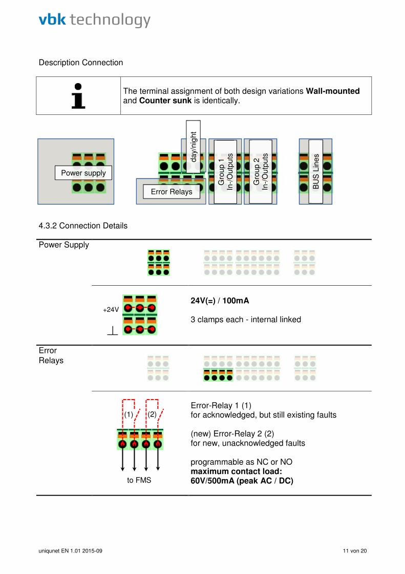
Description Connection
The terminal assignment of both design variations Wall-mounted and Counter sunk is identically.
4.3.2 Connection Details
Power Supply
24V(=) / 100mA 3 clamps each - internal linked
Error Relays
Error-Relay 1 (1) for acknowledged, but still existing faults (new) Error-Relay 2 (2) for new, unacknowledged faults programmable as NC or NO maximum contact load: 60V/500mA (peak AC / DC)
Power supply
Error Relays day/
nig
ht
Gro
up 1
In
-/O
utp
uts
Gro
up 2
In
-/O
utp
uts
BU
S L
ines
+24V
(1) (2)
to FMS

vbk technology
uniqunet EN 1.01 2015-09 12 von 20
Day/Night
Day/Night Shift Tripping +24V day/night
Group1 In-/Outputs
Group 1 DI1 (tripping +24V DI1) External enable of control group 1 AI1 (0 … 10V) analogue measure- or setpoint input +10V (Power Supply for Sensor / Potentiometer) maximum load in total (with Group 2) 20mA (peak AC / DC) +24V (Power Supply Sensor) maximum load in total (with Group 2) 100mA (peak AC / DC)
da
y/nig
ht
+24
V
+10
V
DI 1
AI 1
+
24
V
0…
10
VA
I 1
FMS
+24
V
∆p
0…
10
V
DI 1
+
24
V

vbk technology
uniqunet EN 1.01 2015-09 13 von 20
Group2 In-/Outputs
Group 2 DI1 (tripping +24V DI1) External enable of control group 2 AI1 (0 … 10V) analogue measure- or set point input +10V (Power Supply for Sensor / Potentiometer) maximum load in total (with Group 1) 20mA (peak AC / DC) +24V (Power Supply Sensor) maximum load in total (with Group 1) 100mA (peak AC / DC)
BUS Lines
Line 1 Connect up to 100 subscriber with RS485 Interface Line 2 Connect up to 100 subscriber with RS485 Interface WARNING! Handling of unused PINs according to specification of applied EC-fan supplier!
0…
10
V
+10
V
DI 2
AI 2
+
24
V
AI 2
DI 2
FMS
+24
V
∆p
0…
10
V
+24
V
Line 1
Line 2
Net A
Net B
Net A
Net B

vbk technology
uniqunet EN 1.01 2015-09 14 von 20
4.3.2 Connection Example Group 1 – closed loop control pressure 3 fans at line 1 Sensor signal ∆p as 0…10V and 24V(=) power supply Extern enable of closed loop controller by FMS
Group 2 – speed control by potentiometer 2 fans at line 2 Potentiometer for speed setting by 0…10V Internal enable of control
General connection day/night - shift – external timer Utilization error/new error by costumer FMS with external 24V (~) supply
enable controller by FMS
+24V
2x3 contacts Internally linked
Err
or
Rela
y 1
Err
or
Rela
y 2
da
y/nig
ht
+24
V
DI 1
AI 1
+
24
V
Net A
Net B
Net A
Net B
Linie 2
Linie 1
~
∆p
0…
10
V
+24
V
24V (~) 24V(=)
AI 2
+10
V
~ Set value by FMS
0…
10
V

vbk technology
uniqunet EN 1.01 2015-09 15 von 20
5 Working with uniqunet
5.1 Software
Display
Scan Line Network scan to find all connected devices with the
chosen protocol
Single Monitor Cyclic scan of single device and monitoring of requested data
Single Control
Control of a single addressable device with feedback
Group Control
Control of all fans assigned to one of 20 speed control groups
Broadcast
Control / Parameterizing of all connected devices without feedback (broadcast)
Group Building
up to 20 groups (free definition) for simple speed control and up to 2 groups for closed loop control mode
Internal PI-Controllers (2) two separate closed loop control circuits
free programmable as temperature, velocity, pressure and %
fixed assigned sensor signal inputs (1/2) and digital inputs (1/2) to each closed loop control group (1/2)
Error Output as error indication signal and free configurable signal outputs (high/low active) maximum 60V – 500mA Error 1 red for acknowledged, but still existing faults
Error 2 red alternating for new, unacknowledged faults
Operating Levels
3 operating levels (Monitor / Operator / Administrator)
Timer Programmable Scheduler for set-point shift of single fans and assigned groups

vbk technology
uniqunet EN 1.01 2015-09 16 von 20
5.2 Commissioning
5.2.1 Quick Commissioning – fan driven by speed setting required: Connection Power supply (24V) / Bus (NetA/NetB)
Mainmenu
Sublevel 1
Sublevel 2
Sublevel 3
1. „Login“ as Administrator default password „0000“
2. „Database“
used Bus Line (1/2) „Config Line“ choose relevant Bustyp
„Install Fan“
„Scan Line“ Found devices will be installed automatically – correct fan addressing required!
3. „Configuration“ choose – Single / Line / Group / All max. speed checked or set correctly
4. „Control“ choose – Single / Line / Group / All
„Speed Day“ set day speed in %
„Start Fan“ Start Control
5.2.2 Quick Commissioning – fan driven by closed loop control required: Connection Power supply (24V) / Bus (NetA/NetB) / Sensor AI (0…10V)
1. „Login“ as Administrator default password „0000“
2. „Database“
used Bus line (1/2) „Config Line“ choose relevant Bustyp
„Install Fan“
„Scan Line“ Found devices will be installed automatically – correct fan addressing required!
„Assign group“ assign (fan) group ( 1 …10) for closed loop control 0 = none group
3. „Configuration“ choose – Single / Line / Group / All max. speed checked or set correctly
4. „Controller“ choose – Single / Line / Group / All
„Config Controller“ choose Controller 1 or Controller 2 (acc. connection of sensor to AI1 or AI2)
„Group“ assign under #2 defined fan group to Controller if needed adapt further controller settings
„Control Controller“ choose Controller 1 or Controller 2
„Set Day“ Set Control value in %
„Start Controller“ Start Controller with “Day-setting”

vbk technology
uniqunet EN 1.01 2015-09 17 von 20
6 Technical Data Connection
Power Supply 24V (=)
Current Consumption maximum 100mA rating according load of 24V (=) i.e. by sensors
Connection plugs Serie Wire cross section
Wire cross section (AWG)
Cage Clamps Phoenix FMCD 1,5/ x-ST-3,5
min. 0,2mm2 / max. 1,5mm
2 (solid and stranded)
min. 0,25mm2 / max. 1,5mm
2 (stranded with ferrule without
plastic collar)
min. 0,25mm2 / max. 0,75mm
2 (stranded with ferrule with
plastic collar) min. AWG/kcmil 24 / max. AWG/kcmil 16
Housing
Variation
Wall-Mounted with lid Fibox Cardmaster PC 1716-l3TT
Counter-Sunk OKW NEG TYP A 144x72
Dimensions (LxBxH) 166 x 160 x 100mm
144 x 72 x 129nn
Weight appr. 700g
appr. 500g
Protection Class (DIN EN 60529)
IP65
IP20
Material
Polycarbonate (UL 94-5V)
Noryl (UL 94 V-0)
Protection Class (electrical) (DIN EN 61140)
III (Safety Extra Low Voltage) No Protective Earth
III (Safety Extra Low Voltage) No Protective Earth
Ambient Operating Conditions
usage indoor application
Temperature 0°C … 40°C (32 … 104°F) - Operating -20°C … 70°C (-4°F … 158°F) - Storage
relative humidity 0 … 90%, non-condensing

vbk technology
uniqunet EN 1.01 2015-09 18 von 20
IN/- and OUTPUTs
Digital Inputs DI (day/night; enable group)
+24V DI (Voltage) 10mA (minimum current source capacity) 4 kV (isolating voltage against internal circuit)
Analogue Inputs AI (Sensor values-, Speed setting)
0 … 0.5 … 10V (=) from 0.5V linear 40 kΩ (internal resistance) 3,75 kV (isolating voltage against internal circuit)
Digital Outputs DO (Error relays)
as low-active or high-active programmable 60V (max. Voltage as peak AC / DC) 500mA (max. Current as peak AC / DC) 1,5 kV (max. Current as peak AC / DC)
Analogue Outputs AO Sensor Power Supply
+10V (=) 20mA (max. Current as peak AC / DC) +24V (=) 100mA (max. Current as peak AC / DC) min 1kV (isolating voltage across DC/DC converter)
Fan Network
Hardware RS485
Maximum Subscriber 200 at 2 Lines (100 / Line)
Maximum line length 400m (per Line) Baud rate according type of subscriber cable (recommended) Cat. 5
isolating voltage against internal circuit
2,5 kV (overvoltage class 2)
0,5V
0,5V
Uanalogue
Uinp
10V
10V

vbk technology
uniqunet EN 1.01 2015-09 19 von 20
7 Additional Hints
7.1 Manufacturing
All devices of uniqunet series are manufactured according
DIRECTIVE 2011/65/EU on the restriction of the use of certain hazardous substances in electrical and electronic equipment
7.2 Packing and Shipping
The shipping is in fitting individual packing.
For Export uniqunet is categorized to the following HS code
85176200 Machines for the reception, conversion and transmission or regeneration of voice, images or other data, incl. switching and routing apparatus (excl. telephone sets, telephones for cellular networks or for other wireless networks)
All claims for damage must be reported immediately.
7.3 Service
Technical queries about uniqunet under:
vbk technology GmbH Verlängerte Goethestraße 9 08209 Auerbach
Tel.: +49 (0)3744 / 22 47 914 Fax: +49 (0)3744 / 22 35 595
[email protected] www.vbk-technology.de
