vbk-system vbk-s - pentairthermal.com · the vbk-system kit and vbk-s splice kit are for use with...
TRANSCRIPT

This component is an electrical device that must be installed correctly to ensure proper operation and to prevent shock or fire. Read these important warnings and carefully follow all of the installation instructions.• Tominimizethedangeroffirefromsustainedelectricalarcingifthe
heating cable is damaged or improperly installed, and to comply with the requirements of Pentair Thermal Management, agency certifications, and National Electrical Codes, ground-fault equipment protection must be used. Arcing may not be stopped by conventional circuit breakers.
• ComponentapprovalsandperformancearebasedontheuseofPentair Thermal Management-specified parts only. Do not use substitute parts or vinyl electrical tape.
• Theblackheatingcablecoreisconductiveandcanshort.Itmustbeproperly insulated and kept dry.
• Damagedbuswirescanoverheatorshort.Donotbreakbuswirestrands when scoring the jacket or fibers.
• Keepcomponentsandheatingcableendsdrybeforeandduringinstallation.
• Heatdamagedcomponentscanshort.Useaheatgunoratorchwithasoft,yellow,lowheatflame,notabluefocusedflame.Keeptheflamemoving to avoid overheating, blistering, or charring the heat-shrinkable tubes. Avoid heating other components. Replace any damaged parts.
HealtH Hazard: Overheating heat-shrinkable tubes will produce fumesthatmaycauseirritation.Useadequateventilationandavoidcharring or burning. Consult MSDS RAY3122 for further information.Uncuredsealantcanirritateeyes,noseandthroat.Readwarningsontube. Consult MSDS VEN0044 for additional information.
CHEMTREC24-houremergencytelephone: (800) 424-9300
Non-emergency health and safety information: (800) 545-6258.
WARNING: CAUTION:
1 / 14
VBK-SYSTEM VBK-SVLBTV Long-Line ConneCTion SySTem & SpLiCe KiT inSTaLLaTion inSTruCTionS
THERMAL MANAGEMENT SOLUTIONS EN-RaychemVBKsystem-IM-H55230 01/13
DEScRIpTIONThe VBK-SYSTEM Kit and VBK-S Splice Kit are for use with Raychem VLBTV2 heating cables connected to three-phase power. Materials for installing one system or one splice are included in each kit. The VL system is an engineered system that must be designed by Pentair Thermal Management.For additional information contact your Pentair Thermal Management representative or call (800) 545-6258.
TOOLS REqUIRED• Phillips screwdriver, no. 2 • Wire strippers• Diagonal cutters • Cabinet-tip screwdriver, 4.5 mm• Utility knife • Needle nose pliers• Heat gun or mini-torch • Channel-lock pliers, 12 inch
ADDITIONAL MATERIALS REqUIRED• Pipe straps
AppLIcATION INfORMATIONThe minimum installation temperature for the VBK-SYSTEM and the VBK-S Splice Kit is –40˚F (–40˚C). Kits are designed for above-ground use only.
ORIENTATION Of SySTEMThe diagrams below show correct (A) and incorrect (B, C and D) system orientations as follows:• A shows properly installed components. Note equal lengths and
correct orientation of each kit.• B shows Kit P2 rotated incorrectly.• C shows Kits P2 and P3 reversed incorrectly.• D shows unequal lengths between Kits P1, P2, P3 and E.Note: The splice kit is the only kit that may be placed at any distance between the other kits. The splice box is the only box that may be oriented in either direction.
Total circuit Length (L)
A)
B)
C)
D)
Correct
Incorrect
Incorrect
Incorrect
1/3 1/3 1/3
L? L? L?
KIT cONTENTS
VBK-SySTEM Kit contents
qty Description
1 P1 Power Connection Kit
1 P2 Phase Jumper Kit
1 P3 Phase Jumper Kit
1 E End Termination Kit
VBK-S Kit contents
qty Description
1 Splice Connection Kit
AppROVALS
-WS
Class I, Div. 2, Groups B, C, DClass II, Div. 2, Groups F, GClass III
Class I, Div. 2, Groups A, B, C, DClass II, Div. 2, Groups F, GClass III
Hazardous and Nonhazardous Locations
IMpORTANT: The VBK system and splice must be installed exactly as described in the sequence of instructions. The junction boxes and terminal blocks must be located and oriented correctly for the system to function properly.

THERMAL MANAGEMENT SOLUTIONS EN-RaychemVBKsystem-IM-H55230 01/13 2 / 14
A
B
Typical System Layout(with P2 box exploded for illustration)
Typical Wiring Diagrams for 480 V and 600 V Systems(600 V Systems in United States only)
conduit drain is recommended but not shown.

3 / 14THERMAL MANAGEMENT SOLUTIONS EN-RaychemVBKsystem-IM-H55230 01/13
c
D
Heating cable Type:VLBTV2-cRVLBTV2-cT
Heating cable construction
Wiring Diagram
IMpORTANT: Refer to wiring naming conventions when connecting the heating cable leads to the terminal rail assemblies.
THERMAL MANAGEMENT SOLUTIONS EN-RaychemVBKsystem-IM-H55230 01/13 4 / 14
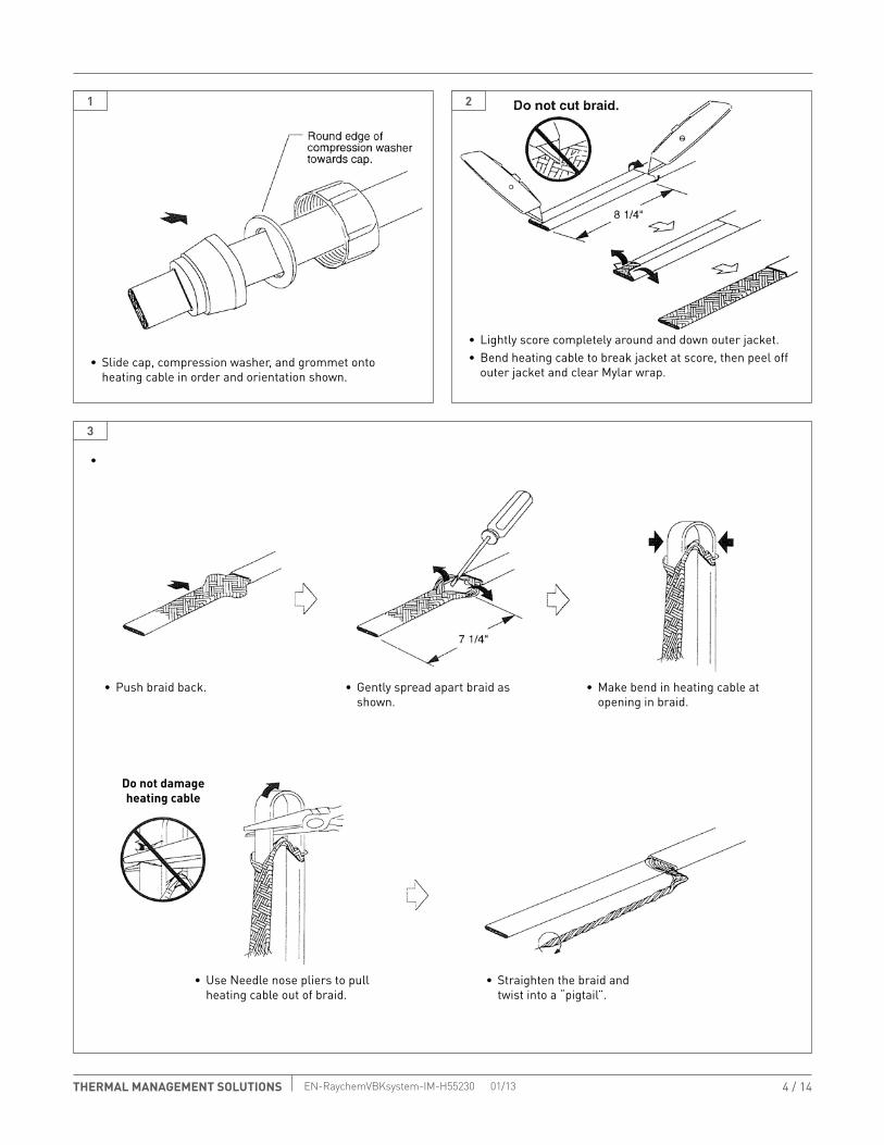
1
3
2
• Slide cap, compression washer, and grommet onto heating cable in order and orientation shown.
•
• Lightly score completely around and down outer jacket.• Bend heating cable to break jacket at score, then peel off
outer jacket and clear Mylar wrap.
• Push braid back.
• Use Needle nose pliers to pull heating cable out of braid.
• Gently spread apart braid as shown.
• Straighten the braid and twist into a “pigtail”.
• Make bend in heating cable at opening in braid.
Do not damage heating cable

5 / 14THERMAL MANAGEMENT SOLUTIONS EN-RaychemVBKsystem-IM-H55230 01/13
4
5
• On each side of heating-cable section, lightly score across then down inner jacket as shown. Do not score completely around heating cable.
• Use diagonal cutters to trim away jacket on each side of heating cable.
• Bend heating cable to break jacket at score, then peel back inner jacket.
• Remove 1/2 in of insulation from end of white, red, and black wires.
Do not cut wire strands.
Do not cut wires.

THERMAL MANAGEMENT SOLUTIONS EN-RaychemVBKsystem-IM-H55230 01/13 6 / 14
6
7
8
• Trim braid and bus wires.
• Score core between bus wires 3/4 in from inner jacket.• Bend core to break at score.
• Twist back and peel bus wire from core.
• Notch core at the end.
• Slide on heat-shrinkable tubes. Place red tube on bus wire next to red wire, black tube on bus wire next to black wire, and yellow/green tube on the braid. Use a heat gun or minitorch with a soft yellow flame to shrink the tubes completely.
• Peel core and any remaining material from bus wires.
Do not cut bus wires.

7 / 14THERMAL MANAGEMENT SOLUTIONS EN-RaychemVBKsystem-IM-H55230 01/13
Cover exposed core
1/2”
Clear yellowtube 1” long
RTV
Silicone R
ubber
Adhesive
Sealant
D1"
D
D = 3" for P1 KitD = 1" for P2, P3, E and S Kits
Total circuit Length (L)
A)
B)
C)
D)
Correct
Incorrect
Incorrect
Incorrect
1/3 1/3 1/3
L? L? L?
9
10
11
• Center clear yellow tube over end of core.• Heat tube until it shrinks completely and adhesive flows
out ends.• While adhesive is still hot, pinch between bus wires and
hold for 5 seconds to create a seal.
• Wrap black cloth tape tightly around heating cable to cover exposed conductive core.
• Position grommet as indicated for “D” above. Then slide the grommet one inch further in direction away from end of heating cable as shown. Apply silicone adhesive to the 1 in zone around the heater.
• Slide the grommet back to the “D” location. Apply additional RTV silicone to fill voids for a watertight seal.
for p2, p3, and S Kits repeat Steps 1 through 10 for second heating cable.
ORIENTATION Of SySTEMThe diagrams show correct (A) and incorrect (B, C and D) system orientations as follows:• A shows properly installed components. Note equal lengths
and correct orientation of each kit.• B shows Kit P2 rotated incorrectly.• C shows Kits P2 and P3 reversed incorrectly.• D shows unequal lengths between Kits P1, P2, P3 and E.Note: The VBK-S Splice Kit is the only kit that may be placed at any distance between the other kits. The splice box is the only box that may be oriented in either direction.
IMpORTANT: For best adhesion, keep the cable warm. The tape will not adhere well at temperatures approaching -20°F (-29°C).
cAUTION: Health Hazard Uncured sealant can irritate eyes, nose and throat. Refer to Material Safety Data Sheet VEN0044 for more information.
IMpORTANT: The VL System P1, P2, P3 and E Kits must be installed as shown in diagram at right. The connection boxes and terminal blocks must be located and oriented correctly for the system to function properly.

THERMAL MANAGEMENT SOLUTIONS EN-RaychemVBKsystem-IM-H55230 01/13 8 / 14
12
13
for VBK-p1 Kit
for VBK-p1 Kit
• Wiring diagram in box will have VL-p1 KIT printed on the upper right corner. Make sure diagram matches kit to be installed.
• Connect supply conductors (following usual practices) to terminals identified on the box wiring diagram. Also refer to diagram “D” in Step 11. Use a 4.5 mm cabinet-tip screwdriver to tighten terminal block screws.
• Connect bus wires identified as HEATER RED and HEATER BLACK and the RED, WHITE, and BLACK wires to terminals identified on box wiring diagram. Connect the pigtailed braid to the BRAID terminal as shown on the diagram.
• Use a conduit drain to prevent condensation and water build-up inside the VBK-P1 Kit.• Go to Step 22 to complete the VBK-P1 installation.
• Mount legs to junction box using fasteners provided. • Slide compression washer up to grommet. Locate compression washer slot over grommet.
• Thread cap on elbow assembly. Use 12 in channel-lock pliers to tighten cap securely in place. Important: Do not allow heating cable to rotate when tightening cap and do not cross the threads.
• Secure box assembly to pipe using a steel strap. check Step 11 for correct location and orientation of VBK-p1 Kit on pipe.
• Feed prepared heating cable through 90° elbow assembly. Position grommet in hub attached to elbow.

9 / 14THERMAL MANAGEMENT SOLUTIONS EN-RaychemVBKsystem-IM-H55230 01/13
14
15
for VBK-p2 Kit
for VBK-p2 Kit
• Wiring diagram in box will have VL-p2 KIT printed on the upper right corner. Make sure diagram matches kit to be installed.
• Connect bus wires identified as HEATER RED and HEATER BLACK and the RED, WHITE, and BLACK wires to terminals identified on box wiring diagram. Connect the pigtailed braid to the BRAID terminal as shown on the diagram. Use a 4.5 mm cabinet-tip screwdriver to tighten terminal block screws.
• Go to Step 22 to complete the VBK-P2 installation.
• Mount low-profile bracket to junction box using fasteners provided.
• Feed prepared heating cable through hub. Position grommet in hub. Slide compression washer up to grommet. Locate compression washer slot over grommet.
• Thread cap on hub. Use 12 in channel-lock pliers to tighten cap securely in place. Important: Do not rotate heating cable when tightening cap and do not cross the threads.
• Repeat for the second heating cable.• Secure box assembly to pipe using a steel strap. check
Step 11 for correct location and orientation of VBK-p2 Kit on pipe.

THERMAL MANAGEMENT SOLUTIONS EN-RaychemVBKsystem-IM-H55230 01/13 10 / 14
16
17
for VBK-p3 Kit
for VBK-p3 Kit
• Wiring diagram in box will have VL-p3 KIT printed on the upper right corner. Make sure diagram matches kit to be installed.
• Connect bus wires identified as HEATER RED and HEATER BLACK and the RED, WHITE, and BLACK wires to terminals identified on box wiring diagram. Connect the pigtailed braid to the BRAID terminal as shown on the diagram. Use a 4.5 mm cabinet-tip screwdriver to tighten terminal block screws.
• Go to Step 22 to complete the VBK-P3 installation.
• Mount low-profile bracket to junction box using fasteners provided.
• Feed prepared heating cable through hub. Position grommet in hub. Slide compression washer up to grommet. Locate compression washer slot over grommet.
• Thread cap on hub. Use 12 in channel-lock pliers to tighten cap securely in place. Important: Do not rotate heating cable when tightening cap and do not cross the threads.
• Repeat for the second heating cable.• Secure box assembly to pipe using a steel strap. check
Step 11 for correct location and orientation of VBK-p3 Kit on pipe.

11 / 14THERMAL MANAGEMENT SOLUTIONS EN-RaychemVBKsystem-IM-H55230 01/13
18
19
for VBK-E Kit
for VBK-E Kit
• Wiring diagram in box will have VL-E KIT printed on the upper right corner. Make sure diagram matches kit to be installed.
• Connect bus wires identified as HEATER RED and HEATER BLACK and the RED, WHITE, and BLACK wires to terminals identified on box wiring diagram. Connect the pigtailed braid to the BRAID terminal as shown on the diagram. Use a 4.5 mm cabinet-tip screwdriver to tighten terminal block screws.
• Go to Step 22 to complete the VBK-E installation.
• Mount low-profile bracket to junction box using fasteners provided.
• Feed prepared heating cable through hub. Position grommet in hub. Slide compression washer up to grommet. Locate compression washer slot over grommet.
• Thread cap on hub. Use 12 in channel-lock pliers to tighten cap securely in place. Important: Do not rotate heating cable when tightening cap and do not cross the threads.
• Secure box assembly to pipe using a steel strap. check Step 11 for correct location and orientation of VBK-E Kit on pipe.

THERMAL MANAGEMENT SOLUTIONS EN-RaychemVBKsystem-IM-H55230 01/13 12 / 14
20
21
for VBK-S Kit
for VBK-S Kit
• Wiring diagram in box will have VL-S KIT printed on the upper right corner. Make sure diagram matches kit to be installed.
• Connect bus wires identified as HEATER RED and HEATER BLACK and the RED, WHITE, and BLACK wires to terminals identified on box wiring diagram. Connect the pigtailed braid to the BRAID terminal as shown on the diagram. Use a 4.5 mm cabinet-tip screwdriver to tighten terminal block screws.
• Go to Step 22 to complete the VBK-S installation.
• Mount low-profile bracket to junction box using fasteners provided.
• Feed prepared heating cable through hub. Position grommet in hub. Slide compression washer up to grommet. Locate compression washer slot over grommet.
• Thread cap on hub. Use 12 in channel-lock pliers to tighten cap securely in place. Important: Do not rotate heating cable when tightening cap and do not cross the threads.
• Repeat for the second heating cable.• Secure box assembly to pipe using a steel strap. check
Step 11 for correct location and orientation of VBK-S Kit on pipe.
13 / 14THERMAL MANAGEMENT SOLUTIONS EN-RaychemVBKsystem-IM-H55230 01/13
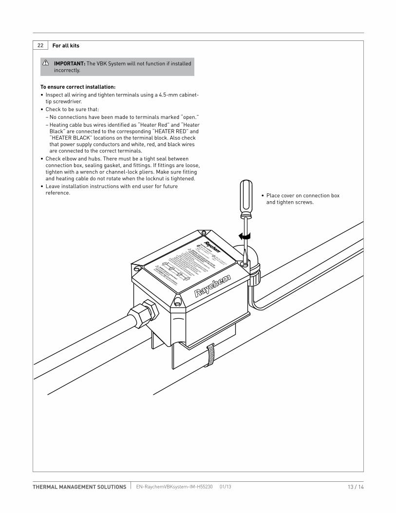
22 for all kits
To ensure correct installation:• Inspect all wiring and tighten terminals using a 4.5-mm cabinet-
tip screwdriver.• Check to be sure that:
– No connections have been made to terminals marked “open.”– Heating cable bus wires identified as “Heater Red” and “Heater
Black” are connected to the corresponding “HEATER RED” and “HEATER BLACK” locations on the terminal block. Also check that power supply conductors and white, red, and black wires are connected to the correct terminals.
• Check elbow and hubs. There must be a tight seal between connection box, sealing gasket, and fittings. If fittings are loose, tighten with a wrench or channel-lock pliers. Make sure fitting and heating cable do not rotate when the locknut is tightened.
• Leave installation instructions with end user for future reference. • Place cover on connection box
and tighten screws.
IMpORTANT: The VBK System will not function if installed incorrectly.

14 / 14THERMAL MANAGEMENT SOLUTIONS EN-RaychemVBKsystem-IM-H55230 01/13
WWW.tHerMal.PeNtaIr.COM
© 2010-2013 Pentair. PN 566607-000
NOrtH aMerICaTel: +1.800.545.6258Fax: +1.800.527.5703Tel: +1.650.216.1526Fax: [email protected]
eurOPe, MIddle east, afrICaTel: +32.16.213.511Fax: [email protected]
asIa PaCIfICTel: +86.21.2412.1688Fax: [email protected]
latIN aMerICaTel: +55.11.2588.1400Fax: [email protected]
Pentair is owned by Pentair or its global affiliates. All other trademarks are the property of their respective owners. Pentair reserves the right to change specifications without prior notice.