universiti tun hussein onn malaysia status...
TRANSCRIPT

UNIVERSITI TUN HUSSEIN ONN MALAYSIA
STATUS CONFIRMATION FOR MASTER’S THESIS
PERFORMANCE EVALUATION OF PEGASIS AND LEACH PROTOCOL
USING MATLAB BASED SIMULATION PLATFORM
ACADEMIC SESSION : 2015/2016
I, NAZIHAN BINTI AZIZIUDDIN agree to allow this Master’s Project Report to be kept at the
Library under the following terms:
1. This Master’s Project Report is the property of the Universiti Tun Hussein Onn Malaysia.
2. The library has the right to make copies for educational purposes only.
3. The library is allowed to make copies of this report for educational exchange between higher
educational institutions.
4. ** Please Mark ()
CONFIDENTIAL (Contains information of high security or of great
importance to Malaysia as STIPULATED under the
OFFICIAL SECRET ACT 1972)
RESTRICTED (Contains restricted information as determined by the
organization/ institution where research was conducted)
FREE ACCESS
Approved by,
__________________________________ __________________________________
(WRITER’S SIGNATURE) (SUPERVISOR’S SIGNATURE)
Permanent Address: Supervisor’s Name
BT 15 ½, ASSOC. PROF DR. JIWA BIN ABDULLAH
KG AIR LANJUT,
78000 ALOR GAJAH,
MELAKA.
Date: Date:
NOTE:
** If this Master’s Thesis is classified as CONFIDENTIAL or RESTRICTED, please
attach the letter from the relevant authority/organization stating reasons and duration
for such classifications.

“I hereby declare that I have read this project thesis and in my opinion this project thesis
is in term of content and quality requirements fulfils the purpose for the award of the
Degree of Master in Electrical Engineering with Honours”.
Signature : …………………………………………………………..……
Supervisor : ASSOCIATE PROF DR. JIWA BIN ABDULLAH
Date : ………………………………………………………..………

PERFORMANCE EVALUATION OF PEGASIS AND LEACH PROTOCOL USING
MATLAB BASED SIMULATION PLATFORM
NAZIHAN BINTI AZIZIUDDIN
A project report submitted in partial
fulfillment of the requirement for the award of the
Degree of Master of Electrical Engineering
Faculty of Electrical and Electronics Engineering
Universiti Tun Hussein Onn Malaysia
JANUARY 2016

ii
I hereby declare that the work in this project is my own except quotation and summaries
which have been duly acknowledge
Signature : …………………………………………………………….…
Student : NAZIHAN BINTI AZIZIUDDIN
Date : …………………………………………………………….…
Signature : …………………………………………………………..……
Supervisor : ASSOCIATE PROF DR. JIWA BIN ABDULLAH
Date : ………………………………………………………..………

iii
For my beloved mother, father, brothers, sisters, supervisor, lecturers and friends
For your infinite and unfading love, patience, guidance and advice I might not had this
kind of achievement

iv
ACKNOWLEDGEMENT
Alhamdulillah, all praises to Allah for the strengths and His blessing of mind and health
in completing this report and my master degree study. Special appreciation goes to my
supervisor, Prof. Madya Dr Jiwa Bin Abdullah, for his supervision and constant support.
His invaluable help of constructive comments and suggestion throughout the research
works have contributed to the success of this research. I would like to express my great
and sincere respects to my beloved parents; Mr Aziziuddin Bin Abd Aziz and Mrs.
Maimunah Binti Abu for their endless love, prayers and encouragement. I would also
like to convey my appreciation to my fellow friends. Finally, yet importantly, for those
who directly or indirectly involved with this thesis. Thank you very much.

v
ABSTRACT
Wireless sensor networks (WSNs) consist of thousands of tiny nodes having the
capability of sensing, computing, wireless communications, and variety of application
scenarios including medical application, military, home security and so on. Many
routing, power management, and data dissemination protocols have been specifically
designed for WSNs where energy consumption is an essential design issues. Energy is a
critical resource in WSNs and system lifetime needs to be prolonged through the use of
energy-aware strategies during system operation. Routing in WSN is very challenging
due to the inherent characteristics that distinguish these networks from other wireless
network like mobile ad hoc networks or cellular networks. Many routing protocols have
been specifically designed for WSN. This thesis is focus on the performance of two
hierarchical routing which is LEACH and PEGASIS in terms of energy consumption,
system lifetime and time taken to complete the rounds. The simulation experiments are
done by using network simulator produce in MATLAB. From the results it can be
deduced, that the PEGASIS gives a better performance in terms of energy dissipation
and network lifetime compare to LEACH.

vi
ABSTRAK
Rangkaian Sensor Tanpa Wayar (WSN) terdiri daripada beribu-ribu nod kecil yang
mempunyai kebolehan untuk mengesan, pengkomputeran, komunikasi tanpa wayar, dan
pelbagai aplikasi meliputi aplikasi bidang perubatan, ketenteraan, keselamatan rumah
dan sebagainya. Perkara penting dalam pembinaan WSN adalah penggunaan tenaga di
mana laluan, pengurusan tenaga dan penyebaran data protokol direa khas dalam
pembinaan WSN. Semasa sistem beroperasi, tenaga adalah sumber yang penting dalam
WSN dan untuk memanjangkan jangka hayat rangkaian perlu melalui penggunaan
strategi tenaga sedar. Penghalaan dalam WSN adalah mencabar kerana ciri-ciri yang
wujud yang membezakan rangkaian ini daripada rangkaian tanpa wayar yang lain seperti
rangkaian mudah alih ad hoc atau rangkaian selular. Banyak protokol telah direka khas
untuk WSN. Kajian ini akan tertumpu kepada prestasi penggunaan tenaga, jangka hayat
system dan masa yang di ambil untuk melengkapkan pusingan oleh dua protocol yang
berasaskan hierarki konsep iaitu LEACH dan PEGASIS. Simulasi ini dilakukan dengan
menggunakan rangkaian yang direka menggunakan perisian MATLAB. Daripada
keputusan ini dapat dirumuskan bahawa PEGASIS menunjukkan prestasi yang lebih
baik dari segi perlepasan tenaga dan jangka hayat berbanding LEACH.

vii
CONTENTS
TITLE i
DECLARATION ii
DEDICATION iii
ACKNOWLEDGEMENT iv
ABSTRACT v
ABSTRAK vi
CONTENTS vii
LIST OF TABLES x i
LIST OF FIGURES xii
LIST OF SYMBOLS AND ABBREVIATIONS xiv
CHAPTER 1 INTRODUCTION 1
1.1 Project Background 1
1.2 Problem Statement 2
1.3 Objectives 3
1.4 Project Scopes 3
1.5 Thesis Structure Outline 4
CHAPTER 2 LITERATURE REVIEW 5
2.1 Wireless Sensor Networks (WSN) 5
2.1.1 Overview of WSNs 5

viii
2.1.2 A wireless sensor network model 6
2.1.3 Sensor node architecture 7
2.1.4 Wireless sensor networks application 9
2.2 Network Characteristics and design objectives 9
2.2.1 Network characteristics 9
2.2.2 Network design objectives 10
2.2.3 Network design challenges and routing issues 12
2.3 Wireless sensor network logical topologies 13
2.3.1 Cluster logical topology 13
2.3.1.1 Cluster types 14
2.3.2 Flat logical topology 14
2.3.3 Chain logical topology 16
2.4 Routing protocols in WSN 16
2.4.1 LEACH Protocol 18
2.4.1.1 LEACH Architecture 19
2.4.1.2 Cluster Head (CH) Selection 20
2.4.1.3 Cluster set-up phase 21
2.4.1.4 Steady state operation 23
2.4.2 PEGASIS protocol 24
2.4.2.1 Leader selection 26
2.4.2.2 Data transmission 27
2.5 Review of evaluation criteria 28
2.5.1 Evaluation measures related to energy usage 28
2.5.2 Evaluation measures related to the lifetime
of the network 29
2.5.3 Evaluation measures related to the time
Requirement to completing round 30
2.6 Wireless sensor network simulation tool 31
2.6.1 Network simulator NS-2 32
2.6.2 TOSSIM 32

ix
2.6.3 OPNET 33
2.6.4 OMNeT++ 33
2.6.5 MATLAB 34
2.6.7 PROWLER 34
2.7 Related work 29
2.8 Chapter summary 37
CHAPTER 3 METHODOLOGY 38
3.1 Project flowchart 38
3.2 System design 40
3.3 Implementation of LEACH algorithm 42
3.4 Implementation of PEGASIS algorithm 43
3.5 Performance metrics 46
3.5.1 Evaluation measures related to overall
Energy consumption 46
3.5.2 Evaluation measures related to network
Lifetime 46
3.5.3 Evaluation measures related to time
requirement comparison for completing round 47
3.6 Simulation and analysis tools 48
3.7 Radio Model 49
3.8 Chapter summary 50
CHAPTER 4 RESULTS AND DATA ANALYSIS 51
4.1 Simulation on the MATLAB (LEACH protocol) 51
4.2 Simulation on the MATLAB (PEGASIS protocol) 53
4.3 Performance evaluation 54
4.3.1 Energy consumption 54
4.3.2 System lifetime 57
4.3.3 Performance comparison for LEACH
and PEGASIS protocol 60

x
4.4 Chapter summary 62
CHAPTER 5 CONCLUSION AND FUTURE WORKS 63
5.1 Conclusion 63
5.2 Future work 64
REFERENCES 65
APPENDIX 69
VITA 80

xi
LIST OF TABLES
2.1 Routing protocols for WSNs 17
2.2 Summary of related works 36
3.1 Equipment’s and tool features 48
4.1 system parameter value for PEGASIS 53
4.2 Sum of remaining energy of nodes per number of rounds 56
4.3 Performance result for a 50m x 50m network 57
4.4 Performance result for a 100m x 100m network 57

xii
LIST OF FIGURES
2.1 Wireless sensor network architecture 7
2.2 Typical components of a sensor node 7
2.3 Cluster-based topology architecture 14
2.4 Flat topology architecture 15
2.5 Chain logical topology 16
2.6 LEACH protocol 18
2.7 Time line showing operation of LEACH 19
2.8 Flowchart of the distributed cluster formation algorithm 22
2.9 Flowchart of the steady-state operation for LEACH 24
2.10 Example of PEGASIS chain 25
2.11 Hierarchical PEGASIS protocol algorithm 27
2.12 PEGASIS’s data gathering 28
3.1 Project flowchart 39
3.2 Crteate a new script 40
3.3 Editor window 41
3.4 Run the simulation 41
3.5 Flowchart of LEACH protocol 42
3.6 Flowchart of PEGASIS protocol 45
3.7 First order radio model 49
4.1 Network topology 52
4.2 Dead node 52
4.3 Chain construction in PEGASIS protocol 53
4.4 Number of packet sent to BS, Number of dead node and
Sum of energy of nodes with area size m x m (LEACH protocol) 55
4.5 Sum of energy of nodes vs. Number of rounds in
xiii
LEACH protocol 55
4.6 Sum of energy of nodes vs. Number of rounds in
PEGASIS protocol 56
4.7 Performance result for a 50m x 50m network size
with initial energy 0.25J 58
4.8 Performance result for a 50m x 50m network size
with initial energy 0.5J 59
4.9 Lifetime pattern of a randomly deployed 100 node
sensor network 60
4.10 Comparative analysis of sum of remaining energy in
Node vs. Number of rounds 61
4.11 Time requirement comparison for completing rounds 62

xiv
LIST OF SYMBOLS AND ABBREVIATIONS
WSNs - Wireless Sensor Networks
LEACH - Low-Energy Adaptive Clustering Hierarchy
PEGASIS - Power-Efficient Gathering in Sensor Information Systems
GUI - Graphical User Interface
BS - Base Station
ADC - Analog Digital Converter
RAM - Random Access Memory
EEPROM - Electrically Erasable Programmable Read-Only Memory
RF - Radio Frequency
MANET - Mobile Ad Hoc Network
QoS - Quality-of-Service
SN - Sensor Node
CH - Cluster Head
MECN - Minimum Energy Communication Network
SMECN - Small Minimum Energy Communication Network
GAF - Geographic Adaptive Fidelity
GEAR - Geographical and Energy Aware Routing
TBF - Trajectory-Based Forwarding
BVGF - Bounded Voronoi Greedy Forwarding
GeRaF - Geographic Random Forwarding
ACQUIRED - ACtive QUery forwarding In sensoR nEtworks
EAD - Energy Aware Data

xv
TEEN - Threshold Sensitive Energy Efficient sensor Network
CADR - Chain Anisotropic Diffusion Routing
SNR - Signal-to-noise Ratio
OTCL - Object Tool Command Language
NAM - Network AniMator
PROWLER - Probabilistic Wireless Network Simulator
TDMA - Time division multiple access
DSSS - direct-sequence spread spectrum
𝐸𝑎𝑚𝑝 - transmitter amplifier
𝐸𝑇𝑥 - Energy model for the transmitter
𝐸𝑅𝑥 - Energy model of the receiver
E[𝐸𝑤 ] - expected wasted energy
𝑃𝑟𝑒𝑐 ,𝑖𝑑𝑒𝑎𝑙 - Ideal reception signal strength
𝐸𝑒𝑙𝑒𝑐 - Radio electronic
p - desired percentage of cluster heads
r - current round
G - set of nodes
J - Joule
m - Meter
λ - Wavelength of the carrier signal
𝑃𝑟(𝑑) - Receiver power given a transmitter-receiver separation of d
𝑃𝑡 - Transmit power
𝐺𝑡 - Gain of the transmitting antenna
𝐺𝑟 - Gain of the receiving antenna
𝐸𝑇𝑥 - Energy model for the transmitter
𝐸𝑅𝑥 - Energy model for the receiver
𝐸𝐶𝐻 - Energy dissipated in cluster-head node during a single frame

1
CHAPTER 1
INTRODUCTION
1.1 Project Background
Wireless Sensor Network (WSN) is a very large array of diverse sensor nodes that are
interconnected by a communication network. The elementary components of a sensor
node are sensing unit, a processing unit, a transceiver unit and a power unit. The sensor
node senses the physical quantity being measured and coverts it into an electrical signal.
Then, the signal is fed to an A/D converter and is ready to be used by the processor
(Parminder, K. et al, 2012).
The processor will convert the signal into data depending on how it is
programmed and it sends the information to the network by using a transceiver. The
sensing data are shared between the sensor nodes and are used as input for a distributed
estimation system (Akkaya & Younis, 2004) (Heinzelman, Chandrakasan &
Balakrishnan, 2000).
The fundamental characteristics of WSN are reliability, accuracy, flexibility, cost
effectiveness, and ease of deployment (Akkaya & Younis, 2004). As we know that
wireless sensor network mainly consists of tiny sensor node which is equipped with a
limited power source. The lifespan of an energy-constrained sensor is determined by
how fast the sensor consumes energy.

2
A node in the network is no longer useful when its battery dies. Researchers are
now developing new routing mechanisms for sensor networks to save energy and pro-
long the sensor lifespan. The dynamic clustering protocol allows us to space out the
lifespan of the nodes, allowing it to do only the minimum work it needs to transmit data
(Akyildiz, Su, Sankarasubramaniam & Cayirci, 2002).
The WSN can be applied to a wide range of applications, such as environment
management, environmental monitoring, industrial sensing, infrastructure protection,
battlefield awareness and temperature sensing. So, it is essential to improve the energy
efficiency to enhance the quality of application service (Akyildiz, Su,
Sankarasubramaniam & Cayirci, 2002) (Sabarish, Moorthy, Dhivya & Sakthi, 2012).
1.2 Problem Statement
There are various problems in Wireless sensor network. Coverage problem, which
reflects how well a sensor network is monitored or tracked by sensors. Position
estimation problem, which relates to the distance measured between sensor positions. In
addition, one of the fundamental issues is energy conservation of sensors, system
lifetime and throughput. Incidentally, the energy consumption can be correlated to the
quantity of packets sent and received. In Wireless sensor networks, most of the energy is
consumed in transmission and receiving of data as compared to sensing and processing
of data (Rahman & Anwar (2013). Sensor nodes are severely constrained by the amount
of battery power available, limiting the lifetime and quality of the network. Since
wireless network communications consume significant amount of battery power, sensor
nodes should spend as little energy as possible receiving and transmitting data.
Therefore, it is desirable that the network protocol should take care of issues like energy-
efficiency, system lifetime and delay. Thus, this project is to investigate the suitable
network protocol used such as LEACH and PEGASIS that will give the best
performance in the wireless sensor network. In this research, both protocols are
compared to distinguish the performance of those networks in terms of energy

3
consumption of randomly deployed node, network lifetime pattern and time requirement
comparison for completing a round.
1.3 Objectives
The objectives of this project are:
1. To study about LEACH and PEGASIS protocol in wireless sensor networks.
2. To investigate and analyze the performance of LEACH and PEGASIS
protocol in wireless sensor network.
3. To compare the performance of LEACH and PEGASIS protocol.
1.4 Project Scopes
This project focuses on the scopes below to fulfill the objectives of the project, which
represent as follows:
i. Study about hierarchical cluster-based routing schemes and algorithms
but focusing in LEACH and PEGASIS protocol.
ii. This algorithm will be simulated and verified using MATLAB. The
quantitative analysis and performance evaluation for LEACH and
PEGASIS protocol will be done.
iii. The performance comparison between LEACH and PEGASIS protocol
using the parameters that will be informed such as, number of round,
network size, initial energy and location of BS.
4
iv. The performance comparison of LEACH and PEGASIS protocol are
energy consumption, network lifetime and time requirement comparison
for completing rounds.
1.5 Thesis structure outline
This thesis consists of five chapters that will elaborate more about this research.
Chapter one consists of the background of the project. In addition, it will discuss
about the problem statement, objectives of the project, project scopes and thesis
structure outline.
Chapter two discusses literature review that consist of the explanation about
WSNs, network characteristics and design, routing protocols for LEACH and PEGASIS,
energy radio model, the application of WSNs and limitation. In addition, the simulation
program that familiar with WSNs.
Chapter three consists of the design methodology of the project. The design
overview and block diagram will also be discussed. In addition, the flowchart of the
protocol used and the system assumption is presented.
Chapter four present the simulation and the results for the research of LEACH
and PEGASIS protocols. This section will notify the measurement tools to fulfill the
objectives of this project. In addition, for this chapter also discuss the parameters of the
simulation which network size, initial energy, numbers of nodes and radio model used.
For the last chapter which is Chapter five is the conclusion and suggestion for
future work. All the result from previous chapter was summarized in this chapter.

5
CHAPTER 2
LITERATURE REVIEW
2.1 Wireless Sensor Networks (WSN)
2.1.1 Overview of WSNs
Wireless sensor network (WSN) is widely considered as one of the most important
technologies for the twenty-first century. In the past decades, it has received tremendous
attention from both academia and industry all over the world. A WSN typically consists
of a large number of low-cost, low-power, and multifunctional wireless sensor nodes,
with sensing, wireless communications and computation capabilities (S.K. Singh, 2010).
These sensor nodes communicate over short distance via a wireless medium and
collaborate to accomplish a common task, for example, environment monitoring,
military surveillance, and industrial process control (Jun & Abbas, 2009) The basic
philosophy behind WSNs is that, while the capability of each individual sensor node is
limited, the aggregate power of the entire network is sufficient for the required mission.
In many WSN applications, the deployment of sensor nodes is performed in an
ad hoc fashion without careful planning and engineering. Once deployed, the sensor
nodes must be able to autonomously organize themselves into a wireless communication
network. Sensor nodes are battery-powered and are expected to operate without
6
attendance for a relatively long period of time. In most cases it is very difficult and even
impossible to change or recharge batteries for the sensor nodes. WSNs are characterized
with denser levels of sensor node deployment, higher unreliability of sensor nodes, and
sever power, computation, and memory constraints. Thus, the unique characteristics and
constraints present many new challenges for the development and application of WSNs.
Due to the severe energy constraints of large number of densely deployed sensor
nodes, it requires a suite of network protocols to implement various network control and
management functions such as synchronization, node localization, and network security.
The traditional routing protocols have several shortcomings when applied to WSNs,
which are mainly due to the energy-constrained nature of such networks (Jun & Abbas,
2009).
2.1.2 A wireless sensor network model
WSNs architecture shown in Figure 2.1 consists of a set of many sensors with sensing,
wireless communication and computational capabilities. These sensors are scattered in
the preserved environment and located far from users. The architecture of WSNs
includes three entities are (Karl & Willing, 2005):
Sensors which make up the network: its function is based on taking local
measures through a discrete system, creating a wireless network in an unattended
environment, gathering data and sending them to the final user through Base
Station (BS).
Base station or gateway node: it is located near the sensor field. The data or
information gathered by the sensor field is sent to the base station through a
multihop infrastructure less architecture, which communicates with the user via
internet or satellite communication.
User: it is the entity interested in obtaining the information about a specific
phenomenon by means of measuring or monitoring the environment.

7
Figure 2.1: Wireless sensor network architecture
2.1.3 Sensor node architecture
A sensor node is a small device that has a micro-sensor technology, low power signal
processing, low power computation and a short-range communication capability. A
typical sensor node consists of four basic components which are sensing unit, processing
unit (microcontroller), transceiver unit and power unit (Sabarish, 2012) as shown in
Figure 2.2.
Figure 2.2: Typical components of a sensor node

8
Descriptions of the basic components are given as below:
Sensing Unit: A sensor is a device that measures some physical quantity and converts it
into a signal to be processed by the microcontroller. A wide range of sensor types exists,
including thermal, acoustic, visual, infrared and magnetic. Sensors may be passive
(sensing without active manipulation of the environment) or active (using active
manipulation/probing of the environment to sense data) and may be directional or
unidirectional. The sensing unit senses and converts the signal from analog to digital via
the Analog Digital Converter (ADC), location finding systems, mobilizes that are
required to move the node in specific applications and power generators. The analog
signals are measured by the sensors are measured by the sensors are digitized via an
ADC and in turn fed into the processor.
Processing Unit: The processing unit processes and stores the data. It is the core of the
sensor node and is responsible for the management of the whole platform. The processor
and its associated memory commonly RAM is used to manage the procedures that make
the sensor node carry out its assigned sensing and collaboration tasks. Memories like
EEPROM or flash are used to store the program code.
Transceiver: A transceiver unit allows the transmission and reception of data to other
devices connecting a wireless sensor node to a network. Wireless sensor nodes typically
communicate using radio frequency (RF) transceiver and a wireless personal area
network technology.
Power source: All wireless sensor nodes must be supported by a power unit which is
typically some form of the storage that is battery. The power supply is the most
important component of the sensor node because it implicitly determines the lifetime of
the entire network.
9
2.1.4 Wireless Sensor Networks Applications
Wireless sensor network has a lot of applications like security, monitoring, tracking, and
biomedical research, etc. Basically, these applications are very useful for emergency
services. A sensor network is categorized into various classes such as environmental
data collections, military applications, security monitoring, sensor node tracking, health
applications, home applications and hybrid networks.
2.2 Network characteristics and design objectives
The characteristics of sensor networks and application requirements have a decisive
impact on the network design objectives in term of network capabilities and network
performance.
2.2.1 Network Characteristics
For the network characteristics, wireless sensor networks have the following unique
characteristic and constrain (Jun & Abbas, 2009).
Dense sensor node deployment: Sensor nodes are usually densely deployed and can be
several orders of magnitude higher than that in a mobile ad hoc network (MANET).
Battery-powered sensor nodes: Sensor nodes are usually powered by battery and are
deployed in a harsh environment where it is very difficult to change or recharge the
batteries.
Severe energy, computation, and storage constraints: Sensors nodes are having
highly limited energy, computation, and storage capabilities.

10
Self-configurable: Sensor nodes are usually randomly deployed and autonomously
configure themselves into a communication network.
Unreliable sensor nodes: Since sensor nodes are prone to physical damages or failure
due to its deployment in harsh or hostile environment.
Data redundancy: In most sensor network application, sensor nodes are densely
deployed in a region of interest and collaborate to accomplish a common sensing task.
Thus, the data sensed by multiple sensor nodes typically have a certain level of
correlation or redundancy.
Application specific: A sensor network is usually designed and deployed for a specific
application. The design requirements of a sensor network change with its application.
Many to one traffic pattern: In most sensor network applications, the data sensed by
sensor nodes flow from multiple source sensor nodes to a particular sink, exhibiting a
many to one traffic pattern.
Frequent topology change: Network topology changes frequently due to the node
failures, damage, addition, energy depletion, or channel fading.
2.2.2 Network Design Objectives
Most sensor networks are application specific and have different application
requirements. Thus, all or part of the following main design objectives is considered in
the design of sensor networks (Shio, K et.al, 2010):
Small node size: Since sensor nodes are usually deployed in a harsh or hostile
environment in large numbers, reducing node size can facilitate node deployment. It will
also reduce the power consumption and cost of sensor nodes.
Low node cost: Since sensor nodes are usually deployed in a harsh or hostile
environment in large numbers and cannot be reused, reducing cost of sensor nodes is
important and will result into the cost reduction of whole network.

11
Low power consumption: Since sensor nodes are powered by battery and it is often
very difficult or even impossible to charge or recharge their batteries, it is crucial to
reduce the power consumption of sensor nodes so that the lifetime of the sensor nodes,
as well as the whole network is prolonged.
Scalability: Since the number sensor nodes in sensor networks are in the order of tens,
hundreds, or thousands, network protocols designed for sensor networks should be
scalable to different network sizes.
Self-configurability: In sensor networks, once deployed, sensor nodes should be able to
autonomously organize themselves into a communication network and reconfigure their
connectivity in the event of topology changes and node failures.
Adaptability: In sensor networks, a node may fail, join, or move, which would result in
changes in node density and network topology. Thus, network protocols designed for
sensor networks should be adaptive to such density and topology changes.
Channel utilization: Since sensor networks have limited bandwidth resources,
communication protocols designed for sensor network should efficiently make use of the
bandwidth to improve channel utilization.
Fault tolerance: Sensor nodes are prone to failures due to harsh deployment
environments and unattended operations. Thus, sensor nodes should be fault tolerant and
have the abilities of self-testing, self-calibrating, self-repairing, and self-recovering.
Security: A sensor network should introduce effective security mechanisms to prevent
the data information in the network or a sensor node from unauthorized access or
malicious attacks.
QoS support: In sensor networks, different applications may have different quality-of-
service (QoS) requirement in terms of delivery latency and packet loss. Thus, network
protocol design should consider the QoS requirements of specific applications.

12
2.2.3 Network Design Challenges and Routing Issues
For designing the WSNs, the biggest challenges are to design the routing protocols. It is
because of several network constraints. The design challenges in sensor networks
involve the following main aspects (Kemal & Mohamed, 2005) (Shio, K et.al, 2010):
Limited energy capacity: Sensor nodes have limited energy capacity because using
battery powered. Energy poses a big challenge for network designers in hostile
environments. When the energy of a sensor reaches a certain threshold, the sensor will
become faulty and will not be able to function properly, which will have a major impact
on the network performance. Thus, routing protocols designed for sensors should be as
energy efficient as possible to extend their lifetime, and hence prolong the network
lifetime while guaranteeing good performance overall.
Sensor location: The location of the sensors is the important parameters that have to
monitor when designing the routing protocols.
Limited hardware resources: In addition to limited energy capacity, sensor nodes have
also limited processing and storage capacities, and thus can only perform limited
computational functionalities. These hardware constraints present many challenges in
software development and network protocol design for sensor networks, which must
consider not only the energy constraint in sensor nodes, but also the processing and
storage capacities of sensor nodes.
Massive and random node deployment: Sensor node deployment in WSNs is
application dependent and can be either manual or random which finally affects the
performance of the routing protocols. In most applications, sensor nodes can be scattered
randomly in an intended area or dropped massively over an inaccessible or hostile
region. If the resultant distribution of nodes is not uniform, optimal clustering becomes
necessary to allow connectivity and enable energy efficient network operation.
Network characteristics and unreliable environment: A sensor network usually
operates in a dynamic and unreliable environment. The topology of a network, which is

13
defined by the sensors and the communication links between the sensors, changes
frequently due to sensor addition, deletion, node failures, damages or energy depletion.
Data Aggregation: Since sensor nodes may generate significant redundant data, similar
packets from multiple nodes can be aggregated so that the number of transmissions is
reduced. Data aggregation technique has been used to achieve energy efficiency and data
transfer optimization in a number of routing protocols.
Scalability: Routing protocols should be able to scale with the network size. Also,
sensors may not necessarily have the same capabilities in terms of energy, processing,
sensing and particularly communication. Hence, communication links between sensors
may not be symmetric, that is, a pair of sensors may not be able to have communication
in both directions.
2.3 Wireless Sensor Networks Logical Topologies
In WSNs, topology plays an essential part in minimizing different imperatives, for
example, latency, restricted vitality, computational asset emergency and nature of the
correspondence.
2.3.1 Cluster Logical Topology
Generally, there are three main elements to identify in the WSN when working with
clusters which are sensor node (SNs), base station (BS) and cluster heads as shown in
Figure 2.3. The SNs are the set of sensors present in the network, arranged to sense the
environment and collect data. The main task of a SN in a sensor field is to detect events,
perform quick local data processing, and then transmit the data. The BS is the data
processing point for the data received from the sensor nodes, and where the data is
accesses by the end-user. It is generally considered fixed and at a large distance from the
sensor nodes. The CH acts as a gateway between the SNs and the BS. The function of

14
the cluster head is to perform common functions for all the nodes in the cluster, like
aggregating the data before sending it to the BS. In some way, the CH is the sink for the
cluster nodes, and the BS is the sink for the cluster heads. This structure formed between
the sensor nodes, the sink and the base station can be replicated as many times as it is
needed, creating the different layers of the hierarchical WSN. The greatest constraint it
has is the power consumption, which usually is caused when the sensor is observing it
surroundings, and communicating (sending and receiving) data (Mamun, 2012)
Figure 2.3: Cluster-based topology architecture. Dotted line boundaries refer to a cluster
2.3.1.1 Cluster Types
Clustering algorithm can be classified as Distributed Clustering and Centralized
Clustering. Distributed clustering techniques are further classified into four sub types
based on the cluster formation criteria and parameters used for CH election as based on
identify, neighborhood information, probabilistic, and iterative respectively (Geetha,
Kallapur & Tellajeera, 2012)
2.3.2 Flat Logical Topology
This is actually no topology, or the absence of any defined topology. In flat topology,
each sensor plays an equal role in network formation. Different protocols have been

15
proposed based on flat/unstructured topology (Mamun, 2012). For example, this flat
topology has been used in data aggregation protocols (Fan, Liu & Sinha, 2007), node
scheduling protocols (Sausen, Sophny & Perkusichy, 2008), and routing protocols
(Hussain & Islam. O, 2007) Figure 2.4 shows the flat topology architecture where the
nodes are the sensors and the edges are available communication links between two
sensors.
Figure 2.4: Flat topology architecture
All the protocols, while using flat topology, attempt to find good-quality routes
from source code nodes to sink nodes by some form of flooding. Flooding is a technique
in which a given node broadcasts received data and control packets to the rest of the
nodes in the network. This process repeats until the destination node is reached. Note
that this technique does not take into account the energy constraints imposed by the
WSNs. As a result, when used for data routing in WSNs, it leads to two problems,
namely, implosion and overlap (Heinzelman, Chandrakasan & Balakrishnan, 2000).
Given that flooding is a blind technique, duplicate packets may keep circulating in the
network, and hence sensors will receive those duplicate packets, causing an implosion
problem. In addition, when two sensors sense the same region and broadcast their sensed
data at the same time, their neighbor’s will receive duplicate packets.
In a flat network, data aggregation is accomplished by data-centric routing where
the BS usually transmits a query message to the sensor nodes via flooding, and the
sensor nodes that have data matching in the query, will send response messages back to
the BS. The sensor nodes communicate with the BS via multi-hop routes by using peer
16
nodes as relays. The choice of particular communication protocol depends on a specific
application.
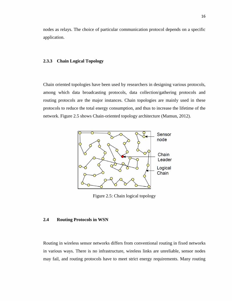
2.3.3 Chain Logical Topology
Chain oriented topologies have been used by researchers in designing various protocols,
among which data broadcasting protocols, data collection/gathering protocols and
routing protocols are the major instances. Chain topologies are mainly used in these
protocols to reduce the total energy consumption, and thus to increase the lifetime of the
network. Figure 2.5 shows Chain-oriented topology architecture (Mamun, 2012).
Figure 2.5: Chain logical topology
2.4 Routing Protocols in WSN
Routing in wireless sensor networks differs from conventional routing in fixed networks
in various ways. There is no infrastructure, wireless links are unreliable, sensor nodes
may fail, and routing protocols have to meet strict energy requirements. Many routing

17
algorithms were developed for wireless networks in general. There are many types of
routing protocols in WSN, which are classified as follows:
Table 2.1: Routing Protocols for WSNs
Category Representative Protocols
Location-based Protocols MECN, SMECN, GAF, GEAR, Span, TBF, BVGF,
GeRaF
Data-centric Protocols SPIN, Directed Diffusion, Rumor Routing,
COUGAR, ACQUIRED, EAD, Information-Directed
Routing, Gradient-Based Routing, Energy-aware
Routing, Information-Directed Routing, Quorum-
Based Information Dissemination, Home Agent
Based Information Dissemination
Hierarchical Protocols LEACH, PEGASIS, HEED, TEEN, APTEEN
Mobility-based Protocols SEAD, TTDD, Joint Mobility and Routing, Data
MULES, Dynamic Proxy Tree-Base Data
Dissemination
Multipath-based Protocols Sensor-Disjoint Multipath, Braided Multipath, N-to-1
Multipath Discovery
Heterogeneity-based Protocols IDSQ, CADR, CHR
QoS-based protocol SAR, SPEED, Energy-aware routing

18
2.4.1 LEACH protocol
LEACH: Low-Energy Adaptive Clustering Hierarchy (LEACH) (Ben & Mohsen, 2011)
is one of the most popular hierarchical routing algorithms for sensor networks. The idea
is to form clusters of the sensor nodes based on the received signal strength and use local
cluster heads as routers to the sink.
Figure 2.6: LEACH Protocol
This will save energy since the transmissions will only be done by such cluster
heads rather than all sensor nodes. Optimal number of cluster heads is estimated to be
5% of the total number of nodes.
All the data processing such as data fusion and aggregation are local to the
cluster. Cluster heads change randomly over time in order to balance the energy
dissipation of nodes. This decision is made by the node choosing a random number
between 0 and 1 (Thakkar and Kotecha, 2014). The node becomes a cluster head for the
current round if the number is less than the following threshold:
𝑇 𝑛 =
𝑝
1−𝑝∗(𝑟 𝑚𝑜𝑑 1
𝑝
0
)
where p is the desired percentage of cluster heads, r is = the current round, and G is the
set of nodes that have not been cluster heads in the last 1/p rounds.
LEACH achieves over a factor of 7 reduction in energy dissipation compared to
direct communication and a factor of 4-8 compared to the minimum transmission energy
𝑖𝑓 𝑛 ∈ 𝐺
Otherwise
(2.1)

19
routing protocol. The nodes die randomly and dynamic clustering increases lifetime of
the system.
LEACH is completely distributed and requires no global knowledge of network.
However, LEACH uses single-hop routing where each node can transmit directly to the
cluster-head and the sink. Therefore, it is not applicable to networks deployed in large
regions. Furthermore, the idea of dynamic clustering brings extra overhead, e.g. head
changes, advertisements etc., which may diminish the gain in energy consumption.
2.4.1.1 LEACH Architecture
LEACH is completely distributed, requiring no control information from the base
station, and nodes do not require knowledge of the global network. It runs with many
rounds. Each round begins with a set-up phase when the clusters are organized, followed
by a steady-state phase when data are transferred from the nodes to the cluster head and
on to the BS, as shown in Figure 2.7.
Figure 2.7: Time line showing operation of LEACH
The steady-state phase duration is usually much longer than set-up phase duration.
However, the first phase is more important, in which sensor nodes are allowed to elect
themselves as cluster-heads randomly, and then divided into clusters. Each node that
becomes the cluster head (CH) will create a TDMA schedule for the sensor nodes within
the cluster. That allows the radio components of each non-CH node to be turned off all
times except during their transmit time ((Heinzelman, Chandrakasan and Balakrishnan,
2000).

20
2.4.1.2 Cluster Head (CH) Selection
LEACH forms clusters using a distributed algorithm in which nodes make autonomous
decisions without any centralized controlling (Heinzelman, Chandrakasan and
Balakrishnan, 2000)
In the beginning of round r + 1 (which start at time t) with probability 𝑃𝑖 𝑡 , each
sensor n elects itself to be CH. 𝑃𝑖 𝑡 is chosen such that the expected number of
CH nodes for this round 𝑘. Thus, if there are N nodes in the network
𝐸 #𝐶𝐻 = 𝑃𝑖 𝑡 ∗ 1 = 𝑘𝑁𝑖=1 (2.2)
where :
N is the number of sensor nodes,
𝑃𝑖 𝑡 is the probability with which node i elects it to be (CH)
𝑘 is the expected number of cluster-head
Each node will be cluster head once in 𝑁
𝑘 rounds
Probability for each node i to be a cluster head at time t, 𝐶𝑖 𝑡 = 𝑖𝑡 determines
whether node i has been a cluster head in most recent (r mod (𝑁
𝑘)rounds). (i.e:
𝐶𝑖 𝑡 = 0 if node i has been a CH and one otherwise), then each node should
choose to become CH at round r with probability.
𝑃𝑖 𝑡 =
𝑘
𝑁−𝑘∗ 𝑟 𝑚𝑜𝑑 𝑁
𝑘
0
(2.3)
Nodes that have not previously been a CH and considered to have more energy
available from the node that recently have intensive energy function can be a CH
at round r + 1.
𝐶𝑖 𝑡 = 0
𝐶𝑖 𝑡 = 1

21
The expected number of nodes that have not been a CH in the first round r is N –
k x r
After 𝑁
𝑘 rounds, all nodes expected to have been CH once, following which they
are eligible to perform this task in the next sequence of rounds.
Since 𝐶𝑖 𝑡 is one if node i is eligible to be CH at time t and zero otherwise, the
term 𝐶𝑖 𝑡 𝑁𝑖=1 represent the total number of nodes that are eligible to be a CH at
time t ,
𝐸 𝐶𝑖 𝑡 𝑁𝑖=1 = 𝑁 − 𝑘 ∗ 𝑟 𝑚𝑜𝑑
𝑁
𝑘 (2.4)
This ensures energy at each node to be approximately equal after every 𝑁
𝑘
rounds. Using equation (2.3) and (2.4)
𝐸 #𝐶𝐻 = 𝑃𝑖 𝑡 ∗ 1
𝑁
𝑖=1
= 𝑁 − 𝑘 ∗ 𝑟 𝑚𝑜𝑑 𝑁
𝑘 ∗
𝑘
𝑁 − 𝑘 ∗ 𝑟 𝑚𝑜𝑑 𝑁𝑘
= 𝑘
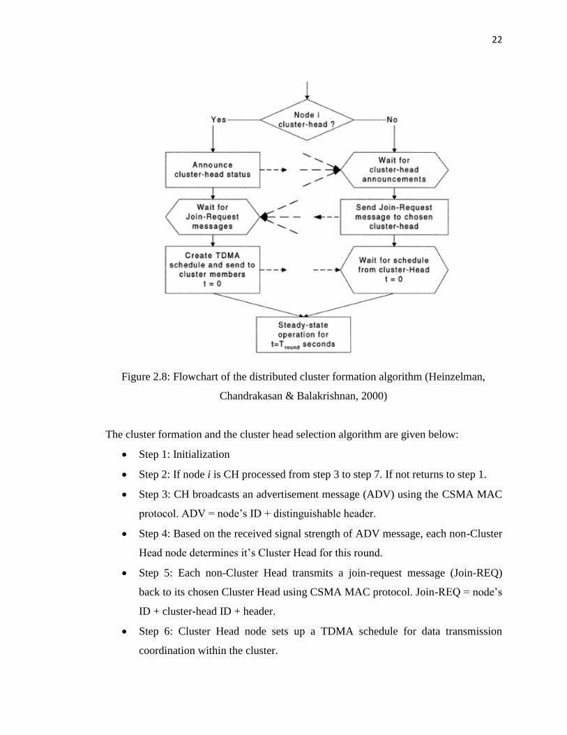
2.4.1.3 Cluster set-up phase
After each node has decided to which cluster it belongs, it must inform the cluster head
node that it will be a member of its cluster. Each node transmits this information back to
the cluster head again using CSMA MAC protocol. During this phase, all cluster head
nodes must keep their receivers on. A flowchart of this set-up phase is shown in Figure
2.8.
(2.5)
22
Figure 2.8: Flowchart of the distributed cluster formation algorithm (Heinzelman,
Chandrakasan & Balakrishnan, 2000)
The cluster formation and the cluster head selection algorithm are given below:
Step 1: Initialization
Step 2: If node i is CH processed from step 3 to step 7. If not returns to step 1.
Step 3: CH broadcasts an advertisement message (ADV) using the CSMA MAC
protocol. ADV = node’s ID + distinguishable header.
Step 4: Based on the received signal strength of ADV message, each non-Cluster
Head node determines it’s Cluster Head for this round.
Step 5: Each non-Cluster Head transmits a join-request message (Join-REQ)
back to its chosen Cluster Head using CSMA MAC protocol. Join-REQ = node’s
ID + cluster-head ID + header.
Step 6: Cluster Head node sets up a TDMA schedule for data transmission
coordination within the cluster.
23
Step 7: TDMA schedule (1. Prevents collision among data messages. 2. Energy
conservation in non-cluster head nodes)
Step 8 : end
2.4.1.4 Steady state operation
By referring Figure 2.7, TDMA schedule is used to send data from node to cluster head.
Cluster head aggregates the data received from nodes in the cluster. Communication is
via direct-sequence spread spectrum (DSSS) and each cluster uses a unique spreading
code to reduce inter-cluster interference. Data is sent from the cluster head nodes to the
BS using a fixed spreading code and CSMA. After a certain time, which is determined a
priori, the next round begins with each node determining if it will become a cluster head
for this round and advertising the decision to the rest of nodes as described in the
advertisement phase. This is the steady-state operation of LEACH networks. The
flowchart of steady-state process is shown in Figure 2.9

24
Figure 2.9: Flowchart of the steady-state operation for LEACH
2.4.2 PEGASIS Protocol
PEGASIS & Hierarchical-PEGASIS: Power-Efficient Gathering in Sensor Information
Systems (PEGASIS) (Lindsey and Raghavendra, 2002) is an improvement of the
LEACH protocol. Rather than forming multiple clusters, PEGASIS forms chains from
sensor nodes so that each node transmits and receives from a neighbor and only one
node is selected from that chain to transmit to the base station (sink). Gathered data