university of technology building and construction
TRANSCRIPT

1
University of Technology
Building and Construction Engineering Department
Building Materials and Projects Management Engineering Branch
R.C.Structure Defects and Rehabilitation
Prof. Dr. Shakir A. Salih
Lec.No.1
Introduction:
The buildings and other different reinforced concrete structures often suffer
of some defects and deterioration which affect the structure by many ways.
There are various causes of these defects and deterioration relate to all
construction steps; the design, materials, shop drawings, work conditions,
quality control and others.
It is aimed from this vital subject to teach the 4th class student the defects
and deteriorations which may be happened to the reinforced concrete
buildings and structures and why they happened in the structures which are
in service. As well as, the measures which must be taken to prevent or
decrease them in the new structures (during the construction period or in the
structures which are to be built in the future), then study the best way to
repair them.
To achieve that, the subject will be studied from all its sides. The
construction activities and stages will be displayed and discussed. The
design criteria, structural materials, specifications, site conditions, workers’
skills and execution technology and its effect on the commonly happened
defects are to be discussed too. The traditional construction stages such as
foundations, columns, beams and slabs are to be discussed thoroughly and
the best practical ways to avoid these defects and deterioration during
construction period or in the future.
It is worthy to point out that this subject is not existed in a specific text book.
It depends on many references and subjects the student has had in the

2
previous years. The references of materials technology, concrete technology,
structural theory, soil mechanics, reinforced concrete design, project
management, quality control and others can be useful.
Below is a brief of the most important topics and references in the syllabus:
This subject is for the 4th class students. 2–hour lecture is to be delivered
weekly, which means 60 hours over the academic year. It is hopeful to
discuss and study the following topics:
1. The design criteria and their effect onbuilding defects and deterioration
and their maintenance.
2. Evaluation of defected reinforced concrete structures.
3. The structural materials used to repair defects and deterioration.
4. The main causes of cracking in concrete structures and their repair
methods.
5. The foundations’ defects and causes and their repair methods.
6. The reinforced concrete columns’ defects and causes and their repair
methods.
7. The reinforced concrete beams’ defects and causes and their repair
methods.
8. The reinforced concrete slabs’ defects and causes and their repair
methods.
9. The roofing work defects and cause in buildings and their repair
methods.
I’d like to turn the student attention that what is existed in internet is just an
abbreviation of the subject and very brief, so, the student has to attend the
lectures to have all the information about the subject and to discuss it.
At last, it is possible to make use of the following references for more
information about any subject discussed in the lecture.

3
1. Derek Osbourn and Roger greeno, “Introduction to building”, Pearson
Prentice Hall, 3rd
Ed. 2002.
2. Philip H. Perkins, “Repair, Protection and Water Proofing of Concrete
Structures”, E.A.S.P., London and Newyork 1986.
3. Neville A.M, and Brooks J.J.” Concrete Technology”, John Wiley and
Sons, Newyork, 2005.
المصدر السابق باللغة العربية ترجمة ا�ستاذ الدكتور شاكراحمد صالح وا�ستاذ الدكتور محمد .4
. ايوب العزي
الجامعة , وزارة التعليم العالي" تكنولوجيا الخرسانة" د ھناء عبد , مؤيد ويوسف. د, الخلف. 5
.1991, التكنولوجية
6. The lecturer theoretical and practical experience in design and in site
works.

4
Lec.No.2
Design Criteria and their Effect on Building
Defects and Maintenance
When there is a need to construct a project, all the involved sides start
working and coordination to fulfill the task in the best possible way. This is
to insure the following:
o G
ood looking.
o S
trength.
o D
urability.
o E
fficiency in use.
o M
aintenance needs.
o L
east cost.
They aim to put measures to be applied in design and execution processes so
as to take the following in consideration:
o E
xpected defects and deteriorations.
o C
onstruction monitoring and periodical maintenance.
The above mentioned points affect the cost, likewise during construction
period and during the use of construction.
Aiming to use the construction for the longest possible time with least
periodical maintenance cost, three weeks will be devoted to discuss the
following:
o I
mportance of design criteria.

5
o D
esign criteria effect on defects and maintenance.
o D
esign criteria effect on construction efficiency and its useful life.
The periodical maintenance and monitoring system effect on the cost:
With regard to building construction and use, the common mistake now is
that there is no monitoring system for the building during use. Besides, no
thinking in maintenance needs during design or execution processes. This
affects the cost remarkably.
It’s wrong to postponed defects maintenance after they take place. The
problem will escalate. And this leads to increase maintenance cost. In other
words, building cost increases with time. The following Fig. represents the
relationship between cost and time with and without periodical monitoring
system.
Cost maintenance cost without monitoring
Maintenance and
monitoring
cost
Monitoring system cost
Time (Year)

6
2nd
lecture/ (3)
Defects Reasons in Buildings:
There are many reasons cause some defects in buildings, among which are:
1. Design.
2. Specifications
3. Materials.
4. Site & Construction.
5. Use.
From what above mentioned there are many probabilities may lead to
defects in any specific structure, and to limit or at least to reduce those
defects to prolong the structure life and to reduce its periodical maintenance
cost, maintenance issue must be taken in consideration in all stages of the
structure starting from choosing the site and the design until the way of
using the building in the right way. This will be discussed in details later.
Designs criteria and their effect on defects:
The essential goal in all structures from the beginning and when the idea
comes out even before making the needed designs is to construct an
integrating building in which is as less defects as possible and is to be
employed for the longest possible time and by the least possible maintenance
cost.
To achieve this goal, a cooperation and coordination between many sides
must be done in each of the project stages in a way that assures the
fulfillment all the necessities to complete the task successfully.
Design stage is one the stages which should be taken in consideration to
avoid the defects that take place due to design reasons and the design teams
have to think about the maintenance and future defects treatment and put
them in the design philosophy and never neglect this matter, while

7
concentrate on good appearance only. The durability, use efficiency and
total cost are important and must be taken in consideration for all buildings.
The good design must include the following criteria:
First: the parties who have essential role in design stage:
1. The owner………..
2. The designers…….
3. The executers……..
4. The monitoring and maintenance team…..
Second: the design at least must cover the following:
1. A good looking and suitable building……..
2. Suitable materials according to the specifications are to be used……
3. The construction must be guaranteed by quality control in accordance
with needed specifications.
4. The design must not ignore any of the necessary services and utilities…..
5. The assurance of that the building is to be used for the purpose for which
it is constructed.
Third: Cost & Useful life:
The building cost and useful life subject is an important matter, and the four
parties (the designer, the executer, the owner and the maintenance team)
have to have their decision towards it. The cost and useful life affect the
following:
1. The materials which will be used and how much will they match the
specifications.
2. Choosing the suitable finishing materials……

8
3. Providing other essential services in the building such as foundation
protection, sewage and water supply works, electrical work, air conditioning
and etc.
4. Choosing the suitable fittings and accessories …….
Fourth: the designer experience in building maintenance that the lack in
experience in this subject leads to ignore some important things in this issue.
Fifth: the designer responsibility:
The common concept nowadays is that the designer responsibility ends with
delivering the designs and drawings; this is wrong concept…….that the
designer must stay responsible as long as the building is in use and a defect
due to the design takes place.
Sixth: Making use of materials in the right way according to producer
instructions and material’s special specifications that ignoring this matter
will affect the durability adversely….i.e. (the material which is to be used
indoor must not be used outdoor).
Lec.No.3
Seventh: The bad design may lead to many defects in the structure which
affect the total structure cost due to renovation cost.
Eighth: the designer has to take in his consideration the defects which may
probably take place as well as he has to think about the maintenance needs
during designing process, not to ignore this matter until it happens.
Ninth: when design any of the building parts; the good designer has to have
answers to the following questions:
1. How to reach that part?

9
2. How to clean it?
3. How long is its useful life?
4. How to substitute it?
Tenth: the designer has to have enough detailed information about the
durability effective factors in order to take them in his consideration during
choosing between materials and protections alternatives. Example of these
factors:
1. Water table.
2. The moisture.
3. Chlorides and other chemicals.
4. The temperature fluctuation.
5. Steel reinforcement corrosion.
6. Insects, bacteria and other organic materials and their effect on different
building materials.
7. Other atmospheric conditions .
8. The expected natural disaster.
9. All environmental pollution types.
Eleventh: the designer has to know all the new materials and he has to be
sure of these materials compatibility and suitability to be used in the proper
place. This affects the building durability and how much this building will
need a future maintenance.
Twelfth: Some changes may take place after or during construction period,
the designers must know that. For example the offshore buildings expose to
water currents and tide and high buildings expose to air currents or what
belongs to environment pollution in the industrial structures and others.

10
Thirteenth: thermal and acoustic insulation must not be ignored and
measures must be taken for heating, cooling and ventilation and other
essential services.
Fourteenth: Site must be investigated thoroughly; trees, obstacles and old
embedded services systems….etc.
Fifteenth: the designer must know the structure site surrounding buildings
and their foundations and the site nearby available services.
……………………………………………………….
The Effect of Dimensions Standardization on Defects Treatment:
Generally each of structural materials especially finishing materials and
fittings has its life cycle according to its type and the way it is used. For this
reason the companies produce standard dimension materials.
A good design must deal by high accuracy with this matter that it has a
significant effect on the maintenance in the future. The designer must take
the materials standard dimensions in his consideration during design
process, this will participate in simplifying the materials getting process in
future to substitute them in maintenance work and defects’ treatment.
The interest in standardize the dimensions and the use of the available
materials will undoubtedly; effect the inhabitation cost in the building and
on maintenance simplicity and cost.
There are many examples of the standard dimension, such as:
Doors…..(all types).
Windows.
Bricks.

11
Tiles.
Ceramic tiles.
Marble…
Stairs.
False ceiling
Pipes (all different pipes).
Electrical fittings.
Sanitary fittings.
Mechanical fittings.
Plates.
reservoirs
furniture.
Plates and decoration.
Later, examples will be discussed.
………………………………………………………………………….
The construction materials used for defects treatment Lec.No.4
The structural materials highly affect the structure’s strength and durability
and life cycle. There is a high percentage of defects due to structural
materials. On this base, the engineer must have a good knowledge about
common structural materials used in construction as well as the new
materials in order to be able to choose the proper materials in both
construction and repair and avoid future defects as well.
Structural materials are given to the student by many courses. In this course
the focus will be on the measures which are to be followed by the engineer
to use suitable materials for a specific construction.

12
Concrete
Huge quantity of concrete is used in construction sector in Iraq for the
advantages it has and the availability of its raw materials. Concrete is a mix
of cement, aggregate and water and sometimes with admixtures. Good
materials (according to specifications) must be used to insure high quality
concrete with regard to strength and durability, as well as high efforts must
be given to all concrete producing process such as handling, compaction,
finishing and curing….etc.
The following is a brief to what must be known about different concrete
work materials and processes.
A. Cement: cement plays large role in concrete properties. The reliable
specifications must be known, among which, Iraqi specifications No. 5,
1894. The most important things which must be known about cement are:
Type.
Initial and Final Setting Time.
Fineness.
Main compound.
Miner compounds, such as phosphates, alkalis and magnesia…
Soundness.
Insoluble residue.
Loss on ignition.
Compressive strength.
The specifications mention the allowable limits for each of the above
properties to insure using high quality cement. For many reasons, in
maintenance and defects treatment, the same old concrete cement type is
used.
B. fine and coarse aggregate:

13
Aggregate represents 75% of concrete, so it has significant role on concrete
properties, for this, the engineer must know the sampling and check the
aggregate according to Iraqi specifications No.45, 1984. The things must be
known are:
Source and mineral composition…
Type….
Grading and fine materials percent.
Maximum aggregate size.
Sulfate content.
Absorption.
Bulk density and specific gravity.
Organic and other materials percent.
C. water: it is used to produce fresh concrete and to cure hardened concrete.
Water must not contain mud or salts or acids or any other chemicals. There
are tests to check water but generally, there are no dangerous problems with
regard to water in Iraq.
D. Admixtures: there are many admixtures used to add a specific desired
properties while concrete is fresh or hardened. The common admixtures are:
Accelerators.
Retarders.
Plasticizers.
Superplasticizers.
Air entrained admixtures.
Water expelled admixtures.
Color admixture.

14
Fine mineral admixtures, such as pozzolana and silica.
British and American specifications (B.S 5075, ASTM C494) can be reliable
to check out the admixture quality. Generally, an engineer has to know :
Admixture type, how does it work, the quantity to be used, how to use it, the
side effects, suitability, cost and the future treatment….etc. it is preferable to
make tests mixes to be sure of the concrete properties with admixtures.
E. Mix proportion: It affects highly the produced concrete properties. Mix
proportion is decided to produce a concrete (fresh and hardened) with
specific properties by using the available materials. British or American
method is often used to design the concrete mixtures, during design the
following things must be known:
The lower and upper water content limit.
The upper w/C ratio limit.
The required compressive strength.
The required workability (slump).
The used aggregate properties.
Cement type.
The admixture type (if existed).
Trial mixes are often required.
F. Concrete handling and compaction: there are many ways to convey, cast
and compact the concrete. And in order to avoid any defect, the following
things must be assured:
Homogeneous mixture.
Concrete must be cast in its place within the first hour .
Segregation must be avoided.
Bleeding must be avoided.

15
Good compaction in order to have the highest possible density with
minimum porosity and permeability.
Good finishing and leveling.
Concrete must be workable enough to fill the form.
G. curing of concrete: there are many methods of curing, among which
traditional and new methods. The curing purpose is to keep the concrete
moist and prevent mixing water from evaporation to provide suitable
conditions for cement hydration (reaction between cement and water) and
strength gaining. Good curing participates in preventing plastic shrinkage
cracks which affect the concrete strength and durability.
Among the common curing methods is continuous water spreading starting
from solidification till seven days or put water on the concrete surface as it is
done for slabs or steam curing in the precast industries, or making elastic
membrane by using chemicals to prevent water evaporation from concrete.
………………………………………………………………………………

16
Steel ReinforcementLec.No.5
It is used in reinforced concrete structural parts to enhance the concrete to
resist tensile stresses. On this base, an engineer has to know steel properties
and the required measures to protect it against corrosion and other damages.
The followings should be known:
o Steel properties especially, Ultimate strength and Yield strength
(Grade 40,50 or 60).
o Steel types:
Reinforcing Bar.
Wire.
Prestress Bar.
Prestress wire.
PresstressSrand.
It is important to know the stress strain relationship and the measures
to protect the steel against corrosion (concrete cover and painting).
The molds:
Molds have significant role during construction. The molds are used
to support the concrete safely without deformation or seepage till the
concrete solidifies and gains the required strength.

17
The following should be checked in mold work:
Mold design.
Proper side and vertical supports.
Leveling.
The thickness for concrete cover.
Molds parts must be well connected to each other.
Make the openings according to drawings.
Mold removal timing.
Walls building materials:
Walls building materials are so important especially, clay bricks. In
order to avoid the probable defects, materials quality must be checked
as well as building process. Accordingly, concentration must be on the
following:
o The use purpose (partition or bearing wall).
o Dimensions and appearance.
o Strength.
o Absorption, toughness, fluorescence, salt content.
o Density of light weight blocks.
o Voids and openings.
Checking bonding type, wall thickness, mortar thickness, mortar strength,
joints, straightness, perpendicularity, wall curing …..
Tiles, marbles and roofing concrete tiles:
Floor and roofing finishing works are so important and they represent
high cost percent, important work precedes tiling. However, the measures
in materials choosing:
Appearance, planeness, cracks and homogeneity.
Total thickness, mosaic thickness and color.

18
Type and reliable specifications.
Strength.
Absorption.
Salts.
Checking succeeding work.
Doors and Windows:
this is also important work. The cost varies from low to high that there
are a lot of types in markets. Good work needs to know the following:
Type.
Section, frame and specifications.
Dimensions.
Bolts, hinges, handles ….etc.
Glass.
Painting.
Installation.
Service systems:
sanitary systems, sewerage system, water supply system ….execute
according to drawings…(sewers, pipes, manholes, how to make
inspection and substitution).
Water system…everything belongs to connection, storage and supply.
Electrical system…. everything belongs to electrical fittings and services.
Mechanical and air conditioning system….

19
Other building works
Building materials subject is so wide range one. And the above
mentioned is just a brief. All building materials must be taken in
consideration as plastering, false ceilings, painting….etc. each of them
has its specification and life cycle.
……………………………………………………………………………
Foundation Defects and Solution. Lec.No.6
Foundations have great importance in constructions, that if defects appear
in foundation, the results will be reflected on the whole construction. For
this, special attention must be given to ensure high quality and durable
foundations.
Site condition:
Site condition must be studied thoroughly before foundation design.
What must be studied are:
Are there signs of defects in the neighbor buildings?
Are there special foundation type used in nearby buildings?
Are there signs of soil sliding….soil sliding may take place in sites with
inclination more than 1: 1.5? The case may appear as wide parallel cracks
and obvious soil failure.
Are there signs of that the soil is fill or transported from other sites or the
site contains debris….etc?
Is the site soil stable during summer and winter?
Are there large and high trees in the site?
Are there signs that float from the nearby rivers come over the site or
earthquake …etc?
20
What was the site used for?
Is there probability pollution in the site?
Is the site in oil well area or coal mine area……..etc.
Is there an old construction in the site? Will the demolition affects the
nearby construction(s)?
Are there signs of old service system(s) embedded in the site?
Soil Investigation
The defects belong to soil maybe due to poor or insufficient study to the
site nature and the surrounding conditions. These defects maybe due to
improper foundation type with regard to transmitted forces or soil
properties or foundation level.
After studying the site as mentioned earlier , the specialists are asked to
make soil investigation report, accordingly, the following will be known:
1. Bearing Capacity: the soil failure under foundation due to stresses
more than what the soil can resist.
2. Water table level that the variation and fluctuation of water table level
due to nearby rivers or irrigation or seepage from services systems, the
nearby trees also may cause defects in structures.
3. Soil nature with depth, is it sandy? Clayey? Or mix of them? Or
rocky…..?
4. The particles size, this affects the water expelling rate which leads to
settlement, then the soil strata will be compressed under building weight.
For this, total or differential settlement by more than the allowable limit
takes place.
5. In report, there are recommendations about the suitable foundation for
the site soil and structure loads.

21
6. The expected settlement is also included in the report.
All the above mentioned information enable the designer to choose the
suitable foundation and the report will be a guide for the executive
engineer to avoid soil obstacles (if there is any) during execution.
Common Foundation Problems or Defects
The defects in structure may result from one reason or more. Among
these reasons are the soil and the foundation. And among these defects
which take place in all foundations’ types:
1. The foundation differential movement due to loads. This often happens
in shallow foundations such as strip foundation, isolated foundation, and
combined foundation.
The loads compress the soil and according to this compression and soil
properties settlement will take place proportionally with time, this
settlement may keep on for 20 years, but the 1st five years often be the
crucial period in determining the maximum settlement occurs due to
loads.
The difference of loads on columns or bearing walls leads to differential
settlement and this leads in all cases to additional stresses on the structure
which lead to serious problems. These problems need to be treated.
Movements Resulting from other Causes
This movement may happen due to seasonal climate fluctuation which
the soil displays to, or trees demolition or new trees planting. This
problem depends directly on soil type, especially on particles sizes and
their fineness degree which can be classified as:
A. Clay soils: as long as clay soil shrinks by drying and swells by
moistening, this affects the shallow foundations.

22
The shrinkage in clayey soil is measured in summer with trees existence
which absorbs the water from about 5 meters depth…..the shrinkage
reaches 100 mm (very high shrinkage whichnegatively affects the
structure).
The highest effect will be on foundation corners and edges.
The foundation must be far from the huge trees by a distance at least
equal to the tree height if there is one tree but the distance must be equal
1.5 times the tree height if there is a group of trees.
When removing trees from clayey soil, sometime is to be given to the soil
to let it takes its final shape then work can be started.
Generally, shrinkage of clayey soil under foundation may cause
foundation deviation as a result of differential settlement or fractured
foundation due to heterogeneous support under foundation.
……………………………………………………………………………
Lec.No.7
B. Sandy soil: the dense sandy soil is very good base for foundation but
the water table which takes the fine particles will make it unstable soil.
Besides, freezing water in soil pores leads to increase volume, this may
takes place from surface to 600mm depth and causes lifting pressure
which affects soil surface, foundation, floors and corridors….etc. this
phenomenon called Frost Heave.
C. Organic Soil: the soil which contains organic materials such as
decayed plants roots and other organic materials. This soil type
distinguished by volume changes due to moisture content as well as it is a
compressible soil. These characteristics negatively reflect on foundation
stability and its durability.

23
The building of constructions on such soil is very dangerous and
generally, affects the construction stability. Moreover, any repair does
not mean getting rid of the problem that the damages may take place
again because the differential movement for such construction cannot be
calculated or estimated.
D. Fill or Make up Ground:
The fill soilhighly affects the foundation as it is mentioned in paragraph
(C), unless the soil is well chosen and compacted in layers.
There are a lot of low lands filled up with debris and industrial residue or
used up materials such as vehicles tires, metals, different types of
containers or trash and so on, this leads to differential foundation
settlement or cause damage to foundation.
Design of Foundations
Foundation design depends on many factors. And there are many
foundations types, the foundation type is chosen according to loads and
soil characteristics. Anyway, each foundation has dimensions and depth
under natural ground level.
Foundation depth depends on;
1. How to reach a suitable bearing capacity.
2. The depth is to be suitable especially in clayey soil to avoid volumetric
changes due to drying and wetting.
3. With regard to sandy soil, the depth must be far enough so as not to be
affected by freezing to get rid of uplifting forces caused by freezing.
The failure may be resulted from unsuitable dimensions or reinforcement
or depth.
Concrete in Foundations
Foundation concrete is affected by many factors, among which:

24
1. Cement type. 2. Aggregate type and characteristics. 3. Water content
and mix proportion. 4. Mixing, handling, finishing, compacting and
curing.
The produced concrete strength must be higher than the design strength.
Cement content must not be less than 300kg/m3 and the strength at 28
days must not be less than 25MPa and w/c must be between 0.4 and 0.6.
Concrete type may cause early failure in foundation as well as the
unsuitable dimensions especially the thickness may cause foundation
failure.
Foundation Execution
There are many foundation defects caused by execution reasons in situ.
Accordingly, execution must be with high accuracy in order to reduce
these defects, this is done by the following measures;
1. Site leveling and cleaning till reaching the natural ground level.
2. Foundation layout on the ground according to drawings.
3. Excavation:
o Accurate dimensions (length, width and thickness).
o Ensure no damage is to be happened to the neighbor buildings.
o Ensure the excavation straightness and perpendicularity.
o The excavated soil must be away from the excavation not to fall
down during work.
o Ensure the excavation level and plainness.
o Side support is to be used if there is a need for it.
o Ensure accurate water table pumping.
4. Excavation bed must be well compacted and sub base layer must be
used.

25
5. Broken bricks layer is used and or concrete layer of 10 cm with
applying a water proofing cover.
6. Fixing steel reinforcement:
o According to drawings.
o Steel must be clean( no corrosion, mud or oil) so as to ensure good
bonding.
o Ensure the concrete cover (this is very important).
7. Casting:
a. ensure homogeneous mixture and avoid extra water(to simplify the
work) or reducing cement quantity (to reduce the cost).
b. Concrete segregation must be avoided and no mud is to be with
concrete.
c. Concrete must be well compacted so as to expel the air and reduce
voids as much as possible. Concrete must flow and surround steel
reinforcement; special care must be given to the dense reinforcement
places.
d. Measures must be taken in rain, hot or cold weather in order to ensure
suitable circumstances during concrete casting process.
8. Ensure sufficient curing by water or other means.
9. Ready mix is to be used to have large quantity in short time.
The foundation concrete failure takes place as a result of either the
concrete is weak, heterogeneous mixture or unsuitable concrete materials.
Settlement of Buildings
The buildings settle for many reasons:
o Inadequate or improper chosen foundation (foundation type,
dimensions, reinforcement, concrete, execution…..etc.).
o Low bearing capacity.

26
o Soil shrinkage (in case of clayey soil drying).
o Huge trees nearby the buildings cause settlement at the end of
summer season.
o Huge excavation nearby the buildings leads to settlement later.
o Settlement can be known from crack; especially those nearby the
openings in the walls such as doors, windows and arches. It can be
noticeable that the use of doors and windows is somehow hard,
especially at the end of summer and the start of winter.
………………………………………………………………………
The treatment or repair of settled foundationsLec.No.8
Foundation treatment andrepair is a difficult, complex and costly process
in most cases and each case needs special treatment according to its
conditions.
The defect in foundation must be repaired quickly so as to avoid
damages accumulation.
There are many defects in foundations result of different reasons. Here,
twomethods will be discussed which enhance:
o Strengthen the foundation for additional loads or to improve it.
o Settlement stoppage.
o Stoppage of wall cracks resulted from differential settlement.
First:
Underpinning of Foundation and Settlement
The damages in buildings walls resulted from differential settlement
need radical reclamation by construct new foundation under the old
foundation to support it. This is done by consecutive steps but with care
not to cause any damage or failure to the building. Mostly, the
reclamation is to the outer foundation according to the following steps:
1. Cleaning the area under repair.
2. Removing the live load as much as possible to reduce the load over
the foundation under repair.

27
3. The walls and slabs over the foundation are to be supported by:
o Vertical shores (for slabs).
o Raking shores (for walls).
o Flying shores (for walls).
4. After that, openings of suitable depth and width are to be excavated
under and beside the foundation so as to simplify the casting of the
new foundation. With regard to this point, the following must be
taken in consideration:
a. The excavation under the foundation must be in parts, each part
length must be within (1m to 1.5m) so as to ensure the old
foundation safety or the distance must not exceed( 1/4) times the
length of the normal loaded bearing walls or (1/2) times the length of
heavy loaded bearing walls.
b. The openings are to be excavated consecutively in a manner shown
below so as each opening is being far from the other one:
c. The excavation of any part is never to be started unless the previous
part is completely supported and as well as the old and new foundations
are supported.
d. The excavation depth or width reaches the damaged soil and it often
exceeds 90cm.
e. the excavation sides are to be vertical and well supported as well as
the bottom must be leveled.

28
5. The supporting foundation must be casted according to designed
dimensions as well as the steel reinforcement:
a. Ensure the needed foundation thickness and the reinforcement must
be bent so as to ensure good bond with the other following parts.
6. Ensure good bond in brick work and in foundation reinforcement
between all parts so as at last all parts will act as one part.
_
7. The process goes ahead till the end. Then, the temporary support is to
be removed and wall exterior damages caused by foundation
deterioration are to be treated. After that, the building is to be used in
normal manner.
Second: Simple treatment to limit the deterioration:
The supporting method may be too expensive in specific cases (much
damages and the depths are 5m or more, this may take place due to
huge trees). In such cases, the building is to be surrounded byframe of

29
pre-cast concrete slab (apron) with width of 1.5m, and then the building
is to be left for a whole winter season. Then the cracks are to be
repaired. This method ensure a protection to stop the fast deterioration
in the building by suitable cost. The growing trees are to be removed,
and then the repair is after one season.
It is worthy to be mentioned that there are complex cases out of this
lesson scope.
……………………………………………………………..
Cracks in Concrete Structures: Methods of Repair.Lec.No.9
Introduction:
Cracks are so important to be studied for they cause damages to
buildings and concrete structures. They are defects commonly appear in
both reinforced and plain concrete structures especially in our country
that most of our constructions are concrete structures.
For this, cracks reasons and the methods to repair them are to be studied
to maintain buildings safety and insure long life and durability. Cracks
may be different according to their types, shapes, their causes and how
to find the suitable way to repair each of them, in addition to suggest
the suitable materials to repair those cracks.
Cracks types:
Generally, there are two cracks types and there are many
reasons cause each of them. They are:
1. Structural cracks.
2. Nonstructural cracks.
1.Structural cracks:

30
The cracks which take place in reinforced structural members, such as
foundations, columns or beams …etc. they often dangerous and need
rapid treatment.
2. Nonstructural cracks:
The cracks which take place for other reasons not those of structural
cracks. They often not dangerous in the beginning and do not harm the
structure but when ignore them, they are changed into dangerous cracks
and their effect may accumulate to be dangerous structural cracks.
Cracks classification according to their nature:
Generally, cracks can be classified to:
a. Moving cracks: the cracks which their lengths, widths and/or depths
are increased. They are the most dangerous and high experience and
studies are needed to repair them.
b. The constant cracks: the cracks which if the cause is removed, they
stay constant in lengths and widths. They are less dangerous than the 1st
type and can be repaired easily.
c. Fresh concrete cracks: they often take place during casting process
that hair cracks appear on concrete surface after some minutes of
concrete finishing process.
d. Hardened concrete cracks: These cracks take place in hardened
concrete due to drying shrinkage, chemical factors, oxidation, sulfate
attack, freezing and concrete differential settlement effects.
Cracks diagnosis and monitoring: to know the reason of any crack
and to suggest the best way to repair it, the engineer has to watch and
study the crack as follow:
o Crack place.

31
o Crack direction.
o Crack path.
o Crack length, width and depth.
o The crack is deep or not.
o The crack seasonal extending with time.
o Crack propagation degree.
o The way of crack propagation (arbitrarily or systematically).
o The distance between two cracks.
The causes of nonstructural cracks in concrete:
First: in fresh concrete
There are many reasons cause cracks for concrete (structural or
nonstructural), the most are:
1. Cracks due construction movement, they are of two types
• Cracks take place when the soil goes down under the concrete in
the period between placing and gaining enough strength. This
soil falling dawn is due to either by moisture content changes or
incomplete soil compaction. Theses cracks appear within some
hours or some days after casting process.
• Cracks due to form movement, this movement in the concrete
early age may cause cracks even if it is simple movement which
often happens due to unsuitable form design, form wood
saturation, pins looseness and too much concrete compaction.
These cracks appear within the early hours of casting.
2. Cracks due to settlement shrinkage: they are classified into
two branches

32
• Cracks around steel bars, they occur when the concrete upper
part partially sets while aggregate particles still in
sedimentation, this sedimentation causes water rise between
aggregate particles and then reduction in volume and concrete
falling down in all form area except steel bars places, this
leads to vertical cracks parallel to steel bars. These cracks
may weaken or cause to lose the bond between concrete and
steel bars. These cracks often occur in deep beams and within
the early hours of casting.
Fig (1)shows the sedimentation shrinkage around steel bars.
• Cracks around aggregate occur due to settlement shrinkage and
the mechanism is similar to that of steel bars.
3. Cracks due to setting shrinkage: they are of two types
• Plastic shrinkage cracks, they occur when the evaporation from
concrete surface is faster than bleeding (water rise to concrete
surface. This happens due to high wind velocity, low relative
humidity and high temperature. This leads to shrinkage in
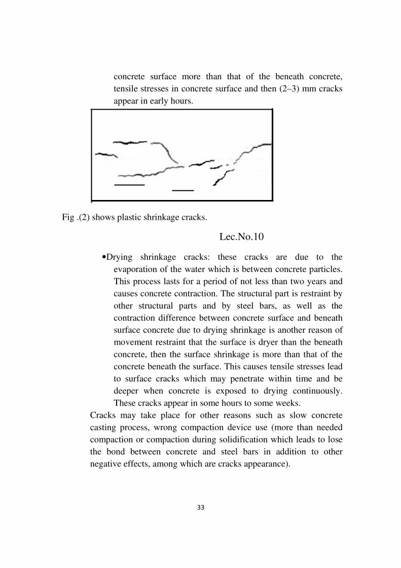
33
concrete surface more than that of the beneath concrete,
tensile stresses in concrete surface and then (2–3) mm cracks
appear in early hours.
Fig .(2) shows plastic shrinkage cracks.
Lec.No.10
• Drying shrinkage cracks: these cracks are due to the
evaporation of the water which is between concrete particles.
This process lasts for a period of not less than two years and
causes concrete contraction. The structural part is restraint by
other structural parts and by steel bars, as well as the
contraction difference between concrete surface and beneath
surface concrete due to drying shrinkage is another reason of
movement restraint that the surface is dryer than the beneath
concrete, then the surface shrinkage is more than that of the
concrete beneath the surface. This causes tensile stresses lead
to surface cracks which may penetrate within time and be
deeper when concrete is exposed to drying continuously.
These cracks appear in some hours to some weeks.
Cracks may take place for other reasons such as slow concrete
casting process, wrong compaction device use (more than needed
compaction or compaction during solidification which leads to lose
the bond between concrete and steel bars in addition to other
negative effects, among which are cracks appearance).

34
The hardened concrete cracks:
There are many reasons for hardened concrete cracks, among which:
1. The late drying shrinkage cracks. The mechanism of these cracks is
similar to that of drying shrinkage but they are deeper and appear after
weeks or months.
2. Cracks due to chemical reasons such as the reaction of cement with
carbon dioxide existed in the air (carbonation) or with aggregate particles or
may be resulted from steel corrosion; accordingly, they can be classified as
follow:
a. Carbonation: cracks result from chemical reaction between cement
compounds and carbon dioxide from the atmosphere. They are so thin
cracks and distributed irregularly on the concrete surface.
b. The aggregate alkali reaction: this type of cracks result from the reaction
between active silica (non–crystalline silica which existed in some
aggregate types) and cement alkalis, the result of this reaction is alkali silica
gel which has the ability of unlimited swelling with the existence of
external moisture, this leads to internal stresses and then cracks and
concrete deterioration. These cracks are similar to carbonation cracks in
appearance.
c. Oxidation cracks (corrosion): they are often caused by volume increment
due to corrosion, corrosion products volume is as much as 2 or 3 time the
original volume. Then, longitudinal cracks appear parallel to steel
reinforcement. This type of cracks appears in a period of some months or
years.
d. Salts attack cracks: the essential salts compounds are sulfates, chlorides
and calcium or potassium or magnesium carbonate. Salts attack concrete
through two ways; 1. External salts attack (soil and water contain salts). 2.
Internal attack (salts in concrete constituents).
o External attack tacks place by:

35
• Sulfate salts in soil react with aqueous calcium aluminate in
concrete. This reaction causes swelling. In case of
magnesiumsulfate, it attacks calcium hydroxide in cement
paste.
• Salt crystallization in the pores between cement and aggregate.
This causes expansive forces which weaken the bonding
between concrete and steel reinforcement, in addition to steel
corrosion.
o Internal attack tacks place by the reaction between salt existed in
concrete constituents and cement during setting or in the succeeding
stages.
3. Thermal Cracks, there are four types:
A) Cracks due to cement hydration. Cement hydration is an exothermal
reaction which emits heat, causes stresses during setting and
solidification periods. The differentiation in temperature between
concrete surface and inner concrete layers is the cracks cause. This
differentiation increases when ambient temperature increases during
casting days. Concrete surface cools faster than inside concrete. This
increases the thermal differentiation and leads to tensile stresses in
concrete surface. Those stresses may cause cracks in early days. Cracks
depth does not exceed a few cms. However, these cracks are self–closed
when the temperature inside concrete equals concrete surface
temperature.
B) Cracks due to temperature fluctuation between day and night. In
night time, concrete surface is colder than inside concrete, concrete
surface shrinks more than the concrete beneath layers. This leads to
stresses try to bend up concrete mass, concrete weight resists these
stresses. This causes tensile stresses in upper concrete surface and
compressive stresses in concrete lower surface. In day time the same
mechanism takes place but in opposite direction.

36
C) Freezing cracks; when water inside concrete freezes before initial
setting, no setting will be. When freezing happens after initial setting,the
result is ice crystals. Ice crystals cause friable concrete due to water
volume increment when freezes. Accordingly,concrete volume increases
by 9%. When ice thaws, empty voids will be in concrete of volume
equals to volume increment due to freezing. When water fills these voids
and freezes, further volume increment takes place. This volume
increment leads to tensile stresses, then concrete deterioration within
time.
D) Cracks due to differential consolidation: the large temperature
difference from zone to another in a same sectioncauses thermal stresses.
As it is the case of casting large concrete mass. The outer layers may
harden, while the inner concrete mass is still unhardened. This causes
differential volumetric changes which lead to cracks.
Causes of Structural Cracks:
1. Design mistake such as:
• Reinforcement quantity calculations.
• Loads calculations.
• Soil bearing capacity (no laboratory results).
2. The structure is loaded by more than designed load. This is happened
when the structures is used not for the purpose for which it is designed
for, or when build additional story(s).
3. Constructional mistakes such as poor quality control (QA), wrong
concrete mix proportions, poor compaction, leveling …etc. As well as,
bad form work. In addition to poor execution, for example early loading
before the structure has enough curing and strength.
4. Cracks due to wrong use. This happens when the structure is used for
a purpose different from what it is designed for (such as the use of a
residential building as a warehouse).Another case is making change in
the building without asking the designer, for example, making openings
in the slab for ventilation or installing air conditioning systems.
37
5. Cracks due to accidents happened to the concrete structure, such as
fire, earthquake, impact and…etc. these accidents cause unexpected
loads. So, they are not taken in design calculations.
6. Dangerous ignorance to repair the non-structural cracks which leads
to change them into structural cracks.
7. The deterioration due to the accumulation of steel reinforcement
corrosion.
Structural cracks types:
• Inclined shear cracks in beams and slabs.
• Horizontal structural elements deflection due to additional stresses
associated with cracks perpendicular on the main reinforcement.
• Cracks parallel to the main reinforcement in columns due to extra
loads.
Cracks effect on structure:
The effect can be known from:
1. Visual investigation in case of the crack is wide.
2. Nondestructive tests.
3. Core test.
4. Load test. The structure is loaded by designed load and observing
whether the cracks width is increased or structural failure takes place. This test
is carried out when there are doubts about reinforced concrete qualityand no
believe I other tests.

38
Importance and need of non-destructive testing Lec. 11
It is often necessary to test concrete structures after the concrete has
hardened to determine whether the structure is suitable for its designed
use. Ideally such testing should be done without damaging the concrete.
The tests available for testing concrete range from the completely non-
destructive, where there is no damage to the concrete, through those
where the concrete surface is slightly damaged, to partially destructive
tests, such as core tests and pullout and pull off tests, where the surface
has to be repaired after the test. The range of properties that can be
assessed using non-destructive tests and partially destructive tests is quite
large and includes such fundamental parameters as density, elastic
modulus and strength as well as surface hardness and surface absorption,
and reinforcement location, size and distance from the surface. In some
cases it is also possible to check the quality of workmanship and structural
integrity by the ability to detect voids, cracking and delamination.
Non-destructive testing can be applied to both old and new structures. For
new structures, the principal applications are likely to be for quality control
or the resolution of doubts about the quality of materials or construction.
The testing of existing structures is usually related to an assessment of
structural integrity or adequacy. In either case, if destructive testing alone
39
is used, for instance, by removing cores for compression testing, the cost of
coring and testing may only allow a relatively small number of tests to be
carried out on a large structure which may be misleading. Non-destructive
testing can be used in those situations as a preliminary to subsequent
coring.
Typical situations where non-destructive testing may be useful are, as
follows:
–Quality control of pre-cast units or construction in situ
–Removing uncertainties about the acceptability of the material supplied
owing to apparent non-compliance with specification
–Confirming or negating doubt concerning the workmanship involved in
batching, mixing, placing, compacting or curing of concrete
–monitoring of strength development in relation to formwork removal,
cessation of curing, prestressing, load application or similar purpose
–Location and determination of the extent of cracks, voids, honeycombing
and similar defects within a concrete structure
–Determining the concrete uniformity, possibly preliminary to core cutting,
load testing or other more expensive or disruptive tests
–Determining the position, quantity or condition of reinforcement
–Increasing the confidence level of a smaller number of destructive tests
–Determining the extent of concrete variability in order to help in the
selection of sample locations representative of the quality to be assessed
–Confirming or locating suspected deterioration of concrete resulting from
such factors as overloading, fatigue, external or internal chemical attack or
change, fire, explosion, environmental effects
–Assessing the potential durability of the concrete

40
–Monitoring long term changes in concrete properties
–Providing information for any proposed change of use of a structure for
insurance or for change of ownership.
Basic methods for NDT of concrete structures
1–Visual inspection, which is an essential precursor to any intended non-
destructive test. An experienced civil or structural engineer may be able to
establish the possible cause(s) of damage to a concrete structure and hence
identify which of the various NDT methods available could be most useful
for any further investigation of the problem.
2–Schmidt/rebound hammer test, used to evaluate the surface hardness of
concrete.
The Schmidt rebound hammer is principally a surface hardness tester. It
works on the principle that the rebound of an elastic mass depends on the
hardness of the surface against which the mass impinges. However, within
limits, empirical correlations have been established between strength
properties and the rebound number. The rebound distance is measured on
an arbitrary scale marked from 10 to 100. (Below is the device picture)
The method of using the hammer is explained using Figure below. With the
hammer pushed hard against the concrete, the body is allowed to move
away from the concrete until the latch connects the hammer mass to the
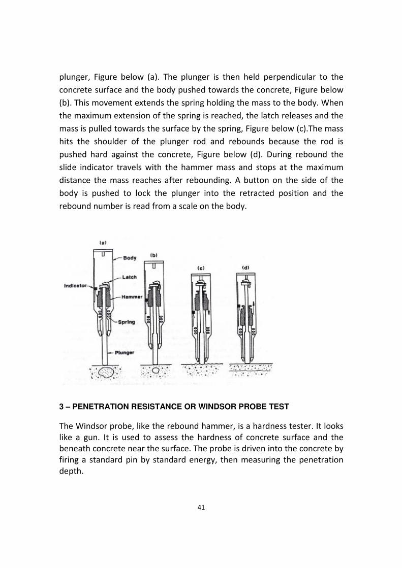
41
plunger, Figure below (a). The plunger is then held perpendicular to the
concrete surface and the body pushed towards the concrete, Figure below
(b). This movement extends the spring holding the mass to the body. When
the maximum extension of the spring is reached, the latch releases and the
mass is pulled towards the surface by the spring, Figure below (c).The mass
hits the shoulder of the plunger rod and rebounds because the rod is
pushed hard against the concrete, Figure below (d). During rebound the
slide indicator travels with the hammer mass and stops at the maximum
distance the mass reaches after rebounding. A button on the side of the
body is pushed to lock the plunger into the retracted position and the
rebound number is read from a scale on the body.
3 – PENETRATION RESISTANCE OR WINDSOR PROBE TEST
The Windsor probe, like the rebound hammer, is a hardness tester. It looks
like a gun. It is used to assess the hardness of concrete surface and the
beneath concrete near the surface. The probe is driven into the concrete by
firing a standard pin by standard energy, then measuring the penetration
depth.

42
4. ULTRASONIC TESTING
The methodology of UPV is based at time monitoring of pulses in a section
of the object. The UPV will depend on the density and the elastic properties
of the material in study. The quality of many materials of construction is
related with its rigidity, the measure of the UPV can be used to measure
the concrete structures quality, estimate the mechanical properties, the
compressive strength and the modulus of elasticity.
The Instrument generates pulses of ultrasonic frequency, which are
coupled into the concrete specimen under test by the transmitting
transducer. The receiving transducer is used to detect these pulses & to
convert them back into electrical pulses.

43
Picture 1. UPVatConcrete.
Ultrasonic is a non-destructive test performed by sending high-frequency
wave (over 20 kHz) through the media. By following the principle that wave
travels faster in denser media than in the looser one, engineer can interpret
the quality of material from velocity of the wave. This can be applied to
several types of materials such as concrete, wood, etc.
Portable Ultrasonic Non-destructive Digital Indicating Test (PUNDIT) is used
for this purpose. Two transducers, one as transmitter and the other one as
receiver, are used to send and receive 54 kHz frequency.
Velocity of the wave is measured by placing two transducers, one on each
side of concrete element. Apply thin grease layer to the surface of
transducer in order to ensure effective transfer of the wave between
concrete and transducer.
The time which the wave takes to travel is read out from PUNDIT’s display
and velocity of the wave can be computed as follows:
V = L / T ………………. (1)
Where
V = Velocity of the wave, km/sec.
L = Distance between transducers, mm.
T = Travelling time, 10-6
sec.
Placing transducers to the concrete element can be done in three formats,
as shown below.

44
(a): Direct transmission. B)Semi-direct transmission.
(c): Indirect or surface transmission.
Velocity of pulse in concrete decreases if there is any abnormalities such as
air void, cracks, or any other foreign materials. Integrity of concrete can be
interpreted from velocity of pulse as follow:
Pulse velocity, km/sec Condition
Over 4.0 Good
3.6 - 4.0 Some defection
Below 3.6 Defected
Factors Affecting the Test Result
• Size of coarse aggregate.

45
• Water-cement ratio.
• Admixtures.
• Age of concrete.
• Water content.
• Path length.
• Steel reinforcement.
• Sample size.
• Probes touch to sample.
5– Core Test
Core test is carried out according to ASTM C42.
This test method provides standardized procedures for obtaining and
testing specimens to determine the compressive, splitting tensile and
flexural strength of in-place concrete.
Generally, test specimens are obtained when doubt exists about the in-
place concrete quality due either to low strength test results during
construction or signs of distress in the structure. Another use of this
method is to provide strength information on older structures.
Concrete strength is affected by the location of the concrete in a structural
element, with the concrete at the bottom tending to be stronger than the
concrete at the top. Core strength is also affected by core orientation
relative to the horizontal plane of the concrete as placed, with strength
tending to be lower when measured parallel to the horizontal plane. These
factors shall be considered in planning the locations for obtaining concrete
samples and in comparing strength test results.
The strength of concrete measured by tests of cores is affected by the
amount and distribution of moisture in the specimen at the time of test.
There is no standard procedure to condition a specimen that will ensure
that, at the time of test, it will be in the identical moisture condition as
concrete in the structure. The moisture conditioning procedures in this test
method are intended to provide reproducible moisture conditions that
minimize within-laboratory and between-laboratory variations and to
reduce the effects of moisture introduced during specimen preparation.
The measured compressive strength of a core will generally be less than
that of a corresponding properly molded and cured standard cylinder

46
tested at the same age. For a given concrete, however, there is no unique
relationship between the strengths of these two types of specimens. The
relationship is affected by many factors such as the strength level of the
concrete, the in-place temperature and moisture histories, the degree of
consolidation, batch-to-batch variability, the strength-gain characteristics of
the concrete, the condition of the coring apparatus, and the care used in
removing cores.
According to ACI 318, the concrete represented by the cores is considered
structurally adequate if the average strength of three cores is at least 85 %
of the specified strength and no single core strength is less than 75 % of the
specified strength.
The apparent compressive strength of concrete as measured by a core is
affected by the length-diameter ratio (L/D) of the core as tested and this
must be considered in preparing core specimens and evaluating test
results.
Cracks Repairlec. 12
Cracks repair is done to back the structure to the efficiency in performance,
use and apparent. During repair process, a structure may need strengthening
measures to improve its efficiency comparing to its formal situation.There
are many methods to repair cracks. The suitable method is chosen according
to the available technology, structure importance and cost.
Among the most important methods are:

47
1. Epoxy Injection:this method is often used to seal and repair the narrow
cracks of width (1–3) mm. As well as, it is used to repair the pre-cast
concrete units, such as beams and piles or the insitu cast structural parts such
as columns and slabs….etc. this method processes are:
o The crack is well cleaned by compressed air, water or brushing or
even using solvents sometimes.
o Close and seal crack surface by epoxy or special tap or another thing.
o Making holes along crack length ad fix tubes in these holes to use
them in injection process. Holes diameter and distance between holes
depend factors, among which, crack type and width, epoxy type and
viscosity and injection device type…etc. anyway, the distance
between two holes is (0.5–1) m.
o Epoxy is mixed and prepared according to producer instructions.
o Epoxy injection through the fixed tubes with alternating pressure.
Injection continues in the 1st hole till the epoxy comes out from the
following hole, or thepressure becomes stable and no more epoxy is
to be injected. And so on the process goes on. When the crack is
perpendicular or inclined, the injection process starts from down
upwards. When the crack is horizontal, the injection process is
alternatively right and left.
o The surface seal and tubes are removed.
o Crack is treated according to used material producer directions.
o The surface is refinishing.
2. Stitching: this method is for the cracks occur in tension zone; tensile
stresses on both crack sides. Crack sealing is not enough in such case (crack
will appear again after repair). This method is:
o Making holes on both crack sides with depth not less than crack depth
and distance of about 30 cm from crack to hole. And making groove
between the two holes. This is to be done each (25 to 50) cm along the
crack as it is in the drawing below.
o The groove is to be cleaned well.

48
o Putting a channel shape steel clipsso that each of the two vertical parts
in a hole and the horizontal part in the groove.
o Clips are to be fixed in holes by epoxy or un–shrinkable mortar.
o Clips are to be put in right places to insure the resistance of tensile
stress.
o The distance between two clips is to be minimized at crack end.
o Holes, grooves and crack are to be sealed and finished properly.
o It is preferable to make stitching from both concrete surfaces so as the
structure movement does not bend the clips.
o Stitching process prevents crack propagation but does not close it.
o Crack is to be repaired before stitching when there is moisture to
protect clips against corrosion. When there is movement, stitching is
to be done first. Otherwise, crack repair materials will be crumbled.
o The last step is the fishing.
Fig (3) shows crack stitching method.

49
3. Drilling and Plugging: This method is used where water is in touch
with structure parts to prevent water from passing through cracks, for
example, in swimming pools, fountains and reservoirs.
When cracks run in reasonable straight lines and are accessible at one end,
drilling down the length of the crack and grouting it to form to repair them,
as it is the case in retaining walls. Drilling a hole wider a little bit than crack
width (diameter of 50 to 75 mm) and with crack depth. Repair steps are:
o Crack is to be cleaned and filled with grout (grouting material must
be of low modulus of elasticity).
o Place reinforcement bars (of predetermined sizes and lengths) in
them to stitch across the cracks.
Hole drilledin stemofwall.Centeredon
andfollowingdowncrack.Sizeof holedependson
widthofcrack.Use2”to 2-1/2”minimumdiameter.
Fig (4) drilling and plugging.

50
4. Polymer Impregnation:it’s a costly method used in specific placessuch
as reservoir of chemicals. The process is inserting polymer of low viscosity
in cracks. By heating, the polymer will be strong, durable and elastic
material which improves concrete properties. In this method, cracks must
be dried.
The large voids can be filled by aggregate in the compression zone before
inserting the polymer.
5. Dry Backing:this method is used to seal the narrow cracks, not
for active cracks. This method is:
o Widening the crack to 25mm and with depth 25mm
before repair, crack is to be as (V) shape.
o Cleaning and drying the crack.
o Using mortar (1:1) or polymer. Then mortar (1:3) on
condition that sand passes through sieve no. 16. Mortar water is to
be minimized as much as possible. Mortar is to be put with pressing
to bond it to old concrete.
6 Flexible Sealing: this method is used with narrow cracks. Cracks width
is changed with seasons. It can be used when there are cracks between
two expansion joints. The method is:
o Cleaning the crack by water or compressed air, then filled
by elastic material such as mastic. The crack is to be widened so as
to be similar to the expansion joints.
o Isolated material is to be put in the bottom to let the
mastic changes its shape without concentrating stresses in the
bottom. The isolation material is not to be bondto mastic.
This is an economical method can be used in reservoirs, slabs and other
areas which are not exposed to mechanical forces.
51
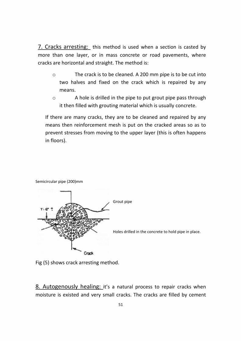
7. Cracks arresting: this method is used when a section is casted by
more than one layer, or in mass concrete or road pavements, where
cracks are horizontal and straight. The method is:
o The crack is to be cleaned. A 200 mm pipe is to be cut into
two halves and fixed on the crack which is repaired by any
means.
o A hole is drilled in the pipe to put grout pipe pass through
it then filled with grouting material which is usually concrete.
If there are many cracks, they are to be cleaned and repaired by any
means then reinforcement mesh is put on the cracked areas so as to
prevent stresses from moving to the upper layer (this is often happens
in floors).
Semicircular pipe (200)mm
Grout pipe
Holes drilled in the concrete to hold pipe in place.
Fig (5) shows crack arresting method.
8. Autogenously healing: it’s a natural process to repair cracks when
moisture is existed and very small cracks. The cracks are filled by cement
52
hydration products (gel). Cracks may be filled by CaCO3 results from the
reaction between Ca(OH)2 from cement hydration and CO2 from
atmosphere. CaCO3 precipitates with Ca(OH)2 and they grow and fill the
crack. This gains some strength to resist tensile stresses.
No healing for active cracks.As well as, no healing where there is flowing
water, it washes calcium hydroxide and calcium carbonate.
9. over lays and surface treatment: when there are many cracks in a
floor, the methods are either:
Neglecting the old concrete and consider it as a base then cast new
concrete layer over it.
Or
Putting stress tensor layer then overlay thin layerso as the new and old
layers act together as one unit.
10. Grouting:In structures such as dams and large foundations,wide and
deep cracks may take place and extend deep in soil for long distances. The
case is impossible to be solved by epoxy injection. Here, injection of cheap
material is used, such as cement mortar or mud.
Note: there are many other methods.

53
Repair of R.C ColumnsLec.13
R.C Columns are so important that the deterioration of any of them may
cause total or partial failure. All sides (designer, maintenance team and
users) must pay their attention to this fact.
R.C. Column Types:
A. Tied Column: square, rectangular or circular section, in which main
reinforcement bars are fixed by separated ties.
B. Spirally Reinforced Column: circular section , in which main
reinforcement bars are arranged on circle shape and surrounded by spiral
tie.
There is another type called composite column. It consists of steel section
with or without reinforcement bars to bear most of load and concrete to
protect steel against fire.

54
The common defects in R.C. columns:
1. Superficial or deep cracks in concrete.
2. Deterioration in concretecover.
3. Cracks parallel to main reinforcement.
4. Partsof concrete separated due to buckling.
5. Edges crushing.
6. Others depend on column place.
Causes of defects and deterioration in columns:
1. Causes belong to design; reinforcement quantity, column dimensions,
distance between stirrups and concrete designed strength.
2. Causes belong to execution; materials quality, perpendicularity, concrete
quality and others.
3. Causes belong to use; overload moisture, steel corrosion and others.
4. Accidents; earthquake, fire, impact and explosion.
Repair of R.C. Columns:
The repair of R.C. Columns must be done quickly without delay. There are
many methods to repair them. Each method must ensure:
1. Either to repair the column and make it efficient in function and
appearance.
2. Or to repair the column and increase its efficiency for the new function
and maintaining good appearance.
3. Removing the damaged concrete and evaluating the case.
4. Straightening the column that the deviation in column leads to change
the level of beams and slabs.
55
5. Thinking in strengthened method. Strengthening may be done before or
after repair process. In this example, strengthening is after repair.
Lec. 14
6. Cleaning of damaged concrete and adjusting steel reinforcement and
cleaning cracks by steel brush, compressed air and water.
7. Cracks are to be repaired. The repair is often done by epoxy injection.
8. Casting new concrete to substitute the removed concrete, taking the
following in consideration:
A.The same materials types are to be used (cement, aggregate).
B. the concrete mix is to be well designed so as to insure the needed
compression strength.
C. Small maximum aggregate size of gravel is to be used.
D. Admixture is to be used to insure good bond between new and old
concrete.
E. Concreting is to start from the down of the column and up on stages.
F. Concrete curing.
9. Using steel sections (angle and plate) to surround the column and
strengthen it.
_,\.jj\

56