upp gemini fittings
TRANSCRIPT

UPP® GEMINI® FITTINGSINSTALLATION GUIDE
The information in this publication is provided for reference only. While every effort has been made to ensure the reliability and accuracy of the information contained in this manual at the time of printing, we recommend that you refer to “franklinfueling.com” for the most current version of this manual. All product specifications, as well as the information contained in this publication, are subject to change without notice. Franklin Fueling Systems does not assume responsibility and expressly disclaims liability for loss, damage, or expense arising out of, or in any way connected with, installation, operation, use, or maintenance by using this manual. Franklin Fueling Systems assumes no responsibility for any infringement of patents or other rights of third parties that may result from use of this manual or the products. We make no warranty of any kind with regard to this material, including, but not limited to, the implied warranties of merchantability and fitness for a particular purpose.
Copyright © 2021 Franklin Fueling Systems, LLC, Madison, WI 53718. All world rights reserved. No part of this publication may be stored in a retrieval system, transmitted, or reproduced in any way, including, but not limited to, photocopy, photograph, magnetic, or other record, without the prior written permission of Franklin Fueling Systems.
For technical assistance, please contact:
franklinfueling.com3760 Marsh Rd. • Madison, WI 53718 • USATel: USA & Canada +1 800 225 9787 • Fax: +1 608 838 6433Tel: UK +44 (0) 1473 243300 • Tel: Mex 001 800 738 7610Tel: DE +49 6571 105 380 • Tel: CH +86 10 8565 4566
Gemini and UPP are registered trademarks of Franklin Electric Company, Inc.
408001014 r6
Conventions used in this manualThis manual includes safety precautions and other important information presented in the following format:
NOTE: This provides helpful supplementary information.
IMPORTANT: This provides instructions to avoid damaging hardware or a potential hazard to the environment, for example: fuel leakage from equipment that could harm the environment.
CAUTION: This indicates a potentially hazardous situation that could result in minor or moderate injury if not avoided. This may also be used to alert against unsafe practices.
WARNING: This indicates a potentially hazardous situation that could result in severe injury or death if not avoided.
DANGER: This indicates an imminently hazardous situation that will result in death if not avoided.
Operating precautionsFranklin Fueling Systems (FFS) equipment is designed to be installed in areas where volatile liquids such as gasoline and diesel fuel are present. Working in such a hazardous environment presents a risk of severe injury or death if you do not follow standard industry practices and the instructions in this manual. Before you work with or install the equipment covered in this manual, or any related equipment, read this entire manual, particularly the following precautions:
IMPORTANT: To help prevent spillage from an underground storage tank, make sure the delivery equipment is well-maintained, that there is a proper connection, and that the fill adaptor is tight. Delivery personnel should inspect delivery elbows and hoses for damage and missing parts.
CAUTION: Use only original FFS parts. Substituting non-FFS parts could cause the device to fail, which could create a hazardous condition and/or harm the environment.
WARNING: Follow all codes that govern how you install and service this product and the entire system. Always lock out and tag electrical circuit breakers while installing or servicing this equipment and related equipment. A potentially lethal electrical shock hazard and the possibility of an explosion or fire from a spark can result if the electrical circuit breakers are accidentally turned on while you are installing or servicing this product. Refer to this manual (and documentation for related equipment) for complete installation and safety information.
WARNING: Before you enter a containment sump, check for the presence of hydrocarbon vapors. Inhaling these vapors can make you dizzy or unconscious, and if ignited, they can explode and cause serious injury or death. Containment sumps are designed to trap hazardous liquid spills and prevent environmental contamination, so they can accumulate dangerous amounts of hydrocarbon vapors. Check the atmosphere in the sump regularly while you are working in it. If vapors reach unsafe levels, exit the sump and ventilate it with fresh air before you resume working. Always have another person standing by for assistance.
WARNING: Follow all federal, state, and local laws governing the installation of this product and its associated systems. When no other regulations apply, follow NFPA codes 30, 30A, and 70 from the National Fire Protection Association. Failure to follow these codes could result in severe injury, death, serious property damage, and/or environmental contamination.
WARNING: Always secure the work area from moving vehicles. The equipment in this manual is usually mounted underground, so reduced visibility puts service personnel working on it in danger from moving vehicles that enter the work area. To help prevent this safety hazard, secure the area by using a service truck (or some other vehicle) to block access to the work area.
DANGER: Make sure you check the installation location for potential ignition sources such as flames, sparks, radio waves, ionizing radiation, and ultrasound sonic waves. If you identify any potential ignition sources, you must make sure safety measure are implemented.
1
IntroductionThe Gemini® line of secondary containment fittings use the UPP® electrofusion process to create permanent connections in UPP® piping. Compared with previous fittings, the Gemini design reduces the number of fittings needed and allows the primary fittings to be fully accessible for testing before the secondary is welded.
Tools Required• UPP® Welder• UPP® Adjustable Rotary or Rotary Scraper• Marker Pen• Lint-free/microfiber rags• Tape Measure• UPP® Pipe Cutter• Acetone or isopropyl alcohol (95% or greater)
Storage and Handling• Avoid mechanical damage.• UPP® fittings: All electrofusion fittings are packed in heat-sealed polyethylene bags and
delivering in cardboard cartons.• All fittings (electrofusion fittings, for example) must be stored in their packaging
(polyethylene bags/cartons) and in a dry area, away from direct sunlight, until ready for use to prevent any contamination or oxidation.
Welding LeadsThe welding leads used for these fittings are 4 mm, 4 amp red leads.
ContentsIntroduction ...................................................................................................................................1
Tools Required ............................................................................................................................1Storage and Handling .................................................................................................................1Welding Leads .............................................................................................................................1
Installing a 45º Elbow ....................................................................................................................2Parts List ......................................................................................................................................2
Installing an In-Line Connection ....................................................................................................4Installing a 90º Fitting ....................................................................................................................6Installing a Tee Fitting ....................................................................................................................9Testing ............................................................................................................................................12Consequences of poor fitting preparation ....................................................................................13

2
Installing a 45º ElbowNOTE: Refer to FFS manual 408001007 for information about the electrofusion process. Refer to the UPP® Piping Installation Guide (pt# 408001016) for piping installation and pressure testing information.
Parts ListParts Lists
Item qty 40/32mm 63/50 mm 75/63 mm 110/90 mm 125/110 mm1 1 04-032-EIF 04-050-EIF 04-063-EIF 04-090-EIF 04-110-EIF
2 1 G4-040-032 G4-063-050 G4-075-063 G4-110-090 G4-125-110
3 2 001-032-XXX 001-050-XXX 001-063-XXX 001-090-XXX 001-110-XXX
4 2 000-040-XXX-SC-E 000-063-XXX-SC-E 000-075-XXX-SC-E 000-110-XXX-SC-E 000-125-XXX-SC-E
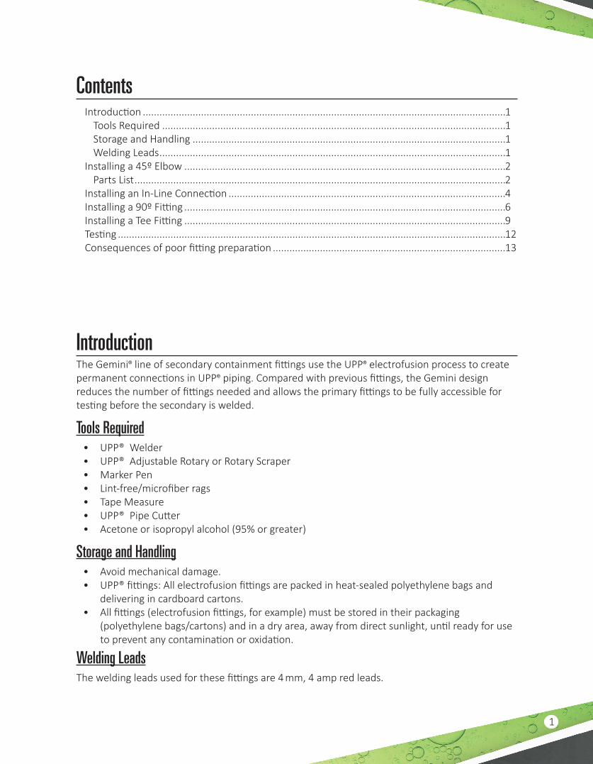
NOTE: Gemini® fittings use locking tabs to hold the sides together securely. A small screwdriver can be used to lift the tabs slightly to assist engagement.
1. Cut back secondary pipe by dimension A in the following table.
Referenced Dimensions mm (in)Stock Code A B C DG4-125-110 77 (3.0) 68 (2.7) 71 (2.8) 48 (1.9)
G4-110-090 67 (2.6) 65 (2.6) 61 (2.4) 45 (1.8)
G4-075-063 51 (2.0) 65 (2.6) 45 (1.8) 45 (1.8)
G4-063-050 47 (1.9) 65 (2.6) 41 (1.6) 45 (1.8)
G4-040-032 41 (1.6) 66 (5.6) 35 (1.4) 46 (1.8)
2. Scrape pipes as shown below: primary dimension A, secondary dimension B.
C DA B
Primary PipeSecondary Pipe
SocketInsertion Depth
G4 Sliding CouplerWelded Position
Mark Pipe
Scraped Region
3. Clean pipe ends and components. Clean secondary pipe ends by at least 300 mm (12").
IMPORTANT: Wear nitrile gloves when you use any of the following solvents, and refer to the SDS for the solvent for additional safety information.
4. Soak a lint-free cloth in one of the following solvents: isopropyl alcohol (95% or greater) or acetone.

3
NOTE: The electrofusion welding fittings and UPP® piping need to be cleaned before welding even if it was cleaned recently. Do NOT USE solvents that leave an oily film on the joining surface such as turpentine, petrol or synthetic dilutants.
5. When cleaning Tee, 45o and 90o elbows, the pipes and fittings should be cleaned all-around before welding. The surfaces to be cleaned include:
• All scraped areas of pipes and fittings.• The inside of electrofusion fittings and welding couplers.• Welding area on Gemini® fitting and pipe.
6. Clean the areas shown below. Make sure they are free from dust, debris, moisture, and water.
7. Mark insertion depth on primary pipe dimension C and secondary pipe dimension D.
8. Slide secondary components onto secondary pipe.
9. Insert primary pipe into primary elbow as shown below.
>300 mm(12") >300 mm(12")Cleaned Regions
10. Weld primary elbow as per UPP® welding guidelines and allow to cool.
11. Pressure / Leak test primary line once line is completed.
NOTE: Secondary components should be welded as soon as possible, and never later than 24 hours after the pipe has been installed, unless the prepared areas are protected using cling film and are re-cleaned before final assembly and welding. FFS recommends leaving the Gemini® components assembled at all times before the final welding to protect the central weld area and prevent environmental damage.
12. Ensure secondary pipe and secondary coupling components are clean. If unsure - Re-clean.
13. Slide secondary components together engaging locking device and weld as per Figure 5.• a-Socket• b-Coupler to pipe
4
Lock TabsSmall Screwdriver
a. 1st Weld: Socket
b. 2nd Weld: Coupler to Pipe(Optional use of bridging leads)
Installing an In-Line ConnectionThe same 45º secondary fitting is used in straight-thru connections by rotating one secondary fitting.
Parts ListsItem qty 40/32mm 63/50 mm 75/63 mm 110/90 mm 125/110 mm
1 1 02-032-L 02-050-L 02-063/02-063-L 02-090-L 02-110-L
2 1 G4-040-032 G4-063-050 G4-075-063 G4-110-090 G4-125-110
3 2 001-032-XXX 001-050-XXX 001-063-XXX 001-090-XXX 001-110-XXX
4 2 000-040-XXX-SC-E 000-063-XXX-SC-E 000-075-XXX-SC-E 000-110-XXX-SC-E 000-125-XXX-SC-E
C DA B
Primary PipeSecondary Pipe
SocketInsertion Depth
G4 Sliding CouplerWelded Position
Mark Pipe
Scraped Region

5
1. Cut back secondary pipe by dimension A in in the following table.
Referenced Dimensions mm [in]Stock Code A B C D
G4-125-110 81[3.2] 100[3.9] 71[2.8] 80[3.2]
G4-110-090 72[2.8] 96[3.8] 62[2.4] 76[3.0]
G4-075-063 (for 02-063 primary coupler)
40[1.6] 91[3.6] 30[1.2] 71[2.8]
G4-075-063 (for 02-063-L primary coupler)
57[2.3] 75[3.0] 47[1.9] 55[2.2]
G4-063-050 53[2.1] 82[3.2] 43[1.7] 62[2.5]
G4-040-032 41[1.6] 74[2.9] 35[1.4] 54[2.1]
2. Scrape the pipes according to the above table: primary dimension A, secondary dimension B.
3. Clean the scraped pipe ends and components. Clean secondary pipe ends by at least 300 mm (12").
IMPORTANT: Wear nitrile gloves when you use any of the following solvents, and refer to the SDS for the solvent for additional safety information.4. Soak a lint-free cloth in one of the following solvents: isopropyl alcohol (95% or greater) or
acetone.NOTE: The electrofusion welding fittings and UPP® piping need to be cleaned before welding even if it was cleaned recently. Do NOT USE solvents that leave an oily film on the joining surface such as turpentine, petrol or synthetic dilutants.5. When cleaning Tee, 45o and 90o elbows, the pipes and fittings should be cleaned all-around
before welding. The surfaces to be cleaned include:• All scraped areas of pipes and fittings.• The inside of electrofusion fittings and welding couplers.• Welding area on Gemini® fitting and pipe.
6. Clean the areas shown below. Ensure they are free from dust, debris, moisture, and water.
7. Clean scraped pipe ends and components. Clean secondary pipe ends by at least 300 mm (12").
8. Mark insertion depth on primary pipe dimension “C” and secondary pipe dimension “D”9. Slide secondary components onto secondary pipe.
10. Insert primary pipe into primary coupler as shown below.
6
>300 (12")
>300 (12")
Cleaned Regions
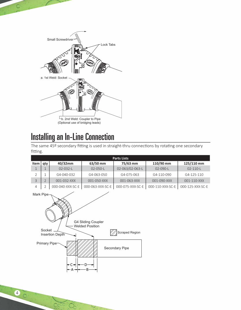
11. Weld the primary coupler according to UPP® welding guidelines, and allow to cool.12. Pressure test primary line once line is completed.NOTE: Secondary components should be welded as soon as possible, and never later than 24 hours after the pipe has been installed, unless the prepared areas are protected using cling film and are re-cleaned before final assembly and welding. FFS recommends leaving the Gemini® components assembled at all times before the final welding to protect the central weld area and prevent environmental damage.
13. Ensure secondary pipe and secondary components are clean. If unsure, re-clean.
14. Slide secondary components together engaging locking device and weld as shown below.a. 1st Weld: Socket
b. 2nd Weld: Coupler to Pipe(Optional use of bridging leads)
15. Test secondary Piping once all Gemini® fittings are completed and cooled for 1.5 hours. Test secondary per UPP® piping and Gemini® fittings following the testing process in this manual.
Installing a 90º FittingParts List
Item qty 40/32mm 63/50mm 75/63mm 110/90mm 125/110mm
1 1 03-032-EIF 03-050-EIF 03-063-EIF 03-090-EIF 03-110-EIF
2 1 G3-040-032 G3-063-050 G3-075-063 G3-110-090 G3-125-110
3 2 001-032-XXX 001-050-XXX 001-063-XXX 001-090-XXX 001-110-XXX
4 2 000-040-XXX-SC-E 000-063-XXX-SC-E 000-075-XXX-SC-E 000-110-XXX-SC-E 000-125-XXX-SC-E
Table 6: 90º Reference Dimensions
7
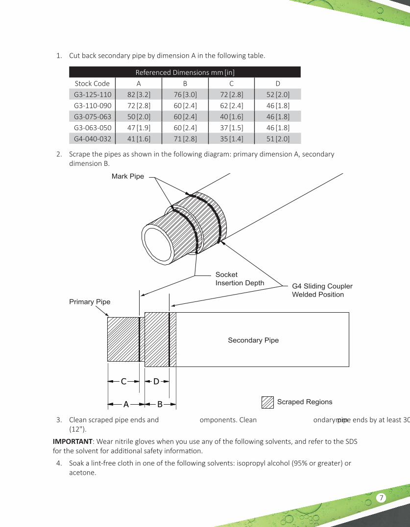
1. Cut back secondary pipe by dimension A in the following table.
Referenced Dimensions mm [in]Stock Code A B C DG3-125-110 82 [3.2] 76 [3.0] 72 [2.8] 52 [2.0]G3-110-090 72 [2.8] 60 [2.4] 62 [2.4] 46 [1.8]G3-075-063 50 [2.0] 60 [2.4] 40 [1.6] 46 [1.8]G3-063-050 47 [1.9] 60 [2.4] 37 [1.5] 46 [1.8]G4-040-032 41 [1.6] 71 [2.8] 35 [1.4] 51 [2.0]
2. Scrape the pipes as shown in the following diagram: primary dimension A, secondary dimension B.
C
A B
D
Primary Pipe
Secondary Pipe
Scraped Regions
SocketInsertion Depth G4 Sliding Coupler
Welded Position
Mark Pipe
3. Clean scraped pipe ends and components. Clean secondary pipe ends by at least 300 mm (12").
IMPORTANT: Wear nitrile gloves when you use any of the following solvents, and refer to the SDS for the solvent for additional safety information.
4. Soak a lint-free cloth in one of the following solvents: isopropyl alcohol (95% or greater) or acetone.

8
NOTE: The electrofusion welding fittings and UPP® piping need to be cleaned before welding even if it was cleaned recently. Do NOT USE solvents that leave an oily film on the joining surface such as turpentine, petrol or synthetic dilutants.
5. When cleaning Tee, 45o and 90o elbows, the pipes and fittings should be cleaned all-around before welding. The surfaces to be cleaned include:• All scraped areas of pipes and fittings.• The inside of electrofusion fittings and welding couplers.• Welding area on Gemini® fitting and pipe.
6. Clean the areas shown below. Make sure they are free from dust, debris, moisture, and water.
7. Mark insertion depth on primary pipe dimension C and secondary pipe dimension D.
Referenced Dimensions mm [in]Stock Code A B C DG3-125-110 82 [3.2] 76 [3.0] 72 [2.8] 52 [2.0]G3-110-090 72 [2.8] 60 [2.4] 62 [2.4] 46 [1.8]G3-075-063 50 [2.0] 60 [2.4] 40 [1.6] 46 [1.8]G3-063-050 47 [1.9] 60 [2.4] 37 [1.5] 46 [1.8]G4-040-032 41 [1.6] 71 [2.8] 35 [1.4] 51 [2.0]
8. Slide secondary components onto the secondary pipe.
9. Insert primary pipe into primary elbow as shown below. Dry fit the Gemini® fitting to ensure proper orientation before you weld the primary fitting.
>300mm (12")>300mm (12")
Cleaned Regions
Figure 12: Weld Primary10. Weld the primary elbow according to UPP® welding guidelines, and allow it to cool.
11. Pressure test the primary line once the line is completed.

9
NOTE: Secondary components should be welded as soon as possible, and never later than 24 hours after the pipe has been installed, unless the prepared areas are protected using cling film and are re-cleaned before final assembly and welding. FFS recommends leaving the Gemini® components assembled at all times before the final welding to protect the central weld area and prevent environmental damage.
12. Make sure the secondary pipe and secondary fittings components are clean. If you are unsure, re-clean.
13. Slide the secondary components together. Engage the locking device, and weld as shown below.
1st Weld, Socket
2nd weld, Coupler to Pipe(Optional use of bridging leads)
14. Test secondary Piping once all Gemini® fittings are completed and cooled for 1.5 hours. Test secondary per UPP® piping and Gemini® fittings following the testing process in this manual.
Installing a Tee FittingParts List
Item qty 40/32mm 63/50mm 75/63mm 110/90mm1 1 02-032-L 02.50 02.63 02-090
2 1 08-032-EIF 08-050-EIF-S 08-063-EIF-S 08-090-EIF-S
3 1 G3-040-032 G8-063-050 G8-075-063 G8-110-090
4 3 001-032-XXX 001-050-XXX-E 001-063-XXX-E 01-110-XXX-E
5 3 000-040-XXX-SC-E 000-063-XXX-SC-E 000-075-XXX-SC-E 000-110-XXX-SC-E
3
5
4
1
2
5 4 54
Y
Z
X
10
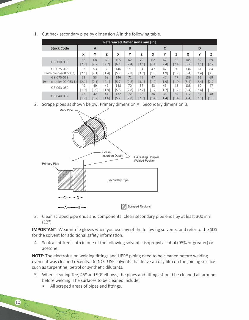
1. Cut back secondary pipe by dimension A in the following table.
Referenced Dimensions mm [in]Stock Code A B C D
X Y Z X Y Z X Y Z X Y Z
G8-110-09068
[2.7]68
[2.7]68
[2.7]155 [6.1]
62 [2.4]
79 [3.1]
62 [2.4]
62 [2.4]
62 [2.4]
145 [5.7]
52 [2.1]
69 [2.7]
G8-075-063 (with coupler 02-063)
53 [2.1]
53 [2.1]
36 [1.4]
146 [5.7]
71 [2.8]
94 [3.7]
47 [1.9]
47 [1.9]
30 [1.2]
136 [5.4]
61 [2.4]
84 [3.3]
G8-075-063 (with coupler 02-063-L)
53 [2.1]
53 [2.1]
53 [2.1]
146 [5.7]
71 [2.8]
79 [3.1]
47 [1.9]
47 [1.9]
47 [1.9]
136 [5.4]
61 [2.4]
69 [2.7]
G8-063-05049
[1.9]49
[1.9]49
[1.9]148 [5.8]
70 [2.8]
57 [2.2]
43 [1.7]
43 [1.7]
43 [1.7]
138 [5.4]
60 [2.4]
47 [1.9]
G8-040-03242
[1.7]42
[1.7]41
[1.6]132 [5.2]
72 [2.8]
68 [2.7]
36 [1.4]
36 [1.4]
35 [1.4]
112 [4.4]
52 [2.1]
48 [1.9]
2. Scrape pipes as shown below: Primary dimension A, Secondary dimension B.
C
A B
D
Primary Pipe
Secondary Pipe
Scraped Regions
SocketInsertion Depth G4 Sliding Coupler
Welded Position
Mark Pipe
3. Clean scraped pipe ends and components. Clean secondary pipe ends by at least 300 mm (12").
IMPORTANT: Wear nitrile gloves when you use any of the following solvents, and refer to the SDS for the solvent for additional safety information.
4. Soak a lint-free cloth in one of the following solvents: isopropyl alcohol (95% or greater) or acetone.
NOTE: The electrofusion welding fittings and UPP® piping need to be cleaned before welding even if it was cleaned recently. Do NOT USE solvents that leave an oily film on the joining surface such as turpentine, petrol or synthetic dilutants.
5. When cleaning Tee, 45o and 90o elbows, the pipes and fittings should be cleaned all-around before welding. The surfaces to be cleaned include:• All scraped areas of pipes and fittings.
11
• The inside of electrofusion fittings and welding couplers.• Welding area on Gemini® fitting and pipe.
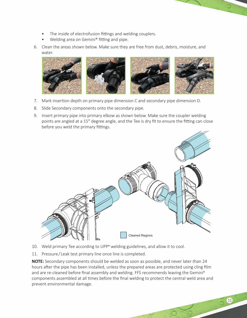
6. Clean the areas shown below. Make sure they are free from dust, debris, moisture, and water.
7. Mark insertion depth on primary pipe dimension C and secondary pipe dimension D.
8. Slide Secondary components onto the secondary pipe.
9. Insert primary pipe into primary elbow as shown below. Make sure the coupler welding points are angled at a 15° degree angle, and the Tee is dry fit to ensure the fitting can close before you weld the primary fittings.
Cleaned Regions
10. Weld primary Tee according to UPP® welding guidelines, and allow it to cool.
11. Pressure / Leak test primary line once line is completed.
NOTE: Secondary components should be welded as soon as possible, and never later than 24 hours after the pipe has been installed, unless the prepared areas are protected using cling film and are re-cleaned before final assembly and welding. FFS recommends leaving the Gemini® components assembled at all times before the final welding to protect the central weld area and prevent environmental damage.
12
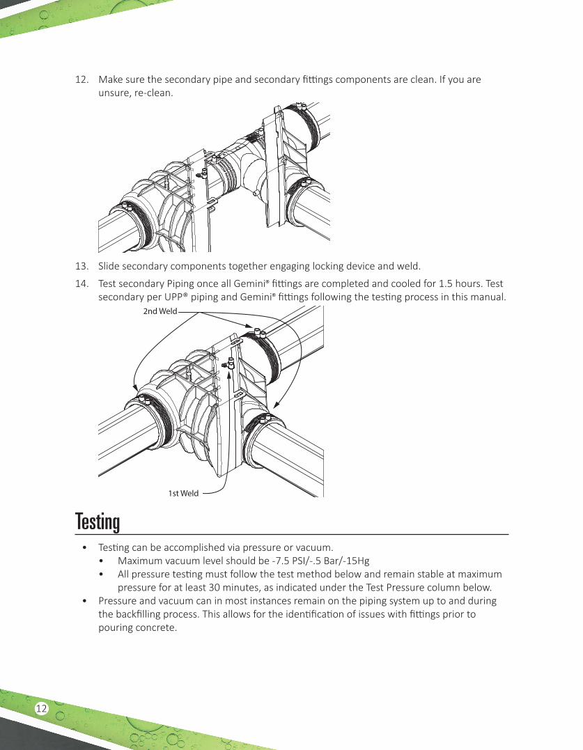
12. Make sure the secondary pipe and secondary fittings components are clean. If you are unsure, re-clean.
13. Slide secondary components together engaging locking device and weld.
14. Test secondary Piping once all Gemini® fittings are completed and cooled for 1.5 hours. Test secondary per UPP® piping and Gemini® fittings following the testing process in this manual.
1st Weld
2nd Weld
Testing• Testing can be accomplished via pressure or vacuum.
• Maximum vacuum level should be -7.5 PSI/-.5 Bar/-15Hg• All pressure testing must follow the test method below and remain stable at maximum
pressure for at least 30 minutes, as indicated under the Test Pressure column below.• Pressure and vacuum can in most instances remain on the piping system up to and during
the backfilling process. This allows for the identification of issues with fittings prior to pouring concrete.
13
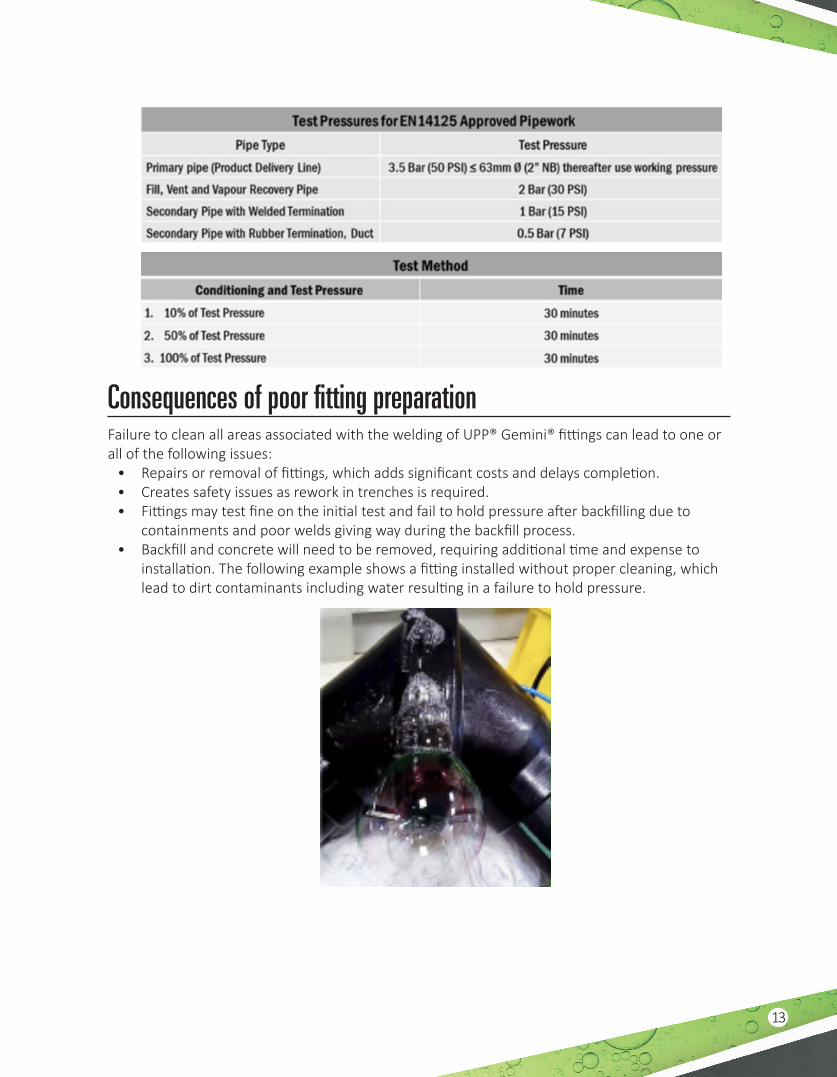
Consequences of poor fitting preparationFailure to clean all areas associated with the welding of UPP® Gemini® fittings can lead to one or all of the following issues:
• Repairs or removal of fittings, which adds significant costs and delays completion.• Creates safety issues as rework in trenches is required.• Fittings may test fine on the initial test and fail to hold pressure after backfilling due to
containments and poor welds giving way during the backfill process.• Backfill and concrete will need to be removed, requiring additional time and expense to
installation. The following example shows a fitting installed without proper cleaning, which lead to dirt contaminants including water resulting in a failure to hold pressure.

408001014 r6