user’s guidesound-better.net/support/manuals/pro/owners_manual_iasys.pdfphone 425-775-8461 • fax...
TRANSCRIPT

Answers,Not Just DataSM
• Crossover Points and Levels• Limiter Settings• Delay Times• System Polarity• Frequency Response• Coherence• Programmable Sweep/Sine/Noise• Spectrum Analysis
Portable, Self-contained, Intuitive,Fast results, Documentation,Rugged, Made in USA
User’s Guide
22410 70th Avenue West • Mountlake Terrace, WA 98043Phone 425-775-8461 • Fax 425-778-3166 • Internet http://www.audiocontrol.com
©1998. All Rights Reserved
P/N: 9130410Rev : 1.15

Phone 425-775-8461 • Fax 425-778-3166
8/15/98

Phone 425-775-8461 • Fax 425-778-3166
8/15/98
Section One WelcomeNew class of audio analysis . . . . . . . . . . . . . . . . . . . . . . . . . . . . . . . . . . . . 1-2
About this guide . . . . . . . . . . . . . . . . . . . . . . . . . . . . . . . . . . . . . . . . . . . . . . . . 1-3
Section Two Iasys OverviewWhat Iasys Does . . . . . . . . . . . . . . . . . . . . . . . . . . . . . . . . . . . . . . . . . . . . . . . .2-1
How It Works . . . . . . . . . . . . . . . . . . . . . . . . . . . . . . . . . . . . . . . . . . . . . . . . . . 2-3
General Iasys test procedure . . . . . . . . . . . . . . . . . . . . . . . . . . . . . . . . . . 2-5
Getting Help . . . . . . . . . . . . . . . . . . . . . . . . . . . . . . . . . . . . . . . . . . . . . . . . . . . 2-6
Section Three Getting StartedA tour of the Front Panel . . . . . . . . . . . . . . . . . . . . . . . . . . . . . . . . . . . . . . . 3-1
A tour of the Back Panel . . . . . . . . . . . . . . . . . . . . . . . . . . . . . . . . . . . . . . 3-3
Making Measurements; procedures, guidelines, advice . . . . . 3-5
Electrical Measurements . . . . . . . . . . . . . . . . . . . . . . . . . . . . . . . . . . . . . . 3-6
Section Four Automatic TestsCrossover Frequency Point . . . . . . . . . . . . . . . . . . . . . . . . . . . . . . . . . . . . .4-1
Crossover Gain Levels . . . . . . . . . . . . . . . . . . . . . . . . . . . . . . . . . . . . . . . . . 4-3
Delay Measurement and Setting . . . . . . . . . . . . . . . . . . . . . . . . . . . . . . 4-5
Checking Acoustic Polarity . . . . . . . . . . . . . . . . . . . . . . . . . . . . . . . . . . . 4-7
Limiter Setting and Verification . . . . . . . . . . . . . . . . . . . . . . . . . . . . . . 4-9
Coherence/Phase Alignment . . . . . . . . . . . . . . . . . . . . . . . . . . . . . . . . 4-11
Equalizable Spectra . . . . . . . . . . . . . . . . . . . . . . . . . . . . . . . . . . . . . . . . . . . 4-15
Section Five Manual TestsPink Noise . . . . . . . . . . . . . . . . . . . . . . . . . . . . . . . . . . . . . . . . . . . . . . . . . . . . . . 5-1
Sine Waves . . . . . . . . . . . . . . . . . . . . . . . . . . . . . . . . . . . . . . . . . . . . . . . . . . . . . . 5-1
Sweep Sine Tests . . . . . . . . . . . . . . . . . . . . . . . . . . . . . . . . . . . . . . . . . . . . . . . 5-3
Section Six Special FunctionsPrinting . . . . . . . . . . . . . . . . . . . . . . . . . . . . . . . . . . . . . . . . . . . . . . . . . . . . . . . . . 6-1
Setting Time, and Date . . . . . . . . . . . . . . . . . . . . . . . . . . . . . . . . . . . . . . . . 6-3
Setting Metric versus English distances . . . . . . . . . . . . . . . . . . . . . . 6-3
Memory Management . . . . . . . . . . . . . . . . . . . . . . . . . . . . . . . . . . . . . . . . 6-5
Section Seven TroubleshootingGain levels and error messages . . . . . . . . . . . . . . . . . . . . . . . . . . . . . . . . . 7-1
Hookup error messages . . . . . . . . . . . . . . . . . . . . . . . . . . . . . . . . . . . . . . . . 7-2
Section Eight SpecificationsHardware specifications . . . . . . . . . . . . . . . . . . . . . . . . . . . . . . . . . . . . . . . . 8-1
Parallel and Serial Pinouts . . . . . . . . . . . . . . . . . . . . . . . . . . . . . . . . . . . . . 8-2
Section Nine Warranty and Service Information
Appendices
Table of Contents
©1997. All Rights Reserved.
Phone 425-775-8461 • Fax 425-778-3166
8/15/98
More Than Just Any Test Instrument
The IasyIasyIasyIasyIasysssss audio analyzer is the result of a extremely dedicated group of
people at AudioControl Industrial with a dream of what a useful but easy
to use test instrument could be. We have almost fifteen man years invested
so far.
It is not the result of our work alone. Substantial credit for the IasyIasyIasyIasyIasysssss
goes to the many audio pioneers over the years who have laid down the
principles embodied within it’s fuzzy logic. In many ways, our job has been to
build the artifical intelligence that hides the technology so you do not have
to worry about it. Particular credit goes to the late Richard Heyser
whose work was not only groundbreaking but lucidly described so others
could understand.
IasyIasyIasyIasyIasysssss started with an examination of what a real time spectrum ana-
lyzer could do and what it could not. As you probably know, we build a lot
of spectrum analyzers, so we are very familiar with them. We drew up our
wish list and the result of that wish list is IasyIasyIasyIasyIasysssss. It helps anybody, like us,
better set the common tools (crossover, delays, limiters, equalizers) that
we have been using for years.
So from the design team of Dwight, Bob, Dennis, Mark , Robin and
myself, we send you onto an adventure of better sounding, faster setup, and
longer lasting sound systems. You not only get our best work but a little bit
of us with each unit.
Sincerely
Tom Walker
President
Section 1 page 1

Phone 425-775-8461 • Fax 425-778-3166
8/15/98
Iasys is a new class of audio measurement and analysis tool. It isextremely sophisticated yet very easy to use. Within the elegant box are
all the parts and knowledge in the form of patent pending hardware andsoftware that you need. The front panel operates as the simplest level of theoperating manual in the sense there are buttons clearly marked for eachfunction. But being simple to use is only one of the many attractions ofIasys (pronounced like “I assist”).
Answers Not Just Data“Answers Not Just Data” is more a mantra than a slogan for Iasys. Run anautomatic test and Iasys gives specific answers for the setting of crossoverpoints, adjusting crossover levels, adjusting delay times, and setting limiters.There are no waterfall graphs to interpret. There are no complicated graphsthat one person might intrepret one way while another person sees some-thing different. The answers from Iasys get you to where you want to gofaster.
It is All HereIasys is self-contained with it’s own operating system, software, and com-puter built in. In it’s rugged metal case, it is ready to go without any otherapparatus. Completely designed and built in the USA by AudioControlIndustrial, Iasys is not vulnerable to unexpected or unwelcome changes ineither hardware or software triggered by some unrelated computer com-pany. This is a reliable, stable instrument that will support you for manyyears to come.
Built on a Solid BaseWe have been building real time spectrum analyzers since the late 1970’s.You probably already own one. The SA-3050 family of analyzers is theworld’s most popular in use daily from major worldwide concerts to moviesoundtracks to White House press conferences. All of our experience withaudio analyzers is built into the new and groundbreaking Iasys. Pleaseexplore the possibilities of Iasys by reading on in this user’s guide.
Welcome
A New Class of System Setup Tool
Section 1 page 2

Phone 425-775-8461 • Fax 425-778-3166
9/15/97
Most of this guide is divided into two page modules. On the leftpage of each module there is a summary of the subject followed by
detailed information on how to perform the test or function which is thesubject of that module. On the right page, usually, you see a set of hookupdiagrams and illustrations of that test or function. The text often continuesbelow the drawings.
The two page format is what you find when you look up most topics. Notonly is this format efficient and clear, it means that each subject standspretty much alone. You can use the table of contents to find a subject andthen learn what you need from the two page instructions and diagrams. Insome modules, you will see references to more information elsewhere in theguide. That said, we still harbor fond hopes that you will read most of thismanual since we have filled it full of hints on how to get the most out ofthe amazing Iasys audio anlyzer.
Module FormatEach two page module is organized with the following sections in this order(unless we thought better of it and used some fuzzy logic):
• summary of the purpose of that module;• for the subject of the module, what Iasys does for you automatically;• instructions on performing a test or function;• hints, cautions, or additional information that helps;• drawings of the display screen with the information you should see;• picture of the front panel section with the relevant buttons; and• diagrams of a common system hookup.
User Guide OrganizationThis guide proceeds from the general to the specific:For Overview Begin with “Iasys Overview” for information specific to Iasys.
Included here is a description of the features (which are unlike anytest instrument you have used before), some basic theory ofoperation, test procedure protocols, and information about gettinghelp
“Getting Started” covers the Iasys front and back panel plus someadvice on making acoustic measurements and loudspeaker analysisin specific.
For Testing “Automatic Tests” refers to the tests for crossovers, limiters, delays,etc, including polarity and coherence that Iasys runs literally atthe push of a button.
“Manual Tests” includes sine, noise, and swept sine tests which areuser controlled.
Support “Special Functions” contains how to print results, changing time,date, english versus metric, and memory management.
“Troubleshooting” is self-explanatory as are the sections on “Speci-fications” and “Warranty and Service Information”.
Introduction
About This Guide
Section 1 page 3

Phone 425-775-8461 • Fax 425-778-3166
9/15/97
Phone 425-775-8461 • Fax 425-778-3166
8/15/98
After making initial tests on the characteristics of the speakers beingmeasured, Iasys recommends the correct crossover frequency point.
This crossover point recommendation takes into consideration the acousti-cal space during the test.
Iasys will automatically• measure the background noise during the first part of the test• set the microphone pre-amps to the correct level• ramp up the test signal to 18 dB above the background, a minimum of
85 dB, or another pre-set level• scan the driver under test before conducting a detailed analysis
Performing a crossover frequency testThis test is completed on individual drivers (or sets of drivers) based uponthe design of the system. For example, with a three-way system, test thelowest driver or group, then the mid-range, and finally the high frequencycomponents.To perform a crossover frequency test:
Connect Iasys output to the amplifier powering the driver (or setof drivers) for the lowest frequency. If there are any electronics betweenIasys and the amplifier, they should be bypassed or their effect will bemeasured as well.
Place the microphone within the listening area and on-axis for bestresults
Connect the microphone to Input 1 of the Iasys audio analyzer.
Press the CROSSOVER button on Iasys
Select a memory (A,B,C,D) to store the results for this speaker or speakerset. There is data already present in the memory if a diamond (à) isabove the letter.
If you wish to select a different bank of memories, press RECALL anduse the wheel to scroll through the memories. To erase a memory, pushENTER for the special functions menu.
Press TEST and everything else is automatic. Use QUIT to interrupt thetest.
Now repeat the above steps for a different driver using a differentmemory (A,B,C,D).
Some things to consider4 The microphone position. The microphone should be in the coverage
pattern and on-axis of the speaker tested. It is very important not tomove the microphone position during the tests.
4 Testing with a passive or active crossover. Iasys can test with a crossoveractive and then measures the energy output of the combination of
Automatic Tests
Crossover Frequency Recommendation
References:
& Section 2 page 1 forIasys test procedure
& Section 3 page 5 forinfo on makingmeasurements
& Section 6 page 5 forinformation onmemories and theirmanagement
& Section 6 page 7 forcustom setting of testlevels
Section 4 page 1
Measuring Delay Times and Distances
Some things to consider4 Accuracy of delay settings; since any digital processor has inherent internal lags due to processing,
the readout on the delay you are using may be either “total delay” or “net delay”, that is includingthe internal delay or not. One way to test this with Iasys is an electronic hookup of the output ofIasys to the delay and the output of the delay to the input of Iasys. Use a setting like 100 msec andsee what you measure. More than likely, the Iasys measurement will be longer due to internalprocessing time within the delay. Iasys is measuring true total delay.
4 Distortion and coherence; Iasys uses noise correlation to measure distance. That is, Iasys knowsthe signal it is sending and looks for the time difference of the arrival of that signal at the micro-phone. This test relies upon the signal at the microphone being of reasonable quality. For bestresults, minimize background noise and sources of signal degradation like close reflections of highamplitude. If there is a problem, Iasys will display an error message.
4 Temperature and humidity; Iasys measures the actual time of the acoustic delay and then calcu-lates the distance based upon 1129 feet per second. Since the speed of sound changes with tempera-ture and humidity, use the time measurement of Iasys to set the time of the delay rather thandistance.
Delay Test Records
Bank 23 PolarityA: 161.75 +B: 162.51 feet +C: 163.35 -D: 162.93 +
feet msec
Section 4 page 6
F
Caution: Internalprocessing time of thedelay will be measured.See text below.
Phone 425-775-8461 • Fax 425-778-3166
8/15/98
ConventionsThe name of a button appears in ALL CAPITAL letters. The title of a display screen, the top line of thedisplay, is always in “quotation” marks.You will find these symbol used throughout this guide:
! Pay special attention to paragraphs with this symbol. Disregarding them may produceundesireable results (producing a rip in the space time continuum).
Numbers in square boxes are steps in a procedure.
� Numbers in round boxes are keyed to the same numbers in the drawing on the right hand page
✔ Tips and notes appear in paragraphs with this symbol.
FThis symbol appears on the right page when the topic continues in the next module.
This button to start a procedure
A brief summary of thetopic appears here.
Illustrations and diagramsappear here.
Detailed instructions andother information appear here.
References to related moduleselsewhere appear here.
When you see the F symbol, turn to the nextpage for more information on this topic.
About This Guide
Section 1 page 4
User’s Guide Format
F

Phone 425-775-8461 • Fax 425-778-3166
8/18/98
Section 2 page 1
Using a patented process, Iasys gathers and processes acousticalinformation and delivers answers. Answers that can be addressed with
the tools available to all audio professionals. Iasys does not require theknowledge of acoustics, electronics, or physics previously needed to deci-pher frequency and time domain analyzers. A wealth of experience andknowledge is tapped when the TEST button is pressed.
Iasys is a fuzzy logic based audio analyzer. Through statistical analysis ofamplitude, frequency and time, Iasys “learns” its environment and arrivesat the best possible gain, sensitivity, bandwidth and time constraints forany test. The automatic setup process eliminates test variances due todifferent operators. All test results and formats relate directly to real audiodevices, such as loudspeakers, amplifiers, crossovers, limiters, delays andequalizers, and their actual performance parameters. Iasys provides the userwith the answers necessary to complete, optimize, and verify any installa-tion. This insures maximum performance and reliability based on reality,not on subjectivity, opinion, or differing interpretations of data.
Self- containedIasys is a stand-alone analyzer that does not have to depend on a computeror laptop to operate. No lockups, sound cards, mice, or operating systemupdates. Just answers.
PortableOnly 4" tall, 10" wide, 14" deep in a rugged metal chassis and tough carryingcase, Iasys is easy to carry from job to job. Rugged and reliable.
IntuitiveThe push of a few buttons, and you will be running tests and getting an-swers. No sub-menus, no training programs and no Ph.D. in acoustics. Justanswers.
Fast ResultsGive Iasys a few minutes and you will have answers on an easy to read,bright display.
DocumentationIasys has 32 banks of nonvolatile memory and the capability to outputdirectly to a printer or through a serial port to a computer.
Iasys Automatic TestsCROSSOVER — After analysis of the acoustic energy of a set of compo-nents in a particular environment, Iasys will recommend where the cross-over frequency should be set to maximize each component. Once thecrossover frequency is set, Iasys will assist in setting the levels of eachbandpass.DELAY and POLARITY — Iasys will analyze and display the acousticdistance from the speaker to the microphone and relative distance between
Iasys Overview
What Iasys Does

Phone 425-775-8461 • Fax 425-778-3166
8/15/98
Section 2 page 2
2 to 4 components. This test will also supply the acoustical polarity of the components from a dis-tance as far as several hundred feet.COHERENCE and EQUALIZABLE SPECTRA — In real time this test measures the arrival times ofeach individual frequency (1/12 octave bands) and displays in a percentage how close it is to the acousticdistance measured in the delay test. With the simple push of one more button, Iasys will display afrequency response curve showing only the frequencies than can be equalized.LIMITER — Iasys will safely determine the limitation of a speaker. The analyzer supplies you withmaximum SPL, voltage from the amplifier, and a suggested setting for a limiter to protect the speaker.
Manual TestsNOISE — Pink noise, digitally generated output while a sweeping auto ranging spectrum analysis isdisplayed on screenSINE — 20 Hz to 20 kHz pure sine wave generator adjustable in 1/48 octave stepsSWEEP — 20 Hz to 20 kHz sweep of pure sine waves with programmable start point, stop point andduration.
What Iasys Does
CROSSOVER SETTINGS:
Between CrossoverMemories: Freq:
A-B 150 HzB-C 1.5 kHz
Set Crossovers; pressTEST for Balance test
Delay Test Records
Bank 23 Polarity
A: 161.75 +
B: 163.51 feet +
C: 163.35 -
D: 162.93 +
feet msec
Limiter TEST Records
Bank 23 A B C
dBu -4 -6 -3
Volts 41 32 30
SPL 100 103 102
Freq 99 304 2.0k
Output Level BalanceMem 23
A B C150 1.5
Output Level: -10dB
Crossover Point
Distances and Polarities
Crossover Level
Limiter Recommendation

Phone 425-775-8461 • Fax 425-778-3166
8/15/98
Iasys is a brand new, breakthrough product, though it is based uponacoustical principles laid down by audio pioneers over the last fifty years.
Iasys measures amplitude, frequency and time for a variety of tests. Oncethe electrical hookups are made, it adjusts itself and makes some testsfundamental to its operation and based upon the energy signature of thespeaker. By and large, you do not have to be concerned with what it is doingif you do not want to.
In the simplest form, Iasys applies a test signal and then selectively readsthe results of that test signal. The test signal may be pink noise, sine, orwarble (a pulsating sine wave) tone. All these test tones are digitally gener-ated, very pure, and extremely precisely controlled. Since Iasys knows whatthe test signal it sends looks like, it analyzes what is different about thesignal it receives back from the microphone. That difference may be ampli-tude, frequency or phase (time).Iasys has various micro-processor controlled receive filters. That is, if thetest tone is broad band pink noise, Iasys may only be listening to a verynarrow slice of that noise or sweeping the receive filter across a frequencybandwidth. The principles for this kind of test were first laid down manyyears ago and refined and clarified by the late (and, in our opinion, great)Richard Heyser.At first this concept of only listening to certain sounds is a little perplexing.For example, during an Iasys automatic test you will be hearing broadband pink noise and Iasys will only be listening to the part of that it wantsto at that moment. If you are titillated by this, we suggest as a reference ananthology of the works of Richard Heyser published by the Audio Engineer-ing Society entitled. “Time Delay Spectrometry”. Generally, it is very read-able and quite fascinating.
What Happens When You Turn Iasys On?There is a short, few second pause after turning the power on. During thistime, Iasys is loading it’s operating system, starting it’s programs, and,importantly, self calibrating itself. You do not have to do anything exceptwait about five seconds. Also, during this waiting period, Iasys displays onthe bottom of the screen, what software version is installed.
What Happens During Automatic Tests?The test procedure is described from an operator standpoint in othersections, but from the point of view of theory, Iasys reads the environmen-tal background levels, sends out pink noise as a test signal to gauge where toset the microphone preamp and the testing levels. This is the self-setupfunction. All the self-setup steps are automatic and started simply by onebutton push.Next, Iasys automatically starts to scan the signal it is receiving back fromthe microphone before commencing a much more detailed analysis of themeasured signal. This detailed analysis is a very narrow band sweepingreceive filter only 1/48th of an octave wide. Test time is a function of the
Iasys Overview
How Iasys Works
Section 2 page 3

Phone 425-775-8461 • Fax 425-778-3166
8/15/98
bandwidth of the device being tested, the frequency (lower frequencies take longer), and the qualityof the data received (poor quality data requires more passes and takes more time). This test analyzesthe bandwidth energy characteristics of the speaker and is a prerequisite to all other Iasys tests.The energy characteristics of the driver are those at the microphone position for the speaker in it’sposition within the acoustical space. That is, the results for the identical speaker may differ in differentplaces. If the speaker tested is a multi-way driver with a crossover, Iasys will read this the same as asingle driver taking into account the energy characteristics of the crossover and the multiple drivers.For a multi-driver array with a number of the same drivers all playing, Iasys will see them as onesource.After exploring the entire bandwidth of the speaker tested, Iasys calculates the energy center of thatspeaker. That is, the energy center is the centroid of the energy dissipation of that speaker in that spaceat that microphone position. Through many years of research, we find that the energy center is asingle number which tells a great deal about loudspeaker consistency and wear. Iasys uses the energycenter and other bandwidth test data for calculating recommended crossover frequencies, readingcrossover gain levels, measuring delay distances, determining equalizable frequencies, and testing theonset of power compression.
How Iasys Works
Section 2 page 4
Recording Ambient
Sound Profile
across the
Audio Spectrum
Audio Analyzer
RECALL BANK 23
Energy Centers:A: 105 Hz +B: 582 Hz +C: 1.53 k -D: 3.13 k +
Press QUIT to exit
Version 1.15 (c) 1998
Self-Setup Screen Startup Screen
Energy Center Record

Phone 425-775-8461 • Fax 425-778-3166
8/15/98
Iasys is a fuzzy logic based test instrument that performs most steps of itstest procedure automatically. Once you understand the protocol behind the
Iasys tests, working with the instrument is quite easy. All the tests follow abasic procedure of setup, selecting a memory, and initiating the automatictest sequence.
Format of Automatic TestsEvery Iasys automatic test, which are those controlled by the light graybuttons, follows a basic and uncomplicated procedure. The steps in thatprocedure are:
Make the system connections necessary (see diagram in each automatictest module);
Press the button for the test desired (CROSSOVER, LIMITER, DELAY/POLARITY, etc.);
Select the memory with the results from a prerequisite test or an emptymemory ( a diamond ◊ signifies data from the prerequisite test is present);
Press the TEST button to start; and
Let Iasys set the test level and other parameters automatically.
Prerequisite TestThe initial and fundamental test which Iasys runs before any automatic test
• measures background ambient noise levels,• sets microphone pre-amplifier gains,• adjusts the test tone level,• characterizes the energy output of the device, and• computes the energy centroid of the device.
This test is a pre-requisite to running any other test. It is not repeated ifalready run or is run automatically if the information is needed to performthe test selected. We call this prerequisite test, the bandwidth test.
System RequirementIasys tests either sound systems (or electronic devices) and set its own levelsso it has only one system requirement. That is, the system must be able toplay at a minimum of 85 dB or 18 dB above the ambient level at the micro-phone Practically, the only time this is a problem is when the ambient levelsare quite high, usually associated with low frequency background noises likeheating and ventilation systems.
MemoriesMemories are organized by groups of four (A,B,C,D) within 32 banks (128 totalmemory positions). All the data for a 2, 3, or 4-way system should logically gointo one bank. When you select a memory position (for example, bank 3position A), Iasys then automatically accumulates the answers from allsubsequent selected tests (delay, limiter, etc.) in that position. When you selectthat bank to print out, then the data for all the tests run is printed. You neednot select, for a given speaker, different memory positions for different tests.
Iasys Overview
Iasys Test Procedure
Section 2 page 5
References
& Section 6 page 5 formore information onmemories includingerasing
& Section 6 page 1 forinformation onprinting test results
& Section 6 page 7 forcustom setting of testlevels

Phone 425-775-8461 • Fax 425-778-3166
8/15/98
Select memory EX (bank 33) for an example of the answers saved. When in memory EX, select CROSS-OVER, DELAY/POLARITY, and LIMITER to see what we are talking about.
Getting HelpYou probably have already figured out what we are going to say in this section. If you want moreinformation about the function of any of the buttons of Iasys, you
Press the HELP button
Then that particular button that you wish to know more about
Press QUIT to exit the help function. You may have to press QUIT twice as the first press may giveyou the help screen for the QUIT button itself.
Other Things to Know4 Since the information stored from the prerequisite test (bandwidth test) includes the background
noise level and implicitly the microphone position, you should re-run this test if either has dra-matically changed. If you are using only the crossover level setting feature, it is not necessary to re-run the bandwidth test since the test level is user set.
4 The “Quit” button always functions and you should use it any time you want to stop or back outof a function. You will find yourself using the QUIT button often to stop or back out of a testroutine.
4 Unlike most computer programs and other instruments, Iasys does not erase or overwrite anexisting memory until the test is complete. This means you can stop any test before completionand still find the results that previously were in that memory.
Section 2 page 6
Iasys Test Procedure
Bandwidth Test Screens
Adjusting Pink Noise
Output for a
Volume Setting of
85 dB SPL
Ambient = 55 dB
Noise = 74 dB
Scanning at 1/3octave intervals
to find approximatebandwidth and centerfrequency of driver:
F = 105 HzSPL = 85 dB
Analyzing Ambient
Sound Levels
before running theBandwidth Test
Pass count:25
SPL:55dB
Bandwidth Test
in Progress
at F = 188 Hz
Press QUIT to abort
On screen symbols:◊ Bandwidth test data present± Acoustic polarity measured! Wheel active∆ Press Enter for next function

Phone 425-775-8461 • Fax 425-778-3166
8/15/98
The front of the Iasys (pronounced “I assist”) is the core of it’s use.The position, colors, and grouping of all the controls are for a reason—to
make the use of Iasys intuitive. First, you will notice that there are a lot ofseparate buttons so that you do not have to use menus and submenus. And,all these buttons are labeled with their function. In a very short time, you willknow what all these controls do if you do not already just from reading themarkings.
The Iasys front panelAt first glance there are a great number of items on the Iasys front panel. Butwith a little explanation, you will find they are all grouped together in alogical way to make using Iasys effortless. Section by section, here is moreinformation on inputs, outputs, the display screen, automatic tests, manualtests, and more. Now the excitement of using Iasys starts to build.
Keyboard LayoutBefore we get into the detail, a quick look at the front panel layout shows
• inputs and outputs on the left of the front panel• gray buttons for automatic test just to the right of the inputs• the display screen in the middle• octave frequency select buttons under the display screen• a wheel for on-screen movement with the enter and quit buttons just
to the right of the wheel• and in the lower right, buttons for the manual tests.
� InputsInput 1 is where the microphone supplied with the Iasys (the CM-10) plugsin. We do not recommend any other microphone. You can plug the outputof a limiter, delay or other electronic unit directly into this input, yet beaware there is 12volt phantom power on this input. Input 2 is reserved forfuture, to be defined, applications and expansions. Input 2 is electricallycomplete but is not addressed by the microprocessor for now. The SpeakerLevel input is for monitoring of the speaker level signal during the limitertest.
� OutputFrom here Iasys puts out a variety of test tones.
� Automatic TestsThe gray and two blue buttons to the right of the inputs are for the auto-matic tests of Iasys. From these tests, you get answers on how to set the toolsnoted by the label of the buttons. That is, for setting delay times, you selectthe delay button and similarly for crossovers and limiters. Push any of thesegray buttons and Iasys will give you instructions on what to do next.
� Display ScreenThe display is the gas plasma type for comfortable viewing in most lightconditions and extremely good visibility from side angles.
Section 3 page 1
Getting Started
A Tour of the Front Panel

Phone 425-775-8461 • Fax 425-778-3166
8/15/98
ß
� Octave Selects and Soft KeysBelow the display screen are dark gray buttons, each for an octave center point. These are quite usefulto go quickly to a frequency. They are used in more tests than we can mention here and, usually,applied in conjunction with the wheel for fine tuning. The four right below the screen with the ∧above, are used to select on-screen options.
� HelpAfter pressing the “HELP” button, press any other button for a brief explanation of the function ofthat other button. To exit help, press “QUIT”.
� Manual TestsPure sine wave, sweep sine wave and pink noise with real time analyzer are the manual tests availablefrom the same labeled buttons on the lower right of Iasys. The wheel is used after selecting eitherfrequency or level to fine tune those aspects. For the sweep, the octave select buttons program the startand stop points of the sweep.
� Function Keys“F1” through “F4” are special keys which now and in the future take on different functions in differenttests.
� WheelWith the wheel you can scroll through numbers, memories, or other functions. When the wheel isactive, a small circle (¡) shows in the upper right hand corner of the display.
� Enter and QuitThe “QUIT” button always functions and you should use it any time you want to stop or back out of afunction. Enter is used with the special functions menu.
Section 3 page 2
A Tour of the Front Panel
�
�
� �
� � �
� �
�
Iasys Front Panel
White buttons forAutomatic test
HELP for infoENTER for menu
15:58:41 31 May 98

Phone 425-775-8461 • Fax 425-778-3166
8/15/98
Section 3 page 3
It is all business on the back of the Iasys audio analyzer; connectors,fuses and the like. Here is more information on what is there now, space for
in the future, and why.
The Iasys back panel
� Power
A standard IEC connector for hooks the Iasys to main power. The modelyou have is either for 100 to 120 volt operation (50 to 60 cycles) or for 200 to240 volt operation but not for both. Iasys is pretty tolerant of voltagevariations within these ranges, if you have to use a step down or up trans-former. Note the power requirement is only 30 watts.
� FuseThe fuse lives conveniently behind the “X” on the fuse holder. A Phillipsscrewdriver removes it quickly. Be sure and replace with the correct fuse forthe voltage of your unit. A fast blow fuse is preferred.
� Parallel ConnectorThis connects a Centronics standard printer (IBM PC type) to Iasys fordocumenting the results of tests. Iasys prints out in either Epson or HewlettPackard PLC language including all the formats to produce a nice report.The pinout of this connector is shown in the specifications section of thisuser’s guide.
� Serial ConnectorAbove the parallel connector is space for a serial connector which may beinstalled from the factory or added later.
� Space for the futureBelow the parallel connector, we have left space for future additions ofconnector cards or the like. We do not know what the future holds, but wehave planned some space for add-ons.
� Other informationIn addition to the cautions about opening up and working on Iasys andgeneral safety information, you will find the information on how tocontact us.
Getting Started
A Tour of the Back Panel

Phone 425-775-8461 • Fax 425-778-3166
8/15/98
Section 3 page 4
A Tour of the Back Panel
�
� �
�
�
�
Iasys Back Panel

Phone 425-775-8461 • Fax 425-778-3166
9/15/97
Section 3 page 5
Getting Started
For test instruments there are some good practices that help produceuseful and repeatable results. These practices should become habits with
Iasys or any other audio analyzer. If in doubt, it is always good to err on theside of caution, particularly when it comes to safety concerns like wearingear protection.
Acoustic MeasurementsIn any acoustic measurement there are too many variables which areoutside of your control. But this is a fact of life that we must live with. Thetrick is to control as many as possible.Iasys helps significantly by using fuzzy logic to adapt itself to many testconditions. Yet, Iasys just like any other test instrument relies upon theoperator to use good test practices. Some of those good practices are:
• place the microphone carefully. The microphone should be in a typicallistening area which means it should be in the coverage pattern, on-axis, and not too close to reflecting surfaces or other noise sources.
• keep the mike in the same position. If you are doing a series of tests,which is typical, do not move the microphone during the series. Notmoving the mike is particularly crucial during the time (phase) typetests.
• perform the test in similar circumstances to the performance. Iasys canrun many of it’s tests with typical background noise like during a venuesetup. However, you should be sensitive to the situation where the testconditions in terms of background noise level and type, acousticconditions like room dividers, HVAC systems, etc., and temperature andhumidity are significantly different than those anticipated for theperformance.
• keep cable runs within reason. For Iasys, this means microphone cableruns of 200 feet or less. In addition, always stay aware of how good theconnections are in general. The impedances within Iasys makes itrelatively immune to cable impedance but it will not like things likeunconnected ground wires.
• wear ear protection. Many Iasys tests are typically at 18 dB above theambient level, which is some cases may be in excess of 100 dB. Thelimiter test, in specific, is very loud since it is for testing the highestlimit of the loudspeaker. Few of us wear ear protection as often as weshould.
! Note; Iasys measures the background noise level and runs it’s auto-matic tests at 18 dB above that level or a minimum of 85 dB unless youset a different level (see section six). This means the system under testmust be able to achieve those levels, at the microphone position,without stress or damage (to equipment or operator).
Making Measurements
Reference
& Section 2 page 5 fortest procedures spe-cific to Iasys

Phone 425-775-8461 • Fax 425-778-3166
9/15/97
Section 3 page 6
Making Measurements
Electrical MeasurementsIasys is designed to measure and give answers for setting loudspeaker systems taking into account theacoustic environment during the test. Nevertheless, you can make tests entirely electrically to checkthe performance of a component. We can only think of a few cases where this makes sense yet youmay think of more. The two which come to our minds are:
• double checking a delay. Since digital delays have inherent internal lags due to processing, thedisplay on the delay you are using may be either “total delay” or “net delay”, that is including theinternal delay or not. To test this with Iasys, hookup the output of Iasys to the delay and theoutput of the delay to the input of Iasys. Use a setting like 100 msec, then 50 msec, and see whatyou measure.
• verifying a limiter. This is the same process as with the delay. Iasys is checking for where the peaklimiting value should be set. Obviously, you will get some different answers based on the ratio setand the built in knee of the limiter. One of the nice things about this test, is that you will defi-nitely know more than before the test.
AcousticMeasurements
ElectricalMeasurements
On screen symbols:◊ Bandwidth test data present± Acoustic polarity measured! Wheel active∆ Press Enter for next function

Phone 425-775-8461 • Fax 425-778-3166
8/15/98
After making initial tests on the characteristics of the speakers beingmeasured, Iasys recommends the correct crossover frequency point.
This crossover point recommendation takes into consideration the acousti-cal space during the test.
Iasys will automatically• measure the background noise during the first part of the test• set the microphone pre-amps to the correct level• ramp up the test signal to 18 dB above the background, a minimum of
85 dB, or another pre-set level• scan the driver under test before conducting a detailed analysis
Performing a crossover frequency testThis test is completed on individual drivers (or sets of drivers) based uponthe design of the system. For example, with a three-way system, test thelowest driver or group, then the mid-range, and finally the high frequencycomponents.To perform a crossover frequency test:
Connect Iasys output to the amplifier powering the driver (or setof drivers) for the lowest frequency. If there are any electronics betweenIasys and the amplifier, they should be bypassed or their effect will bemeasured as well.
Place the microphone within the listening area and on-axis for bestresults
Connect the microphone to Input 1 of the Iasys audio analyzer.
Press the CROSSOVER button on Iasys
Select a memory (A,B,C,D) to store the results for this speaker or speakerset. There is data already present in the memory if a diamond (◊) isabove the letter.
If you wish to select a different bank of memories, press RECALL anduse the wheel to scroll through the memories. To erase a memory, pushENTER for the special functions menu.
Press TEST and everything else is automatic. Use QUIT to interrupt thetest.
Now repeat the above steps for a different driver using a differentmemory (A,B,C,D).
Some things to consider4 The microphone position. The microphone should be in the coverage
pattern and on-axis of the speaker tested. It is very important not tomove the microphone position during the tests.
4 Testing with a passive or active crossover. Iasys can test with a crossoveractive and then measures the energy output of the combination of
Automatic Tests
Crossover Frequency Recommendation
References:
& Section 2 page 1 forIasys test procedure
& Section 3 page 5 forinfo on makingmeasurements
& Section 6 page 5 forinformation onmemories and theirmanagement
& Section 6 page 7 forcustom setting of testlevels
Section 4 page 1

Phone 425-775-8461 • Fax 425-778-3166
8/15/98
drivers and crossovers. This can be useful if the system is a combination of active and passivecrossovers.
4 Applications where the recommendation may not apply. If you wish to band limit a driver (like asubwoofer) for reasons other than the capabilities of that driver, the normal recommendations ofIasys may not apply. In this case, Iasys will let you override or insert a new bandpass frequency forthe level setting functions.
Error Screen MessagesDuring the crossover frequency test, Iasys may pause or stop and display the following error messages4 Missing microphone; Iasys is not seeing the level changes it expects on input 1. This may be due to
the microphone not being connected, very, very low gain levels in the system, or improper orfaulty wiring.
4 +4 dB level reached; when the output level of Iasys is +4 dBu, you must push the F1 button beforeIasys will increase the level further. This is to ensure the signal chain gain levels are set as intended.
4 Output too low; when the output level is +20 dBu, Iasys displays an error message suggestingdifferent system gain settings or the lowering of the ambient background level.
Crossover Frequency Recommendation
Section 4 page 2
Iasys screen withthe crossoverpointrecommendations
CROSSOVER SETTINGS:
Between CrossoverMemories: Freq:
A-B 150 HzB-C 1.5 kHz
Set Crossovers; pressTEST for Balance test
Hookup for two waysystem
Front panel drawing ofautomatic test buttons
Locate Mic on Axisof Drivers
F

Phone 425-775-8461 • Fax 425-778-3166
8/15/98
Automatic Tests
The gain levels of crossovers dramatically affect the overall tonality of asystem. With Iasys, setting the levels is much easier and quicker allow-
ing crossover gain adjustment for each change in venue and consistentlybetter sounding systems.
Iasys will automatically• configure itself for whatever is appropriate; a two-way, three-way, or
four-way system• use the crossover frequency points recommended from the prior test to
display bandpasses• for each bandpass, only measure the sound level in that bandpass• begin with the test tone volume at a very low level
Adjusting crossover gain levelsIasys assists you in preparing a consistent sounding system, performanceafter performance, by showing when the energy in each band is equal.Proper gain setting makes equalization easier and more effective. Since theuser sets the volume level, this test may be run with a memory from a testmade prior, even weeks prior.To adjust crossover gains:
Adjust the crossover (or crossovers) in the system to the frequenciesIasys recommended.
Make sure the crossovers are inserted into the signal path with theoutput of Iasys feeding the first crossover.
Place the microphone in the coverage pattern on-axis.
With the crossover frequency recommendations for this set of speakerson the Iasys screen, press TEST and you will be prompted to ensure theconnections are all made. If you are in the wrong memory, use RECALLand the wheel to scroll to the correct memory.
Press TEST a second time and the pink noise will start at a low level.
Adjust the level of the pink noise using the Iasys wheel until level isapproximately that of the intended performance.
Using the gain controls on the crossovers, adjust the output of eachbandpass until the horizontal bars are even across. Each horizontal linemovement is one dB if you want one particular bandpass to have morepresence than another.
Overriding the Iasys frequency recommendationYou may override the crossover frequency recommendation. If are using acrossover point different than recommended by Iasys (like for a subwoofer,for example), then to ensure that Iasys is reading the energy in the properpassband, enter the correct crossover frequency.
Crossover Gain Level Setting
Section 4 page 3

Phone 425-775-8461 • Fax 425-778-3166
8/15/98
Crossover Gain Levels Recommendation
Overriding (oradding to) theIasys CrossoverRecommendation
Drawing ofscreen duringgain setting
Section 4 page 4
Output Level BalanceMem: Bank 23
A B C150 1.5
To override (or add to) the crossover frequency recommendation:
Push CROSSOVER to go to the first screen displaying memories to select (A,B,C,D).
Press F1 for manual input.
Select via the buttons below the screen to either “Modify” for changing the existing points or“New” for adding points. Adding frequencies can be done even if there is nothing in any of thememories (A,B,C,D).
Choose the crossover frequency desired by using the octave select buttons below the screen to getclose and the wheel for fine tuning the frequency. Press ENTER when at the correct frequency.
At the “Crossover Settings” screen, you will see this new number marked by an asterik to denotethat it is a manually set crossover frequency.
If you wish to add or modify more than one crossover point, repeat this procedure. The frequen-cies are retained in memory for future use.
MODIFY/ADD CROSSOVERSon Bank 23:
A/B: 456 HzB/C: 1.86kHz
Modify:A/B B/C NEW
Output Level: -10dB
Setting Crossover Gain Levels

Phone 425-775-8461 • Fax 425-778-3166
8/15/98
When there is more than one speaker, acoustic distances (path lengths)to the listener differ. To adjust electronic delays in this situation,
Iasys helps by measuring the acoustic distance from the driver to themicrophone. For example, this can be for adjusting the different bandpassesin an array or tuning delay towers.
Iasys will automatically• characterize the speaker if the crossover test has not already been run;• adjust the level of the test by first using a sine wave as verification;• estimate the rough distance by a series of “pings”;• verify acoustic polarity before making final measurements;• calculate the relative distance from the furthest driver.
Adjusting Delay DevicesThis test uses sophisticated noise correlation to measure distance effortlesslywhile you go about other jobs. Iasys can measure the distance up to acouple of hundred feet (about 100 meters) and measure places where youcould never run a tape measure. If there is a problem Iasys tells you why itis having trouble. Since Iasys uses “fuzzy logic”, the test adapts itself to mostconditions.To measure distances:
Connect the Iasys output to the amplifier powering the driver (or set ofdrivers) you want to test. If there are any electronics between Iasys andthe amplifier, they should be bypassed.
Place the microphone within the listening area at the place you want tomeasure the time delay and distance.
Connect the microphone to input 1 of the Iasys audio analyzer.
Press the DELAY/POLARITY button on Iasys.
Select the memory (A,B,C,D) in which is stored the results for thisspeaker(s) from the crossover test. There is data already present in thememory if a diamond (◊) is above the letter. If the crossover test is notbeing used, select an empty memory and Iasys will automatically runthe part of the crossover test it needs.
If you wish to select a different bank of memories, press RECALL and usethe wheel to scroll through the memories. To erase a memory, pushENTER for the special functions menu.
Press TEST and everything else is automatic. Use QUIT to interrupt thetest.
If you are testing a set of speakers like in an array, repeat the above stepsfor a different driver bandpass using a different memory (A,B,C,D).
After testing a number of speakers, with the test results on the screen,push the DELAY/POLARITY button again and Iasys calculates therelative difference from the furthest driver.
Automatic Tests
Measuring Delay Times and Distances
Section 4 page 5
References:
& Section 2 page 1 forIasys specific testprocedures
& Section 6 page 1 forhow to print testresults
& Section 6 page 3 forhow to change dis-tances between metricand English

Phone 425-775-8461 • Fax 425-778-3166
8/15/98
Measuring Delay Times and Distances
Some things to consider4 Accuracy of delay settings; since any digital processor has inherent internal lags due to processing,
the readout on the delay you are using may be either “total delay” or “net delay”, that is includingthe internal delay or not. One way to test this with Iasys is an electronic hookup of the output ofIasys to the delay and the output of the delay to the input of Iasys. Use a setting like 100 msec andsee what you measure. More than likely, the Iasys measurement will be longer due to internalprocessing time within the delay. Iasys is measuring true total delay.
4 Distortion and coherence; Iasys uses noise correlation to measure distance. That is, Iasys knowsthe signal it is sending and looks for the time difference of the arrival of that signal at the micro-phone. This test relies upon the signal at the microphone being of reasonable quality. For bestresults, minimize background noise and sources of signal degradation like close reflections of highamplitude. If there is a problem, Iasys will display an error message.
4 Temperature and humidity; Iasys measures the actual time of the acoustic delay and then calcu-lates the distance based upon 1129 feet per second. Since the speed of sound changes with tempera-ture and humidity, use the time measurement of Iasys to set the time of the delay rather thandistance.
Delay Test Records
Bank 23 PolarityA: 161.75 +B: 162.51 feet +C: 163.35 -D: 162.93 +
feet msec
Section 4 page 6
F
Caution: Internalprocessing time of thedelay will be measured.See text below.

Phone 425-775-8461 • Fax 425-778-3166
8/15/98
Section 4 page 7
Ensuring all parts of a sound system are wired consistently with regard topolarity is certainly a challenge. Even the most conscientious can make a
mistake. Iasys, as part of the delay test, uses noise correlation to checkacoustic polarity— and can run this test up to several hundred feet awayfrom the speaker.
Iasys will automatically:• characterize the speaker if the crossover test has not already been run;• adjust the level of the test by first using a sine wave as verification;• estimate the rough distance by a series of “pings”; and• notify the user of acoustic polarity before making delay final
measurements.
Acoustic Polarity MeasurementsThis test for acoustic polarity is absolutely accurate. Using a patent pendingtechnique of noise correlation, Iasys can measure the polarity hundreds offeet away (if the SPL capacity of the speaker allows) rather than the few feetrequired by “clicker” type polarity pieces. You do not have to be able to getclose to the speaker.
To check acoustic polarity:Connect the Iasys output to the amplifier powering the driver (or set ofdrivers) you want to test. If there are any electronics between Iasys andthe amplifier, they should be bypassed.
Place the microphone within the listening area at the place you want tomeasure the distance and on-axis for best results.
Connect the microphone to input 1 of the Iasys audio analyzer.
Press the DELAY/POLARITY button on Iasys.
Select the memory (A,B,C,D) in which is stored the results for thisspeaker(s) from the crossover test. There is data already present in thememory if a diamond (◊) is above the letter. If the crossover test is notbeing used, select an empty memory and Iasys will automatically runthe part of the crossover test it needs.
If you wish to select a different bank of memories, press RECALL and usethe wheel to scroll through the memories. To erase a memory, pushENTER for the special functions menu.
Press TEST and everything else is automatic. Use QUIT to interrupt thetest at any time.
If you just want polarity but not distance, to speed up the test, use QUITafter the polarity determination is displayed (while Iasys is making finaldistance calculations) and go onto the next speaker. If you quit beforecompletion of the test, the results are NOT retained in memory.
If you are testing a set of speakers like in an array, repeat the above stepsfor a different driver bandpass using a different memory (A,B,C,D). If
Automatic Tests
Checking Acoustic Polarity

Phone 425-775-8461 • Fax 425-778-3166
8/15/98
Section 4 page 8
Checking Acoustic Polarity
you are testing different units of the same driver in an array, use the same memory but just connecta different driver.
Some Things to Consider:4 Distortion and coherence; Iasys uses noise correlation to measure polarity and distance. That is,
Iasys knows the signal it is sending and looks for the polarity of that signal at the microphone.This test relies upon the signal at the microphone being of reasonable quality. For best results,minimize background noise and sources of signal degradation like close reflections of high ampli-tude. If there is a problem, Iasys will display an error message.
4 Wind and moving air; when checking polarity and distance at more than 50 feet, air movementsfrom wind when outdoors or heating and air conditioning systems when indoors, may interferewith the test. If Iasys is not able to complete the test with sufficient accuracy, it will state theproblem as an error message on the screen.
Delay Test
at T = 3.37 msec
Polarity = POSITIVE
taking final readings Preliminary delayresults screendeclaring polarity
Checking acoustic polarityof delay speaker

Phone 425-775-8461 • Fax 425-778-3166
8/15/98
Section 4 page 9
Automatic Tests
Traditional methods of limiter setting involve calcuations to publishedspecifications and guesswork. Much better than these methods, Iasys
measures the onset of thermal (power) compression, non-destructively, inthe particular location desired. Iasys is the only test instrument that per-forms this kind of a test.
Iasys will automatically:• characterize the speaker if the crossover or delay test has not already
been run;
• adjust the level of the test by first using a warble tone as verification;
• while monitoring the SPL at the microphone and the output of theamplifier, ramp up the test signal;
• cease the test if amplifier clipping is discovered;
• stop the test if driver distress is detected;
• bring the test to a normal conclusion due to power compression anddisplay the results; and
• verify the setting of the limiter when the test is re-run with the limiterin line and adjusted.
Setting LimitersKnowing where to set limiters can impressively increase the reliability ofthe sound system by reducing equipment stress. At the same time, properlyset limiters allow you to play the system up to a safe limit. You can elimi-nate transporting unneeded equipment because the system previously wasset so conservatively to be safe. Iasys runs this test while you are busydoing something else or lets you teach someone, in a matter of minutes, toperform it for you. Since Iasys uses “fuzzy logic”, this test adapts itself tomost conditions.
To measure thermal compression onset:Connect the Iasys output to the amplifier powering the driver (or set of drivers)you want to test. If there are any electronics between Iasys and the amplifier,they should be bypassed.
Place the microphone close to the speaker within the listening area for bestresults. Minimize background noise as this test reads all sound in the environ-ment.
Connect the microphone to input 1 of the Iasys audio analyzer.
Connect the output of the amplifier for that particular speaker to the SpeakerLevel Input on the front of Iasys. Set amplifier gain to maximum.
Press the LIMITER button on Iasys. Wear ear protection.
Select the memory (A,B,C,D) in which is stored the results for this speaker(s)from the crossover test. There is data already present in the memory if a dia-mond (◊) is above the letter. If the crossover test is not being used, select anempty memory and Iasys will automatically run the part of the crossover test itneeds.
If you wish to select a different bank of memories, press RECALL and use thewheel to scroll through the memories. To erase a memory, push ENTER for thespecial functions menu.
Limiter Setting and Verification
References:
& Section 2 page 1 forIasys specific testprocedures
& Section 6 page 1 forinformation onprinting test results
& Section 6 page 5 formemory managementprocedures

Phone 425-775-8461 • Fax 425-778-3166
8/15/98
Section 4 page 10
Limiter Setting and Verification
Press TEST and everything else is automatic. Use QUIT to interrupt the test.
If you are testing a set of speakers like in an array, repeat the above steps for a different driver bandpass using adifferent memory (A,B,C,D).
To verify the setting of a limiterRepeat the steps for measuring thermal compression with the limiter between the Iasys and the amplifieradjusted to the recommended setting. Depending on the ratio selected and the “knee” of the limiter, subtract afew dB from the Iasys recommendation for the limiter threshold setting.
Re-run the test with the limiter in the signal chain until you verify that the limiter is restraining the signalbefore the onset of power compression
Error Messages• “No signal level on Speaker Level Input”; either the output of the amplifier is not hooked up, the
connection is faulty or the amplifier is not putting out a minimum of 1.0 volts.• Amplifier Clipping, Iasys will notify you if amplifier clipping is detected prior to power compres-
sion.
Limiter TEST Records
Bank 23 A BdBu -4 -6Volts 41 32SPL 100 103Freq 304 99
Caution: Wear earprotection during this test.
Test results with peaklimiter thresholdrecommendation
SpeakerLevelInputsto Iasys
!
Close tospeaker, minimumbackground noise

Phone 425-775-8461 • Fax 425-778-3166
8/15/98
Section 4 page 11
Automatic Tests
Coherence - Phase Alignment
Iasys displays a quasi real time graph of phase versus frequency calledcoherence. Coherence is an indicator to how synchronized one frequency
is to another in time. The enemies of coherence are more than one speakerplaying the same frequency, reflections, sympathetic vibrations, and distor-tion. The Iasys display encourages you to make changes and see the results,good or bad. The next section includes information on interpreting coher-ence graphs.
Time is difficult to see. For years we have enjoyed seeing amplitude (volume)versus frequency on real time spectrum analyzers. With the Iasys coherencegraph, you see phase versus frequency in a fashion similar to the real timespectrum analyzer display. Like an RTA, you will see things that are not easy tounderstand and that you may not like.The coherence test uses sophisticated noise correlation analysis based uponknowing the EXACT time the signal takes from leaving Iasys to arriving backthrough the microphone. If the signal arrives later (or earlier) than expected ithas poorer coherence than a signal arriving in time.
Some Things to Consider• Since wavelengths vary with frequency, small distance changes have larger
effects at higher frequencies.• You are the final judge of the audibility of less than perfect coherence as
shown on Iasys. Many believe high frequency coherence (above 8 kHz) isboth extremely tricky to correct over a meaningful audience area and notworth the consternation.
• Low frequency coherence (below a 100 Hz) is usually poor in small rooms dueto the long wavelengths. Not surprisingly, the vocal ranges seem to have themost affect and room for improvement.
• For some measurements, multiple causes are affecting the results. In thissituation, it is very difficult to tell what is the major cause and you will haveto fall back on the process of elimination. Try turning off additional speakersand improving alignment as first steps.
To Run a Coherence GraphRun a Delay test according to the instruction on pages 5 and 6, sectionfour (this section) immediately prior to running a Coherence test. TheCoherence test will only run directly after a Delay test to ensure that thedistance to the microphone is correct.
With the pink noise still on at the end of the Delay test, pressCOHERENCE.
To make changes and then view the results, press PAUSE.
A second press of the PAUSE button restarts the tests from the highestfrequency. Do not press QUIT since then you will have to re-run the Delaytest.
Press EQUALIZABLE SPECTRA at any time to see the same data as ampli-tude versus frequency.
References:
& Section 4 page 5 fordelay test measure-ments
& Section 6 page 15for amplitude versusfrequency measure-ments
& Section 6 page 1 forhow to print testresults

Phone 425-775-8461 • Fax 425-778-3166
8/15/98
Section 4 page 12
Coherence - Phase Alignment
Coherence for Multiple DriversMost important is the use of coherence with multiple drivers operating. With multiple drivers, more thanone speaker is playing the same frequency. The same sound coming from multiple speakers is a key enemyof coherence yet a situation you have some control over. In contrast, you have little control over reflections.
For two, three, and four way systems, perform the coherence test on the highest frequency driver (sincethe shorter wavelengths give the most accurate distance measurement). Then sequentially turn on thenext lower speaker and tune the alignment for the best coherence throughout the frequency range.
For an array of multiple speakers of the same type, coherence can be used to check their alignment.Activate one speaker and do the coherence test as described below. Then successively activate otherdrivers in the array, one at a time. If you have delays available, fine tune the delay settings for eachsuccessive driver activated to achieve the best coherence graph. Physical distance and direction changesmust be made if you do not have delays available.
How to Recall the Last TestIasys retains the data from the last test run. This is available to you either via the printout or on screen. Todisplay on screen, select the desired memory bank, push COHERENCE, then push COHERENCE a secondtime. You may toggle between this graph and the Coherence graph as both are contained in the memory.
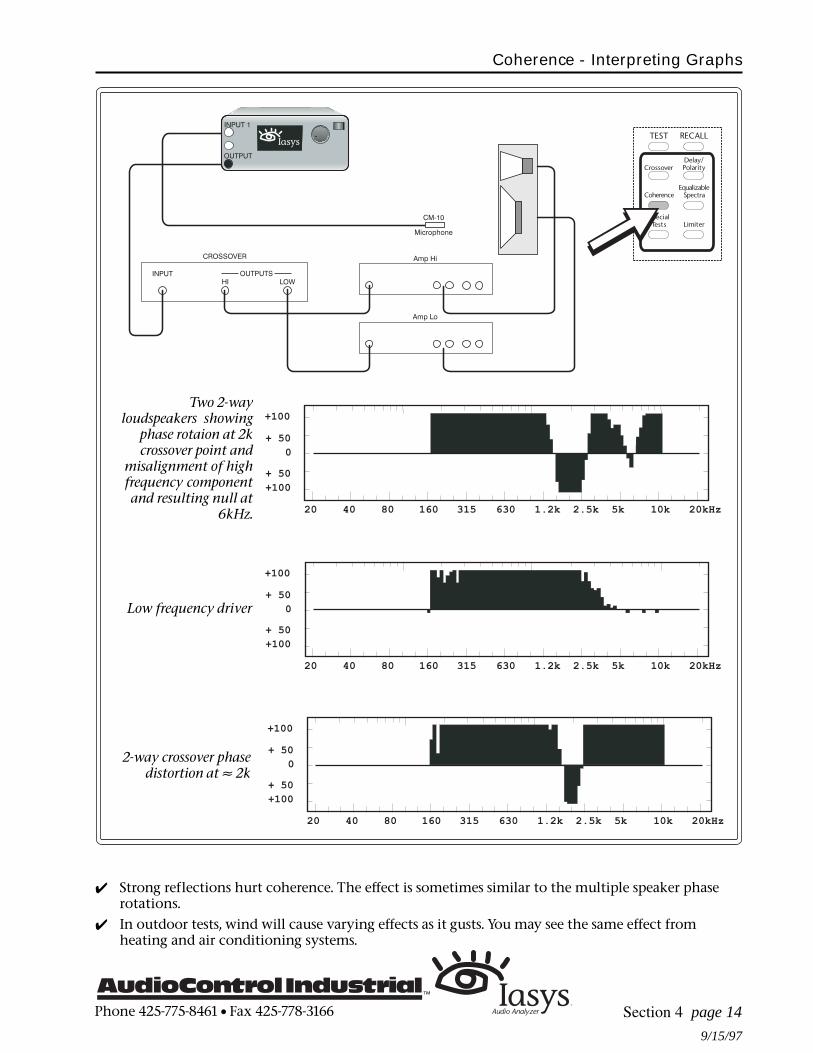
Two 2-way loudspeakers showing phase rotation at 2k crossover point andmisalignment of high frequency component and resulting null at 6kHz.
F

Phone 425-775-8461 • Fax 425-778-3166
9/15/97
Iasys displays a quasi real time graph of phase versus frequency calledcoherence. Interpreting these graphs takes practice and an understanding
of what affects the time arrivals of the signal. Similarly, some situationsmatter more than others with regard to sound quality. The Iasys displayencourages you to make changes, see the results, and learn what is impor-tant to you. The previous section includes information on running the test togenerate coherence graphs.
With the Iasys coherence graph, you see phase versus frequency in a fashionsimilar to the real time spectrum analyzer display of amplitude versusfrequency. Iasys knows the EXACT time the signal should take to arriveback through the microphone. If the signal arrives later or earlier thanexpected it has poorer coherence than a signal arriving in time.
How to Read the Graph• Good coherence, or 100% in correct time, is at the top of the graph.
Signals at the bottom of the graph are in time but out of polarity.• The horizontal center line of the coherence graph is zero coherence. This
means the signal is either not in time or not present.• Each vertical bar on the display is 1/12th of an octave. You may use the
wheel to move the pointer at the top of the screen to pinpoint thefrequency of a vertical bar.
• To make changes and then view the results, press PAUSE. This is veryuseful since the pink noise ceases. A second press of the PAUSE buttonrestarts the tests from the highest frequency. Do not press QUIT since thenyou will have to re-run the Delay test.
Hints on Interpreting Coherence Graphs4 Zero coherence, the horizontal center line, indicates the signal arriving
is not in time with established time of the delay test. Or, it indicates thelack of a signal. The absence of a signal within an established bandwidthis most likely caused by a null. A null comes from multiple signals of thesame frequency canceling each other. At the edges of the bandwidth, thelack of a signal is simply the inability of the loudspeaker to reproducethose frequencies (see diagram).
4 Arrays of multiple speakers are frequently not in the same acousticplane. The results on the coherence graphs may be phase rotations dueto comb filtering as well as nulls of certain frequencies (see diagram). Seeprevious section for hints on array alignment.
4 Speakers typically rotate phase at the lower frequencies of their band-width as the coherence display will show.
4 Crossovers, both passive and active, will show poorer coherence andoften complete phase reversals at the crossover frequency area. A narrowbandwidth coherence reversal from positive to negative is often phasedistortion from a crossover. You can confirm this by comparing thefrequency of the coherence disturbance and frequency of the crossover(see diagram).
Automatic Tests
Coherence - Interpreting Graphs
Section 4 page 13
References:
& Section 4 page 11for runningcoherence tests
Phone 425-775-8461 • Fax 425-778-3166
9/15/97
Coherence - Interpreting Graphs
4 Strong reflections hurt coherence. The effect is sometimes similar to the multiple speaker phaserotations.
4 In outdoor tests, wind will cause varying effects as it gusts. You may see the same effect fromheating and air conditioning systems.
Section 4 page 14
Two 2-wayloudspeakers showing
phase rotaion at 2kcrossover point and
misalignment of highfrequency component
and resulting null at6kHz.
2-way crossover phasedistortion at ≈ 2k
Low frequency driver

Phone 425-775-8461 • Fax 425-778-3166
8/15/98
Iasys displays amplitude versus frequency on a quasi real time basis butwith a unique twist. The amplitude is shown only for those frequencies
which can be controlled by an equalizer. The display is resolution is veryprecise at 1/12 octave. You may toggle back and forth between theEqualizable Spectra graph and the Coherence graph.
Much like a real time spectrum analyzer, you see amplitude versus fre-quency with the Iasys equalizable spectra graph. However, there are somesignificant differences. Iasys only displays those frequencies whose ampli-tude may be changed by an equalizer. That is, the one-twelfth octave displayomits the frequencies that will not have an acoustic output change consis-tent with the electrical signal change of the equalizer.The reasons for equalizer adjustments not effecting acoustical changesinclude frequencies outside the physical limits of the speaker and areas ofpoor coherence including nulls. A null comes from multiple signals of thesame frequency canceling each other and is revealed by the Iasys coherencetest described in the prior pages.If you run the equalizable spectra test after you have adjusted the crossoverfrequency, crossover levels, and delay adjustments for best time alignment,you will find the amplitude graph does not include narrow band peaks ordips and is quite smooth.
To Run an Equalizable Spectra GraphRun a Delay test according to the instruction on pages 5 and 6, sectionfour (this section) immediately prior to running an Equalizable Spectratest. The Equalizable Spectra test (like the Coherence test) will only rundirectly after a Delay test to ensure that the distance to the microphoneis correct.
With the pink noise still on at the end of the Delay test, pressEQUALIZABLE SPECTRA.
To make changes and then view the results, press PAUSE.
A second press of the PAUSE button restarts the tests from the highestfrequency. Do not press QUIT since then you will have to re-run theDelay test.
Turn the wheel to move the pointer at the top of the graph to pinpointthe frequency of a particular area.
Press COHERENCE at any time to see the same data as phase versusfrequency.
Automatic Tests
Equalizable Spectra
Section 4 page 15
References:
& Section 4 page 11for running coherencetests
& Section 6 page 1 onhow to print thestresults

Phone 425-775-8461 • Fax 425-778-3166
8/15/98
How to Recall the Last TestIasys retains the data from the last test run. This is available to you either via the printout or onscreen. To display on screen, select the desired memory bank, push EQUALIZABLE SPECTRA, thenpush EQUALIZABLE SPECTRA a second time. You may toggle between this graph and the Coherencegraph as both are contained in the memory.
How to Read the Graph• Frequencies which are omitted are both not shown as part of the graph and signified by an addi-
tional bar at the top most of the screen. If only one or two 1/12 octave bands are omitted, they canbe hard to see.
• Each step (pixel) in the vertical direction on the graph is one decibel. The entire graph contains arange of approximately 50 decibels.
• If a large portion of the graph is higher or lower than the main graph, you may want to check thecrossover levels again before equalizing.
Equalizable Spectra
Section 4 page 16
Non-equalizable frequencies omitted at low coherence areas

Phone 425-775-8461 • Fax 425-778-3166
8/15/98
Section 5 page 1
Manual Tests
Very sophisticated test tones are part of the automatic tests ofIasys. These test tones are available manually controlled via the but-
tons on the lower right of the Iasys front panel. Here we explore two ofthem— single sine wave tones and pink noise.
Iasys will automatically:• begin this test at a very low signal level• display the SPL at the microphone• display the signal level of the output• for sine waves, begin at the last frequency used, even after the unit is
turned off; and• restart at the same signal level after test is paused
Pink NoiseSounding a lot like hiss, and akin to water torture after long periods of use,pink noise is full bandwidth noise. The pink noise from Iasys is pseudorandom and digitally created sequence repeating approximately every threeseconds.
To use pink noise:Connect the Iasys output to the amplifier powering the driver (or set ofdrivers) you want to test. If testing an electronic component, hook theoutput to the input of the device being tested.
Place the microphone within the listening area and connect to input 1of the Iasys audio analyzer.
For an electronic test, connect the output of the test device to Input 1 ofIasys.
Press the NOISE button on Iasys.
Adjust the test level with the wheel while monitoring on the displayscreen the dBu of the signal output and the SPL of the input to Iasys.
Press PAUSE to mute the test signal and press PAUSE for the second timeto resume at the previous level.
Single Sine Wave TonesConnect the Iasys output to the amplifier powering the driver (or set ofdrivers) you want to test. If testing an electronic component, hook theoutput to the input of the device being tested.
Place the microphone within the listening area and connect to input 1of the Iasys audio analyzer.
For an electronic test, connect the output of the test device to Input 1ofIasys.
Press the SINE button on Iasys.
Adjust the test level with the wheel while monitoring on the displayscreen the dBu of the signal output and the SPL of the input to Iasys.You are in the signal level adjustment mode when the line is under-
neath the dBu value on the middle right of the screen.
Pink Noise and Single Sine Wave Tones

Phone 425-775-8461 • Fax 425-778-3166
8/15/98
Section 5 page 2
Pink Noise and Single Sine Wave Tones
To adjust the frequency, press the FREQUENCY button and then use the wheel only for fine tuning.
For quick jumps to a new frequency, use the OCTAVE SELECT buttons under the display screen. If youare in level setting mode, and press an octave select button, this will put Iasys automatically in thefrequency select mode as noted by the underline beneath the frequency on the display screen.
Press PAUSE to mute the test signal and press PAUSE for the second time to resume at the previouslevel.
Some Useful Information4 Randomness of pink noise; by it’s nature the amplitude of pink noise gyrates. If you are viewing the
output of Iasys on a real time spectrum analyzer (like those from AudioControl Industrial, fineproducts by the way), then select a slow or averaged viewing speed and a dB per step of about 3 dB forbest results.
4 Sine wave purity; due to it’s digital origin, the sine wave created by Iasys is very accurate (± 1 Hz). Thismakes the output of Iasys useful with other test instruments.
4 Speaker stress; a fixed frequency sine wave can be by far the most stressful test of a speaker. You shouldtake extreme care in frequency and, particularly, level and duration when testing a speaker with astatic sine wave.
Noise OUTPUT
-50 dBu
SPL: 54 dB
Sinewave OUTPUT
1.00 kHz -50 dBu
SPL: 58 dB
F

Phone 425-775-8461 • Fax 425-778-3166
8/15/98
Section 5 page 3
Manual Tests
A swept pure tone sine wave can be very useful for finding sympa-thetic vibrations, checking for buzzes and rattles in speaker boxes,
using with an RTA, and many other uses. The swept sine from the Iasys isdoubly useful since you can program the start and stop frequencies as wellas the duration of the sweep.
Iasys will automatically:• begin this test at a very low signal level;• display the SPL at the microphone;• display the signal level of the output;• continue running the sweep until stopped;• begin at the last start, stop and duration settings used, even after the
unit is turned off; and• restart at the same signal level after test is paused.
Programmable Swept Sine Wave TonesThe sweeping sine wave tone of Iasys is continuous. Once the swept tonereaches the upper limit programmed, the tone starts once again from thelower limit automatically. This repeating feature, along with the ability toselect start frequency, stop frequency, and duration, may make this yourfavorite manual test with Iasys.
Connect the Iasys output to the amplifier powering the driver (or set ofdrivers) you want to test. If testing an electronic component, hook theoutput to the input of the device being tested.
Place the microphone within the listening area and connect to input 1of the Iasys audio analyzer.
For an electronic test, connect the output of the test device to Input 1ofIasys.
Press the SWEEP button on Iasys.
Adjust the test level with the wheel while monitoring on the displayscreen the dBu of the signal output and the SPL of the input to Iasys.You are in the signal level adjustment mode when the line is under-neath the dBu value on the middle right of the screen.
To adjust the start and stop frequencies, use the OCTAVE SELECT but-tons under the display screen at any time.
To change the duration of the sweep, press the FREQUENCY button andthen use the wheel while watching the display. The maximum andminimum possible sweep durations depend upon th bandwidth of thesweep selected.
Press PAUSE to mute the test signal and press PAUSE for the second timeto resume at the previous signal level.
Sine Wave Sweeps (Programmable)

Phone 425-775-8461 • Fax 425-778-3166
8/15/98
Sweep Output
40 Hz --2.50kHz
10 sec/swp -10 dBu
SPL: 85 dB
Section 5 page 4
Sine Wave Sweeps (Programmable)
Some Useful Information4 Sweep flatness; due to it’s digital origin, the sweep created by Iasys is extremely flat (± 0.1dB). This
makes the output of Iasys useful with other test instruments.4 Speaker stress; a sweeping sine wave can be a stressful test of a speaker (though not nearly as stress-
ful as a fixed sine wave). You should take particular care with narrow frequencies bands, high levelsand short durations when testing a speaker with a sweep sine wave.
Use octave select buttonsbelow display to selectstart and stop frequencies.

Phone 425-775-8461 • Fax 425-778-3166
9/15/97
Hard copy printout is useful for your own records. The hard copy is alsovaluable to demonstrate to the customer the tests performed, your
expertise in setting up the system, and the baseline in case someone else“improves” the system while you are not there. With Iasys, printing thosetest results only takes the double press of a button.
Iasys will automatically:• print all the information contained within the memory bank selected;• print out the last complete coherence and equalizable spectra sweep;• format the report;• time and date stamp the report and the time of the tests; and• retain the selection of printer type, even after the unit is turned off.
To Print a Test ReportThe format of the test report is pre-programmed in Iasys. All you have to dois connect the printer and load the paper. Iasys takes care of the rest of thework.
Connect the selected printer with an IBM type printer cable to theparallel (DB25) connector on the rear panel of Iasys.
Press RECALL to select the memory bank of test results you wish toprint. After selecting the memory, press QUIT.
Press ENTER to display the “Special Functions” screen.
The print option is automatically highlighted as the top choice.
Press ENTER once more to commence printing
During printing, Iasys will display a message that it is printing
If you wish to print another memory bank of test results, select thatmemory with RECALL and repeat the procedure.
To Change Printer TypePress ENTER to display the “Special Functions” screen.
Select “Setup” by scrolling the arrow with the wheel, to that function.Then press ENTER a second time.
Pick “Printer type” by scrolling the arrow with the wheel. To go to thenext step, press ENTER once more.
Use the wheel to change the setting from “Epson” to “HP Deskjet”,pressing enter when the modification is complete. All cpaital lettersindicate that printer type is selected. The new setting will be main-tained until changed (non-volatile). Note: HP Laserjets (at the time ofthis manual) support HP Deskjet output.
During any step, pressing QUIT aborts the process without changing thepresent settings.
Section 6 page 1
Special Functions
Printing Test Results
References:
& Section 6 page 3 forinformation onchanging time, dateand English/metric
& Section 6 page 5 forhow to erase memo-ries
F
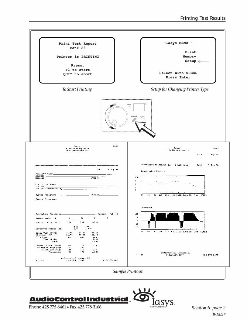
Phone 425-775-8461 • Fax 425-778-3166
9/15/97
Section 6 page 2
Printing Test Results
-Iasys MENU -
PrintMemory
Setup
Select with WHEELPress Enter
ß
Print Test ReportBank 23
Printer is PRINTING
Press:F1 to start
QUIT to abort
Sample Printout
Setup for Changing Printer TypeTo Start Printing

Phone 425-775-8461 • Fax 425-778-3166
8/15/98
Within Iasys is a very precise real time clock which keeps track ofboth the time (to the second) and the date. For distance measure-
ments as part of the delay test, Iasys can display the results in eitherEnglish (feet) or metric (meters).
Iasys will automatically:• maintain time and date after first set;• display both time and date at the bottom of idle screens;• compute distances in either feet or meters; and• preserve all settings until changed.
To Change the Time and DateThe precise clock inside Iasys is not affected by whether the unit is on oroff and plugged in or not. The lifetime of this internal clock is about nineyears. The hours are displayed in 24 hour (military) time and the year 2000is displayed as 00.
Press ENTER to display the “Special Functions” screen.
Select “Setup” by scrolling the arrow with the wheel, to that function.Then press ENTER a second time.
Pick either “Time” or “Date”, again by scrolling the arrow with thewheel. To go to the next step, press ENTER once more.
Now the octave select buttons at the bottom of the screen are function-ing as soft keys to select the function (hour, minute, day, month, or year)to adjust. Use the wheel to change the setting, pressing enter when thealteration is complete.
To Select Metric versus English MeasurementsDistance is the only measurement of Iasys affected by the selection ofEnglish versus Metric. The choice is feet versus meters.
Press ENTER to display the “Special Functions” screen.
Select “Setup” by scrolling the arrow with the wheel, to that function.Then press ENTER a second time.
Pick “English/Metric” by scrolling the arrow with the wheel. To go tothe next step, press ENTER once more.
Use the wheel to change the setting, pressing enter when the modifica-tion is complete. All capital letters indicate the one selected.
During any step, pressing QUIT aborts the process without changing thepresent settings.
Special Functions
Changing Time, Date and Metric versus English
Section 6 page 3
F

Phone 425-775-8461 • Fax 425-778-3166
8/15/98
Changing Time, Date and Metric versus English
Section 6 page 4
-Iasys MENU -
PrintMemory
Setup
Select with WHEELPress Enter
ß
Setup Options
TimeDate
English/Metric
Select with WHEELPress ENTER
ß
Set Time:
Press ENTER when doneor QUIT to abort
13:05HR MIN
Set Date:
Press ENTER when doneor QUIT to abort
23 - JAN - 89| | || | |
Setup Options
TimeDate
English/Metric
Select with WHEELPress ENTER
ß
For Time Change For Date Change
To Set New Time To Set New Date

Phone 425-775-8461 • Fax 425-778-3166
9/15/97
Section 6 page 5
Data is automatically recorded by Iasys at the end of a test andstored in the memory you selected at the beginning of that test. There
are 32 banks of four memories (A,B,C,D) or 128 total. By design, erasingthese memories takes a series of actions much different than normal testing,something you will not do by accident. A single memory, a bank, or a groupof banks all at once may be erased
Iasys will automatically:• record test results in memory at the conclusion of a test;• not change data in a memory if a test is stopped before completion;• maintain data in memories until erased whether the unit is powered or
not; and• always have the same data in memory 33, the example memory.
To Recall MemoriesThe easiest way to recall memories is to use the RECALL button above theautomatic tests buttons. RECALL activates the wheel as shown by the circle(¡) in the upper right corner of the display screen. With the wheel you canscroll through the data stored.If you use RECALL, the data you see depends upon where you were beforepressing the button. In certain circumstances, the recall functions is notavailable. If not available, press QUIT, then RECALL. An alternate way torecall memories is from the Memory management menu accessed bypressing ENTER, the same as the procedure below for erasure.
Memory ConventionsWhen the initial speaker bandwidth characterization test is complete, thatparticular memory will show a diamond (◊) above the letter of thememory. If the delay/polarity test is concluded, either a plus (+) or minus (-)designates the polarity measured. Knowing that the speaker bandwidth testis complete by seeing the diamond above the memory letter not only tellsyou the memory has data but also means you may use that data to runother tests if, and only if, you have not changed the system, venue, ormicrophone position.
Special Functions
Memories Management
To Erase Complete Banks or Group of Banks of MemoriesPress ENTER to display the “Special Functions” screen.
Select “Memory” by scrolling the arrow with the wheel, to that function.Then press ENTER a second time.
Pick “Erase Memory” by scrolling the arrow with the wheel. To go to thenext step, press ENTER once more.
Press F1 for erasing the entire bank. Press F2, F3 or F4 to erase groups of banks
You are then prompted to confirm your decision to erase the entire bank bypressing ENTER.
During any step, pressing QUIT aborts the process without changing thepresent settings.

Phone 425-775-8461 • Fax 425-778-3166
9/15/97
Section 6 page 6
To Erase Only Selected Memories Within A Memory BankYou may want to erase only a single memory within a bank if you wish to re-run a test of a certaindriver, for example, as part of the crossover frequency measuring function. Iasys will not overwrite anexisting bandwidth characterization test memory. You must erase that data.
Press ENTER to display the “Special Functions” screen.
Select “Memory” by scrolling the arrow with the wheel, to that function. Then press ENTER asecond time.
Pick “Erase Memory” by scrolling the arrow with the wheel. To go to the next step, press ENTERonce more.
Press the buttons, now functioning as soft keys, under A, B, C, or D for erasing that selectedmemory.
You are then prompted to confirm your decision to erase the that particular memory by pressingENTER.
Memories Management
-Iasys MENU -
PrintMemory
Setup
Select with WHEELPress Enter
ß
MEMORY
Erase memoryRecall Bank
Select with WHEEL
ß
Erasing Memories
Memory Symbols
-DELAY TEST-Select a Memory
or press DELAY to see test results.Bank: 23◊+◊+◊+◊+◊+ ◊−◊−◊−◊−◊− ◊+◊+◊+◊+◊+ ◊+◊+◊+◊+◊+A B C D
¡
◊ shows bandwidth test run and data present+ or - shows measured and recorded polarity
Press ENTERto erase Bank 19
To erase by groupsF2 for banks 1-10F3 for banks 11-20F4 for banks 21-32
or QUIT to exit.

Phone 425-775-8461 • Fax 425-778-3166
8/15/98
Section 7 page 1
Troubleshooting
Error Messages
While the Iasys does most of its own setup and adjustment, there aresituations either outside of its control or ones in which Iasys wishes
operator confirmation before proceeding. These are the error messages youmay encounter and what they mean.
Gain and Signal Levels Messages
+4 dBu WarningIn all cases, when the output signal level reaches +4 dBu,Iasys asks for operator intervention to continue to raise theamplitude past this point. Pressing F1 continues the test andthe increases the signal output. Alternately, you can quit thetest, adjust the system gains, and resume the test.
<<< WARNING >>><<< WARNING >>><<< WARNING >>><<< WARNING >>><<< WARNING >>>
Output Level isOutput Level isOutput Level isOutput Level isOutput Level is+4 dBu.+4 dBu.+4 dBu.+4 dBu.+4 dBu.
Press:Press:Press:Press:Press: F1 to go higher, F1 to go higher, F1 to go higher, F1 to go higher, F1 to go higher, QUIT to abort. QUIT to abort. QUIT to abort. QUIT to abort. QUIT to abort.
<<< ERROR >>><<< ERROR >>><<< ERROR >>><<< ERROR >>><<< ERROR >>>Pink NoisePink NoisePink NoisePink NoisePink Noise
was not loud enoughwas not loud enoughwas not loud enoughwas not loud enoughwas not loud enoughat max output.at max output.at max output.at max output.at max output.
INCREASE AMPLIFIERINCREASE AMPLIFIERINCREASE AMPLIFIERINCREASE AMPLIFIERINCREASE AMPLIFIERGAIN AND RESTART TESTGAIN AND RESTART TESTGAIN AND RESTART TESTGAIN AND RESTART TESTGAIN AND RESTART TEST
Press QUIT to go backPress QUIT to go backPress QUIT to go backPress QUIT to go backPress QUIT to go back
Noise not Loud Enough, Test StoppedAt +20 dBu, Iasys stops the test and suggests the re-adjustament of the gains in the system. Sometimes themodification should be an increase in the amplifier sensitiv-ity. Often times there is a gain reduction in some intermedi-ate device in the signal chain like a mixer that can be easilycorrected. Iasys will not proceed past +20 dBu signal level.
Delay Test Does Not RunThere are a number of reasons a delay test will not run andeach has a different error message and solution as explainedbelow.Signal strength is too low: since the signal at themicrophone is not as loud as expected, this message prob-ably means an amplifier or other gain has been reducedsince running an earlier bandwidth test.Scatter in received signal: the delay test uses sophisti-
cated noise correlation techniques. Because of this, background noise can be a problem. If you see thiserror message, the acoustical environment is too noisy toaccurately run the test and you need to quiet things downor wait for break time. If the environment is not noisy, trymoving the microphone two to three feet and attempt thetest again.
<<< ERROR >>><<< ERROR >>><<< ERROR >>><<< ERROR >>><<< ERROR >>>Received SignalReceived SignalReceived SignalReceived SignalReceived Signal
strength is too lowstrength is too lowstrength is too lowstrength is too lowstrength is too lowto startto startto startto startto start
the Delay Test.the Delay Test.the Delay Test.the Delay Test.the Delay Test.Increase theIncrease theIncrease theIncrease theIncrease the
Amplifier GainAmplifier GainAmplifier GainAmplifier GainAmplifier Gainand restart the test.and restart the test.and restart the test.and restart the test.and restart the test.
<<< ERROR >>><<< ERROR >>><<< ERROR >>><<< ERROR >>><<< ERROR >>>Too much scatter inToo much scatter inToo much scatter inToo much scatter inToo much scatter inthe received soundthe received soundthe received soundthe received soundthe received sound
to get a goodto get a goodto get a goodto get a goodto get a gooddistance estimate.distance estimate.distance estimate.distance estimate.distance estimate.
Reduce ambient noiseReduce ambient noiseReduce ambient noiseReduce ambient noiseReduce ambient noisethen restartthen restartthen restartthen restartthen restart
the test.the test.the test.the test.the test.

Phone 425-775-8461 • Fax 425-778-3166
8/15/98
Section 7 page 2
Troubleshooting
<<< ERROR >>><<< ERROR >>><<< ERROR >>><<< ERROR >>><<< ERROR >>>Iasys does not hearIasys does not hearIasys does not hearIasys does not hearIasys does not hear
the audio signalthe audio signalthe audio signalthe audio signalthe audio signalit is expecting.it is expecting.it is expecting.it is expecting.it is expecting.
Please check yourPlease check yourPlease check yourPlease check yourPlease check youramplifier and driveramplifier and driveramplifier and driveramplifier and driveramplifier and driver
connections thenconnections thenconnections thenconnections thenconnections thenrestart the test.restart the test.restart the test.restart the test.restart the test.
Not the signal expected: based on knowledge fromprevious tests, Iasys looks for a response at a frequencyconsist with the capabilities of the driver. If you see thismessage, the most likely cause is that you are hooked up to adifferent type loudspeaker than the one tested earlier usingthis memory. For example, if the memory is for a highfrequency horn and the loudspeaker hooked up is 15"woofer, Iasys will detect an inconsistency and ask foroperator intervention.Phase signal strength too low: the delay/distance test
procedure needs a highly coherent signal. That is, a signal with good time alignment at the frequencyof the test. Generally, Iasys knows what frequency to test at for good coherency from the prior testsdetermination of the energy center. The energy center of a single driver is a good phase point. How-ever, the energy center may not be a good phase point if the microphone is in a null or bandwidth testwas on a multi-way, crossovered system (either active orpassive). With a crossovered system, the energy center mayfall at the crossover point. Under these circumstances, to runa delay test override the frequency Iasys selects for this testby using the octave select buttons below the display screen.You want to keep the test frequency close to the energycenter yet outside the phase effect region of the crossover.This region depends upon the slope (among other things) ofthe crossover. If this message occurs with a single dirve, themicrophone may be in a null. Move it two to three feet andtry the test again.
<<< ERROR >>><<< ERROR >>><<< ERROR >>><<< ERROR >>><<< ERROR >>>Phase Signal StrengthPhase Signal StrengthPhase Signal StrengthPhase Signal StrengthPhase Signal Strength
is too low.is too low.is too low.is too low.is too low.Make sure the driverMake sure the driverMake sure the driverMake sure the driverMake sure the driver
is operated at ais operated at ais operated at ais operated at ais operated at ausable Center Freq.usable Center Freq.usable Center Freq.usable Center Freq.usable Center Freq.Press QUIT or DELAYPress QUIT or DELAYPress QUIT or DELAYPress QUIT or DELAYPress QUIT or DELAY
<<< ERROR >>><<< ERROR >>><<< ERROR >>><<< ERROR >>><<< ERROR >>>Iasys cannot readIasys cannot readIasys cannot readIasys cannot readIasys cannot read
the distance to thethe distance to thethe distance to thethe distance to thethe distance to thedriver. Check:driver. Check:driver. Check:driver. Check:driver. Check:
1. Correct driver?1. Correct driver?1. Correct driver?1. Correct driver?1. Correct driver?2. More than one2. More than one2. More than one2. More than one2. More than one driver connected? driver connected? driver connected? driver connected? driver connected?3. Near reflection?3. Near reflection?3. Near reflection?3. Near reflection?3. Near reflection?
Delay Test Runs But Does Not CompleteThis message means that Iasys was not able to satisfactorilycomplete the correlation of noise. In other words, the datawas not of sufficient quality to give an accurate distance.This is another example of the fuzzy logic of Iasys meaningit doesn’t give answers when they do not make sense. Lookfor background noise that became louder during the test,strong reflections, wrong driver connected, or multipledrivers creating interference patterns.

Phone 425-775-8461 • Fax 425-778-3166
8/15/98
Section 7 page 3
Troubleshooting
<<< ERROR >>><<< ERROR >>><<< ERROR >>><<< ERROR >>><<< ERROR >>>“Speaker Level Input”“Speaker Level Input”“Speaker Level Input”“Speaker Level Input”“Speaker Level Input”
signal strengthsignal strengthsignal strengthsignal strengthsignal strengthis too low to startis too low to startis too low to startis too low to startis too low to start
the Limiter Test.the Limiter Test.the Limiter Test.the Limiter Test.the Limiter Test.Increase theIncrease theIncrease theIncrease theIncrease the
Amplifier GainAmplifier GainAmplifier GainAmplifier GainAmplifier Gainand restart the test.and restart the test.and restart the test.and restart the test.and restart the test.
<<< ERROR >>><<< ERROR >>><<< ERROR >>><<< ERROR >>><<< ERROR >>>No signal onNo signal onNo signal onNo signal onNo signal on
“Speaker Level Input”“Speaker Level Input”“Speaker Level Input”“Speaker Level Input”“Speaker Level Input”
check your test setupcheck your test setupcheck your test setupcheck your test setupcheck your test setupconnections, thenconnections, thenconnections, thenconnections, thenconnections, thenrestart the test.restart the test.restart the test.restart the test.restart the test.
SPL/Volts for Mem.SPL/Volts for Mem.SPL/Volts for Mem.SPL/Volts for Mem.SPL/Volts for Mem.at THERMAL LIMIT:at THERMAL LIMIT:at THERMAL LIMIT:at THERMAL LIMIT:at THERMAL LIMIT:
Frequency:Frequency:Frequency:Frequency:Frequency:
SPL=SPL=SPL=SPL=SPL= dB/dB/dB/dB/dB/ VoltsVoltsVoltsVoltsVoltsLine Level:Line Level:Line Level:Line Level:Line Level: dBudBudBudBudBu
SPL/Volts for Mem.SPL/Volts for Mem.SPL/Volts for Mem.SPL/Volts for Mem.SPL/Volts for Mem.RAPID COMPRESSION:RAPID COMPRESSION:RAPID COMPRESSION:RAPID COMPRESSION:RAPID COMPRESSION:
Frequency:Frequency:Frequency:Frequency:Frequency:
SPL=SPL=SPL=SPL=SPL= dB/dB/dB/dB/dB/ VoltsVoltsVoltsVoltsVoltsLine Level:Line Level:Line Level:Line Level:Line Level: dBudBudBudBudBu
SPL/Volts for Mem.SPL/Volts for Mem.SPL/Volts for Mem.SPL/Volts for Mem.SPL/Volts for Mem.AMPLIFIER CLIPPING:AMPLIFIER CLIPPING:AMPLIFIER CLIPPING:AMPLIFIER CLIPPING:AMPLIFIER CLIPPING:
Frequency:Frequency:Frequency:Frequency:Frequency:
SPL=SPL=SPL=SPL=SPL= dB/dB/dB/dB/dB/ VoltsVoltsVoltsVoltsVoltsLine Level:Line Level:Line Level:Line Level:Line Level: dBudBudBudBudBu
Limiter Test CompletionWhen the limiter test is completed, Iasys will tell you whythe test stopped. These are not error message but reasons asto normal completion of the test. There are three conditionsthat stop the test and they are:Thermal limit; this is the thermal/power compressionlimit of the loudspeaker;
Limiter Test Does Not RunLike the delay test, Iasys will inform you as to why it ishaving difficulty starting the limiter test.No Speaker Level Input: Unique to the limiter test,Iasys looks for a speaker level input as well as signal fromthe microphone. It is easy to forget this hookup from theamplifier since it is not necessary for the other tests. Thismessage may also come up if the speaker level connection isfaulty.SignalStrength Too
Low: Based on the level of the Iasys output signal, theanalyzer expects a minimum speaker level power. Since thelimiter test is a test of maximum system capability, theamplifier gains need to be at maximum for this test. If yousee this error message, please check for gain reduction andcorrect it.
Rapid compression; Iasys detected a rapid decrease insignal output (compression) which could be a speaker indistress and about to fail; and
Amplifier clipping; here the speaker limit was notreached as the amplifier limit was reached first.

Phone 425-775-8461 • Fax 425-778-3166
8/15/98
Section 7 page 4
Troubleshooting
Error Messages Related to Signal Connections
Missing microphone/Input signalThis message is pretty much self-explanatory and meansIasys is not measuring an input signal on “Input 1”. Ratherthan continue to increase the signal and possibly damagethe system, Iasys tells you what is wrong. For acousticaltests, this means the mike is not plugged in or some otherconnection in the microphone input signal change is notcomplete. If you are working through a mixer this is an easymistake to make.You may also see this message if there is really low gain on
the signal going into Iasys. This may result if the microphone is being run through a mixer or in adirect electrical test hookup. SIasys is looking for a signal level appropriate for a microphone. If youare using a direct hookup without a mike, increase the gain from the device under test and try the testagain.
No Speaker Level InputFor the limiter test, Iasys looks for a speaker level input as well as signal from the microphone. This isthe only test which uses a speaker level input. For more information on limiter tests error messages, seeabove.
<<< ERROR >>><<< ERROR >>><<< ERROR >>><<< ERROR >>><<< ERROR >>>
No Microphone inputNo Microphone inputNo Microphone inputNo Microphone inputNo Microphone inputon the “Input 1” jack.on the “Input 1” jack.on the “Input 1” jack.on the “Input 1” jack.on the “Input 1” jack.
Check connections,Check connections,Check connections,Check connections,Check connections,then restartthen restartthen restartthen restartthen restart
the Test.the Test.the Test.the Test.the Test.
You must runYou must runYou must runYou must runYou must runa Delay Testa Delay Testa Delay Testa Delay Testa Delay Test
immediately beforeimmediately beforeimmediately beforeimmediately beforeimmediately beforerunning the Coherence Test.running the Coherence Test.running the Coherence Test.running the Coherence Test.running the Coherence Test.
Press DELAY,Press DELAY,Press DELAY,Press DELAY,Press DELAY,or QUIT to exit.or QUIT to exit.or QUIT to exit.or QUIT to exit.or QUIT to exit.
Other Error Messages
Must Run a Delay Test FirstTo run either a Coherence or Equalizable Spectra test, youmust run a delay test immediately prior. Both of these testsrely upon knowing the precise distance from the micro-phone to the speaker since these are time (phase) as well asamplitude results. To insure the accuracy of these tests, Iasysrequires you to run the delay test so that there is no chanceof using a memory for a microphone or speaker type differ-ent than the one presently being tested. For more informa-tion please refer to Section 4, page 11.

Phone 425-775-8461 • Fax 425-778-3166
8/15/98
Specifications
Section 8 page 1
Iasys Specifications
Instrument type Acoustic analyzer for amplitude, phase and frequency, usingfuzzy logic to recommend equipment settings, completely selfcontained and portable
Inputs:Microphone: two balanced low impedance with +12v phantom powering
Connector: 3 pin XLR female
Impedance: Suitable for 150 ohm microphone, actual impedance is 5 Kohms
Amplifier: transformer isolated input
Connector: banana-type jacks
Impedance: 10 Kohms
Signal level: 120 volts rms maximum
Outputs:Type: microprocessor or manually controlled test signals, balanced
Connector: 3 pin XLR male, pin 2 positive
Signal level: -50 dBu to +20 dBu
Display:Type: high energy gas plasma, wide viewing angle
Resolution: 64 x 128 dot matrix, graphic
Memory: real time clock and CMOS memory with battery backup
Filters:Max resolution: 1/48 octave
Bandwidth: software controlled to 1/12 octave
Automatic functions:measure excursion and acceleration related bandwidth;recommend crossover frequency point; show crossover levelsfor easy adjustment; determine thermal compression onset;recommend limiter setting; measure acoustical distance,suggest delay adjustment; verify polarity; show coherence,display equalizable spectra, self-test on power up
Manual functions:Output signals: sine, sweep sine, and pink noise
Sine Wave: accuracy to ±1 Hz, 20 Hz to 20 kHz
Sweep: flatness to ±0.1dB
Pink Noise: total bandwidth ±.5dB, -65 dBu to +20 dBu
RTA: sweping spectrum analyzer, approximately seven secondsweep, one-third octave, auto scaled, 60 to 110 dB SPL
Accessories Included:Microphone: omnidirectional, flat frequency response, back-electret,
condenser type with 15 foot cable (200 foot maximum)
Case: soft carry case with pocket for mike and cables plus shoulderand hand straps
Manual: complete operating manual; online help available from unitfor any function

Phone 425-775-8461 • Fax 425-778-3166
8/15/98
Section 8 page 2
Physical:Dimensions: average large lunch box (4.1" tall x 10" wide x 13.5" deep)
Shipping weight: 9 pounds
Electrical:Power requirements: 100 - 130 VAC 50-60 Hz, 200 - 260 VAC 50 Hz
Power consumption: 30 Watts
Patent Number: 5,555,311
Architect’s and Engineer’s Specifications:The audio analyzer shall be the answer you have been waiting for. The analyzer shall be easy to operate and
not require a Ph.D. to figure out what it is saying. It shall be smaller than a breadbox, yet big enough it does notsprout legs. It shall weigh less than a gallon of milk. The analyzer shall not contribute to the bottomline of largesoftware companies in the Pacific Northwest. It shall not need to be married to a laptop or any other computer.The analyzer shall have thirty-two buttons and an On/Off switch. It shall have a cool feeling wheel that does notscroll through humungous menus. The analyzer’s bright, easy to read screen shall make sense and can be usedoutside a darkroom.
Parallel Interface Signals andPin Assignments.
Iasys
Serial Port Configuration.
This equipment has been tested and found to comply with the following European Standards forElectromagnetic compatibility.
Emission specification EN55013-1
Immunity specification EN55103-2
Low voltage specification EN60065
For continued compliance ensure that all input and output cables are wired with cables shield connected to pin 1of the XLR. The input XLR pin 1 on equipment is generally connected to chassis via a capacitor to prevent groundloops while ensuring good emc compatibility.
The serial output is DTE(Data Terminal/Equipment type)
Pin Signal Name2 RXD Receive Data3 TXD Transmit Data4 DTR Data Terminal Ready5 GND Signal Ground6 DSR Data Set Ready7 RTS Request to Send8 CTS Clear to Send

Phone 425-775-8461 • Fax 425-778-3166
8/15/98
Specifications
Section 9 page 1
People are scared of warranties. Lots of fine print. Months of waitingaround. Well, fear no more. This warranty is designed to make you raveabout us to your friends. It’s a warranty that looks out for you and helpsyou resist the temptation to have your friend, who’s “good with electron-ics”, try to repair your AudioControl Industrial product. So go ahead, readthis warranty, then take a few days to enjoy your new Iasys Audio Ana-lyzer before sending in the warranty card and comments.“Conditional” doesn’t mean anything ominous. The Federal Trade Com-mission tells all manufacturers to use the term to indicate that certainconditions have to be met before they’ll honor the warranty. If you meet allof these conditions, we will warrant all materials and workmanship on theIasys Audio Analyzer for one (1) year from the date you bought it, and wewill fix or replace it, at our option, during that time.Here are the conditional conditions:1. You have to fill out the warranty card and send it to us within 15 days
after purchasing the Iasys Audio Analyzer.2. You must keep your sales receipt for proof of purchase showing when and
from whom the unit was bought. We’re not the only ones who requirethis, so it’s a good habit to get into with any major purchase.
3. The Iasys Audio Analyzer must have originally been purchased froman authorized AudioControl entity. You do not have to be the originalowner, but you do need a copy of the original sales slip.
4. You cannot let anybody who isn’t: (A) the AudioControl factory; or (B)somebody authorized in writing by AudioControl to service the IasysAudio Analyzer. If anyone other than (A), or (B) messes with the IasysAudio Analyzer, that voids your warranty.
5. The warranty is also void if the serial number is altered or removed, or ifthe Iasys Audio Analyzer has been used improperly. Now that soundslike a big loophole, but here is all we mean by it:Unwarranted abuse is: (A) physical damage (don’t use the Iasys AudioAnalyzer to pound nails or beat clients who do not pay their bills); (B)improper connections (120 volts into the XLR jacks can fry the poorthing); (C) sadistic things. This is the best product we know how to build,but if you strap it to the front bumper of your Range Rover, somethingmight break.
Assuming you conform to 1 through 5, and it really isn’t all that hard to do,we get the option of fixing your old unit or replacing it with a new one.
The WARRANTY

Phone 425-775-8461 • Fax 425-778-3166
8/15/98
Section 9 page 2
Legalese SectionThis is the only warranty given by AudioControl Industrial. This warrantygives you specific legal rights, and you may also have rights that vary fromstate to state. Promises of how well the Iasys Audio Analyzer will workare not implied by this warranty. Other than what we’ve said we’ll do inthis warranty, we have no obligation, express or implied. We make nowarranty of merchantability or fitness for any particular purpose. Alsoneither we nor anyone else who has been involved in the development ormanufacture of the unit will have any liability of any incidental, conse-quential, special or punitive damages, including but not limited to any lostprofits or damage to other parts of your system by hooking up to the unit.Whether the claim is one for breach of warranty, negligence of other tort, orany other kind of claim. Some states do not allow limitations of consequen-tial damages.Failure to send in a properly completed warranty card negates any serviceclaims.The warranty included with the unit shall supersede this plain-text version,if there is any inconsistency between the two.
©1998 AudioControl Industrial. All Rights Reserved
Repair service is available at:
Attn: Service Department22410 70th Avenue WestMountlake Terrace, WA 98043 USA(425)775-8461 • FAX (425)778-3166e-mail: [email protected]

Phone 425-775-8461 • Fax 425-778-3166
8/15/98