usg exterior ceiling systems installation guide (english ... · symmetrical carrier spacing and...
TRANSCRIPT
USG Ceiling Solutions
USG Exterior Ceiling Systems
INSTALLATION GUIDE
Cover photo: Computer-generated image © USG Corporation, 2017
The inside front cover is intentionally left blank.
USG EXTERIOR CEILING SYSTEMS INSTALLATION GUIDE
For decades, USG exterior ceiling systems have been utilized in a
wide variety of exterior applications because they not only satisfy
stringent performance requirements and design criteria but also
provide beauty and durability.
These ceiling systems combine traditional modules, elegant linear
pans, or metal panels with a specially engineered suspension system
to create dynamic ceilings featuring clean, contemporary planes.
This installation guide identifies and defines components used in each
system and provides step-by-step instructions used to install each
of the six USG exterior ceiling systems. For additional information,
see the USG Exterior Ceiling Systems Guide, SC2561, which contains
design considerations, test results, and construction details including
seismic applications related to the installation of these systems.
Exterior Ceiling Applications
3 LINEAR METAL CEILING SYSTEMS
Paraline® II
Paraline® Plus
29 METAL PANEL CEILING SYSTEMS
Celebration™ Snap-In
Celebration™ Torsion Spring
55 USG SHEETROCK® BRAND LAY-IN CEILING PANELS
ZXLA™
69 USG DRYWALL SUSPENSION SYSTEM
Ceiling Grid Framing System
For More Information Technical Service
800.USG.4YOU
Website usg.com

Page 2 intentionally left blank.
DESCRIPTION USG Paraline® II Linear Metal Pans combine a unique linear appearance with
the strength and corrosion resistance of aluminum. Paraline II linear metal pans
are supported by testing for a variety of installation requirements for exterior
applications with proper bracing and framing.
This guide outlines the design considerations, test results, and construction
details for the installation of USG Paraline II exterior ceiling systems.
USG exterior assemblies were tested per UL 580, UL 1897, and listed in
PEI Evaluation Report, PER-12055.
NOTES Follow proper safety and industrial hygiene practices while handling and installing all products and systems. Take necessary precautions and wear appropriate personal protective equipment as needed. For product safety information and personal protective equipment recommendations review the safety data sheet. When removing or installing ceiling pans from grid, we recommend wearing a dust mask, cut-resistant gloves, and eye protection. Provide drop cloths to cover and protect furnishings below. When using a ladder or lift, follow the equipment manufacturer’s precautions, instructions, and safety guidelines.
All ceiling products and systems must be installed and maintained in accordance with current USG written instructions and in compliance with ASTM C636, ASTM E580, CISCA, and standard industry practices.
Care must be taken to safeguard products from damage during delivery and while they are stored at the jobsite. The products must always be protected from vibration, chemical fumes, and direct contact with water both before and after installation.
LINEAR METAL CEILING SYSTEMS
Exterior Ceiling Applications
Paraline® II
3 INSTALLATION GUIDE USG Exterior Ceiling Systems Linear Metal Ceiling Systems Paraline II
Components
PARALINE® II
Pans Paraline II linear pans are 12 ft. long aluminum pans with a 3-1/4 in. wide face featuring integral flanges that overlap to form a reveal closure appropriate for exterior soffit applications. They can be perforated or non-perforated. The reveal on the pans can be either matching or black.
Suspension System Symmetrical carriers are 12 ft. aluminum carriers used in exterior applications to hold the Paraline II pans.
Expansion carriers are 4 ft. symmetrical carriers used at the end of standard symmetrical carriers to increase the space between the pans by 1/8 in. to allow for the use of full pans at the perimeter.
Contraction carriers are 4 ft. symmetrical carriers used at the end of standard symmetrical carriers to decrease the space between the pans by 3/32 in. to allow for the use of full pans at the perimeter.
Symmetrical carrier splices are 6 in. splices used at two abutting ends of symmetrical carriers to reinforce the joint.
U-2-3/32 moldings are 12 ft. aluminum wall moldings used at the perimeter of the Paraline II system.
Accessories Hanger reinforcement clips are 2 in. clips used at each hanger wire location.
U-2-3/32 hold-down clips are used at the perimeter to hold the pans flat in the U-molding.
Paraline II splice plates are used to connect two abutting Paraline II pans to reinforce the joint.
90-degree Paraline II splice plates are used to connect two intersecting Paraline II pans to reinforce a 90-degree corner.
Paraline II end plugs are used to finish the ends of Paraline II pans.
Compression post adapters are used with 3/4 in. conduit (by others) to attach the conduit to the symmetrical carriers.
12-gauge hanger wires are a common building product used to suspend acoustical, drywall, and specialty ceilings. They are galvanized for corrosion resistance.
4 INSTALLATION GUIDE USG Exterior Ceiling Systems Linear Metal Ceiling Systems Paraline II
Components
PARALINE® II
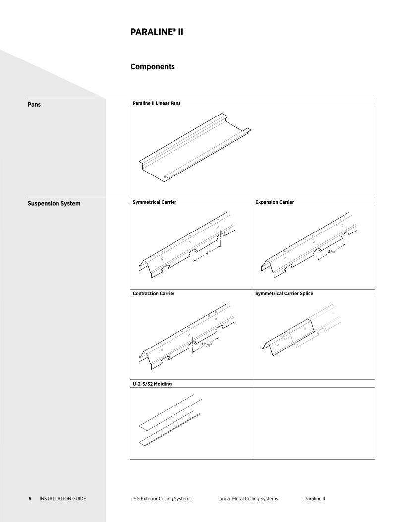
Pans Paraline II Linear Pans
Suspension System Symmetrical Carrier Expansion Carrier
4 " 4 1/8"
Contraction Carrier Symmetrical Carrier Splice
3 15/16"
U-2-3/32 Molding
5 INSTALLATION GUIDE USG Exterior Ceiling Systems Linear Metal Ceiling Systems Paraline II
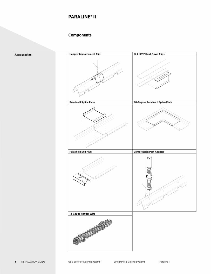
Accessories Hanger Reinforcement Clip U-2-3/32 Hold-Down Clips
Paraline II Splice Plate 90-Degree Paraline II Splice Plate
Paraline II End Plug Compression Post Adapter
12-Gauge Hanger Wire
Components
PARALINE® II
6 INSTALLATION GUIDE USG Exterior Ceiling Systems Linear Metal Ceiling Systems Paraline II
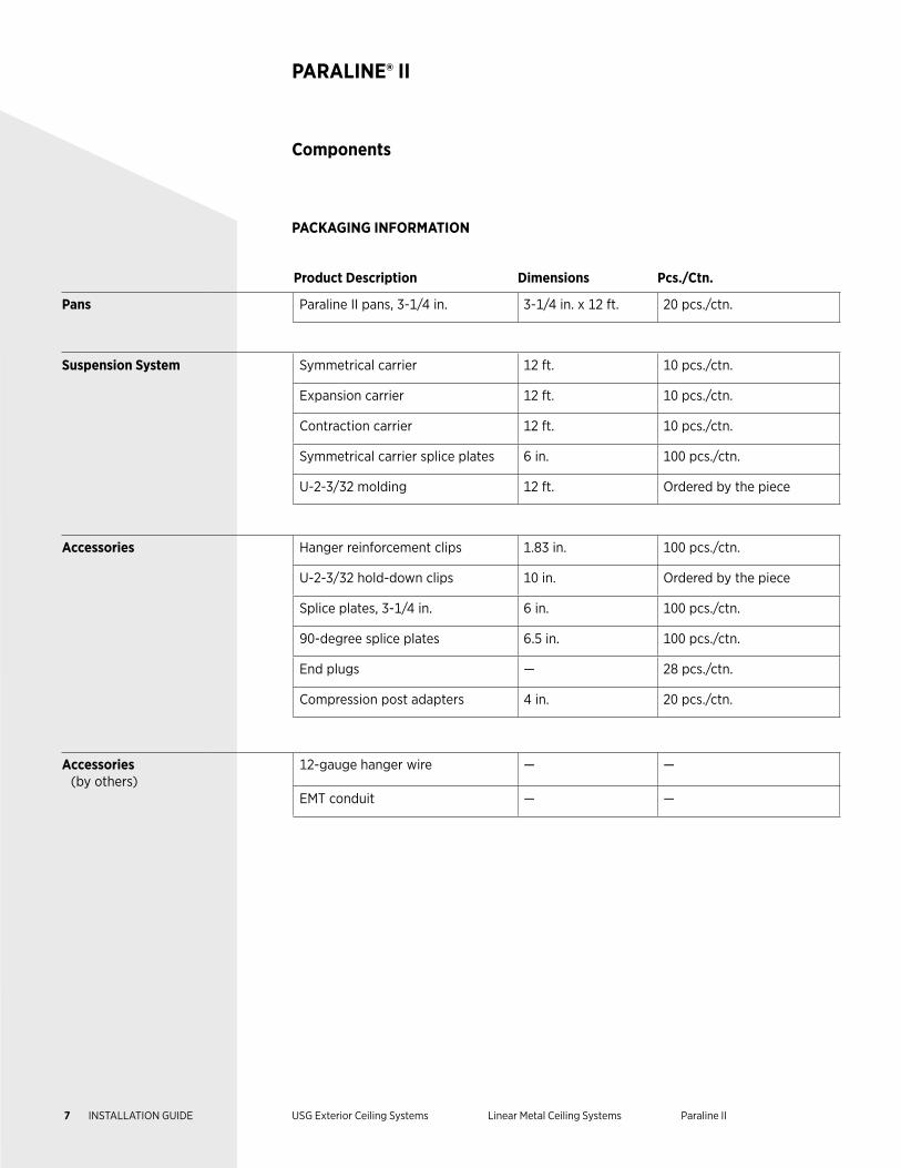
Product Description Dimensions Pcs./Ctn.
Pans Paraline II pans, 3-1/4 in. 3-1/4 in. x 12 ft. 20 pcs./ctn.
Suspension System Symmetrical carrier 12 ft. 10 pcs./ctn.
Expansion carrier 12 ft. 10 pcs./ctn.
Contraction carrier 12 ft. 10 pcs./ctn.
Symmetrical carrier splice plates 6 in. 100 pcs./ctn.
U-2-3/32 molding 12 ft. Ordered by the piece
Accessories Hanger reinforcement clips 1.83 in. 100 pcs./ctn.
U-2-3/32 hold-down clips 10 in. Ordered by the piece
Splice plates, 3-1/4 in. 6 in. 100 pcs./ctn.
90-degree splice plates 6.5 in. 100 pcs./ctn.
End plugs — 28 pcs./ctn.
Compression post adapters 4 in. 20 pcs./ctn.
Accessories (by others)
12-gauge hanger wire — —
EMT conduit — —
Components
PARALINE® II
PACKAGING INFORMATION
7 INSTALLATION GUIDE USG Exterior Ceiling Systems Linear Metal Ceiling Systems Paraline II
Exterior Installation
PARALINE® II
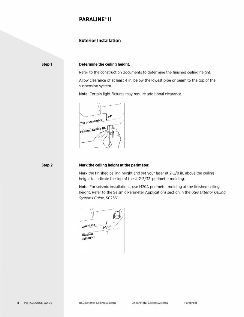
Step 1 Determine the ceiling height.
Refer to the construction documents to determine the finished ceiling height.
Allow clearance of at least 4 in. below the lowest pipe or beam to the top of the suspension system.
Note: Certain light fixtures may require additional clearance.
≥4"
Finished Ceiling Ht.Top of Assembly
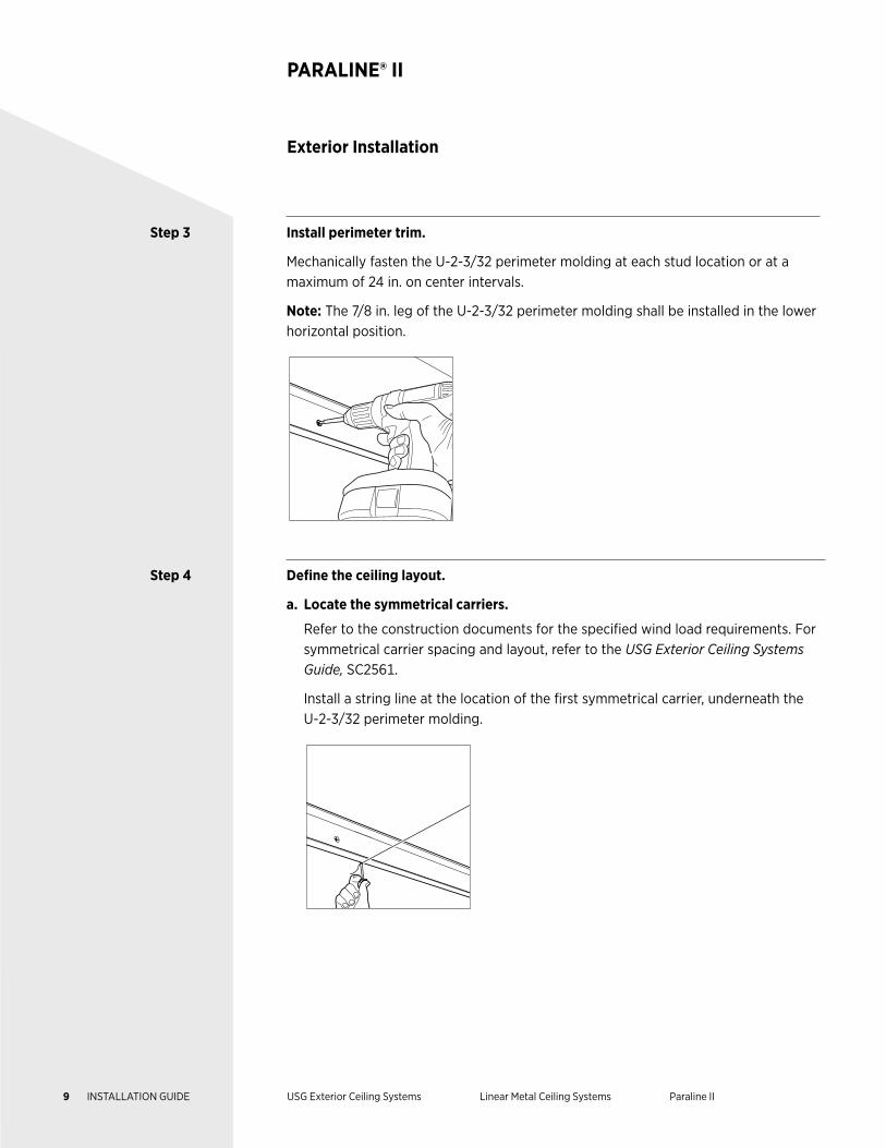
Step 2 Mark the ceiling height at the perimeter.
Mark the finished ceiling height and set your laser at 2-1/8 in. above the ceiling height to indicate the top of the U-2-3/32 perimeter molding.
Note: For seismic installations, use M20A perimeter molding at the finished ceiling height. Refer to the Seismic Perimeter Applications section in the USG Exterior Ceiling Systems Guide, SC2561.
2-1/8"
Finished
Ceiling Ht.
Laser Line
8 INSTALLATION GUIDE USG Exterior Ceiling Systems Linear Metal Ceiling Systems Paraline II
Exterior Installation
PARALINE® II
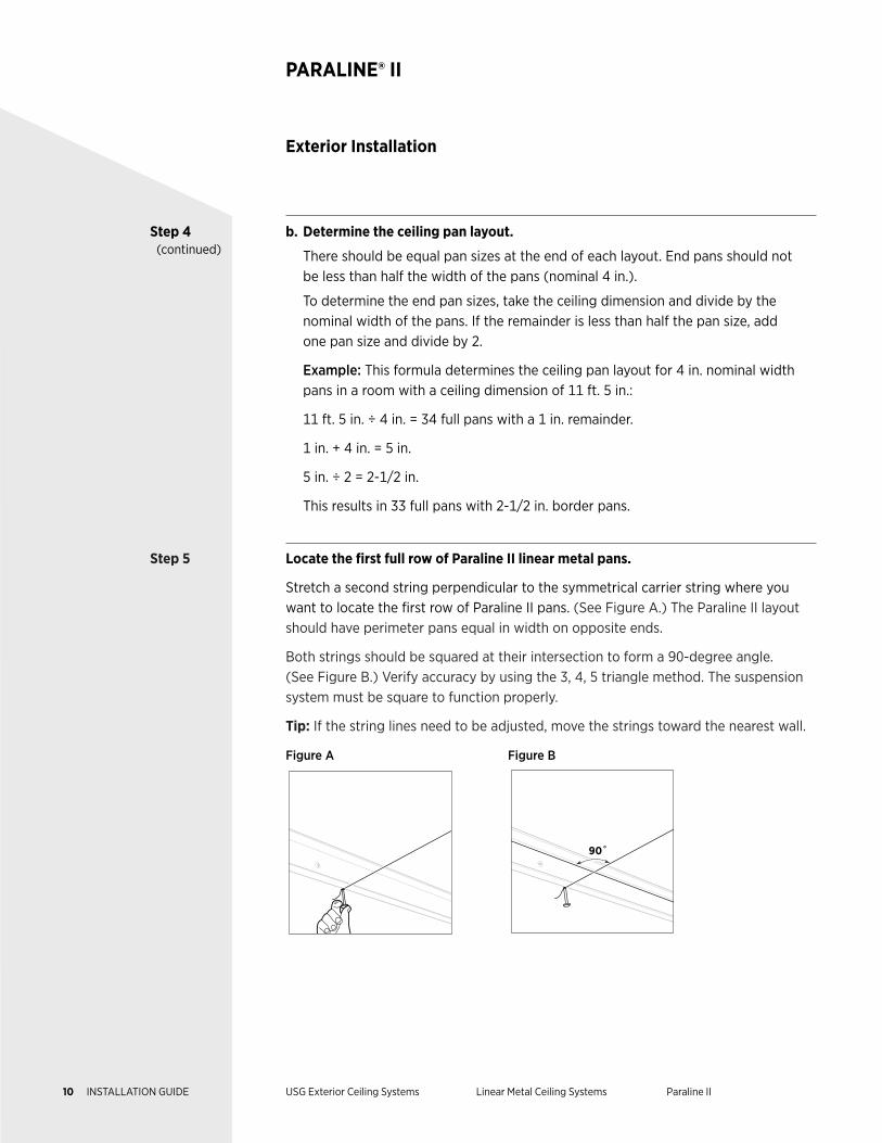
Step 3 Install perimeter trim.
Mechanically fasten the U-2-3/32 perimeter molding at each stud location or at a maximum of 24 in. on center intervals.
Note: The 7/8 in. leg of the U-2-3/32 perimeter molding shall be installed in the lower horizontal position.
Step 4 Define the ceiling layout.
a. Locate the symmetrical carriers.
Refer to the construction documents for the specified wind load requirements. For symmetrical carrier spacing and layout, refer to the USG Exterior Ceiling Systems Guide, SC2561.
Install a string line at the location of the first symmetrical carrier, underneath the U-2-3/32 perimeter molding.
9 INSTALLATION GUIDE USG Exterior Ceiling Systems Linear Metal Ceiling Systems Paraline II
Step 4 (continued)
b. Determine the ceiling pan layout.
There should be equal pan sizes at the end of each layout. End pans should not be less than half the width of the pans (nominal 4 in.).
To determine the end pan sizes, take the ceiling dimension and divide by the nominal width of the pans. If the remainder is less than half the pan size, add one pan size and divide by 2.
Example: This formula determines the ceiling pan layout for 4 in. nominal width pans in a room with a ceiling dimension of 11 ft. 5 in.:
11 ft. 5 in. ÷ 4 in. = 34 full pans with a 1 in. remainder.
1 in. + 4 in. = 5 in.
5 in. ÷ 2 = 2-1/2 in.
This results in 33 full pans with 2-1/2 in. border pans.
Step 5 Locate the first full row of Paraline II linear metal pans.
Stretch a second string perpendicular to the symmetrical carrier string where you want to locate the first row of Paraline II pans. (See Figure A.) The Paraline II layout should have perimeter pans equal in width on opposite ends.
Both strings should be squared at their intersection to form a 90-degree angle. (See Figure B.) Verify accuracy by using the 3, 4, 5 triangle method. The suspension system must be square to function properly.
Tip: If the string lines need to be adjusted, move the strings toward the nearest wall.
Figure A Figure B
90˚
Exterior Installation
PARALINE® II
10 INSTALLATION GUIDE USG Exterior Ceiling Systems Linear Metal Ceiling Systems Paraline II
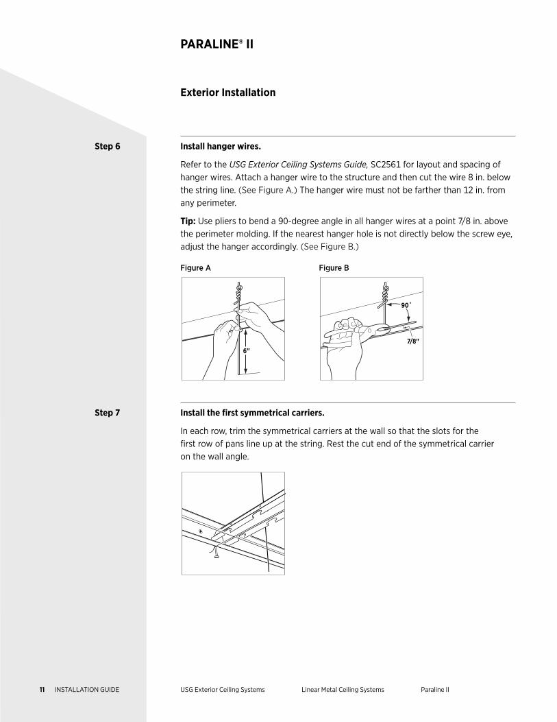
Step 6 Install hanger wires.
Refer to the USG Exterior Ceiling Systems Guide, SC2561 for layout and spacing of hanger wires. Attach a hanger wire to the structure and then cut the wire 8 in. below the string line. (See Figure A.) The hanger wire must not be farther than 12 in. from any perimeter.
Tip: Use pliers to bend a 90-degree angle in all hanger wires at a point 7/8 in. above the perimeter molding. If the nearest hanger hole is not directly below the screw eye, adjust the hanger accordingly. (See Figure B.)
Figure A Figure B
6"
7/8"
90˚
Step 7 Install the first symmetrical carriers.
In each row, trim the symmetrical carriers at the wall so that the slots for the first row of pans line up at the string. Rest the cut end of the symmetrical carrier on the wall angle.
Exterior Installation
PARALINE® II
11 INSTALLATION GUIDE USG Exterior Ceiling Systems Linear Metal Ceiling Systems Paraline II
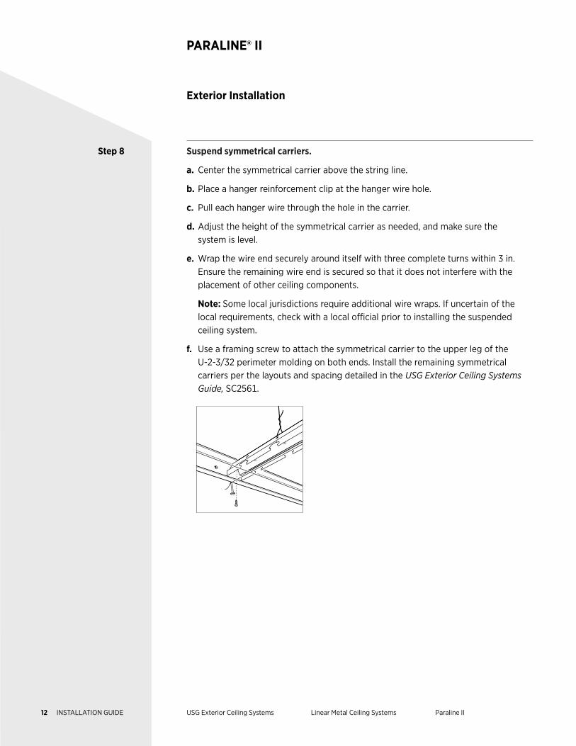
Step 8 Suspend symmetrical carriers.
a. Center the symmetrical carrier above the string line.
b. Place a hanger reinforcement clip at the hanger wire hole.
c. Pull each hanger wire through the hole in the carrier.
d. Adjust the height of the symmetrical carrier as needed, and make sure the system is level.
e. Wrap the wire end securely around itself with three complete turns within 3 in. Ensure the remaining wire end is secured so that it does not interfere with the placement of other ceiling components.
Note: Some local jurisdictions require additional wire wraps. If uncertain of the local requirements, check with a local official prior to installing the suspended ceiling system.
f. Use a framing screw to attach the symmetrical carrier to the upper leg of the U-2-3/32 perimeter molding on both ends. Install the remaining symmetrical carriers per the layouts and spacing detailed in the USG Exterior Ceiling Systems Guide, SC2561.
Exterior Installation
PARALINE® II
12 INSTALLATION GUIDE USG Exterior Ceiling Systems Linear Metal Ceiling Systems Paraline II
Exterior Installation
PARALINE® II
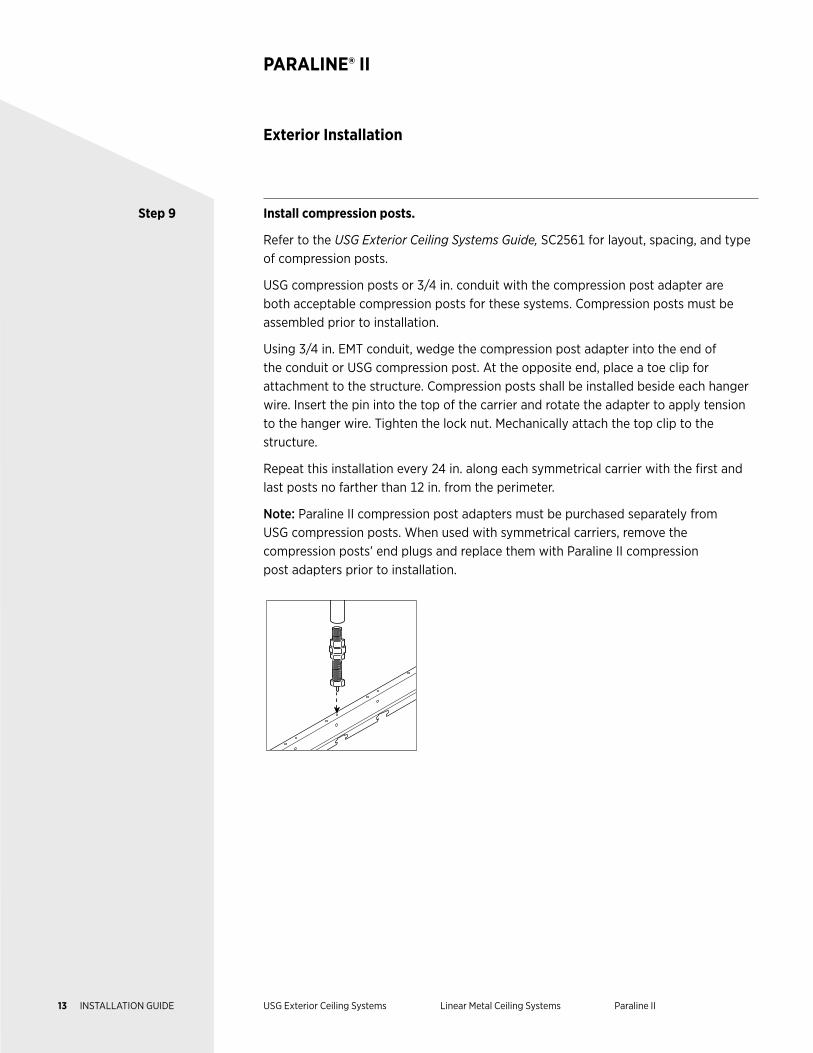
Step 9 Install compression posts.
Refer to the USG Exterior Ceiling Systems Guide, SC2561 for layout, spacing, and type of compression posts.
USG compression posts or 3/4 in. conduit with the compression post adapter are both acceptable compression posts for these systems. Compression posts must be assembled prior to installation.
Using 3/4 in. EMT conduit, wedge the compression post adapter into the end of the conduit or USG compression post. At the opposite end, place a toe clip for attachment to the structure. Compression posts shall be installed beside each hanger wire. Insert the pin into the top of the carrier and rotate the adapter to apply tension to the hanger wire. Tighten the lock nut. Mechanically attach the top clip to the structure.
Repeat this installation every 24 in. along each symmetrical carrier with the first and last posts no farther than 12 in. from the perimeter.
Note: Paraline II compression post adapters must be purchased separately from USG compression posts. When used with symmetrical carriers, remove the compression posts’ end plugs and replace them with Paraline II compression post adapters prior to installation.
13 INSTALLATION GUIDE USG Exterior Ceiling Systems Linear Metal Ceiling Systems Paraline II
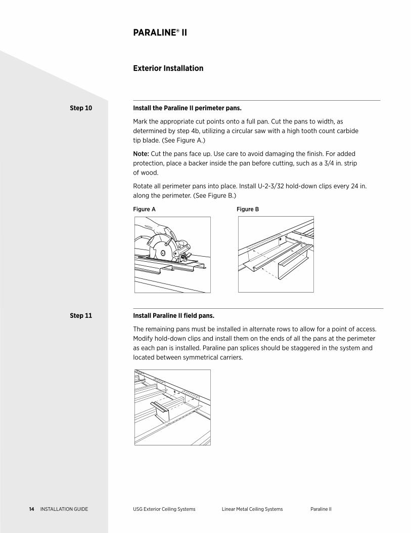
Step 10 Install the Paraline II perimeter pans.
Mark the appropriate cut points onto a full pan. Cut the pans to width, as determined by step 4b, utilizing a circular saw with a high tooth count carbide tip blade. (See Figure A.)
Note: Cut the pans face up. Use care to avoid damaging the finish. For added protection, place a backer inside the pan before cutting, such as a 3/4 in. strip of wood.
Rotate all perimeter pans into place. Install U-2-3/32 hold-down clips every 24 in. along the perimeter. (See Figure B.)
Figure A Figure B
Step 11 Install Paraline II field pans.
The remaining pans must be installed in alternate rows to allow for a point of access. Modify hold-down clips and install them on the ends of all the pans at the perimeter as each pan is installed. Paraline pan splices should be staggered in the system and located between symmetrical carriers.
Exterior Installation
PARALINE® II
14 INSTALLATION GUIDE USG Exterior Ceiling Systems Linear Metal Ceiling Systems Paraline II
DESCRIPTION USG Paraline® Plus Linear Metal Pans combine a unique linear appearance
with the strength and corrosion resistance of aluminum. USG Paraline
Plus linear metal pans are supported by testing for a variety of installation
requirements, including Miami–Dade NOA, for exterior applications with
proper bracing and framing.
This guide outlines the design considerations, test results, and construction
details for the installation of the USG Paraline Plus exterior ceiling system.
USG exterior assemblies were tested per UL 580, UL 1897, TAS 202, and
TAS 203, and listed in PEI Evaluation Report, PER-12055.
NOTES Follow proper safety and industrial hygiene practices while handling and installing all products and systems. Take necessary precautions and wear appropriate personal protective equipment as needed. For product safety information and personal protective equipment recommendations review the safety data sheet. When removing or installing ceiling pans from grid, we recommend wearing a dust mask, cut-resistant gloves, and eye protection. Provide drop cloths to cover and protect furnishings below. When using a ladder or lift, follow the equipment manufacturer’s precautions, instructions, and safety guidelines.
All ceiling products and systems must be installed and maintained in accordance with current USG written instructions and in compliance with ASTM C636, ASTM E580, CISCA, and standard industry practices.
Care must be taken to safeguard products from damage during delivery and while they are stored at the jobsite. The products must always be protected from vibration, chemical fumes, and direct contact with water both before and after installation.
LINEAR METAL CEILING SYSTEMS
Exterior Ceiling Applications
Paraline® Plus
15 INSTALLATION GUIDE USG Exterior Ceiling Systems Linear Metal Ceiling Systems Paraline Plus
Components
PARALINE® PLUS
Pans Paraline Plus 3 in. pans are 3 in. exterior pans that snap onto the Paralock Plus carrier main tee. These pans have a 1 in. depth and are 12 ft. in length.
Paraline Plus 7 in. pans are 7 in. exterior pans that snap onto the Paralock Plus carrier main tee. These pans have a 1 in. depth and are 12 ft. in length.
Paraline Plus 11 in. pans are 11 in. exterior pans that snap onto the Paralock Plus carriermain tee. These pans have a 1 in. depth and are 12 ft. in length.
Suspension System Paralock Plus main tees are the main tees for this system. They can be used for both exterior and interior construction. The standard length is 10 ft.
ZXLA 424 cross tees are zinc-coated exterior 4 ft. cross tees.
ZXLA 224 cross tees are zinc-coated exterior 2 ft. cross tees.
U-2-5/8 channel moldings are aluminum exterior channel moldings with a standard length of 12 ft.
Accessories U-2-5/8 hold-down clips are perimeter hold-down clips with a standard length of 10 in.
Snap-Loc inserts are aluminum, convex recessed or monolithic 1 in. inserts that snap in place between Paraline Plus pans. The standard length is 12 ft.
Paraline Plus 3 in. splice plates are used to connect two abutting Paraline Plus 3 in. pans.
Paraline Plus 7 in. splice plates are used to connect two abutting Paraline Plus 7 in. pans.
Paraline Plus 11 in. splice plates are used to connect two abutting Paraline Plus 11 in. pans.
90-degree Paraline Plus splice plates are used to connect two intersecting Paraline Plus pans to reinforce a 90-degree corner.
Paraline Plus end plugs are used to finish the ends of Paraline Plus pans.
12-gauge hanger wires are a common building product used to suspend acoustical, drywall, and specialty ceilings. They are galvanized for corrosion resistance.
Compression posts are rigid metal supports attached to the Paralock Plus main tees at each hanger wire location and to the building structure. Compression posts prevent upward movement and are required by code.
16 INSTALLATION GUIDE USG Exterior Ceiling Systems Linear Metal Ceiling Systems Paraline Plus
Components
PARALINE® PLUS
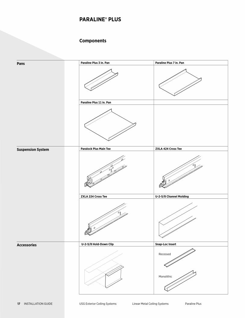
Pans Paraline Plus 3 in. Pan Paraline Plus 7 in. Pan
Paraline Plus 11 in. Pan
Suspension System Paralock Plus Main Tee ZXLA 424 Cross Tee
ZXLA 224 Cross Tee U-2-5/8 Channel Molding
Accessories U-2-5/8 Hold-Down Clip Snap-Loc Insert
Recessed
Monolithic
17 INSTALLATION GUIDE USG Exterior Ceiling Systems Linear Metal Ceiling Systems Paraline Plus
Components
PARALINE® PLUS
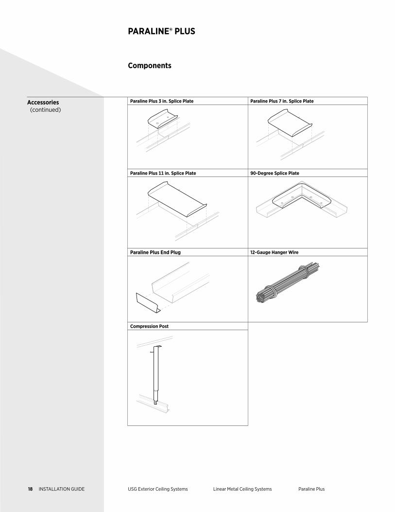
Accessories (continued)
Paraline Plus 3 in. Splice Plate Paraline Plus 7 in. Splice Plate
Paraline Plus 11 in. Splice Plate 90-Degree Splice Plate
Paraline Plus End Plug 12-Gauge Hanger Wire
Compression Post
18 INSTALLATION GUIDE USG Exterior Ceiling Systems Linear Metal Ceiling Systems Paraline Plus
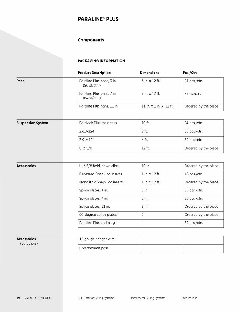
Product Description Dimensions Pcs./Ctn.
Pans Paraline Plus pans, 3 in. (96 sf/ctn.)
3 in. x 12 ft. 24 pcs./ctn.
Paraline Plus pans, 7 in. (64 sf/ctn.)
7 in. x 12 ft. 8 pcs./ctn.
Paraline Plus pans, 11 in. 11 in. x 1 in. x 12 ft. Ordered by the piece
Suspension System Paralock Plus main tees 10 ft. 24 pcs./ctn.
ZXLA224 2 ft. 60 pcs./ctn.
ZXLA424 4 ft. 60 pcs./ctn.
U-2-5/8 12 ft. Ordered by the piece
Accessories U-2-5/8 hold-down clips 10 in. Ordered by the piece
Recessed Snap-Loc inserts 1 in. x 12 ft. 48 pcs./ctn.
Monolithic Snap-Loc inserts 1 in. x 12 ft. Ordered by the piece
Splice plates, 3 in. 6 in. 50 pcs./ctn.
Splice plates, 7 in. 6 in. 50 pcs./ctn.
Splice plates, 11 in. 6 in. Ordered by the piece
90-degree splice plates 9 in. Ordered by the piece
Paraline Plus end plugs — 50 pcs./ctn.
Accessories (by others)
12-gauge hanger wire — —
Compression post — —
Components
PARALINE® PLUS
PACKAGING INFORMATION
19 INSTALLATION GUIDE USG Exterior Ceiling Systems Linear Metal Ceiling Systems Paraline Plus
Exterior Installation
PARALINE® PLUS
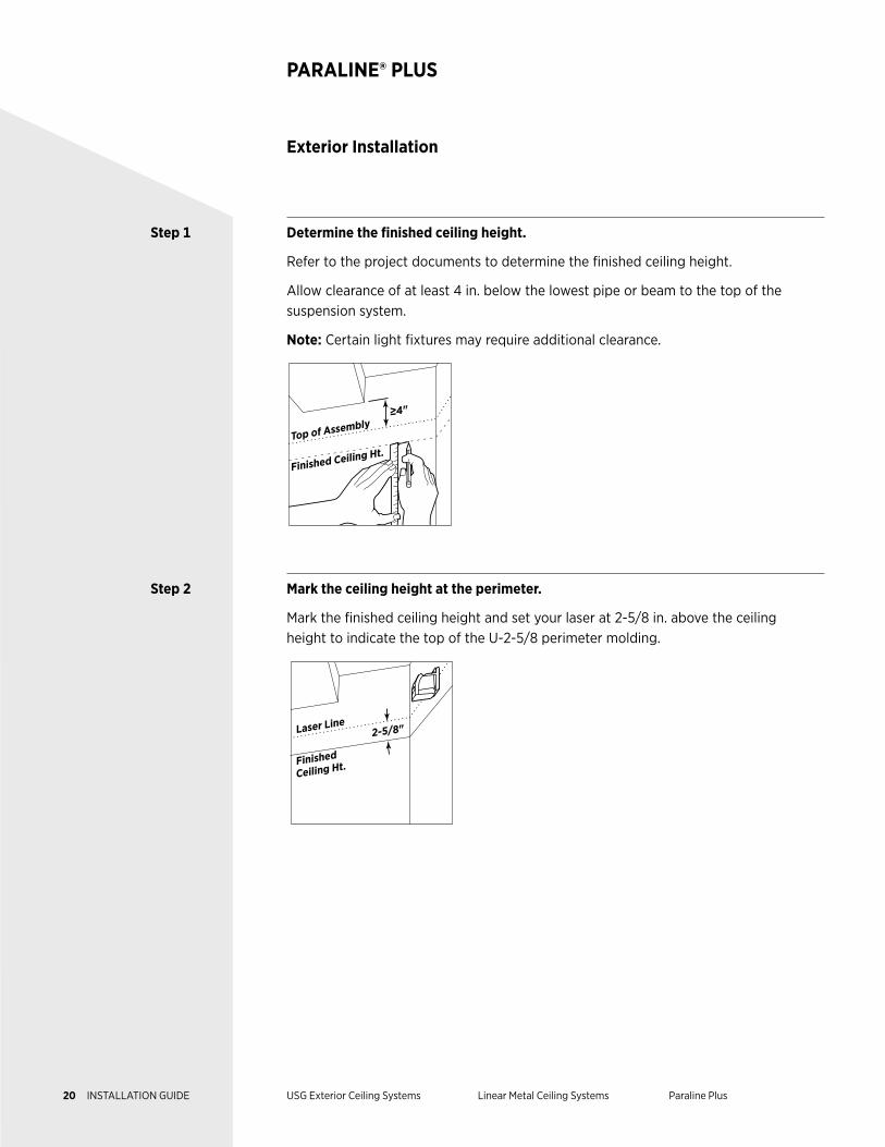
Step 1 Determine the finished ceiling height.
Refer to the project documents to determine the finished ceiling height.
Allow clearance of at least 4 in. below the lowest pipe or beam to the top of the suspension system.
Note: Certain light fixtures may require additional clearance.
≥4"
Finished Ceiling Ht.Top of Assembly
Step 2 Mark the ceiling height at the perimeter.
Mark the finished ceiling height and set your laser at 2-5/8 in. above the ceiling height to indicate the top of the U-2-5/8 perimeter molding.
2-5/8"
Finished
Ceiling Ht.
Laser Line
20 INSTALLATION GUIDE USG Exterior Ceiling Systems Linear Metal Ceiling Systems Paraline Plus
Exterior Installation
PARALINE® PLUS
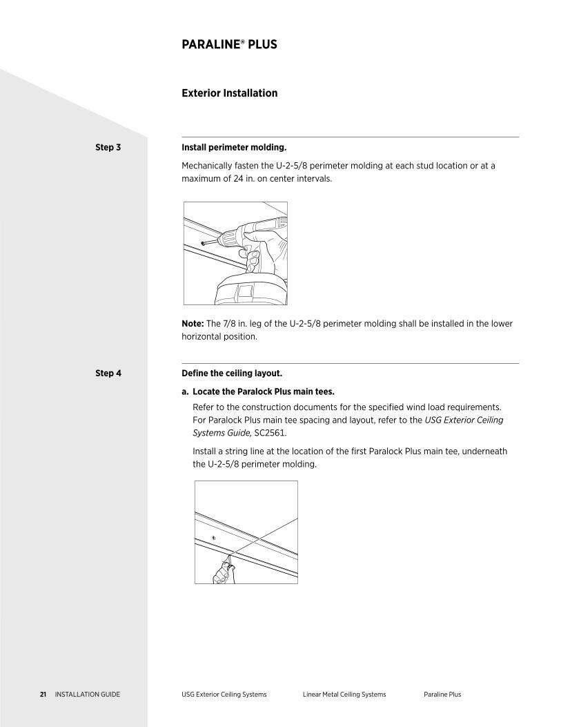
Step 3 Install perimeter molding.
Mechanically fasten the U-2-5/8 perimeter molding at each stud location or at a maximum of 24 in. on center intervals.
Note: The 7/8 in. leg of the U-2-5/8 perimeter molding shall be installed in the lower horizontal position.
Step 4 Define the ceiling layout.
a. Locate the Paralock Plus main tees.
Refer to the construction documents for the specified wind load requirements. For Paralock Plus main tee spacing and layout, refer to the USG Exterior Ceiling Systems Guide, SC2561.
Install a string line at the location of the first Paralock Plus main tee, underneath the U-2-5/8 perimeter molding.
21 INSTALLATION GUIDE USG Exterior Ceiling Systems Linear Metal Ceiling Systems Paraline Plus
Step 4 (continued)
b. Determine the ceiling pan layout.
There should be equal pan sizes at the end of each layout. The end pan should not be less than half the width of the pan (nominal 4 in., 8 in., and 12 in.).
To determine the end pan sizes, take the ceiling dimension and divide by the nominal width of the pans. If the remainder is less than half the pan size, add one pan size and divide by 2.
Example: This formula determines the ceiling pan layout for 4 in. nominal width pans in a room with a ceiling dimension of 11 ft. 5 in.:
11 ft. 5 in. ÷ 4 in. = 34 full pans with a 1 in. remainder.
1 in. + 4 in. = 5 in.
5 in. ÷ 2 = 2-1/2 in.
This results in 33 full pans with 2-1/2 in. border pans.
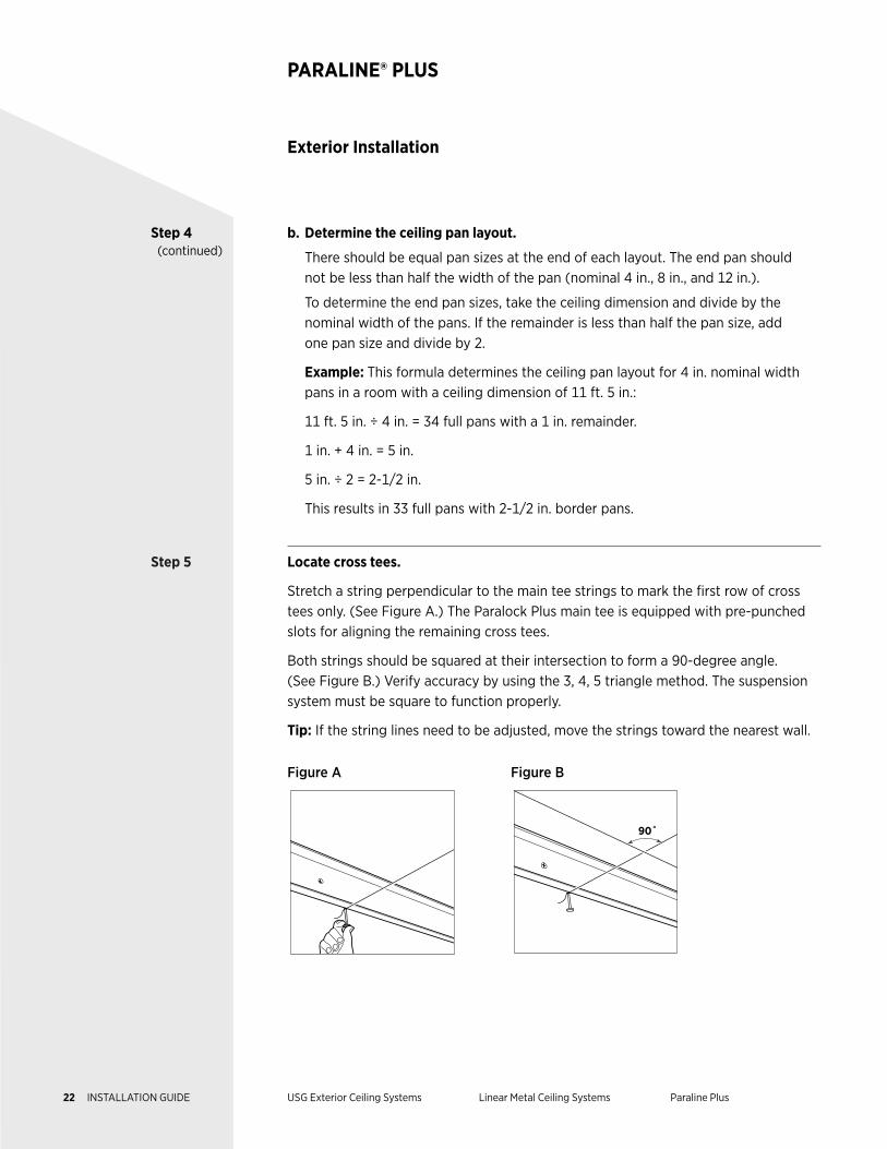
Step 5 Locate cross tees.
Stretch a string perpendicular to the main tee strings to mark the first row of cross tees only. (See Figure A.) The Paralock Plus main tee is equipped with pre-punched slots for aligning the remaining cross tees.
Both strings should be squared at their intersection to form a 90-degree angle. (See Figure B.) Verify accuracy by using the 3, 4, 5 triangle method. The suspension system must be square to function properly.
Tip: If the string lines need to be adjusted, move the strings toward the nearest wall.
Figure A Figure B
90˚
Exterior Installation
PARALINE® PLUS
22 INSTALLATION GUIDE USG Exterior Ceiling Systems Linear Metal Ceiling Systems Paraline Plus
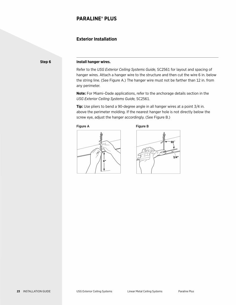
Step 6 Install hanger wires.
Refer to the USG Exterior Ceiling Systems Guide, SC2561 for layout and spacing of hanger wires. Attach a hanger wire to the structure and then cut the wire 6 in. below the string line. (See Figure A.) The hanger wire must not be farther than 12 in. from any perimeter.
Note: For Miami–Dade applications, refer to the anchorage details section in the USG Exterior Ceiling Systems Guide, SC2561.
Tip: Use pliers to bend a 90-degree angle in all hanger wires at a point 3/4 in. above the perimeter molding. If the nearest hanger hole is not directly below the screw eye, adjust the hanger accordingly. (See Figure B.)
Figure A Figure B
6"
3/4"
90˚
Exterior Installation
PARALINE® PLUS
23 INSTALLATION GUIDE USG Exterior Ceiling Systems Linear Metal Ceiling Systems Paraline Plus
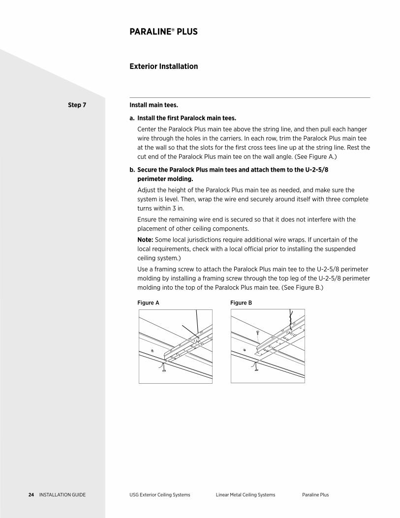
Step 7 Install main tees.
a. Install the first Paralock main tees.
Center the Paralock Plus main tee above the string line, and then pull each hanger wire through the holes in the carriers. In each row, trim the Paralock Plus main tee at the wall so that the slots for the first cross tees line up at the string line. Rest the cut end of the Paralock Plus main tee on the wall angle. (See Figure A.)
b. Secure the Paralock Plus main tees and attach them to the U-2-5/8 perimeter molding.
Adjust the height of the Paralock Plus main tee as needed, and make sure the system is level. Then, wrap the wire end securely around itself with three complete turns within 3 in.
Ensure the remaining wire end is secured so that it does not interfere with the placement of other ceiling components.
Note: Some local jurisdictions require additional wire wraps. If uncertain of the local requirements, check with a local official prior to installing the suspended ceiling system.)
Use a framing screw to attach the Paralock Plus main tee to the U-2-5/8 perimeter molding by installing a framing screw through the top leg of the U-2-5/8 perimeter molding into the top of the Paralock Plus main tee. (See Figure B.)
Figure A Figure B
Exterior Installation
PARALINE® PLUS
24 INSTALLATION GUIDE USG Exterior Ceiling Systems Linear Metal Ceiling Systems Paraline Plus
Exterior Installation
PARALINE® PLUS
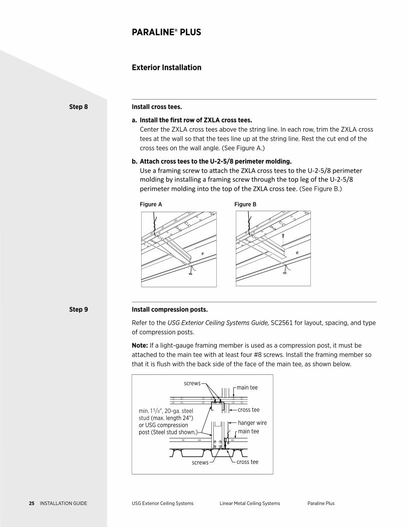
Step 8 Install cross tees.
a. Install the first row of ZXLA cross tees. Center the ZXLA cross tees above the string line. In each row, trim the ZXLA cross
tees at the wall so that the tees line up at the string line. Rest the cut end of the cross tees on the wall angle. (See Figure A.)
b. Attach cross tees to the U-2-5/8 perimeter molding. Use a framing screw to attach the ZXLA cross tees to the U-2-5/8 perimeter
molding by installing a framing screw through the top leg of the U-2-5/8 perimeter molding into the top of the ZXLA cross tee. (See Figure B.)
Figure A Figure B
Step 9 Install compression posts.
Refer to the USG Exterior Ceiling Systems Guide, SC2561 for layout, spacing, and type of compression posts.
Note: If a light-gauge framing member is used as a compression post, it must be attached to the main tee with at least four #8 screws. Install the framing member so that it is flush with the back side of the face of the main tee, as shown below.
screws
screws
cross tee
cross tee
hanger wire
min. 1 5/8", 20-ga. steel stud (max. length 24") or USG compression post (Steel stud shown.) main tee
main tee
25 INSTALLATION GUIDE USG Exterior Ceiling Systems Linear Metal Ceiling Systems Paraline Plus
Exterior Installation
PARALINE® PLUS
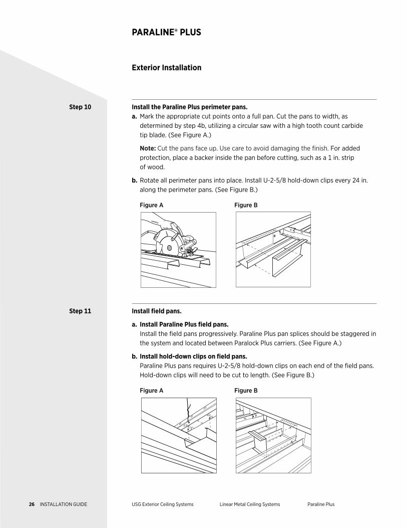
Step 10 Install the Paraline Plus perimeter pans. a. Mark the appropriate cut points onto a full pan. Cut the pans to width, as
determined by step 4b, utilizing a circular saw with a high tooth count carbide tip blade. (See Figure A.)
Note: Cut the pans face up. Use care to avoid damaging the finish. For added protection, place a backer inside the pan before cutting, such as a 1 in. strip of wood.
b. Rotate all perimeter pans into place. Install U-2-5/8 hold-down clips every 24 in. along the perimeter pans. (See Figure B.)
Figure A Figure B
Step 11 Install field pans.
a. Install Paraline Plus field pans. Install the field pans progressively. Paraline Plus pan splices should be staggered in
the system and located between Paralock Plus carriers. (See Figure A.)
b. Install hold-down clips on field pans. Paraline Plus pans requires U-2-5/8 hold-down clips on each end of the field pans.
Hold-down clips will need to be cut to length. (See Figure B.)
Figure A Figure B
26 INSTALLATION GUIDE USG Exterior Ceiling Systems Linear Metal Ceiling Systems Paraline Plus
Exterior Installation
PARALINE® PLUS
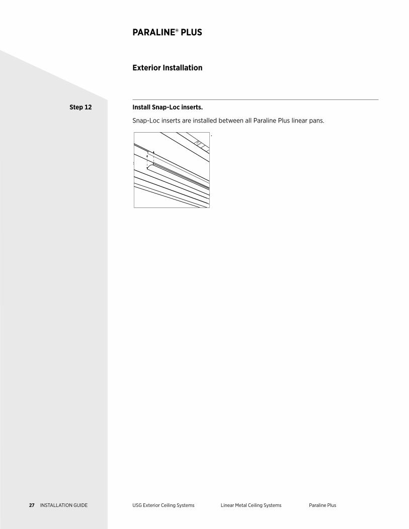
Step 12 Install Snap-Loc inserts.
Snap-Loc inserts are installed between all Paraline Plus linear pans.
.
27 INSTALLATION GUIDE USG Exterior Ceiling Systems Linear Metal Ceiling Systems Paraline Plus

Page 28 is intentionally left blank.
DESCRIPTION USG Celebration™ Snap-In Metal Panels combine a unique, monolithic
appearance with the hidden strength and corrosion resistance of aluminum.
Celebration Snap-In metal panels are supported by testing for a variety of
installation requirements, including Miami–Dade NOA, for exterior applications
with proper bracing and framing.
This guide outlines the design considerations, test results, and construction
details for the installation of the USG Celebration Snap-In metal panels
exterior ceiling system. USG exterior assemblies were tested per UL 580,
UL 1897, TAS 202, and TAS 203, and listed in PEI Evaluation Report, PER-
12055.
NOTES Follow proper safety and industrial hygiene practices while handling and installing all products and systems. Take necessary precautions and wear appropriate personal protective equipment as needed. For product safety information and personal protective equipment recommendations review the safety data sheet. When removing or installing ceiling panels from grid, we recommend wearing a dust mask, cut-resistant gloves, and eye protection. Provide drop cloths to cover and protect furnishings below. When using a ladder or lift, follow the equipment manufacturer’s precautions, instructions, and safety guidelines.
All ceiling products and systems must be installed and maintained in accordance with current USG written instructions and in compliance with ASTM C636, ASTM E580, CISCA, and standard industry practices.
Care must be taken to safeguard products from damage during delivery and while they are stored at the jobsite. The products must always be protected from vibration, chemical fumes, and direct contact with water both before and after installation.
METAL PANEL CEILING SYSTEMS
Exterior Ceiling Applications
Celebration™ Snap-In
29 INSTALLATION GUIDE USG Exterior Ceiling Systems Metal Panel Ceiling Systems Celebration Snap-In
Components
CELEBRATION™ SNAP-IN
Panels Field panels are located in the field of the ceiling, not on the perimeter.
Perimeter panels are located on the edge or perimeter of the room. They may need to be cut.
Suspension System DXFEV main tees are slotted grid systems with G90 galvanization and a standard length of 12 ft.
DXFEV 4 ft. cross tees are slotted grid systems with G90 galvanization.
DXFEV 2 ft. cross tees are slotted grid systems with G90 galvanization.
U-2-3/32 channel moldings are aluminum exterior channel molds with a standard length of 12 ft.
Accessories U-2-3/32 hold-down clips are perimeter clips with a standard length of 10 in.
Arrowhead reveal spacers come in 25 ft. and 100 ft. rolls and are installed adjacent to cut perimeter panels or when field panels are installed adjacent to light fixtures.
Round reveal spacers come in 100 ft. rolls and are installed adjacent to air diffusers or light fixtures.
12-gauge hanger wires are a common building product used to suspend acoustical, drywall, and specialty ceilings. They are galvanized for corrosion resistance.
Compression posts are rigid metal supports attached to the main tees, at each hanger wire location, and to the building structure. Compression posts prevent upward movement and are required by code.
30 INSTALLATION GUIDE USG Exterior Ceiling Systems Metal Panel Ceiling Systems Celebration Snap-In
Components
CELEBRATION™ SNAP-IN
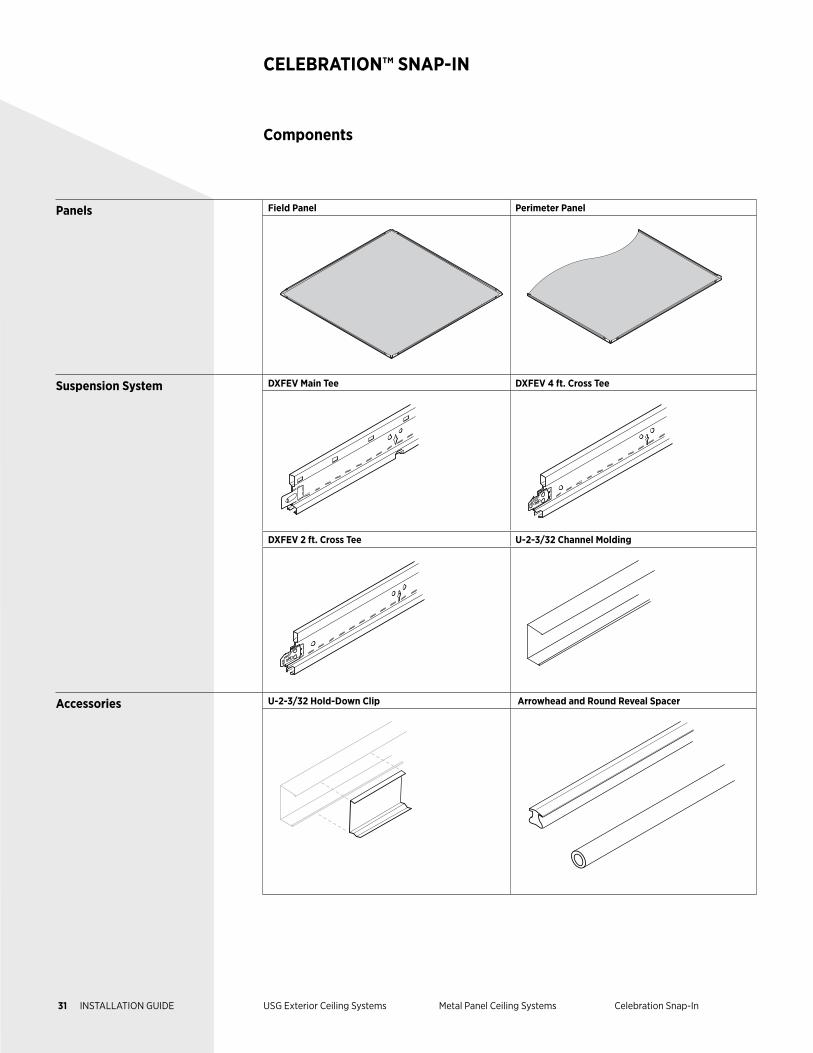
Panels Field Panel Perimeter Panel
Suspension System DXFEV Main Tee DXFEV 4 ft. Cross Tee
DXFEV 2 ft. Cross Tee U-2-3/32 Channel Molding
Accessories U-2-3/32 Hold-Down Clip Arrowhead and Round Reveal Spacer
31 INSTALLATION GUIDE USG Exterior Ceiling Systems Metal Panel Ceiling Systems Celebration Snap-In
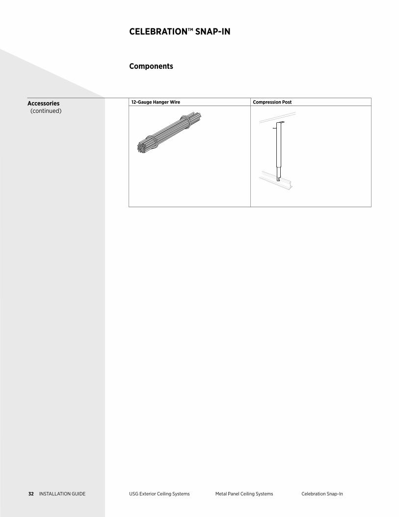
Accessories (continued)
12-Gauge Hanger Wire Compression Post
Components
CELEBRATION™ SNAP-IN
32 INSTALLATION GUIDE USG Exterior Ceiling Systems Metal Panel Ceiling Systems Celebration Snap-In
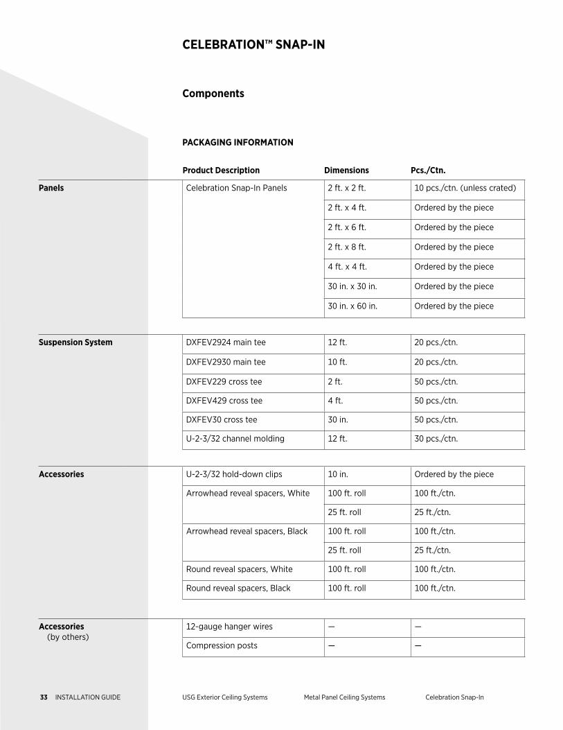
Product Description Dimensions Pcs./Ctn.
Panels Celebration Snap-In Panels 2 ft. x 2 ft. 10 pcs./ctn. (unless crated)
2 ft. x 4 ft. Ordered by the piece
2 ft. x 6 ft. Ordered by the piece
2 ft. x 8 ft. Ordered by the piece
4 ft. x 4 ft. Ordered by the piece
30 in. x 30 in. Ordered by the piece
30 in. x 60 in. Ordered by the piece
Suspension System DXFEV2924 main tee 12 ft. 20 pcs./ctn.
DXFEV2930 main tee 10 ft. 20 pcs./ctn.
DXFEV229 cross tee 2 ft. 50 pcs./ctn.
DXFEV429 cross tee 4 ft. 50 pcs./ctn.
DXFEV30 cross tee 30 in. 50 pcs./ctn.
U-2-3/32 channel molding 12 ft. 30 pcs./ctn.
Accessories U-2-3/32 hold-down clips 10 in. Ordered by the piece
Arrowhead reveal spacers, White 100 ft. roll 100 ft./ctn.
25 ft. roll 25 ft./ctn.
Arrowhead reveal spacers, Black 100 ft. roll 100 ft./ctn.
25 ft. roll 25 ft./ctn.
Round reveal spacers, White 100 ft. roll 100 ft./ctn.
Round reveal spacers, Black 100 ft. roll 100 ft./ctn.
Accessories (by others)
12-gauge hanger wires — —
Compression posts — —
Components
CELEBRATION™ SNAP-IN
PACKAGING INFORMATION
33 INSTALLATION GUIDE USG Exterior Ceiling Systems Metal Panel Ceiling Systems Celebration Snap-In
Exterior Installation
CELEBRATION™ SNAP-IN
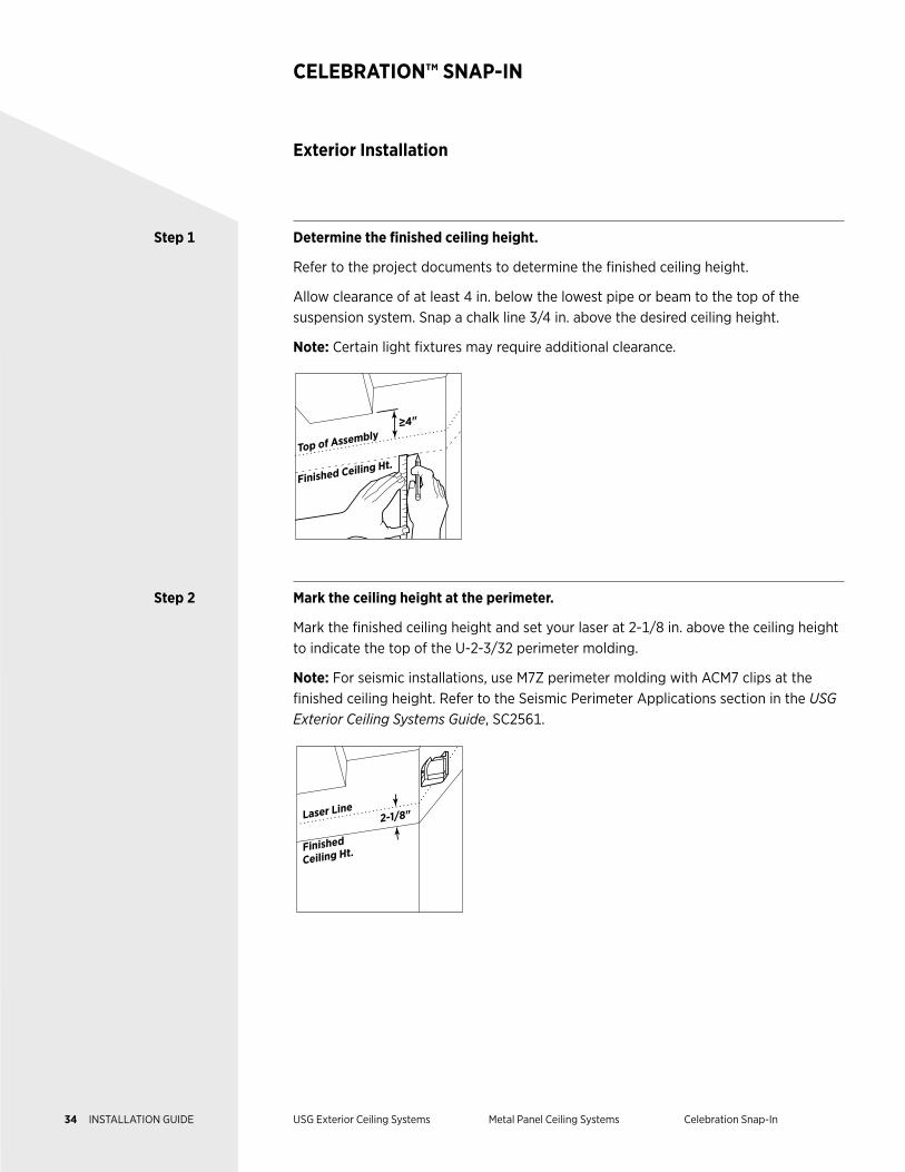
Step 1 Determine the finished ceiling height.
Refer to the project documents to determine the finished ceiling height.
Allow clearance of at least 4 in. below the lowest pipe or beam to the top of the suspension system. Snap a chalk line 3/4 in. above the desired ceiling height.
Note: Certain light fixtures may require additional clearance.
≥4"
Finished Ceiling Ht.Top of Assembly
Step 2 Mark the ceiling height at the perimeter.
Mark the finished ceiling height and set your laser at 2-1/8 in. above the ceiling height to indicate the top of the U-2-3/32 perimeter molding.
Note: For seismic installations, use M7Z perimeter molding with ACM7 clips at the finished ceiling height. Refer to the Seismic Perimeter Applications section in the USG Exterior Ceiling Systems Guide, SC2561.
2-1/8"
Finished
Ceiling Ht.
Laser Line
34 INSTALLATION GUIDE USG Exterior Ceiling Systems Metal Panel Ceiling Systems Celebration Snap-In
Exterior Installation
CELEBRATION™ SNAP-IN
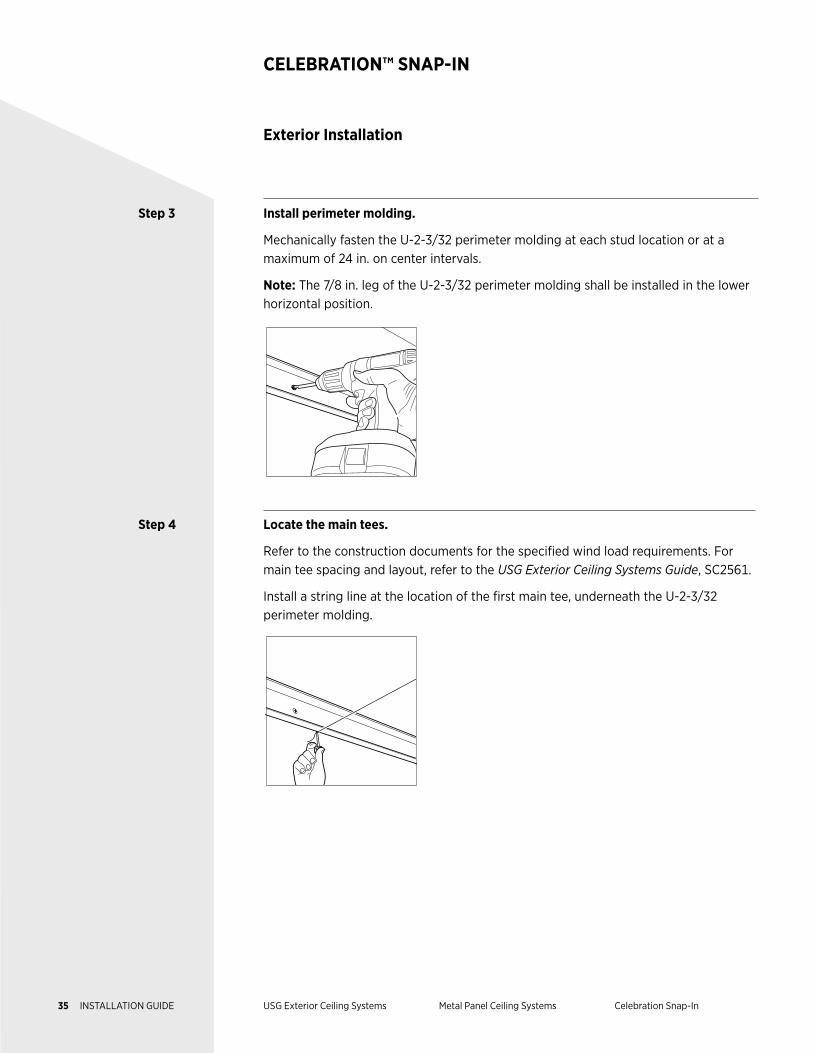
Step 3 Install perimeter molding.
Mechanically fasten the U-2-3/32 perimeter molding at each stud location or at a maximum of 24 in. on center intervals.
Note: The 7/8 in. leg of the U-2-3/32 perimeter molding shall be installed in the lower horizontal position.
Step 4 Locate the main tees.
Refer to the construction documents for the specified wind load requirements. For main tee spacing and layout, refer to the USG Exterior Ceiling Systems Guide, SC2561.
Install a string line at the location of the first main tee, underneath the U-2-3/32 perimeter molding.
35 INSTALLATION GUIDE USG Exterior Ceiling Systems Metal Panel Ceiling Systems Celebration Snap-In
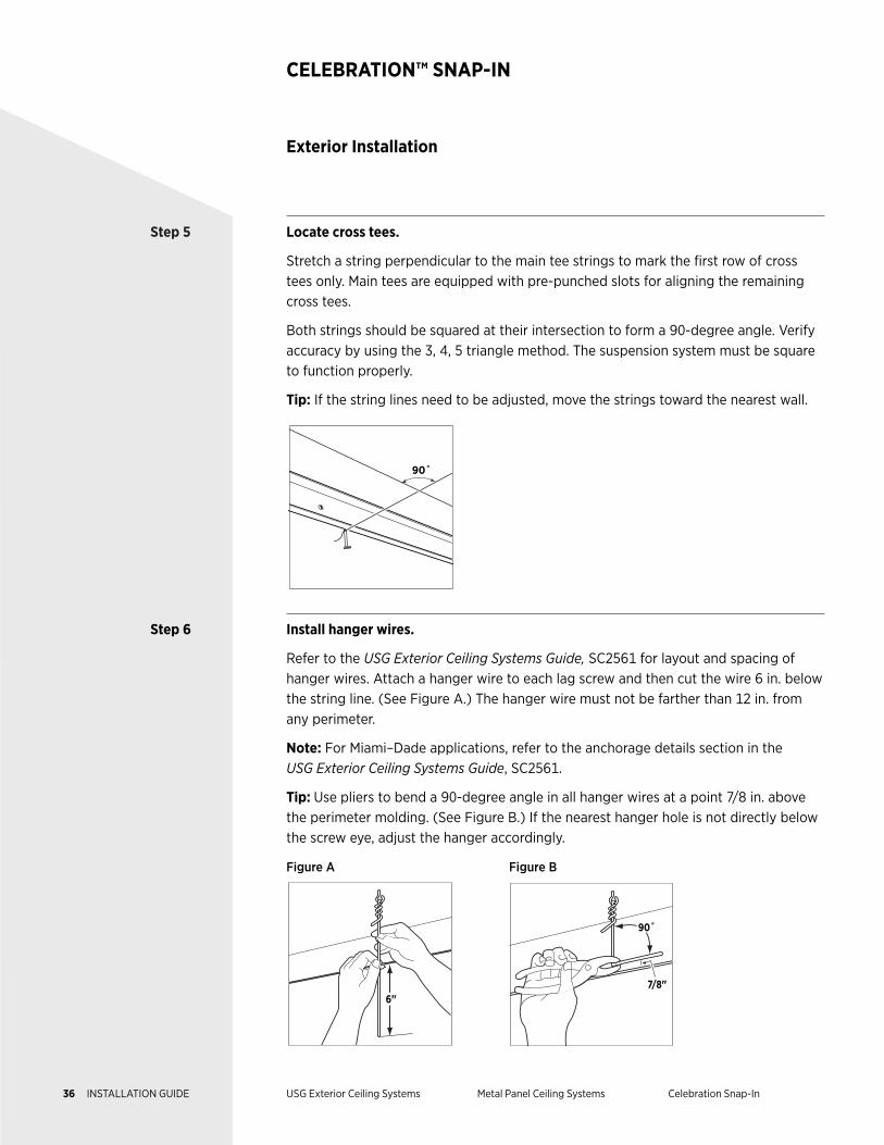
Step 5 Locate cross tees.
Stretch a string perpendicular to the main tee strings to mark the first row of cross tees only. Main tees are equipped with pre-punched slots for aligning the remaining cross tees.
Both strings should be squared at their intersection to form a 90-degree angle. Verify accuracy by using the 3, 4, 5 triangle method. The suspension system must be square to function properly.
Tip: If the string lines need to be adjusted, move the strings toward the nearest wall.
90˚
Step 6 Install hanger wires.
Refer to the USG Exterior Ceiling Systems Guide, SC2561 for layout and spacing of hanger wires. Attach a hanger wire to each lag screw and then cut the wire 6 in. below the string line. (See Figure A.) The hanger wire must not be farther than 12 in. from any perimeter.
Note: For Miami–Dade applications, refer to the anchorage details section in the USG Exterior Ceiling Systems Guide, SC2561.
Tip: Use pliers to bend a 90-degree angle in all hanger wires at a point 7/8 in. above the perimeter molding. (See Figure B.) If the nearest hanger hole is not directly below the screw eye, adjust the hanger accordingly.
Figure A Figure B
6"
7/8"
90˚
Exterior Installation
CELEBRATION™ SNAP-IN
36 INSTALLATION GUIDE USG Exterior Ceiling Systems Metal Panel Ceiling Systems Celebration Snap-In
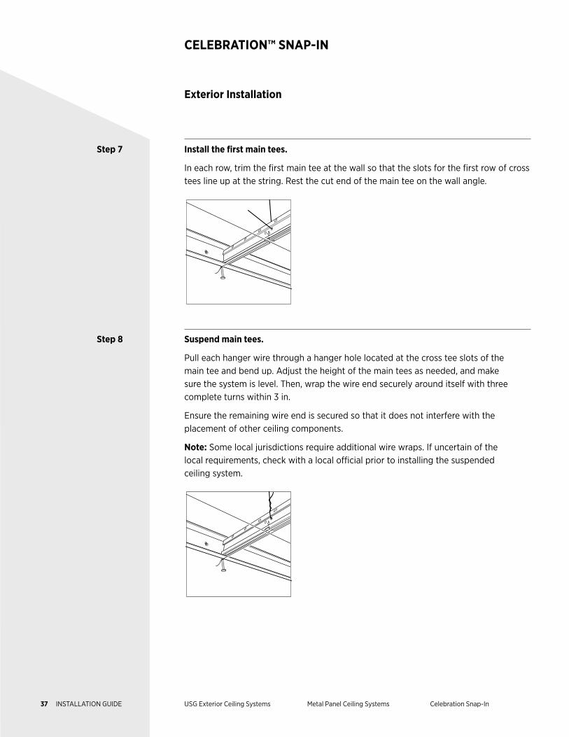
Step 7 Install the first main tees.
In each row, trim the first main tee at the wall so that the slots for the first row of cross tees line up at the string. Rest the cut end of the main tee on the wall angle.
Step 8 Suspend main tees.
Pull each hanger wire through a hanger hole located at the cross tee slots of the main tee and bend up. Adjust the height of the main tees as needed, and make sure the system is level. Then, wrap the wire end securely around itself with three complete turns within 3 in.
Ensure the remaining wire end is secured so that it does not interfere with the placement of other ceiling components.
Note: Some local jurisdictions require additional wire wraps. If uncertain of the local requirements, check with a local official prior to installing the suspended ceiling system.
Exterior Installation
CELEBRATION™ SNAP-IN
37 INSTALLATION GUIDE USG Exterior Ceiling Systems Metal Panel Ceiling Systems Celebration Snap-In
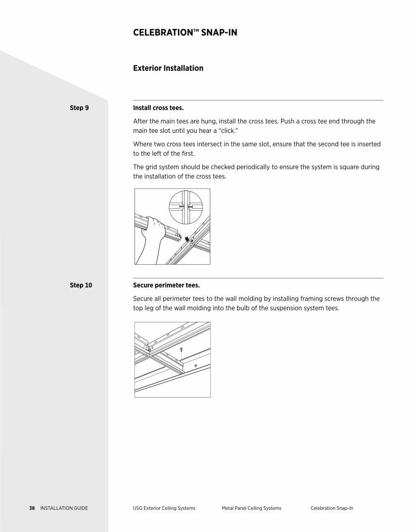
Step 9 Install cross tees.
After the main tees are hung, install the cross tees. Push a cross tee end through the main tee slot until you hear a “click.”
Where two cross tees intersect in the same slot, ensure that the second tee is inserted to the left of the first.
The grid system should be checked periodically to ensure the system is square during the installation of the cross tees.
Step 10 Secure perimeter tees.
Secure all perimeter tees to the wall molding by installing framing screws through the top leg of the wall molding into the bulb of the suspension system tees.
Exterior Installation
CELEBRATION™ SNAP-IN
38 INSTALLATION GUIDE USG Exterior Ceiling Systems Metal Panel Ceiling Systems Celebration Snap-In
Exterior Installation
CELEBRATION™ SNAP-IN
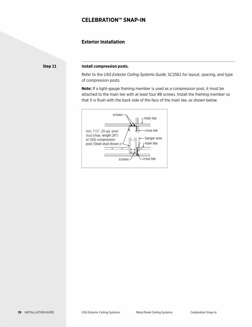
Step 11 Install compression posts.
Refer to the USG Exterior Ceiling Systems Guide, SC2561 for layout, spacing, and type of compression posts.
Note: If a light-gauge framing member is used as a compression post, it must be attached to the main tee with at least four #8 screws. Install the framing member so that it is flush with the back side of the face of the main tee, as shown below.
screws
screws
cross tee
cross tee
hanger wire
min. 1 5/8", 20-ga. steel stud (max. length 24") or USG compression post (Steel stud shown.) main tee
main tee
39 INSTALLATION GUIDE USG Exterior Ceiling Systems Metal Panel Ceiling Systems Celebration Snap-In
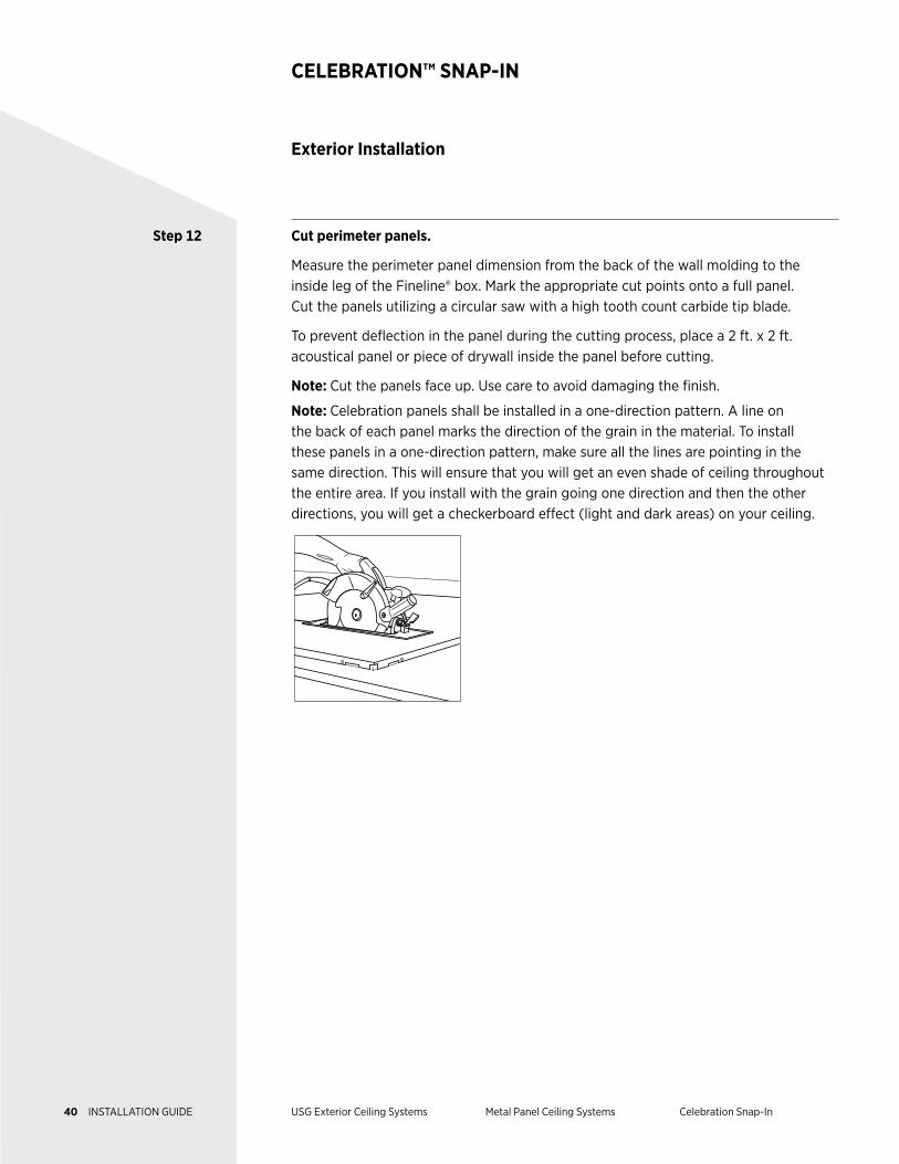
Step 12 Cut perimeter panels.
Measure the perimeter panel dimension from the back of the wall molding to the inside leg of the Fineline® box. Mark the appropriate cut points onto a full panel. Cut the panels utilizing a circular saw with a high tooth count carbide tip blade.
To prevent deflection in the panel during the cutting process, place a 2 ft. x 2 ft. acoustical panel or piece of drywall inside the panel before cutting.
Note: Cut the panels face up. Use care to avoid damaging the finish.
Note: Celebration panels shall be installed in a one-direction pattern. A line on the back of each panel marks the direction of the grain in the material. To install these panels in a one-direction pattern, make sure all the lines are pointing in the same direction. This will ensure that you will get an even shade of ceiling throughout the entire area. If you install with the grain going one direction and then the other directions, you will get a checkerboard effect (light and dark areas) on your ceiling.
Exterior Installation
CELEBRATION™ SNAP-IN
40 INSTALLATION GUIDE USG Exterior Ceiling Systems Metal Panel Ceiling Systems Celebration Snap-In
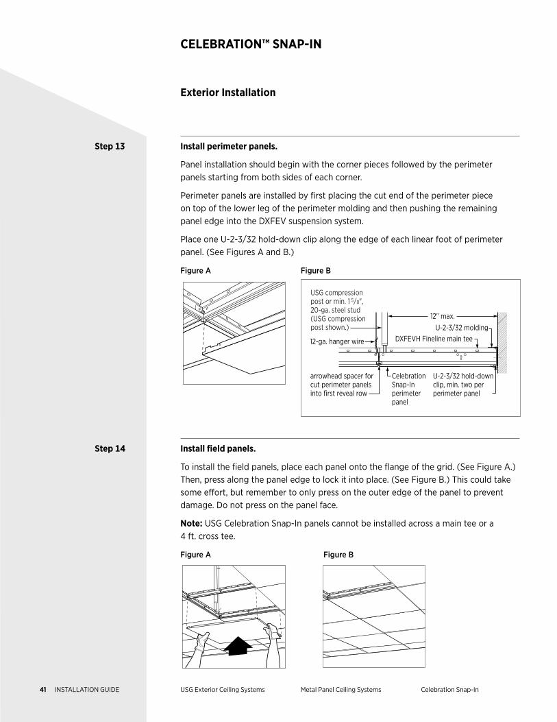
Step 13 Install perimeter panels.
Panel installation should begin with the corner pieces followed by the perimeter panels starting from both sides of each corner.
Perimeter panels are installed by first placing the cut end of the perimeter piece on top of the lower leg of the perimeter molding and then pushing the remaining panel edge into the DXFEV suspension system.
Place one U-2-3/32 hold-down clip along the edge of each linear foot of perimeter panel. (See Figures A and B.)
Figure A Figure B
12-ga. hanger wire
Celebration Snap-In perimeter panel
U-2-3/32 hold-downclip, min. two per perimeter panel
U-2-3/32 moldingDXFEVH Fineline main tee
12" max.
arrowhead spacer for cut perimeter panels into first reveal row
USG compression post or min. 1 5/8", 20-ga. steel stud (USG compression post shown.)
Step 14 Install field panels.
To install the field panels, place each panel onto the flange of the grid. (See Figure A.) Then, press along the panel edge to lock it into place. (See Figure B.) This could take some effort, but remember to only press on the outer edge of the panel to prevent damage. Do not press on the panel face.
Note: USG Celebration Snap-In panels cannot be installed across a main tee or a 4 ft. cross tee.
Figure A Figure B
Exterior Installation
CELEBRATION™ SNAP-IN
41 INSTALLATION GUIDE USG Exterior Ceiling Systems Metal Panel Ceiling Systems Celebration Snap-In
Exterior Installation
CELEBRATION™ SNAP-IN
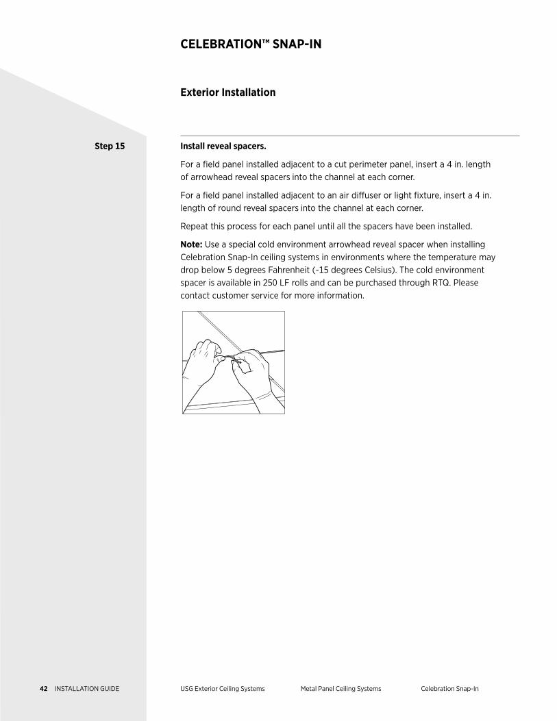
Step 15 Install reveal spacers.
For a field panel installed adjacent to a cut perimeter panel, insert a 4 in. length of arrowhead reveal spacers into the channel at each corner.
For a field panel installed adjacent to an air diffuser or light fixture, insert a 4 in. length of round reveal spacers into the channel at each corner.
Repeat this process for each panel until all the spacers have been installed.
Note: Use a special cold environment arrowhead reveal spacer when installing Celebration Snap-In ceiling systems in environments where the temperature may drop below 5 degrees Fahrenheit (-15 degrees Celsius). The cold environment spacer is available in 250 LF rolls and can be purchased through RTQ. Please contact customer service for more information.
42 INSTALLATION GUIDE USG Exterior Ceiling Systems Metal Panel Ceiling Systems Celebration Snap-In
DESCRIPTION USG Celebration™ Torsion Spring panels combine a unique, monolithic
appearance with the hidden strength and corrosion resistance of aluminum.
Celebration Torsion Spring panels are supported by testing for a variety of
installation requirements, including Miami–Dade NOA, for exterior applications
with proper bracing and framing.
This guide outlines the design considerations, test results, and construction
details for the installation of the USG Celebration exterior ceiling system.
USG exterior assemblies were tested per UL 580, UL 1897, TAS 202, and
TAS 203, and listed in PEI Evaluation Report, PER-12055.
NOTES Follow proper safety and industrial hygiene practices while handling and installing all products and systems. Take necessary precautions and wear appropriate personal protective equipment as needed. For product safety information and personal protective equipment recommendations review the safety data sheet. When removing or installing ceiling panels from grid, we recommend wearing a dust mask, cut-resistant gloves, and eye protection. Provide drop cloths to cover and protect furnishings below. When using a ladder or lift, follow the equipment manufacturer’s precautions, instructions, and safety guidelines.
All ceiling products and systems must be installed and maintained in accordance with current USG written instructions and in compliance with ASTM C636, ASTM E580, CISCA, and standard industry practices.
Care must be taken to safeguard products from damage during delivery and while they are stored at the jobsite. The products must always be protected from vibration, chemical fumes, and direct contact with water both before and after installation.
METAL PANEL CEILING SYSTEMS
Exterior Ceiling Applications
Celebration™ Torsion Spring
43 INSTALLATION GUIDE USG Exterior Ceiling Systems Metal Panel Ceiling Systems Celebration Torsion Spring
Components
CELEBRATION™ TORSION SPRING
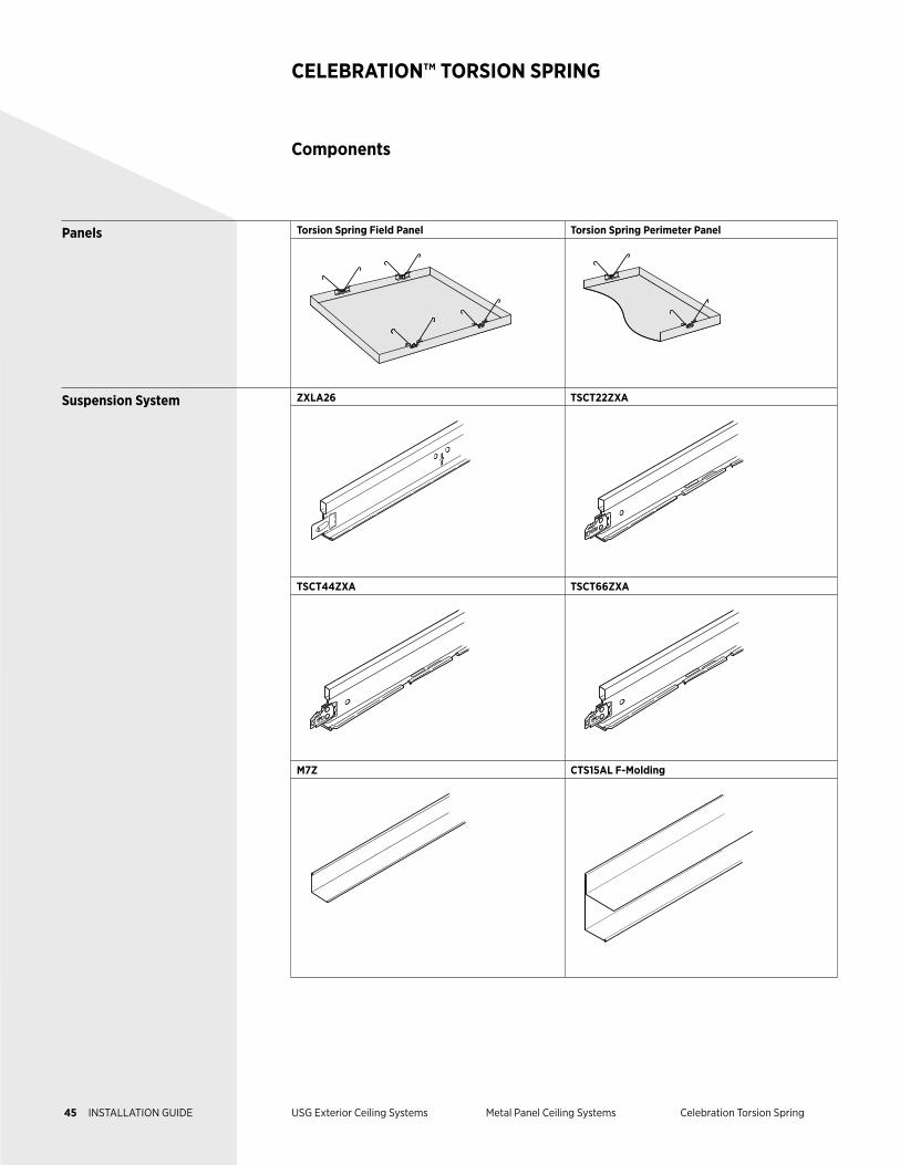
Panels Celebration Torsion Spring panels are used in aluminum ceiling systems installed with torsion springs fixed to the panels, which are inserted into engineered slots underneath the suspension.
Field panels are installed in the field of the ceiling layout, not on the perimeter.
Perimeter panels are installed on the edge or perimeter of the room. They may be cut to length.
Suspension System ZXLA26 are 12 ft., heavy duty main tees made of G90 hot-dipped galvanized steel with aluminum caps, baked-on polyester paint, and a stainless steel clip for increased corrosion protection.
TSCT22ZXA are 2 ft. cross tees made of G90 hot-dipped galvanized steel with aluminum caps, baked-on polyester paint, and a stainless steel clip for increased corrosion protection.
TSCT44ZXA are 4 ft. cross tees made of G90 hot-dipped galvanized steel with aluminum caps, baked-on polyester paint, and a stainless steel clip for increased corrosion protection.
TSCT66ZXA are 6 ft. cross tees made of G90 hot-dipped galvanized steel with aluminum caps, baked-on polyester paint, and a stainless steel clip for increased corrosion protection.
M7Z are 12 ft. wall moldings made of hot-dipped galvanized steel.
CTS15AL are 10 ft. aluminum F-molds for use specifically with Celebration Torsion Spring systems to eliminate the need for double rows of M7Z.
Accessories Compression posts are rigid metal supports attached to the ZXLA26 main tees at each hanger wire location and to the building structure. Compression posts prevent upward movement and are required by code.
Hanger wires are a minimum 12-gauge galvanized, annealed wire used to support suspended ceiling systems from the structure.
T15 hold-down clips are perimeter hold-down clips used to press cut perimeter panels firmly into the lower leg of the wall molding.
44 INSTALLATION GUIDE USG Exterior Ceiling Systems Metal Panel Ceiling Systems Celebration Torsion Spring
Components
CELEBRATION™ TORSION SPRING
Panels Torsion Spring Field Panel Torsion Spring Perimeter Panel
Suspension System ZXLA26 TSCT22ZXA
TSCT44ZXA TSCT66ZXA
M7Z CTS15AL F-Molding
45 INSTALLATION GUIDE USG Exterior Ceiling Systems Metal Panel Ceiling Systems Celebration Torsion Spring
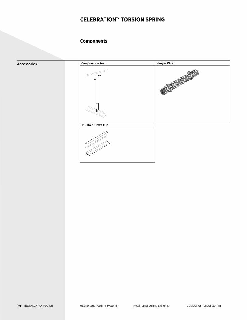
Accessories Compression Post Hanger Wire
T15 Hold-Down Clip
Components
CELEBRATION™ TORSION SPRING
46 INSTALLATION GUIDE USG Exterior Ceiling Systems Metal Panel Ceiling Systems Celebration Torsion Spring
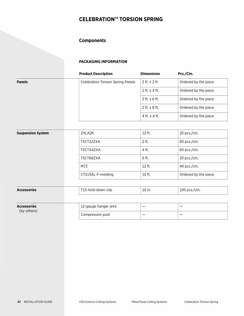
Product Description Dimensions Pcs./Ctn.
Panels Celebration Torsion Spring Panels 2 ft. x 2 ft. Ordered by the piece
2 ft. x 4 ft. Ordered by the piece
2 ft. x 6 ft. Ordered by the piece
2 ft. x 8 ft. Ordered by the piece
4 ft. x 4 ft. Ordered by the piece
Suspension System ZXLA26 12 ft. 20 pcs./ctn.
TSCT22ZXA 2 ft. 60 pcs./ctn.
TSCT44ZXA 4 ft. 60 pcs./ctn.
TSCT66ZXA 6 ft. 20 pcs./ctn.
M7Z 12 ft. 40 pcs./ctn.
CTS15AL F-molding 10 ft. Ordered by the piece
Accessories T15 hold-down clip 10 in. 100 pcs./ctn.
Accessories (by others)
12-gauge hanger wire — —
Compression post — —
Components
CELEBRATION™ TORSION SPRING
PACKAGING INFORMATION
47 INSTALLATION GUIDE USG Exterior Ceiling Systems Metal Panel Ceiling Systems Celebration Torsion Spring
Exterior Installation
CELEBRATION™ TORSION SPRING
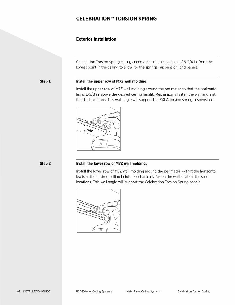
Celebration Torsion Spring ceilings need a minimum clearance of 6-3/4 in. from the lowest point in the ceiling to allow for the springs, suspension, and panels.
Step 1 Install the upper row of M7Z wall molding.
Install the upper row of M7Z wall molding around the perimeter so that the horizontal leg is 1-5/8 in. above the desired ceiling height. Mechanically fasten the wall angle at the stud locations. This wall angle will support the ZXLA torsion spring suspensions.
1-5/8"
Step 2 Install the lower row of M7Z wall molding.
Install the lower row of M7Z wall molding around the perimeter so that the horizontal leg is at the desired ceiling height. Mechanically fasten the wall angle at the stud locations. This wall angle will support the Celebration Torsion Spring panels.
48 INSTALLATION GUIDE USG Exterior Ceiling Systems Metal Panel Ceiling Systems Celebration Torsion Spring
Exterior Installation
CELEBRATION™ TORSION SPRING
Steps 1–2 Alternate continued
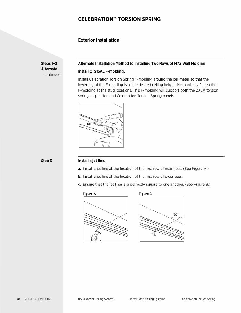
Alternate Installation Method to Installing Two Rows of M7Z Wall Molding
Install CTS15AL F-molding.
Install Celebration Torsion Spring F-molding around the perimeter so that the lower leg of the F-molding is at the desired ceiling height. Mechanically fasten the F-molding at the stud locations. This F-molding will support both the ZXLA torsion spring suspension and Celebration Torsion Spring panels.
Step 3 Install a jet line.
a. Install a jet line at the location of the first row of main tees. (See Figure A.)
b. Install a jet line at the location of the first row of cross tees.
c. Ensure that the jet lines are perfectly square to one another. (See Figure B.)
Figure A Figure B
90˚
49 INSTALLATION GUIDE USG Exterior Ceiling Systems Metal Panel Ceiling Systems Celebration Torsion Spring
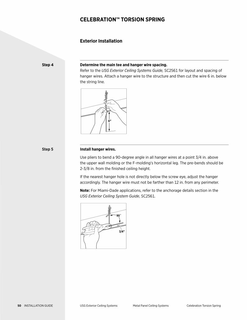
Step 4 Determine the main tee and hanger wire spacing.Refer to the USG Exterior Ceiling Systems Guide, SC2561 for layout and spacing of hanger wires. Attach a hanger wire to the structure and then cut the wire 6 in. below the string line.
6"
Step 5 Install hanger wires.
Use pliers to bend a 90-degree angle in all hanger wires at a point 3/4 in. above the upper wall molding or the F-molding's horizontal leg. The pre-bends should be 2-3/8 in. from the finished ceiling height.
If the nearest hanger hole is not directly below the screw eye, adjust the hanger accordingly. The hanger wire must not be farther than 12 in. from any perimeter.
Note: For Miami-Dade applications, refer to the anchorage details section in the USG Exterior Ceiling System Guide, SC2561.
3/4"
90˚
Exterior Installation
CELEBRATION™ TORSION SPRING
50 INSTALLATION GUIDE USG Exterior Ceiling Systems Metal Panel Ceiling Systems Celebration Torsion Spring
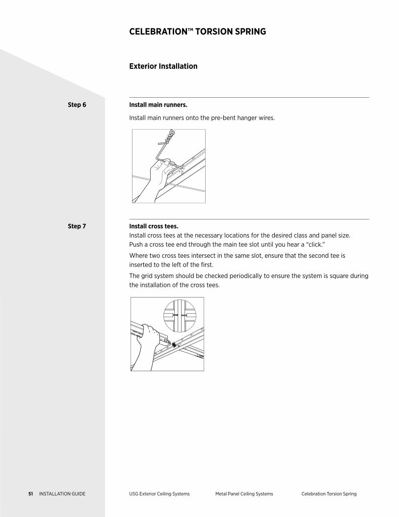
Step 6 Install main runners.
Install main runners onto the pre-bent hanger wires.
Step 7 Install cross tees.Install cross tees at the necessary locations for the desired class and panel size. Push a cross tee end through the main tee slot until you hear a “click.”
Where two cross tees intersect in the same slot, ensure that the second tee is inserted to the left of the first.
The grid system should be checked periodically to ensure the system is square during the installation of the cross tees.
Exterior Installation
CELEBRATION™ TORSION SPRING
51 INSTALLATION GUIDE USG Exterior Ceiling Systems Metal Panel Ceiling Systems Celebration Torsion Spring
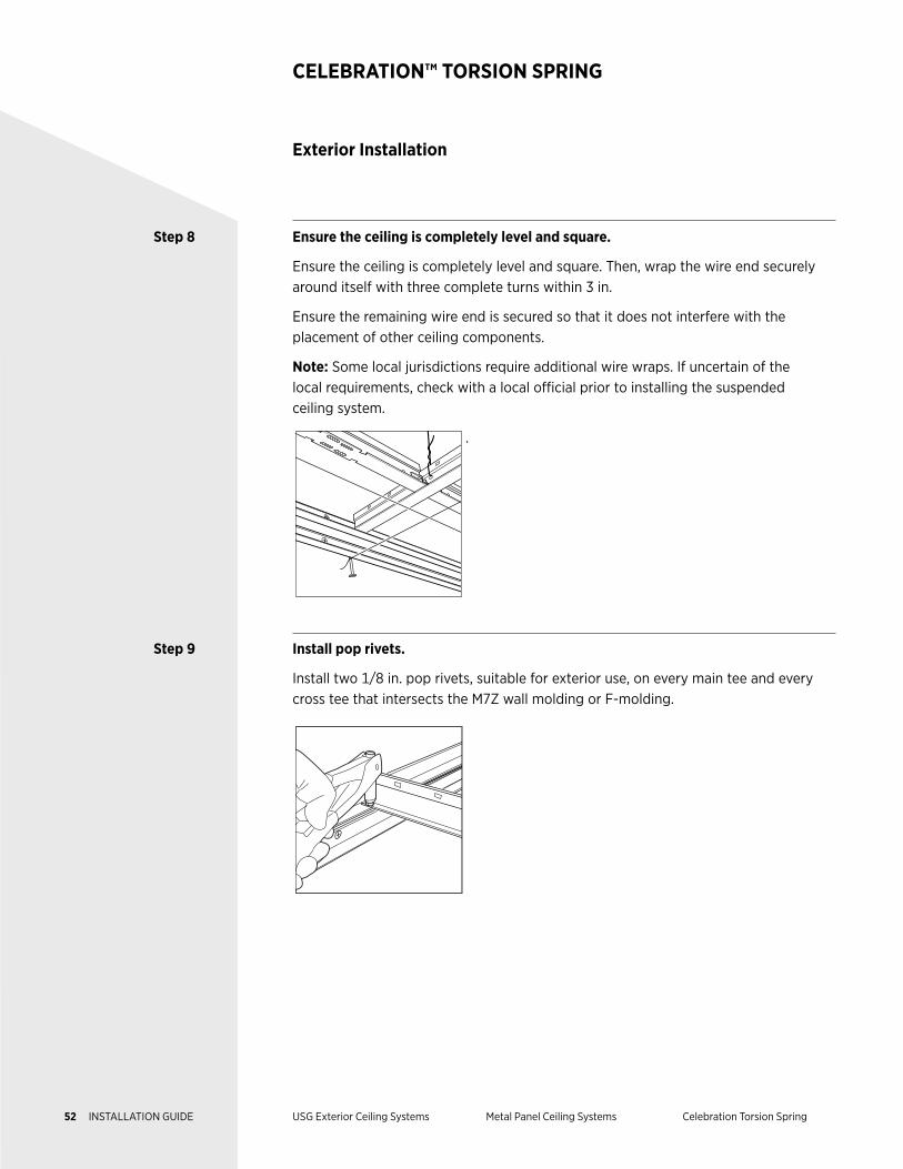
Step 8 Ensure the ceiling is completely level and square.
Ensure the ceiling is completely level and square. Then, wrap the wire end securely around itself with three complete turns within 3 in.
Ensure the remaining wire end is secured so that it does not interfere with the placement of other ceiling components.
Note: Some local jurisdictions require additional wire wraps. If uncertain of the local requirements, check with a local official prior to installing the suspended ceiling system.
.
Step 9 Install pop rivets.
Install two 1/8 in. pop rivets, suitable for exterior use, on every main tee and every cross tee that intersects the M7Z wall molding or F-molding.
Exterior Installation
CELEBRATION™ TORSION SPRING
52 INSTALLATION GUIDE USG Exterior Ceiling Systems Metal Panel Ceiling Systems Celebration Torsion Spring
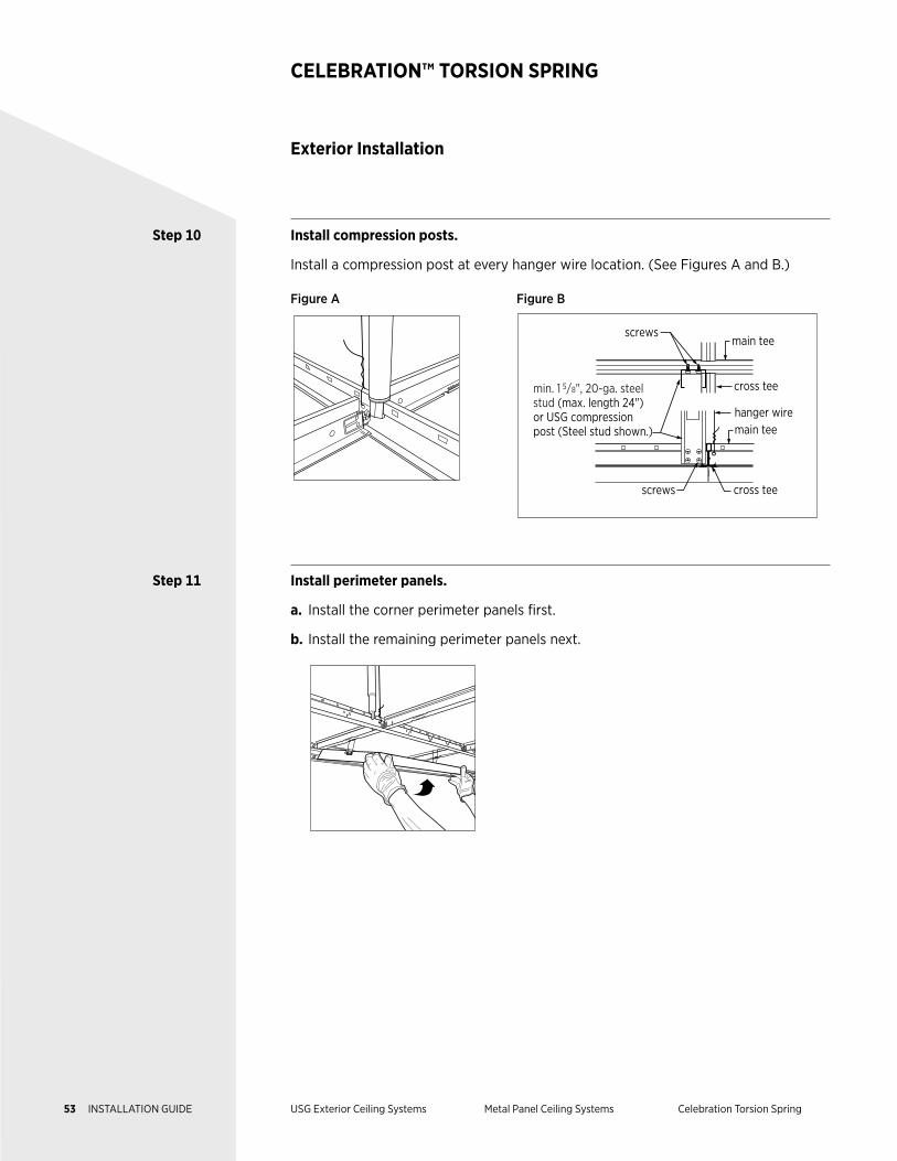
Step 10 Install compression posts.
Install a compression post at every hanger wire location. (See Figures A and B.)
Figure A Figure B
screws
screws
cross tee
cross tee
hanger wire
min. 1 5/8", 20-ga. steel stud (max. length 24") or USG compression post (Steel stud shown.) main tee
main tee
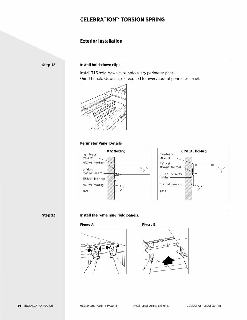
Step 11 Install perimeter panels.
a. Install the corner perimeter panels first.
b. Install the remaining perimeter panels next.
Exterior Installation
CELEBRATION™ TORSION SPRING
53 INSTALLATION GUIDE USG Exterior Ceiling Systems Metal Panel Ceiling Systems Celebration Torsion Spring
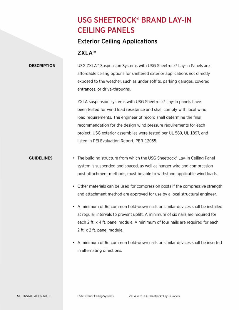
Step 12 Install hold-down clips.
Install T15 hold-down clips onto every perimeter panel. One T15 hold-down clip is required for every foot of perimeter panel.
Perimeter Panel Details
M7Z Moldingmain tee orcross tee
M7Z wall molding
1/8" rivet (two per tee end)
T15 hold-down clip
M7Z wall molding
panel
CTS15AL Molding
CTS15AL perimeter molding
1/8" rivet (two per tee end)
T15 hold-down clip
panel
main tee orcross tee
Step 13 Install the remaining field panels.
Figure A Figure B
Exterior Installation
CELEBRATION™ TORSION SPRING
54 INSTALLATION GUIDE USG Exterior Ceiling Systems Metal Panel Ceiling Systems Celebration Torsion Spring
DESCRIPTION USG ZXLA™ Suspension Systems with USG Sheetrock® Lay-In Panels are
affordable ceiling options for sheltered exterior applications not directly
exposed to the weather, such as under soffits, parking garages, covered
entrances, or drive-throughs.
ZXLA suspension systems with USG Sheetrock® Lay-In panels have
been tested for wind load resistance and shall comply with local wind
load requirements. The engineer of record shall determine the final
recommendation for the design wind pressure requirements for each
project. USG exterior assemblies were tested per UL 580, UL 1897, and
listed in PEI Evaluation Report, PER-12055.
GUIDELINES • The building structure from which the USG Sheetrock® Lay-In Ceiling Panel
system is suspended and spaced, as well as hanger wire and compression
post attachment methods, must be able to withstand applicable wind loads.
• Other materials can be used for compression posts if the compressive strength
and attachment method are approved for use by a local structural engineer.
• A minimum of 6d common hold-down nails or similar devices shall be installed
at regular intervals to prevent uplift. A minimum of six nails are required for
each 2 ft. x 4 ft. panel module. A minimum of four nails are required for each
2 ft. x 2 ft. panel module.
• A minimum of 6d common hold-down nails or similar devices shall be inserted
in alternating directions.
USG SHEETROCK® BRAND LAY-IN CEILING PANELS Exterior Ceiling Applications
ZXLA™
55 INSTALLATION GUIDE USG Exterior Ceiling Systems ZXLA with USG Sheetrock® Lay-In Panels
ZXLA™ WITH USG SHEETROCK® LAY-IN PANELS
GUIDELINES • A minimum of 6d common hold-down nails or similar devices may be installed
through the hanger wire holes, cross tee clip holes, and through a field-
punched hole in the web of the tee.
• The architect’s details must cover the design and location of expansion joints
and meet all applicable building code requirements.
NOTES Follow proper safety and industrial hygiene practices while handling and installing all products and systems. Take necessary precautions and wear appropriate personal protective equipment as needed. For product safety information and personal protective equipment recommendations review the safety data sheet. When removing or installing ceiling panels from grid, we recommend wearing a dust mask, cut-resistant gloves, and eye protection. Provide drop cloths to cover and protect furnishings below. When using a ladder or lift, follow the equipment manufacturer’s precautions, instructions, and safety guidelines.
All ceiling products and systems must be installed and maintained in accordance with current USG written instructions and in compliance with ASTM C636, ASTM E580, CISCA, and standard industry practices.
Care must be taken to safeguard products from damage during delivery and while they are stored at the jobsite. The products must always be protected from vibration, chemical fumes, and direct contact with water both before and after installation.
56 INSTALLATION GUIDE USG Exterior Ceiling Systems ZXLA with USG Sheetrock® Lay-In Panels
Components
ZXLA™ WITH USG SHEETROCK® LAY-IN PANELS
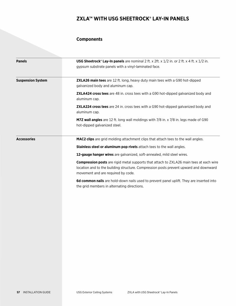
Panels USG Sheetrock® Lay-In panels are nominal 2 ft. x 2ft. x 1/2 in. or 2 ft. x 4 ft. x 1/2 in. gypsum substrate panels with a vinyl-laminated face.
Suspension System ZXLA26 main tees are 12 ft. long, heavy duty main tees with a G90 hot-dipped galvanized body and aluminum cap.
ZXLA424 cross tees are 48 in. cross tees with a G90 hot-dipped galvanized body and aluminum cap.
ZXLA224 cross tees are 24 in. cross tees with a G90 hot-dipped galvanized body and aluminum cap.
M7Z wall angles are 12 ft. long wall moldings with 7/8 in. x 7/8 in. legs made of G90 hot-dipped galvanized steel.
Accessories MAC2 clips are grid molding attachment clips that attach tees to the wall angles.
Stainless steel or aluminum pop rivets attach tees to the wall angles.
12-gauge hanger wires are galvanized, soft-annealed, mild steel wires.
Compression posts are rigid metal supports that attach to ZXLA26 main tees at each wire location and to the building structure. Compression posts prevent upward and downward movement and are required by code.
6d common nails are hold-down nails used to prevent panel uplift. They are inserted into the grid members in alternating directions.
57 INSTALLATION GUIDE USG Exterior Ceiling Systems ZXLA with USG Sheetrock® Lay-In Panels
Components
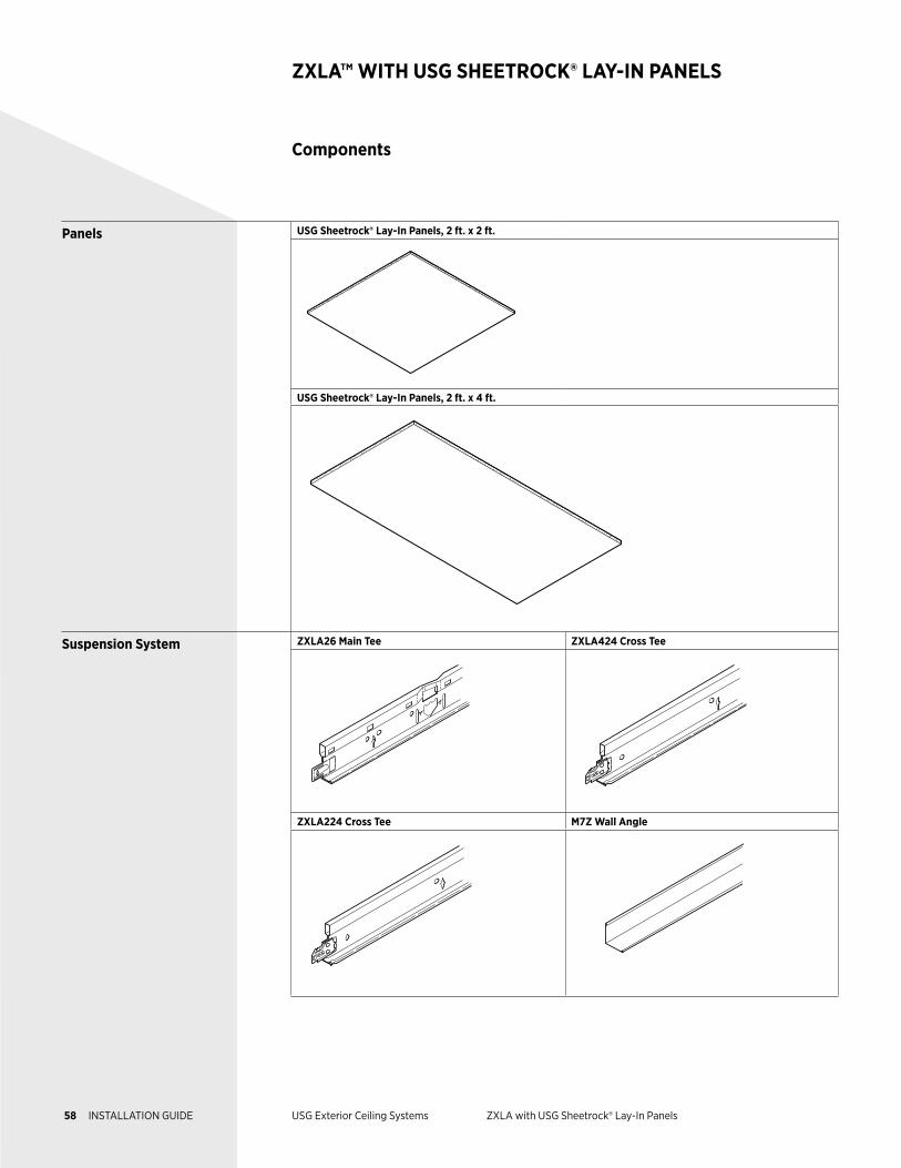
ZXLA™ WITH USG SHEETROCK® LAY-IN PANELS
Panels USG Sheetrock® Lay-In Panels, 2 ft. x 2 ft.
USG Sheetrock® Lay-In Panels, 2 ft. x 4 ft.
Suspension System ZXLA26 Main Tee ZXLA424 Cross Tee
ZXLA224 Cross Tee M7Z Wall Angle
58 INSTALLATION GUIDE USG Exterior Ceiling Systems ZXLA with USG Sheetrock® Lay-In Panels
Components
ZXLA™ WITH USG SHEETROCK® LAY-IN PANELS
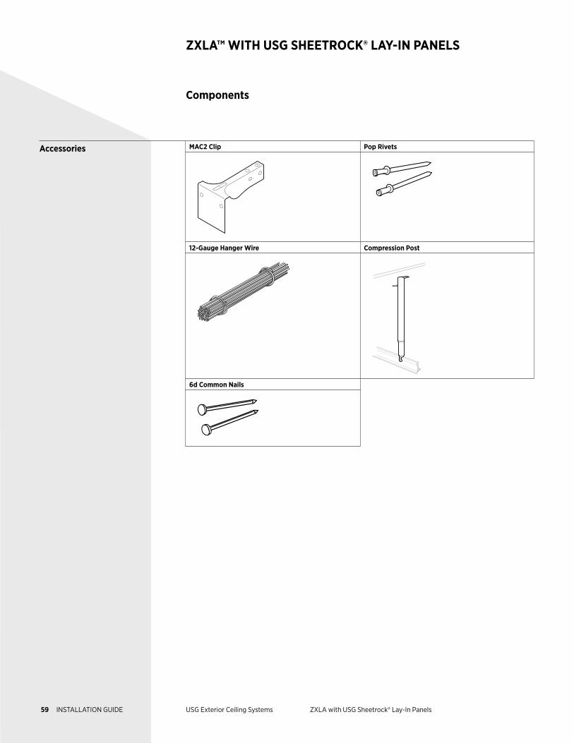
Accessories MAC2 Clip Pop Rivets
12-Gauge Hanger Wire Compression Post
6d Common Nails
59 INSTALLATION GUIDE USG Exterior Ceiling Systems ZXLA with USG Sheetrock® Lay-In Panels
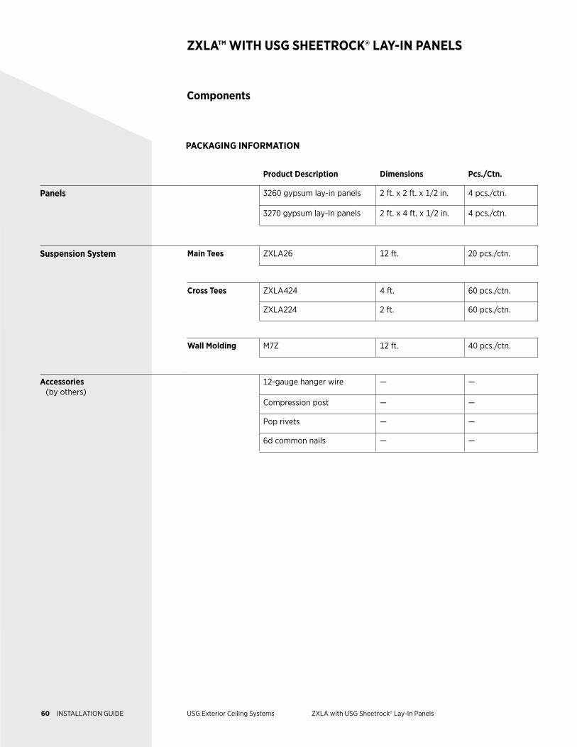
Product Description Dimensions Pcs./Ctn.
Panels 3260 gypsum lay-in panels 2 ft. x 2 ft. x 1/2 in. 4 pcs./ctn.
3270 gypsum lay-In panels 2 ft. x 4 ft. x 1/2 in. 4 pcs./ctn.
Suspension System Main Tees ZXLA26 12 ft. 20 pcs./ctn.
Cross Tees ZXLA424 4 ft. 60 pcs./ctn.
ZXLA224 2 ft. 60 pcs./ctn.
Wall Molding M7Z 12 ft. 40 pcs./ctn.
Accessories (by others)
12-gauge hanger wire — —
Compression post — —
Pop rivets — —
6d common nails — —
Components
ZXLA™ WITH USG SHEETROCK® LAY-IN PANELS
PACKAGING INFORMATION
60 INSTALLATION GUIDE USG Exterior Ceiling Systems ZXLA with USG Sheetrock® Lay-In Panels
Exterior Installation
ZXLA™ WITH USG SHEETROCK® LAY-IN PANELS
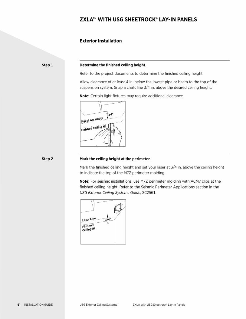
Step 1 Determine the finished ceiling height.
Refer to the project documents to determine the finished ceiling height.
Allow clearance of at least 4 in. below the lowest pipe or beam to the top of the suspension system. Snap a chalk line 3/4 in. above the desired ceiling height.
Note: Certain light fixtures may require additional clearance.
≥4"
Finished Ceiling Ht.Top of Assembly
Step 2 Mark the ceiling height at the perimeter.
Mark the finished ceiling height and set your laser at 3/4 in. above the ceiling height to indicate the top of the M7Z perimeter molding.
Note: For seismic installations, use M7Z perimeter molding with ACM7 clips at the finished ceiling height. Refer to the Seismic Perimeter Applications section in the USG Exterior Ceiling Systems Guide, SC2561.
3/4"
Finished
Ceiling Ht.
Laser Line
61 INSTALLATION GUIDE USG Exterior Ceiling Systems ZXLA with USG Sheetrock® Lay-In Panels
Exterior Installation
ZXLA™ WITH USG SHEETROCK® LAY-IN PANELS
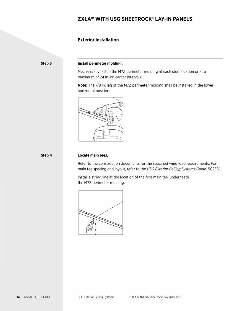
Step 3 Install perimeter molding.
Mechanically fasten the M7Z perimeter molding at each stud location or at a maximum of 24 in. on center intervals.
Note: The 7/8 in. leg of the M7Z perimeter molding shall be installed in the lower horizontal position.
Step 4 Locate main tees.
Refer to the construction documents for the specified wind load requirements. For main tee spacing and layout, refer to the USG Exterior Ceiling Systems Guide, SC2561.
Install a string line at the location of the first main tee, underneath the M7Z perimeter molding.
62 INSTALLATION GUIDE USG Exterior Ceiling Systems ZXLA with USG Sheetrock® Lay-In Panels
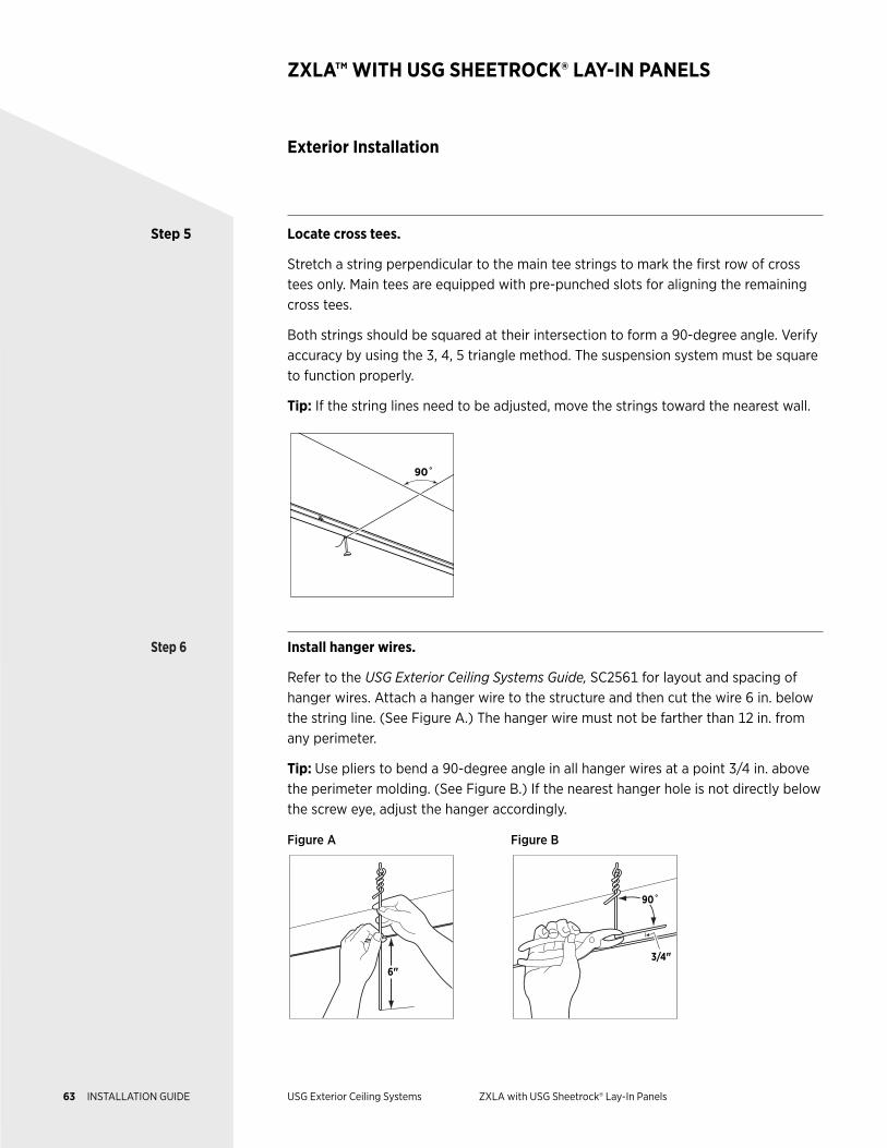
Step 5 Locate cross tees.
Stretch a string perpendicular to the main tee strings to mark the first row of cross tees only. Main tees are equipped with pre-punched slots for aligning the remaining cross tees.
Both strings should be squared at their intersection to form a 90-degree angle. Verify accuracy by using the 3, 4, 5 triangle method. The suspension system must be square to function properly.
Tip: If the string lines need to be adjusted, move the strings toward the nearest wall.
90˚
Step 6 Install hanger wires.
Refer to the USG Exterior Ceiling Systems Guide, SC2561 for layout and spacing of hanger wires. Attach a hanger wire to the structure and then cut the wire 6 in. below the string line. (See Figure A.) The hanger wire must not be farther than 12 in. from any perimeter.
Tip: Use pliers to bend a 90-degree angle in all hanger wires at a point 3/4 in. above the perimeter molding. (See Figure B.) If the nearest hanger hole is not directly below the screw eye, adjust the hanger accordingly.
Figure A Figure B
6"
3/4"
90˚
Exterior Installation
ZXLA™ WITH USG SHEETROCK® LAY-IN PANELS
63 INSTALLATION GUIDE USG Exterior Ceiling Systems ZXLA with USG Sheetrock® Lay-In Panels
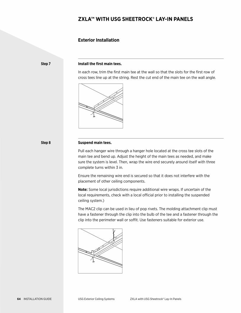
Step 7 Install the first main tees.
In each row, trim the first main tee at the wall so that the slots for the first row of cross tees line up at the string. Rest the cut end of the main tee on the wall angle.
Step 8 Suspend main tees.
Pull each hanger wire through a hanger hole located at the cross tee slots of the main tee and bend up. Adjust the height of the main tees as needed, and make sure the system is level. Then, wrap the wire end securely around itself with three complete turns within 3 in.
Ensure the remaining wire end is secured so that it does not interfere with the placement of other ceiling components.
Note: Some local jurisdictions require additional wire wraps. If uncertain of the local requirements, check with a local official prior to installing the suspended ceiling system.)
The MAC2 clip can be used in lieu of pop rivets. The molding attachment clip must have a fastener through the clip into the bulb of the tee and a fastener through the clip into the perimeter wall or soffit. Use fasteners suitable for exterior use.
Exterior Installation
ZXLA™ WITH USG SHEETROCK® LAY-IN PANELS
64 INSTALLATION GUIDE USG Exterior Ceiling Systems ZXLA with USG Sheetrock® Lay-In Panels
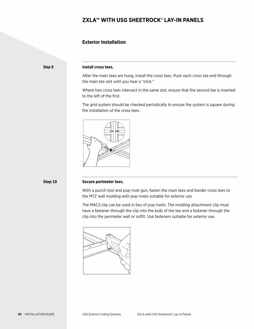
Step 9 Install cross tees.
After the main tees are hung, install the cross tees. Push each cross tee end through the main tee slot until you hear a “click.”
Where two cross tees intersect in the same slot, ensure that the second tee is inserted to the left of the first.
The grid system should be checked periodically to ensure the system is square during the installation of the cross tees.
Step 10 Secure perimeter tees.
With a punch tool and pop-rivet gun, fasten the main tees and border cross tees to the M7Z wall molding with pop rivets suitable for exterior use.
The MAC2 clip can be used in lieu of pop rivets. The molding attachment clip must have a fastener through the clip into the bulb of the tee and a fastener through the clip into the perimeter wall or soffit. Use fasteners suitable for exterior use.
Exterior Installation
ZXLA™ WITH USG SHEETROCK® LAY-IN PANELS
65 INSTALLATION GUIDE USG Exterior Ceiling Systems ZXLA with USG Sheetrock® Lay-In Panels
Exterior Installation
ZXLA™ WITH USG SHEETROCK® LAY-IN PANELS
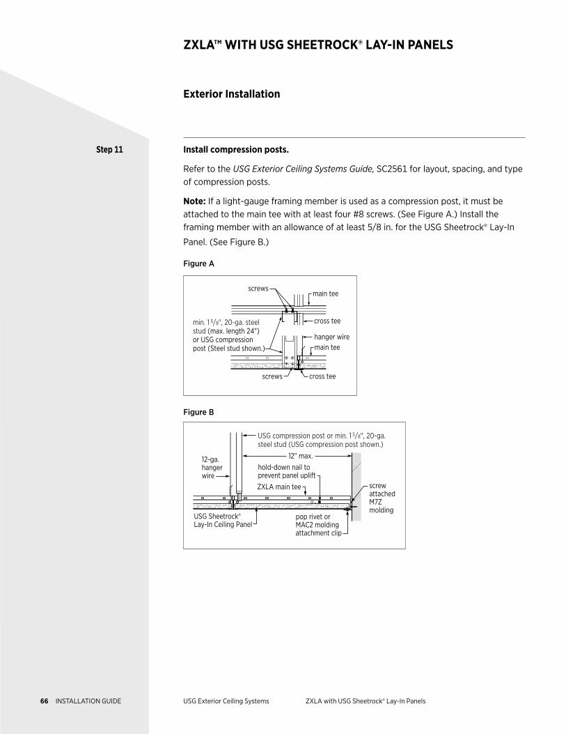
Step 11 Install compression posts.
Refer to the USG Exterior Ceiling Systems Guide, SC2561 for layout, spacing, and type of compression posts.
Note: If a light-gauge framing member is used as a compression post, it must be attached to the main tee with at least four #8 screws. (See Figure A.) Install the framing member with an allowance of at least 5/8 in. for the USG Sheetrock® Lay-In
Panel. (See Figure B.)
Figure A
screws
screws
cross tee
cross tee
hanger wire
min. 1 5/8", 20-ga. steel stud (max. length 24") or USG compression post (Steel stud shown.) main tee
main tee
Figure B
hold-down nail to prevent panel uplift
12-ga. hanger wire
screw attached M7Z molding
12" max.
ZXLA main tee
pop rivet or MAC2 molding attachment clip
USG Sheetrock® Lay-In Ceiling Panel
USG compression post or min. 1 5/8", 20-ga. steel stud (USG compression post shown.)
66 INSTALLATION GUIDE USG Exterior Ceiling Systems ZXLA with USG Sheetrock® Lay-In Panels
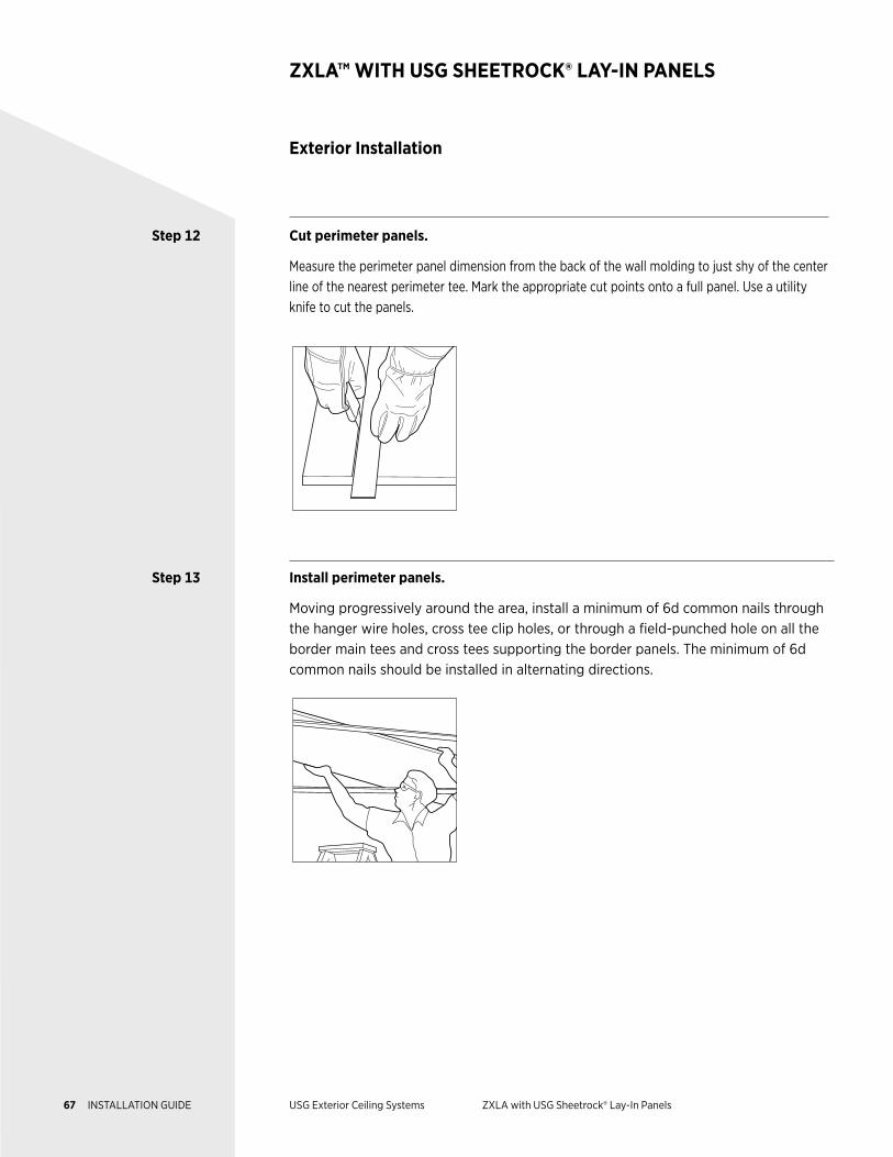
Step 12 Cut perimeter panels.
Measure the perimeter panel dimension from the back of the wall molding to just shy of the center line of the nearest perimeter tee. Mark the appropriate cut points onto a full panel. Use a utility knife to cut the panels.
Step 13 Install perimeter panels.
Moving progressively around the area, install a minimum of 6d common nails through the hanger wire holes, cross tee clip holes, or through a field-punched hole on all the border main tees and cross tees supporting the border panels. The minimum of 6d common nails should be installed in alternating directions.
Exterior Installation
ZXLA™ WITH USG SHEETROCK® LAY-IN PANELS
67 INSTALLATION GUIDE USG Exterior Ceiling Systems ZXLA with USG Sheetrock® Lay-In Panels
Exterior Installation
ZXLA™ WITH USG SHEETROCK® LAY-IN PANELS
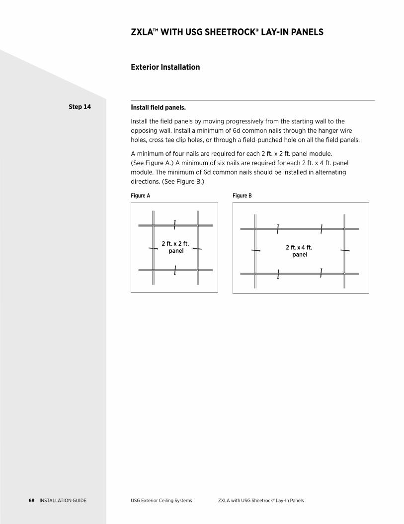
Step 14 Install field panels.
Install the field panels by moving progressively from the starting wall to the opposing wall. Install a minimum of 6d common nails through the hanger wire holes, cross tee clip holes, or through a field-punched hole on all the field panels.
A minimum of four nails are required for each 2 ft. x 2 ft. panel module. (See Figure A.) A minimum of six nails are required for each 2 ft. x 4 ft. panel module. The minimum of 6d common nails should be installed in alternating directions. (See Figure B.)
Figure A Figure B
2 ft. x 2 ft. panel
2 ft.x 4 ft. panel
68 INSTALLATION GUIDE USG Exterior Ceiling Systems ZXLA with USG Sheetrock® Lay-In Panels
DESCRIPTION The USG Drywall Suspension System (DWSS) is a versatile and customizable
framing system that can achieve numerous design aesthetics and is supported
by testing for a variety of installation requirements. It integrates with an array
of components and accessories to meet visual design and installation needs.
NOTES Follow proper safety and industrial hygiene practices while handling and installing all products and systems. Take necessary precautions and wear appropriate personal protective equipment as needed. For product safety information and personal protective equipment recommendations review the safety data sheet. When removing or installing ceiling panels from grid, we recommend wearing a dust mask, cut-resistant gloves, and eye protection. Provide drop cloths to cover and protect furnishings below. When using a ladder or lift, follow the equipment manufacturer’s precautions, instructions, and safety guidelines.
All ceiling products and systems must be installed and maintained in accordance with current USG written instructions and in compliance with ASTM C636, ASTM E580, CISCA, and standard industry practices.
Care must be taken to safeguard products from damage during delivery and while they are stored at the jobsite. The products must always be protected from vibration, chemical fumes, and direct contact with water both before and after installation.
USG DRYWALL SUSPENSION SYSTEM
Exterior Ceiling Applications
Ceiling Grid Framing System
69 INSTALLATION GUIDE USG Exterior Ceiling Systems USG Drywall Suspension System
Components
USG DRYWALL SUSPENSION SYSTEM
Suspension Systems
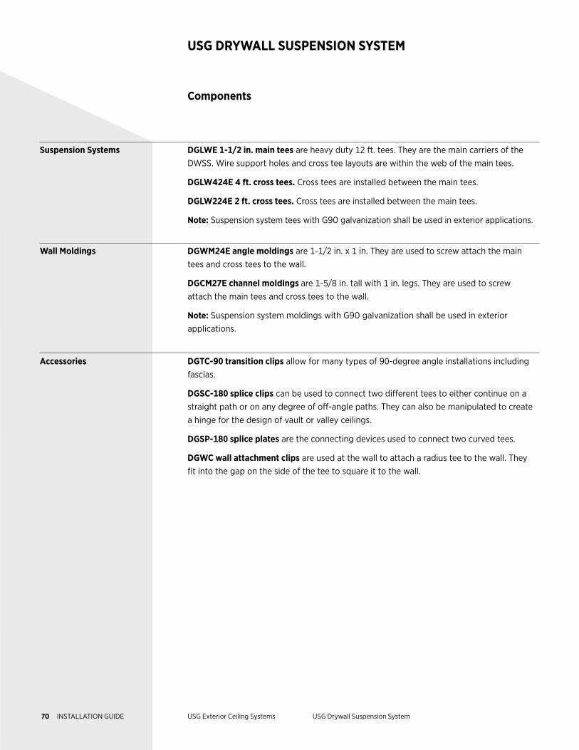
DGLWE 1-1/2 in. main tees are heavy duty 12 ft. tees. They are the main carriers of the DWSS. Wire support holes and cross tee layouts are within the web of the main tees.
DGLW424E 4 ft. cross tees. Cross tees are installed between the main tees.
DGLW224E 2 ft. cross tees. Cross tees are installed between the main tees.
Note: Suspension system tees with G90 galvanization shall be used in exterior applications.
Wall Moldings DGWM24E angle moldings are 1-1/2 in. x 1 in. They are used to screw attach the main tees and cross tees to the wall.
DGCM27E channel moldings are 1-5/8 in. tall with 1 in. legs. They are used to screw attach the main tees and cross tees to the wall.
Note: Suspension system moldings with G90 galvanization shall be used in exterior applications.
Accessories DGTC-90 transition clips allow for many types of 90-degree angle installations including fascias.
DGSC-180 splice clips can be used to connect two different tees to either continue on a straight path or on any degree of off-angle paths. They can also be manipulated to create a hinge for the design of vault or valley ceilings.
DGSP-180 splice plates are the connecting devices used to connect two curved tees.
DGWC wall attachment clips are used at the wall to attach a radius tee to the wall. They fit into the gap on the side of the tee to square it to the wall.
70 INSTALLATION GUIDE USG Exterior Ceiling Systems USG Drywall Suspension System
Components
USG DRYWALL SUSPENSION SYSTEM
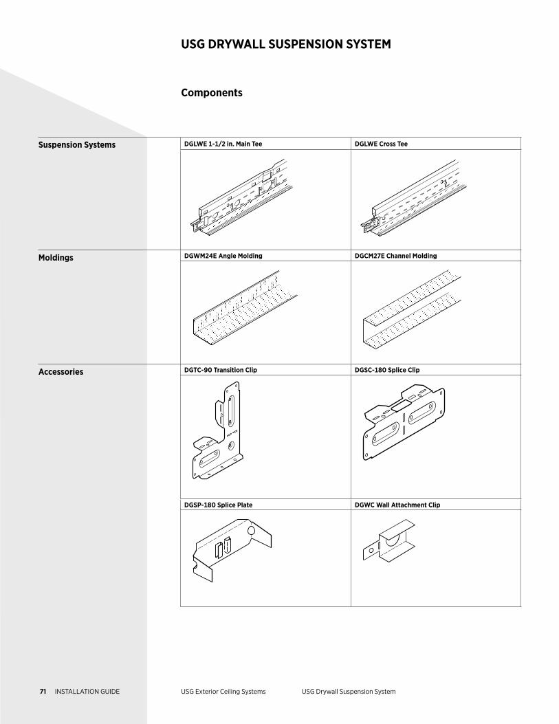
Suspension Systems DGLWE 1-1/2 in. Main Tee DGLWE Cross Tee
Moldings DGWM24E Angle Molding DGCM27E Channel Molding
Accessories DGTC-90 Transition Clip DGSC-180 Splice Clip
DGSP-180 Splice Plate DGWC Wall Attachment Clip
71 INSTALLATION GUIDE USG Exterior Ceiling Systems USG Drywall Suspension System
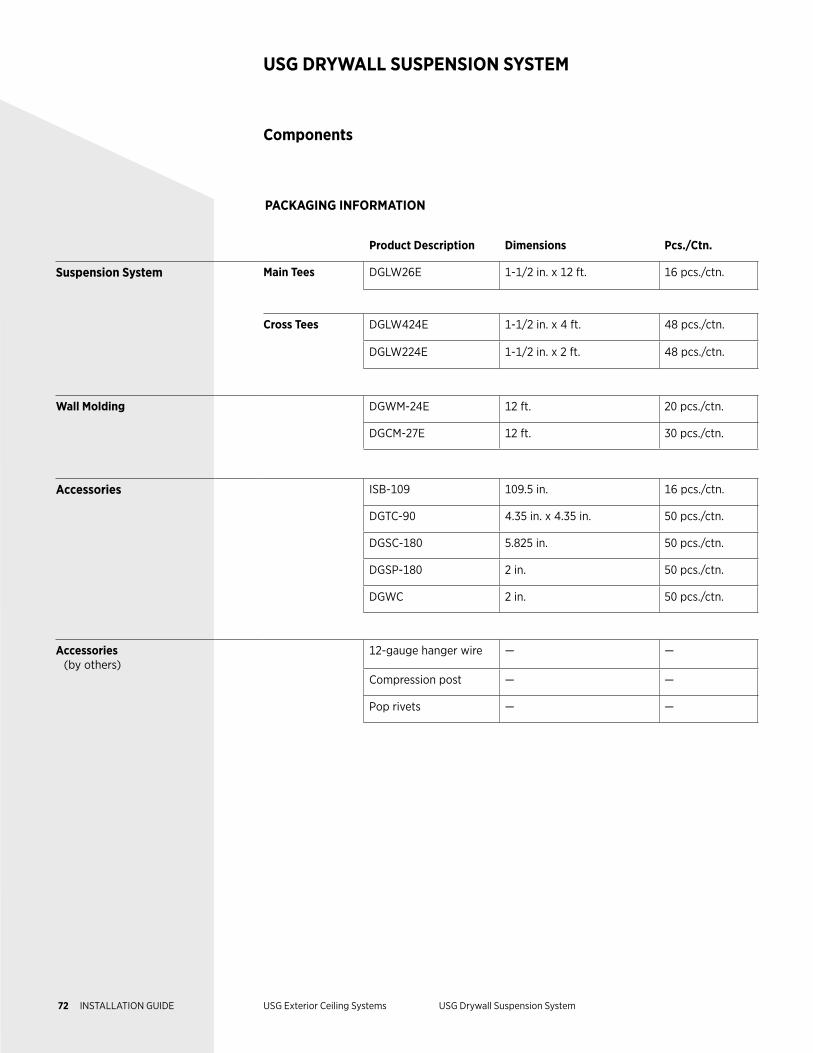
Product Description Dimensions Pcs./Ctn.
Suspension System Main Tees DGLW26E 1-1/2 in. x 12 ft. 16 pcs./ctn.
Cross Tees DGLW424E 1-1/2 in. x 4 ft. 48 pcs./ctn.
DGLW224E 1-1/2 in. x 2 ft. 48 pcs./ctn.
Wall Molding DGWM-24E 12 ft. 20 pcs./ctn.
DGCM-27E 12 ft. 30 pcs./ctn.
Accessories ISB-109 109.5 in. 16 pcs./ctn.
DGTC-90 4.35 in. x 4.35 in. 50 pcs./ctn.
DGSC-180 5.825 in. 50 pcs./ctn.
DGSP-180 2 in. 50 pcs./ctn.
DGWC 2 in. 50 pcs./ctn.
Accessories (by others)
12-gauge hanger wire — —
Compression post — —
Pop rivets — —
Components
USG DRYWALL SUSPENSION SYSTEM
PACKAGING INFORMATION
72 INSTALLATION GUIDE USG Exterior Ceiling Systems USG Drywall Suspension System
Exterior Installation
USG DRYWALL SUSPENSION SYSTEM
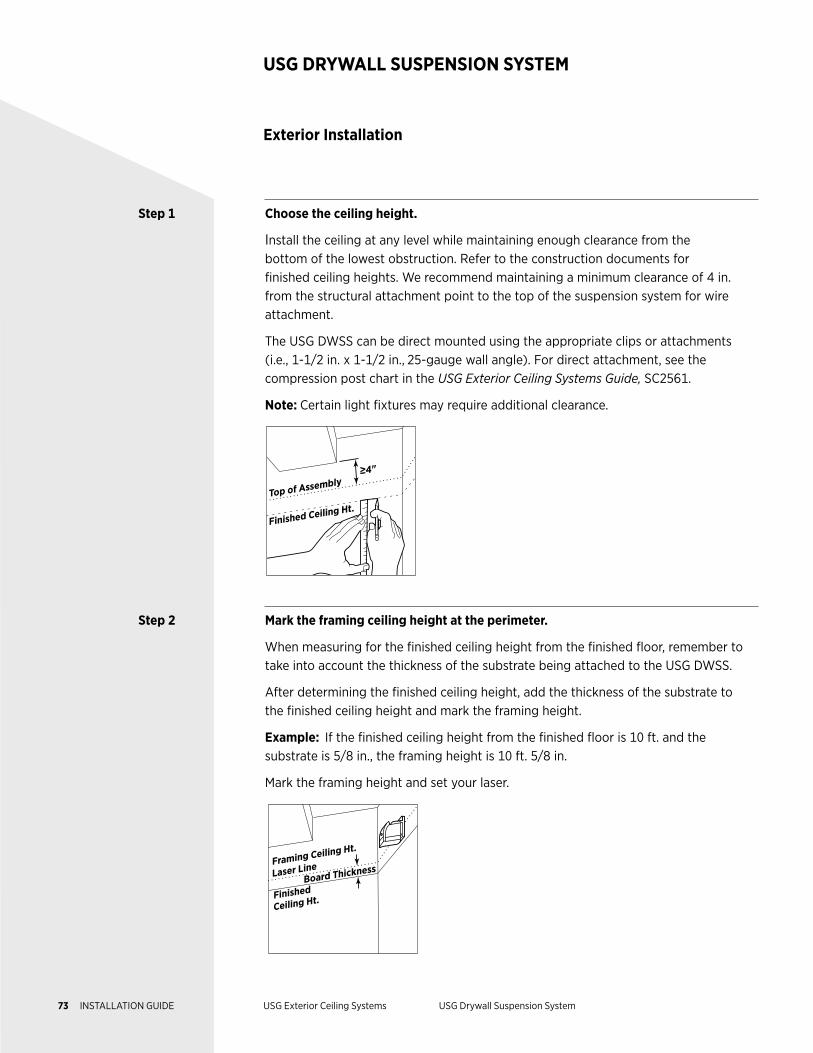
Step 1 Choose the ceiling height.
Install the ceiling at any level while maintaining enough clearance from the bottom of the lowest obstruction. Refer to the construction documents for finished ceiling heights. We recommend maintaining a minimum clearance of 4 in. from the structural attachment point to the top of the suspension system for wire attachment.
The USG DWSS can be direct mounted using the appropriate clips or attachments (i.e., 1-1/2 in. x 1-1/2 in., 25-gauge wall angle). For direct attachment, see the compression post chart in the USG Exterior Ceiling Systems Guide, SC2561.
Note: Certain light fixtures may require additional clearance.
≥4"
Finished Ceiling Ht.Top of Assembly
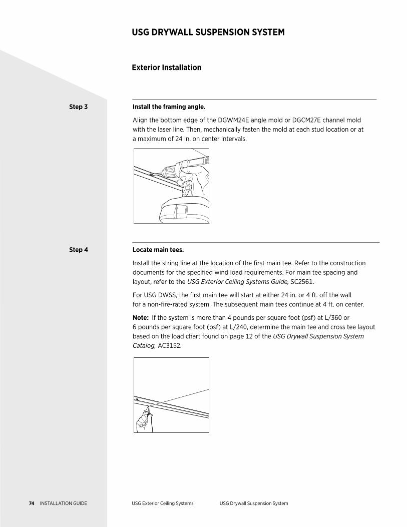
Step 2 Mark the framing ceiling height at the perimeter.
When measuring for the finished ceiling height from the finished floor, remember to take into account the thickness of the substrate being attached to the USG DWSS.
After determining the finished ceiling height, add the thickness of the substrate to the finished ceiling height and mark the framing height.
Example: If the finished ceiling height from the finished floor is 10 ft. and the substrate is 5/8 in., the framing height is 10 ft. 5/8 in.
Mark the framing height and set your laser.
Board Thickness
Finished
Ceiling Ht.
Framing Ceiling Ht.
Laser Line
73 INSTALLATION GUIDE USG Exterior Ceiling Systems USG Drywall Suspension System
Exterior Installation
USG DRYWALL SUSPENSION SYSTEM
Step 3 Install the framing angle.
Align the bottom edge of the DGWM24E angle mold or DGCM27E channel mold with the laser line. Then, mechanically fasten the mold at each stud location or at a maximum of 24 in. on center intervals.
Step 4 Locate main tees.
Install the string line at the location of the first main tee. Refer to the construction documents for the specified wind load requirements. For main tee spacing and layout, refer to the USG Exterior Ceiling Systems Guide, SC2561.
For USG DWSS, the first main tee will start at either 24 in. or 4 ft. off the wall for a non-fire-rated system. The subsequent main tees continue at 4 ft. on center.
Note: If the system is more than 4 pounds per square foot (psf) at L/360 or 6 pounds per square foot (psf) at L/240, determine the main tee and cross tee layout based on the load chart found on page 12 of the USG Drywall Suspension System Catalog, AC3152.
74 INSTALLATION GUIDE USG Exterior Ceiling Systems USG Drywall Suspension System
Step 3 Install the framing angle.
Align the bottom edge of the DGWM24E angle mold or DGCM27E channel mold with the laser line. Then, mechanically fasten the mold at each stud location or at a maximum of 24 in. on center intervals.
Step 4 Locate main tees.
Install the string line at the location of the first main tee. Refer to the construction documents for the specified wind load requirements. For main tee spacing and layout, refer to the USG Exterior Ceiling Systems Guide, SC2561.
For USG DWSS, the first main tee will start at either 24 in. or 4 ft. off the wall for a non-fire-rated system. The subsequent main tees continue at 4 ft. on center.
Note: If the system is more than 4 pounds per square foot (psf) at L/360 or 6 pounds per square foot (psf) at L/240, determine the main tee and cross tee layout based on the load chart found on page 12 of the USG Drywall Suspension System Catalog, AC3152.
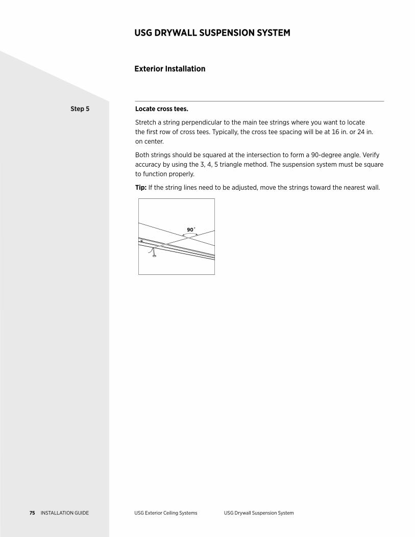
Step 5 Locate cross tees.
Stretch a string perpendicular to the main tee strings where you want to locate the first row of cross tees. Typically, the cross tee spacing will be at 16 in. or 24 in. on center.
Both strings should be squared at the intersection to form a 90-degree angle. Verify accuracy by using the 3, 4, 5 triangle method. The suspension system must be square to function properly.
Tip: If the string lines need to be adjusted, move the strings toward the nearest wall.
90˚
Exterior Installation
USG DRYWALL SUSPENSION SYSTEM
75 INSTALLATION GUIDE USG Exterior Ceiling Systems USG Drywall Suspension System
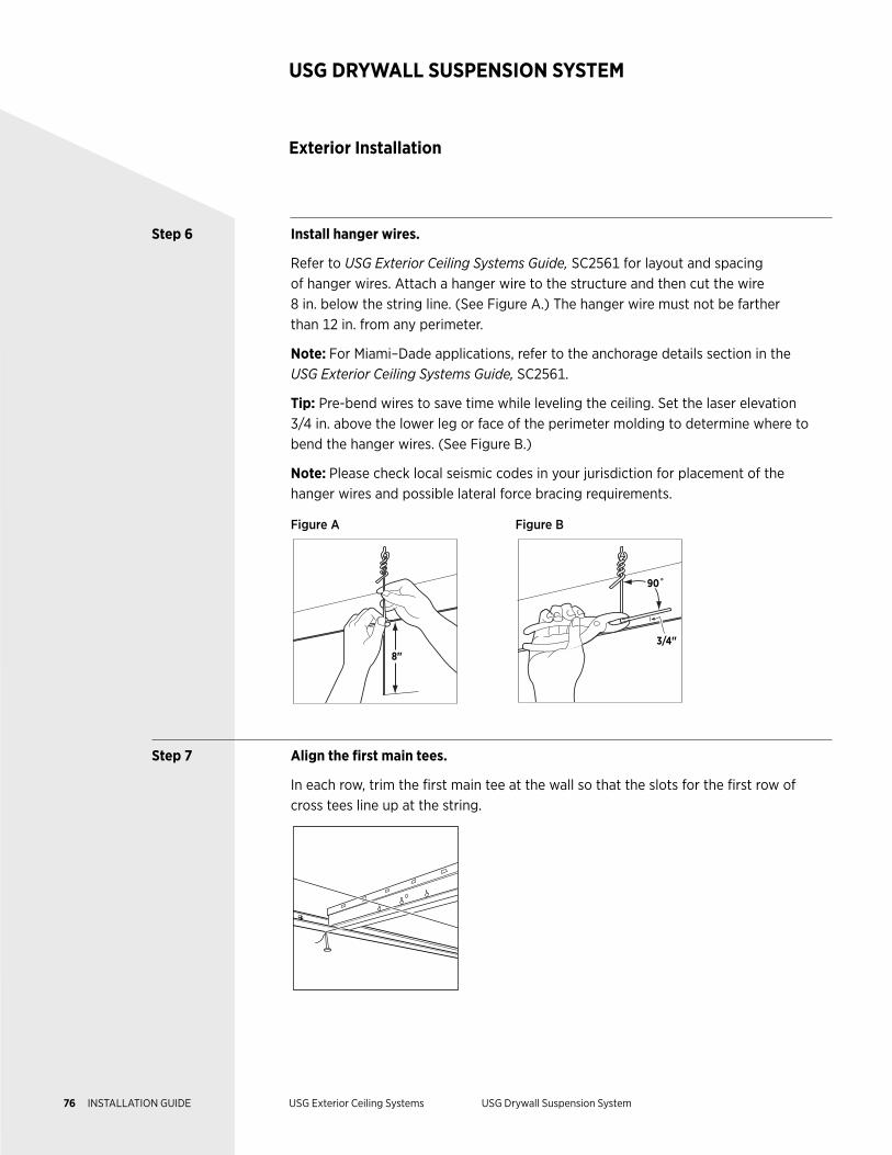
Step 6 Install hanger wires.
Refer to USG Exterior Ceiling Systems Guide, SC2561 for layout and spacing of hanger wires. Attach a hanger wire to the structure and then cut the wire 8 in. below the string line. (See Figure A.) The hanger wire must not be farther than 12 in. from any perimeter.
Note: For Miami–Dade applications, refer to the anchorage details section in the USG Exterior Ceiling Systems Guide, SC2561.
Tip: Pre-bend wires to save time while leveling the ceiling. Set the laser elevation 3/4 in. above the lower leg or face of the perimeter molding to determine where to bend the hanger wires. (See Figure B.)
Note: Please check local seismic codes in your jurisdiction for placement of the hanger wires and possible lateral force bracing requirements.
Figure A Figure B
8"
3/4"
90˚
Step 7 Align the first main tees.
In each row, trim the first main tee at the wall so that the slots for the first row of cross tees line up at the string.
Exterior Installation
USG DRYWALL SUSPENSION SYSTEM
76 INSTALLATION GUIDE USG Exterior Ceiling Systems USG Drywall Suspension System
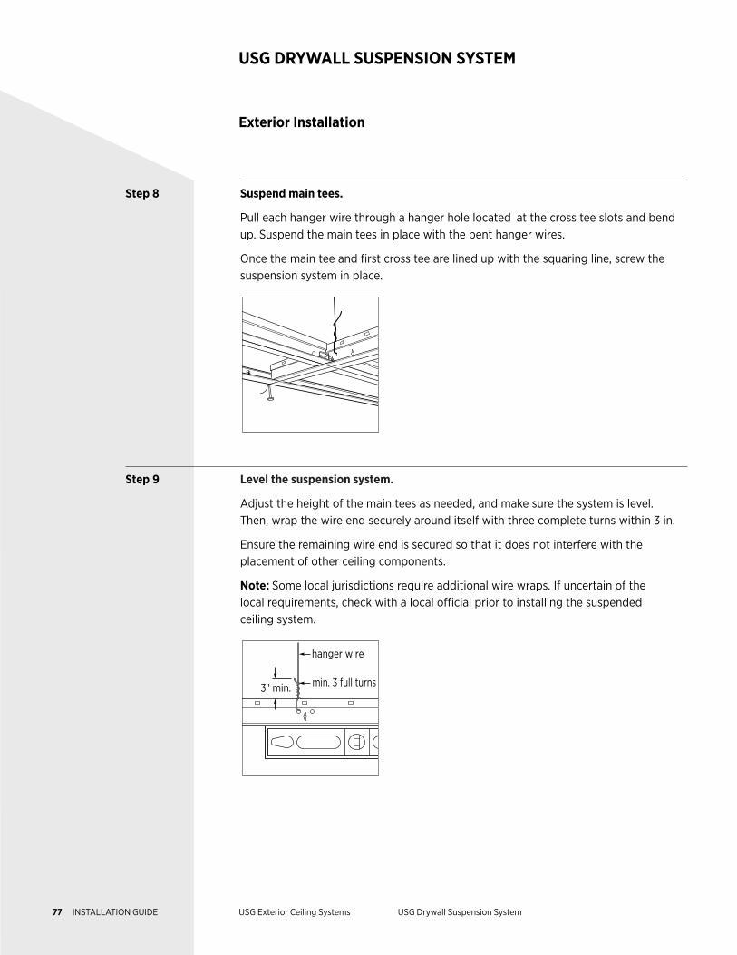
Step 8 Suspend main tees.
Pull each hanger wire through a hanger hole located at the cross tee slots and bend up. Suspend the main tees in place with the bent hanger wires.
Once the main tee and first cross tee are lined up with the squaring line, screw the suspension system in place.
Step 9 Level the suspension system.
Adjust the height of the main tees as needed, and make sure the system is level. Then, wrap the wire end securely around itself with three complete turns within 3 in.
Ensure the remaining wire end is secured so that it does not interfere with the placement of other ceiling components.
Note: Some local jurisdictions require additional wire wraps. If uncertain of the local requirements, check with a local official prior to installing the suspended ceiling system.
hanger wire
3" min. min. 3 full turns
Exterior Installation
USG DRYWALL SUSPENSION SYSTEM
77 INSTALLATION GUIDE USG Exterior Ceiling Systems USG Drywall Suspension System
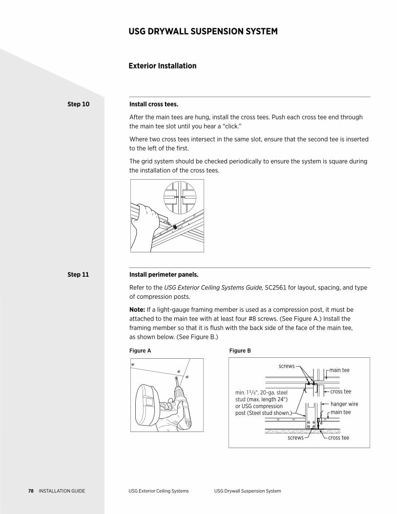
Exterior Installation
USG DRYWALL SUSPENSION SYSTEM
Step 10 Install cross tees.
After the main tees are hung, install the cross tees. Push each cross tee end through the main tee slot until you hear a “click.”
Where two cross tees intersect in the same slot, ensure that the second tee is inserted to the left of the first.
The grid system should be checked periodically to ensure the system is square during the installation of the cross tees.
Step 11 Install perimeter panels.
Refer to the USG Exterior Ceiling Systems Guide, SC2561 for layout, spacing, and type of compression posts.
Note: If a light-gauge framing member is used as a compression post, it must be attached to the main tee with at least four #8 screws. (See Figure A.) Install the framing member so that it is flush with the back side of the face of the main tee, as shown below. (See Figure B.)
Figure A Figure B
screws
screws
cross tee
cross tee
hanger wire
min. 1 5/8", 20-ga. steel stud (max. length 24") or USG compression post (Steel stud shown.) main tee
main tee
78 INSTALLATION GUIDE USG Exterior Ceiling Systems USG Drywall Suspension System
SC3212/9-2017© 2017, USG Corporation or its affiliates. All rights reserved. The trademarks CELEBRATION, FINELINE, PARALINE, SHEETROCK, ZXLA, USG DESIGN STUDIO, CGC DESIGN STUDIO, USG, CGC, IT'S YOUR WORLD BUILD IT, THE USG LOGO and related marks are trademarks of USG Interiors, LLC or a related company..
Manufactured byUSG Interiors, Inc.550 West Adams StreetChicago, IL 60661
PRODUCT INFORMATIONDXFEV Data Sheet AC3304. Celebration Torsion Spring Exterior Accessories IC642. Exterior Ceilings Systems Guide SC2561. See usg.com for the most up-to-date product information.
INSTALLATIONMust be installed in compliance with ASTM C636, ASTM E580, CISCA, and standard industry practices.
CODE COMPLIANCEThe information presented is correct to the best of our knowledge at the date of issuance. Because codes continue to evolve, check with a local official prior to designing and installing a ceiling system. Other restrictions and exemptions may apply.
NOTICEWe shall not be liable for incidental and consequential damages, directly or indirectly sustained, nor for any loss caused by application of these goods not in accordance with current printed instructions or for other than the intended use. Our liability is expressly limited to replacement of defective goods. Any claim shall be deemed waived unless made in writing to us within thirty (30) days from date it was or reasonably should have been discovered.
SAFETY FIRST!Follow good safety and industrial hygiene practices during handling and installation of all products and systems. Take necessary precautions and wear appropriate personal protective equipment as needed. Read safety data sheets and related literature on products before specification and/or installation
WEBSITESusg.comcgcinc.comusgdesignstudio.comcgcdesignstudio.com
NoticeThe information in this document is subject to change without notice. CGC Inc. or USG Corp. assumes no responsibility for any errors that may inadvertently appear in this document.