versions 5.1, 6 - knowledgeowl login...
TRANSCRIPT

SightLogix, Inc. | +1 609.951.0008 | www.sightlogix.com
Configuring Verint Nextiva
Versions 5.1, 6.0
Configuring Third-Party Programs
SightLogix devices are used with two types of third-party programs: VMS programs, which display video, GPS coordinates, and alarm and other information from SightLogix devices, and command and control systems (C2), which are integrated systems for monitoring multiple types of sensors. Currently, SightLogix supports a range of VMS programs and control systems. Additional programs and systems will be supported in the future.
In order for a VMS program to display the video and alarms received from SightLogix devices, the program must be configured properly, both to open communication with devices and to respond appropriately to alarm information. The actual configuration steps differ, depending on the program. However, most programs require the following:
> Setting web authentication between the SightLogix device and the VMS. This includes entering the username and password (the default username is sightlogix or root, and the default password is push2edg). It is recommended that you change both defaults.
It also includes changing to digest web authentication if this more secure web authentication is supported by the individual VMS program. (By default, SightSensors are set up for basic authentication, which is supported by all VMS programs.)
You set both the web username/password and the authentication type from the Web Server dialog (right-click a device icon in the SightMonitor camera tree Configure
Web Server):
> Adding SightSensors as AXIS-211 devices (except when indicated); adding SightTrackers as AXIS 213.

Configuring Verint Nextiva
> Specifying the actions (or events) that occur when an alarm is received. This can include, depending on the program: audio alerts, automatic recording during an alarm, bookmarks inserted into recorded video to signal the start or end of an alarm, etc.
> Testing that alarm information is relayed from a SightLogix device to the VMS program. The Alarm Test option on the Camera (right-click device icon Configure) simulates an alarm.
The following sections provide general guidance on how to configure the VMS programs that have been tested with SightLogix devices. However, for detailed, specific information, see the documentation that came with the particular VMS program.
Verint Nextiva versions 5.1, 6.0
This section describes how to set up the following Verint Nextiva versions. Refer to the preferred section.
• Verint Nextiva 5.1
• Verint Nextiva 6.0
Verint Nextiva 5.1 SightLogix devices are qualified with the following versions of Nextiva.
> Nextiva Master Recorder 5.1
> Nextiva Master 5.1 with Nextiva Recorder(s) 5.1
> Nextiva 5.1 Rollup 4 or higher
> Nextiva Axis Adapter 3651 for Nextiva 5.1 Rollup 4 or higher
> Nextiva 5.1 Alarm and Event Interface Server (5.1.3648)
All instructions from Verint for installing the rollups and adapters have to be followed before adding a SightLogix device.
At the SightMonitor, you need to disable RTCP timeouts. Open the MPEG configuration tab (right-click the device icon Configuration MPEG) and select the checkbox for Disable RTCP timeout.

Configuring Verint Nextiva
1. Add a SightLogix device to the AXIS adapter While in the Control Center, open Global Settings (a), and then Adapters (b). Click the Axis Devices icon (c).
Under Devices, select Camera List (d). You’ll see the button at the far right. Click this button for a list of Axis devices.
In the dialog for Axis devices, click (e) and then enter the IP address (f). Enter the username and password, if necessary. (It’s not necessary to enter the model name.) Click OK (g).
Note: You can configure it so that the device username and password are automatically entered for each new device. To do so, go to the Security tab (h) under the Advanced tab.
2. Add a SightLogix device
From the System Component tab, open the Wizard by clicking the wizard button ( ). Advance through the screens by clicking Next.
When you see the screen shown at right, click the Add button ( ). You’ll be prompted to type the device’s serial number; click search to discover the new device. From the new components column, drag the device you just added to the physical group view. Change the device names if you wish. Click Next. When prompted, add the device as a Logical component by dragging it from the physical column to the Logical column; be sure to drag the device over the Camera line. Click Finish when done. It might take up to a minute to add the device.
By default, devices are configured for MPEG. To change to JPEG, do the following: select the device, and then Video. Change the setting for the video type and click Apply.
3. Add a video and recording profile Video and recording profiles allow you to specify when to record (continuously or only during alarms), and what video settings to use. You can use the default profile or make changes. To access profile settings: Under System Components (a), select Recording and Archiving (b) and then Recording Profiles (c). This opens the tab pages shown here. Make changes to the default profile or click Add to create a new one.
When finished making changes, click Apply at the lower right (not shown here).
a
b
c
f
e
d
g
a
b
c
h

Configuring Verint Nextiva
4. Assign an IntelliStream source ID for events First enter the Nextiva server’s IP and port information at the SightMonitor so the SightLogix device knows where to send alarm information. Go to the SightMonitor’s Camera dialog for the device (right-click the device icon Configure Camera) and, for Motion On, enter the Verint system IP address and port number using the following syntax: IP-address:port-number.
At Nextiva, enter a unique number for the video source as follows: Under System Components (a), select IntelliStream (b), enter a unique number for the device you just added (c). Click Apply.
5. Create a configuration file for the alarm interface Create a configuration file similar to the one shown on the next page and copy to C:\Verint\AlarmInterface\Config.xml. Supply the relevant information for your Verint server and each of the SightLogix devices.
In the following sample file, the IP address of the server running the Alarm Interface is 192.168.1.10. The SightLogix devices are configured with the Alarm Server Motion On server = 192.168.1.10:8081.
Each SightLogix device requires a rule that includes the serial number of the device, the unique ID of the event, and the device ID, which you assigned in step 3. The sample file shows three devices (serial numbers 000000123, 000000150, and 000000247).
a
b
c

Configuring Verint Nextiva
Once you create the file, stop and restart the Nextiva services as follows: Right-click the Verint icon
( ) at the lower right: select Stop from the menu that appears. Restart by again opening this menu.
Then stop and restart the Nextiva Alarm Interface service from Windows Services as follows: navigate Start Settings Control Panel Admin Tools Services. This reads the newly modified Config.xml file permitting alarm recognition and passes on the alarm to Nextiva Review for reporting.
<config>
<!-- SightLogix configuration file -->
<!-- Log levels are: ERROR WARN INFO DEBUG -->
<Logging filename="Logging/NextivaAlarmServer.log" level="ERROR"
daysToLive="31"/>
<site name="DEMOHP Nextiva" url="tcp://192.168.1.10:5005"
username="Administrator" password="cctvware"/>
<tcpPort name="tcp_On" port="8081"/>
<listener input="tcp_On" separator=":On" response="OK ">
<rule>
<match contains="000000123"/>
<event id="123" argument="SN:000000123">
<camera number="10"/>
</event>
</rule>
Insert IP address of your Verint server, followed by the port number. Enter a username and password for your site.
Set log level here. Set daysToLive for the number of days to keep log files.
Enter a name and port number for the port on which SightLogix devices listen and report events. The port used cannot conflict with other ports and must get through a firewall. A good choice is usually 8081.

Configuring Verint Nextiva
<rule>
<match contains="000000150"/>
<event id="150" argument="SN:000000150">
<camera number="11"/>
</event>
</rule>
<rule>
<match contains="000000160"/>
<event id="160" argument="SN:000000160">
<camera number="12"/>
</event>
</rule>
<rule>
<match contains="000000247"/>
<event id="247" argument="SN:000000247">
<camera number="13"/>
</event>
</rule>
</listener>
</config>
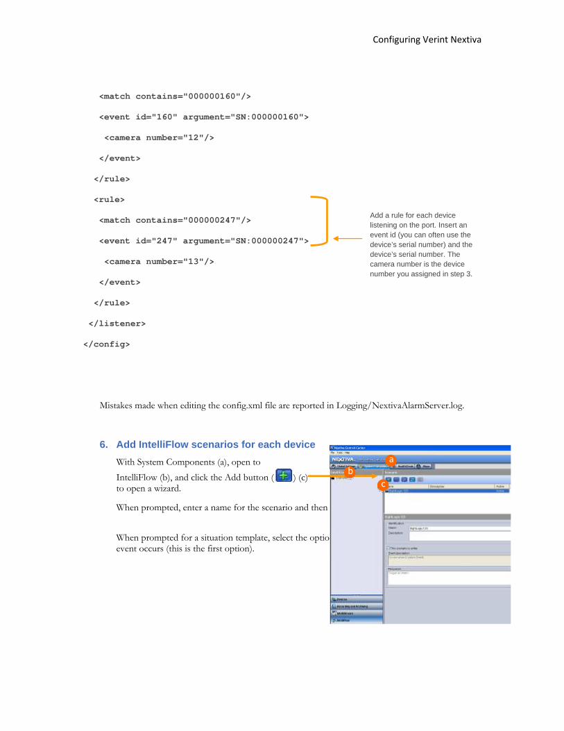
Mistakes made when editing the config.xml file are reported in Logging/NextivaAlarmServer.log.
Add a rule for each device listening on the port. Insert an event id (you can often use the device’s serial number) and the device’s serial number. The camera number is the device number you assigned in step 3.

Configuring Verint Nextiva
1. Add IntelliFlow scenarios for each device With System Components (a), open to IntelliFlow (b), and click the Add button ( ) to open a wizard. When prompted, enter a name for the scenario. Click Next. When prompted for a situation template, select the option for triggering a response when an event occurs (this is the first option).
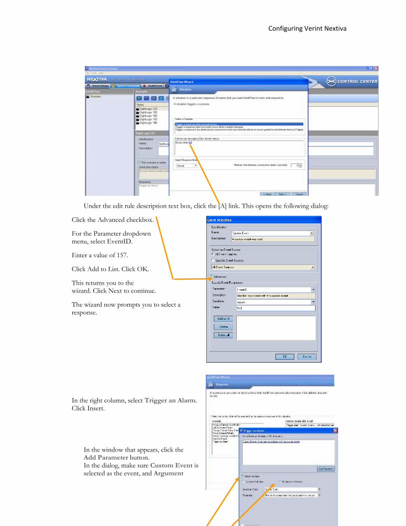
Under the edit rule description text box, click the [A] link. This opens the following dialog:
Click the Advanced checkbox.
For the Parameter dropdown menu, select EventID.
Enter a value of 157.
Click Add to List. Click OK.
This returns you to the wizard. Click Next to continue.
The wizard now prompts you to select a response.
a
b c

Configuring Verint Nextiva
In the right column, select Trigger an Alarm. Click Insert.
In the window that appears, click the Add Parameter button. In the dialog, make sure Custom Event is selected as the event, and Argument associated with the custom event is selected as the parameter. Click OK.
Select the Attach cameras checkbox; enable the Parameter Reference radio button.
Click OK. Click Next.
Next you’re prompted for the coverage. Select the coverage you want and click Insert. Click Next. Then Finish.
At this point you can view video from the SightLogix device. Open the Nextiva Review; from under All Cameras, select a SightLogix device and drag to a file.

Configuring Verint Nextiva
Verint Nextiva version 6.0 SightLogix devices are qualified with the following versions of Nextiva.
> Nextiva Master Recorder 6.0
> Nextiva Master 6.0 with Nextiva Recorder(s) 6.0
> Nextiva 6.0 Rollup 4 or higher
> Nextiva Axis Adapter 6.0_008 for Nextiva 6.0 Rollup 4 or higher
> Nextiva 6.0 Alarm and Event Interface Server (6.0.137)
All instructions from Verint for installing the rollups and adapters have to be followed before adding a Sightlogix device.
At the SightMonitor, you need to disable RTCP timeouts. Open the MPEG configuration tab (right-click the device icon Configuration MPEG) and select the checkbox for Disable RTCP timeout.
1. Add a SightLogix device to the AXIS adapter While in the Control Center, open Global Settings (a), then Adapters (b). Click the Axis Devices icon (c).
Under Devices, select Camera List (d). You’ll see the button at the far right. Click this button for a list of Axis devices.
In the dialog for Axis devices, click (e) and then enter the IP address (f). Enter the username and password, if necessary. (It’s not necessary to enter the model name.) Click OK (g).
Note: You can configure it so that the device username and password are automatically entered for each new device. To do so, go to the Security tab (h) under the Advanced tab.
a
b
c
f
e
d
g h

Configuring Verint Nextiva
2. Add a SightLogix device From the System Component tab, open the Wizard by clicking the wizard button ( ). Advance through the screens by clicking Next.
When you see the screen shown at right, click the Add button ( ). You’ll be prompted to type the device’s serial number; click search to discover the new device. From the new components column, drag the device you just added to the physical group view. Change the device names if you wish. Click Next. When prompted, add the device as a Logical component by dragging it from the physical column to the Logical column; be sure to drag the device over the Camera line. Click Finish when done. It might take up to a minute to add the device.
By default, devices are configured for MPEG. To change to JPEG, do the following: select the device, and then select Video. Change the setting for the video type and then click Apply.
3. Add a video and recording profile Video and recording profiles allow you to specify when to record (continuously or only during alarms), and what video settings to use. You can use the default profile or make changes. To access profile settings: Under System Components (a), select Recording and Archiving (b) and then Recording Profiles (c). This opens the tab pages shown here. Make changes to the default profile or click Add to create a new one.
When finished making changes, click Apply at the lower right (not shown here).
4. Assign an IntelliStream source ID for events First enter the Nextiva server’s IP and port information at the SightMonitor so the SightLogix device knows where to send alarm information. Go to the SightMonitor’s Camera dialog for the device (right-click the device icon Configure Camera) and, for Motion On, enter the Verint system IP address and port number using the following syntax: IP-address:port-number.
At Nextiva, enter a unique number for the video source as follows: Under System Components (a), select IntelliStream (b), enter a unique number for the device you just added (c). Click Apply.
a
b
c

Configuring Verint Nextiva
5. Create a configuration file for the alarm interface Create a configuration file similar to the one shown on the next page and copy to C:\Verint\AlarmInterface\Config.xml. Supply the relevant information for your Verint server and each of the SightLogix devices.
In the following sample file, the IP address of the server running the Alarm Interface is 192.168.1.10. The SightLogix devices are configured with the Alarm Server Motion On server = 192.168.1.10:8081.
Each SightLogix device requires a rule that includes the serial number of the device, the unique ID of the event, and the device ID, which you assigned in step 3. The sample file shows three devices (serial numbers 000000123, 000000150, and 000000247).
Once you create the file, stop and restart the Nextiva services as follows: Right-click the Verint icon
( ) at the lower right: select Stop from the menu that appears. Restart by again opening this menu.
Then stop and restart the Nextiva Alarm Interface service from Windows Services as follows: navigate Start Settings Control Panel Admin Tools Services. This reads the newly modified
a
b
c

Configuring Verint Nextiva
Config.xml file permitting alarm recognition and passes on the alarm to Nextiva Review for reporting.
<config>
<!-- SightLogix configuration file -->
<!-- Log levels are: ERROR WARN INFO DEBUG -->
<Logging filename="Logging/NextivaAlarmServer.log" level="ERROR"
daysToLive="31"/>
<site name="DEMOHP Nextiva" url="tcp://192.168.1.10:5005"
username="Administrator" password="cctvware"/>
<tcpPort name="tcp_On" port="8081"/>
<listener input="tcp_On" separator=":On" response="OK ">
<rule>
<match contains="000000123"/>
<event id="123" argument="SN:000000123">
<camera number="10"/>
</event>
</rule>
<rule>
<match contains="000000150"/>
<event id="150" argument="SN:000000150">
<camera number="11"/>
</event>
</rule>
<rule>
Insert IP address of your Verint server, followed by the port number. Enter a username and password for your site.
Set log level here. Set daysToLive for the number of days to keep log files.
Enter a name and port number for the port on which SightLogix devices listen and report events. The port used cannot conflict with other ports and must get through a firewall. A good choice is usually 8081.
Configuring Verint Nextiva
<match contains="000000160"/>
<event id="160" argument="SN:000000160">
<camera number="12"/>
</event>
</rule>
<rule>
<match contains="000000247"/>
<event id="247" argument="SN:000000247">
<camera number="13"/>
</event>
</rule>
</listener>
</config>
Mistakes made when editing the config.xml file are reported in Logging/NextivaAlarmServer.log.
6. Add IntelliFlow scenarios for each device With System Components (a), open to IntelliFlow (b), and click the Add button ( ) (c) to open a wizard.
When prompted, enter a name for the scenario and then click Next.
When prompted for a situation template, select the option for triggering a response when an event occurs (this is the first option).
Add a rule for each device listening on the port. Insert an event id (you can often use the device’s serial number) and the device’s serial number. The camera number is the device number you assigned in step 3.
a
c b
Configuring Verint Nextiva
Under the edit rule description text box, click the [A] link. This opens the following dialog:
Click the Advanced checkbox.
For the Parameter dropdown menu, select EventID.
Enter a value of 157.
Click Add to List. Click OK.
This returns you to the wizard. Click Next to continue.
The wizard now prompts you to select a response.
In the right column, select Trigger an Alarm. Click Insert.
In the window that appears, click the Add Parameter button. In the dialog, make sure Custom Event is selected as the event, and Argument

Configuring Verint Nextiva
associated with the custom event is selected as the parameter. Click OK.
Select the Attach cameras checkbox; enable the Parameter Reference radio button.
Click OK. Click Next.
Next you’re prompted for the coverage. Select the coverage you want and click Insert. Click Next and then click Finish.
At this point you can view video from the SightLogix device. Open the Nextiva Review; from under All Cameras, select a SightLogix device and drag to a pane.

Configuring Verint Nextiva
SightLogix, Inc. | +1 609.951.0008 | www.sightlogix.com

Configuring Verint Nextiva
SightLogix, Inc. | +1 609.951.0008 | www.sightlogix.com
Copyright © 2011 SightLogix. All rights reserved. www.sightlogix.com SightLogix, SightSensors, and SightTrackers are trademarks of SightLogix, Inc. DiBos and AutoDome are registered trademarks of Bosch Security Systems, inc. DVTel is a registered trademark of DVTel, Inc. Genetec is a registered trademark and Omnicast is a trademark of Genetec Inc. GOOGLE is a trademark of Google Inc. Lenel and OnGuard are registered trademarks of Lenel Systems International, Inc. NetDVMS is a registered trademark of On-Net Surveillance Systems, Inc. NICE is a trademark of NICE Systems Ltd. Pelco is a trademark of Pelco. Proximex Surveillint™ is a trademark of Proximex Corporation. Symmetry is a registered trademark of Group 4 Technology Ltd. Verint is a registered trademark of Verint Systems Inc. XProtect is a registered trademark of Milestone Systems A/S. All other trademarks are the property of their respective owners. SightLogix is a licensee of the GNU General Public License (GPL). You can request a copy of the GPL-licensed source code used in this product from a SightLogix sales office. No part of this document may be reproduced or transmitted in any form or by any means, electronic or mechanical, for any purpose, without the express written permission of SightLogix.
The information in this document is distributed on an “As is” basis and without warranty. While every precaution has been taken in the preparation of this document, SightLogix assumes no responsibility for errors or omissions or for any damages resulting from the use of the information contained herein.