wear behaviour of advanced multilayer coating pvd- tialn ... · wear behaviour of advanced...
TRANSCRIPT
WEAR BEHAVIOUR OF ADVANCED MULTILAYER COATING PVD-
TiAlN IN DRY MACHINING OF AISI D2 HARDENED STEEL
NOR AIN BT JAMIL HOSNI
A thesis submitted in
fulfillment of the requirement for the award of the
Degree of Master of Mechanical and Manufacturing Engineering
Faculty of Mechanical and Manufacturing Engineering
Universiti Tun Hussein Onn Malaysia
NOVEMBER 2013
vii
ABSTRACT
Machining hardened steel is currently receiving increasing attention as a prospective
alternative to the grinding and electrical machining (EDM) which mostly accepted as
traditional methods of machining materials with hardness (>45 HRC). The reason is
that it offers a comparable surface finish, shorter cycle time, fewer process steps,
lower production cost and higher flexibility. In order to demonstrate its advances, it
is important for a critical hard machining processes enable to run in optimal
conditions based on specified objectives and practical constraints. This study was
conducted to investigate the life and wear mechanisms of the tool, machined surface
integrity such as roughness, microhardness beneath the surface and white layer in
end milling of AISI D2 hardened steel (58-62 HRC) in dry machining condition.
Sandvik PVD-TiAlN coated carbide cutting tool was used on a vertical machining
centre (VMC). The cutting conditions including cutting speed (Vc): 80-120 m/min,
radial depth of cut (ae): 3-5 mm and depth of cut (ap) is kept constant at 0.5 mm.
From the results, it was found that the highest acceptable value of tool life and
volume of material removal was obtained at the lowest radial depth of cut of 3 mm
and the lowest cutting speed of 80 m/min. This indicates that this value of radial
depth of cut and cutting speed is more suitable for machining hardened steel
materials. The machined surface experienced microstructure alteration and increment
in microhardness on the top white layer of the machined surface. Severe
microstructure alteration was observed when the tool became dull. In addition,
surface roughness values obtained were within the limit (<4 µm) specified by ISO
standard for machining. Thus, the investigation on relationship of tool wear
performance and surface integrity in machining AISI D2 hardened steel using coated
carbide tool will lead to the development of optimum range of cutting parameters
which promoting maximum productivity, maximum tool life and acceptable surface
integrity of the workpiece. Hence, a good understanding of the relationship between
tool wear performance and surface integrity can be used as the basis of future
development of tooling and workpiece respectively. Finally, the potential of cutting
performances of coated carbide insert in machining AISI D2 hardened steel could be
revealed and have evidences to replace expensive cutting tools such as
Polycrystalline Cubic Boron Nitride (PCBN) which its price 4-5 times higher than
coated carbide insert.
viii
ABSTRAK
Pemesinan keluli keras kini mendapat perhatian sebagai alternatif kepada proses
mencanai dan pemesinan elektrik (EDM) yang kebanyakannya diterima sebagai
kaedah tradisional bahan pemesinan dengan kekerasan (>45 HRC). Ini kerana ia
mempunyai kemasan permukaan, kitaran masa yang pendek,langkah memprosesan
yang kurang, kos pengeluaran yang rendah dan fleksibiliti yang tinggi. Dalam
mencapai kemajuan,proses kritikal pemesinan keras dalam keadaan yang optimum
sangat penting untuk mencapai objektif tertentu dan mengelakkan kekangan
praktikal. Kajian dijalankan untuk menyiasat jangka hayat dan mekanisme alat,
permukaan integriti, kekerasan di bawah permukaan dan lapisan putih AISI keluli
keras D2 (58-62 HRC) dalam keadaan pemesinan kering. Sandvik PVD-TiAlN
bersalut mata alat karbida telah digunakan di pusat pemesinan menegak. Parameter
pemotongan yang digunakan termasuk kelajuan pemotongan: 80-120 m / min,
kedalaman pemotongan: 3-5 mm dan kedalaman pemotonganadalah malar pada 0.5
mm. Keputusan diperolehi nilai jangka hayat tertinggi alat dan jumlah pembuangan
bahan dikedalaman pemotongan paling rendah 3 mm dan kelajuan pemotongan yang
rendah 80 m/min. Ini menunjukkan bahawa nilai kedalaman pemotongan dan
kelajuan pemotongan ini adalah lebih sesuai untuk pemesinan bahan keluli keras.
Permukaan yang dimesin akan mengalami perubahan mikrostruktur dankenaikan
kekerasan pada lapisan atas putih permukaan yang dimesin. Perubahan mikrostruktur
yang teruk berlakuapabila alat menjadi haus. Disamping itu, nilai kekasaran
permukaan yang diperolehi adalah dalam had (<4μm) yang ditentukan oleh ISO
untuk permesinan. Oleh itu, hubungan prestasi memakai alat danpermukaan integriti
pemesinan keluli keras AISI D2 menggunakan alat karbida bersalut akan membawa
kepada pembangunan pelbagai optimum memotong parameter yang menggalakkan
produktiviti maksimum, memaksimumkan hayat alat danpermukaan integriti bahan
kerja. Oleh itu, pemahaman yang baik mengenai hubungan antara prestasi memakai
alat dan permukaan integriti boleh digunakan sebagai asas pembangunan masa depan
peralatan. Akhirnya, potensi memotong persembahan mata alat karbida bersalut
dalam pemesinan keluli keras AISI D2 boleh mendedahkan dan mempunyai bukti-
bukti untuk menggantikan alat pemotong mahal seperti Polycrystalline Cubic Boron
NitridePCBN yang harganya 4-5 kali lebih tinggi daripada mata alat karbida bersalut.
ix
CONTENTS
TITLE i
DECLARATION iv
DEDICATION v
ACKNOWLEDGEMENT vi
ABSTRACT vii
CONTENTS ix
LIST OF FIGURES xiii
LIST OF TABLES xvii
LIST OF ABBREVIATIONS xix
CHAPTER I INTRODUCTION 1
1.1 Recent trends in manufacturing by machining 1
1.1.1 Machinability and surface integrity in machining 4
1.2 Problem Statement 5
1.3 Purpose of Study 7
1.4 Significances of Study 8
1.5 Scopes of Study 8
1.6 Expected Study 10
CHAPTER 2 MACHINABILITY AND SURFACE INTEGRITY 11
2.1 Tool Wear 11
2.1.1 Tool Wear Types 12
2.1.2 Tool Wear Evolution 17
2.1.3 Mechanism of tool wear 19
x
2.1.4 Tool life 20
2.2 Surface integrity 22
2.2.1 Surface topography 23
2.2.2 Surface metallurgy 24
2.3 Coated Carbide Tool 27
2.3.1 Characteristics and uses of tool coating 29
2.3.2 Coating characteristics 29
2.3.3 Commonly used coating 31
2.3.4 The sucessful application of coating 33
CHAPTER 3 LITERATURE REVIEW 34
3.1 Tool life and tool wear performance in machining AISI D2
hardened steel 34
3.2 Surface integrity in machining AISI D2 hardened steel 38
3.3 Coating Characterization of PVD-TiAlN coated carbide tool 41
3.4 Summary 44
CHAPTER 4 METHODOLOGY 47
4.1 High speed milling under the dry cutting 49
4.2 Experimental Design and variables 49
4.3 Research procedure 52
4.3.1 Workpiece preparation 53
4.3.2 Cutting tool preparation 57
4.4 Experimental setup 60
4.5 Equipment and Instrumentation 61
xi
4.5.1 Machine milling preparation 61
4.5.2 Measuring Instruments 63
4.6 Sample preparation of machined workpiece analysis 68
4.6.1 Sectioning 70
4.6.2 Mounting of specimens (compression mounting) 71
4.6.3 Grinding 73
4.6.4 Polishing 74
4.6.5 Etching 75
4.7 Tool wear measurement 76
4.8 Microhardness measurement 77
4.9 Specimen preparation for coating analysis 78
CHAPTER 5 RESULT AND DISCUSSION 80
5.1 Tool life performance 81
5.1.1 The effects of cutting speed on tool wear, tool life
performance and volume material removal 94
5.1.2 The effects of radial depth of cut on tool wear, tool
life performance and volume material removal 103
5.2 Surface Integrity 111
5.2.1 Surface roughness of machined surface 111
5.2.2 Tool wear propagation and surface roughness 114
5.2.3 Surface defects of machined surface 122
5.2.4 Microstructural alterations 125
5.2.5 White layer formation 128
5.2.6 Work hardening layer formation and microhardness 130
5.2.7 Subsurface deformation of machined workpiece 138
xii
5.3 Coating Characteristics 140
5.3.1 Hardness 144
5.3.2 Oxidation resistance measurement using
thermogravimetric analysis (TGA) 145
5.3.3 Discussion on coating characterization 148
CHAPTER 6 CONCLUSION AND RECOMMENDATION 149
6.1 Conclusion 149
6.2 Contribution of this project 153
6.3 Recommendations 154
REFERENCES 156
RELATED PUBLICATION 164
APPENDICES 166
xiii
LIST OF FIGURES
1.1 Problems in hard machining (Jasni., 2012) 6
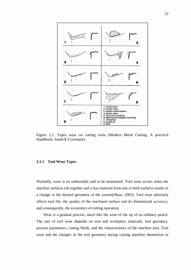
2.1 Types wear on cutting tools (Modern Metal Cutting, A practical
Handbook, Sandvik Coromant). 12
2.2 Wear of endmilling tools, from ISO 8688-2 15
2.3 Chipping: (a) CH1, and (b) CH2 16
2.4 Two wear types when machining the material 16
2.5 Wear curves: (a) normal wear curve, (b) evolution of flank wear
land VBB as a function of cutting time for different cutting
speeds (Davim, 2008). 18
2.6 Evolution of the flank wear land VBB as a function of cutting
time for different cutting speeds (Abburi & Dixit, 2006). 19
2.7 The six groups of key factors that define the surface integrity of
a finished material (ASM, 1994) 23
2.8 Schematic section through a machined surface (Griffiths, 2001) 25
2.9 SEM micrograph of subsurface of machined workpiece 26
2.10 Tribologically important properties in different zones of the
coated surface (Holmberg et al., 2009) 28
4.1 Overall study Methodologies and Factors Influence the
experiments 52
4.2 Two categories of machining characteristics 50
4.3 Experimental process procedure 52
4.4 The metallurgical structure of the original workpiece material 53
4.5 EDAX analysis of AISI D2 hardened steel 54
4.6 PVD-TiAlN Sandvik Coromant Insert 57
4.7 Cross-section of PVD-TiAlN coated tools, revealed in scanning
electron microscope, showing the layer thickness of coating
approximately 4µm. 58
4.8 Dimensional and geometry of PVD-TiAlN coated carbide tool
(Sandvik Coromant CoroMill 390 catalogue) 58
4.9 Specimen test preparation (Jasni, 2012) 60
4.10 CNC Milling Machine (Mazak Variaxis 500-5x) 62
xiv
4.11 Mitutoyo Surftest SJ-400 surface roughness tester 64
4.12 Tool Maker Microscope Nikon MM-60 65
4.13 Scanning Electron Microscope (Jeol-JSM 6380 L.V) 66
4.14 Vickers Tester 68
4.15 Subsurface region of machined surface ( Jasni et al., 2012) 69
4.16 Specimen preparation for subsurface of machined workpiece
analysis 70
4.17 Work piece machined. 71
4.18 Abrasive cut-off machine 71
4.19 Specimen after compression mounting 72
4.20 Buehler Auto Mounting Press Machine 72
4.21 Buehler Roll Grinder 73
4.22 Manual or ―hand‖ polishing machine 74
4.23 Standard for etchants 75
4.24 Schematic diagram of experimental set-up to measure tool wear. 76
4.25 Microhardness measurement beneath the machined surface 78
4.26 Specimen preparation for subsurface of coating analysis 79
5.1 Length of cut (LOC) achieved when machining AISI D2
hardened steel using PVD-TiAlN coated carbide insert 82
5.2 Tool life curves of PVD-TiAlN coated tools at various
conditions 83
5.3 Volume Material Removal, VMR and tool life at different
cutting speeds and radial depth of cuts 84
5.4 Percentage difference of tool life when increasing radial depth
of cut at cutting speed of 80 m/min. 85
5.5 Percentage difference of tool life when increasing radial depth
of cut at cutting speed of 100 m/min. 86
5.6 Percentage difference of tool life when increasing radial depth
of cut at cutting speed of 120 m/min. 86
5.7 Percentage difference of tool life when increasing cutting speed
at radial depth of cut of 3 mm 87
5.8 Percentage difference of tool life when increasing cutting speed
at radial depth of cut of 4 mm 88
xv
5.9 Percentage difference of tool life when increasing cutting speed
at radial depth of cut of 5 mm 88
5.10 Percentage difference of VMR when increasing radial depth of
cut at cutting speed of 80 m/min. 89
5.11 Percentage difference of VMR when increasing radial depth of
cut at cutting speed of 100 m/min. 89
5.12 Percentage difference of VMR when increasing radial depth of
cut at cutting speed of 120 m/min. 90
5.13 Percentage difference of VMR when increasing cutting speed at
radial depth of cut of 3 mm 91
5.14 Percentage difference of VMR when increasing cutting speed at
radial depth of cut of 4 mm 91
5.15 Percentage difference of VMR when increasing cutting speed at
radial depth of cut of 5 mm 92
5.16 Volume material removal and tool life versus cutting speed at
radial depth of cut of 5 mm 94
5.17 Volume material removal and tool life versus cutting speed at
radial depth of cut of 4 mm 95
5.18 Volume material removal and tool life versus cutting speed at
radial depth of cut of 3 mm 96
5.19 Wear on the flank faces tool for various cutting speeds at radial
depth of cut, ae=5 mm 97
5.20 EDAX analysis on the flank face at Vc=80 m/min,ae=5 mm 99
5.21 EDAX analysis on the flank face at Vc=100 m/min,ae=5 mm 99
5.22 EDAX analysis on the flank face at Vc=120 m/min,ae=5 mm 100
5.23 SEM micrographs at different cutting speed kept constant of
radial depth of cut, 5 mm 101
5.24 Volume material removal and tool life for each radial depth of
cut at cutting speed, Vc=80 m/min 103
5.25 Volume material removal and tool life for each radial depth of
cut at cutting speed, Vc=100 m/min 104
5.26 Volume material removal and tool life for each radial depth of
cut at cutting speed, Vc=120 m/min 105
xvi
5.27 Wear on the flank faces for various radial depth of cut at Vc
=120 m/min 107
5.28 EDAX analysis on the flank face at Vc=120 m/min, ae=3 mm 108
5.29 EDAX analysis on the flank face at Vc=120 m/min, ae=4 mm 109
5.30 EDAX analysis on the flank face at Vc=120 m/min, ae=5 mm 109
5.31 SEM analysis at different radial depth of cuts and kept constant
of Vc=120 m/min 110
5.32 Surface roughness trends 112
5.33 Influence radial depth of cut on surface roughness 113
5.34 Tool wear progression 114
5.35 Area wear on the cutting edge at (a) 80 m/min; (b) and 120
m/min 115
5.36 Graph progressive of flank wear (mm) versus length of cuts
(mm) when milling AISI D2 hardened steel at various radial
depths of cuts of 3, 4, and 5 mm and various cutting speed of 80,
100, and 120 m/min 117
5.37 Tool wear propagation for Trial number 3 [Vc = 120 m/min and
ae = 5 mm] 118
5.38 Different magnification versus tool wear morphology views for
Trial number 3 [Vc = 120 m/min and ae = 5 mm] 119
5.39 Tool wear propagation for Trial number 7 [Vc = 80 m/min and ae
= 3 mm] 120
5.40 Different magnification versus tool wear morphology views for
Trial-9 [Vc = 80 m/min and ae = 3 mm] 121
5.41 Surface damages in machining AISI D2 hardened steels: (a) and
(c) metal debris after milling, (b) feed marks after milling
process, (d) metallographical microstructure [Vc= 100 m/min,
f=0.5 mm/rev,DOC=0.5 mm and ae=3 mm]. 122
5.42 Surface defects in milling AISI D2 hardened steel (a) fresh tool,
(b) worn tool, (c) plucking particles from the surface, and (d)
chip redeposition to the surface [Vc=100 m/min, f=0.5
mm/tooth,DOC=0.5 mm, ae=5 mm]. 123
xvii
5.43 Microstructural alterations after end milling AISI D2 hardened
steel at Vc=120 m/min, f=0.5 mm/tooth, DOC=0.5 mm, ae=3
mm 125
5.44 Microstructural alterations in AISI D2 hardened steel (a) before
machining and (b) after milling at Vc=100 m/min, f=0.5
mm/tooth, DOC= 0.5 mm and ae= 5 mm. 126
5.45 Layers created after milling AISI D2 hardened steel at cutting
speed (a) Vc=80 m/min, ae=5 mm, (b) Vc=120 m/min, ae= 5 mm 129
5.46 Microhardness at various cutting speeds at constant radial depth
of cut, ae=5 mm 131
5.47 Microhardness at radial depth of cut at constant cutting speed,
Vc=120 m/min 136
5.48 Cross section view of subsurface microstructure when
increasing cutting speed from 80 m/min to 120 m/min at
constant (f=0.05 mm/tooth, ae=5 mm, DOC=0.5 mm) 139
5.49 SEM micrograph of fresh PVD-TiAlN cutting tool on rake and
flank face 141
5.50 EDAX analysis of the fresh tool coating 142
5.51 EDAX analysis of the substrate 143
5.52 XRD analysis of PVD-TiAlN coating deposited on WC-Co
substrate 144
5.53 TGA analysis of PVD-TiAlN coated carbide tool 146
5.54 SEM micrpgraph of PVD-TiAlN coated carbide tool after TGA 147
5.55 EDAX analysis of PVD-TiAlN coated carbide tool after TGA
formed Al2O3 and TiO2 layer 147
xviii
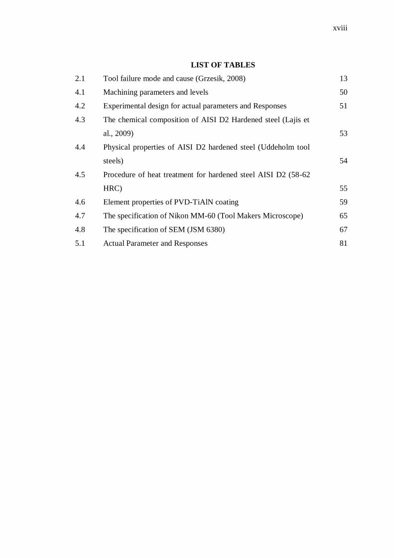
LIST OF TABLES
2.1 Tool failure mode and cause (Grzesik, 2008) 13
4.1 Machining parameters and levels 50
4.2 Experimental design for actual parameters and Responses 51
4.3 The chemical composition of AISI D2 Hardened steel (Lajis et
al., 2009) 53
4.4 Physical properties of AISI D2 hardened steel (Uddeholm tool
steels) 54
4.5 Procedure of heat treatment for hardened steel AISI D2 (58-62
HRC) 55
4.6 Element properties of PVD-TiAlN coating 59
4.7 The specification of Nikon MM-60 (Tool Makers Microscope) 65
4.8 The specification of SEM (JSM 6380) 67
5.1 Actual Parameter and Responses 81
xix
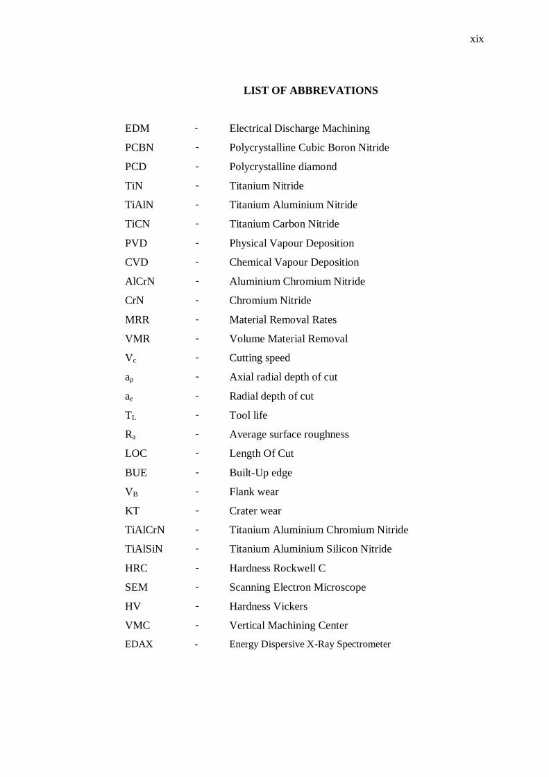
LIST OF ABBREVATIONS
EDM - Electrical Discharge Machining
PCBN - Polycrystalline Cubic Boron Nitride
PCD - Polycrystalline diamond
TiN - Titanium Nitride
TiAlN - Titanium Aluminium Nitride
TiCN - Titanium Carbon Nitride
PVD - Physical Vapour Deposition
CVD - Chemical Vapour Deposition
AlCrN - Aluminium Chromium Nitride
CrN - Chromium Nitride
MRR - Material Removal Rates
VMR - Volume Material Removal
Vc - Cutting speed
ap - Axial radial depth of cut
ae - Radial depth of cut
TL - Tool life
Ra - Average surface roughness
LOC - Length Of Cut
BUE - Built-Up edge
VB - Flank wear
KT - Crater wear
TiAlCrN - Titanium Aluminium Chromium Nitride
TiAlSiN - Titanium Aluminium Silicon Nitride
HRC - Hardness Rockwell C
SEM - Scanning Electron Microscope
HV - Hardness Vickers
VMC - Vertical Machining Center
EDAX - Energy Dispersive X-Ray Spectrometer
CHAPTER 1
1 INTRODUCTION
1.1 Recent trends in manufacturing by machining
The recent developments in science and technology highly emphasized in the field
manufacturing industries. The manufacturing industries are trying to decrease the
cutting costs, increase the quality of the machined parts and machine more difficult
materials. Machining efficiency is improved by reducing the machining time with
high cutting speed machining. However, when cutting hard material such as steels,
cast iron and super alloys, softening temperature and the chemical stability of the
tool material limits the cutting speed (Kishawy et al., 2000).Therefore, machining
hardened steel parts has become more pronounce in manufacturing process,
particularly in mould and die industries and subsequently mostly contributed in
making automotive and aerospace components. Due to the hardness of the material,
abrasive processes such as grinding and polishing have been typically required, but
advances in machine tool and cutting tool materials has allowed machining hardened
steels to become a realistic replacement for many grinding applications. Despite of
having outstanding machinery, no one could not expect the failure of tool life for
certain conditions in machining operation. Thus, it will become most apparent when
machining hard materials such as hardened steel (Lajis et al., 2008).
With the advent of several advanced diffcult-to-cut materials, and with the
availability of heat resistant has posed a great challenge in industries. Hardened steel
is one of these diffcult-to-cut materials(Chen et al., 2007). During the last few years,
2
numerous studies have been conducted to improve the machinability of this kind
materials and to explore and develop new techniques to minimize machining costs
maintaining the quality requirements of the machined direct manufacture of
components from hardened steel are expected to be substantial especially in the
context machining costs and leads times compared to traditional route of machining
in the annealed state followed by heat treatment, grinding or electrical discharge
machining (EDM), and manual finishing. However, there are several issues related to
this process that require further investigation, and the major issue among these is the
high temperatures at the tool-chip and tool-workpiece interfaces in conjuction with
the plastic deformation, both strongly affecting the surface integrity and the quality
of the machined product.
In today machining issues, the studies have been done to evaluate the
machinability of the AISI D2 hardened steel by using the cutting tool insert-coated
carbide. The reason is hardened steels AISI D tool group is extensively used in
making moulds and dies, but the machinability of this group is very poor. But despite
the extensive use and potential scope of AISI group D tool steel for cold forming
operations, most information about the machinability of AISI group D tool steel is
highly is needed (Koshy et al., 2002). Milling of hardened steel AISI D2 is usually a
finishing process, therefore a stable cutting process must be guaranteed first. A very
important indicator of the performance of metal cutting operation is the productivity
or volume material removed per unit time. The productivity enhancement of
manufacturing processes imposes the accelerations of the design and evolution of
improved cutting tools with respect to the achievement of a superior tribological
attainment and wear resistance. The trend to increase productivity has been the
instrumental in invention of newer and newer cutting tools with respect to material
and design (Fox-Rabinovich et al., 2005).
Other than cutting tool improvement and development, dry cutting is beneficial
because of the elimination of the cost the cutting fluid as well as the high cost of
fluid disposal. Hence, in dry cutting; the increasing need to boost productivity, to
machine more difficult materials and to improve quality in high volume has been the
driving force behind the development of cutting tool materials. For these reasons,
hard coating for cutting tools has been of the one important aspect of cutting tool
research development. These hard coatings are thin films that range from one layer to
hundreds of layers and have thickness that range from few nanometres to few
3
millimetres. These hard coatings have been proven to increase the tool life through
slowing down the wear phenomenon of the cutting tools. This increase in tool life
allows for less frequent tool changes, therefore can reduce the manufacturing cost,
but also reducing the setup time as well as the setup cost. In addition, to increasing
the tool life, hard coating deposited on cutting tools allows for improved and more
consistent surface roughness of the machined work piece. The surface roughness of
the machined work piece changes as the geometry of the cutting tool changes due to
wear, and slowing down the wear process means more consistency and better surface
finish (Derflinger et al., 1999; Chen et al., 2011).
Machining efficiency is improved by the reducing the machining time with high
cutting speed. When cutting the hard material such as steels, cast iron and super
alloys, softening temperature and the chemical stability of the material limits the
cutting speed. Therefore, it is necessary for tool materials to possess good high-
temperature and mechanical properties. While many ceramic materials such as TiC,
Al2O3 and TiN posses high temperature strength, they have lower fracture toughness
than that of conventional tool materials such as high-speed steels and cemented
tungsten carbides. The machining of hard and chemically reactive materials at higher
speeds is improved by deposited single and multi layer coatings on conventional tool
materials to combine the beneficial properties of ceramics and traditional tool
materials. The majority of cutting tools is use today employ in chemical vapour
deposition (CVD) or physical vapour deposition (PVD) hard coatings. The high
hardness, wear resistance and chemical stability of these coatings offer proven
benefits in terms of tool life and machining performance. Coated hard metals have
brought great influence in increasing productivity since their introduction. Since then
coatings have also been applied to high speed steel(HSS) especially in end millings.
Coatings acts as diffusion barrier; they prevent the interaction between chip formed
during the machining and the cutting material itself. The compounds which make up
the coatings used are extremely hard and so they are abrasion resistant (Kovalev et
al., 2009).
4
1.1.1 Machinability and surface integrity in machining
Numerous investigation have been carried out to improved the machinability (tool
life and tool wear performance) and surface integrity (surface roughness, surface
topography and surface metallurgy) of the hardened steels. In machining process, the
tool may experience repeated contact loads during interrupted cut, and the workpiece
may chemically interact with the tool material. The response of a tool material to the
above tribological condition dictates its performance. Moreover, the damages of a
cutting tool are influenced by the stress state and temperature at the tool surfaces,
the cutting conditions with the presence or not cutting fluid. In machining, the tool
damage mode and the rate of damage are very sensitive to changes in the cutting
operation and the cutting conditions. To minimize machining cost, it is not only to
find the most suitable tool and work combination for a given machining operation,
but also to reliably predict the tool life.
AISI D2 hardened steel have a poor machinability due to its low thermal
conductivity, which causes a high chemical reactivity caused by the elevation of the
temperature in the field cutting (Sun et al., 2009), indeed, the quality of machined
surface, is becoming more and more important to satisfy the increasing demands of
sophisticated component performance. However, surface integrity is one of the most
relevant parameters used for evaluating the quality of machined surface, indeed the
quality and performance of the product is directly related to the surface integrity
achieved by final machining. Surface integrity is influenced by a set of parameters.
Various researchers have analyzed the influence of cutting parameters on surface
state such as (Daymi et al., 2011; Kishawy et al., 2000; Umbrello et al., 2009 and
Amin et al., 2001). However, surface integrity including several criteria such as
roughness, microstructural changes, residual stress, microhardness and plastic
deformation at the surface. The microstructure at the surface layer can be changes as
a result of chemical changes caused by the tool, enlargement and elongations of the
grains are observed by Hughes et al.(2004).
Surface metallurgy includes the existence of microcracks, untempered, and
overtempered martensite imposed by the machining process, pull-out of carbides
from the grain boundary, intergranular attack, pits, tears, laps, protrusions, plastic
deformation and changes in the microhardness (Kishawy et al., 2000).These factors
5
determine the behaviour and service failures of the components produced. Otherwise,
the choice of manufacturing processes is based on cost, time and precision. Precision
of a surface is one of the topographical features which divided by two criteria:
dimensional accuracy and surface finish. However, another criterion has become
increasingly important: the performance of surface. The terms of performance has
different meanings depending on the contex, but is most likely linked to fatigue,
corrosion, wear and strength(Davim, 2010b). It is usually assumed that performance
is directly related surface integrity.
Therefore, the main interest in this study is to obtain longer tool life and high
productivity or high volume material removed in hard milling of AISI D2 using
coated carbide tool. With rapidly growing trends in developing advanced processing
technologies, manufactured components/products are expected to demonstrate
superior quality and enhanced functional performance. Material removal processes
continue to dominate among all manufacturing processes. The functional
performance of components from material removal processes is heavily influenced
by the quality and reliability of the surfaces produced both in terms of topography as
well as metallurgical and mechanical state of the subsurface layers (Jawahir et al.,
2011).
1.2 Problem Statement
Problems arise in machining hardened still is due to its high hardness and toughness
as well as its inhomogeous microstructure, which contributes to accelerated tool wear
and chipping. Besides that, increasing material removal rate (MRR) (i.e increasing
cutting speed,Vc and radial depth of cut,ae) leads to produce higher productivity,
however, it influences the tool wear deterioration rapidly, hence, reduces tool life due
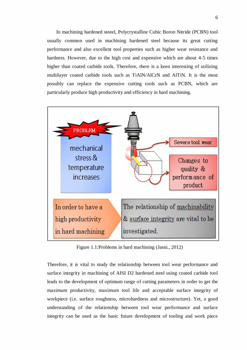
to mechanical stress and temperature increases. Figure 1.1shows problems in hard
machining. The progress of tool wear affects to the surface integrity on the
workpiece as well.
6
In machining hardened steeel, Polycrystalline Cubic Boron Nitride (PCBN) tool
usually common used in machining hardened steel because its great cutting
performance and also excellent tool properties such as higher wear resistance and
hardness. However, due to the high cost and expensive which are about 4-5 times
higher than coated carbide tools. Therefore, there is a keen interesting of utilizing
multilayer coated carbide tools such as TiAlN/AlCrN and AlTiN. It is the most
possibly can replace the expensive cutting tools such as PCBN, which are
particularly produce high productivity and efficiency in hard machining.
Figure 1.1:Problems in hard machining (Jasni., 2012)
Therefore, it is vital to study the relationship between tool wear performance and
surface integrity in machining of AISI D2 hardened steel using coated carbide tool
leads to the development of optimum range of cutting parameters in order to get the
maximum productivity, maximum tool life and acceptable surface integrity of
workpiece (i.e. surface roughness, microhardness and microstructure). Yet, a good
understanding of the relationship between tool wear performance and surface
integrity can be used as the basic future development of tooling and work piece
7
respectively. So, the potential cutting performances of coated carbide insert in
machining the AISI D2 hardened could be revealed. Coated carbide tools improve
wear resistance, increase tool life and enableto utilize higher cutting speeds used.
Therefore, there is a keen interest in the utilization of coated carbide tools that can
mostly replace expensive cutting tools (i.e. PCBN and ceramic) particularly in high
productivity of hard machining. Besides, from the investigation work of worn inserts
for the coated carbide tools revealed that the coatings were rapidly removed from the
substrate when high speed machining applied. As the coating was removed so
quickly, its effectiveness could be questioned.
1.3 Purpose of Study
This project is undertaking to relate the tool performance and surface integrity in
machining of AISI D2 hardened steels using advanced multilayer coated carbide tool
PVD-TiAlN. The objectives of this project are as below:
i. To investigate the effect of cutting variables (i.e cutting speed and radial
depth of cut) on tool wear performance and tool life of the cutting tools;
ii. To identify the effect of cutting variables (i.e cutting speed and radial
depth of cut) on surface integrity of the workpiece(i.e microstructure
analysis; microhardness; machined workpiece surface roughness);
iii. To explore the coating characteristics including the thickness of coating,
oxidation resistance and the microhardness of the coating.
8
1.4 Significances of Study
The study was conducted to evaluate the machining characteristics of AISI D2
hardened steel in a high speed CNC milling operation by using tungsten carbide
coated PVD-TiAlN. This research concentrates on the effect of cutting variables on
tool wear performance, tool life and machined workpiece surface
roughness.Machining database developed is likely to benefit the machining
practitioners and industries as it would help them in selecting optimum values of the
cutting parameters. An optimal selection of cutting parameters will satisfy the
economic objectives which are maximizing production rate and minimize the
production cost.Then, a good understanding of the relationship between tool wear
performance and surface integrity can be used as the basic of future development of
tooling and work piece respectively. So, the potential cutting performances of coated
carbide insert in machining the AISI D2 hardened could be revealed. The results can
be use to have a better understanding in today advanced machining technology.
1.5 Scopes of Study
The scope of this project is to perform machining operation for AISI D2 steel by
using PVD-TiAlN coated carbide cutting tool by using a high speed CNC Vertical
Milling (Mazak Tech). The parameters varying are cutting speed and radial depth of
cut while feed and depth of cut are kept constant.
This work was carried out with the aim to evaluate the performance of coated
carbide tools when end milling of AISI D2 hardened steels at various of cutting
speed and radial depth of cut. The effect of the varying cutting speed and radial depth
of cut on the tool wear, tool life and surface integrity machined work piece were
investigated.
In order to realize the objectives of the study to be successful and reasonably
implemented, the following significance study have been derived:
9
a) Cutting speed (>80 m/min), feed (0.05 mm/tooth), axial depth of cut (0.5mm)
and radial depth of cut (>5 mm).
b) Using a Vertical Milling CNC (Mazak Tech) machine to carry out the
machining experiments.
c) Coated carbide inserts with multilayer coating PVD-TiAlN (Sandvik
Coromant) was selected as the cutting tools for machining the work piece.
d) Conducting the machining operation on AISI D2 hardened steel (having a
typical hardness range of (58-62 HRC) as workpiece material.
e) The experiment was carried out under dry cutting condition.
f) Conducting experimental trials to investigate and evaluate the following
responses:
i. Tool life and tool wear using Tool Maker Microscope.
ii. Surface roughness measurement using Mitutoyo SJ-400.
iii. Microhardness measurement using Vickers Microhardness machine.
iv. Surface/sub-surface damage including white layer using Scanning
Electron Microscope (SEM)
v. Surface morphology of cutting tool wear and machined work piece
using Field Emission Scanning Electron Microscope (FE-SEM).
g) Analyzing data of gathered through experiments for both coated carbide
inserts (PVD-TiAlN) with;
a) Evaluation and comparison of the effect of cutting conditions on the
machinability of the work material.
b) Observation of machining characteristics of cutting tools due to the
cutting conditions.
10
1.6 Expected Study
Machining AISI D2 hardened steels at the higher cutting speed will cause rapid
chipping at the cutting edge which leads to catastrophic failure of the inserts. A
higher cutting speed also results in rapid cratering and/or plastic deformation of the
cutting edge. This is due to the heat generated which tends to be concentrated at the
cutting edge closer to the nose of the inserts. The heat affected zone is very small
when cutting AISI D2 hardened steel. The smaller heat affeced area produced is a
result of the shorter chip/tool contact length. It is mainly for this reason that the
cutting speeds are limited. The rapid tool failure and chipping at the cutting edge has
resulted in poor surface finish of the machined surface. It has caused not only higher
surface roughness values but also higher microhardness values and severe
microstructure alteration.
AISI D2 hardened steels are generally used in mould and die industries, which
are requires the great reliability, and therefore the tool life and surface integrity must
be maintained. According to the several researchers, when machining any component
it is essential to satisfy surface integrity requirements. However, during machining
and grinding operations, the surface of AISI D2 hardened steel is easily damaged
because of their poor machinability. In order to get better performance in machining
of AISI D2 hardened steel, continously increasing demand for higher metalworking
productivity is propelling the development of new manufacturing methods. Effective
implementation of these new techniques, such as dry machining and hard machining,
requires advanced carbide and cermet cutting tools. The performanace of the
advanced cutting tool materials can be enhanced by better and more resistant
coatings; development of these new cotings shows a clear trends towards complex
multicomponent and multilayer configurations.
CHAPTER 2
2 MACHINABILITY AND SURFACE INTEGRITY
This chapter explains briefly about the wear and surface integrity in the metal cutting
process. Special attention is directed toward the tool wear performance, coated
carbide tool and surface integrity such as surface topography and metallurgy. Thus,
the aim is to illustrated the fundamental concepts that would be used to explain the
results of this study.
2.1 Tool Wear
Tool wear leads to tool failure. According to several authors, the failure of cutting
tool occurs as premature tool failure (i.e tool breakage) and progressive tool wear.
Figure 2.1 shows some types of failures and wear on cutting tools.
Generally, wear of cutting tools depends on tool material and geometry,
workpiece materials, cutting parameters (i.e cutting speed, feed rate and depth of
cut), cutting fluids and machine-tool characteristics.
12
Figure 2.1: Types wear on cutting tools (Modern Metal Cutting, A practical
Handbook, Sandvik Coromant).
2.1.1 Tool Wear Types
Normally, wear is an undesirable and to be minimized. Tool wear occurs when the
machine surfaces rub together and a loss material from one or both surfaces results in
a change in the desired geometry of the system(Shaw, 2005). Tool wear adversely
affects tool life, the quality of the machined surface and its dimensional accuracy,
and consequently, the economics of cutting operation.
Wear is a gradual process, much like the wear of the tip of an ordinary pencil.
The rate of tool wear depends on tool and workpiece materials, tool geometry,
process parameters, cutting fluids, and the characteristics of the machine tool. Tool
wear and the changes in the tool geometry during cutting manifest themselves in
13
different ways, generally classified as flank wear, crater wear, nose wear, notching,
plastic deformation of the tool tip, chipping, and gross fracture.
There are lot types of tool wear such as crater wear, flank wear, crater wear,
notch wear, nose wear thermal cracks, chipping and plastic deformation. Table 2.1
illustrates some types of failures and wears on cutting tools.
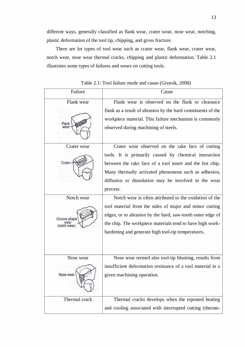
Table 2.1: Tool failure mode and cause (Grzesik, 2008)
Failure Cause
Flank wear
Flank wear is observed on the flank or clearance
flank as a result of abrasion by the hard constituents of the
workpiece material. This failure mechanism is commonly
observed during machining of steels.
Crater wear
Crater wear observed on the rake face of cutting
tools. It is primarily caused by chemical interaction
between the rake face of a tool insert and the hot chip.
Many thermally activated phenomena such as adhesion,
diffusion or dissolution may be involved in the wear
process.
Notch wear
Notch wear is often attributed to the oxidation of the
tool material from the sides of major and minor cutting
edges, or to abrasion by the hard, saw-tooth outer edge of
the chip. The workpiece materials tend to have high work-
hardening and generate high tool-tip temperatures.
Nose wear
Nose wear termed also tool-tip blunting, results from
insufficient deformation resistance of a tool material in a
given machining operation.
Thermal crack Thermal cracks develops when the repeated heating
and cooling associated with interrupted cutting (thermo-
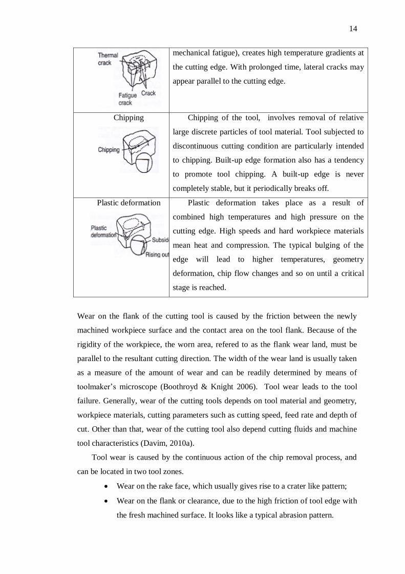
14
mechanical fatigue), creates high temperature gradients at
the cutting edge. With prolonged time, lateral cracks may
appear parallel to the cutting edge.
Chipping
Chipping of the tool, involves removal of relative
large discrete particles of tool material. Tool subjected to
discontinuous cutting condition are particularly intended
to chipping. Built-up edge formation also has a tendency
to promote tool chipping. A built-up edge is never
completely stable, but it periodically breaks off.
Plastic deformation
Plastic deformation takes place as a result of
combined high temperatures and high pressure on the
cutting edge. High speeds and hard workpiece materials
mean heat and compression. The typical bulging of the
edge will lead to higher temperatures, geometry
deformation, chip flow changes and so on until a critical
stage is reached.
Wear on the flank of the cutting tool is caused by the friction between the newly
machined workpiece surface and the contact area on the tool flank. Because of the
rigidity of the workpiece, the worn area, refered to as the flank wear land, must be
parallel to the resultant cutting direction. The width of the wear land is usually taken
as a measure of the amount of wear and can be readily determined by means of
toolmaker‘s microscope (Boothroyd & Knight 2006). Tool wear leads to the tool
failure. Generally, wear of the cutting tools depends on tool material and geometry,
workpiece materials, cutting parameters such as cutting speed, feed rate and depth of
cut. Other than that, wear of the cutting tool also depend cutting fluids and machine
tool characteristics (Davim, 2010a).
Tool wear is caused by the continuous action of the chip removal process, and
can be located in two tool zones.
Wear on the rake face, which usually gives rise to a crater like pattern;
Wear on the flank or clearance, due to the high friction of tool edge with
the fresh machined surface. It looks like a typical abrasion pattern.
15
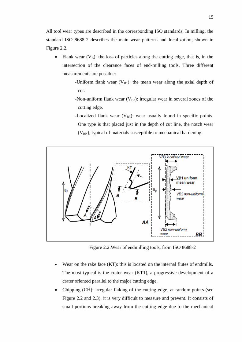
All tool wear types are described in the corresponding ISO standards. In milling, the
standard ISO 8688-2 describes the main wear patterns and localization, shown in
Figure 2.2.
Flank wear (VB): the loss of particles along the cutting edge, that is, in the
intersection of the clearance faces of end-milling tools. Three different
measurements are possible:
-Uniform flank wear (VB1): the mean wear along the axial depth of
cut.
-Non-uniform flank wear (VB2): irregular wear in several zones of the
cutting edge.
-Localized flank wear (VB3): wear usually found in specific points.
One type is that placed just in the depth of cut line, the notch wear
(VBN), typical of materials susceptible to mechanical hardening.
Figure 2.2:Wear of endmilling tools, from ISO 8688-2
Wear on the rake face (KT): this is located on the internal flutes of endmills.
The most typical is the crater wear (KT1), a progressive development of a
crater oriented parallel to the major cutting edge.
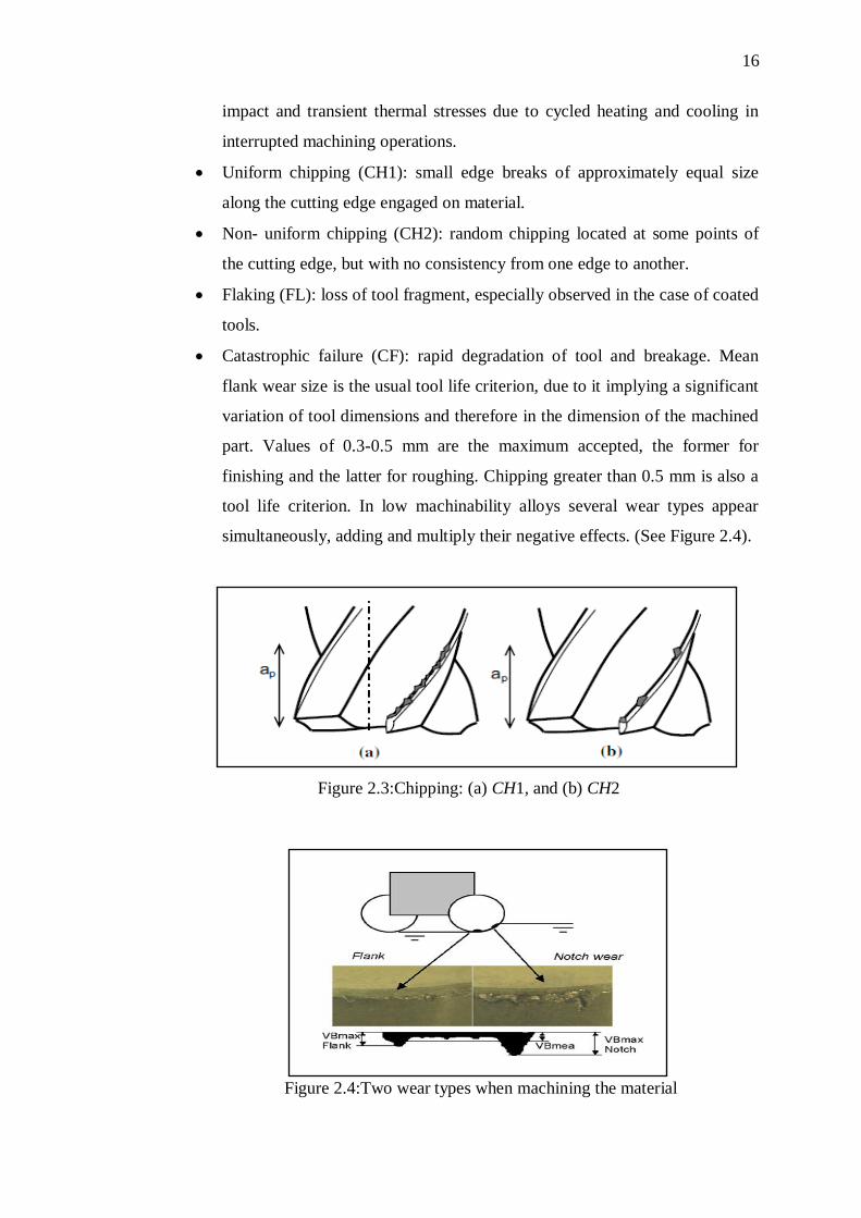
Chipping (CH): irregular flaking of the cutting edge, at random points (see
Figure 2.2 and 2.3). it is very difficult to measure and prevent. It consists of
small portions breaking away from the cutting edge due to the mechanical
16
impact and transient thermal stresses due to cycled heating and cooling in
interrupted machining operations.
Uniform chipping (CH1): small edge breaks of approximately equal size
along the cutting edge engaged on material.
Non- uniform chipping (CH2): random chipping located at some points of
the cutting edge, but with no consistency from one edge to another.
Flaking (FL): loss of tool fragment, especially observed in the case of coated
tools.
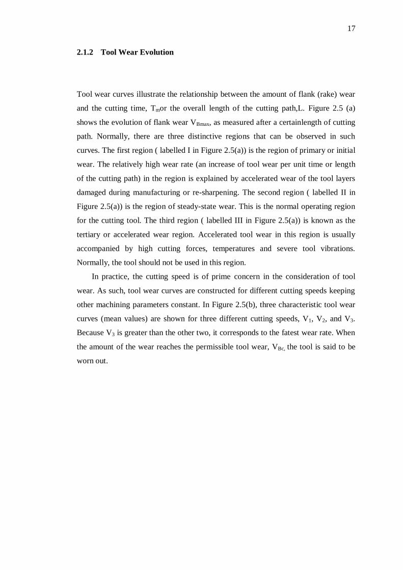
Catastrophic failure (CF): rapid degradation of tool and breakage. Mean
flank wear size is the usual tool life criterion, due to it implying a significant
variation of tool dimensions and therefore in the dimension of the machined
part. Values of 0.3-0.5 mm are the maximum accepted, the former for
finishing and the latter for roughing. Chipping greater than 0.5 mm is also a
tool life criterion. In low machinability alloys several wear types appear
simultaneously, adding and multiply their negative effects. (See Figure 2.4).
Figure 2.3:Chipping: (a) CH1, and (b) CH2
Figure 2.4:Two wear types when machining the material
17
2.1.2 Tool Wear Evolution
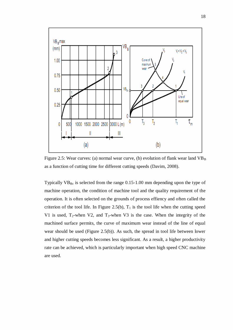
Tool wear curves illustrate the relationship between the amount of flank (rake) wear
and the cutting time, Tmor the overall length of the cutting path,L. Figure 2.5 (a)
shows the evolution of flank wear VBmax, as measured after a certainlength of cutting
path. Normally, there are three distinctive regions that can be observed in such
curves. The first region ( labelled I in Figure 2.5(a)) is the region of primary or initial
wear. The relatively high wear rate (an increase of tool wear per unit time or length
of the cutting path) in the region is explained by accelerated wear of the tool layers
damaged during manufacturing or re-sharpening. The second region ( labelled II in
Figure 2.5(a)) is the region of steady-state wear. This is the normal operating region
for the cutting tool. The third region ( labelled III in Figure 2.5(a)) is known as the
tertiary or accelerated wear region. Accelerated tool wear in this region is usually
accompanied by high cutting forces, temperatures and severe tool vibrations.
Normally, the tool should not be used in this region.
In practice, the cutting speed is of prime concern in the consideration of tool
wear. As such, tool wear curves are constructed for different cutting speeds keeping
other machining parameters constant. In Figure 2.5(b), three characteristic tool wear
curves (mean values) are shown for three different cutting speeds, V1, V2, and V3.
Because V3 is greater than the other two, it corresponds to the fatest wear rate. When
the amount of the wear reaches the permissible tool wear, VBc, the tool is said to be
worn out.
18
Figure 2.5: Wear curves: (a) normal wear curve, (b) evolution of flank wear land VBB
as a function of cutting time for different cutting speeds (Davim, 2008).
Typically VBBc is selected from the range 0.15-1.00 mm depending upon the type of
machine operation, the condition of machine tool and the quality requirement of the
operation. It is often selected on the grounds of process effiency and often called the
criterion of the tool life. In Figure 2.5(b), T1 is the tool life when the cutting speed
V1 is used, T2-when V2, and T3-when V3 is the case. When the integrity of the
machined surface permits, the curve of maximum wear instead of the line of equal
wear should be used (Figure 2.5(b)). As such, the spread in tool life between lower
and higher cutting speeds becomes less significant. As a result, a higher productivity
rate can be achieved, which is particularly important when high speed CNC machine
are used.
19
2.1.3 Mechanism of tool wear
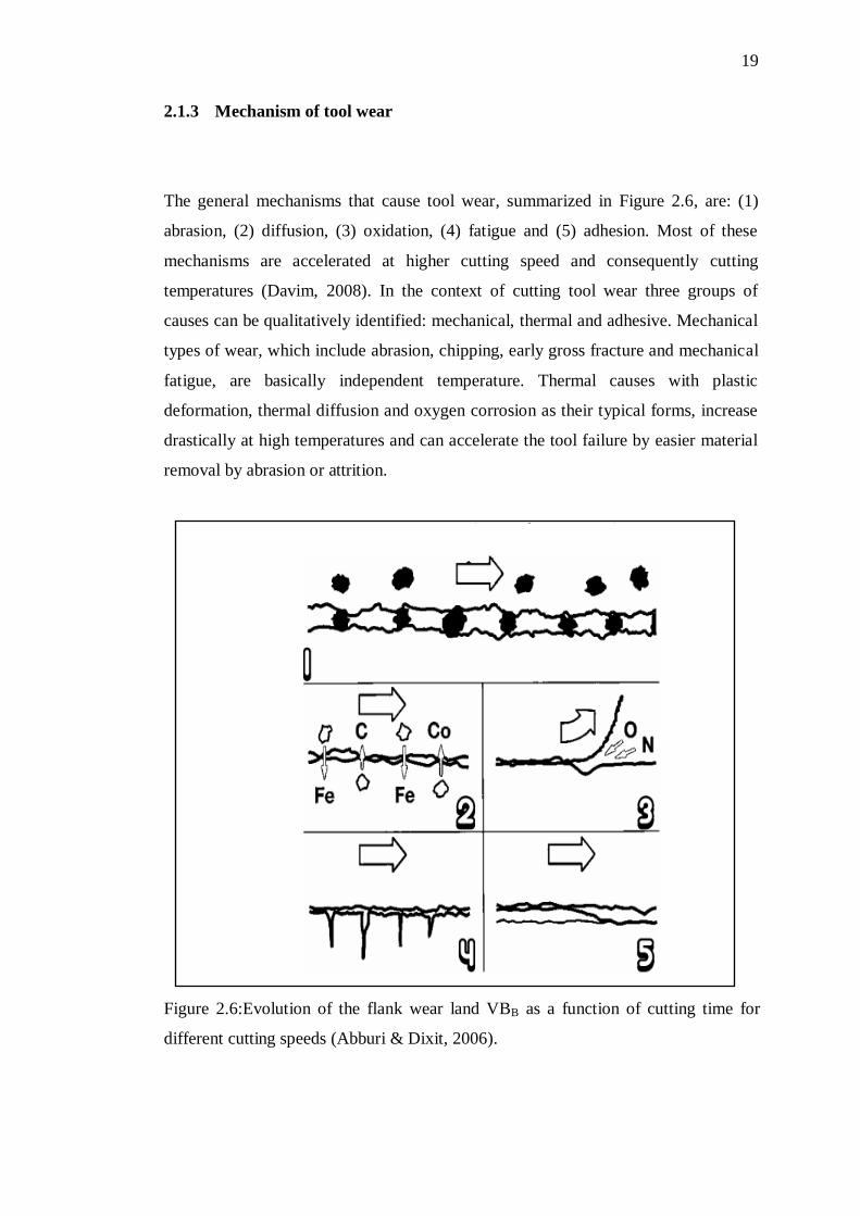
The general mechanisms that cause tool wear, summarized in Figure 2.6, are: (1)
abrasion, (2) diffusion, (3) oxidation, (4) fatigue and (5) adhesion. Most of these
mechanisms are accelerated at higher cutting speed and consequently cutting
temperatures (Davim, 2008). In the context of cutting tool wear three groups of
causes can be qualitatively identified: mechanical, thermal and adhesive. Mechanical
types of wear, which include abrasion, chipping, early gross fracture and mechanical
fatigue, are basically independent temperature. Thermal causes with plastic
deformation, thermal diffusion and oxygen corrosion as their typical forms, increase
drastically at high temperatures and can accelerate the tool failure by easier material
removal by abrasion or attrition.
Figure 2.6:Evolution of the flank wear land VBB as a function of cutting time for
different cutting speeds (Abburi & Dixit, 2006).
20
Abrasion wear occurs when hard particles slide against cutting tool, primarily on the
flank surface. The hard particles come from either work material‘s microstructure, or
are broken away from the cutting edge by brittle fracture. Moreover, they can also
result from a chemical reaction between the chips and cutting fluids when machining
steels or cast irons alloyed with chromium. Abrasive wear reduces the harder the tool
is relative to the particles in high temperatures, and generally depends on the
machining distance. Adhesive or attrition wear are the most significant types of wear
at lower cutting speeds. At high cutting speed, temperature-activated wear
mechanisms including diffusion (solution wear), chemical wear (oxidation and
corrosion wear), and thermal wear (superficial plastic deformation due to thermal
softening effect) occur (Gzersik, 2008).
2.1.4 Tool life
Tool life is important during machining since considerable time is lost whenever a
tool is replaced and reset. Tool life is the time a tool will cut satisfactorily and is
expressed as the minutes between changes of the cutting tool. The process of wear
and failures of cutting tools increases the surface roughness, and the accuracy of
workpieces deteriorates.
Tool life is the length of actual machining time beginning at the moment when a
tool is used and ending at the moment when the machining operation is stopped
because of the poor performance of tool. Different criteria can be used to judge the
moment at which the machining operation should be stopped. It is common consider
the tool life as over when the tool wear reaches certain stage. The tool life is affected
by several variables, the important ones being cutting speed, feed, coolant and radial
depth of cut used.
There are two inter-related causes for tool wear that affects life of tool:
mechanical abrasion and thermal erosion. Mechanical wear is dominant when low
cutting speeds are used or when the work piece possesses high machinability.
Thermal wear prevails when high cutting speeds are used with work piece having
low machinability. Thermal wear is due to diffusion, oxidation, and the fact that the
mechanical properties of the tool change as a result of the high temperature generated
21
during the cutting operation. In practical machining operations, the wear of the face
and flank of the cutting tool is not uniform along the active cutting edge; therefore it
is necessary to specify the locations and degree of the wear when deciding the
amount of wear allowable before regrinding the tool. When the work material and
tool shape are chosen for a particular machining operation, the most significant factor
affecting the tool life is the cutting speed (Boothroyd & Knight, 2006). Based on
Equation 2.1, tool life to be measured as the total length of cut, L (the tool failure
criteria is attained, VB= 0.3 mm) divided by feed rate, fr.
TL =LOC
fr (2.1)
Where:
TL = Tool life (min)
LOC = Length of cut of material removed (mm)
Fr = Feed rate (mm/min)
Increasing material removal rate (MRR) such as higher cutting speed, feed, depth of
cut and radial depth of cut to employ higher productivity. Equation 2.2 shows the
relation of volume material removal (VMR) to material removal rate (MRR) and tool
life (TL) (Arsecularatne et al., 2006). Furthermore, Equation 2.3 shows the derivation
of material removal rate (MRR).
VMR = MRR × TL (2.2)
Where:
VMR = Volume material removal (mm3)
MRR = Material removal rate (mm3/min)
TL = Tool life (min)
22
MRR = fr × ap × ae (2.3)
Where:
MRR = Material removal rate (mm3/min)
fr = feed rate (mm/min)
ap = depth of cut (mm)
ae = radial depth of cut (mm)
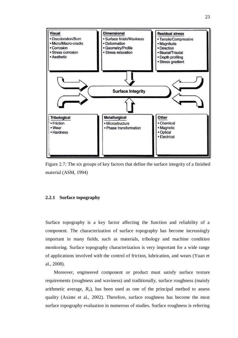
2.2 Surface integrity
Surface integrity can be simplistically divided into two parts: first, the external
aspects of topography, texture and surface finish and second the internal subsurface
aspects of metallurgy, hardness, white layer formation and so on. The concept of
surface integrity can be extended to any finishing operations to encompass six
different groups of key factors: visual, dimensional, residual stress, tribological,
metallurgical and other factors as illustrated in Figure 2.7. It should be noted that all
the parameters involved in the hard milling process have a direct influence on the
surface integrity of the part. On the other hand, the six groups of key factors
presented in the figure are not random, but are rather deterministic outcome of the
manufacturing process performed. In consequence, the determination of basic
relationships between mechanical, thermal and chemical aspects of a hard milling
process is crucial to successful improvement of a finishing process (Grzesik, 2008).
23
Figure 2.7: The six groups of key factors that define the surface integrity of a finished
material (ASM, 1994)
2.2.1 Surface topography
Surface topography is a key factor affecting the function and reliability of a
component. The characterization of surface topography has become increasingly
important in many fields, such as materials, tribology and machine condition
monitoring. Surface topography characterization is very important for a wide range
of applications involved with the control of friction, lubrication, and wears (Yuan et
al., 2008).
Moreover, engineered component or product must satisfy surface texture
requirements (roughness and waviness) and traditionally, surface roughness (mainly
arithmetic average, Ra), has been used as one of the principal method to assess
quality (Axinte et al., 2002). Therefore, surface roughness has become the most
surface topography evaluation in numerous of studies. Surface roughness is referring
24
to high frequency irregularities on the surface caused by the interaction of the
material microstructure and the cutting tool action. This relates directly to the
manufacturing unit event (the inherent generating mechanisms) and describes the
irregularities caused by each feed rate, abrasive grit, particle, or spark. In practice,
roughness is never separate with waviness and form, but only superimposed on top
of each other. So, these distinctions are therefore qualitative not quantitative.
However, roughness results from the manufacturing process rather than machine
tool, waviness is attributed to the individual machine and form errors are caused by
mutual effects such as insufficient fixturing of the part, straightness errors of the
guideways or thermal distortion of both the tool and the workpiece (Grzesik, 2008).
2.2.2 Surface metallurgy
During the machining operations, the workpiece material is exposed to thermal,
mechanical, and chemical energy that can lead to strain aging and recrystallization of
the material produce variety alterations of the subsurface layer illustrated
schematically in Figure 2.8. Due to the strain aging process, the material might
become harder but less ductile, and recrystallization might cause the material to
become less hard but more ductile. These thermal (high temperature and rapid
quenching) and mechanical (high stress and strain) effects are the main reasons for
the microstructural alterations in the material, as well as phase transformations and
plastic deformations (Yang et al., 1999). The primary important changes, strongly
influenced by machining operations and their parameters, are: microstructure and
hardness profile changes, as well as the introduced residual stresses. The principal
causes of surface alterations are as follows:
i. The high temperature or high temperature gradients developed during
the machining process.
ii. Plastic deformation and plastically deformed debris.
iii. Chemical reactions and subsequent absorption into the machined surface
(Gzesik, 2008)
156
REFERENCES
Abburi, N.R and Dixit, U.S.(2006). A knowlegde-based system for the prediction of
surface roughness in turning process. Robot Comput-Integr Manuf. 22:363-372.
Aihua, L., Deng, J., Haibing, C., Yangyang, C. and Jun, Z.(2012). Friction and wear
properties of TiN, TiAlN, AlTiN and CrAlN PVD nitride coatings.
International Journal of Refractory Metals and Hard Materials, 31, pp.82–88.
Alauddin, M., El Baradie, M.A. and Hashmi, M.S.J.(1995). Computer-aided analysis
of a surface-roughness model for end milling. Journal of Materials Processing
Technology 55(2): 123–127.
Altin, A., Nalbant, M. and Taskesen, A.(2007). The effects of cutting speed on tool
wear and tool life when machining Inconel 718 with ceramic tools. Materials &
Design 28(9): 2518–2522.
Amin, A.K.M.N, Rizal, M.A and Razman, M.(2001). Influence of chatter of VMC
arising during end milling operation and cutting conditions on quality of
machined surface. IIUM Engineering Journal.
Arsecularatne, J.A., Zhang, L.C., Montross, C. and Mathew, P.(2006). On machining
of hardened AISI D2 steel with PCBN tools. Journal of Materials Processing
Technology 171(2): 244–252.
Arunachalam, R.M., Mannan, M.A and Spowage, A.C.(2004). Surface integrity
when machining age hardened Inconel 718 with coated carbide cutting tools.
International Journal of Machine Tools and Manufacture 44(14): 1481–1491.
Aslan, E.(2005). Experimental investigation of cutting tool performance in high
speed cutting of hardened X210Cr12 cold work tool steel (62 HRC). Materials
& Design. 26: 21-27.
ASM Handbook. Surface Engineering Volume 5, Materials Park: ASM Int. 1994
Attanasio, A., Umbrello, D., Cappellini, C., Rotella, G. and M‘Saoubi, R.(2012).
Tool wear effects on white and dark layer formation in hard turning of AISI
52100 steel. Wear 286-287: 98–107.
Axinte, D.A, and Dewes, R.C.(2002). Surface integrity of hot work tool steel after
high speed milling-experimental data and empirical models. Journal of
Materials Processing Technology 127(3): 325–335 .
Baumann, G., Fecht, H.J. and Liebelt, S.(1996). Formation of white-etching layers
on rail treads. Wear. 191: 133–140.
157
Boothroyd, G. and Knight W.A.(2006). Fundamentals of Machining and Machine
Tools. Third Edition. Taylor & Francis.
Camuşcu, N. and Aslan, E.(2005). A comparative study on cutting tool performance
in end milling of AISI D3 tool steel. Journal of Materials Processing
Technology 170(1-2): 121–126.
Che-Haron, C.H., and Jawaid, A.(2005). The effect of machining on surface integrity
of titanium alloy Ti–6% Al–4% V. Journal of Materials Processing Technology
166(2): 188–192.
Chen, L., Yong, D., Xiang, X., Chang, K and Ming J.W.(2011). Int . Journal of
Refractory Metals and Hard Materials Improved properties of Ti-Al-N coating
by multilayer structure.RMHM 29(6): 681–685.
Chen, M., Jing, L. and Li, X.(2007). The Surface Integrity in Machining Hardened
Steel Skd11 for Die and Mold. Machining Science and Technology 11(1): 99–
116.
Davim, J.P.and Astakhov, V.P.Machining, London: Springer. 2008.
Davim, J.P. Machining of Hard Materials, London: Springer. 2010a.
Davim, J.P. Surface Integrity of Machining, London: Springer.2010b.
Daymi, A, Boujelbene, M.., Amara, B., Bayraktar,E. and Katundi, D.(2011). Surface
integrity in high speed end milling of titanium alloy Ti-6Al-4V. Materials
Science and Technology 27(1): 387–394.
Derflinger, V., Brändle,H. and Zimmermann,H.(1999). New hard/lubricant coating
for dry machining. Surface and Coatings Technology 113(3): 286–292.
El-Bestawi, M.A, El-Wardany, T.I , Yan, D and Tan, M.(1993). Performance of
Whisker-Reinforced Ceramic Tools in Milling Nickel-Based Superalloy. CIRP
Annals - Manufacturing Technology 42(1): 99–102.
El-Wardany, T.I., Kishawy, H.A. and Elbestawi, M.A.(2000). Surface Integrity of
Die Material in High Speed Hard Machining, Part 1: Micrographical Analysis.
Transactions of the ASME: 122.
Ezugwu, E.O, Bonney,J. and Yamane, Y.(2003). An overview of the machinability
of aeroengine alloys. Journal of Materials Processing Technology 134(2): 233–
253.
Ezugwu, E.O. and Tang, S.H. (1995). Surface abuse when machining cast iron (G-
17) and nickel-base superalloy (Inconel 718) with ceramic tools. Journal of
Materials Processing Technology. 55: 63–69.
158
Enzugwu, E.O., Wang, Z.M. & Okeke, C.I. (1999). Tool life and surface integrity
when machining Inconel 718 with PVD- and CVD-coated tools. Tribology
transactions. 42(2): 353-360
Fox-Rabinovich, G.S., Yamomoto,K., Veldhuis,S.C., Kovalev, A.I, and Dosbaeva,
G.K.(2005). Tribological adaptability of TiAlCrN PVD coatings under high
performance dry machining conditions. Surface and Coatings Technology
200(5-6): 1804–1813.
Ghani, J.A., Choudhury, I.A. and Masjuki, H.H.(2004). Wear mechanism of TiN
coated carbide and uncoated cermets tools at high cutting speed applications.
Journal of Materials Processing Technology 153-154: 1067–1073.
Ginting, A., and Nouari, M.(2009). Surface integrity of dry machined titanium
alloys. International Journal of Machine Tools and Manufacture 49(3-4): 325–
332.
Griffiths, B.(2001). Surface Integrity and Functional Performance. Manufacturing
Surface Technology. London: Penton Press.
Grzesik, W.(2008). Influence of tool wear on surface roughness in hard turning using
differently shaped ceramic tools. Wear 265(3-4): 327–335.
Grzesik,W.(2008). Advanced Machining Processes of Metallic Materials: Theory,
Modelling and Applications. First edition, Oxford, UK: Elsevier.
Gopalsamy, B.M., Mondal, B., Ghosh, S., Arntz, K. and Klocke, F.(2010).
Experimental investigation while hard machining of DIEVAR tool steel (50
HRC). Int J Adv Manuf Technol. 51(9-12): 853-869.
Gopalsamy, B.M., Mondal, B., Ghosh, S., Arntz, K. and Klocke, F.(2009).
Investigations on hard machining of Impax Hi Hard tool steel. Int J Material.
2:145-165.
Guo, Y.B. and Janowski, G.M.(2004). Microstructural characterization of white
layers formed during hard turning and grinding. Transactions of NAMRI/SME.
Vol 32.
Guerville, L. and Vigneau, J.(2004). Influence of machining conditions on residual
stresses, in: D. Dudzinski, A. Devillez, A. Moufki, D. Larrouquerre, V.
Zerrouki, J. Vigneau (Eds.). A review of developments towards dry and high
speed machining of Inconel 718 alloy. International Journal of Machine Tools
and Manufacture.44: 439–456.
Habeeb, H.H., Abou-El-Hossein, K.A, Mohammad, B. and Kadirgama, K.(2008).
Effect of tool holder geometry and cutting condition when milling nickel-based
alloy 242. Journal of Materials Processing Technology 201(1-3): 483–485.
159
Haron, C.H., Ginting, A. and Arshad, H.(2007). Performance of alloyed uncoated
and CVD-coated carbide tools in dry milling of titanium alloy Ti-6242S.
Journal of Materials Processing Technology, 185(1-3), pp.77–82.
Holmberg, K., Matthews, A. and Ronkainen, H.(1998). Coatings tribology—contact
mechanisms and surface design. Tribology International, 31(1-3), pp.107–120.
Huang, D.H., Hsun Hsu, C., Yen-Chun, L., Chi-Lung, C., Ko-Wei, W. and Wei-Yu
H.(2007). Thermal stability behaviors of Cr(N,O)/CrN double-layered coatings
by TGA/DTA analysis. Surface and Coatings Technology 201(15): 6681–6685.
Hughes, J.I., Sharman, A.R.C. and Ridgway, K.(2004). Workpiece surface integrity
and tool life issues when turning Inconel 718 nickel based superalloy.
Machining. Science Technology 8 (3)399-414.
Iqbal, A., Ning, H., Khan, I., Liang, L. and Dar, N.U.(2008). Modeling the effects of
cutting parameters in MQL-employed finish hard-milling process using D-
optimal method. Journal of Materials Processing Technology. 199: 379–390.
Jaharah, A.G, Choudhury, I.A, Masjuki, H.H and Che Hassan, C.H.(2009). Surface
Integrity of AISI H13 tool steel in end milling process. Journal of Mechanical
and Materials Engineering., 4(1), pp.88–92.
Jasni, N.A.H., Lajis, M.A. and Kamdani, K.(2012). Tool Wear Performance of
TiAlN/AlCrN Multilayer Coated Carbide Tool in Machining of AISI D2
Hardened Steel. Advanced Materials Research 488-489: 462–467.
Jawahir, I.S., Brinksmeier,E., M‘Saoubi, R., Aspinwall, D.K., Outeiro, J.C., Meyer,
D., Umbrello,D. and Jayal, A.D.(2011). Surface integrity in material removal
processes: Recent advances. CIRP Annals - Manufacturing Technology 60(2):
603–626.
Jawaid, A., Sharif, S. and Koksal, S.(2000). Evaluation of wear mechanisms of
coated carbide tools when face milling titanium alloy. Journal of Materials
Processing Technology 99(1-3): 266–274.
Jeong, Y.K., Kang, M.C., Kwon, S.H., Kim, K.H., Kim, H.G. and Kim, J.S.(2009).
Tool life of nanocomposite Ti–Al–Si–N coated end-mill by hybrid coating
system in high speed machining of hardened AISI D2 steel. Current Applied
Physics 9(1): S141–S144.
Kang, M.C., Kim, K.H., Shin, S.H, Jang, S.H., Park, J.H. and Kim, C.(2008). Effect
of the minimum quantity lubrication in high-speed end-milling of AISI D2 cold-
worked die steel (62 HRC) by coated carbide tools. Surface and Coatings
Technology 202(22-23): 5621–5624.
Kadirgama, K., Abou-El-Hossein, K.A., Noor, M.M., Sharma, K.V. and Mohammad,
B.(2011). Tool life and wear mechanism when machining Hastelloy C-22HS.
Wear. 270: 258-268.
160
Kim, S.W., Lee, D.W., Kang, M.C. and Kim, J.S.(2001). Evaluation of machinability
by cutting environments in high-speed milling of difficult-to-cut materials.
Journal of Materials Processing Technology. 111: 256-260.
Kishawy, H.A, and Elbestawi, M.A.(2000). Surface Integrity of Die Material in High
Speed Hard Machining , Part 1 : Micrographical Analysis.‖ 122(November): 2–
13.
Konig, W., Klinger, M., and Link, R. (1984). Machining Hard Materials with
Geometrically Defined Cutting Edges. Field of Applications and Limitations, ―
Annals of the CIRP, Vol.(39) pp.(61-64).
Koshy, P., Dewes,R.C. and Aspinwall, D.K.(2002). High speed end milling of
hardened AISI D2 tool steel (∼58 HRC). Journal of Materials Processing
Technology 127(2): 266–273.
Kovalev, A.I., Wainstein, D.L.,Rashkovskiy, A.Y, Fox-Rabinovich, G.S.,
Yamamoto, K., Veldhuis,S., Aguirre,M. and Beake, B.D.(2009). Impact of Al
and Cr alloying in TiN-based PVD coatings on cutting performance during
machining of hard to cut materials. Vacuum 84(1): 184–187.
Krain, H.R., Sharman, A.R.C and Ridgway, K.(2007). Optimisation of tool life and
productivity when end milling Inconel 718TM. Journal of Materials Processing
Technology 189(1-3): 153–161.
Lajis, M.A, Nurul Amin, A.K.M, Mustafizul Karim, A.N and Hafiz, A.M.K.(2009).
Preheating in End Milling of AISI D2 Hardened Steel with coated Carbide
Inserts. Journal of Advanced Material Research. 83-86: pp 56-66.
Lajis, M.A, and Turnad, L.G.(2008). Prediction of Tool Life in End Milling of
Hardened Steel AISI D2. Journal of Scientific Research.21(4): 592–602.
Lajis, M.A., Nurul Amin, A.K.M. and Mustafizul Karim, A.N.(2012). Surface
Integrity in Hot Machining of AISI D2 Hardened Steel. Advanced Materials
Research 500: 44–50.
Li, A., Jun, Z., Hanbing, L., Zhiqiang, P. and Zeming, W.(2011). Progressive tool
failure in high-speed dry milling of Ti-6Al-4V alloy with coated carbide tools.
International Journal of Advanced Manufacturing Technology 58(5-8): 465–
478.
Liu, Z.Q., Ai,X., Zhang, H., Wang, Z.T. and Wan, Y.(2002). Wear patterns and
mechanisms of cutting tools in high-speed face milling. Journal of Materials
Processing Technology 129(1-3): 222–226.
Liew, W.Y.H.(2010). Low-speed milling of stainless steel with TiAlN single-layer
and TiAlN/AlCrN nano-multilayer coated carbide tools under different
lubrication conditions. Wear 269(7-8): 617–631.
161
Mo, J.L. and Zhu, M.H.(2009). Tribological oxidation behaviour of PVD hard
coatings. Tribology International, 42(11-12), pp.1758–1764.
Modern Metal Cutting, A practical Handbook, Sandvik Coromant.
Okada, M., Akira, H., Ryutaro, T.and Takashi, U.(2011). Cutting performance of
PVD-coated carbide and CBN tools in hardmilling.‖ International Journal of
Machine Tools and Manufacture 51(2): 127–132.
Poomari, A. (2012). Study on Tool Life of Coated , Cryogenically Treated and
Coated and Plain Cermet Cutting Tools While Machining Steel. Journal of
Scientific Research. 85(3): 394–407.
Prengel, H.G., Jindal, P.C., Wendt, K.H., Santhanam, A.T and Hegde, P.L.(2001). A
new class of high performance PVD coatings for carbide cutting tools. Elsevier
Surface and Coatings Technology.
Pawade, R.S., S.Joshi, S., Brahmankar, P.K. and Rahman, M.(2007). An
investigation of cutting forces and surface damage in high-speed turning of
Inconel 718. 193: 139–146.
Prengel, H.G., Santhanamb, A.T, Penichb, R.M., Jindalb, P.C. and Wendt, K.H.
(1997). Advanced PVD-TiAlN coatings on carbide and cermet cutting tools.
Elsevier Surface and Coatings Technology.95: 597–602.
Prengel, H.G., Jindal, P.C., Wendt, K.H., Santhanam, A.T., Hegde, P.L. and Penich,
R.M.(2001). A new class of high performance PVD coatings for carbide cutting
tools. Elsevier Surface and Coatings Technology.139: 25–34.
Qin, F., Chou, Y.K., Nolen, D., Thompson, R.G.(2009). Coating thickness effects on
diamond coated cutting tools. Surface and Coatings Technology, 204(6-7),
pp.1056–1060.
Rababa, Khalid, S. and Ahmad, A.(2012). The Effect of Austenite Temperature on
the Microstructure , Mechanical Behavior , Hardness , and Impact Toughness of
AISI D2 Tool Steel. International Journal of Engineering Research and
Application.2(3): 2890–2896.
Rahim, E.A, and Sasahara, H. (2011). A study of the effect of palm oil as MQL
lubricant on high speed drilling of titanium alloys. Tribology International
44(3): 309–317.
Rigney, D.A. and Glaeser, W.A. (1978). The significance of near surface
microstructure in the wear process, Wear, 46: 241–250.
Sahin, Y. (2009). Comparison of tool life between ceramic and cubic boron nitride
(CBN) cutting tools when machining hardened steels. Journal of Materials
Processing Technology, 209(7), pp.3478–3489.
Sandvik Coromant CoroMill 390 catalogue at www.thomasskinner.com.
162
Sharif, S., and Rahim, E.A. (2007). Performance of coated- and uncoated-carbide
tools when drilling titanium alloy—Ti–6Al4V. Journal of Materials Processing
Technology 185(1-3): 72–76.
Shaw, M.C. Metal Cutting Principles. Clarendon Press,Oxford University
Press,1984,p.324.
Sun, J. and Guo, Y.B. (2009). A comprehensive experimental study on surface
integrity by end milling Ti–6Al–4V. Journal of Materials Processing
Technology 209(8): 4036–4042.
Siller, H.R., Vila, C., Rodríguez, C.A. and Abellán, J.B. (2009). Study of face
milling of hardened AISI D3 steel with a special design of carbide tools. Int J
Adv Manuf Technol. 40:12–25.
Soković, M., Kopač, J., Dobrzański, L.A and Adamiak, M.(2004). Wear of PVD-
coated solid carbide end mills in dry high-speed cutting. Journal of Materials
Processing Technology 157-158: 422–426.
Saedon, J.B., Soo, S.L., Aspinwall, D.K., Barnacle, A. and Saad, N.H. (2012).
Prediction and Optimization of Tool Life in Micromilling AISI D2 (∼62 HRC)
Hardened Steel. Procedia Engineering 41(Iris): 1674–1683.
Soković, M. (2007). Quality management in development of hard coatings on cutting
tools. Journal of Achievements in Materials and Manufacturing Engineering.
24(1): 421–429.
Tonshoff, K., Karpuschewski, B., Mohlfeld, A., Leyendecker, T., Erkens, G. and
Wenke, R. (1998). Performance of oxygen-rich TiALON coatings in dry cutting
applications. Elsevier Surface and Coatings Technology. 109: 535–542.
Trent, E.M. and Wright, P.K. (2000). Metal Cutting. Fourth Edition. Newton:
Butterworth-Heinemann.
Tuffy, K., Byrne, G. and Dowling, D .(2000). Determination of the optimum TiN
coating thickness on WC inserts for machining carbon steels. Journal of
Materials Processing Technology. 156: 1861–1866.
Torrance, A.A. and Cameron, A. (1974). Surface transformations in scraffing. Wear.
28: 299–311.
Uddeholm tool steels, publications ―Steels for Cold Work Tooling‖.
Ulutan, Durul, and Tugrul Ozel. (2011). Machining induced surface integrity in
titanium and nickel alloys: A review. International Journal of Machine Tools
and Manufacture 51(3): 250–280.
Umbrello, D., and Filice, L. (2009). Improving surface integrity in orthogonal
machining of hardened AISI 52100 steel by modeling white and dark layers
formation. CIRP Annals - Manufacturing Technology 58(1): 73–76.
163
Veprek, S. and Veprek-heijman, M.J.G.(2008). Industrial applications of superhard
nanocomposite coatings. Surface & Coatings Technology , 202, pp.5063–5073
Vivancos, J., Luis, C.J., Costa, L. and Ortı́z, J.A.(2004). Optimal machining
parameters selection in high speed milling of hardened steels for injection
moulds. Journal of Materials Processing Technology 155-156: 1505–1512.
Warren, A.W. and Guo Y.B.(2006). On the clarification of surface hardening by hard
turning and grinding. Trans.NAMRI/Sme 34,309-316.
Yahya, Z. (2005). High-speed end-milling of AISI 304 stainless steels using new
geometrically developed carbide inserts. Journal of Materials Processing
Technology 163: 596–602.
Yang, X. and Liu, C.R. (1999). Machining titanium and its alloys. Machining
Science and Technology. 3(1): 107–139.
Yuan, C.Q., Peng, Z., Yan, X.P. and Zhou, X.C. (2008).Surface roughness evolutions
in sliding wear process. Wear.265: 341–348.
Zhang, B., Shen, W., Liu, Y., Tang, X. and Wang, Y. (1997). Microstructures of
surface white layer and internal white adiabatic shear band. Wear. 211: 164–
168.