wheel press gage - wheel shop automation user guide.pdf · the wheel press gage is used to record...
TRANSCRIPT

Revised 2014‐01‐09
WheelPressGageA component of the Wheel Shop Management Suite (WSMS)
User Guide

©2013 Arkansas Industrial Computing ii
ContentsIntroduction .................................................................................................................................................. 1
System Requirements ................................................................................................................................... 2
Installing Wheel Press Recorder .................................................................................................................. 3
Setup ............................................................................................................................................................. 7
Initial Setup ............................................................................................................................................... 7
General ...................................................................................................................................................... 8
Chart .......................................................................................................................................................... 9
Press ........................................................................................................................................................ 10
Calibration ............................................................................................................................................... 12
Distance............................................................................................................................................... 13
Force ................................................................................................................................................... 15
Installation .................................................................................................................................................. 16
Distance Transducer ............................................................................................................................... 17
Pressure Transduce ................................................................................................................................. 19
Power Requirements .............................................................................................................................. 21
Appendix A: Frequently Asked Questions (FAQ) ........................................................................................ 22
Appendix B: License .................................................................................................................................... 23
Appendix C: Press Settings ......................................................................................................................... 26
Appendix D: Contact Information ............................................................................................................... 27

©2013 Arkansas Industrial Computing 1
Introduction
Wheel Press Gage The Wheel Press Gage is used to record force/distance graphs on a wheel mounting press. Additional data may be entered, such as operator name, serial number, wheel type, and wheel diameter. The operator sets the values for minimum and maximum force limits. The program will automatically recognize a misfit caused by not reaching the minimum force or exceeding the maximum force and mark the graph as a misfit; however, wheel shop personnel must review each chart for correctness per Association of American Railroad (AAR) requirements. By installing and/or using the Wheel Press Gage, you indicate that you have read, understand, and accept the Software License Agreement found in Appendix B.

©2013 Arkansas Industrial Computing 2
SystemRequirements
This application has minimum system requirements as described below. These requirements must be
met in order for the application to operate as designed.
This application supports the following Microsoft Windows operating systems.
Windows 7 1
Windows Server 2008/2008 R2 1
Windows Vista Business/Ultimate 1
Windows Server 2003 SP2 1
Windows XP SP3 1
The application requires the Microsoft .Net Framework 3.5 Full which can be obtained from Microsoft at http://www.microsoft.com/en‐us/download/details.aspx?id=17718
The application requires the following hardware at a minimum.
2.0 GHz Processor
1 GB installed RAM
100 MB available disk space
Ethernet Card
1 When installed on a 64 bit operating system, the application will run in a subsystem of Windows called WOW64 (Windows‐on‐Windows 64 bit). WOW64 is included on all 64 bit versions of Windows and is designed to make differences between the operating systems transparent to the user.
©2013 Arkansas Industrial Computing 3
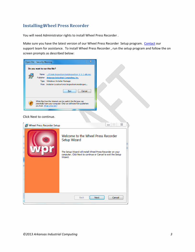
Installing�WheelPressRecorder You will need Administrator rights to install Wheel Press Recorder .
Make sure you have the latest version of our Wheel Press Recorder Setup program. Contact our
support team for assistance. To install Wheel Press Recorder , run the setup program and follow the on
screen prompts as described below:
Click Next to continue.

©2013 Arkansas Industrial Computing 4
Accept the license agreement and click Next.
Select the location where you would like to install Wheel Press Recorder to and click Next.

©2013 Arkansas Industrial Computing 5
Click Install to being the installation.
You may be asked to allow the setup program to install Wheel Press Recorder on your computer. Select
Yes.

©2013 Arkansas Industrial Computing 6
When the installation has completed, click Finish to close the setup application.

©2013 Arkansas Industrial Computing 7
Setup To enter the setup mode of the WPG, a numeric password must be supplied. Enter the numbers on the touchpad and press the Enter key. The default password is 9540. The password may be changed by editing the Password parameter in the C:\WPG\wpg.ini configuration file.
InitialSetup
The initial setup mode is normally used to provide a rough calibration if the press dimensions are known
prior to shipment. If the parameter InitialSetupComplete is set to false in the C:\WPG\wpg.ini
configuration file and the WPG program is restarted, then the following screen will appear. Fill in values
for the prompts to set some default calibration values. Pressure transducer max range will normally be
3000 psi. Press bore diameter depends on the press. Distance transducer max stroke is normally 60
inches.

©2013 Arkansas Industrial Computing 8
General The current version number and date of the WPG is displayed along with the previous version (if any) of the program. If a previous version exists there will be a button allowing the user to revert to the previous program version. See THESECTIONBELOW for details on how to update the program.

©2013 Arkansas Industrial Computing 9
Chart This setup page is used to configure the displayed and printed charts. See below for a description of each setting:
Distance Axis Scale – Maximum scale value for Distance Axis on displayed and printed charts. Minimum scale value is 0.
Force Axis Scale – Maximum scale value for Force Axis on displayed and printed charts. Minimum scale value is 0.
Chart Reset Time – Time in seconds after a mount that the chart will be displayed. Set from 0 to 90 seconds.
Distance Axis Label – Distance axis label on displayed and printed charts
Force Axis Label – Force axis label on displayed and printed charts
Wheel String Label – Description for string value that operator enters for each wheel (normally should be Wheel Type)
Wheel Number Label – Description for number value that operator enters for each wheel (Wheel Diameter or Tape Size)

©2013 Arkansas Industrial Computing 10
Press This setup page is used to configure how the recorder reacts while mounting a wheel.
‐ Start Distance o The distance reading before recording mode starts must be greater than this value to
trigger chart recording mode. This value is also set during Distance Calibration. Once the recording mode is triggered, the displayed distance value will be relative to the point at which the recording started. Thus, the chart will display only the distance moved during the mount.
‐ Start Pressure o This is the other trigger to start recording. The force must be greater than this value at
the same time that the distance reading is greater than Start Distance. ‐ Reset Pressure
o If the distance reading is less than Start Distance and the force reading is less than this value, then the recording chart will be reset and cleared. This allows “bumping” of the wheel prior to the mount.

©2013 Arkansas Industrial Computing 11
‐ Sensitivity o This value will alter the sensitivity of the force and distance readings. A higher value will
be more sensitive to fast changes in force or distance. The value ranges from 0 to 99. ‐ Force Drop Percent
o During the mount recording, the force peak is constantly evaluated. When the force decreases by this percentage from the peak, then the recording is finished. Force MUST drop by this amount to finish the recording. Also, this value may have to be increased if any force dips during the mount cause a premature ending of recording. Set the value from 5% to 90%.
©2013 Arkansas Industrial Computing 12
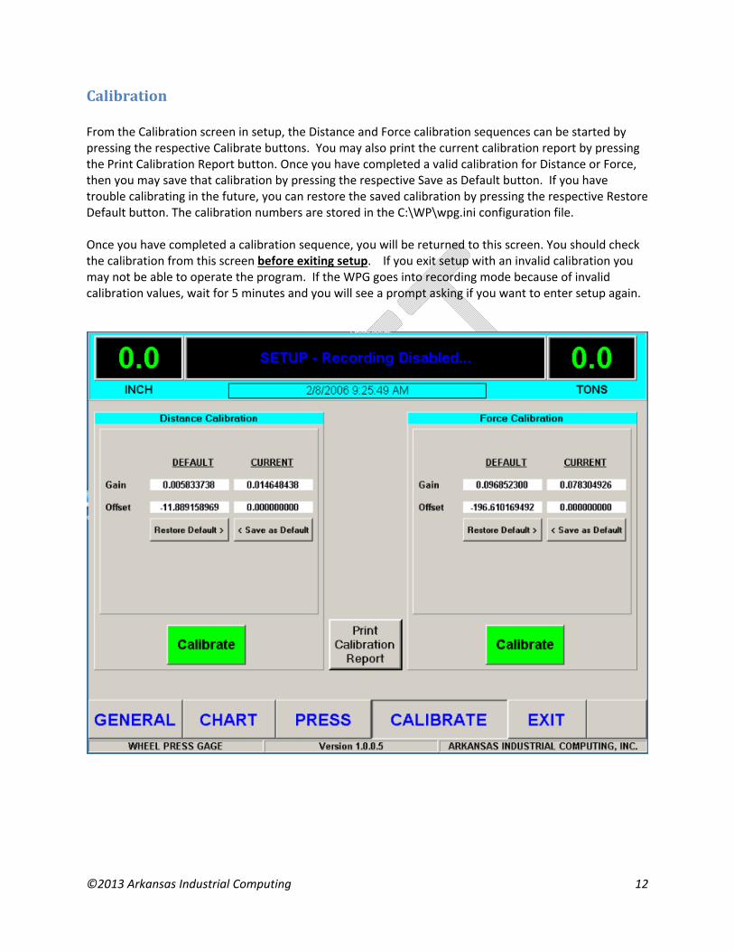
Calibration From the Calibration screen in setup, the Distance and Force calibration sequences can be started by pressing the respective Calibrate buttons. You may also print the current calibration report by pressing the Print Calibration Report button. Once you have completed a valid calibration for Distance or Force, then you may save that calibration by pressing the respective Save as Default button. If you have trouble calibrating in the future, you can restore the saved calibration by pressing the respective Restore Default button. The calibration numbers are stored in the C:\WP\wpg.ini configuration file. Once you have completed a calibration sequence, you will be returned to this screen. You should check the calibration from this screen before exiting setup. If you exit setup with an invalid calibration you may not be able to operate the program. If the WPG goes into recording mode because of invalid calibration values, wait for 5 minutes and you will see a prompt asking if you want to enter setup again.

©2013 Arkansas Industrial Computing 13
Distance The calibration of the distance transducer is based on recording the values of 2 positions of travel: one low and one high. Low Point Position the ram so that it is fully retracted. Enter the Low Calibration Point value (normally 0) and press the Next button at the bottom right of the screen. High Point Now move the ram to the fully extended position and measure how far it has moved. Enter the measured value as the High Calibration Point below. Press the Next button while the ram is still in the extended position. Accept Calibration The Counts value for the Low Calibration Point and High Calibration Point should differ by at least 1000 (assuming the maximum ram stroke is greater than 14 inches). Press the Accept button to save the calibration values.

©2013 Arkansas Industrial Computing 14
Start Distance To finalize the distance calibration, move the press ram to the minimum distance for contacting the axle or wheel and retract another 2 inches. Press the Finish button. This will be the Start Distance point for graphing purposes. The distances must be greater than this value for the Wheel Press Gage to start recording a mounting graph.

©2013 Arkansas Industrial Computing 15
Force The Force calibration is accomplished by recording the signal from the pressure transducer and matching those values to the press Master Gage (dial gauge) in units of force (normally Tons). Two values of the pressure transducer are recorded, one on the low end and one of the high end of the range used during the press. First, attach a pressure hand pump to the quick‐connect valve located next to the pressure transducer. Close the hand valve to isolate the pressure transducer and Master Gage from the press hydraulic system. Low Point Enter a value in Force units (normally Tons) for the Force Low Calibration Point. Now pump the hand pump to produce that exact number for Force units on the Master Gage. Once the Master Gage reading matches the entered Force Low Calibration Point value exactly, press the next button. High Point Enter a value in Force units (normally Tons) for the Force High Calibration Point. Now pump the hand pump to produce that exact number of Force units on the Master Gage. Once the Master Gage reading exactly matches the entered Force High Calibration Point value, press the Next button. Accept Calibration The Counts value for the Low Calibration Point and High Calibration Point should differ by at least 1000 (assuming a properly sized press ram). Press the Accept button to save the calibration values.

©2013 Arkansas Industrial Computing 16
Installation There are three main components of the system to be installed. WPG Enclosure – The WPG enclosure should be mounted as close to the press as possible so that the operator can easily view the chart while operating the press. The box should be protected from any excessive vibration or shock caused by press operation. Distance Transducer – The distance transducer is used to record the linear position of the press ram. It uses a stainless steel cable that must be attached to the ram. The transducer itself must be mounted to the press. Pressure Transducer – The pressure transducer must be installed into the hydraulic system lines as closely as possible to the press Master Gage (dial gauge).

©2013 Arkansas Industrial Computing 17
DistanceTransducer The Distance Transducer cable must be attached to the end of the press ram cylinder so that the cable extends in parallel with the ram. The Distance Transducer body should be mounted to the press. The cable should be a straight as possible (both horizontally and vertically) to prevent cable guide wear and must be free from obstructions for the full length of the ram stroke.

©2013 Arkansas Industrial Computing 18

©2013 Arkansas Industrial Computing 19
PressureTransduce The pressure transducer and associated components must be installed so that it can be isolated with the master gage (dial pressure gauge) to allow for calibration. In the following picture, the fittings supplied should be inserted into the hydraulic line as closely to the master gage as possible. The Shut‐Off valve should be closed only during calibration to isolate the Hand Pump connection, pressure transducer, and master gage from the rest of the hydraulic system.
Once the Pressure Transducer is installed into the hydraulic line, the cable must be run to the recorder. 24V DC loop power is supplied to the recorder on pin 1. The 4‐20ma measurement signal is output to the recorder on pin 2.

©2013 Arkansas Industrial Computing 20

©2013 Arkansas Industrial Computing 21
PowerRequirements The Wheel Press Gage requires computer grade 120V AC power. Computer grade poser is defined as electricity meeting the Institute of Electrical and Electronic Engineers Standard 446‐1987. This standard sets time and voltage intervals which electronic equipment must tolerate without malfunction. A good quality Uninterruptible Power Supply is highly recommended if shop power is subject to frequent surges or sags (such as may happen when other nearby equipment starts or stops).

©2013 Arkansas Industrial Computing 22
AppendixA:FrequentlyAskedQuestions(FAQ)
<Insert a list of the most common problems/questions along with their solutions. >
<Example>
Q. How do I …?
A. Verify … If that doesn’t solve your problem you can also try…
Q. When I do XYZ I get results PDQ. What could be wrong?
A. You should be performing steps ABC. Try the following…
</Example>

©2013 Arkansas Industrial Computing 23
AppendixB:License
WHEEL SHOP MANGEMENT SUITE END USER LICENCSE AGREEMENT
IMPORTANT NOTICE: Read Before Installing or Using Software
The following software products offered to you directly by Arkansas Industrial Computing (“AIC”) of 6100 Getty Drive, Suite N, North Little Rock, AR 72117 (voice 501-834-9540) is offered only for use in accordance with the terms and conditions of the WSMS End User License Agreement below.
BY INSTALLING OR USING ANY LICENSED SOFTWARE YOU WILL INDICATE THAT YOU HAVE READ, UNDERSTOOD, AND ACCEPT THESE TERMS AND CONDITIONS AND BECOME A PARTY TO THIS AGREEMENT. IF YOU ARE UNABLE OR UNWILLING TO ENTER AND COMPLY WITH THIS AGREEMENT, DO NOT ATTEMPT TO INSTALL OR USE ANY LICENSED SOFTWARE. INSTEAD, PROMPTLY RETURN ANY MATERIALS THAT WERE PROVIDED TO YOU. CONTACT AIC IF YOU WISH TO DISCUSS THE AGREEMENT BELOW, BEFORE YOU ATTEMPT TO INSTALL OR USE ANY PRODUCT.
WSMS END USER LICENSE AGREEMENT
LICENSE: Subject to the terms and conditions of this Agreement, AIC hereby grants to you a non-exclusive, non-transferable license to use the Licensed Software on one computer. This includes reproducing the Licensed Software, but only as reasonably required to ensure appropriate back-up practices are followed. All copies must bear all copyright and other proprietary rights notices which appear on the Licensed Software as originally provided by AIC. Subject to the license expressly granted above, you obtain no right, title, interest or other license in or to any Product, including but not limited to any copyright, patent, trade secret, trademark, or other proprietary rights therein. All whole and partial copies of the Licensed Software remain the property of AIC and will be considered part of the Licensed Software for the purpose of this Agreement.
Unless expressly permitted by this Agreement, or otherwise by applicable law or by AIC in writing, you shall not: (i) use, reproduce, modify, adapt, translate, update or transmit any Licensed Software, in whole or in part; (ii) rent, lease, license, transfer, or otherwise provide access to any Licensed Software; (iii) alter, remove, or cover trademarks or proprietary notices in or on any Licensed Software; (iv) export any Licensed Software from the country in which it was provided to you by AIC; (v) decompile, disassemble, decrypt, extract or otherwise attempt or assist others to reverse engineer any Licensed Software, except as necessary, when permitted by an applicable law, to correct defects or achieve interoperability with complimentary programs, for your purposes only, but only if AIC has refused to provide the necessary

©2013 Arkansas Industrial Computing 24
information or assistance. Unless AIC has provided you with express written consent, the Licensed Software may not be used in any application in which the failure of the Licensed Software could lead directly to death, personal injury, or severe physical or property damage (collectively, “High-Risk Activities”). AIC EXPRESSLY DISCLAIMS ANY EXPRESS OR IMPLIED WARRANTY OR CONDITION OF FITNESS FOR HIGH-RISK ACTIVITIES.
WARRANTY: AIC cannot warrant that any Licensed Software will function in accordance with related documentation in every combination of hardware platform, software environment, and Licensed Software configuration.
LIMITATIONS: EXCEPT AS EXPRESSLY WARRANTED ABOVE, THE LICENSED SOFTWARE AND ANY ASSOCIATED AIC MEDIA ARE PROVIDED “AS IS” WITHOUT OTHER WARRANTIES OR CONDITIONS OF ANY KIND, INCLUDING BUT NOT LIMITED TO IMPLIED WARRANTIES AND CONDITIONS OF MERCHANTABILITY, FITNESS FOR A PARTICULAR PURPOSE AND NON-INFRINGEMENT. YOU ASSUME THE ENTIRE RISK AS TO THE RESULTS AND PERFORMANCE OF THE LICENSED SOFTWARE. NOTHING STATED IN THIS AGREEMENT WILL IMPLY THAT THE OPERATION OF ANY LICENSED SOFTWARE WILL BE UNINTERRUPTED OR ERROR FREE OR THAT ERRORS WILL BE CORRECTED. OTHER WRITTEN OR ORAL STATEMENTS BY AIC, ITS REPRESENTATIVES OR OTHERS DO NOT CONSTITUTE WARRANTIES OF AIC.
IN NO EVENT WILL AIC (OR IT’S OFFICERS, EMPLOYEES, AGENTS, SUPPLIERS, DISTRIBUTORS, OR LICENSORS - COLLECTIVELY “ITS REPRESENTATIVES”) BE LIABLE TO YOU FOR ANY INDIRECT, INCIDENTAL, SPECIAL, OR CONSEQUENTIAL DAMAGES WHATSOEVER, INCLUDING BUT NOT LIMITED TO LOST REVENUE, LOST OR DAMAGED DATA OR OTHER COMMERCIAL OR ECONOMIC LOSS, ARISING OUT OF OR RELATING TO ANY BREACH OF THIS AGREEMENT, ANY USE OR INABILITY TO USE THE LICENSED SOFTWARE, OR ANY CLAIM MADE BY A THIRD PARTY, EVEN IF AIC OR IT’S REPRESENTATIVES HAVE BEEN ADVISED OF THE POSSIBILITY OF SUCH DAMAGE OR CLAIM.
IN NO EVENT WILL THE AGGREGATE LIABILITY OF AIC AND IT’S REPRESENTATIVES FOR ANY DAMAGES OR CLAIMS ARISING OUT OF OR RELATING TO THIS AGREEMENT OR ANY LICENSED SOFTWARE, WHETHER IN CONTRACT, TORT, OR OTHERWISE, EXCEED THE LICENSE FEES YOU PAID FOR THE USE OF THE LICENSED SOFTWARE UNDER THIS AGREEMENT. AIC’S AND IT’S REPRESENTATIVE’S LIMITATION OF LIABILITY IS CUMULATIVE WITH ALL OF AIC’S AND IT’S REPRESENTATIVE’S PAYMENTS IN SATISFACTION OF THEIR LIABILITIES BEING AGGREGATED TO DETERMINE SATISFACTION OF THE LIMIT.
These limitations shall apply whether or not the alleged breach is a fundamental breach of contract. Some jurisdictions curtail limitations of liability for incidental or consequential damages, and/or limitations of implied warranties. Therefore, to the extent prohibited by applicable law, the above limitations may not apply to you.

©2013 Arkansas Industrial Computing 25
TERM: This Agreement commences upon your acceptance (as described above) and will end when terminated. You may terminate this Agreement at any time. It will be deemed to terminate immediately if you fail to comply with any material term herein. Upon termination, your license rights end and you shall immediately destroy all whole or partial copies of all Licensed Software in your possession or control.
GENERAL: This Agreement is governed by and will be construed in accordance with the laws in force in the State of Arkansas, United States of America without regard to the conflict of laws provisions therein. The parties expressly disclaim the provisions of the United Nations Convention on Contracts for the International Sale of Goods. This Agreement constitutes the entire agreement between you and AIC pertaining to the Licensed Software and any associated AIC media, and supersedes all prior or contemporaneous agreements, understandings, negotiations, and discussions, whether oral or written. No amendment or waiver of any term of this Agreement will be binding unless executed in writing by the parties. Subject to the export restrictions provided above, you are entitled to assign this Agreement to a third party who has provided AIC with prior written acknowledgement of their acceptance of the terms and conditions herein. In such a case you will transfer all copies of the Licensed Software and any associated media to the assignee. The provisions of this Agreement will ensure to the benefit of and will be binding upon the parties and their respective successors and permitted assigns. If any provision of this Agreement is held by a court of competent jurisdiction to be illegal, invalid, or unenforceable, the remaining provisions shall remain in full force and effect.

©2013 Arkansas Industrial Computing 26
AppendixC:PressSettings

©2013 Arkansas Industrial Computing 27
AppendixD:ContactInformation Wheel Shop Automation 6100 Getty Drive Suite N Sherwood, AR 72117 Online Support Visit our website at www.wheelshopautomation.com for 24/7 technical information and available downloads Email us at [email protected] Phone Support (Existing support contract or credit card required) Call 1‐501‐834‐9540 or 1‐877‐834‐9540 (toll free)