wifibot 6wd english guide - freerbouraoui.free.fr/wifibot/u-trooperenglishguide.pdf · into the...
TRANSCRIPT
Quick Start Guide
Thank you for choosing the micro-trooper platform for your robotic application.
• Before using the platform, please read with care this manual• Keep this manual in a safe place for any future reference• For updated information about this product visit the officialsite of wifibot http://www.wifibot.com
Index
Package contentsQuick startPlatform overviewPlatform interfacesBattery installation Computer and camera installation RTMIX multi-robot interface Connecting to the robot NetworkingNetwork configuration Remote accessFile transferCommunication protocolsThe USB key
1
…………………………………………………………………2…………………………………………………………………2…………………………………………………………………2…………………………………………………………………3…………………………………………………………………5…………………………………………………………………7…………………………………………………………………9..………………………………………………………………13 ......……………………………………………………………15…….………………………………………………………….17……….……………………………………………………….22…………….………………………………………………….24……………….……………………………………………….26………………….…………………………………………….28
u-trooper
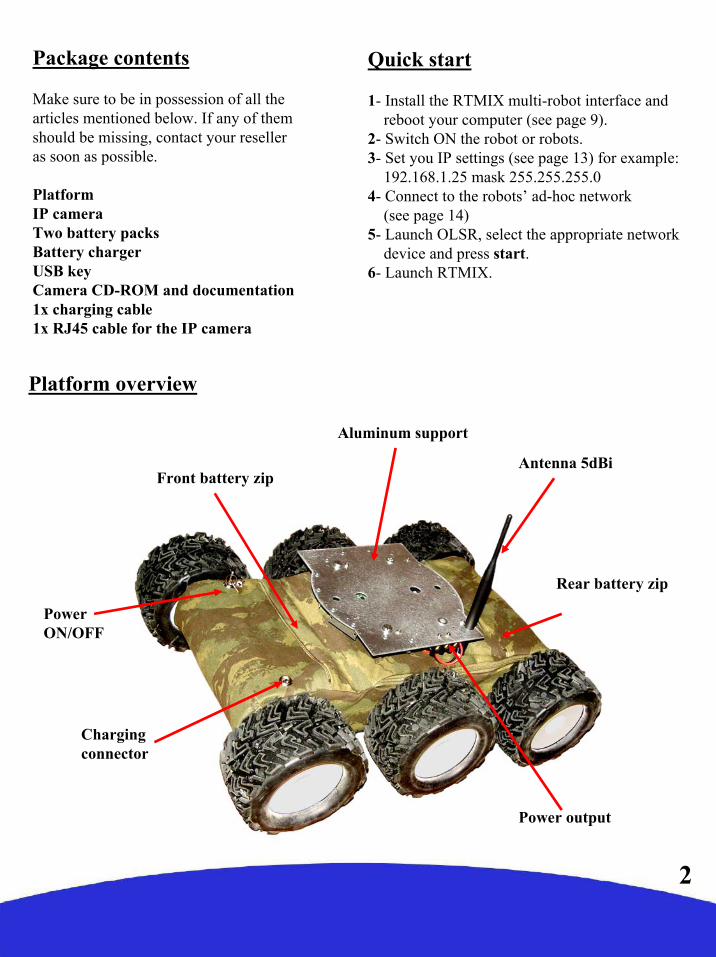
Package contents
Make sure to be in possession of all the articles mentioned below. If any of them should be missing, contact your reseller as soon as possible.
PlatformIP cameraTwo battery packsBattery chargerUSB keyCamera CD-ROM and documentation1x charging cable1x RJ45 cable for the IP camera
Platform overview
2
Front battery zip
Chargingconnector
Power ON/OFF
Rear battery zip
Antenna 5dBi
Power output
Aluminum support
Quick start
1- Install the RTMIX multi-robot interface andreboot your computer (see page 9).
2- Switch ON the robot or robots.3- Set you IP settings (see page 13) for example:
192.168.1.25 mask 255.255.255.04- Connect to the robots’ ad-hoc network
(see page 14)5- Launch OLSR, select the appropriate network
device and press start.6- Launch RTMIX.
3
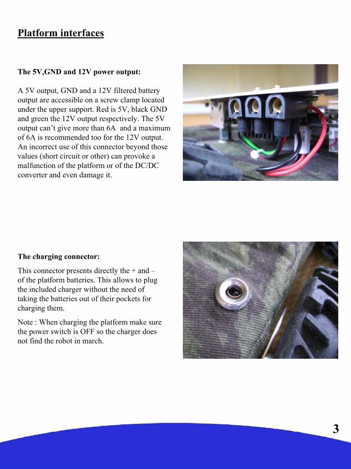
Platform interfaces
The 5V,GND and 12V power output:
A 5V output, GND and a 12V filtered battery output are accessible on a screw clamp located under the upper support. Red is 5V, black GND and green the 12V output respectively. The 5V output can’t give more than 6A and a maximum of 6A is recommended too for the 12V output. An incorrect use of this connector beyond those values (short circuit or other) can provoke a malfunction of the platform or of the DC/DC converter and even damage it.
The charging connector:
This connector presents directly the + and –of the platform batteries. This allows to plug the included charger without the need of taking the batteries out of their pockets for charging them.
Note : When charging the platform make sure the power switch is OFF so the charger does not find the robot in march.

4
The ON/OFF switch:
The platform is switched ON and OFF by turning a key. In order to avoid the possible loss, the key should remain attached to the platform at all times.
RS232 connector:
The low level motor control of the platform is to be accessed through this connector using a certain communication protocol (see the RS232 protocol section).
The antenna connector:
This is the wi-fi antenna connector. Pass the antenna through the upper support hole and screw it carefully on the connector till the end.

Insertion:
1- Open the zip.2- Find the connector and plug the battery pack. 3- Introduce the connector and battery cables
inside the pocket and push them at a side. 4- Introduce the battery diagonally into the
pocket with the cables on the down part. Thebattery pack on the front has to be insertedfrom right to left, while the battery pack on therear has to be inserted from left to right (seephoto).
5
Battery installation
The robot gets its power from two battery packs with 5 Ni-MH cells each, with a capacity of 10000 mAH and a total nominal voltage of 12V. Located on the front and rear parts of the platform, their location into “pockets” has been thought to facilitate their removal and replacement. During normal operation the battery packs remain inside the robot and need only to be taken out in rare occasions.
6
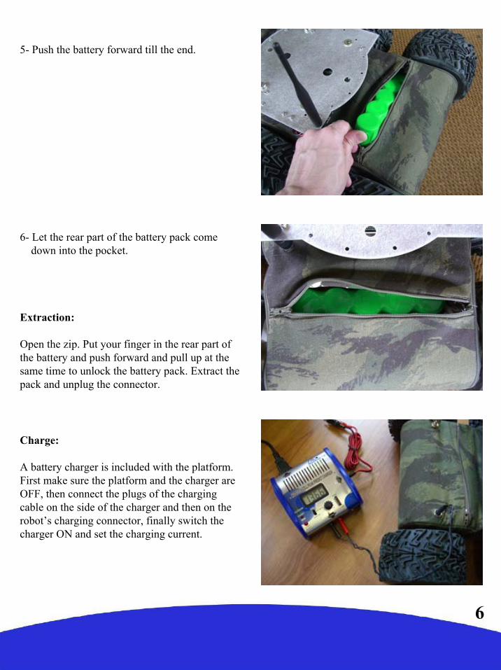
5- Push the battery forward till the end.
6- Let the rear part of the battery pack comedown into the pocket.
Extraction:
Open the zip. Put your finger in the rear part of the battery and push forward and pull up at the same time to unlock the battery pack. Extract the pack and unplug the connector.
Charge:
A battery charger is included with the platform. First make sure the platform and the charger are OFF, then connect the plugs of the charging cable on the side of the charger and then on the robot’s charging connector, finally switch the charger ON and set the charging current.

Computer and camera installation
The platform is sold with an IP camera and an embedded computer which model can vary depending of the version. Those are independent elements from the platform which can be replaced by any other model. For more information about your particular camera and embedded computer please refer to their respective manuals included in the USB key included with the robot. The top aluminum support of the platform has been thought for the fixation of those and other user components.
Their installation takes place as follows:
Unscrew the upper aluminum support:
Fix the embedded computer on the down part of the support :
7
8
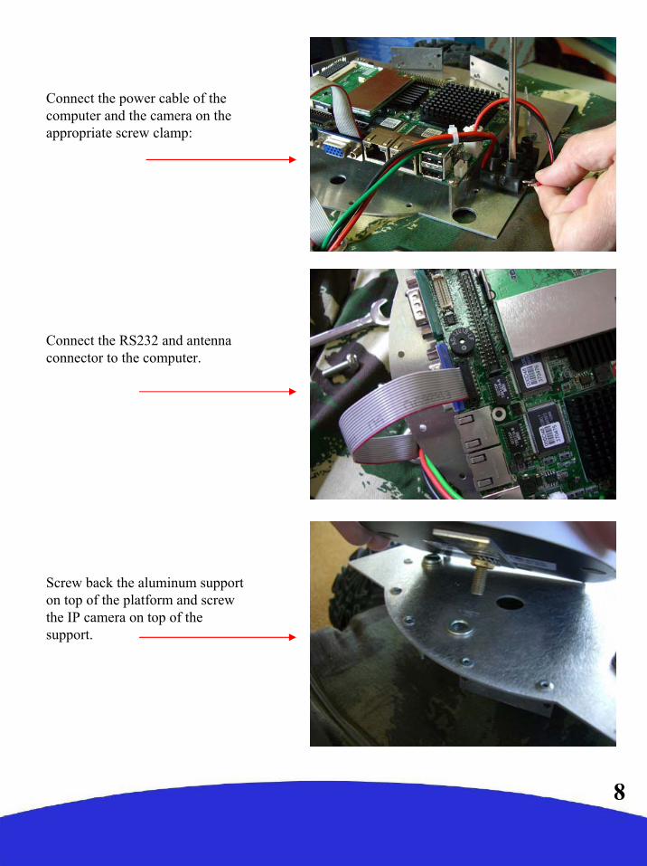
Connect the power cable of the computer and the camera on the appropriate screw clamp:
Connect the RS232 and antennaconnector to the computer.
Screw back the aluminum support on top of the platform and screwthe IP camera on top of thesupport.

9
RTMIX multi-robot interface
Installation:
1- Unpack the zip file.2- Double-click on Setup.3- Unselect from the program list those you may already have
installed on your computer.4- Click on the « install » button.5- When asked to reboot your computer always say « no ».6- Once installation is done, create a folder « rtmix » in the web
shared folder of the web server installed on your computer.If you have followed the standard installation this would be« C:/wamp/www/ »
10- Copy the containt of «C:/Program Files/RTMIX/monsite/»into the «rtmix» folder you just created, ex:«C:/wamp/www/rtmix/»
11- Reboot your computer.
10
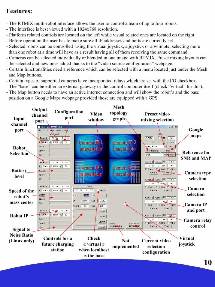
Features:
- The RTMIX multi-robot interface allows the user to control a team of up to four robots.- The interface is best viewed with a 1024x768 resolution. - Platform related controls are located on the left while visual related ones are located on the right.- Before operation the user has to make sure all IP addresses and ports are correctly set. - Selected robots can be controlled using the virtual joystick, a joystick or a wiimote, selecting more
than one robot at a time will have as a result having all of them receiving the same command. - Cameras can be selected individually or blended in one image with RTMIX. Preset mixing layouts can
be selected and new ones added thanks to the “video source configuration” webpage. - Certain functionalities need a reference which can be selected with a menu located just under the Mesh
and Map buttons.- Certain types of supported cameras have incorporated relays which are set with the I/O checkbox.- The “base” can be either an external gateway or the control computer itself (check “virtual” for this).- The Map button needs to have an active internet connection and will show the robot’s and the base position on a Google Maps webpage provided those are equipped with a GPS.
Signal to Noise Ratio (Linux only)
Speed of the robot’s
mass center
Batterylevel
Robot Selection
Camera selection
Reference for SNR and MAP
Preset videomixing selection
Robot IP
Input channel
port
Output channel
port
Not implemented
Current video selection
configuration
Camera type selection
Controls for a future charging
station
Camera IP and port
Virtualjoystick
Videowindow
Googlemaps
Meshtopology
graph
Camera relaycontrol
Configuration port
Check« virtual »
when localhostis the base

11
The input menu allows tochoose between fourmodes of controlling therobots. Those are:- mouse (virtual joystick)- joystick- wiimote- autojump (virtual joystick)This is a mode where the robotadvances a certain distance witha set speed and radius.
The view menu allows tochoose between two modes ofpresentation:- Normal view (default)- Fullscreen view This is a mode where the videowindows covers the whole screen.It is particularly useful when usingconfiguration webpages or drivingthe robots.
The markers menu allows fornow only to take snapshots ofthe current video window andto place a marker on the map atthe location it was taken. Thesnapshot can then be seen byclicking on the marker.
Program menu:

12
Configuration:
The configuration webpage is accessible clicking on the “video source configuration” button when RTMIX is selected. The video mixing capabilities were originally designed to be embedded in larger robots and controlled remotely. They were only later adapted to the u-trooper system, this is the reason why some options such as the analog cameras are not applicable. To create a custom layout to be added to the interface menu do the following:
- Select the cameras and sensors to be displayed.- Drag the cameras and the sensors at the desired location.- Set the size, opacity and z-order of the different cameras.- Press the save button and introduce a name.
Video windows can be dragged around in order to precisely position them
on the screen
Scroll bar settingthe size of theselected video
window
Sensor input enable/disable
Reset Save config
Scroll bar settingthe transparency
of the selectedvideo window Not
used
8x analog cameras (not used with u-troopers)
4x network cameras z-order
Not used

Connecting to the robot:
Configuring your ethernet/wireless adapter:
By default, the robot has been pre-configured with certain IP addresses. Before connecting to the robot you may need to adjust the IP settings of the network adapter of your computer. Make sure all the devices in a same network having to communicate with the robot have the same class of address.To adjust the TCP/IP settings of the network adapter:
1- Right-click on My Network Places in the Startmenu, then select Properties from the pop-up menu. The Network and Dial-up Connections window appears.(Fig1)
2 - Create a network bridge between your interfaces or else disable all the network adapters except the one you want to use for connecting to the robot (Ethernet or Wi-Fi). Right-click the network adapter, then select Properties from the pop-up menu. (in Fig1)
3 - Double-click the Internet Protocol (TCP/IP)item to display the Internet Protocol (TCP/IP) Properties window. (in Fig2)
4 - Check the Use the following IP address option, then enter the IP address for the network adapter. Set IP address depending on the case : (in Fig3)
If you are connecting to a robot under Linux with a cable directly to an ethernet port, that is to the LAN, then enter 192.168.0.x (x can be any number between 1 and 254 except 250 and those used by the CPU and the camera of the robot). For example, a Wifibot Serial Number: S/N Y-AXX will have as IP for the CPU 192.168.0.1XX and 192.168.0.XX for the camera, those number are therefore not available. Set the Subnet Mask to 255.255.255.0and leave Default gateway and DNS empty.
If you are connecting to a robot under windows or wirelessly under Linux, that is to the WLAN, then enter 192.168.1.x (x can be any number between 1 and 254 except those used by robots or other devices). For example, a Wifibot Serial Number: S/N Y-AXX will have as IP 192.168.1.1XX. Set the Subnet Mask to 255.255.255.05 - Click OK when finished.
Fig 1
Fig 2
Fig 3
13
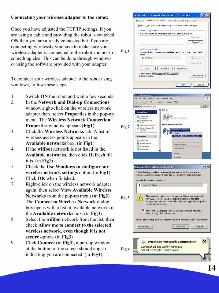
Connecting your wireless adapter to the robot:
Once you have adjusted the TCP/IP settings, if you are using a cable and providing the robot is switchedON then you are already connected but if you areconnecting wirelessly you have to make sure yourwireless adapter is connected to the robot and not tosomething else. This can be done through windowsor using the software provided with your adapter.
To connect your wireless adapter to the robot usingwindows, follow these steps:
1. Switch ON the robot and wait a few seconds.2. In the Network and Dial-up Connections
window,right-click on the wireless networkadapter,then select Properties in the pop-up menu. The Wireless Network Connection Properties window appears.(Fig1)
3. Click the Wireless Networks tab. A list of wireless access points appears in the Available networks box. (in Fig1)
4. If the wifibot network is not listed in the Available networks, then click Refresh till it is. (in Fig1)
5. Check the Use Windows to configure my wireless network settings option.(in Fig1)
6. Click OK when finished. 7. Right-click on the wireless network adapter
again, then select View Available Wireless Networks from the pop-up menu (in Fig2). The Connect to Wireless Network dialog box opens with a list of available networks in the Available networks box. (in Fig3)
8. Select the wifibot network from the list, then check Allow me to connect to the selected wireless network, even though it is not secure option. (in Fig3)
9. Click Connect (in Fig3), a pop-up window at the bottom of the screen should appear indicating you are connected. (in Fig4)
Fig 1
Fig 2
Fig 3
Fig 4
14

Networking
Network architecture:
In the micro-trooper, the embedded CPU works as a gateway between the internal wired LAN and the external wifi WLAN. The CPU has at least one ethernet card andone wireless card that form two separate networks (LAN/WLAN).The LAN and theWLAN should have in general a differentaddress class and therefore data needs to be routed between them. Depending if you have chosen a robot under Windows or Linux the problem of connecting the two networks has been solved differently. Under Windows this has been done by configuring a bridge between the network interfaces, by doing so the robot’s CPU appears to have a unique network interface and uses one single IP address. Under Linux, the interconnection is done through Dynamic NAT (Network Address Translation) and the CPU uses two different IP adresses, one for the internal LAN and one for the WLAN. In both cases, all local components of the robots such the IP camera will have their own IP address within the LAN, but when it comes to accessing them from the WLAN the method will differ. Under Windows as there is in practice no distinction between the WLAN and the LAN, every internal component will be reached using its own IP address (seeFig1). Under Linux, only the robot’s CPU WLAN IP address can be seen and any internal network element will have to be reached using this single IP. In order to be able to access the separate devices using a single IP, we will need to assign to each of them a separate port (see Fig2). This will require to configure the CPU with the proper routing table (see pag 18).
Fig 1
Fig 2
15

WLAN modes:
Let’s have here a quick overview of the different modes Wi-Fi adapters can be configured :
-Infrastructure Master (Access Point)-Infrastructure Managed (Adapter/Bridge)-Ad-hoc without routing algorithm-Ad-hoc with the OLSR routing algorithm (Mesh Networking)
In infrastructure mode we have a master/slave structure where all the data is centralized in one device called access point (server/master) to which different adapters (clients/slaves/managed) connect. A client cannot talk directly to another but has to pass by the access point which will forward the data to the destination. Several access points can beconnected together with cables extending in this waythe zone covered by the wireless network. This is the most common setup for a Wi-Fi network (see Fig1).
In ad-hoc mode we do not have any central management, each client can talk directly to the other. This mode works fine for networks with few elements. Without any routing algorithm, each element needs to have a direct radio link with the others in order to communicate, no data will be forwarded (see Fig2). If a routing algorithm such as OLSR is added, you obtain a self-organizing mesh network in which message forwarding is possible wirelessly between different nodes, connecting in this way devices which are not within direct radio range (see Fig3). This allows to extend the zone covered without the need of any cable.The network is completely dynamic, routing tables are rewritten automatically and dynamically as the network changes. If a new OLSR enabled device appears, it will be automatically detected and merged to the routing tables of each node. This is especially useful for mobile networks that can change over time like for example in a multi-robot application.
16
Fig 1
Fig 2
Fig 3

17
Robot under Windows XP
By default all robots come already configured and readyto work. Information is given here for those users willingto make changes in the network configuration. When working under Windows the micro-trooper canonly be configured in the managed and ad-hoc modes.For configuring the IP settings in managed mode orconnecting the micro-trooper to an AP or an alreadycreated ad-hoc network please follow the steps detailedin the “connecting to the robot” section. In addition tothose steps, it is recommended to create from the robotitself the ad-hoc network to be used:
1. Open Network Connections, Select your Wirelesscard right click on it and select Properties.
2. Click the Wireless Networks tab.3. Enable Use Microsoft Windows to configure my
wireless network settings4. Click Add…5. For Network name (SSID) type: wifibot6. For Data encryption select Disabled7. Enable This a computer-to-computer (ad hoc)
network8. Click Ok to close the ‘Wireless network
properties’ window9. Click Ok to close the ‘Wireless Network
Connection Properties’ window10. Using your test computer wireless adapter, view
the available wireless networks, check the list andvalidate that you can see your newly configuredwifibot network. If it is configured, try toconnect to it. If you cannot find your new networkverify the settings are correct.
Network configuration
Robot under Linux
Under Linux all modes are possible, we will see here the different parameters involved in the configuration of the robot. There are 3 important configuration files we need to manage in the robot:
../etc/network/interfaces
../etc/nylon/interfaces.conf
../etc/rc2.d/S31wifibot
These files can either be edited outside the robot and then transferred or directly edited on the robot.
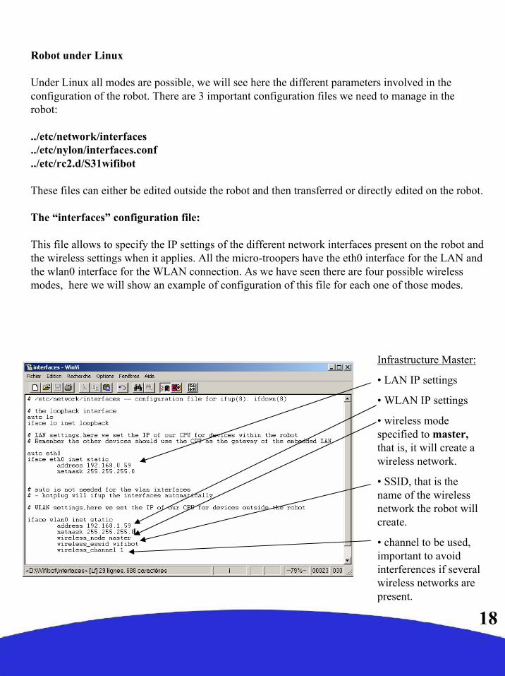
The “interfaces” configuration file:
This file allows to specify the IP settings of the different network interfaces present on the robot and the wireless settings when it applies. All the micro-troopers have the eth0 interface for the LAN and the wlan0 interface for the WLAN connection. As we have seen there are four possible wireless modes, here we will show an example of configuration of this file for each one of those modes.
18
Infrastructure Master:
• LAN IP settings
• WLAN IP settings
• wireless mode specified to master, that is, it will create a wireless network.
• SSID, that is thename of the wirelessnetwork the robot willcreate.
• channel to be used, important to avoidinterferences if severalwireless networks are present.
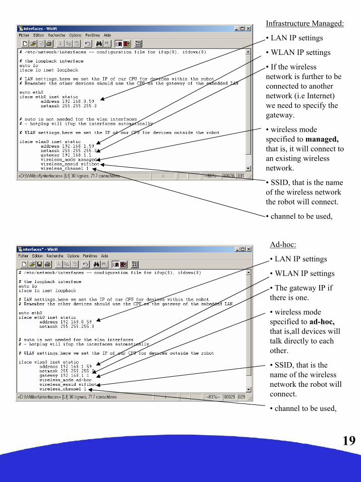
Ad-hoc:
• LAN IP settings
• WLAN IP settings
• The gateway IP if there is one.
• wireless mode specified to ad-hoc, that is,all devices willtalk directly to eachother.
• SSID, that is thename of the wirelessnetwork the robot willconnect.
• channel to be used,
Infrastructure Managed:
• LAN IP settings
• WLAN IP settings
• If the wirelessnetwork is further to beconnected to anothernetwork (i.e Internet) we need to specify thegateway.
• wireless mode specified to managed, that is, it will connect to an existing wirelessnetwork.
• SSID, that is the nameof the wireless network the robot will connect.
• channel to be used,
19

Ad-hoc + OLSR:
• LAN IP settings
• WLAN IP settings
• In mesh mode weneed to specify thebroadcast address.
• The gateway IP if there is one.
• wireless mode specified to ad-hoc (mesh is built over ad-hoc).
• SSID, that is thename of the meshnetwork the robot willconnect.
• channel to be used,
• RTS parameterneeded in mesh mode.
20
The “interfaces.conf” configuration file:
This file is very simple, all it does is to indicate what interfaces we have and if the wireless ones will work as standard Wi-Fi or doing Mesh networking.
Normal Wi-Fi:
• We specify here thenetwork interfaces.
• We then specify thatthe wireless interface will work as a normal Wi-Fi device.
Mesh Networking:
• We specify here thenetwork interfaces.
• We then specify thatthe wireless interface will make use of OLSR and work within a meshnetwork.

21
The “S31wifibot” configuration file:
This is the last step of configuration, we will first specify the routing tables of the NAT address translation, this is needed to make the embedded devices visible from outside therobot. Then we set the commands to launch the control server and some computer dependent drivers at boot time.
Information about IPTABLES/NAT can be found at http://www.netfilter.org/
We use « iptables »for seeting the NAT
The interface weare « NATting »
The WLAN interface IP and ports we willconnect to from outside.
The LAN deviceIP and ports wewant to reach(i.e the camera)
Start the control server to wait for connections
Creates the interface in order to getaccess the I²C bus
Installs theI²C driver
IMPORTANT NOTE!!!!: When editing the configuration files under windows, use the “WinVi32.exe” text editor ONLY, it is included in the USB key at data\software\WinVi32\It is important to use it to respect the Linux format, specially when editing configuration files. Another option is to edit the files directly on the CPU under Linux with the installed “vi” editor, check http://www.linuxfibel.de/vi.htm for more information.

22
Remote access to the desktop of a robotworking under Windows XP:
When working with the micro-trooper, it is alwayspossible to attach a screen, a mouse and a keyboarddirectly into the embedded computer but it is oftenmore convenient to have access to the robotremotely over the network. If the robot works underWindows follow these steps:
1- Click Start, point to All Programs, and thenpoint to Accessories.
2- In the Accessories menu,point to communicationsand then click Remote Desktop Connection.
3- In the Computer box, type the IP address or thename of the robot you want to connect to (Fig 1).
4- Click Connect.5- When the Log On to Windows dialog box appears
type root as the user name and wifibot as thepassword, and then click OK (Fig 2).
The Remote Desktop window opens, and you see thedesktop settings, files, and programs that are on therobot. Your robot remains locked, and nobody canaccess it without a password. In addition, no one willbe able to see the work you are doing remotely.
To end your Remote Desktop session:
1. Click Start, and then click Log Off at the bottomof the Start menu.
2. When prompted, click Log Off (Fig 3).
Fig 1
Fig 2
Fig 3
Remote access

Remote access to the command line of a robotworking under Linux :
To remotely log into the robot’s Linux operatingsystem we will make use of a protocol called SSH(Secure Shell) which facilitates encryptedcommunication across networks. This requires aSSH client program. Whichever the SSH client youuse, the procedure is similar:
1. Open the SSH client.2. Enter the CPU IP address (the default port
is 22) and then start the connection.3. The first time a connection is established,
the program will ask for confirmation.4. Enter login: root.5. Enter password: wifibot
For your convenience the USB key includes a freeSSH client you can find in data\software\putty\
Connect to the robot in the following steps:
1 - Enter the IP address here.
2 - Check the SSHoption.
3 - Click Open to start the connection.
4 - Confirm the connection.
5 - Enter login: root
6 - Enter password: wifibot
23
24
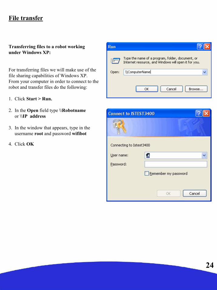
Transferring files to a robot workingunder Windows XP:
For transferring files we will make use of thefile sharing capabilities of Windows XP.From your computer in order to connect to therobot and transfer files do the following:
1. Click Start > Run.
2. In the Open field type \\Robotnameor \\IP address
3. In the window that appears, type in theusername root and password wifibot
4. Click OK
File transfer
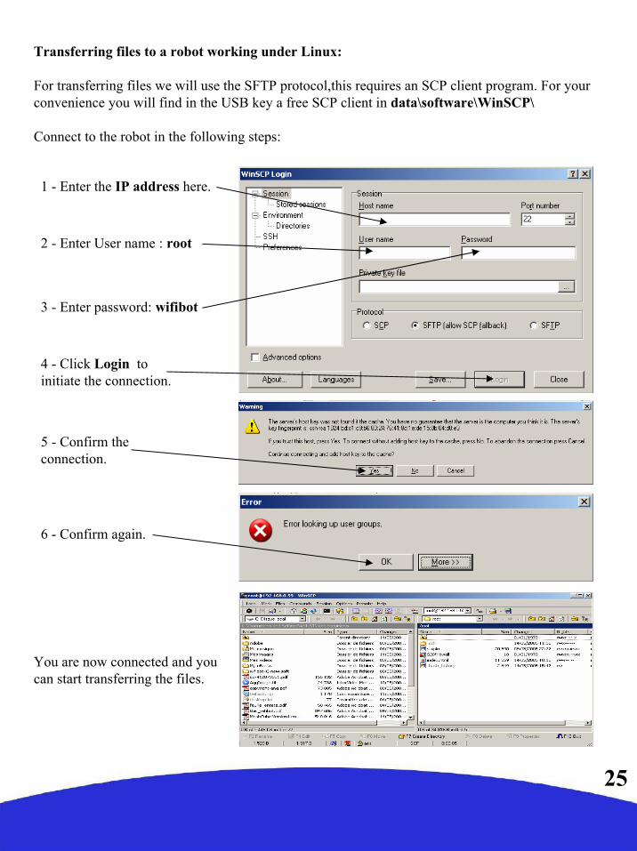
Transferring files to a robot working under Linux:
For transferring files we will use the SFTP protocol,this requires an SCP client program. For your convenience you will find in the USB key a free SCP client in data\software\WinSCP\
Connect to the robot in the following steps:
1 - Enter the IP address here.
2 - Enter User name : root
3 - Enter password: wifibot
4 - Click Login to initiate the connection.
5 - Confirm the connection.
6 - Confirm again.
You are now connected and you can start transferring the files.
25

Communication protocols
The micro-trooper has been thought as an open robotic tool and as such it allows the user to have an absolute control over the higher layers. The user can work at two different levels with a micro-trooper, on one side it is possible to program on the embedded computer your own autonomous behaviors and on the other you can consider the robot as a network peripheral and program all processes on a remote computer to finally only send the final commands to the robot or robots to perform.
The only level that is not accessible to the user is the microcontroller that takes in charge the motor control. The programmer will have therefore to stick with the established communication protocol between the embedded computer and the microcontroller. Users are free though to make use of the existing protocol between the embedded computer and the provided control interface for their own projects or to create a new one altogether that would suit better their application needs.
The computer-microcontroller protocol:
The embedded computer communicates with the microcontroller at 19200 baud through a RS232 link on COM2. Parameters are 8 data bits, no parity and one stop bit. When receiving no data the robot will automatically stop, this means a permanent communication stream has to be established in order to keep the robot moving. For every byte sent from the computer, the microcontroller sends one byte of raw sensor data in answer. This exchange of information takes place in cycles of 7 bytes as follows:
26
Bytes sent: 255 RIGHT LEFT NULL NULL NULL NULL
Bytes received: RIGHT LEFT IR1 IR2 IR3 IR4 BATT
Reset byte
Rightspeed
Leftspeed
Nullbytes
#tics/41ms IR sensorsif present
(clockwise)
Batterylevel
#tics/41ms
27
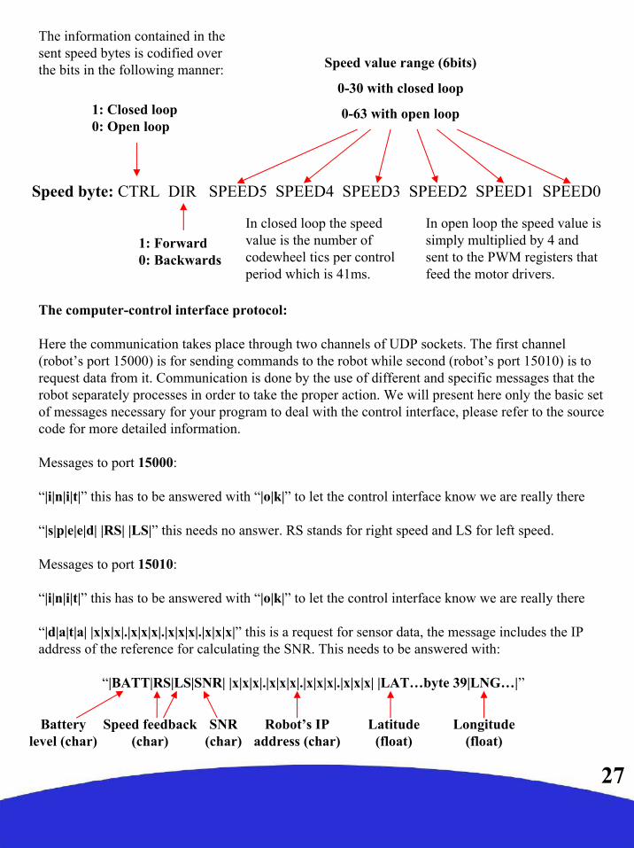
The information contained in the sent speed bytes is codified over the bits in the following manner:
Speed byte: CTRL DIR SPEED5 SPEED4 SPEED3 SPEED2 SPEED1 SPEED0
1: Closed loop0: Open loop
1: Forward0: Backwards
Speed value range (6bits)
0-30 with closed loop
0-63 with open loop
In closed loop the speed value is the number of codewheel tics per control period which is 41ms.
In open loop the speed value is simply multiplied by 4 and sent to the PWM registers that feed the motor drivers.
The computer-control interface protocol:
Here the communication takes place through two channels of UDP sockets. The first channel (robot’s port 15000) is for sending commands to the robot while second (robot’s port 15010) is to request data from it. Communication is done by the use of different and specific messages that the robot separately processes in order to take the proper action. We will present here only the basic set of messages necessary for your program to deal with the control interface, please refer to the source code for more detailed information.
Messages to port 15000:
“|i|n|i|t|” this has to be answered with “|o|k|” to let the control interface know we are really there
“|s|p|e|e|d| |RS| |LS|” this needs no answer. RS stands for right speed and LS for left speed.
Messages to port 15010:
“|i|n|i|t|” this has to be answered with “|o|k|” to let the control interface know we are really there
“|d|a|t|a| |x|x|x|.|x|x|x|.|x|x|x|.|x|x|x|” this is a request for sensor data, the message includes the IP address of the reference for calculating the SNR. This needs to be answered with:
“|BATT|RS|LS|SNR| |x|x|x|.|x|x|x|.|x|x|x|.|x|x|x| |LAT…byte 39|LNG…|”
Speed feedback (char)
Batterylevel (char)
SNR (char)
Robot’s IP address (char)
Latitude (float)
Longitude (float)

Documentation:
In this folder you will find the original documentation of the platform (this file), the embeddedcomputer and the camera.
Software:
This folder contains the RTMIX remote multi-robot control software installation program, a copy of the robot’s embedded server, as well as several tools necessary to manage the robot.
Code Samples:
Here you can find the source code of the robot’s server for Windows and Linux as well as samples for the programming of remote control applications on computers under both Windows and Linux.
The USB key
The USB key included with the robot has multiple purposes. It is the support for the operative system, it contains the documentation and sample programs for the robot and works as a security key. Only the “data” folder is accessible to the user when using it on the robot. Its root contains three folders and the current robot’s program that will be executed at startup (wifibot_server.exe). This executable can be freely replaced by the user with his or her own custom program giving him or her absolute control over the robot. The folders are the following:
28