wind turbine operation & maintenance based on … turbine operation & maintenance based on...
TRANSCRIPT

April 2003 ECN-C--03-047
Wind Turbine Operation & Maintenancebased on Condition Monitoring
WT-Ω
Final report
T.W. Verbruggen

2 ECN-C--03-047
Acknowledgement
This report is part of the project entitled WT_Ω (WT_OMEGA = Wind Turbine Operation andMaintenance based on Condition Monitoring) which has been carried out in co-operation withLagerwey the WindMaster, Siemens Nederland, and SKF.
The work was partly financed by NOVEM, and partly by ECN Wind Energy.
ECN project number : 7.4028Novem contract number : 224.321-9960

ECN-C--03-047 3
CONTENTS
SUMMARY 5
1. INTRODUCTION 71.1 Background 71.2 Objectives 7
2. LITERATURE STUDY (SUMMARY) 112.1 Condition Monitoring Techniques 112.1.1 Vibration Analysis 112.1.2 Oil analysis 122.1.3 Thermography 122.1.4 Physical condition of materials 122.1.5 Strain measurement 132.1.6 Acoustic monitoring 132.1.7 Electrical effects 132.1.8 Process parameters 132.1.9 Performance monitoring 132.2 Possibilities of application in wind turbines 142.2.1 Rotor14
2.2.1.1 BLADES14
2.2.1.2 PITCH MECHANISM 142.2.2 Nacelle 14
2.2.2.1 GEARBOX AND MAIN BEARING 14
2.2.2.2 GENERATOR 15
2.2.2.3 HYDRAULIC SYSTEM 15
2.2.2.4 YAW SYSTEM 152.3 Economical Aspects 152.4 Conclusions 16
3. SELECTED SUB-SYSTEMS, COMPONENTS AND CM-TECHNIQUES 193.1 Global condition monitoring techniques 193.2 Pitch mechanism 193.3 Gear box 213.4 Main bearing 213.5 Sound registration 223.6 Blade monitoring 22
4. INSTRUMENTATION OF THE LAGERWEY 50/750 23
5. INSTRUMENTATION OF THE ENRON 1,5 S 25
6. CONCLUSIONS 29
7. REFERENCES 31
APPENDIX A: MEASUREMENT AND INSTRUMENTATION PLAN OF THELAGERWEY 50/750 33
APPENDIX B: MEASUREMENT AND INSTRUMENTATION PLAN OF THE ENRON1,5S TURBINE 37

4 ECN-C--03-047

ECN-C--03-047 5
SUMMARY
In 1999, ECN has taken the initiative to investigate the further application of conditionmonitoring for wind turbines. With financial support from NOVEM, ECN has carried out theproject WT-Ω.
The project included three parts, being:1. A literature study on available condition monitoring techniques, also including a selection
of techniques which has added value for wind turbines.2. Instrumentation of a turbine and demonstration of some of the selected condition
monitoring techniques.3. Identification of new areas for further development such as new sensors, algorithms and
system integration.
This document contains a summary of the literature survey and an overview of the work that hasbeen carried out to instrument the Lagerwey LW50/750 and the Enron 1.5S turbines.
The literature study has been carried out and gives insight in the application of conditionmonitoring techniques and the possibilities, economically as well as technically. The mostinteresting areas have been identified, taking into account the state of the art of the monitoringtechniques.
For the second part of the project, a prototype of the Lagerwey the Windmaster LW 50/750 wasselected. Great advantage of this turbine was that instrumentation for load measurements wasalready available for certification. So for the condition monitoring project only additionalmeasurements with respect to process parameters had to be added. Critical subsystems, whereadded value of condition monitoring can be expected are the pitch system and the main bearing.
Important disadvantage of this type of turbine is the absence of a gearbox, which is normallyconsidered as a critical component where important costs reduction can be achieved when faultsare detected in an early stage. Also the main bearing is not representative for common windturbine designs.
For a development project on condition monitoring, steady state operation for a long period isnecessary in order to be able to recognise trend in characteristic signals. The prototype of theLagerwey was prone to frequent replacement of components and control software. Becausesteady state operation could not be assured, the measurement program has been cancelled.
In order to carry out the second phase of the project, another turbine was selected to performmeasurements. The ENRON 1,5s turbine, owned by Siemens and located in Zoetermeer,appeared to be suitable for the project because the main objective is electricity production andthe design can be considered as representative. The drive train is conventional, including agearbox, it operates with variable speed and it has three independent electrical pitch systems.Besides that, Siemens was also very interested in the project from the point of view ofmaintenance for off shore wind application.
Unfortunately, the time delay in the project caused by the non-availability of the Lagerweyturbine, the time needed for instrumentation and consultation for the Lagerwey turbine as wellas for the Enron turbine appeared to be so time consuming that the third part could not becarried out. The measurement system for the Enron turbine has been implemented and will beused in a successive project.
Important spin-off of the project is the development of fibre optic measurement technology.This techniques offers large potential with respect to blade condition monitoring and loadreduction. A first measurement system has been installed in the DOWEC turbine for load

6 ECN-C--03-047
measurements. Further development should result in off-the-shelf sensors and instrumentation,which can easily be integrated in the wind turbine control system.
From the experience gained during the project it can be concluded that:• There is a rapid growing interest for condition monitoring for wind turbines.• Systems, based on vibration analysis, developed for other branches of industry, are available.• The effectiveness of standard condition monitoring systems for wind turbines is not yet
demonstrated and not yet evident.• Besides the standard condition monitoring techniques, there are also opportunities for more
specialised provisions which can be implemented in the wind turbine control system.• The activities for adaptation and verification of standard monitoring techniques for wind
turbines as well as development of specialised functions require will require a long term.• A measurement facility, which is available for a long period and which is provided with
flexible communication provisions is essential for development and improvement ofcondition monitoring systems.

ECN-C--03-047 7
1. INTRODUCTION
1.1 Background
The operational costs of offshore wind turbines that are presently commercially available, seemtoo high to make offshore wind projects economically viable. For offshore wind, the costs forO&M (Operation and Maintenance) are estimated in the order of 30 to 35 % of the Costs ofElectricity. Rough 25 to 35% is related to preventive maintenance and 65 to 75% to correctivemaintenance (note that onshore this ratio is approximately 1:1). The revenue losses for offshorewind turbines are estimated in the same order as the direct costs for repair whereas for onshoreprojects the revenue losses are negligible [7], [8], [9].
One of the approaches to reduce the cost for corrective maintenance is the application ofcondition monitoring for early failure detection. If failures can be detected at an early stage, theconsequence damage can be less so the repair will be less expensive. Offshore wind turbineshowever, will benefit the most from the fact that with early failure detection, repairs can bebetter planned. This will lead to shorter downtimes and less revenue losses.
The application of condition monitoring has grown considerably in the last decade in severalbranches of industry. The interest from the wind turbine industry and operators is alsoincreasing for the reasons mentioned above. Because of small financial margins in the windturbine branch, the relatively small production losses, the minor effects on the electricitynetwork (a wind turbine is operating stand-alone), and the easy access, the application remainedlimited to some experimental projects. Additionally, most components have been designed forthe lifetime of the turbine, which implies that degradation leading to replacement, is expectednot to occur.
At present, with the increasing installed power of the wind turbines, the application of off shorewind turbines and major problems with gearboxes, the necessity of condition monitoring cannotbe neglected any longer. Some components, although designed for the turbine lifetime, failearlier than expected. This is emphasised by the approach of insurance companies in Germany,which simply require application of monitoring provisions. Otherwise, expensive preventivereplacements or inspections should be carried out periodically. Also the development of specialpurpose instrumentation for wind turbines result in more or less off the shelf systems for areasonable price.
1.2 Objectives
In 1999, ECN has taken initiatives to further investigate the applicability of conditionmonitoring for wind turbines. With financial support from NOVEM, ECN has carried out theproject WT_Ω (WT_OMEGA = Wind Turbine Operation and Maintenance based on ConditionMonitoring) from 2000 to 2003. The objectives of the project were threefold:1. making an inventory of the available condition monitoring techniques and selecting a set
which has added value for wind turbines;2. to instrument a wind turbine and demonstrate some of the selected condition monitoring
techniques;3. identifying areas for further development, e.g. new sensors, algorithms for data analysis ,or
integration of the systems in the turbine and wind farm controller.

8 ECN-C--03-047
For objective 1, a literature survey has been carried out and reported in [1]. A summary of thisstudy can be found in Chapter 2. It gives insight in the application of condition monitoringtechniques and the possibilities, economically as well as technically. A trade off has beenperformed to identify the most interesting application areas, taking into account the state of theart of the monitoring techniques. Some techniques seem very promising on a long term, whichrequires a separate development with related risks. Fibre optics measurement technology is sucha technique. (Note that the development of fibre optic measurement techniques is outside thescope of this project and will not be discussed further on. Details can be read in [2].) Thecondition monitoring systems and techniques that seem promising for optimising themaintenance procedures of wind farms have been summarised in Chapter 3.
For objective 2, a prototype of the Lagerwey the WindMaster LW 50/750 turbine was selected.The LW 50/750 is a direct drive turbine with a rated power of 750 kW, independent electro-mechanical blade pitch mechanisms, and variable speed. Based on the literature study, ameasurement and instrumentation plan were made, with the aim to obtain measurement data forfurther signal analysis. This turbine was selected because Lagerwey the Windmaster wasalready a partner in the project, and this turbine was already instrumented for loadmeasurements. Only additional instrumentation had to be added at relatively low costs.
After the turbine was fully instrumented, it appeared that the consequences of applyingcondition monitoring systems to a prototype were underestimated. The blades were replacedseveral times during the project, the parameter settings changed regularly and the back-to-backconverter was subject of continuous development. For condition monitoring experiments, astable configuration for a longer period is very important. The start of the measurementcampaign was postponed several times, waiting for a configuration that remained unchanged fora period of at least 3 months. Unfortunately, the required stable configuration could not beassured by Lagerwey the Windmaster. After waiting for almost 1 year, but without obtainingvaluable measured data, the project team decided to cancel the measurements. The measurementand instrumentation plan and the experiences with the LW 50/750 turbine are described inChapter 4 and Annex A.
After consultation with Novem, the project team decided to continue with the conditionmonitoring experiments, however it was realised that within the constraints of the project(mainly limited time and budget) the initial project objectives could not be fully met. First of all,another project partner and another turbine had to be found. Secondly, the new turbine had to beinstrumented again, and finally a measurement period of at least 3 to 6 months was necessary.Within the constraints of the project, only the instrumentation of a new turbine was feasible.Finalising the measurements and collecting relevant data was not possible. To make sure thatthe condition monitoring experiments could be finished satisfactorily, a new project wasdefined. It was decided to initiate a new European project on condition monitoring for offshorewind farms (CONMOW) [6]. This new project should be regarded as the “successor” of WT_Ω.
The new project partner was Siemens Nederland N.V.. Siemens has shown their interest in theproject for some time, and offered the possibility to use the Enron 1.5S turbine in Zoetermeerfor condition monitoring measurements. The Enron 1.5 S turbine is more suited for conditionmonitoring experiments since it is equipped with a gearbox, and a high speed generator. TheEnron turbine is more representative for the first generation offshore turbines than the LW50/750 turbine. Due to technical and contractual matters among the partners and GeneralElectric (formerly Enron Wind), it took about a year before the instrumentation of this turbinestarted. By the end of the project, the Enron 1.5 S turbine was instrumented to a large extent andready for executing the CONMOW project. The instrumentation is very flexible, andincorporates the possibility to install different condition monitoring techniques for developmentand evaluation. This is described in Chapter 5.

ECN-C--03-047 9
Unfortunately, the objective 3 could not be met, mainly due to the problems with the LW15/750 turbine. The remaining time and budget appeared to be too limited to collect and analysemeasured data and to draw robust conclusions on how to incorporate condition monitoring inthe O&M procedures of an offshore wind farm. However, the positive result is that the projectended with an instrumented turbine with which it is possible to continue the conditionmonitoring experiments over a longer period of time. This is necessary because trends incharacteristic signals will manifest very slowly and that it might take years in stead of months todetect significant changes. So, the CONMOW project, which is the successor of WT_ Ω, hasbetter prospects to meet the original WT_ Ω objectives, The WT_ Ω plan was clearly tooambitious.

10 ECN-C--03-047

ECN-C--03-047 11
2. LITERATURE STUDY (SUMMARY)
A literature study [1] has been carried out which includes a broad overview of availablecondition monitoring techniques. Next to this inventory of condition monitoring systems,techniques and methods for data processing, the literature study also contains possibleapplication areas within wind energy. This was done for typical sub systems in wind turbines.
The literature study also includes a chapter covering the economical aspects of conditionmonitoring systems. However data are very limited, depending on the design and also changingrapidly due to development of specific systems.
2.1 Condition Monitoring Techniques
The following techniques, available from different applications, which are possibly applicablefor wind turbines, have been identified:1. Vibration analysis 2. Oil analysis3. Thermography4. Physical condition of materials5. Strain measurement6. Acoustic measurements7. Electrical effects8. Process parameters9. Visual inspection10. Performance monitoring11. Self diagnostic sensors
2.1.1 Vibration Analysis
Vibration analysis is the most known technology applied for condition monitoring, especiallyfor rotating equipment. The type of sensors used depend more or less on the frequency range,relevant for the monitoring:- Position transducers for the low frequency range- Velocity sensors in the middle frequency area- Accelerometers in the high frequency range- And SEE sensors (Spectral Emitted Energy) for very high frequencies (acoustic vibrations)
Examples can be found for safeguarding of:1. Shafts2. Bearings3. Gearboxes4. Compressors5. Motors6. Turbines (gas and steam)7. Pumps
For wind turbines this type of monitoring is applicable for monitoring the wheels and bearingsof the gearbox, bearings of the generator and the main bearing.

12 ECN-C--03-047
Signal analysis requires specialised knowledge. Suppliers of the system offer mostly completesystems which includes signal analysis and diagnostics. The monitoring itself is also oftenexecuted by specialised suppliers who also perform the maintenance of the components. Thecosts are compensated by reduction of production losses.
Application of vibration monitoring techniques and working methods for wind turbines differfrom other applications with respect to:
- The dynamic load characteristics and low rotational speedsIn other applications, loads and speed are often constant during longer periods, whichsimplifies the signal analysis. For more dynamic applications, like wind turbines, theexperience is very limited.
- The high investment costs in relation to costs of production losses.The investments in conditions monitoring equipment is normally covered by reducedproduction losses. For wind turbines, especially for land applications, the production lossesare relatively low. So the investment costs should for a important part be paid back byreduction of maintenance cost and reduced costs of increased damage.
2.1.2 Oil analysis
Oil analysis may have two purposes:- Safeguarding the oil quality (contamination by parts, moist)- Safeguarding the components involved (characterisation of parts)
Oil analysis is mostly executed off line, by taking samples. However for safeguarding the oilquality, application of on-line sensors is increasing. Sensors are nowadays available, at anacceptable price level for part counting and moist. Besides this, safeguarding the state of the oilfilter (pressure loss over the filter) is mostly applied nowadays for hydraulic as well as forlubrication oil.
Characterisation of parts is often only performed in case of abnormalities. In case of excessivefilter pollution, oil contamination or change in component characteristic, characterisation ofparts can give an indication of components with excessive wear.
2.1.3 Thermography
Thermograhy is often applied for monitoring and failure identification of electronic and electriccomponents. Hot spots, due to degeneration of components or bad contact can be identified in asimple and fast manner. The technique is only applied for of line usage and interpretation of theresults is always visual. At this moment the technique is not interesting for on line conditionmonitoring. However cameras and diagnostic software are entering the market which aresuitable for on-line process monitoring. On the longer term, this might be interesting for thegenerator and power electronics.
2.1.4 Physical condition of materials
This type of monitoring is mainly focussed on crack detection and growth. Methods arenormally off line and not suitable for on line condition monitoring of wind turbines. Exceptionmight be the usage of optical fuses in the blades and acoustic monitoring of structures.

ECN-C--03-047 13
2.1.5 Strain measurement
Strain measurement by strain gauges is a common technique, however not often applied forcondition monitoring. Strain gauges are not robust on a long term. Especially for wind turbines,strain measurement can be very useful for life time prediction and safeguarding of the stresslevel, especially for the blades. More robust sensors might open an interesting application area.Optical fibre sensors are promising, however still too expensive and not yet state-of-the-art.Availability of cost effective systems, based on fibre optics can be expected within some years.Strain measurement as condition monitoring input will than be of growing importance.
2.1.6 Acoustic monitoring
Acoustic monitoring has a strong relationship with vibration monitoring. However there is alsoa principle difference. While vibration sensors are rigid mounted on the component involved,and register the local motion, the acoustic sensors "listen" to the component. They are attachedto the component by flexible glue with low attenuation. These sensors are successfully appliedfor monitoring bearing and gearboxes.
There are two types of acoustic monitoring. One method is the passive type, where theexcitation is performed by the component itself. In the second type, the excitation is externallyapplied.
2.1.7 Electrical effects
For monitoring electrical machines MCSA (Machine Current Analysis) is used to detect unusualphenomena. For accumulators the impedance can be measured to establish the condition andcapacity.
For medium and high voltage grids, a number of techniques are available:- Discharge measurements- Velocity measurements for switches- Contact force measurements for switches- Oil analysis for transformers
For cabling isolation faults can be detected. These types of inspection measurements do notdirectly influence the operation of the wind turbines.
2.1.8 Process parameters
For wind turbines, safeguarding based on process parameters is of course common practice. Thecontrol systems become more sophisticated and the diagnostic capabilities improve. Howeversafeguarding is still largely based on level detection or comparison of signals, which directlyresult in an alarm when the signals become beyond predefined limit values. At present, moreintelligent usage of the signals based on parameter estimation and trending is not commonpractice in wind turbines.
2.1.9 Performance monitoring
The performance of the wind turbine is often used implicitly in a primitive form. Forsafeguarding purposes, the relationship between power, wind velocity, rotor speed and bladeangle can be used and in case of large deviations, an alarm is generated. The detection margins
14 ECN-C--03-047
are large in order to prevent for false alarms. Similar to estimation of process parameter, moresophisticated methods, including trending, are not often used.
2.2 Possibilities of application in wind turbines
In the previous chapter, the available techniques have been identified. The next step is toestablish the applicability and desirability for wind turbines. The decision w.r.t. investments forcondition monitoring provisions is based on the economical factors. The rate of return of theprovisions is determined by the investment costs, the relevant failure characteristics, the costsavings of maintenance and damage and the reduction of production loss. For off shore windapplication, the cost savings due to reduction of corrective maintenance will be the mostimportant factor. When extra visit can be avoided or postponed to a regular visit, or when moredamage can be prevented, considerable amounts of money can be saved.
2.2.1 Rotor
Blades
Strain monitoring can be used for life time prediction. Methods are not yet "well developed" butthere certainly is interest and potential for condition monitoring based on strain measurement.The measurement techniques and the necessary rotating interfaces, which push up theinvestments, are reasons that this type of monitoring is not often used. Techniques based onoptical fibres are in development and will be suitable for commercial application within someyears. Several parties work on this subject (Smart Fibres, FOS, Risoe, ECN, and somemanufacturers.).
Vibration monitoring and acoustic emission are also interesting for condition monitoring of theblades. Acoustic emission can be used to detect failures in the blade.
2.2.1.2 Pitch mechanism
Large turbines often have independent pitch control. Safeguarding is often realised by currentmeasurement / time measurement and pitch angle differences. Trend analysis based onparameter estimation is not applied up to now, but might be an interesting possibility forcondition monitoring.
2.2.2 Nacelle
Gearbox and main bearing
Gearboxes are widely applied components in many branches of industry. Condition monitoringis more or less common practice. Despite all design effort, wind turbines often had en still haveproblems with gearboxes. So condition monitoring is of growing interest, because the costs ofreplacement are very high.
Condition monitoring techniques for gearboxes are:1. Vibration analysis based on different sensors2. Acoustic emission3. Oil analysis

ECN-C--03-047 15
For vibration analysis, different types of sensors can be used. Most commonly used areacceleration sensors. Also displacement sensors can be used, which might be of interest forbearing operating at a low speed (main bearing).
Acoustic emission is another technique, based on higher frequencies. For vibration analysis thefrequencies related to the rotational speeds of the components are of interest. For acousticemission higher frequencies are considered, which give an indication of starting defects. Theeffects normally attenuate after short period.
Oil analysis is especially of interest when defects are identified, based on one of the previoustechniques and is of use for further diagnostics. Based on characterisation of parts andcomponent data, diagnosis can be approved. This simplifies the repair action.
Lubrication of oil itself can also be a source for increasing wear. There exist a strongrelationship between the size and amount of parts and the component life time. Also moist has astrong reducing effect on the lubrication properties. Safeguarding of the filters and on line partcounting and moist detection can help to keep the oil in an optimal condition. Costs resultingfrom oil replacement as well as from wear of the components can be reduced by an optimal oilmanagement.
2.2.2.2 Generator
The generator bearing can also be monitored by vibration analysis techniques, similar to thegearbox. Apart from this, the condition of the rotor and stator windings can also be monitoredby the temperatures. Due to the changing loads, trend analysis based on parameter estimationtechniques will be necessary for early detection of failures.
2.2.2.3 Hydraulic system
The hydraulic system for pitch adjustment is the most critical. However this is not relevant forthe GE-turbines (electrical pitch adjustment). Condition monitoring of hydraulic systems is verysimilar to other applications because intermittent usage is common practice.
2.2.2.4 Yaw system
Although the yaw system is rather failure prone, condition monitoring is difficult because of theintermittent usage. The system is only operating during a longer period during start-up and re-twisting. However the operational conditions during these actions are certainly notrepresentative. The loads are relatively low, because the turbine is not in operation in thissituation. Apart from this, the lubrication conditions are not constant.
2.3 Economical Aspects
Because financial margins are very small for wind turbines, economic aspects play a veryimportant role. The installed power per wind turbine is relatively small. Wind turbines areavailable in the order of 1 MW, while other power generation units are in the range of 10 up toseveral hundreds of MW's. So the production loss due to failures are very small for windturbines, compared with other units. On the other side, due to the low installed power per windturbine, the investment level for condition monitoring system is relatively high. So fromeconomical point of view, the margins for investments are very small for on shore application.
For offshore application, the situation is quite different. Due to the restricted accessibility ofwind turbines for maintenance, the waiting and repair periods, following a failure will be

16 ECN-C--03-047
considerably longer, which implies increasing production losses and repair costs. Together withdecreasing prices of condition monitoring systems, the economical break even will decreasesignificantly.
A condition monitoring systems, based on vibration analysis is in the range of €10000 to€15000. Although the robustness with respect to failure detection/forecasting is certainly not yetdemonstrated, the level of investment makes application feasible.
On line oil analysis is still very expensive. However these kind of sensors are relatively new,which implies that reduction of prices is likely over the coming years. Similar to vibrationmonitoring oil analysis is also focussed on one of the most critical wind turbine components,being the gearbox.
Apart from the condition monitoring systems, based on vibration analysis and existingapplications, there are also techniques which can specially developed for wind turbines. One ofthe techniques, based on general (available) measurement signal, require specific algorithmdevelopment and verification. However, it is expected that these kind of algorithms can beimplemented in the control system of the turbine, which implies that no extra hardwareinvestment is involved.
Condition monitoring of the blades is rather new, and very expensive at this moment. Themeasurement techniques are based on optical fibres. The sensors are very expensive, howeverlarge series and automation of the production process can cause a dramatic decrease ofproduction costs. Also at the side of the instrumentation, developments are necessary withrespect to cost reduction and improvement of robustness. Developments are still necessary foralgorithms as well as for the instrumentation and sensors.
2.4 Conclusions
Before condition monitoring can be applied successfully for wind energy, at least the followingitems should be solved
Improvement of safeguarding functionsWind turbine control systems incorporate an increasing functionality. Some of the functionscome very close to Condition monitoring. With relatively low costs, some more intelligence canbe added, which makes early fault detection based on trend analysis possible. (Pitch mechanism,brake, yaw system, generator).
Development of global techniquesApart from safeguarding, trending of wind turbine main parameters (power, pitch angle,rotational speed, wind velocity, yaw angle) can give global insight in the operation in theturbine. It may be possible to detect that "something might be wrong". Dirt on the blades has astrong reducing effect on the power production, which can also be detected by trend analysis.
Adaptation of existing systemsIn other industries, condition monitoring provisions are normally separate systems, apart fromthe machine control and safe guarding functions. The monitoring is often focussed on a verylimited number of aspects. For wind turbines however, the system to be monitored is rathercomplex and the margins for investments are small. The number of systems is very high. Sowhen existing systems are used, the adaptation should not only be focussed on the dynamic loadbehaviour, but also on streamlining the system and integration.
Information mappingOffshore wind turbines normally operate in a park, which is remote controlled from a centralcontrol room. Because a great number of turbines is controlled from the central facility,

ECN-C--03-047 17
information should be processed and filtered before being reported to the operator andmaintenance planning.
When applying condition monitoring techniques in wind turbines, the following two pitfallsshould be considered.
Application of existing techniquesOnly adaptation of existing systems is often not sufficient to make them suitable for windturbines. Although the systems will "function" of course, the effectiveness can only bedetermined on the long term.
Robustness of secondary systemsManufacturers often have an aversion to a large amount of sensors. Failure of conditionmonitoring functions may never result in turbine stop. Operational decisions are made by thecontrol system or by the operator.
From the literature study, the following overall developments in condition monitoring have beenrecognised.
Oil filtering and monitoringThere is an increasing interest for oil filtering and diagnosis. There is no doubt about theimportance of adequate filtering and the price of sensors is decreasing. Troubles with gearboxesand pressure from the side of insurance companies have enlarging effects.
Blade monitoringThere is an increasing interest in blade monitoring. However, blade instrumentation is still veryexpensive. However there are several developments going on at this moment, in whichdevelopers in instrumentation as well as wind turbine manufacturers and blade manufacturersare involved.
Standardisation of interfaces / control system versus CM-instrumentationCondition monitoring is a specialism, which requires knowledge and experience. Signalprocessing and interpretation are often outsourced by firms, who are also involved in themaintenance. These firms need access to the systems involved. Standardisation in the field ofcommunication and interfacing is of increasing importance in order to accommodate thesesystems.

18 ECN-C--03-047

ECN-C--03-047 19
3. SELECTED SUB-SYSTEMS, COMPONENTS AND CM-TECHNIQUES
3.1 Global condition monitoring techniques
Apart from the applied condition monitoring techniques on sub system level (gearbox, pitchmechanism, e.s.o.) there is already a lot of information available in the wind turbine. Normallythis information is only used at the level of safeguarding. Exceeding of the alarm levels oftensimply results in a wind turbine shut down and waiting for remote restart or repair. Byapplication of more advanced methods of signal analysis, focussed on trends of representativesignals or combination of signals, significant changes in turbine behaviour can be detected at anearly stage. Because the approach is based on general turbine parameters, the information willalso be of a global nature, so specific diagnostics cannot be expected.
Application of this approach does not require additional investments in hardware. Onlydevelopment costs are involved. Although it cannot be expected, that the results will be veryspecific, information which give an indication that something might be wrong can already bevery valuable. In literature, some references have been found however, concrete results are notavailable. This means that long term development will be necessary.
In this chapter, also the application of “model based condition monitoring” will be discussed.Model based condition monitoring is suitable for non-stationary operation. It will be explainedlater on.
3.2 Pitch mechanism
The pitch mechanism is one of the most vulnerable systems in a wind turbine. Following thedevelopment of larger wind turbines, the importance of the pitch mechanism will increasebecause:1. The pitch mechanism is part of the safety system for large wind turbines2. Pitch adjustment is of increasing importance for power control and load reduction
provisions
Nowadays condition monitoring of this system is restricted to the individual performance of theservo motors themselves at the level of detection of maximum current. However model basedcondition monitoring of all three servo-systems is a promising possibility in this situation.Model based condition monitoring is suitable for non-stationary operation. The process I/Osignals are used for diagnosis of the system, see Fig. 3.1.
Fig 3.1: Principle of model based fault detection
system
Diagnosissystem
DisturbancesFaults
Fault information
OutputsInputs
20 ECN-C--03-047
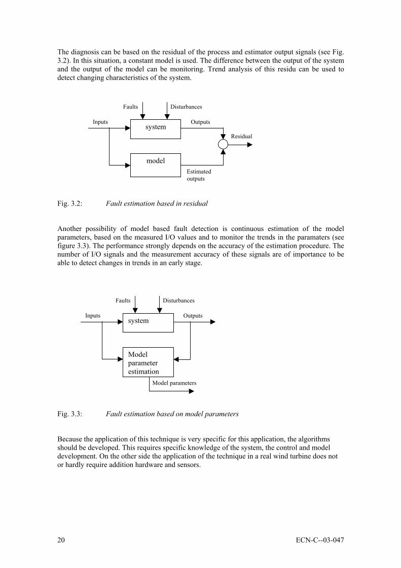
The diagnosis can be based on the residual of the process and estimator output signals (see Fig.3.2). In this situation, a constant model is used. The difference between the output of the systemand the output of the model can be monitoring. Trend analysis of this residu can be used todetect changing characteristics of the system.
Fig. 3.2: Fault estimation based in residual
Another possibility of model based fault detection is continuous estimation of the modelparameters, based on the measured I/O values and to monitor the trends in the paramaters (seefigure 3.3). The performance strongly depends on the accuracy of the estimation procedure. Thenumber of I/O signals and the measurement accuracy of these signals are of importance to beable to detect changes in trends in an early stage.
Fig. 3.3: Fault estimation based on model parameters
Because the application of this technique is very specific for this application, the algorithmsshould be developed. This requires specific knowledge of the system, the control and modeldevelopment. On the other side the application of the technique in a real wind turbine does notor hardly require addition hardware and sensors.
system
model
DisturbancesFaults
OutputsInputs
Estimatedoutputs
Residual
system
Modelparameterestimation
DisturbancesFaults
Model parameters
OutputsInputs
ECN-C--03-047 21
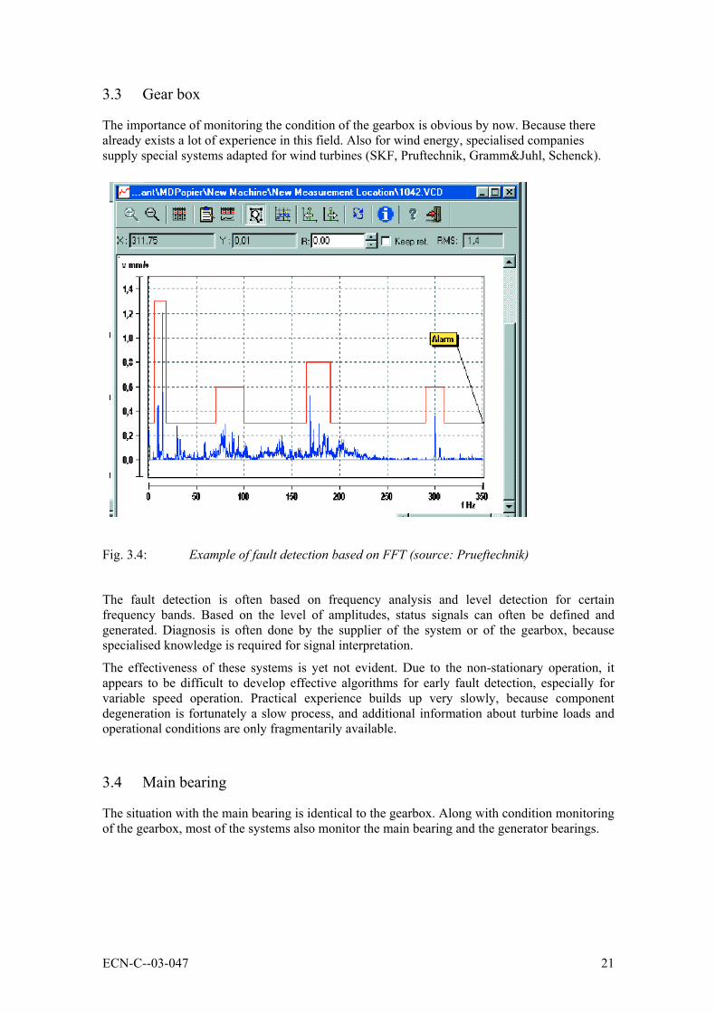
3.3 Gear box
The importance of monitoring the condition of the gearbox is obvious by now. Because therealready exists a lot of experience in this field. Also for wind energy, specialised companiessupply special systems adapted for wind turbines (SKF, Pruftechnik, Gramm&Juhl, Schenck).
Fig. 3.4: Example of fault detection based on FFT (source: Prueftechnik)
The fault detection is often based on frequency analysis and level detection for certainfrequency bands. Based on the level of amplitudes, status signals can often be defined andgenerated. Diagnosis is often done by the supplier of the system or of the gearbox, becausespecialised knowledge is required for signal interpretation.
The effectiveness of these systems is yet not evident. Due to the non-stationary operation, itappears to be difficult to develop effective algorithms for early fault detection, especially forvariable speed operation. Practical experience builds up very slowly, because componentdegeneration is fortunately a slow process, and additional information about turbine loads andoperational conditions are only fragmentarily available.
3.4 Main bearing
The situation with the main bearing is identical to the gearbox. Along with condition monitoringof the gearbox, most of the systems also monitor the main bearing and the generator bearings.

22 ECN-C--03-047
3.5 Sound registration
During the project, it was decided to cancel the condition monitoring based of sound/noise.From the manufacturer point of view it appeared difficult to define a development target for thisitem. In practical situation, maintenance personnel can often well observe what is wrong. This isbased on long experience, and it will be very difficult to extract this information from noisesignals. Furthermore, the sound is heavily disturbed by the background and also stronglydependent on the operational conditions of the turbine.
3.6 Blade monitoring
There are already some practical examples of blade monitoring. LM for instance has a systemavailable, which operates completely, stand-alone and which is focussed on detectiing excessivevibration levels and sending messages to the company. The system uses acceleration sensors.The system has mainly been used for prototyping but was intended to be widely applied for stallregulated turbines in the 600 kW range.
NGUp has a sensor available, which was developed by blade manufacturer Aerpac. This sensoris based on a proportional proximity sensor, in combination with a bar mechanism. This systemwas developed for the same purpose as the LM sensor.
Fig. 3.5: Principle of fibre optic blade monitoring
Although the LM system as well as the Aerpac sensor already have a track record, applicationof fibre optic measurement techniques are foreseen as the most promising.
4 FBGs located at each ofthe four quadrants at the 2/3 span position and at the root of each blade
Armoured fibre optic cable, spliced to each array, and attached to the inner surface of blade using glass fibre tape and epoxy resin
Optic Fibre termination box. Glassed to surface of blade. Supplied with bulk head connector for connection to the OFSSS II unit
OFSSS II unit mounted vertically on rotor bulk head
CAN-bus serial connection via slip ringsData Management PC
Connector at end of lead allowing fibres in other blades to be connected

ECN-C--03-047 23
4. INSTRUMENTATION OF THE LAGERWEY 50/750
Initially, the prototype of the Lagerwey 50/750 (see Fig. 4.1)was chosen for the execution of themeasurement programme. Important advantage of this turbine at that time was the fact that thisturbine was already instrumented to carry out load measurements.. At the beginning of theproject, the turbine was a prototype and it was expected that after one year of operation, theconfiguration should remain stable, and that the turbine should stay in operation as a productionturbine. Initially, the fact that the turbine was a prototype, only seemed to have advantages.There was a close collaboration with the manufacturer, which makes the instrumentation easier,the design data was accessible, and the turbine could be adjusted very easily without too manyconsequences for the revenue losses.
Fig. 4.1: Lagerwey LW 50/750 turbine
An important disadvantage of the choice of this turbine design with respect to a generalcondition monitoring project was the specific design. For condition monitoring the gearbox isprobably the most vulnerable component, while the Lagerwey turbine is a direct drive machine.Also the main bearing is specific for this design. So for this turbine the condition monitoringaspect were mainly focussed on the pitch mechanism, the main bearing and general detectionmechanisms. The disadvantages were recognised in the beginning of the project but theyseemed minor as compared to the advantages mentioned above.
The main bearing is a critical component for this design. This bearing is not a normal rollerbearing, but a 4 point ring bearing with a large diameter. Rothe Erde, the supplier of the bearinghas also delivered a vibration sensor which was also incorporated in the measurement system.Besides the vibration, also the bearing temperature was monitored.

24 ECN-C--03-047
For the execution of the measurement program, a measurement and instrumentation plan [5] hasbeen prepared. This plan includes long term stationary measurement without faulty conditionsin order to define the reference values for all normal conditions (wind speed, wind direction,start-up and stop procedures, etc.). Besides the stationary measurements, the plan also includedmeasurements under faulty conditions (e.g. oblique inflow, pitch errors, etc.). It was expectedthat within one year measurements, significant degradation of main components would notoccur. Therefore, the measurement campaign intended to focus on the assessment of the variouscondition monitoring techniques and the data collection and analysis. A summary of theinstrumentation plan is given in Annex A.
The condition monitoring systems were installed in the turbine and the entire measurementsystem was functioning by the end of 2000. The measurement program should start as soon asthe configuration was stable. This situation was expected in the beginning of 2001 but at thattime, Lagerwey announced that the blades would be changed very soon, probably in May 2001.In January 2002, Lagerwey was still carrying out major changes to the turbine (blades andfrequency converter) and Lagerwey could not guarantee that the configuration would remainunchanged for a period of 3 months.
Although some data was collected in 2001, it was insufficient to draw robust conclusions. In thebeginning of 2002, it was decided to stop the measurement campaign and to continue the projectwith another partner and another turbine. The fact that the turbine was a prototype seemedadvantages in the beginning of the project but in the end it turned out that this was the maincause for not successfully finalising the project.
At that time it was realised that within the constraints of the project (mainly limited time andbudget) the initial project objectives could not be fully met. First of all, another project partnerand another turbine had to be found. Secondly, the new turbine had to be instrumented again,and finally a measurement period of at least 3 to 6 months was necessary. Within the constraintsof the project, only the instrumentation of a new turbine was feasible. Finalising themeasurements and collecting relevant data was not possible. The new partner with which theproject could be continued was Siemens Nederland N.V.. Siemens has shown their interest inthe project for some time, and offered the possibility to use the Enron 1.5S turbine inZoetermeer for condition monitoring measurements. (see Chapter 5).

ECN-C--03-047 25
5. INSTRUMENTATION OF THE ENRON 1,5 S
A second possibility for execution of measurements was the ENRON 1.5S-turbine of Siemensin Zoetermeer, see Fig. 5.1. This turbine has representative features for large wind turbines foroffshore applications:1. Conventional drive train with gearbox and main bearing2. Individual electrical pitch mechanism3. Double fed asynchronuous generator4. Variable speed operation5. Operation focussed on production
Fig. 5.1: Enron 1.5s turbine of Siemens in Zoetermeer
However, with respect to the experiments that had to be carried out in the WT_Ω project, thechoice of the turbine had some disadvantages:1. Design information of the turbine was not available for the project team2. the turbine manufacturer was indirectly involved which slowed down the instrumentation
process.3. Load measurements were not available, so the load measurements had to be applied again.
From the beginning on, Siemens had the intention to support the project. However, the effortsbefore the actual instrumentation started took more time than originally planned, mainly due tocontractual matters, insurance and arrangements with respect to liability.

26 ECN-C--03-047
It was evident to involve this specialised company in the project. SKF was interested inparticipating in the project with a condition monitoring system (WindCon), especially designedfor wind turbines. The latter partner was invited because of the presence of a gearbox and theconventional main bearing.
At the end of 2002, all instrumentation was available and tested at ECN and brought over toZoetermeer. The instrumentation of the rotor sensors has been carried out, the interface with thewind turbine control system has been installed, as well as the connection between the trafostation and the tower base. The schematics of the instrumentation plan are given in Fig. 5.2.
At the time the data acquisition system was about to be installed, the successor of the WT_Ωproject CONMOW (Condition Monitoring for Offshore Wind Turbines) was approved by boththe EU and Novem. It was decided to postpone the installation of the measurement system sincenew parties were involved and the measurement system had to meet other specifications. Theschematics of the CONMOW measurement system are given in Fig. 5.3. The major differencebetween the two measurement systems is that the CONMOW version is more open for allparties to exchange data through the Internet. This has a strong preference for experiments onthe longer term.

ECN-C--03-047 27
Fig. 5.2: Outline of the measurement system for the WT_Ω project
Nacelle
Tower
RemoteAccess
ECNdata
acquisition
Towerbase
SKF
NacelleECN
Sensors Hub/bladesECN
Trafo station
Opto/
Ethernet
Opto/
Ethernet
HUBPC
ECNIntermediate
storageShiva
IDSNmodem
Internet
ECNremoteAccess
ECNData base
Removabledisk
Opto/
signal
SensorsMeteo
ECNinterfacing

28 ECN-C--03-047
Fig. 5.3: Outline of the measurement system for the CONMOW project
Tower
Remote Access
Tower base
Nacelle
Specialisedcompany 2
SpecialisedCompany
1
ECNdata
acquisition
Switch
Ethernet/
Opto
Opto/
Ethernet
SwitchPC
ECNIntermediate
storageRouter
IP
ADSLmodem
Internet
ECN
PublicHTML-pages
SFTP (data)SMTP (email)
HTTP (HTML-pages)TCP/IP protocol
SpecialisedCompany
2
SpacialisedCompany 1
Visitors
NacelleECN
Trafo stat.ECN
SensorsSensors Hub/bladesECN
ECNBack upfacility
ECNfire wall

ECN-C--03-047 29
6. CONCLUSIONS
ECN has carried out the project WT_Ω (WT_OMEGA = Wind Turbine Operation andMaintenance based on Condition Monitoring) from 2000 to 2003 with financial support fromNOVEM. The objectives of the project were threefold:1. making an inventory of the available condition monitoring techniques and selecting a set
which has added value for wind turbines;2. to instrument a wind turbine and demonstrate some of the selected condition monitoring
techniques;3. identifying areas for further development, e.g. new sensors, algorithms for data analysis ,or
integration of the systems in the turbine and wind farm controller.
The first objective has resulted in a literature study, published in [1]. The second objectiveresulted in two instrumented turbines, the LW 15/750 and the Enron 1.5s turbine of Siemens inZoetermeer. Unfortunately, both turbines did not run under stable conditions for a longer periodof time during the project, so a relevant set of measured data to draw conclusions from ismissing. The final third objective could thus not be met.
The positive result however is that the project ended with an instrumented turbine with which itis possible to continue the condition monitoring experiments over a longer period of time. Thisis necessary because trends in characteristic signals will manifest very slowly and that it mighttake years in stead of months to detect significant changes. So, the CONMOW project(Condition Monitoring of Offshore Wind Turbines), which is the successor of WT_ Ω, has betterprospects to meet the original WT_ Ω objectives, The WT_ Ω plan was clearly too ambitious.
From the experiences gained up to now, the following conclusions were drawn.
• There is a growing interest in the application of condition monitoring techniques for windturbines. The reasons for this increasing interest are:1. The increasing installed power per wind turbine and the related higher investments2. High costs for corrective maintenance at a too early stage, and need for reducing them3. Future off-shore applications with limited access for corrective maintenance4. Requirements from insurance companies in Germany to regularly replace and repair
drive train parts.5. Growing interest of specialised companies which supply condition monitoring systems
• Some issues may hamper the introduction of condition monitoring in wind energy.However, there are still some important points which limits the success on a longer term:1. Effectiveness of condition monitoring systems is difficult to demonstrate due to the long
measurement periods that are required.2. Further development of algorithms for early failure prediction requires long time
periods and additional measurement data.3. Interpretation of results still requires specialised knowledge.
• The number of available systems based on vibration analysis, developed for other branchesof industry and adapted for wind turbines, is increasing and available for reasonable prices.
• The ability of failure forecasting of the available system is not yet evident. Algorithmsshould be adapted and verified for non-stationary application in wind turbines.
• Specialised involvement will be of growing importance with respect to conditionmonitoring for the bearings, gearboxes and generator bearings. Condition monitoringfunctions are embedded in special hardware, integrated in the system top be monitored and

30 ECN-C--03-047
separated from the wind turbine control system. The supplier of the monitored system willoften also perform interpretation of signals.
• General condition monitoring techniques, which can be interpreted as extension andrefinement of current safeguarding techniques should be developed for this applicationbased on known algorithms and methods, like model reference methods.
• General condition monitoring techniques can be integrated in the wind turbine controlsystem, which means that only development costs are involved, however often customisedfor each wind turbine type.
• Development and verification of condition monitoring techniques requires long termmeasurements in a production environment. Normally such a facility is not available. Thewind turbine in Zoetermeer gives the opportunity to create an environment facilitating thisdevelopment. The instrumentation scheme, as implemented for WT-Ohm has been modifiedfor the CONMOW project It has been extended and based on Internet technology in order tobe able to incorporate the equipment (and knwoledge) of more specialised companies, andto realise automated interchange and transport of data.

ECN-C--03-047 31
7. REFERENCES
1 Verhoef, J.P.; Verbruggen, T.W.: Conditiebewaking aan windturbines; Een verkennendestudie. ECN-C--058, juni 2001
2 Verhoef, J.P., Verbruggen, T.W.: Eindrapportage Glasvezelsensoren bladen. ECN-WindMemo-01-012, juni 2001
3 Stam, F.R. Monitoring & condition-monitoring aan windturbines. 76104-GR-01, januari1998
4 Abbekerk, M. Condition monitoring aan windturbines. ECN-Z&W Memo-99-027, mei1999
5 Verhoef, J.P.; Verbruggen, T.W.: Meetplan Conditionmonitoring aan de LagerweyLW50/750 Nieuwe Tonge, Nederland. ECN-Wind Memo-00-025, November 2000
6 CONMOW (Condition Monitoring Offshore Wind Turbines). Proposal BSE, November2002
7 Rademakers, L et al. “Risk Based Maintenance Management to Reduce the OperationalCosts of Wind Energy”, DEWEK 2000, p 49
8 H. Braam, et al: “Lightning Damages of OWECS - Part 3:Case Studies”; ECN-C--02-054, May 20021
9 H. Braam; L. Rademakers, M. Zaaijer, G. van Bussel: “Assessment and optimisation ofoperation and maintenance of offshore wind turbines”; paper to be presented at EWEC2003

32 ECN-C--03-047

ECN-C--03-047 33
APPENDIX A: MEASUREMENT AND INSTRUMENTATION PLANOF THE LAGERWEY 50/750
The measurement plan of the Lagerwey 50/750 was focussed on the following main items:
1. Measuring the performace of the pitch system
2. General measurements of the wind turbine
3. Measurements on the main bearing
ad 1: Measuring the performance of the pitch system.
The blade angles are normally adjusted by individual servo motors. Each blade has anindependent control loop, based on position control. The systems have a common position setpoint signal. Power is supplied via a slip ring set. The servo motors are directly coupled with areduction box.
For emergency situations, the blades are moved to the vane position by DC-motors directlyconnected with accumulators. The DC-motors are coupled with the same reduction box as theservo-motors via an electromechanical coupling.
In order to monitor the performance of the pitch system, the following signals are measured:
1 Pitch angle (3)
2 Current to servomotor (3)
3 Pitch angle velocity (3)
4 Pitch angle set point (1)
5 Servo speed set point (3)
6 Temperature reduction box (3)
7 Temperature servo motor (3)
8 Status signal servo brake
9 Status emergency
10 Accumulator current
ad 2: General measurements of the turbine
The general measurements are used to support signal analysis for the pitch system as well as forthe main bearing, together with results from load measurements. On the other side, thismeasurments can be used stand alone in order to monitor the wind turbine performance ingeneral terms. The signals to be measured are:
1 Rotor speed
2 Azimuth angle
3 Electrical power
4 Wind speed met mast
5 Wind speed wind turbine
6 Wind direction met mast
7 Yaw misalignment
34 ECN-C--03-047
8 Air temperature
9 Air pressure
10 Rain detection
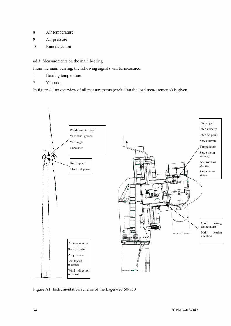
ad 3: Measurements on the main bearing
From the main bearing, the following signals will be measured:
1 Bearing temperature
2 Vibration
In figure A1 an overview of all measurements (excluding the load measurements) is given.
Figure A1: Instrumentation scheme of the Lagerwey 50/750
WindSpeed turbine
Yaw misalignment
Yaw angle
Unbalance
Air temperature
Rain detection
Air pressure
Windspeedmetmast
Wind directionmetmast
Pitchangle
Pitch velocity
Pitch set point
Servo current
Temperature
Servo motorvelocity
Accumulatorcurrent
Servo brakestatus
Main bearingtemperature
Main bearingvibration
Rotor speed
Electrical power

ECN-C--03-047 35
All measurements will be executed continuously in 10-minute periods. Data storage will bedone following a capture matrix based on statistical values (mean and standard deviation of thewind speed).
Additional to the continous measurments during normal turbine operation, special measurmentcampaigns are foreseen. These campaigns are focussed on simulated faults in the pitchsystem.

36 ECN-C--03-047

ECN-C--03-047 37
APPENDIX B: MEASUREMENT AND INSTRUMENTATION PLANOF THE ENRON 1,5S TURBINE
The measurement programme for the Siemens Enron turbine is focussed on the following items:
1. Measurement of pitch system variables
2. Measurements of main bearing parameters
3. Measurement of gearbox and generator parameters
4. General wind turbine parameters.
ad 1: Measurement of pitch system variables
The ENRON turbine also has independent pitch control for all three blades. It is equipped withDC-servo-motors, which are used for normal as well as for emergency pitch adjustment.Because the ENRON-turbine is a production turbine, the control signals are not all measurable.The following signals are available after additional provisions from GE-side:
1 Pitch angle (3)
2 Desired pitch angle (1)
3 Temperature reduction box / servo motor (3)
4 Motor current (3)
ad 2: Measurements of main bearing parameters
The measurement signals of the main bearing are used by SKF and used for their own system.The following signals are used:
1 Acceleration main bearing (transversal)
2 Acceleration main bearing (radial)
3 Main bearing temperature
ad 3: Measurement of gearbox and generator parameters
The measurement signals for the gearbox and generator are also used by SKF for their ownsystem. These signals are:
1 Acceleration gearbox (transversal)
2 Acceleration gearbox (radial)
3 Acceleration generator (radial)

38 ECN-C--03-047
ad 4: General wind turbine parameters
The general wind turbine parameters are used for signals analysis of condition monitoringtechniques on subsystem level (pitch system, main bearing, gearbox and generator) as well asfor safeguarding on a general level. Additional to the common process parameters, also the mainshaft torque as well as the load on the blades will be measured:
1 Wind speed
2 Rotor speed
3 Azimuth angle
4 Electrical power
5 Unbalance
6 Yaw angle
7 Yaw misalignment
8 Main shaft torque
9 Lead lag moment blade root
10 Flap moment blade root
11 Air temperature
12 Air pressure
13 Rain detection
All measurements will be executed continuously in 10 minute periods and stored on aremovable hard disk in the tower base PC. It was decided not to use a capture matrix because ofseveral reasons. For this turbine no measurement mast was available. For the wind speedmeasurements the anemometer on the nacelle was used so that the measurements are disruptedby blade passage. For a capture matrix, the wind speed and variance are normally used forclassification. On the other hand, the storage capacity on a removable hard disk was largeenough to store data for about a month, so from this point of view there was not really a needfor using a capture matrix.
Additional to the continuous measurements, short campaigns with simulated faults were alsoforeseen. For the pitch system faults can be introduced without the risk for permanent turbinedamage. For the main bearing, gearbox and generator it is much more difficult to simulate faultysituations without risk for permanent damage.
ECN-C--03-047 39
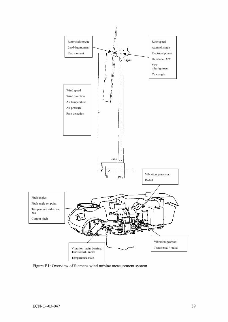
Figure B1: Overview of Siemens wind turbine measurement system
Pitch angles
Pitch angle set point
Temperature reductionbox
Current pitch
Vibration main bearing:Transversal / radial
Temperature main
Vibration gearbox:
Transversal / radial
Vibration generator:
Radial
Rotorspeed
Azimuth angle
Electrical power
Unbalance X/Y
Yawmisalignment
Yaw angle
Wind speed
Wind direction
Air temperature
Air pressure
Rain detection
Rotorshaft torque
Lead-lag moment
Flap moment