xserve setup guide - apple · pdf fileother company and product names mentioned herein ... nor...
TRANSCRIPT

XserveSetup Guide
Includes setup, expansion, and hardware specifications for the Xserve
K
Apple Computer, Inc.
© 2006 Apple Computer, Inc. All rights reserved.
Under the copyright laws, this manual may not be copied, in whole or in part, without the written consent of Apple. Your rights to the software are governed by the accompanying software license agreement.
The Apple logo is a trademark of Apple Computer, Inc., registered in the U.S. and other countries. Use of the “keyboard” Apple logo (Option-Shift-K) for commercial purposes without the prior written consent of Apple may constitute trademark infringement and unfair competition in violation of federal and state laws.
Every effort has been made to ensure that the information in this manual is accurate. Apple is not responsible for printing or clerical errors.
Apple1 Infinite LoopCupertino, CA 95014-2084408-996-1010www.apple.com
Apple, the Apple logo, FireWire, Mac, Macintosh, Mac OS, and Xserve are trademarks of Apple Computer, Inc., registered in the U.S. and other countries.
The FireWire logo and SuperDrive are trademarks of Apple Computer, Inc.
Apple Store is a service mark of Apple Computer, Inc., registered in the U.S. and other countries.
Intel and Intel Core are trademarks of Intel Corp. in the U.S. and other countries.
This product includes software developed by the University of California, Berkeley, and its contributors.
Other company and product names mentioned herein may be trademarks of their respective companies. Mention of third-party products is for informational purposes only and constitutes neither an endorsement nor a recommendation. Apple assumes no responsibility with regard to the performance or use of these products.
Simultaneously published in the United States and Canada.
034-3914-A/10-28-06

3
Contents
5 About This Guide
7 Chapter 1: Installing the Xserve8
Tools and Parts You’ll Need
9
Choosing a Suitable Location
11
Installing the Xserve
20
Where to Go from Here
21 Chapter 2: Installing or Replacing Components22
Xserve at a Glance—Internal Components
24
Installing or Replacing an Apple Drive Module
28
Removing or Installing a Power Supply
30
Opening and Closing the Xserve
33
Adding Memory
38
Installing a PCI Card
44
Replacing the Battery
47 Appendix A: Specifications
51 Appendix B: Safety and Maintenance51
Important Safety Information

4
Contents
52
Handling the Xserve
53
Protecting the Optical Drive
53
Power Supply
54
Cleaning the Xserve
54
Apple and the Environment
54
Health-Related Information About Computer Use
57
Regulatory Compliance Information
5
Pref
ace
About This Guide
This setup guide shows you how to install the Xserve in a rack and how to install or replace components inside the Xserve.
For information about unpacking the Xserve and installing it in a rack, see Chapter 1.
For information about installing or replacing drive modules, memory, PCI cards, power supplies, or the system battery, see Chapter 2.
For a summary of Xserve specifications, see Appendix A.
For safety and regulatory information, see Appendix B.
When You Finish Installing the Xserve
For information about starting up the Xserve for the first time, configuring the server software, and using the Xserve, see the
Xserve User’s Guide
on the Admin Tools disc that comes with the Xserve.
To learn about the Mac OS X Server software installed on the Xserve, see
Mac OS X Server Getting Started
, also on the Admin Tools disc that comes with the Xserve.
The
Xserve Setup Guide
,
Xserve User’s Guide
,
Mac OS X Server Getting Started
, and other server guides are also available at www.apple.com/server/documentation.

6 Preface
About This Guide
For More Information
The Apple Service & Support website offers in-depth product information and technical resources, including articles, discussions, and downloadable software updates. Visit the site at www.apple.com/support/xserve.

7
1
1
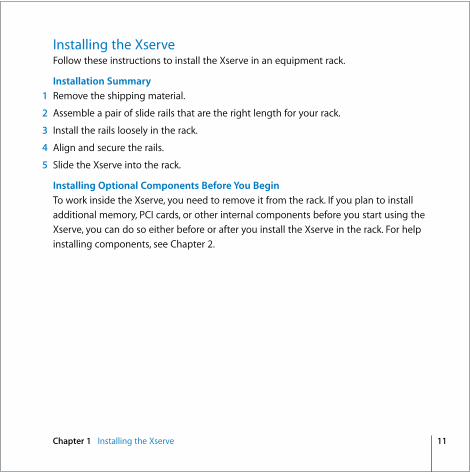
Installing the Xserve
This chapter shows you how to install the Xserve in an equipment rack.
The information in this chapter will help you gather the tools you’ll need, choose a suitable location for the Xserve, and install it in a rack. When you’ve finished installing the Xserve, you’ll be referred to the
Xserve User’s Guide
for information about starting up the Xserve for the first time.

8 Chapter 1
Installing the Xserve
Tools and Parts You’ll NeedÂ
A medium-size (#1) Phillips screwdriver
Â
The slide rails, rail extensions, and alignment tool that come with the Xserve
Short extensions for racks24 to 29 inches deep (2)
Rails for use with racksof all depths (2)
Alignment guide
Long extensions for racks29 to 36 inches deep (2)
Enclosure key

Chapter 1
Installing the Xserve
9
Choosing a Suitable Location
The Xserve is designed for rack mounting. Review the following paragraphs to be sure the location you choose satisfies the Xserve space, electrical, and environmental requirements.
Rack Compatibility
You can install the Xserve in any open or closed (cabinet-style) 19-inch-wide four-post rack from 24 to 36 inches deep using the rails included with the Xserve. The Xserve occupies 1.75 inches (1U) of vertical rack space.
Important:
Your rack should satisfy the American National Standards Institute (ANSI)/Electronic Industries Association (EIA) standard ANSI/EIA-310-D-92, International Electrotechnical Commission (IEC) 297, and Deutsche Industrie Norm (DIN) 41494.
Rack Stability
Make sure the rack is stable and strong enough to support installed equipment. When working with equipment in the rack, never slide out more than one unit at a time, and keep all other equipment secured in the rack.
Space Requirements
Air to cool the Xserve flows from front to back. Make sure nothing blocks any of the openings in the front and back panels and case of the Xserve. When installed, the Xserve slides in and out of the rack from the front. Make sure you have at least 36 inches clear in front of the Xserve so you can remove it.

10 Chapter 1
Installing the Xserve
Electrical Power Requirements
Be sure that the available circuitry and power connections are adequate for the combined power needs of the Xserve and all other equipment in the rack. See Appendix A for information about the electrical power requirements of the Xserve. Make sure that the power connections for the Xserve and all other equipment are grounded according to local and national standards.
Operating Environment
Make sure that the ambient temperature in the rack is within the limits established for the Xserve and all other equipment. See Appendix A for the Xserve operating temperature requirements. Make sure that both the rack itself and the room where the rack is located are sufficiently ventilated to maintain the necessary temperature range.
Do not blockthe air flowingthrough the Xserve.
Chapter 1
Installing the Xserve
11
Installing the Xserve
Follow these instructions to install the Xserve in an equipment rack.
Installation Summary
1
Remove the shipping material.
2
Assemble a pair of slide rails that are the right length for your rack.
3
Install the rails loosely in the rack.
4
Align and secure the rails.
5
Slide the Xserve into the rack.
Installing Optional Components Before You Begin
To work inside the Xserve, you need to remove it from the rack. If you plan to install additional memory, PCI cards, or other internal components before you start using the Xserve, you can do so either before or after you install the Xserve in the rack. For help installing components, see Chapter 2.
12 Chapter 1
Installing the Xserve
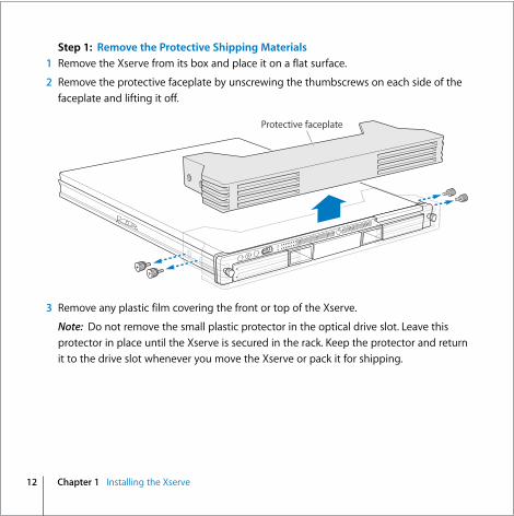
Step 1: Remove the Protective Shipping Materials
1
Remove the Xserve from its box and place it on a flat surface.
2
Remove the protective faceplate by unscrewing the thumbscrews on each side of the faceplate and lifting it off.
3
Remove any plastic film covering the front or top of the Xserve.
Note:
Do not remove the small plastic protector in the optical drive slot. Leave this protector in place until the Xserve is secured in the rack. Keep the protector and return it to the drive slot whenever you move the Xserve or pack it for shipping.
Protective faceplate

Chapter 1
Installing the Xserve
13
Step 2: Assemble the Mounting Rails
The Xserve comes with both short and long extensions that you combine with standard front rails to create a pair of rails that are the right depth for your rack.
1
Slide a matching rear extension onto each of the two front rails.
Long extension
Short extension
These pegs engage theslots in the extension.
Rail
The extension goes onthe outside of the rail.
Engage the pegsin both slots.
This notch shouldbe on the bottom.
This end is up.

14 Chapter 1
Installing the Xserve
Step 3: Mount Rails Loosely in the Rack
1
Place an assembled rail in the rack (it will support itself temporarily while you gather the fasteners). The way you fit the rail depends on the rack.
Â
If you have a square-hole rack, start with the rail flanges inside the posts and expand the rail between the front and rear posts until the small round guide on each flange extends through the rail.
Expand the railsso they fit insidethe rack posts.
Position the spaceron the outside of thepost, and over thethreaded guide on the rail.
Position the spacer so the smallblock on the back engages thesquare hole in the rack support.
Use the screws that camewith the rail to secure thespacer to the rail.

Chapter 1
Installing the Xserve
15
Â
If you have a threaded-hole rack, start with the rail flanges outside the rack posts and compress the rail into position.
2
Slide a spacer, arrow up, over the small round guide at the ends of each rail and install the mounting screws finger tight.
Note:
Don’t tighten the mounting screws until you align the rails in the next step.
Position the spacerover the threaded guideon the rail assembly.
This end is up.
Compress the railsso that they fit on theoutside of the rack posts.
Use either eight 10-32 or eightM5 screws (supplied), depending onwhich type your rack requires.

16 Chapter 1
Installing the Xserve
Step 4: Align and Secure the Rails
To make sure the Xserve slides easily in and out of the rack, use the alignment guide to position the rails in the rack before tightening the mounting screws.
1
Insert the alignment guide in the front of the rails.
2
Tighten the front mounting screws
Important:
If you have a square-hole rack, make sure the raised alignment block on the back of each mounting spacer is seated properly in the hole in the rack post as you tighten the screws.
3
Tighten the rear mounting screws.
4
Remove the alignment guide.
Insert the alignmentguide into the railsand tighten all the screws.

Chapter 1
Installing the Xserve
17
Step 5: Slide the Xserve into the Rails
1
Guide the slides on the Xserve into the channels on the rails.
Important:
Make sure both the left and right slides on the Xserve go inside the rail channels. If you have difficulty, set aside the Xserve and use the alignment guide to check the spacing between the rails.
2
Slide the Xserve into the rack until it stops.
3
Tighten the thumbscrews at each end of the front panel to secure the Xserve in the rack.
4
Remove the plastic optical drive protector.
Note:
Keep the protector and return it to the drive slot whenever you move the Xserve to another location or pack it for shipping.
Thumbscrews
Optical drive protector

18 Chapter 1
Installing the Xserve
Step 6: Connect the Cables
1
Connect a power cord to the power supply and secure it with the wire clip.
Note:
The fan in the power supply and some system status lights come on when you connect the power cord, before you turn on the Xserve.
2
Connect the network cables.
Note:
If you’re using only one Ethernet cable, connect it to port 1.
Serial console port Display port Ethernet port 2 Ethernet port 1
System identifierbutton/light
FireWire 800ports (2)
USB 2.0 ports (2)
Power supplybay 2
Power supplybay 1
System information tag(pullout tab)

Chapter 1
Installing the Xserve
19
Step 7: Connect a Keyboard, Display, and Mouse (Optional)
You can connect a display, keyboard, and mouse directly to the Xserve. You can also manage the Xserve without connecting a display or keyboard by using tools such as Server Admin, Server Monitor, Apple Remote Desktop, and the command line.
1
Connect the keyboard to one of the USB ports on the back panel.
2
Connect the mouse to the second USB port or to the keyboard.
3
Connect the video cable.
To use the built-in video card, connect the video cable to the display port on the back panel using the appropriate adapter.
To use an optional PCI video card, connect the display’s video cable to the card.
Note:
The Xserve comes with a mini-DVI to VGA adapter. A mini-DVI to DVI adapter is sold separately. A mini-DVI to video adapter is not supported. You may need a different adapter to connect a display to an optional PCI video card.
USB 2.0 ports (2)
VGA adapter
Display port

20 Chapter 1
Installing the Xserve
Where to Go from Here
When you finish installing the Xserve, you can find information about starting up, configuring, and using it in these guides:Â
Xserve User’s Guide
(a PDF file on the Xserve Admin Tools disc)
Â
Mac OS X Server Getting Started
(a PDF file on the Xserve Admin Tools disc)
Starting Up the Xserve
The
Xserve User’s Guide
includes:Â
An overview of Xserve controls and components
Â
Information about how to start up and shut down the Xserve
Â
Tips on monitoring the status of the Xserve and the services it hosts
Â
Instructions for updating or reinstalling the server software
Â
Solutions to some common problems
Configuring the Server Software
The first time you turn on the Xserve, the Server Assistant asks you for basic information that Mac OS X Server needs to start up and connect to the network. For step-by-step instructions that guide you through the setup process, see
Mac OS X Server Getting Started
on the Admin Tools disc that comes with the Xserve. For information about additional settings for your Intel-based Xserve, see the
Xserve User’s Guide
.

21
2
2
Installing or Replacing Components
This chapter shows how to install or replace drive modules and internal Xserve components.
You can add or replace these components while the Xserve is in the rack:Â
Drive module (page 24)
Â
Power supply (page 28)
To install these components, you must remove the Xserve from the rack and open it:Â
Memory (page 33)
Â
PCI card (page 38)
Â
Battery (page 44)
For a quick glance inside the Xserve, turn the page.

22 Chapter 2
Installing or Replacing Components
Xserve at a Glance—Internal Components
DIMM slots (8)
Fan array
Expansion slot 1Power supplybay 2
Power supplybay 1
Expansion slot 2
Battery
Rack release latch Drive bay 1 Drive bay 2 Drive bay 3

Chapter 2
Installing or Replacing Components
23
Power supply bays
You can install one or two power supplies in the Xserve. When two supplies are installed, they share the load. If one supply fails, the other takes over the full load. For information, see “Removing or Installing a Power Supply” on page 28.
BatteryThe battery on the main logic board powers the system clock and preserves basic system settings (in NVRAM) when power supplies are disconnected. For information, see “Replacing the Battery” on page 44.
PCI-X and PCI-E card slot (slot 1)You can install a full-length (9 inch) PCI-X or PCI-E card in this slot using the appropriate riser. For information, see “Installing a PCI Card” on page 38.
PCI-E slot (slot 2)You can install a half-length (6.6 inch) PCI-E expansion card in this slot using a PCI-E riser. For information, see “Installing a PCI Card” on page 38.
DIMM slotsYou can expand memory in the Xserve up to 32 gigabytes (GB) by installing pairs of fully buffered, error-correcting dual inline memory modules (FB-DIMMs) in these slots. For information, see “Adding Memory” on page 33.
Fan arrayThe fan array draws cooling air through the Xserve from front to back.
Rack release latchThis latch stops the Xserve about halfway out of the rack. Press to release.
Drive baysYou can install SAS (Serial Attached SCSI) and SATA (Serial ATA) drives. For information, see “Installing or Replacing an Apple Drive Module” on page 24.

24 Chapter 2 Installing or Replacing Components
Installing or Replacing an Apple Drive ModuleThe drive modules in the Xserve are hot-pluggable, so you can add, remove, or replace them while the Xserve is operating. A status light on the drive handle indicates when it’s safe to remove a drive without risk to the information stored on it.
About Drive Modules for the XserveThe Xserve accepts both SAS (Serial Attached SCSI) and SATA (Serial ATA) drive modules.
To install or replace a drive module:1 If the Xserve case is locked, use the enclosure key to unlock the security lock on the
front panel.

Chapter 2 Installing or Replacing Components 25
2 Remove the blank drive module or the drive module that’s currently installed.
If there is a blank drive module in the bay, press the handle on the front to pop it out. Then pull the module out and put it in a safe place.
Important: Save the blank drive module. Always keep a blank drive module in any unused drive bay to maintain proper airflow through the Xserve.
Press the blank drivemodule to pop out the handle.

26 Chapter 2 Installing or Replacing Components
If there is a drive module already in the bay:
a Make sure the drive currently in the bay is not being used by any application or being shared by the Xserve. (See the Mac OS X Server documentation for information about shared volumes.)
b Unmount all volumes hosted by the drive using the Mac OS X Server command-line tools or by dragging the volume icons to the Trash.
c Press the handle on the drive module so the handle pops out.
d Wait for the green, upper disk status light to go off. Then grasp the handle, pull the drive module out of the bay, and set it aside.
Remove the blankdrive module from the bay.

Chapter 2 Installing or Replacing Components 27
3 Pick up the drive module you are installing, press and release its handle to open it, and slide the module into the bay until it is firmly seated.
4 Press the handle in flush with the front panel.
The disk status light turns green to indicate normal operation.

28 Chapter 2 Installing or Replacing Components
Removing or Installing a Power SupplyYou can replace or install a power supply from the back panel without removing the Xserve from the rack. If the Xserve has two power supplies, they are hot-swappable; the Xserve continues to operate using only one supply while the second is removed.
To remove a power supply:1 Unplug the power cord from the power supply you are removing.
2 Pull the handle to release the power supply and slide it out of the bay.
WARNING: The power supplies in a running Xserve might be hot.
Pull the handle to unlatch thepower supply and remove it.

Chapter 2 Installing or Replacing Components 29
To install a power supply:3 Pull to open the handle on the new power supply, slide it all the way into the bay, and
then press the handle to seat the power supply and lock it in place.
4 Connect the power cord to the power supply.
If the Xserve is already running on a second power supply, the status light on the new supply turns green to indicate normal operation as it starts sharing the load. If the Xserve is not turned on, the supply status light blinks green when the power cord is plugged in to an outlet with power.
Slide the power supply in andpress the handle to seat it.

30 Chapter 2 Installing or Replacing Components
Opening and Closing the XserveBefore you can install or replace memory, PCI cards, or the system battery, you need to shut down the Xserve, remove it from the rack, and open it.
Working Safely Inside the XserveAlways touch the Xserve chassis to discharge static electricity before you handle any components inside the Xserve. To avoid generating static electricity, do not walk around the room until you have finished installing the expansion card, memory, or other internal component and have replaced the Xserve cover. To minimize the possibility of damage due to static discharge, wear an antistatic wrist strap while you work inside the Xserve.
To open the Xserve:1 Shut down the Xserve (see the Xserve User’s Guide for help) and then wait a few
moments to let the Xserve internal components cool.
2 If the Xserve case is locked, use the enclosure key to unlock the security lock on the front panel.
3 Unplug all cables from the Xserve.
Note: If you have trouble releasing a cable from the back panel, try using a small screwdriver or other flat tool to depress the tab on the cable connector.
WARNING: Always shut down the Xserve before opening it to avoid damaging its internal components or the components you want to install. Don’t open the Xserve or try to install items inside while it is turned on. Even after you shut down the Xserve, its internal components can be very hot. Let it cool down before you open it.

Chapter 2 Installing or Replacing Components 31
4 Loosen the thumbscrews at both ends of the front panel.
5 Grasp the thumbscrews and pull the Xserve forward until the safety latches engage (about halfway out of the rack).
6 When the safety latches engage, grip the Xserve where it emerges from the rack, press down on the latch tabs with your thumbs, and slide the Xserve the rest of the way out of the rack rails. Set the Xserve on a flat surface.
Latches
Thumbscrews

32 Chapter 2 Installing or Replacing Components
7 Loosen the thumbscrews at the back of the top cover and slide the cover back and up to remove it.
If you have difficulty removing the cover, check the enclosure lock on the front panel.
Important: To minimize the possibility of damage to Xserve components due to static discharge, wear an antistatic wrist strap while you work inside the Xserve.
8 When you’re finished working inside the Xserve, replace and secure the cover, slide the Xserve back into the rack, and tighten the front thumbscrews to secure the Xserve in the rack. If the server case was locked, use the enclosure key to lock the security lock on the front panel.
Unscrew the twocaptive thumbscrews.
Slide the cover back and lift it off.

Chapter 2 Installing or Replacing Components 33
Adding MemoryThe Xserve has 8 memory slots. The systems come with at least 1 gigabyte (GB) of memory on two fully buffered dual inline memory modules (FB-DIMMs). To improve performance and capacity, you can install additional DIMMs for a total of up to 32 GB of memory.
The 8 memory slots are labelled DIMM 1 through DIMM 8.
1 2 3 4
5 6 7 8
34 Chapter 2 Installing or Replacing Components
About Memory for the XserveYou can use the following memory in the Xserve 667 MHz DDR2 ECC FB-DIMMs
 512 MB, 1 GB, 2 GB, or 4 GB in matching pairs (optimally, 4 or 8 identical DIMMs)
 36 devices per DIMM, maximum
 Error-correcting code (ECC)
Important: Apple recommends that you use Apple-approved FB-DIMMS. Other FB-DIMMs might degrade the performance of the Xserve. DIMMs from older Xserve systems are not compatible with this Xserve.
Note: Before you purchase DIMMs other than those recommended by Apple, make sure that the memory manufacturer conforms to the Joint Electron Device Engineering Council (JEDEC) specification. Make sure that the DIMMs support the correct timing modes and that the Serial Presence Detect (SPD) feature has been implemented in accordance with the JEDEC specification. To check DIMM compatibility, see the Macintosh Products Guide on Apple’s website at www.apple.com/guide. You can purchase Apple-approved memory online from the Apple Store at www.apple.com/store.

Chapter 2 Installing or Replacing Components 35
Installation RulesYou must install DIMMs in pairs, and the DIMMs in each pair must be identical. The first pair is installed in slots 1 and 2. Install the next pair in slots 3 and 4. Subsequent pairs go in slots 5 and 6, and then slots 7 and 8.
For Best PerformanceFor the best possible performance, install eight identical DIMMs in slots 1–8. If you don’t have eight matching DIMMs, install four identical DIMMs in slots 1–4 and a second set of four identical DIMMs in slots 5–8.
Always fill slots 1–4 before you install DIMMs in slots 5–8. After you fill slots 1–4, add a full set of four DIMMs in slots 5–8 instead of just a pair in slots 5 and 6.
The server comeswith at least 2 DIMMs
Add the next pairin these two slots
(Back)
1 2 3 4 5 6 7 8
(Front)
Add the next pairin these two slots
Add the next pairin these two slots

36 Chapter 2 Installing or Replacing Components
To install memory:1 Review the memory installation rules and make sure you have the right type of DIMMs.
2 Shut down the Xserve and unplug all cables.
Important: Be sure the Xserve is turned off and the power cords are unplugged before you install or remove memory.
3 Remove the Xserve from the rack and open it. For instructions, see “Opening and Closing the Xserve” on page 30.
4 Open the ejectors on a slot by pushing them outward.
Important: Don’t touch the gold connectors on the DIMMs.
5 Without touching its gold connectors, align a DIMM in the slot and push straight down on both ends until the DIMM is seated and the ejectors snap upright.
6 Repeat for the second DIMM of the pair and for additional pairs.
Important: Be sure to add DIMMs in the order shown in the illustration.
WARNING: Always wait 5 to 10 minutes for the Xserve to cool down before you try to install memory. DIMMs that are already installed and other components near the DIMM slots may be very hot.

Chapter 2 Installing or Replacing Components 37
ConnectorsNotchEjectors

38 Chapter 2 Installing or Replacing Components
Installing a PCI CardThe Xserve has two PCI slots:Â Slot 1, which accepts full-length (9 inch) PCI-E or PCI-X cards
 Slot 2, which accepts half-length (6.6 inch) PCI-E cards
To install a card, you first insert it into a matching riser, and then install the riser into the slot. The type of card you can install depends on the riser you use:Â A PCI-E riser can go in either slot, and accepts only PCI-E cards
 A PCI-X riser can only go in slot 1, and accepts only PCI-X cards
Connector on PCI-X riser Connector on PCI-E riser

Chapter 2 Installing or Replacing Components 39
About PCI Cards for the XserveThe Xserve accepts PCI cards that meet these specifications:
Slot 1Â 64-bit PCI-X 133 MHz cards (using a PCI-X riser)
 32-bit or 64-bit 33, 66, or 100 MHz PCI or PCI-X cards with 3.3 volt universal signaling
 x8 PCI-E (Express) cards using a PCI-E riser
 9 inch maximum length
 25 Watt maximum power consumption
Slot 2Â x8 PCI-E cards
 6.6 inch maximum length
 25 Watt maximum power consumption

40 Chapter 2 Installing or Replacing Components
To install a PCI card:1 Shut down the Xserve and unplug all cables.
Important: Be sure the Xserve is turned off and the power cords are unplugged before you install or remove a PCI card or riser.
2 Remove the Xserve from the rack and open it. For instructions, see “Opening and Closing the Xserve” on page 30.
WARNING: Always wait 5 to 10 minutes for the Xserve to cool down before you work around the PCI slots. Components near the slots may be very hot.
Expansion slot 1(PCI-E or PCI-X)
Expansion slot 2(PCI-E)

Chapter 2 Installing or Replacing Components 41
3 Loosen the two captive screws that secure the riser bracket to the back panel and gently pull the bracket and riser straight up and out of the slot.
Captive screws

42 Chapter 2 Installing or Replacing Components
4 Remove the screw on the riser bracket, and then remove the port access cover.
5 Seat the PCI card in the riser slot and replace the screw to secure the card in the riser.
Screw
PCI card
PCI riser

Chapter 2 Installing or Replacing Components 43
6 Align the riser with the slot on the main logic board and press to seat it.
7 Tighten the captive screws that secure the riser bracket to the back panel.
8 Return the Xserve to the rack and start it up.
9 Configure the card.
To configure an Ethernet card, open the Network pane of System Preferences.
To configure a Fibre Channel card, open Fibre Channel Utility.
To configure a SCSI card, open Disk Utility.

44 Chapter 2 Installing or Replacing Components
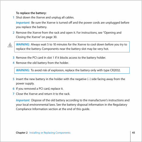
Replacing the BatteryThe Xserve uses a CR2032 lithium coin cell battery to preserve settings such as the date and time when the system is not connected to power. If the date and time change unexpectedly or other system settings are lost, you might need to replace the battery.
For best results, purchase a replacement battery from an Apple-authorized service provider.
The negative (–) side faces away from the power supply.
Chapter 2 Installing or Replacing Components 45
To replace the battery:1 Shut down the Xserve and unplug all cables.
Important: Be sure the Xserve is turned off and the power cords are unplugged before you replace the battery.
2 Remove the Xserve from the rack and open it. For instructions, see “Opening and Closing the Xserve” on page 30.
3 Remove the PCI card in slot 1 if it blocks access to the battery holder.
4 Remove the old battery from the holder.
5 Insert the new battery in the holder with the negative (–) side facing away from the power supply.
6 If you removed a PCI card, replace it.
7 Close the Xserve and return it to the rack.
Important: Dispose of the old battery according to the manufacturer’s instructions and your local environmental laws. See the battery disposal information in the Regulatory Compliance Information section at the end of this guide.
WARNING: Always wait 5 to 10 minutes for the Xserve to cool down before you try to replace the battery. Components near the battery slot may be very hot.
WARNING: To avoid risk of explosion, replace the battery only with type CR2032.


47A
ppen
dixA
A Specifications
Dimensions Height: 1.73 in. (4.4 cm) (1U)
 Width: 17.6 in. (44.7 cm) for mounting in standard 19-in. rack
 Depth: 30 in. (76.2 cm)
Weight 31.7 lb. (14.4 kg) with 2 DIMMs, 1 drive module, and 1 power supply
 38.3 lb. (17.4 kg) with 8 DIMMs, 3 drive modules, and 2 power supplies
Operating Environment Operating temperature: 50° to 95° F (10° to 35° C)
 Storage temperature: –40° to 116° F (–40° to 47° C)
 Relative humidity: 5% to 95% (noncondensing)
 Altitude: 0 to 3048 meters (0 to 10,000 feet)
Processors Two 2.0 gigahertz (GHz), 2.66 GHz, or 3.0 GHz Dual-Core Intel Xeon 5100 processors
 4 megabytes (MB) shared cache per processor
 Independent 1.33 gigahertz (GHz) system bus per processor

48 Appendix A Specifications
Random-Access Memory 667 MHz DDR2 ECC FB-DIMMs (fully buffered dual inline memory modules with
address and data protection using Error-Correcting Code)
 8 DIMM slots accepting 512 MB, 1 GB, 2 GB, or 4 GB DIMMS in matching pairs for a maximum of 32 GB of SDRAM
Optical Drive Slot-loading 24x Combo drive (DVD-ROM/CD-RW)
or 8X dual-layer SuperDrive (DVD-R/CD-RW)
 Disc dimensions supported: 12 cm (4.7 in.)
PCI-X Expansion Slot 1Â Accepts an x8 PCI-E (Express) or PCI-X 133 MHz card in a matching riser
 Backward compatible with 32-bit and 33/66/100 MHz cards that support 3.3 volt universal signaling
 Maximum card length: 9 inches
 Maximum power consumption: 25 Watts
PCI-E Expansion Slot 2Â Accepts an x8 PCI-E card in a matching riser
 Maximum card length: 6.6 inches
 Maximum power consumption: 25 Watts
System Battery  Long-life CR2032 lithium coin cell battery

Appendix A Specifications 49
Ethernet IEEE 802.3 compliant
 Maximum cable length: 100 meters (m)
 Connectors: RJ-45 for 10Base-T, 100Base-TX, and 1000Base-T
 Media, 10Base-T: Category 3 or higher UTP on 2 pairs up to 100 m
 Media, 100Base-TX: Category 5 UTP on 2 pairs up to 100 m
 Media, 1000Base-T: Category 5 and 6 UTP on 4 pairs up to 100 m
 Channel speeds: IEEE Auto Negotiation of 10Base-T, 100Base-TX, and 1000Base-T
FireWire Data transfer speed: 100, 200, up to 400, and up to 800 megabits per second (800
Mbit/s available only on back-panel FireWire ports)
 FireWire 400 port (front panel) and two FireWire 800 ports (back panel)
With an appropriate cable, the FireWire 800 ports work with all FireWire devices. Cables are available for connecting a 9-pin port to 4-pin, 6-pin, and 9-pin devices.
 Output voltage range: Approximately 12 to 30 V
 Output power range: Up to 15 W
USBÂ Support for USB 2.0
 Two external Universal Serial Bus (USB) Type A ports
 Separate 480 megabit per second (Mbit/s) USB channel for each port
 500 milliamperes (mA) at 2.5 V available per port for a total of 1 ampere (A)

50 Appendix A Specifications
Power Supply  One or two 650 Watt power supplies
 AC line input: 100–240 V alternating current (AC), single phase, 50–60 hertz (Hz)
 Maximum AC line current: 8A (100–120V) or 4A (200–240V). If two power supplies are installed, they split this load.
Serial Port 9-pin D connector
 Pin signals
1: Received line signal detector (RLSD)
2: Received data (RD)
3: Transmitted data (TD)
4: DTE ready (DRT CD)
5: Signal ground (SGND)
6: DCE ready (DCR CC)
7: Request to send (RTS)
8: Clear to send (CTS)
9: Ring indicator (RI)
1 2 3 4
6 7 8 9
5

51A
ppen
dixB
B Safety and Maintenance
Important Safety InformationFor your own safety and that of your equipment, always take the following precautions.
Important: The only way to shut off power completely is to unplug the power cord. Make sure at least one end of the power cord is within easy reach so that you can unplug the Xserve when you need to.
Disconnect the power plug (by pulling the plug, not the cord) if any of the following conditions exists:
 You want to remove any parts (leave the cord disconnected as long as the cover is off ).
 The power cord or plug becomes frayed or otherwise damaged.
 You spill something into the case.
 The Xserve is exposed to rain or any other excessive moisture.
 The Xserve has been dropped or the case has been otherwise damaged.
 You suspect that the Xserve needs service or repair.
 You want to clean the case (use only the recommended procedure described later).

52 Appendix B Safety and Maintenance
Be sure that you always do the following:
 Keep the Xserve away from sources of liquid, such as washbasins, bathtubs, shower stalls, and so on.
 Protect the Xserve from dampness or wet weather, such as rain and snow.
 Read all the installation instructions carefully before you plug the Xserve into a wall socket or power strip.
 Keep these instructions handy for reference by you and others.
 Follow all instructions and warnings dealing with the Xserve.
Electrical equipment may be hazardous if misused.
The model of server described in this manual is certified only as a component for use with other equipment, where the suitability of the combination has been determined by a Nationally Recognized Testing Laboratory.
Handling the XserveFollow these guidelines for handling the Xserve and its components: Â When the Xserve is removed from the rack, set it on a sturdy, flat surface.
Important: Do not put a display or any other device on top of the Xserve. Any weight on top of the case could damage essential components inside the Xserve
 When connecting or disconnecting a cable, always hold the cable by its connector (the plug, not the cord).
 Certain components and cables—hard disks, a VGA monitor, FireWire, Ethernet, and USB devices—are designed to be installed or removed while the Xserve is turned on and operating.

Appendix B Safety and Maintenance 53
 Never force a connector into a port. If the connector and port do not join with reasonable ease, they probably don’t match. Make sure that the connector matches the port and that you have positioned the connector correctly in relation to the port.
 Take care not to spill any food or liquid on the Xserve or other components. If you do, turn off the Xserve immediately and unplug it before cleaning up the spill. Arrange for an Apple-authorized service provider to inspect or repair the Xserve.
 Protect the Xserve and its components from direct sunlight and rain or other moisture.
 Keep all ventilation openings clear and unobstructed. Without proper air circulation, components can overheat, causing damage or unreliable operation.
Protecting the Optical DriveTo keep the optical drive working properly:Â In an emergency, you can eject a disc by holding down the mouse button as the
system starts up. If no mouse is attached, you can eject the disc by using the front panel controls to start up from the optical drive; for instructions, see the Xserve User’s Guide on the Admin Tools disc that comes with the Xserve.
You may want to take out the disc before shutting down.
Power SupplyThe power supply in the Xserve is a high-voltage component that should not be opened for any reason, even when the computer is off. If the power supply needs service, contact your Apple-authorized dealer or service provider.

54 Appendix B Safety and Maintenance
Cleaning the XserveFollow these general rules when cleaning the outside of the Xserve:Â Use a damp, soft, lint-free cloth to clean the exterior. Avoid getting moisture in any
openings.
 Don’t use aerosol sprays, solvents, or abrasives.
Cleaning the Xserve CaseTo clean the case, do the following:
1 Turn off the computer completely and then disconnect the power plug (pull the plug, not the cord).
2 Wipe the surfaces lightly with a clean, soft cloth dampened with water.
Apple and the EnvironmentApple recognizes its responsibility to minimize the environmental impacts of its operations and products.
For More InformationGo to www.apple.com/about/environment.
Health-Related Information About Computer UseIn most instances, you will probably set up and administer the Xserve from a remote location, such as an administrator computer on the same network. If you work at the server rack for extended periods, be sure to following these guidelines for avoiding muscle soreness, eye fatigue, or other discomfort associated with computer use.

Appendix B Safety and Maintenance 55
 If feasible in the server location, use an adjustable chair that provides firm, comfortable support. The back of the chair should support your lower back (lumbar region). Follow the manufacturer’s instructions for adjusting the backrest to fit your body properly.
 When using a keyboard at the server location, your shoulders should be relaxed. Your upper arm and forearm should form an approximate right angle, with your wrist and hand roughly in a straight line. Depending on the location of the display and keyboard connected to the Xserve, you may have to adjust the height of your chair so that you can maintain a comfortable position. Your feet should be flat on the floor or on a footrest.


57
Regulatory Compliance Information
FCC Compliance StatementThis equipment has been tested and found to comply with the limits for a class A digital device pursuant to Part 15 of the FCC Rules. These limits are designed to provide reasonable protection against harmful interference when the equipment is operated in a commercial environment. This equipment generates, uses, and can radiate radio frequency energy and, if not installed and used in accordance with the manufacturer's instruction manual, may cause harmful interference with radio communications. Operation of this equipment in a residential area is likely to cause harmful interference, in which case you will be required to correct the interference at your own expense.
Shielded Cable Statement & Modification Statement This product was tested for EMC compliance under conditions that included the use of Apple peripheral devices and Apple shielded cables and connectors between system components. It is important that you use Apple peripheral devices and shielded cables and connectors between system components to reduce the possibility of causing interference to radios, television sets, and other electronic devices. You can obtain Apple peripheral devices and the proper shielded cables and connectors through an Apple-authorized dealer. For non-Apple peripheral devices, contact the manufacturer or dealer for assistance.
Important: Important Changes or modifications to this product not authorized by Apple Computer, Inc., could void the EMC compliance and negate your authority to operate the product.
Industry Canada StatementComplies with the Canadian ICES-003 Class A specifications. Cet appareil numérique de la classe A est conforme à la norme NMB-003 du Canada.
VCCI Class A Statement
European CommunityComplies with European Directive 89/336/EEC.
CISPR 22 & EN55022 Statement
WARNING: This is a Class A product. In a domestic environment this product may cause radio interference, in which case the user may be required to take adequate measures.
58
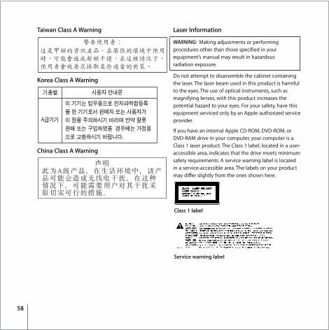
Taiwan Class A Warning
Korea Class A Warning
China Class A Warning
Laser Information
Do not attempt to disassemble the cabinet containing the laser. The laser beam used in this product is harmful to the eyes. The use of optical instruments, such as magnifying lenses, with this product increases the potential hazard to your eyes. For your safety, have this equipment serviced only by an Apple-authorized service provider.
If you have an internal Apple CD-ROM, DVD-ROM, or DVD-RAM drive in your computer, your computer is a Class 1 laser product. The Class 1 label, located in a user-accessible area, indicates that the drive meets minimum safety requirements. A service warning label is located in a service-accessible area. The labels on your product may differ slightly from the ones shown here.
WARNING: Making adjustments or performing procedures other than those specified in your equipment’s manual may result in hazardous radiation exposure.
Class 1 label
Service warning label

59
High-Risk Activities WarningThis computer system is not intended for use in the operation of nuclear facilities, aircraft navigation or communications systems, or air traffic control machines, or for any other uses where the failure of the computer system could lead to death, personal injury or severe environmental damage.
Disposal and Recycling InformationDispose of your Xserve and its battery according to your local environmental laws and guidelines.
For information about Apple’s recycling program, go to www.apple.com/environment.
European Union
The symbol above means that according to local laws and regulations your product should be disposed of separately from household waste. When this product reaches its end of life, take it to a collection point designated by local authorities. Some collection points accept products for free. The separate collection and recycling of your product at the time of disposal will help conserve natural resources and ensure that it is recycled in a manner that protects human health and the environment.
Battery Disposal InformationWhen replacing the internal battery, dispose of the spent battery according to your local environmental laws and guidelines.
California: The coin cell battery in your Xserve contains perchlorates. Special handling and disposal may apply. Refer to www.dtsc.ca.gov/hazardouswaste/perchlorate.
Nederlands: Gebruikte batterijen kunnen worden ingeleverd bij de chemokar of in een speciale batterijcontainer voor klein chemisch afval (kca) worden gedeponeerd.
Deutschland: Das Gerät enthält Batterien. Diese gehören nicht in den Hausmüll. Sie können verbrauchte Batterien beim Handel oder bei den Kommunen unentgeltlich abgeben.Um Kurzschlüsse zu vermeiden, kleben Sie die Pole der Batterien vorsorglich mit einem Klebestreifen ab.
Taiwan: