yamada ndp0515 en
TRANSCRIPT

Doc. No NDP05/15 English - 02 Revised June 2006
MAINTENANCE MANUAL YAMADA AIR-OPERATED DIAPHRAGM PUMPS NDP-05 NDP-15
WARNING
• For your own safety, be sure to read these procedures carefully before performing maintenance on this product. After reading this document, be sure to keep it handy for future reference.
These maintenance manuals covers what you should know about maintenance of the Yamada NDP-05 series and NDP-15 series Diaphragm Pumps. This edition is based on the standards for the June 1998 production run. Remember, the specifications are always subject to change; therefore, some of the information in this edition may not apply to new specifications. • Warnings and Cautions For safe use of this product, be sure to note the following: In this document, warnings and cautions are indicated by symbols. These symbols are for those who will operate this product and for those who will be nearby, for safe operation and for prevention of personal injury and property damage. The following warning and caution symbols have the meanings described below. Be sure to remember their meanings.
WARNING:
If you ignore the warning described and operate the product in an improper manner, there is danger of serious bodily injury or death.
CAUTION: If you ignore the caution described and operate the product in an improper manner, there is danger of personal injury or property damage.
Furthermore, to indicate the type of danger and damage, the following symbols are also used along with those mentioned above:
This symbol indicates a DON’T, and will be accompanied by an explanation on something you must not do.
This symbol indicates a DO, and will be accompanied by instructions on something you must do in a certain situation.
WARNING • Before starting maintenance work, cut off the feed air and clean the pump. If air pressure or residue
remain in the pump, there is danger of explosion, or possible poisoning resulting in serious injury or death if chemicals adhere to the skin or are accidentally swallowed. (For details on cleaning the pump, refer to Chapter 6 of the operating manual.)
• When replacing parts, be sure to use the recommended genuine parts or equivalents. Use of other
parts may cause a malfunction of the product.
CAUTION
• When it is instructed that special tools must be used, be sure to use the specified tools. Otherwise, the pump may be damaged.
• Refer to 10.1 “Specifications” in the Operating Manual. Also, remember that the pumps is
st be taken when lifting it. heavy, and extreme care mu
2
Table of Contents . Warnings and Cautions...................................................................................................................... 1 . Table of Contents............................................................................................................................... 2 1. Principles of operation .................................................................................................................... 4 2. Tools, etc
2.1 General tools ............................................................................................................................ 4 2.2 Special tools ............................................................................................................................. 4 2.3 Misc.......................................................................................................................................... 4
3. Ordering Replacement Parts ........................................................................................................... 4 4. Balls and Valve Seats 4.1 Removal g FAT, FST, BA , BS types ................................................................................................ 5 g FP , FDT, FV , FTT, FXT types......................................................................................... 6 4.2 Checking g Ball valve types ..................................................................................................................... 7 g Flat valve types Installation................................................................................................... 7 4.3 Installation................................................................................................................................. 7 5. Diaphragm and Centre Rod 5.1 Removal g FAT, FST, BA , BS types ................................................................................................ 8 g FP , FDT, FV , FTT, FXT types......................................................................................... 9 5.2 Checking ................................................................................................................................... 9 5.3 Installation g B H, B S, FPH, FPS types .............................................................................................. 10 g B C, B E, B N, B T, FPC, FPN, FPE, F T types ...................................................... 10 6. Pilot valve, Guide and Bushing 6.1 Removal g NDP-5.................................................................................................................................. 11 g NDP-15................................................................................................................................ 11 6.2 Checking ................................................................................................................................. 11 6.3 Installation............................................................................................................................... 11 7. Seal ring and sleeve 7.1 Removal .................................................................................................................................. 12 7.2 Checking ................................................................................................................................. 12 7.3 Installation............................................................................................................................... 12 8. Exploded View and Parts List........................................................................................................... 8.1 NDP-05-FAT, FST ................................................................................................................. 13 8.2 NDP-05-FPT, FDT, FVT........................................................................................................ 15 8.3 NDP-05-FTT, FXT ................................................................................................................ 17 8.4 NDP-15-BA , BS ............................................................................................................... 20 8.5 NDP-15-FP , FDT, FV ..................................................................................................... 23 8.6 NDP-15-FTT, FXT ................................................................................................................. 25

3
9 Diaphragm kits, valve kits, air motor kits, air motor seal kits NDP-05………………………………………………………………………………………19 NDP-15………………………………………………………………………………………27
4
1. Principles of operation
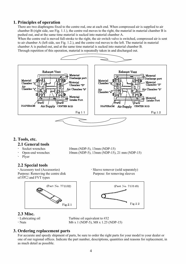
There are two diaphragms fixed to the centre rod, one at each end. When compressed air is supplied to air chamber B (right side, see Fig. 1.1.), the centre rod moves to the right, the material in material chamber B is pushed out, and at the same time material is sucked into material chamber A. When the centre rod is moved full-stroke to the right, the air switch valve is switched, compressed air is sent to air chamber A (left side, see Fig. 1.2.), and the centre rod moves to the left. The material in material chamber A is pushed out, and at the same time material is sucked into material chamber B. Through repetition of this operation, material is repeatedly taken in and discharged out.
2. Tools, etc. 2.1 General tools Socket wrenches 10mm (NDP-5), 13mm (NDP-15) Open-end wrenches 10mm (NDP-5), 13mm (NDP-15), 21 mm (NDP-15) Plyer 2.2 Special tools Accessory tool (Accessories) Sleeve remover (sold separately) Purpose: Removing the centre disk Purpose: for removing sleeves of FP and FVT types
2.3 Misc. Lubricating oil Turbine oil equivalent to #32 Nuts M6 x 1 (NDP-5), M8 x 1.25 (NDP-15)
3. Ordering replacement parts
For accurate and speedy shipment of parts, be sure to order the right parts for your model to your dealer or one of our regional offices. Indicate the part number, descriptions, quantities and reasons for replacement, in as much detail as possible.
5
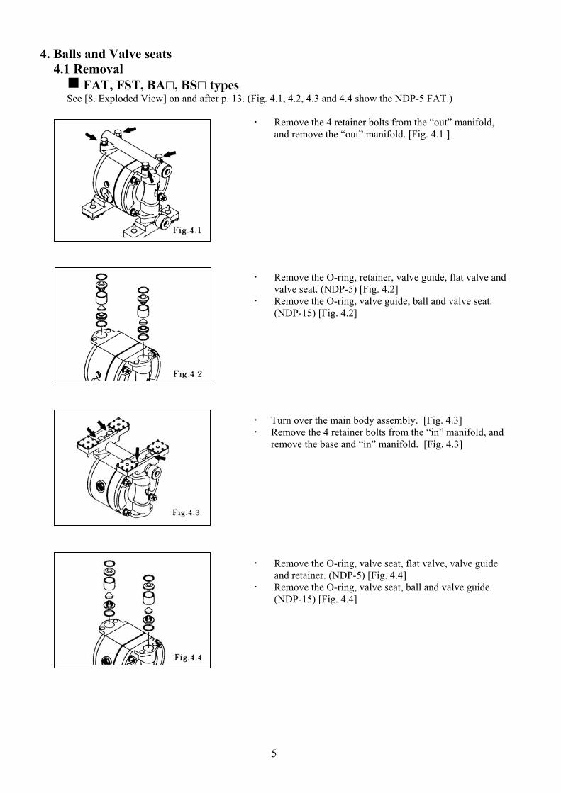
4. Balls and Valve seats 4.1 Removal g FAT, FST, BA , BS types See [8. Exploded View] on and after p. 13. (Fig. 4.1, 4.2, 4.3 and 4.4 show the NDP-5 FAT.)
Remove the 4 retainer bolts from the “out” manifold, and remove the “out” manifold. [Fig. 4.1.]
Remove the O-ring, retainer, valve guide, flat valve and valve seat. (NDP-5) [Fig. 4.2]
Remove the O-ring, valve guide, ball and valve seat. (NDP-15) [Fig. 4.2]
Turn over the main body assembly. [Fig. 4.3] Remove the 4 retainer bolts from the “in” manifold, and
remove the base and “in” manifold. [Fig. 4.3]
Remove the O-ring, valve seat, flat valve, valve guide and retainer. (NDP-5) [Fig. 4.4]
Remove the O-ring, valve seat, ball and valve guide. (NDP-15) [Fig. 4.4]

6
g FP , FDT, FVT types See [8. Exploded View] on and after p. 13. (Fig. 4.5, 4.6, 4.7 and 4.8 show the NDP-5 FPT.)
Remove the 4 retainer nuts from the out manifold, and remove the “out” manifold. [Fig. 4.5]
<NOTE> When the retainer nuts on both sides of the tie rod are
removed, the “in” manifold can be removed. (NDP-5)
Remove the O-ring, retainer, flat valve and valve seat. [Fig. 4.6]
Turn over the main body assembly. [Fig. 4.7] Pull out the bolt, and remove the base and “in”
manifold. (NDP-5)
Remove the 4 retainer bolts from the “in” manifold, and remove the base and “in” manifold. (NDP-15) [Fig. 4.7]
Remove the O-ring, valve seat, and flat valve. (NDP-5)
[Fig. 4.8] Remove the O-ring, valve seat, flat valve and valve
guide. (NDP-15) [Fig. 4.8]

7
4.2 Checking g Ball valve type
Ball [Fig. 4.9]
Measure the outside diameter, and if it is outside the usable range, replace the ball.
Usable range of Ball
NDP-15 S ø 20.0 ~ S ø 22.8 mm
Valve seat [Fig. 4.10] Measure the dimension shown at left, and if it is outside the usable range, replace the valve seat.
Usable range of Valve seat
NDP-15 2.6 ~ 6.5 mm
g Flat valve type
Flat valve [Fig. 4.11] Measure the dimension shown at left, and if it is outside
the usable range, replace the seat. If the seal ring is worn out or cracked, replace it.
Usable range of Flat valve
NDP-05 2.5 ~ 3.1 mm NDP-15 4.3 ~ 5.0 mm
Valve seat [Fig. 4.12]
Measure the dimension shown at left, and if it is outside the usable range, replace the seat.
Usable range of Valve seat
NDP-05 5.8 ~ 7.1 mm NDP-15 8.2 ~ 10.0 mm
O-ring (other than PTFE)
If O-rings are worn out or cracked, replace them.
4.3 Installation For installation, see [8. Exploded View] on and after p. 13, and install in the reverse order of disassembly.
Tightening torque for manifold retainer bolts or nuts
NDP-05 7.5 N m{75kgf cm} NDP-15 12 N m{120kgf cm}
<NOTE> Make sure there is no dust on the seal surface and the
seal is not damaged. Replace the PTFE O-ring regardless of its condition.

8
5. Diaphragm and Centre rod 5.1 Removal g FAT, FST, BA , BS types See [8. Exploded View] on and after p.13. (Fig. 5.1, 5.2, and 5.3 show the NDP-5 FAT.)
Remove the ball or flat valve and valve seat. (see [4.1 removal FAT, FST, BA , BS , types] on p.4)
Remove the 4 (6 on the NDP-15) retainer bolts from the “out” chamber, and remove the “out” chamber. [Fig. 5.1]
Remove the nuts on both sides of the centre rod. [Fig. 5.2]
After the nuts on one side have been removed, remove the centre disk and diaphragm. Remove the diaphragm, centre disk and centre rod from the opposite side of the main body.
<NOTE> When the diaphragms are removed, the main body is
separated into 2 pieces. For easy work, leave the tie rods or bolts fastened temporarily before remove the diaphragms.
Remove the nuts on the opposite side using the double
nuts. [Fig. 5.3] Remove the coned disk spring, centre disk and
diaphragm.

9
g FP , FDT, FV , FTT, FXT types See [8. Exploded View] on and after p.13. (Fig. 5.4, 5.5 and 5.6 show the NDP-5 FPT.)
Remove the flat valve and valve seat (see [4.1 Removal FP , FV , FTT, FXT types] on p.5)
Remove the 4 (6 on the NDP-15) retainer nuts from the “out” chamber, and remove the “out” chamber. [Fig. 5.4]
Remove the centre disk from one side using the accessory tool (special tool: Part No. 771132) (NDP-5). [Fig. 5.5]
Remove the centre disk from one side. (NDP-15) [Fig. 5.5]
After the centre disk (outside) has been removed, remove the diaphragm and the centre disk (inside).
Remove the centre disk and centre rod from the opposite side of the main body.
<NOTE> When the diaphragms are removed, the main body is
separated into 2 pieces. For easy work, leave bolts fastened temporarily before remove the diaphragms.
Remove the centre disk and diaphragm from the
opposite side using the double nut. [Fig. 5.6]
5.2 Checking Diaphragm
If the diaphragm is worn out or damaged, replace it.
Guideline of diaphragm life NDP-05 PTFE 30,000,000 strokes NDP-15 CR, NBR, PTFE, EPDM 10,000,000 strokes
TPEE, TPO 15,000,000 strokes Centre rod [Fig. 5.7]
Measure the diameter, and if it is outside the usable range, replace the centre rod.
Usable range of centre rod
NDP-05 ø 9.95 ~ ø 10.0mm NDP-15 ø 13.96 ~ ø 14.0mm

10
5.3 Installation g B H, B S, FPH, FPS types For installation, see [8. Exploded View] on and after p.13, and install in the reverse order of disassembly.
Apply lubricating oil to the centre rod, and insert it into the main body. B H, B S, FPH, FPS
Keep the convex side to the outside. Tighten the centre disk using the open-end wrenches for
the NDP-15 FP . (No coned disk springs and nuts are needed.)
Tighten the out chamber temporarily at first. After installation of the out chambers on both sides,
place the pump on a flat surface and stand the pump upright for further assembly.
Tightening torque for centre rod and out chamber
NDP-05 7.5 N m {75 kgf cm} NDP-15 12 N m {120 kgf cm}
<NOTE> Make sure there is no dust on the seal surface in order
to prevent seal damage. Tighten the bolts so that the balance is equal from both
sides on diagonal line with even torque.
gB C, B N, B T, FPC, FPN, F T, types For installation, see [8. Exploded View] on and after p. 13, and install in the reverse order of disassembly.
B C, B E, B N, B T, FPC, FPN, F E, F T Apply lubricating oil to the centre rod, and insert it into
the main body. Keep the marking “LIQUID” to liquid end for CR,
EPDM, NBR diaphragms. Keep the convex side to the outside for PTFE
diaphragm. Install the O-ring (cf. Fig. 5.9). Tighten the centre disk using the accessory tool (special
tool: Part No. 771132) for the NDP-5 FPT, FVT. Tighten the centre disk using the open-end wrenches for
the NDP-15 FP , FVT. (No coned disk springs and nuts are needed.) After installation of the “out” chambers on both sides,
place the pump on a flat surface and stand the pump upright for further assembly.
Tightening torque for centre rod and out chamber NDP-05 7.5 N m {75 kgf cm} NDP-15 12 N m {120 kgf cm}
<NOTE> Make sure there is no dust on the seal surface in order
to prevent seal damage. Replace the PTFE O-ring by new one. Tighten the bolts so that the balance is equal from both
sides on diagonal line with even torque.

11
6. Pilot valve, Guide and Bushing 6.1 Removal g NDP-5 See [8. Exploded View] on and after p. 13.
Remove the diaphragm and centre rod (see [5.1 Removal] on p. 7).
Remove the main body. [Fig. 6.1] Draw out the pilot valve assembly. [Fig. 6.1] Remove the O-ring and bushing. [Fig. 6.1]
g NDP-15 See [8. Exploded View] on an after p.13.
Remove the diaphragm and centre rod (see [5.1 Removal] on p. 7). Remove the body B. [Fig. 6.2] Draw out the pilot valve assembly. [Fig. 6.2] Remove the O-ring, bushing and guide. [Fig. 6.2]
6.2 Checking Bushing (NDP-5) [Fig. 6.3]
Measure the inside diameter, and if it is outside the usable range, replace the bushing.
Usable range of bushing
ø 10.1 ~ ø 10.3mm
Guide (NDP-15) [Fig. 6.4] Measure the inside diameter, and if it is outside the usable range, replace the guide.
Usable range of guide ø 14.1 ~ ø 14.2mm
O-rings If the O-ring is worn out or cracked, replace it.
Pilot valve assembly If the pilot valve is worn out or cracked, replace it.
6.3 Installation For installation, see [8. Exploded View] on and after p. 13, and install in the reverse order of disassembly.
<NOTE> Make sure there is no dust on the seal surface and the
seal is not damaged.

12
7. Seal ring and sleeve 7.1 Removal See [8. Exploded View] on and after p. 13. (Fig. 7.1, 7.2 and 7.3 show the NDP-5 FAT.)
Remove the cap using the Accessory tool (special tool: Part No. 771132). [Fig. 7.1]
Draw out the C spool valve assembly using the plyer,
and remove the seal ring from the C spool valve assembly. [Fig. 7.2]
Remove the sleeve using the sleeve remover (special tool: Part number 713148). [Fig. 7.3]
7.2 Checking
Seal ring [Fig. 7.4] Measure the inside thick diameter, and if it is outside the usable range, replace the seal ring. If the seal ring is worn out or cracked, replace it.
Usable range of seal ring NDP-05 1.40 ~ 1.45 mm NDP-15 1.85 ~ 1.90 mm
Sleeve [Fig. 7.5]
Measure the inside diameter, and if it is outside the usable range, replace the sleeve.
Usable range of Sleeve
NDP-05 ø 9.5 ~ ø 9.55 mm NDP-15 ø 15.8 ~ ø 15.85 mm
O-rings
If the O-ring is worn out or cracked, replace it. 7.3 Installation
For installation see [8. Exploded View] on and after p.13, and install in the reverse order of disassembly. <NOTE> Make sure there is no dust on the seal surface and it is
not damaged.

13
8.1 Exploded view NDP-05-FAT, FST

14
PARTS LIST NDP-05-FAT,FST No. F A T No. F S T DESCRIPTIONS Q’TY 1 682-528 1 682-528 BOLT 4 2 683-391 2 683-391 NUT 4 3 681-855 3 681-855 SPRING WASHER 16 4 631-328 4 631-328 WASHER 16 5 709-470 5 831-274 MANIFOLD 2 6 802-047 6 802-048 BODY ASSY 1 6-1 640-139 6-1 640-139 O-RING 2 6-2 771-093 6-2 771-093 DIAPHRAGM 2 6-3 709-477 6-3 709-476 CENTRE DISC 2 6-4 643-003 6-4 643-003 O-RING 4 6-5 683-391 6-5 683-391 NUT 2 6-6 684-915 6-6 684-915 WASHER 2 6-7 709-317 6-7 709-317 CENTRE DISC 2 6-8 780-000 6-8 780-000 BODY 1 6-9 640-007 6-9 640-007 O-RING 2 6-10 771-088 6-10 771-088 BUSHING 1 6-11 771-980 6-11 771-980 GASKET 1 6-12 780-001 6-12 780-001 BODY 1 6-13 709-316 6-13 709-316 CENTRE ROD 1 6-14 771-239 6-14 771-239 CUSHION 2 6-15 640-017 6-15 640-017 O-RING 1 6-16 802-386 6-16 802-386 SPOOL ASSY 1 6-18 803-214 6-18 803-214 SLEEVE ASSY 1 6-18-1 771-097 6-18-1 771-097 O-RING 6 6-19 771-096 6-19 771-096 CUSHION 1 6-20 771-465 6-20 771-465 SILENCER 1 6-21 771-589 6-21 771-589 MESH 1 6-22 771-100 6-22 771-100 CAP 1 6-23 771-099 6-23 771-099 RESET BUTTON 1 6-24 640-002 6-24 640-002 O-RING 1 6-25 709-319 6-25 709-319 SPRING 2 6-27 803-510 6-27 803-510 PILOT VALVE ASSY 2 6-27-1 713-445 6-27-1 713-445 PILOT VALVE 1 6-27-2 712-971 6-27-2 712-971 SPRING 1 6-27-3 771-553 6-27-3 771-553 PACKING 1 6-28 771-095 6-28 771-095 STOPPER 1 7 643-015 7 643-015 O-RING 4 8 709-634 8 709-634 RETAINER 4 9 709-635 9 709-635 VALVE GUIDE 4 10 771-133 10 771-133 O-RING 4 11 771-152 11 771-152 FLAT VALVE 4 12 709-637 12 709-637 VALVE SEAT 4 13 709-469 13 709-467 PUMP CHAMBER 2 14 681-292 14 681-292 BALL VALVE 1 15 621-103 15 621-103 BOLT 8 16 771-101 16 771-101 BASE 2 17 771-102 17 771-102 CUSHION 4

15
8.2 Exploded view NDP-05-FPT,FDT, FVT
16
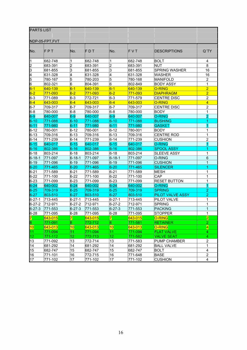
PARTS LIST NDP-05-FPT,FVT No. F P T No. F D T No. F V T DESCRIPTIONS Q`TY 1 682-748 1 682-748 1 682-748 BOLT 4 2 683-391 2 683-391 2 683-391 NUT 8 3 681-855 3 681-855 3 681-855 SPRING WASHER 16 4 631-328 4 631-328 4 631-328 WASHER 16 5 780-167 5 780-203 5 780-168 MANIFOLD 2 6 802-321 6 804-391 6 802-849 BODY ASSY 1 6-1 640-139 6-1 640-139 6-1 640-139 O-RING 2 6-2 771-093 6-2 771-093 6-2 771-093 DIAPHRAGM 2 6-3 771-089 6-3 772-721 6-3 771-579 CENTRE DISC 2 6-4 643-003 6-4 643-003 6-4 643-003 O-RING 4 6-7 709-317 6-7 709-317 6-7 709-317 CENTRE DISC 2 6-8 780-000 6-8 780-000 6-8 780-000 BODY 1 6-9 640-007 6-9 640-007 6-9 640-007 O-RING 2 6-10 771-088 6-10 771-088 6-10 771-088 BUSHING 1 6-11 771-980 6-11 771-980 6-11 771-980 GASKET 1 6-12 780-001 6-12 780-001 6-12 780-001 BODY 1 6-13 709-316 6-13 709-316 6-13 709-316 CENTRE ROD 1 6-14 771-239 6-14 771-239 6-14 771-239 CUSHION 2 6-15 640-017 6-15 640-017 6-15 640-017 O-RING 1 6-16 802-386 6-16 802-386 6-16 802-386 SPOOL ASSY 1 6-18 803-214 6-18 803-214 6-18 803-214 SLEEVE ASSY 1 6-18-1 771-097 6-18-1 771-097 6-18-1 771-097 O-RING 6 6-19 771-096 6-19 771-096 6-19 771-096 CUSHION 1 6-20 771-465 6-20 771-465 6-20 771-465 SILENCER 1 6-21 771-589 6-21 771-589 6-21 771-589 MESH 1 6-22 771-100 6-22 771-100 6-22 771-100 CAP 1 6-23 771-099 6-23 771-099 6-23 771-099 RESET BUTTON 1 6-24 640-002 6-24 640-002 6-24 640-002 O-RING 1 6-25 709-319 6-25 709-319 6-25 709-319 SPRING 2 6-27 803-510 6-27 803-510 6-27 803-510 PILOT VALVE ASSY 2 6-27-1 713-445 6-27-1 713-445 6-27-1 713-445 PILOT VALVE 1 6-27-2 712-971 6-27-2 712-971 6-27-2 712-971 SPRING 1 6-27-3 771-553 6-27-3 771-553 6-27-3 771-553 PACKING 1 6-28 771-095 6-28 771-095 6-28 771-095 STOPPER 1 7 643-015 7 643-015 7 643-015 O-RING 2 8 771-091 8 772-712 8 771-581 RETAINER 2 10 643-013 10 643-013 10 643-013 O-RING 4 11 771-094 11 771-094 11 771-094 FLAT VALVE 4 12 771-112 12 772-713 12 771-582 VALVE SEAT 4 13 771-092 13 772-714 13 771-583 PUMP CHAMBER 2 14 681-292 14 681-292 14 681-292 BALL VALVE 1 15 682-747 15 682-747 15 682-747 BOLT 4 16 771-101 16 772-715 16 771-648 BASE 2 17 771-102 17 771-102 17 771-102 CUSHION 4

17
8.3 Exploded view NDP-05-FTT, FXT

18
PARTS LIST NDP-05-FTT,FXT No. F T T No. F X T DESCRIPTIONS Q`TY 1 000-109 1 000-109 THREAD END 4 2 000-091 2 000-091 CAP NUT 4 3 681-855 3 681-855 SPRING WASHER 12 4 000-069 4 000-069 WASHER 16 5 02-0065 5 000-103 MANIFOLD 2 6 6 BODY ASSY 1 6-1 640-139 6-1 640-139 O-RING 2 6-2 771-093 6-2 771-093 DIAPHRAGM 2 6-3 780-121 6-3 780-121 CENTRE DISC 2 6-4 643-003 6-4 643-003 O-RING 4 6-7 709-317 6-7 709-317 CENTRE DISC 2 6-8 780-000 6-8 780-000 BODY 1 6-9 640-007 6-9 640-007 O-RING 2 6-10 771-088 6-10 771-088 BUSHING 1 6-11 771-980 6-11 771-980 GASKET 1 6-12 780-001 6-12 780-001 BODY 1 6-13 709-316 6-13 709-316 CENTRE ROD 1 6-14 771-239 6-14 771-239 CUSHION 2 6-15 640-017 6-15 640-017 O-RING 1 6-16 802-386 6-16 802-386 SPOOL ASSY 1 6-18 803-214 6-18 803-214 SLEEVE ASSY 1 6-18-1 771-097 6-18-1 771-097 O-RING 6 6-19 771-096 6-19 771-096 CUSHION 1 6-20 771-465 6-20 771-465 SILENCER 1 6-21 771-589 6-21 771-589 MESH 1 6-22 771-100 6-22 771-100 CAP 1 6-23 771-099 6-23 771-099 RESET BUTTON 1 6-24 640-002 6-24 640-002 O-RING 1 6-25 709-319 6-25 709-319 SPRING 2 6-27 803-510 6-27 803-510 PILOT VALVE ASSY 2 6-27-1 713-445 6-27-1 713-445 PILOT VALVE 1 6-27-2 712-971 6-27-2 712-971 SPRING 1 6-27-3 771-553 6-27-3 771-553 PACKING 1 6-28 771-095 6-28 771-095 STOPPER 1 7 643-015 7 643-015 O-RING 2 8 02-0067 8 000-100 VALVE GUIDE 4 9 628-010 9 628-010 BOLT 12 10 643-013 10 643-013 O-RING 4 11 771-094 11 771-094 FLAT VALVE 4 12 02-0068 12 000-101 VALVE SEAT 4 13 02-0066 13 000-102 PUMP CHAMBER 2 14 681-292 14 681-292 BALL VALVE 1 15 000-110 15 000-110 THREAD END 4 16 710-586 16 710-586 BASE 2 17 000-551 17 000-551 STAND RUBBER 4 20 000-549 20 000-549 NUT 4 21 000-548 21 000-548 WASHER 4 22 000-550 22 000-550 BOLT 4

19
Service kits Diaphragm pumps (NDP-05) DIAPHRAGM KITS (FAT,FST,FPT,FDT,FVT,FTT,FXT)
No. DESCRIPTION K05D-MT Q`TY K05D-PT Q`TY 6-1 O-RING 640-139 2 640-139 2 6-2 DIAPHRAGM 771-093 2 771-093 2 6-4 O-RING 643-003 4 643-003 4 6-5 NUT 683-391 2 6-6 CONED DISC SPRING 684-915 2 7 O-RING 643-015 4 643-015 2 10 O-RING 643-013 2
VALVE KITS (FAT,FST,FDT,FPT,FVT,FTT,FXT)
No. DESCRIPTION K05V-AT/ST Q`TY K05V-PT Q`TY K05V-VT Q`TY K05V-TT Q`TY K05V-XT Q`TY
7 O-RING 643-015 4 643-015 2 643-015 2 643-015 2 643-015 2 8 VALVE GUIDE 709-634 4 771-091 2 771-581 2 02-0067 4 000-100 4 10 O-RING 771-133 4 643-013 4 643-013 4 643-013 4 643-013 4 11 FLAT VALVE 771-152 4 771-094 4 771-094 4 771-094 4 771-094 4 12 VALVE SEAT 709-637 4 771-112 4 771-582 4 02-0068 4 000-101 4
No. DESCRIPTION K05V-DT Q`TY 7 O-RING 643-015 2 8 VALVE GUIDE 772-712 2 10 O-RING 643-013 4 11 FLAT VALVE 771-094 4 12 VALVE SEAT 772-713 4
K05-AM AIR MOTOR KIT FOR NDP-5 K05-AMS AIR MOTOR SEAL KIT FOR NDP-5 NO. PART NO. DESCRIPTION K05-AM K05-AMS
6-9 640-007 O-RING 2 2 6-10 771-088 BUSHING 2 6-11 771-980 GASKET 1 1 6-15 640-017 O-RING 1 1 6-16 802-386 C SPOOL VALVE ASSEMBLY 1 6-18 771-097 O-RING 6 6-19 771-096 CUSHION 1 6-20 771-465 SILENCER 1 6-24 640-002 O-RING 1 1 6-25 709-319 SPRING 2 6-27 803-510 PILOT VALVE ASSEMBLY 2 6-27* 771-553 PACKING 2 NOTE) *771553 PAKING IS A PART OF 803510 PILOT VALVE ASSEMBLY
20
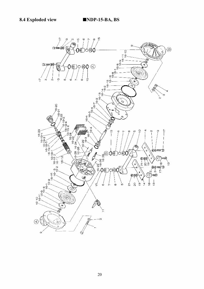
8.4 Exploded view NDP-15-BA, BS

21
PARTS LIST NDP-15-BA.. B A C B A T No. B A N No. B A E DESCRIPTIONS Q`TY B A H B A S 1 683-171 1 683-171 BOLT 6 2 631-329 2 631-329 WASHER 20 3 681-300 3 681-300 SPRING WASHER 14 4 628-012 4 628-012 NUT 6 5C 640-025 5T 643-025 O-RING 4 N 640-025 E 684-114 O-RING 4 H 643-025 S 684-114 O-RING 4 6 771-523 6 771-523 BALL GUIDE 4 7C 771-526 7T 771-524 BALL 4 N 771-525 E 771-979 BALL 4 H 771-524 S 771-979 BALL 4 8 711-227 8 711-227 VALVE SEAT 4 9 711-226 9 711-226 PUMP CHAMBER 2 10 802-707 10 802-707 MANIFOLD 2 11 681-292 11 681-292 BALL VALVE 1 13 621-102 13 621-102 BOLT 4 14 711-405 14 711-405 BASE 2 15C 640-130 15T 643-130 O-RING 4 N 640-130 E 684-113 O-RING 4 H 643-130 S 684-113 O-RING 4 16 02-0010 16 02-0010 BODY ASSY 1 16-1C 770-971 16-1T 770-933 DIAPHRAGM 2 N 770-973 E 771-848 DIAPHRAGM 2 H 771-372 S 771-972 DIAPHRAGM 2 16-2 640-144 16-2 640-144 O-RING 2 16-3 640-020 16-3 640-020 O-RING 2 16-4 640-013 16-4 640-013 O-RING 2 16-5 771-337 16-5 771-337 GUIDE 1 16-6 710-578 16-6 710-578 CENTRE ROD 1 16-7 771-336 16-7 771-336 BUSHING 2 16-8C 640-005 16-8T 643-005 O-RING 4 N 640-005 E O-RING 4 H S O-RING 4 16-9 708-770 16-9 708-770 CENTRE DISC 2 16-10 681-849 16-10 681-849 NUT 2 16-11 684-916 16-11 684-916 WASHER 2 16-12 780-028 16-12 780-028 BODY 1 16-13 771-347 16-13 771-347 GASKET 1 16-14 780-030 16-14 780-030 BODY 1 16-15 771-342 16-15 771-342 CUSHION 2 16-16 771-344 16-16 771-344 CENTRE DISC 2 16-17 771-483 16-17 771-483 CUSHION 1 16-18 683-089 16-18 683-089 SLEEVE ASSY 1 16-18-1 683-123 16-18-1 683-123 O-RING 6 16-19 802-835 16-19 802-835 SPOOL ASSY 1 16-20 771-695 16-20 771-695 CAP 1 16-21 640-022 16-21 640-022 O-RING 1 16-22 771-350 16-22 771-350 RESET BUTTON 1 16-23 640-002 16-23 640-002 O-RING 1 16-24 771-589 16-24 771-589 MESH 2 16-25 771-465 16-25 771-465 SILENCER 1 16-26 832-141 16-26 832-141 PILOT VALVE ASSY 2 16-28 710-577 16-28 710-577 SPRING 2 16-29 632-753 16-29 632-753 SPRING PIN 2 17 682-727 17 682-727 BOLT 8 18 771-123 18 771-123 STAND RUBBER 4 19 631-328 19 631-328 WASHER 4 20 681-855 20 681-855 SPRING WASHER 4 21 628-010 21 628-010 NUT 4
22
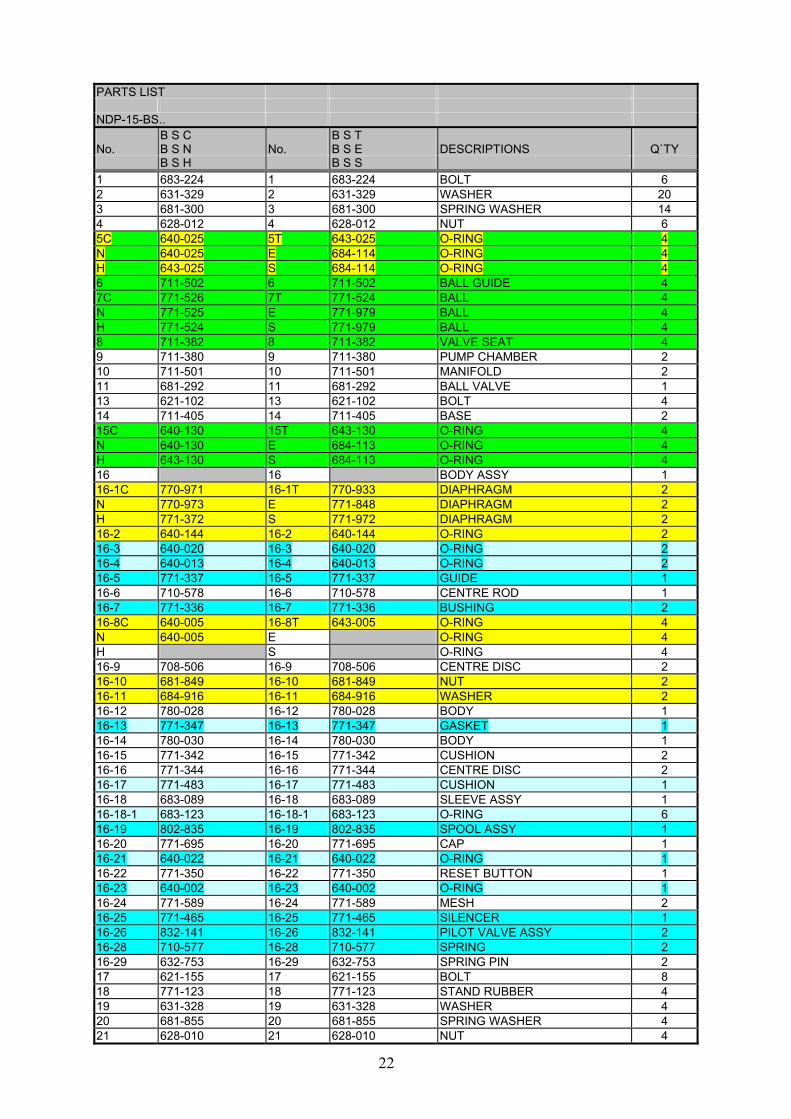
PARTS LIST NDP-15-BS.. B S C B S T No. B S N No. B S E DESCRIPTIONS Q`TY B S H B S S 1 683-224 1 683-224 BOLT 6 2 631-329 2 631-329 WASHER 20 3 681-300 3 681-300 SPRING WASHER 14 4 628-012 4 628-012 NUT 6 5C 640-025 5T 643-025 O-RING 4 N 640-025 E 684-114 O-RING 4 H 643-025 S 684-114 O-RING 4 6 711-502 6 711-502 BALL GUIDE 4 7C 771-526 7T 771-524 BALL 4 N 771-525 E 771-979 BALL 4 H 771-524 S 771-979 BALL 4 8 711-382 8 711-382 VALVE SEAT 4 9 711-380 9 711-380 PUMP CHAMBER 2 10 711-501 10 711-501 MANIFOLD 2 11 681-292 11 681-292 BALL VALVE 1 13 621-102 13 621-102 BOLT 4 14 711-405 14 711-405 BASE 2 15C 640-130 15T 643-130 O-RING 4 N 640-130 E 684-113 O-RING 4 H 643-130 S 684-113 O-RING 4 16 16 BODY ASSY 1 16-1C 770-971 16-1T 770-933 DIAPHRAGM 2 N 770-973 E 771-848 DIAPHRAGM 2 H 771-372 S 771-972 DIAPHRAGM 2 16-2 640-144 16-2 640-144 O-RING 2 16-3 640-020 16-3 640-020 O-RING 2 16-4 640-013 16-4 640-013 O-RING 2 16-5 771-337 16-5 771-337 GUIDE 1 16-6 710-578 16-6 710-578 CENTRE ROD 1 16-7 771-336 16-7 771-336 BUSHING 2 16-8C 640-005 16-8T 643-005 O-RING 4 N 640-005 E O-RING 4 H S O-RING 4 16-9 708-506 16-9 708-506 CENTRE DISC 2 16-10 681-849 16-10 681-849 NUT 2 16-11 684-916 16-11 684-916 WASHER 2 16-12 780-028 16-12 780-028 BODY 1 16-13 771-347 16-13 771-347 GASKET 1 16-14 780-030 16-14 780-030 BODY 1 16-15 771-342 16-15 771-342 CUSHION 2 16-16 771-344 16-16 771-344 CENTRE DISC 2 16-17 771-483 16-17 771-483 CUSHION 1 16-18 683-089 16-18 683-089 SLEEVE ASSY 1 16-18-1 683-123 16-18-1 683-123 O-RING 6 16-19 802-835 16-19 802-835 SPOOL ASSY 1 16-20 771-695 16-20 771-695 CAP 1 16-21 640-022 16-21 640-022 O-RING 1 16-22 771-350 16-22 771-350 RESET BUTTON 1 16-23 640-002 16-23 640-002 O-RING 1 16-24 771-589 16-24 771-589 MESH 2 16-25 771-465 16-25 771-465 SILENCER 1 16-26 832-141 16-26 832-141 PILOT VALVE ASSY 2 16-28 710-577 16-28 710-577 SPRING 2 16-29 632-753 16-29 632-753 SPRING PIN 2 17 621-155 17 621-155 BOLT 8 18 771-123 18 771-123 STAND RUBBER 4 19 631-328 19 631-328 WASHER 4 20 681-855 20 681-855 SPRING WASHER 4 21 628-010 21 628-010 NUT 4

23
8.5 Exploded view NDP-15-FP., FD., FV.

24
PARTS LIST NDP-15-FP.,FD.,FV.. F P C F P T F V T No. F P N No. F P E No. F D T No. DESCRIPTIONS Q`TY F P H F P S F V S 1 684-310 1 684-310 1 684-310 1 684-310 BOLT 6 2 631-329 2 631-329 2 631-329 2 631-329 WASHER 18 3 681-300 3 681-300 3 681-300 3 681-300 SPRING WASHER 18 4 628-012 4 628-012 4 628-012 4 628-012 NUT 24 5C 640-027 5T 643-027 5T 643-027 5T 643-027 O-RING 8 N 640-027 E 684-115 O-RING 8 H 643-027 S 684-115 S 684-115 O-RING 8 6 771-341 6 771-341 6 772-718 6 771-632 VALVE GUIDE 4 7 771-340 7 771-340 7 771-340 7 771-340 FLAT VALVE 4 8 771-345 8 771-345 8 772-719 8 771-633 VALVE SEAT 4 9 780-119 9 780-119 9 780-199 9 780-120 PUMP CHAMBER 2 10 780-078 10 780-078 10 780-204 10 780-169 MANIFOLD 2 11 681-292 11 681-292 11 681-292 11 681-292 BALL VALVE 1 13 621-153 13 621-153 13 621-153 13 621-153 BOLT 4 14 771-352 14 771-352 14 772-720 14 771-635 BASE 2 16 16 16 16 BODY ASSY 1 16-1C 770-971 16-1T 770-933 16-1T 770-933 16-1T 770-933 DIAPHRAGM 2 N 770-973 E 771-848 DIAPHRAGM 2 H 771-372 S 771-972 S 771-972 DIAPHRAGM 2 16-2 640-144 16-2 640-144 16-2 640-144 16-2 640-144 O-RING 2 16-3 640-020 16-3 640-020 16-3 640-020 16-3 640-020 O-RING 2 16-4 640-013 16-4 640-013 16-4 640-013 16-4 640-013 O-RING 2 16-5 771-337 16-5 771-337 16-5 771-337 16-5 771-337 GUIDE 1 16-6 710-578 16-6 710-578 16-6 710-578 16-6 710-578 CENTRE ROD 1 16-7 771-336 16-7 771-336 16-7 771-336 16-7 771-336 BUSHING 2 16-8C 640-005 16-8T 643-005 16-8T 643-005 16-8T 643-005 O-RING 4 N 640-005 E E O-RING 4 H S S S O-RING 4 16-9 770-968 16-9 770-968 16-9 772-722 16-9 771-631 CENTRE DISC 2 16-12 780-028 16-12 780-028 16-12 780-028 16-12 780-028 BODY 1 16-13 771-347 16-13 771-347 16-13 771-347 16-13 771-347 GASKET 1 16-14 780-030 16-14 780-030 16-14 780-030 16-14 780-030 BODY 1 16-15 771-342 16-15 771-342 16-15 771-342 16-15 771-342 CUSHION 2 16-16 771-344 16-16 771-344 16-16 771-344 16-16 771-344 CENTRE DISC 2 16-17 771-483 16-17 771-483 16-17 771-483 16-17 771-483 CUSHION 1 16-18 683-089 16-18 683-089 16-18 683-089 16-18 683-089 SLEEVE ASSY 1 16-18-1 683-123 16-18-1 683-123 16-18-1 683-123 16-18-1 683-123 O-RING 6
16-19 802-835 16-19 802-835 16-19 802-835 16-19 802-835 SPOOL ASSY 1 16-20 771-695 16-20 771-695 16-20 771-695 16-20 771-695 CAP 1 16-21 640-022 16-21 640-022 16-21 640-022 16-21 640-022 O-RING 1 16-22 771-350 16-22 771-350 16-22 771-350 16-22 771-350 RESET BUTTON 1 16-23 640-002 16-23 640-002 16-23 640-002 16-23 640-002 O-RING 1 16-24 771-589 16-24 771-589 16-24 771-589 16-24 771-589 MESH 2 16-25 771-465 16-25 771-465 16-25 771-465 16-25 771-465 SILENCER 1 16-26 832-141 16-26 832-141 16-26 832-141 16-26 832-141 PILOT VALVE ASSY 2 16-28 710-577 16-28 710-577 16-28 710-577 16-28 710-577 SPRING 2 16-29 632-753 16-29 632-753 16-29 632-753 16-29 632-753 SPRING PIN 2 18 770-551 18 770-551 18 770-551 18 770-551 STAND RUBBER 4
*NOTE FD PUMPS CAN ALSO BE PROVIDE WITH DIFFERENT DIAPHRAGMS

25
8.6 Exploded view NDP-15-FTT, FXT

26
PARTS LIST NDP-15-FTT,FXT No. F T T No. F X T DESCRIPTIONS Q`TY 1 000-111 1 000-111 THREAD END 6 2 631-328 2 631-328 WASHER 8 3 681-855 3 681-855 SPRING WASHER 4 4 000-091 4 000-091 CAP NUT 4 5 643-027 5 643-027 O-RING 8 6 02-0040 6 000-104 VALVE GUIDE 4 7 771-340 7 771-340 FLAT VALVE 4 8 02-0042 8 000-105 VALVE SEAT 4 9 02-0041 9 000-106 PUMP CHAMBER 2 10 02-0039 10 000-107 MANIFOLD 2 11 681-292 11 681-292 BALL VALVE 1 13 621-153 13 621-153 BOLT 4 14 000-080 14 000-080 STANDSTRIP 2 15 000-983 15 000-983 PROTECTOR PLATE 2 16 16 BODY ASSY 1 16-1 770-933 16-1 770-933 DIAPHRAGM 2 16-2 640-144 16-2 640-144 O-RING 2 16-3 640-020 16-3 640-020 O-RING 2 16-4 640-013 16-4 640-013 O-RING 2 16-5 771-337 16-5 771-337 GUIDE 1 16-6 710-578 16-6 710-578 CENTRE ROD 1 16-7 771-336 16-7 771-336 BUSHING 2 16-8 640-005 16-8 640-005 O-RING 4 16-9 780-122 16-9 780-122 CENTRE DISC 2 16-12 780-028 16-12 780-028 BODY 1 16-13 771-347 16-13 771-347 GASKET 1 16-14 780-030 16-14 780-030 BODY 1 16-15 771-342 16-15 771-342 CUSHION 2 16-16 771-344 16-16 771-344 CENTRE DISC 2 16-17 771-483 16-17 771-483 CUSHION 1 16-18 683-089 16-18 683-089 SLEEVE ASSY 1 16-18-1 683-123 16-18-1 683-123 O-RING 6 16-19 802-835 16-19 802-835 SPOOL ASSY 1 16-20 771-695 16-20 771-695 CAP 1 16-21 640-022 16-21 640-022 O-RING 1 16-22 771-350 16-22 771-350 RESET BUTTON 1 16-23 640-002 16-23 640-002 O-RING 1 16-24 771-589 16-24 771-589 MESH 2 16-25 771-465 16-25 771-465 SILENCER 1 16-26 832-141 16-26 832-141 PILOT VALVE ASSY 2 16-28 710-577 16-28 710-577 SPRING 2 16-29 632-753 16-29 632-753 SPRING PIN 2 17 000-108 17 000-108 THREAD END 4 18 000-551 18 000-551 STAND RUBBER 4 19 631-329 19 631-329 WASHER 4 20 681-300 20 681-300 SPRING WASHER 12 21 628-012 21 628-012 NUT 16 22 683-391 22 683-391 NUT 4 23 000-076 23 000-076 WASHER 12

27
Service kits Diaphragm pumps (NDP-15) DIAPHRAGM KITS (BA ,BS )
No. DESCRIPTION K15D-MN Q`TY K15D-MH Q`TY K15D-MC Q`TY K15D-ME Q`TY K15D-MT Q`TY5 O-RING 640-025 4 643-025 4 640-025 4 684-114 4 643-025 4
16-1 DIAPHRAGM 770-973 2 771-372 2 770-971 2 771-972 2 770-933 2 16-2 O-RING 640-144 2 640-144 2 640-144 2 640-144 2 640-144 2 16-8 O-RING 640-005 4 640-005 4 643-005 4 16-10 NUT 681-849 2 681-849 2 681-849 2 681-849 2 681-849 2
16-11 CONED DISC SPRING 684-916 2 684-916 2 684-916 2 684-916 2 684-916 2
DIAPHRAGM KITS (FP ,FDT,FVT,FTT,FXT)
No. DESCRIPTION K15D-PN Q`TY K15D-PH Q`TY K15D-PC Q`TY K15D-PS Q`TY K15D-PE Q`TY5 O-RING 640-027 4 643-027 4 640-027 4 684-115 4 684-115 4
16-1 DIAPHRAGM 770-973 2 771-372 2 770-971 2 771-972 2 771-848 2 16-2 O-RING 640-144 2 640-144 2 640-144 2 640-144 2 640-044 2 16-8 O-RING 640-005 4 640-005 4
No. DESCRIPTION K15D-PT Q`TY 5 O-RING 643-027 4
16-1 DIAPHRAGM 770-933 2 16-2 O-RING 640-144 2 16-8 O-RING 643-005 4
VALVE KITS (BA ,BS )
No. DESCRIPTION K15V-AN Q`TY K15V-AT Q`TY K15V-AC Q`TY K15V-AS Q`TY K15V-SN Q`TY5 O-RING 640-025 4 643-025 4 640-025 4 684-114 4 640-025 4 6 BALL GUIDE 771-523 4 771-523 4 771-523 4 771-523 4 711-502 4 7 BALL 771-525 4 771-524 4 771-526 4 771-979 4 771-525 4 8 VALVE SEAT 711-227 4 711-227 4 711-227 4 711-227 4 711-382 4 15 O-RING 640-130 4 643-130 4 640-130 4 684-113 4 640-130 4
No. DESCRIPTION K15V-ST Q`TY K15V-SC Q`TY K15V-SS Q`TY5 O-RING 643-025 4 640-025 4 684-114 4 6 BALL GUIDE 711-502 4 711-502 4 711-502 4 7 BALL 771-524 4 771-526 4 771-979 4 8 VALVE SEAT 711-382 4 711-382 4 711-382 4 15 O-RING 643-130 4 640-130 4 684-113 4
VALVE KITS (FP ,FDT,FVT,FTT,FXT)
No. DESCRIPTION K15V-PN Q`TY K15V-PT Q`TY K15V-PE Q`TY K15V-VT Q`TY K15V-TT Q`TY5 O-RING 640-027 8 643-027 8 684-115 8 643-027 8 643-027 4 6 VALVE GUIDE 771-341 4 771-341 4 771-341 4 771-632 4 02-0040 4 7 FLAT VALVE 771-340 4 771-340 4 771-340 4 771-340* 4 771-340 4 8 VALVE SEAT 771-345 4 771-345 4 771-345 4 771-633 4 02-0042 4
No. DESCRIPTION K15V-DT Q’TY K15V-XT Q`TY5 O-RING 643-027 8 643-027 4 6 VALVE GUIDE 772-718 4 000-104 4 7 FLAT VALVE 771-340 4 771-340 4 8 VALVE SEAT 772-719 4 000-105 4
NOTE) *REPLACEMENT FOR PVDF TYPE

28
K10/15-AM AIR MOTOR KIT NDP-15 K10/15-AMS AIR MOTOR SEAL KIT NDP-15 NO. PART NO. DESCRIPTION K10/15-AM K10/15-AMS 16-3 640-020 O-RING 2 2 16-4 640-013 O-RING 2 2 16-5 771-337 GUIDE 1 16-7 771-336 BUSHING 2 16-13 771-347 GASKET 1 1 16-17 771-483 CUSHION 1 16-18-1 683-123 O-RING 6 16-19 802-835 SPOOL ASSEMBLY 1 16-21 640-022 O-RING 1 1 16-23 640-002 O-RING 1 1 16-25 771-465 MUFFLER 1 16-26 832-141 PILOT VALVE ASSY 2 16-28 710-577 SPRING 2 771-338 O-RING(PILOTE VALVE) 2
Yamada Europe BV +31.74.242 2032 Aquamarijnstraat 50 +31.74.242 1055 NL-7554 NS Hengelo [email protected] The Netherlands www.yamada.nl