zero emission design paper (pdf) - keweenaw research center
TRANSCRIPT

SETC 2010
Implementation of a Battery Management System into a Lithium-Ion
Battery Suitable for Arctic Environments in a Zero-Emissions Sled
Shawn Spannbauer, Kim Ruiz Ethan K. Brodsky, Glenn R. Bower
University of Wisconsin–Madison Copyright © 2011 SAE International
ABSTRACT
The University of Wisconsin – Madison Clean Snowmobile team has designed, constructed and refined an electric snowmobile with a 37 km (23 mi) range and acceleration comparable to a 75 kW (100 hp) internal-combustion-powered snowmobile. Starting with a Polaris IQ Shift chassis, a direct belt drive was engineered to couple a General Motors EV1 copper-bar rotor AC induction electric motor to the track drive shaft. The battery pack was built by A123 Systems with an energy capacity of 7.97 kW-hr, 23 A-hr and a nominal voltage of 347 volts. Power is transmitted to the electric motor via an Azure Dynamics DMOC445LLC motor controller. All of the components except for the battery fit within the original sled envelope, leading to a vehicle with a total mass of 307 kg (675 lbs). The vehicle, dubbed the BuckEV2, accelerates to 150 m (500 ft) in 6.9 seconds and has a top speed of 80 km/hr (50 mph) with a pass-by sound level of 64dB. In addition to appealing to snowmobiling enthusiasts, this sporty electric sled surpasses all of the National Science Foundation’s (NSF) design goals (Table 1) for use in its arctic studies. Its predecessor, BuckEV, was proven through two summers of operation at Summit Camp, Greenland, in support of environmental research projects, and has currently been operated for 1000 km (625 mi) without failure.
INTRODUCTION
In 2004, the Society of Automotive Engineers (SAE), in partnership with the NSF, created an additional event in the Clean Snowmobile Challenge (CSC) with the goal of encouraging the development of zero-emissions utility snowmobiles to support scientific research. A number of environmental research efforts taking place at locations such as Summit Station (Greenland) and South Pole Station (Antarctica) involve sampling the air and snow for global atmospheric pollutants which occur in levels of parts per billion. Visiting or even approaching these sites with conventional snowmobiles or any internal-combustion powered vehicle can significantly contaminate the measurements. The Summit Station research facility has extensive areas in which vehicular traffic is prohibited due to concerns about contamination from emissions. Zero-emission transportation for personnel and equipment would ease the operation of distant satellite camp facilities and improve access to areas previously accessible only by foot.
SUMMIT STATION FIELD TRIAL
After winning the 2008 and 2009 SAE CSC zero-emissions category, the BuckEV was invited to Summit Camp, Greenland for evaluation. Summit Camp is a remote scientific research station situated at the top of the Greenland Ice Sheet. The highest point north of the Arctic Circle, Summit sits atop nearly two miles of ice and is 400 km (250 mi) from the nearest land or water. Conditions there are very inhospitable, with winter
temperatures dropping to –60 C (–76 F) and summer daily high temperatures consistently below freezing. Built in 1989, Summit Camp is a now a permanently occupied science facility, inhabited by up to 50 staff and researchers in the summer, and maintained by a small crew of 5-10 personnel in the winter. Access to camp has historically been limited to aircraft, so all personnel, equipment, food, fuel, and housing must be flown in.
Table 1. BuckEV Design Goals
Parameter Competition
Goal UW 2010 Achieved
UW 2011
Goal
Range ≥ 16 km
(10 mi)
14.2 km
(8.8 mi)
≥ 40 km
(24 mi)
Top Speed ≥ 70 km/hr
(45 mph)
122 km/hr
(76 mph)
≥ 122 km/hr
(76 mph)
Acceleration
(150 m) ≤12 s 8.7 s ≤7 s
Vehicle Weight 289 kg
(637 lb)
≤ 313 kg
(650 lb)
Drawbar Pull 275 kgf
(607.0 lb)
≥ 400 kgf
(880 lbf)
Noise ≤ 78 dB 64 dB ≤ 60 dB

SETC 2010 2
Figure 1 The BuckEV spent two summers at Summit Camp, Greenland supporting climate research projects, hauling personnel and equipment 650 km.
The sled went into its first service at Summit on June 3rd, 2008, and was immediately tasked with transporting personnel and equipment to some of the remote facilities surrounding the camp. To avoid polluting the site and tainting measurements, a “Clean Snow Zone” was designated in certain areas around camp, in which operation of all engine-powered vehicles is prohibited.
The sanctity of this zone is so vital that a GPS track of every trip into the area (even on foot) is recorded, to ensure that critical measurements will never be made on or near any traveled path. Tracks for the entire summer are shown in Figure 2. In the past, personnel and equipment have been transported by human power, using cross-country skis and wooden Nansen sleds.
Every aspect of vehicle operation was recorded by an on-board data-logger and these results were studied alongside a trip log maintained by camp staff. The position of the sled while in operation has been overlaid onto a summit camp map in Figure 2. Due to the layout of the camp and needs of the researcher, trips are primarily short in distance. The most common trips are between the Big House (the main personnel building) and the Balloon Barn (a cargo handling facility) to the Satellite Camp, a one-way distance of 1.1 km (0.7 mi). During an extensively studied 10 day period in July, there were 72 trips during which the sled moved more than 0.16 km (0.1 mi), 47 were over 0.8 km (0.5 mi), 14 were over 1.6 km (1 mi), 6 were over 3.2 km (2 mi), and 3 were over 4.8 km (3 mi).
In total, the vehicle traveled 341 km (212 mi) during the 57 days it was operational at Summit in the 2008 summer season, an average of 6.0 km (3.7 mi) per day. The sled was in motion for 25.9 hours, with an average
Figure 21 A custom-designed data-logging system was utilized on the BuckEV at Summit Camp, Greenland. Overlay of GPS recorded tracks from the entire 2008 stay are overlaid onto a map of the camp facilities (Spurious points and one-way tracks are due to temporary loss of GPS signal). The main camp personnel and cargo handling buildings are in the center, with the “Satellite Camp” to the southwest, and “clean” areas surrounding the camp on all sides except the north [1].

SETC 2010 3
Figure 4 Photo of the BuckEV attached to the sled used to pull scientific equipment to remote testing locations near the NSF’s Summit Station in Greenland.
speed of 13 km/hr (8 mph). A histogram showing the typical usage speeds is in Figure 3.
Figure 3 Although the BuckEV is capable of speeds in excess of 100 km/hr (65 mph), it was primarily operated at low speeds, between 8-16 km/hr (5-15 mph), during its stay in Greenland. A histogram of time spent at each speed shows that the most common operational speeds were 5-6 mph and 13-14 mph.
Initial experiences in Greenland show that the BuckEV could tow a 1500 lb payload five to ten miles before needing to be recharged. The loaded range is substantially lower than that measured in the competition range event, typically by a factor of 2-3, depending on conditions and load, suggesting that a minimum unloaded range of 20-30 miles is necessary to reliably achieve a ten mile useable range.
DESIGN OVERVIEW AND RATIONALE
The BuckEV2 has been designed to satisfy both the NSF design goals and the performance criteria rewarded by the SAE CSC scoring. The design emphases of the
NSF and CSC are summarized in Table 2. The NSF values utility, with a primary emphasis on range and towing capacity with little interest in recreational/performance characteristics such as acceleration and handling. The CSC scoring agrees with these values, with an additional major emphasis on noise. While cost is a nearly overwhelming design criterion for the NSF, the impact of cost on CSC competition scores is less prominent. The UW team has chosen to focus primarily on design parameters where the NSF and CSC goals overlap: range, towing capacity and durability.
ELECTRIC ENERGY STORAGE REVIEW
When chemical potential energy sources (liquid fuels) cannot be used in personal mobility applications, electric energy storage has become the preferred alternative due to its flexible packaging, ease of control and low noise, vibration and harshness (NVH). This has spurred extensive research and development from government and battery manufacturers. Although significant advances have been made in electric vehicle battery robustness and efficiency, further developments will be crucial in defining the ultimate range of electric vehicles.
Currently, there are three families of battery chemistry available for use in vehicular applications – lead acid absorbent glass mat (Pb-acid AGM), nickel metal hydride (NiMH) and lithium ion (Li-Ion). Because each battery type utilizes a different electrochemical potential difference, the number of individual cells needed to provide a specific terminal voltage varies. Figure 5 graphically depicts the number of cells of each battery chemistry needed to produce 12 V – three Pb-acid cells or four NiMH cells are typically required to obtain the same potential as one Li-ion cell. Reduced cell count leads to improved reliability, reduced cost, and simplified packing and interconnection. Currently, the price of nickel is increasing with vehicular battery demands and the lithium-ion technology will ultimately reduce nickel usage by a factor of three.
Table 2. Design Rationale
Parameter NSF
Emphasis CSC
Emphasis UW
Emphasis
Range Primary Primary
(100 points) Primary
Towing
Capacity Primary
Primary
(100 points) Primary
Weight Secondary Secondary (100 points)
Secondary
Handling Minor
(safety only) Secondary (100 points)
Secondary
Acceleration None Minor
(50 points) Secondary
Noise None Primary
(150 points) Secondary
Cost Primary Minor
(50 points) Secondary
Durability and Maintainability
Primary Secondary (100 points)
Primary
SETC 2010 4
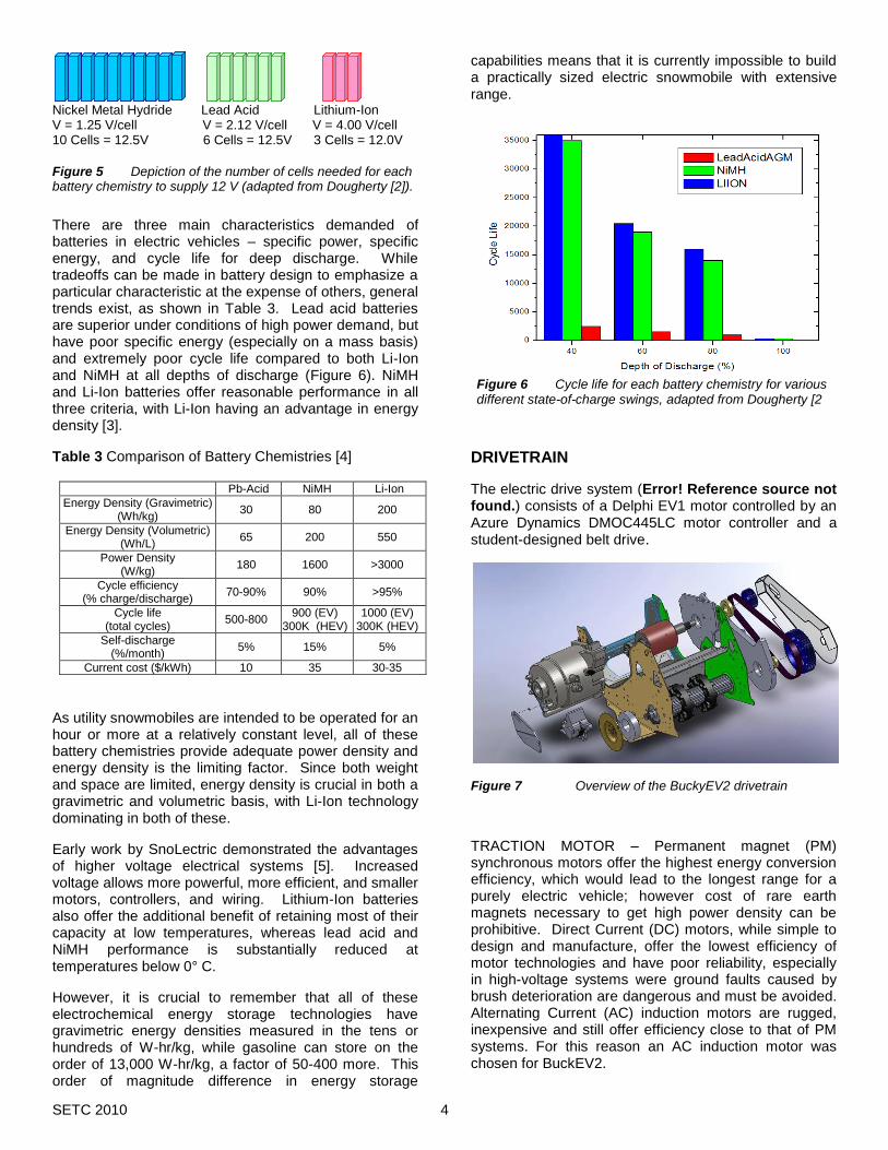
Figure 6 Cycle life for each battery chemistry for various different state-of-charge swings, adapted from Dougherty [2
There are three main characteristics demanded of batteries in electric vehicles – specific power, specific energy, and cycle life for deep discharge. While tradeoffs can be made in battery design to emphasize a particular characteristic at the expense of others, general trends exist, as shown in Table 3. Lead acid batteries are superior under conditions of high power demand, but have poor specific energy (especially on a mass basis) and extremely poor cycle life compared to both Li-Ion and NiMH at all depths of discharge (Figure 6). NiMH and Li-Ion batteries offer reasonable performance in all three criteria, with Li-Ion having an advantage in energy density [3].
Table 3 Comparison of Battery Chemistries [4]
Pb-Acid NiMH Li-Ion
Energy Density (Gravimetric) (Wh/kg)
30 80 200
Energy Density (Volumetric) (Wh/L)
65 200 550
Power Density (W/kg)
180 1600 >3000
Cycle efficiency (% charge/discharge)
70-90% 90% >95%
Cycle life (total cycles)
500-800 900 (EV)
300K (HEV) 1000 (EV)
300K (HEV)
Self-discharge (%/month)
5% 15% 5%
Current cost ($/kWh) 10 35 30-35
As utility snowmobiles are intended to be operated for an hour or more at a relatively constant level, all of these battery chemistries provide adequate power density and energy density is the limiting factor. Since both weight and space are limited, energy density is crucial in both a gravimetric and volumetric basis, with Li-Ion technology dominating in both of these.
Early work by SnoLectric demonstrated the advantages of higher voltage electrical systems [5]. Increased voltage allows more powerful, more efficient, and smaller motors, controllers, and wiring. Lithium-Ion batteries also offer the additional benefit of retaining most of their capacity at low temperatures, whereas lead acid and NiMH performance is substantially reduced at temperatures below 0° C.
However, it is crucial to remember that all of these electrochemical energy storage technologies have gravimetric energy densities measured in the tens or hundreds of W-hr/kg, while gasoline can store on the order of 13,000 W-hr/kg, a factor of 50-400 more. This order of magnitude difference in energy storage
capabilities means that it is currently impossible to build a practically sized electric snowmobile with extensive range.
DRIVETRAIN
The electric drive system (Error! Reference source not found.) consists of a Delphi EV1 motor controlled by an Azure Dynamics DMOC445LC motor controller and a student-designed belt drive.
Figure 7 Overview of the BuckyEV2 drivetrain
TRACTION MOTOR – Permanent magnet (PM) synchronous motors offer the highest energy conversion efficiency, which would lead to the longest range for a purely electric vehicle; however cost of rare earth magnets necessary to get high power density can be prohibitive. Direct Current (DC) motors, while simple to design and manufacture, offer the lowest efficiency of motor technologies and have poor reliability, especially in high-voltage systems were ground faults caused by brush deterioration are dangerous and must be avoided. Alternating Current (AC) induction motors are rugged, inexpensive and still offer efficiency close to that of PM systems. For this reason an AC induction motor was chosen for BuckEV2.
Nickel Metal Hydride Lead Acid Lithium-Ion V = 1.25 V/cell V = 2.12 V/cell V = 4.00 V/cell 10 Cells = 12.5V 6 Cells = 12.5V 3 Cells = 12.0V
Figure 5 Depiction of the number of cells needed for each battery chemistry to supply 12 V (adapted from Dougherty [2]).

SETC 2010 5
The EV1 motor (Figure 8), an AC induction machine developed by Delphi, features a copper bar rotor design that significantly reduces losses and increases power density compared to industrial machines. The motor’s aluminum liquid-cooling jacket allows the motor to produce 100kW peak power and 37 kW of continuous power. This will provide adequate power for cruising while still giving acceleration comparable to mid-range gasoline-powered sleds. The electric motor is transversely mounted in front of the tunnel and is coupled to the track drive paddles via a custom-designed belt drive system.
Figure 9 Plot of optimal operation for a 3.41 gear ratio using the EV 1 motor.
The high torque and wide speed range over which efficient constant power operation is possible allows this
motor to be used in a direct-driven configuration, without a continuously variable transmission (CVT). The motor was geared to operate at 3840 rpm at a vehicle speed of 32 km/hr (20 mph), a rotor speed at which it is slightly less than 90% efficient for torques from 20-40 Nm, as shown in Figure 9. In previous years, Madison’s gear ratio was chosen with a heavy weighting on maximizing efficiency. This resulted in a gear ratio that provided a high top speed, but sacrificed torque. However, because this vehicle is intended to be utilitarian, this year a higher gear reduction was chosen. This results in lower efficiency and top speed, but higher torque which allows for easy towing of extremely heavy loads. Despite the change, the efficiency drop is minimal and the higher energy capacity of the A123 battery allows the snowmobile to maintain the ability of long range operation between charging. A CVT would allow the motor to operate efficiently over a wider range of speeds; CVTs have a peak efficiency of approximately 80%, which would lower the overall system efficiency. Road-load curves for several possible reduction ratios are shown in black, with the red constant-power line indicating the options for 32 km/hr (20 mph) operation.
MOTOR CONTROLLER – An Azure Dynamics DMOC445LC variable speed drive (VSD) motor controller/inverter (Figure 10) has been tuned specifically for operation with the EV1 motor. The DMOC is a liquid-cooled vector drive inverter and is equipped with a Controller Area Network (CAN) bus for vehicle controller interfacing. The inverter is 96-98% efficient, weighs 10.6 kg, and is rated for operation down to -40° C. The unit is rated for a battery input voltage of up to 400 V and can deliver 78 kW (105 hp) peak power and 46 kW (62 hp) continuous power at 312 V. While it does support regenerative braking, there is little energy to be recovered in a utility snow machine due its high drag/inertia ratio losses.
COUPLING – In 2010, the coupling connecting the electric motor to the track drive paddles was analyzed using a component selection matrix. The three types of couplings considered were a belt, chain, and gear drive. The criteria used to determine the best overall coupling were cost, strength, simplicity, and reliability. Simplicity was determined to be the most important criterion, with a weighting factor of 1.5. This criterion was stressed over
Figure 10 Photograph of Azure Dynamics DMOC445LC liquid-cooled 78 kW motor controller (right), alongside the air-cooled unit (left). The liquid-cooled controller offers a higher continuous power rating in a substantially smaller package.
Figure 8 Photograph of the Delphi EV1 copper-bar-rotor AC induction electric motor, with a peak power of 100 kW.

SETC 2010 6
the others because the system must be implemented in a shortened development cycle. Based on the selection matrix, seen in Table 4, a belt drive type was determined to be the best overall selection.
Table 4 Component selection matrix for motor coupling Cost
(x1) Strength
(x1) Simplicity
(x1.5) Reliability
(x1) Factor Sum
Belt 7 8 8 9 8
Chain 7 9 6 8 7.5
Gear 4 10 4 9 6.5
The goals of the CSC necessitate maximizing efficiency during the trail ride, at speeds of approximately 32 km/hr (20 mph). Based on road load predictions as well as motor torque/speed efficiency curves, the optimal gear ratio was just over 3.41:1. With a 75-tooth sprocket on the track drive and a 22-tooth sprocket on the motor, motor speeds of 3840 rpm are seen at 32 km/hr (20 mph), yielding near-peak efficiency without compromising low-speed torque or top speed.
Based on conversations with belt industry representatives at the CSC competition, the team chose to use a prototype belt and sheaves that were developed by Gates Rubber and cooperatively tested by the Wisconsin team (Figure 11). This allows for substantial decrease in weight and eliminates the need for the chain case oil bath (previously the only liquid petrochemical used in the sled) for Wisconsin’s 2011 model.
Figure 11 The belt drive coupling uses a prototype composite belt that was developed in collaboration with Gates Rubber.
The Madison team has proven their direct chain drive system to be practical and efficient with the first two iterations of the BuckEV. However, after conversations with Gates Corp., the team feels that the belt drive system has several key advantages over the previous chain driven model. The two main advantages relate to stretching and vibration. A typical chain drive system can stretch upwards of 3% as a result of the chain/sprocket interface. At the point of 3% elongation, the chain system typically needs to be replaced. However, a similar length carbon synchronous belt drive will only experience about 0.16% elongation over its entire lifetime. Chain drive systems are also subject to increased vibrations. This occurs as a result of each
tooth of the chain being engaged by the sprocket, creating rising and falling pitch line of the chain. The rise and fall effect is transmitted through the entire drive system. On the other hand, carbon synchronous belts run much smoother, due to specially designed curvilinear teeth. This eliminates any speed variation and vibration normally associated with a chain. The advantages of a carbon belt help to improve the performance of bearings and seals and can improve driveline efficiency by up to 5% [13].
Figure12 The displacement of the driven gear under dynamic torsional loading
In order to ensure the belt drive system would be capable of handling the loads delivered by the drivetrain, the gears and structure were tested using SolidWorks Finite Element Analysis (seen in Figures 12 and 13). These models were initially tested under a static axial load of 2010 N (452 lbf) which correlates to 50% more than the maximum stall torque that the EV1 motor could provide. Next, it was dynamically loaded under a pure torsional load of 1423 N-m (1050 ft-lbf), this relates to the maximum load that the gear could see at wide-open throttle (WOT). These two conditions represent the absolute maximum possible circumstances that the belt drive assembly could face in the BuckyEV2 with an additional safety factor of 1.5. Both the stresses and the displacements were analyzed for these two situations. It was determined that both the gears and the mounting structures would pass these desired criterions.
Figure 9 Plot of optimal operation point 3.41 gear ratio using EV1 Motor

SETC 2010 7
Figure 13 The stresses of the driven gear under dynamic torsional loading
Another improvement made to the drivetrain in order to enhance efficiency was to machine the driveshaft paddles to improve their profile. The team purchased a hollow, light weight driveshaft to reduce weight. Like most mass-produced track drives, this one had plastic molded drive paddles. The molding process does not maintain a uniform shape, so the track tension changes as it rotates. This effect of cycling track tension over each revolution reduces efficiency and increases noise and wear. To reduce these effects, the driveshaft was machined on a lathe to ensure drive paddle concentricity.
BATTERY – The BuckEV2 snowmobile uses an energy storage system that consists of 1050 individual A123 Systems ANR26650M1A cells arranged in 10 parallel and 105 in series. To minimize/correct imbalances in cells, the batteries are connected to a common connector as shown in Figure 14 between each increase in voltage potential. These cells are normally packaged into Dewalt cordless battery packs and are mass produced on an assembly line with stringent quality control. The cells are rated for over 1000 cycles at a 100% depth-of-discharge.
The A123 Systems ANR26650M1A cells were chosen due to their high peak power, high energy density, and capability for continuous discharge at high rates without risk of overheating or damage. The A123 cells have a 15% higher energy density than the Milwaukee Tool cells that were previously utilized.
The pack was assembled by High Tech Systems LLC with custom copper interconnects which also function as fuses for parallel cells. The pack is configured into one self-contained battery box that sits on top of the tunnel where the seat is normally located. A custom seat was designed to cover the battery enclosure while providing a comfortable ride. The pack has a rated capacity of 23 A-hr at a nominal voltage of 347 V, capable of continuous discharge at 1250 A (exceeding the 280 A capacity of the electric drive). The 7.97 kW-hr battery
pack will provide a utility range from 20 to 25 miles depending upon trial conditions.
In order to maximize safety for both the rider and the electrical system, the copper interconnects between the cells were designed to act as fuses in the event that a cell short circuits. Initial testing utilized a TIG welder as a constant current power supply to melt various widths of 0.005 in thick copper foil. Tests were conducted at 100 A, 150 A, and 200 A. Given a worst case scenario where a cell has internally short circuited the 9.2 mm wide fuse is designed to blow in no more than 8 seconds with a 150 A applied. Figure 14 shows the fuse characteristics of the 0.005 in thick copper foil used in the construction of the BuckEV2 battery.
Figure 14 Graph displaying fuse width vs. burn through time of 0.005 in thick copper.
Figure 15 Picture showing the common conductor fuse used to connect the individual cells.
BATTERY MANAGEMENT- Battery management systems (BMS) are essential to safe and reliable use of lithium-ion battery packs. Li-Ion cells naturally self-discharge at varying rates. A pack consisting of many cells in series will gradually become unbalanced, with

SETC 2010 8
some cells at a higher state of charge than others. Since these cells cannot tolerate overcharging, it is not possible to equalize the pack by slowly overcharging it, as can be done for other battery chemistries. The BuckEV2 contains a distributed BMS which consists of monitoring and equalization modules mounted on each series unit, all communicating with a central control module.
This system monitors per-cell temperature and voltage in addition to automatically equalizing the pack during charging by switching the highest-charged cells across integrated discharge resistors. The BMS interacts with the main vehicle control computer, providing an indication of the battery state of charge. By knowing state-of-charge, it is possible to avoid over-charging or over-discharging the battery pack, conditions that reduce longevity and can be unsafe. High Tech Systems LLC is providing the individual monitoring boards which transmit information to the BuckEV2 control which calculates battery state of charge.
High Tech Systems, LLC
Figure 16 Picture of the individual battery monitoring boards installed on a battery pack [14].
The cells maintain full performance down to temperatures of 10° C and have been tested by the manufacturer down to –20° C. Reduced power delivery performance is seen when cold, but very cold cells will heat up due to increased internal resistance, and 90% of normal power is available within 105 s of start-up (at 20 A per string discharge).
Safety, weight balance, center-of-gravity height, and serviceability were foremost concerns in the design of the battery pack. The battery pack is contained in a polycarbonate shell and has no exposed conductive surfaces. Inside the pack, non conductive sheets of phenolic are used to isolate open conductors and the battery is assembled so as to minimize the voltage potential between adjacent cells. The battery pack can be trivially disconnected from the drive (isolating them
electrically) or even removed entirely to permit vehicle service without high-voltage electrical hazards or to comply with shipping regulations.
Table 5 Battery Pack Specification
Characteristic 2011 BuckEV2
Battery Mass (w/packaging)
78 kg (172 lb)
Nominal Voltage 347 V
Capacity 23 A-hr
Energy 7970 W-hr
Power Density 4337 W/kg
Energy Density 108.4 W-hr/kg
High Tech Systems, LLC
Figure 17 Picture of a fully assembled battery pack just before the cover is installed [14].
BATTERY HEATING SYSTEM – When Li-ion cells are placed in extremely cold environments, such as those encountered at Summit Station, Greenland, the lithium inside the cells can freeze. When this occurs the electrons cannot flow well through the cells. If the battery is charged in this condition the cells become drastically unevenly charged, causing one side to be over charged. This overcharging causes deterioration of cell life cycle and ability to hold charge.
In large battery packs, such as the one in the BuckEV2, the internal resistance of the cells during charging can raise the temperature of the pack. However, the frigid environment will keep the cells on the periphery of the pack cold. This variance of temperature within the pack can cause even more damage during charging because,

SETC 2010 9
the cells at the core of the pack will be fully charged while the charger pushes extra current through them. This results in damage to the entire cell, for cells at the center of the pack and partial damage to the cells on periphery of the pack.
In order to lessen the effects of the harsh environment during charging, the team integrated a heating system into the battery. The heating system consists of layers of Warmzone “FloorHeat” sandwiched between the battery layers. FloorHeat is a Positive Temperature Coefficient semi-conductive polymer that increases in temperature when current is passed through it. FloorHeat is ideal for this application because it is self regulating; as it heats up the current that passes through it lessens and the heat out put decreases. The total power output for the FloorHeat in the BuckEV2 battery has a maximum power output of 224.4 W.
FIGURE 18 Picture of a sheet of FloorHeat
AUXILIARY ELECTRICAL SYSTEM – A conventional 12V electrical system is required to operate the lights, hand warmers, coolant pump, and vehicle controllers. A 12 V 5 A-hr sealed lead-acid battery (1.69 kg) buffers power demands and a Solectria 750 W DC/DC converter (3.00 kg) supplies 12V power from the high voltage pack. This power converter offers ≥95% efficiency and uses nearly zero power when not in operation.
To reduce parasitic electrical losses, all incandescent miniature light bulbs have been replaced with high-efficiency Light-Emitting Diodes (LEDs), saving 30 W of continuous power (0.5% range improvement per hour of operation) and improving reliability (there is no filament to burn out). During daytime operating conditions, the LED running lights are used, saving an additional 100 W (1.5% additional range improvement per hour of operation). Together these modifications improve range by approximately 0.6 km (0.4 mi) at 32 km/hr. For operator comfort, the conventional passive electrical hand-warmers were retained – their operation requires up to additional 65 W, reducing range by approximately 1%.
Because the 12V system is supplied by the large high-voltage battery, the vehicle can service as a source of power for external devices. The headlights can be operated for more than three days as an auxiliary light source, and a plug is available to plug in a 120VAC inverter, allowing up to 750W continuous power (for over ten hours) and 1500 W of peak power, enough to run many AC power tools. This may eliminate the need for a gas-powered generator in some remote applications.
COOLING SYSTEM – The motor and controller have a closed-loop liquid cooling system with a 60/40 mixture of ethylene-glycol and distilled water which supplies freeze protection down to -56° C (-69° F). The coolant is circulated using a Bosch electric water pump. The pump flows up to 15 L/min and requires 18 W. It is typically run at a reduced rate according to system temperature and power output. As the electric drive is liquid-cooled, the entire hood is sealed, preventing the intrusion of water, snow or dirt, to improve reliability and ease of servicing. Experience from the previous design showed that the cooling system is more than adequate. To date,
the highest logged coolant temperature has been 25 C – well below the electronics peak operating temperature of
80 C.
The batteries have extremely low internal resistance, leading to very low levels of heating. The battery supplier has advised the team that the batteries can be continuously discharged at 70 A without overheating. Thermal analysis of the pack shows that, based on a
measured cell resistance of 10 m and an estimated
battery heat capacity of 800 J/kg/ C [9], a peak temperature rate of increase of 13 K/min will be seen at a maximum continuous discharge rate of 280 A. As this rate of discharge will completely exhausted the pack in approximately 4 minutes, a peak temperature rise of 55 K will be seen. Since the batteries are rated for a
maximum operating temperature of 70 C, vehicle operation is typically expected at temperatures below
10 C, and some heat will be lost to the surroundings, it is not anticipated that battery cooling will be required during vehicle operation or charging. However, thermistors were installed to sense battery temperature, allowing the controller to derate power if necessary for battery protection. During a ten-day period of study in Greenland, observed battery temperatures ranged
between -20 C and +17 C.
CHARGING SYSTEM – The sled is typically charged using an on-board Brusa NLG513 3.3 kW charger. The charger operates between 120-240 VAC and is capable of providing output currents up to 12.5 A. The charger is controlled via CAN by the main vehicle controller – when the vehicle is plugged in, the system powers up automatically, detects the state-of-charge, and initiates charging if necessary, following an algorithm recommended by the battery manufacturer.
The batteries are charged at a current of up to 2.5 A/string until the cells reach 3.3 V (347 V overall). Constant-voltage charging then continues at 3.3 V/cell

SETC 2010 10
until current drops to 50 mA per string. This leads to a full charge in approximately 120 minutes. The batteries are capable of rapid charging using a 6kW charger at up to 40 A/string, allowing a full charge in approximately 20 minutes, but this would require a 240V/100A power connection, which is not commonly available, and may reduce battery life.
VEHICLE CONTROL SYSTEM
CONTROL HARDWARE - The BuckEV2 uses a Woodward/MotoTron ECM-0555-080-0312M Powertrain Control Module (PCM) embedded controller specifically designed for automotive applications. The PCM is hermetically sealed and suitable for rugged environments, with operational ratings that allow temperatures from -40˚C to 130˚C, high acceleration and vibration (direct engine mounting in marine racing applications is permitted), and indefinite submersion in 3 m of water. It has 15 analog inputs, 6 digital inputs, 20 low side driver (LSD) power outputs capable of pulse width modulation (PWM) control, a technique for variable power output), 8 logic level outputs and dual CAN 2.0B interfaces.
Figure 19 Picture of the ECM-0555 powertrain control module
Vehicle controller inputs include accelerator position sensor, brake switch, stop switch, reverse switch, cruise control switches, auxiliary system voltage and battery temperature and current sensors. Feedback from the Azure Motor Controller over the CAN link yields battery voltage, vehicle (motor) speed, motor and controller temperature, actual torque and current, and any drivetrain faults. The vehicle controller transmits a torque command and optionally a target speed (for cruise control) to the Azure motor controller over the CAN link. It also controls the speedometer, the variable-speed coolant pump and all displays and warning lights .
CONTROL SOFTWARE – The control strategy was developed using the MotoHawk development system, which allows for rapid control prototyping using MATLAB Simulink. The Simulink block diagram is automatically converted into C code and compiled directly to run on
the embedded target platform, simplifying control system implementation.
VEHICLE SAFETY AND SELF-DIAGNOSTIC CAPABILTIES – The control system has a sophisticated fault detection mechanism to ensure safety and diagnose vehicle malfunction. Every input is continuously range-checked to detect failed or disconnected sensors. Continuous CAN communications between the vehicle and motor controller is necessary for operation of the electric drive (shutdown automatically occurs within 50 ms of a loss of communication), and a multitude of temperature sensors ensuring that temperature thresholds are not exceeded. Faults are signaled to the operator using flash codes on the “Check Engine” dashboard indicator, and a human-readable text description of the fault scrolls on the MiniView gauge. For troubleshooting, all sensor values and internal control strategy variables can also be examined at any time on the MiniView. The snowmobile’s dashboard temperature indicator warns the driver if performance is being reduced due to low or high temperatures.
For electrical safety, the high voltage bus is entirely isolated from the chassis and the auxiliary electrical system. This isolation is continuously monitored using a Bender RCM475LY Ground Fault Monitor. If an unintentional connection between the DC or AC high-voltage busses and the chassis permitting leakage current in excess of 10 mA is detected, an audible alarm is sounded, the electric drive is shut off, and all vehicle lights are flashed continuously to warn the operator. This improves safety by warning of hazards caused by improper servicing or physical damage to the battery. The conventional stop switch and tether disable all outputs from the controller and physically interrupt the power to the main high-voltage contactors, disabling the electric drive.
The vehicle has an on-board data acquisition system which logs every aspect of its operation once per second. Recorded fields include time, position (via GPS), speed, user inputs, commanded and actual torque, battery voltage and per-string current, estimated battery stage of charge, battery, motor, and inverter temperature, cruise control state, and charging system state. In Greenland, these logs were downloaded by Summit Camp staff every two weeks. This data has aided the team in refining its snowmobile control strategy.
CHASSIS AND HANDLING
The BuckEV2 is based on a 2010 Polaris IQ Shift chassis (Figure 20). The chassis allows for easy access to the entire engine bay through the hood and two removable side panels. The side panels open up to two large bays well suited for mounting electrical components. This chassis also utilizes an innovative seat mounting system which makes the seat easy to remove and modify, enabling it to be easily installed.

SETC 2010 11
With the full weight of the battery pack mounted over the rear suspension and the weight of the electric motor and other electrical components in front the shocks needed to be very rigid and durable.
The IQ chassis is equipped with Polaris’s top of the line suspension package. The rear shocks are produced by Fox and give the sled a rear travel of 35.3 cm (13.9 in). The main rear shock is the fully adjustable model to allow for desired tuning of the ride. The front shocks are Walker Evans compression- adjustable models and give the machine a front travel of 25.4 cm (10 in). This package gives the Shift a fully tunable suspension which greatly increases the handling capabilities and allows for the team to properly calibrate the suspension for the additional weight being placed in the rear of the chassis.
For rider protection and to prevent slipping, the chassis has wide running boards with an integrated traction surface.
NOISE REDUCTION
Noise reduction was prioritized below range and performance, as research-related snowmobile operations tend to be take place in isolated locations (without neighbors), be low in volume (minimizing impact on wildlife), and are conducted by researchers who tend to be interested solely in utility and little concerned with other factors. Furthermore, noise from electrical sleds is very minimal.
Sound testing of the BuckEV2 prior to the 2011 competition showed noise levels at 58-60 dB at 48 km/hr (30 mph) and 54-57 dB at 24 km/hr (15 mph), based on the peak of the A-weighted fast response measurements during a pass-by at 15.2 m (50 ft) on each side. These levels correspond to normal spoken conversation and are not disruptive to bystanders. Sound level measured at the ear of the occupant was 76 dB, quieter than the standard for an IC-powered snowmobile measured at 15.2 m (50 ft), and well below the OSHA standard for an eight-hour workday.
With the electrical drivetrain, mechanical noise from the belt-drive and track is more evident and steps were taken to reduce sound emission from the BuckEV2.
Spectral sound analysis had previously been conducted on an IC-engine powered snowmobile to determine the major sources of sound emission. The sources of the three major peaks were determined by calculating the first and second order contributions of several snowmobile components at 72 km/hr (45 mi). Major noise peaks are the track/paddle interface at 300 Hz and 600 Hz and the chain case at 1350 Hz and 2700 Hz. Consequently, mechanical noise reduction on the BuckEV2 has been focused on the chain-case and drive paddles. The belt drive has been encased in a custom aluminum housing. This housing has been powder-coated, lined with nylon belting and reinforced with stiffeners to dampen sound.
Due to the competition scoring’s major emphasis on noise, a drive paddle noise dampener, invented and developed by team members in 2004, was installed on the front arm of the rear suspension. This dampener contains and attenuates the sound produced by the drive paddles contacting the drive lugs on the track. Previous testing shows that this dampener entirely eliminates the drive paddle sound power at 300 Hz and its harmonics. At the 2010 CSC, the BuckEV2 had measured noise levels of 64 dB according to the competition test procedure, the second best of all entrants.
RANGE
ROAD LOAD ANALYSIS – The battery was initially designed in 2008 based on the road-load model by Auth [8], which predicted power demands of 4.6 kW (6.2 hp) at 32 km/hr (20 mph). With the battery at a mean voltage of 320 V, this corresponded to a current of 14 A, so the 19.6 A-hr pack used in 2008 should have lasted 1.4 hours and allowed a range of 45 km (28 mi). This road-load figure of 230 W-hr/mi and the resulting range were believed to be optimistic, as initial testing showed a current consumption of 20 A at 32 km/hr (20 mph), suggesting a road load of 340 W-hr/mi, so a battery pack with ~20 A-hr capacity would travel 32 km (20 mi) at 32 km/hr (20 mph).
Road-load testing was performed with a partial battery pack as soon as the 2008 vehicle could be made operational. The vehicle was tested at a weight approximately 45 kg (100 lbs) below its final weight as well as in a ballasted configuration that approximates its finished weight with a 90 kg (200 lb) rider. Battery current was recorded (including auxiliary loads) at speeds in 8 km/hr (5 mph) increments from 8 km/hr (5 mph) to 56 km/hr (35 mph). The useful pack capacity was estimated to be 19.0 A-hr, corresponding to the maximum 97% depth-of-discharge recommended by the manufacturer. Typical per-string currents were below 6 A at these speeds, low enough that high-current capacity derating is unnecessary and nearly full capacity should be available.
Figure 20 The IQ Shift chassis provides excellent handling for all types of rider over a variety of terrain.

SETC 2010 12
This analysis, shown in Figure 22 predicted that efficiency is highest at relatively low speeds, below 25 km/hr (15 mph). The predictions at very low speed (8 km/hr, 5 mph) are considered to be unreliable due to difficulty in maintaining precise speed control and large fluctuations in load and non-linear track behavior at very low track speeds. For 2011, considering the increased pack capacity and improved system efficiency, the authors predicted a range of 40 km (24.3 mi) on hard packed snow.
TESTING – Prior to the 2008 competition, a full range test with the full battery was performed on the finished 2008 vehicle. The vehicle traveled 22.0 km (13.7 mi, measured by odometer calibrated against GPS) on an 1.0 km (0.6 mi) oval course at a target speed of 32 km/hr (20 mph) before reaching the predetermined stopping criteria of 15% estimated remaining battery capacity. If the test had been continued to the 97% depth-of-discharge, the expected distance would have been 25.2 km (15.6 mi). Snow conditions for the test were 20 cm (8 in) of snow, consisting of 15 cm (6 in) of loose unconsolidated powder atop 5 cm (2 in) of densely packed snow. The sled had to “break trail” (establish a packed path through soft snow) during the first lap, requiring a measured power consumption of 10 kW (500 W-hr/mi), but then followed in its packed tracks, for a lower power consumption of 6 kW (300 W-hr/mi), increasing gradually to 7 kW (350 W-hr/mi). The increased power consumption towards the end is attributed to the sled sinking deeper into the snow, to the point that the front suspension was dragging in loose snow. As expected, a groomed, hard-packed trail produces maximum range results.
Road Load Plot: Power vs. Speed
Figure 22 This road load plot shows power vs. speed (for both steady state conditions and during acceleration) for the entire summer 2008 season in Greenland.
Testing in Greenland showed that towing a trailer sled leads to enormous increases in road load and thus substantially decreases in range. The minimum road load observed in Greenland, assumed to be the sled with a single operator and no towed payload, was 360 W-hr/mi, with laden values averaging 600 W-hr/mi and maximum values of approximately 800 W-hr/mi. Thus, the loaded range is a factor of 2-3 lower than the range measured in the competition range event, suggesting that a minimum unloaded range of 20-30 miles is necessary to reliably achieve a ten mile useful range (Figure 21-22).
Figure 23 Plots of power and current against speed during periods of steady-state operation at Summit camp. At ambient
temperatures of approximately –15 C (+5 F),two distinct trial load curves emerged: single riders (lower line) and pulling a sled (upper line).
Figure 21 Predicted range for the 2008 design at various speeds for a 97% depth-of-discharge. Initial testing was performed with a reduced battery pack and the vehicle was ballasted to simulate its final weight. The 20 mi range prediction is based on current measurements from the 2008 CSC Range event, and the 10 mi range prediction is based on towing a loaded sled in Greenland.

SETC 2010 13
Tractive Effort: Pull force vs. Speed
Figure 24 Tractive effort is plotted against speed for every logged point during the summer in Greenland. Data points where acceleration is zero are plotted in red, while points of acceleration or slowing are plotted in blue. This shows that approximately 130 lbf (578 N)of steady-state tractive force are required to move the sled and rider (independently of speed, between 5-15 mph), with towed sleds causing an additional 100-150lbf (445 - 667N) of drag.
DRIVELINE EFFICIENCY TESTING
Taking advantage of the direct drive of the BuckEV, the team was able to conduct driveline efficiency testing. This was done by data logging motor torque and shaft speed during testing which allowed for very precise measurement of road load at each driveline configuration.
In consideration of the competition’s focus on the draw bar pull event, the team considered switching from the standard 121 inch track and suspension to a 128 inch model. This would increase the contact area at the track to ground interface and also allow for additional traction devices (studs) to be installed. To determine the effects of this change the team conducted an extensive range of testing on the driveline efficiency associated with this machine. While the testing focused on track length, additional consideration was given to the effects of studs, track weight, and bogey wheel position.
Since the range event is run at an average speed of 32 km/hr (20 mph) that data point was specifically identified in the comparison. The 121 inch model required an average of 8.9 kW of power to travel at a speed of 32 km/hr (25 mph). In comparison, the 128 inch model required 11.4 kW of power to travel at the same speed. This would relate to a 22% increase in power required to drive the machine, while at most increasing the draw bar pull results by 5% (due to the limit of the drivetrain). The team concluded that it would be most beneficial to keep the stock suspension and try to improve the draw bar pull in another way.
Figure 25 The battery power drawn for a range of speeds from 10 mph to 30 mph. Both tests were run on the same night in nearly identical conditions
Additional testing was done to determine if additional range could be obtained by reducing road load via optimal driveline efficiency. These tests included determining the effects of studs, track weight and bogie wheel placement.
ROAD LOAD PLOT: POWER VS. SPEED
The first test that was run was a simple comparison of having studs installed vs. a non-studded track. Based on the results (Figure 26) the power required with the non-studded track to travel at 32 km/hr (20 mph) was 9.8 kW, this value is slightly less than the 10.2 kW required with a studded track. This difference correlates to an approximate 4 % increase in load to have studs on the machine. This data was combined with previous competition draw bar pull results when deciding to install studs on the sled for competition.
Road Load Plot: Power vs. Track Speed
Figure 26 The battery power drawn for a range of speeds from 10 mph to 30 mph. Tests were run on packed ice/snow conditions
5 10 15 20 25 304
6
8
10
12
14
16
18
Track Speed [mph]
Po
we
r [
kW
]
121" - Ice121" - Ice
128" - Ice128" - Ice
Road Load Plot: Power vs. Speed
SETC 2010 14
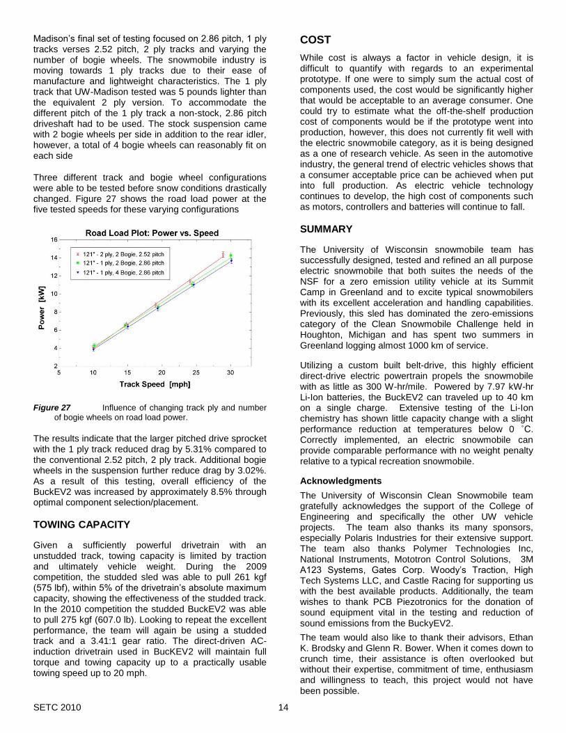
Madison’s final set of testing focused on 2.86 pitch, 1 ply tracks verses 2.52 pitch, 2 ply tracks and varying the number of bogie wheels. The snowmobile industry is moving towards 1 ply tracks due to their ease of manufacture and lightweight characteristics. The 1 ply track that UW-Madison tested was 5 pounds lighter than the equivalent 2 ply version. To accommodate the different pitch of the 1 ply track a non-stock, 2.86 pitch driveshaft had to be used. The stock suspension came with 2 bogie wheels per side in addition to the rear idler, however, a total of 4 bogie wheels can reasonably fit on each side
Three different track and bogie wheel configurations were able to be tested before snow conditions drastically changed. Figure 27 shows the road load power at the five tested speeds for these varying configurations
Figure 27 Influence of changing track ply and number of bogie wheels on road load power.
The results indicate that the larger pitched drive sprocket with the 1 ply track reduced drag by 5.31% compared to the conventional 2.52 pitch, 2 ply track. Additional bogie wheels in the suspension further reduce drag by 3.02%. As a result of this testing, overall efficiency of the BuckEV2 was increased by approximately 8.5% through optimal component selection/placement.
TOWING CAPACITY
Given a sufficiently powerful drivetrain with an unstudded track, towing capacity is limited by traction and ultimately vehicle weight. During the 2009 competition, the studded sled was able to pull 261 kgf (575 lbf), within 5% of the drivetrain’s absolute maximum capacity, showing the effectiveness of the studded track. In the 2010 competition the studded BuckEV2 was able to pull 275 kgf (607.0 lb). Looking to repeat the excellent performance, the team will again be using a studded track and a 3.41:1 gear ratio. The direct-driven AC-induction drivetrain used in BucKEV2 will maintain full torque and towing capacity up to a practically usable towing speed up to 20 mph.
COST
While cost is always a factor in vehicle design, it is difficult to quantify with regards to an experimental prototype. If one were to simply sum the actual cost of components used, the cost would be significantly higher that would be acceptable to an average consumer. One could try to estimate what the off-the-shelf production cost of components would be if the prototype went into production, however, this does not currently fit well with the electric snowmobile category, as it is being designed as a one of research vehicle. As seen in the automotive industry, the general trend of electric vehicles shows that a consumer acceptable price can be achieved when put into full production. As electric vehicle technology continues to develop, the high cost of components such as motors, controllers and batteries will continue to fall.
SUMMARY
The University of Wisconsin snowmobile team has successfully designed, tested and refined an all purpose electric snowmobile that both suites the needs of the NSF for a zero emission utility vehicle at its Summit Camp in Greenland and to excite typical snowmobilers with its excellent acceleration and handling capabilities. Previously, this sled has dominated the zero-emissions category of the Clean Snowmobile Challenge held in Houghton, Michigan and has spent two summers in Greenland logging almost 1000 km of service.
Utilizing a custom built belt-drive, this highly efficient direct-drive electric powertrain propels the snowmobile with as little as 300 W-hr/mile. Powered by 7.97 kW-hr Li-Ion batteries, the BuckEV2 can traveled up to 40 km on a single charge. Extensive testing of the Li-Ion chemistry has shown little capacity change with a slight performance reduction at temperatures below 0 ˚C. Correctly implemented, an electric snowmobile can provide comparable performance with no weight penalty relative to a typical recreation snowmobile.
Acknowledgments
The University of Wisconsin Clean Snowmobile team gratefully acknowledges the support of the College of Engineering and specifically the other UW vehicle projects. The team also thanks its many sponsors, especially Polaris Industries for their extensive support. The team also thanks Polymer Technologies Inc, National Instruments, Mototron Control Solutions, 3M A123 Systems, Gates Corp. Woody’s Traction, High Tech Systems LLC, and Castle Racing for supporting us with the best available products. Additionally, the team wishes to thank PCB Piezotronics for the donation of sound equipment vital in the testing and reduction of sound emissions from the BuckyEV2.
The team would also like to thank their advisors, Ethan K. Brodsky and Glenn R. Bower. When it comes down to crunch time, their assistance is often overlooked but without their expertise, commitment of time, enthusiasm and willingness to teach, this project would not have been possible.

SETC 2010 15
REFERENCES
1 Veco Polar Services, “Greenland Summit Camp Site Plan 2005 (1:200 scale)”.
2 Dougherty T, “Johnson Controls Inc on Battery Technology”, Presentation at the SAE Milwaukee Section meeting, Feb 2004.
3 Köhler, Kümpers, Ullrich, “High Performance Nickel-Metal Hydride and Lithium-Ion Batteries”, J. Power Sources 105(2):139-144, 2002.
4 Alamgir, M, Sastry, AM, “Efficient Batteries for Transportation Applications” 2008, SAE 2008-21-0017.
5 Hansen G, “Electric Snowmobile Demonstration Status Report: SnoLectric”, August 2001.
6 Bower G, et al., “Design of a Charge Regulating, Parallel Hybrid Electric FutureCar,” 1998, SAE 980488.
7 Bayer J, Koplin M, et al., “Optimizing the University of Wisconsin’s Parallel Hybrid-Electric Aluminum Intensive Vehicle,” 1999, SAE 1999-01-0613.
8 Auth, “Determining Hybrid Electric Snowmobile Feasability Through Simulation”, M.S. Thesis, 2003.
9 Pesaran, Keyser, “Thermal Characterization of Selected EV and HEV Batteries”, presented at the Annual Battery Conference (Long Beach, CA), 2001.
10 Wiegman H, Vandenput A., "Battery State Control Techniques for Charge Sustaining Applications," SAE Publ. 981129, SP-1331, 1998, pp 65-75 , and 1999 SAE Transactions.
11 Helgren, JM, et al., “Design and Development of the University of Wisconsin’s Parallel Hybrid Electric Sport Utility Vehicle” SAE Publications March, 2003, SAE 2003-01-1259.
12 Hermance RS, “Analysis of the Effectiveness of Snowmobile Traction Products in Enhancement of Snowmobile Safety”. Snowmobile Educational Safety Research Association, 1997.