zmx stepper motor power stage with servicebus
TRANSCRIPT
Manual 2111-A012 EN
+ZMX
Stepper Motor Power Stagewith ServiceBus
ID 10016809

phytron
3 MA 2111-A012 GB
Contents 1 ZMX+ ........................................................ 4
1.1 Overview ............................................. 4
1.2 Operating Mode ................................... 7
1.2.1 Rotary Switch Mode ...................... 7
1.2.2 ServiceBus Mode ......................... 7
1.3 Directives and Standards ..................... 8
1.4 Declaration of Incorporation ................. 9
2 To Consider Before Installation ................ 10
2.1 Qualified Personnel ............................ 10
2.2 Safety Instructions .............................. 10
2.3 Ambient Conditions ............................ 12
3 Protective Measure Options ..................... 13
4 Design Requirements ............................... 15
4.1 Electromagnetic Compatibility (EMC) . 15
4.1.1 Remarks ...................................... 15
4.1.2 EMC Measures ............................ 16
4.2 Shielding ............................................ 18
4.3 Insulation Overview ............................ 19
4.4 Cables ................................................ 20
4.5 Calculation of the Supply Unit ............. 21
4.6 Mains Supply Unit ............................... 22
5 Technical Data ......................................... 23
5.1 Mechanical Data ................................. 23
5.2 Electrical Data .................................... 24
6 Installation ................................................ 27
6.1 Mechanical Installation ....................... 27
6.2 Electrical Installation ........................... 28
6.2.1 Motor connection ......................... 28
6.2.2 Wiring Schemes .......................... 30
6.3 Connector ........................................... 31
6.3.1 ServiceBus Connector ................. 31
6.3.2 Connectors .................................. 31
7 Putting into Service ................................... 33
7.1 LED Display ........................................ 33
7.2 Rotary Switches .................................. 34
7.3 DIP Switches ...................................... 34
7.4 DIP Switch Setting .............................. 35
7.5 Rotary Switch Mode ............................ 36
7.6 ServiceBus Mode ................................ 37
7.7 Checking the Installation ..................... 39
8 Functions .................................................. 40
8.1 Inputs .................................................. 40
8.1.1 CONTROL PULSES .................... 42
8.1.2 BOOST ........................................ 43
8.1.3 DEACTIVATION ........................... 43
8.1.4 RESET ......................................... 44
8.1.5 DIRECTION ................................. 45
8.1.6 STEP RESOLUTION ................... 46
8.2 Outputs ............................................... 47
8.2.1 BASIC POSITION ........................ 47
8.2.2 ERROR ........................................ 48
9 ESD Protective Measures ......................... 49
10 Warranty and Trade Marks ....................... 50
10.1 Warranty ........................................ 50
10.2 Trade Marks ................................... 50
11 Technical Glossary ................................... 51
11.1 Boost ............................................. 51
11.2 Current Delay Time ........................ 52
11.3 Overdrive ....................................... 53
12 Index ......................................................... 54

Manual ZMX+
MA 2111-A012 EN 4
1 ZMX+
1.1 Overview
Fig. 1: Control components
Microstep Power Stage for Two-Phase Stepper Motors
The power stages type ZMX+ are used for bipolar control of two-phase stepper motors with phytron´s well-tried technology, now with enhanced 4 quadrant chopper type current control. The automatic phase current optimization ensures an accurate phase current regulation, even lower than 600 mA.
The operating parameters – run current, step resolution and preferential direction – can be set either by rotary switches (rotary switch mode) or by ServiceBus (ServiceBus mode).
The + of the power stage ZMX+ stands for “operation with ServiceBus” by ServiceBus-Comm for Windows®. The configuration software is included in delivery for easy use of all setting options.
The ServiceBus enables configuration, programming and diagnostic via PC.

phytron
5 MA 2111-A012 EN
ZMX+ versions
Electrical isolation with without
Pin connector 48 pin (F) 32 pin (D) 48 pin (F) 32 pin (D)
ServiceBus RS 485 RS 485 without RS 485 RS 485 without
Ident No. 10016066 10016100 10015025 10016102 10015958 10015172
Operating mode
SBM or RSM only RSM SBM or RSM only RSM
SBM= ServiceBus mode RSM= Rotary switch mode
Electrical isolation
The inputs and outputs are optically isolated from the ZMX+ power supply.
VG Pin connector DIN 41612
32 pin (D): Pin compatible with standard power stages on the market, ServiceBus connector at the front side.
48 pin (F): Additional ServiceBus connection at the SLS-ZMX+ power stage unit backplane.
ServiceBus mode
The ServiceBus offers the following possibilities:
• Power stage parameter programming: Run, stop and boost current, step resolution, preferential direction, current delay time, etc.
• Configuration by software via 4 wire or 2 wire RS 485 bus or CAN.
• Parameter memory to hold data safely in the power stage EPROM.
• Activate or deactivate the function Overdrive
The instruction set for power stage parameterization is listed in the ServiceBus manual.
The power stage can easily and quickly be programmed by ServiceBus-Comm® software. (See ServiceBus-Comm® manual )

Manual ZMX+
MA 2111-A012 EN 6
Rotary switch mode
The operating parameters – e. g. run current, step resolution, preferential direction – can be set by the rotary switches.
Inputs
The logic of the inputs CONTROL PULSES, DIRECTION, BOOST, DEACTIVATION and RESET can be defined by the DIP switch on the board or by the ServiceBus.
Outputs
Both outputs of the ZMX+, BASIC POSITION and ERROR, are open collector outputs.
Easy to mount and EMC-compatible design
The ZMX+ power stage is designed for mounting in 19”/3U racks. All wiring is connected to a 32 pin connector (type D) or a 48 pin connector (type F) according to DIN 41612 depending on the version.
Extent of supply
• ZMX+ manual
Included in delivery:
• ZMX+ with ServiceBus: ServiceBus-Comm manual ServiceBus manual Phytron CD with the ServiceBus-Comm software
Supplementary parts are available:
• Front panel with handle (#10010085)
• ServiceBus cable
• CAN bus terminating plug
• USB-RS 485 converter as stick (#10012295)

phytron
7 MA 2111-A012 EN
1.2 Operating Mode
The ZMX+ can be served by 2 operating modes:
1.2.1 Rotary Switch Mode
All operating mode parameters are set by the DIP and rotary switches at the front side or on the board.
1.2.2 ServiceBus Mode
The SB active DIP switch activates the ServiceBus mode when “ON” and all operating parameters can only be set by ServiceBus.
RS bus: The parameters for the ZMX+ operation are set via RS 485 4 wire mode (full duplex).
CAN bus: The ZMX+ parameterization is set by a Controller Area Network (CAN) in the 2 wire mode. Up to 16 power stages can be connected to one CAN bus.
All settings are made on a PC by phytron´s ServiceBus-Comm® software.
The Address rotary switch address of the device.
Important: Each address must only be used once!

Manual ZMX+
MA 2111-A012 EN 8
1.3 Directives and Standards
CE Mark With the declaration of conformity and the CE Mark on the product the manufacturer certifies that the product complies with the requirements of the relevant EC directives. The unit, described here, can be used anywhere in the world.
EC Machine Directive The drive system, described here, isn´t a machine in the sense of the EC machine directive (2006/42/EC), but a component of a machine for installation. They have no functional moving parts. But they can be part of a machine or equipment. The conformity of the complete system in accordance with the machine guideline is to be certified by the manufacturer with the CE marking.
EC EMC Directive The EC Directives on electromagnetic compatibility (89/336/EEC) applies to products, which can cause electromagnetic interference or whose operation can be impaired by such interference. The power stage’s compliance with the EMC Directive cannot be assessed until it has been installed into a machine or installation. The instructions provided in “Installation” must be complied with to guarantee that the ZMX+ is EMC compliant when fitted in the machine or installation and before use of the device is permitted.
Standards for safe operation
EN 60204-1: 1998-11: Electrical equipment of machines, degree of pollution 2 must be observed
EN 60529: IP Degree of protection
Standards for observing the EMC limit values
EN 61000-3-2: EMC
EN 61000-6-1,3,4: Emission standard
EN 61000-6-2:2005: EMC Immunity for industrial environments
Standards for measuring methods of observing EMC limit values
EN 55011 class B: Noise field and voltage measuring
EN 61000-4-2...6,11 Emission standard test

phytron
9 MA 2111-A012 EN
1.4 Declaration of Incorporation
Manual ZMX+
MA 2111-A012 EN 10
2 To Consider Before Installation
Read this manual very carefully before installing and operating the ZMX+. Observe the safety instructions in the following chapter!
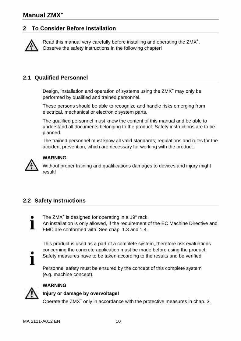
2.1 Qualified Personnel
Design, installation and operation of systems using the ZMX+ may only be performed by qualified and trained personnel.
These persons should be able to recognize and handle risks emerging from electrical, mechanical or electronic system parts.
The qualified personnel must know the content of this manual and be able to understand all documents belonging to the product. Safety instructions are to be planned. The trained personnel must know all valid standards, regulations and rules for the accident prevention, which are necessary for working with the product.
WARNING Without proper training and qualifications damages to devices and injury might result!
2.2 Safety Instructions
i
The ZMX+ is designed for operating in a 19“ rack. An installation is only allowed, if the requirement of the EC Machine Directive and EMC are conformed with. See chap. 1.3 and 1.4.
i
This product is used as a part of a complete system, therefore risk evaluations concerning the concrete application must be made before using the product. Safety measures have to be taken according to the results and be verified. Personnel safety must be ensured by the concept of this complete system (e.g. machine concept).
WARNING Injury or damage by overvoltage! Operate the ZMX+ only in accordance with the protective measures in chap. 3.

phytron
11 MA 2111-A012 EN
ATTENTION Risk of damage by false motor current setting!
The ZMX+ power stage is set to a defined current on delivery! The motor current must be set to the designated value before installation (see data of the motor).
DANGER Danger of electric arcing!
Always switch off the supply voltage before connecting or disconnecting any wires or connectors at the power stage. Do not unplug the connector while powered!
DANGER Danger of electric shock!
Up to 3 minutes after turning off the supply voltage, dangerous voltages may still exist at the connectors or the board.
Set the power stage (e.g. motor current) only disconnected from the mains with a fitting adjusting tool.
DANGER Danger of touch voltages! The transformer must be constructed with reinforced or double insulation to avoid dangerous touch voltages (50 VAC and 120 VDC) in case of isolation error in the transformer.
WARNING Danger of injury if touching the surface!
The surface of the ZMX+ reaches temperatures more than 105 °C during operation.
i
Energizing the inputs DEACTIVATION or RESET is not safe in the case of an emergency stop. The voltage supply has to be interrupted for safe isolation of the drive.

Manual ZMX+
MA 2111-A012 EN 12
2.3 Ambient Conditions
Installation Mounting in 19“ rack
Permissible ambient temperature
operation: 4 to 40 °C storage: –25 to +55 °C transport: –25 to +85 °C
Permissible heat sink temperature
max. 90 °C
Relative humidity The relative humidity is certified while in operation as follows:
According to EN 50178, class 3K3
5% to 85%, no condensation permissible
Degree of pollution 2
Device protection Degree of protection according to DIN EN 60529:1991 IP20 at operation in a 19“ rack
Wiring Use at least 75 °C resistant copper cable.
phytron
13 MA 2111-A012 EN
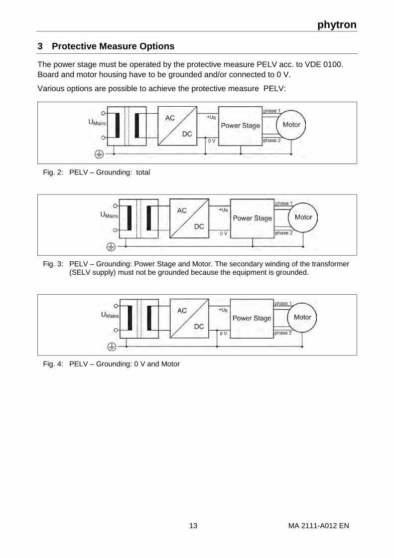
3 Protective Measure Options
The power stage must be operated by the protective measure PELV acc. to VDE 0100. Board and motor housing have to be grounded and/or connected to 0 V.
Various options are possible to achieve the protective measure PELV:
Fig. 2: PELV – Grounding: total
Fig. 3: PELV – Grounding: Power Stage and Motor. The secondary winding of the transformer (SELV supply) must not be grounded because the equipment is grounded.
Fig. 4: PELV – Grounding: 0 V and Motor

Manual ZMX+
MA 2111-A012 EN 14
If there is no PE clamp on the motor, the 0 V wire must be grounded to complete the protective measure PELV (Fig. 5 and Fig.6):
Fig. 5: PELV – Grounding: 0 V and Power Stage
Fig. 6: PELV – Grounding: 0 V
Protective measure PELV for application of the +UB should not exceed 70 VDC or 50 VAC in a dry environment (environmental conditions 3 acc. to IEC 61201).
The supply transformer must be constructed with reinforced or double isolation between supply and secondary winding (acc. to EN 61558).
Only use motors which are checked to EN 60034-1 (500 VAC/1 minute).

phytron
15 MA 2111-A012 EN
4 Design Requirements
4.1 Electromagnetic Compatibility (EMC)
4.1.1 Remarks
DANGER
Risk of injury by interference of signals and devices!
Perturbed signals can cause equipment to react unexpectedly.
• Connect the power stage to the EMC requirements.
• In electrically noisy environments ensure the correct execution of the EMC measures. Disregarding these precautions can cause death, serious injuries or material damages.
A condition for the adherence to the indicated limit values is a EMC-compatible structure. Depending upon application better results can be obtained by the following measures:
• Power choke connected downstream. You receive data of current harmonic on request.
• External line filter connected downstream, in particular to conform to the limits when using long motor cables.
• Special EMC compatible assembling, e. g. in a closed switching cabinet with 15 dB damping of the emitted interference.
ATTENTION
Risk of failure!
Step errors can occur in case of sudden supply voltage drops. An absolute monitoring of the step accuracy is ensured with a superior measuring system using e. g. an encoder.

Manual ZMX+
MA 2111-A012 EN 16
4.1.2 EMC Measures
EMC Measures Effect
19“ rack mounting Use the front panel with the mounting screws, the front panel ensures large contact to the 19“ rack.
Good conductivity due to planar contacts.
Fit switching devices such as contactors, relays or solenoids with interference or spark suppressors (e. g. diodes, varistors, RC elements).
Reduction of mutual interference.
Mount power and control components separately.
Reduction of mutual interference.
Cabling Keep cables as short as possible. No “safety loops“.
Avoidance of capacitive and inductive interference
Connect the shielding of all shielded cables to the 19“ rack by the cable clamps to a large area on the rear panel of the rack.
Reduction of EMC emissions.
Lay the cables spatially separated from each other:
• signal and power cables
• power and master cables
• line filter input and output cables
Avoidance of mutual interference.
Ground a large surface area of the shieldings of digital signal cables.
Stray interference on control cables, reduction of emissions.
Power supply Protective circuit to mitigate over voltage or lightning strikes.
Protection of damage by over voltage.

phytron
17 MA 2111-A012 EN
Preset for EMC: Motor cable
The motor cable is a source of interference and must be carefully laid.
Use the cables recommended by phytron. They are tested for EMC safety and are suitable for movement.
The motor and the encoder cable of the driving system must be connected to a large surface area of the output of the control cabinet and the motor with a low resistance.
• Connect the motor cables without interruption (don’t use switching elements) from the motor to the device. If a cable must be interrupted, use shielding connections and metal housings to avoid interferences.
• Lay the motor cable at a distance of at least 20 cm from the signal cables. If they are laid closer together, motor cable and signal wiring must be shielded and grounded.
• Use potential equalization cables with suitable cross section when the cables are long.
Potential equalization cables
Connect the shielding on all sides for protection from interference.
The difference of potential can cause incorrect currents on the shielding and must be avoided by potential equalization cables.

Manual ZMX+
MA 2111-A012 EN 18
4.2 Shielding
To avoid interference affecting the wires and instruments installed close to the drive system, we recommend the use of shielded cables.
The plug-in board, where the ZMX+ is installed, should be connected to the ground by a central earthing tab.
Fig. 7: Motor cable shielding

phytron
19 MA 2111-A012 EN
4.3 Insulation Overview
Fig. 8: ZMX+ Insulation
WARNING Injury or damage by overvoltage! The power stage must be operated with protective measure PELV. The transformer should be constructed with reinforced or double isolation.
The isolation of the ZMX+ fulfils the requirements of a basic isolation for non-mains circuits for voltages up to 141 V acc. to EN 50178. The device has been designed for degree of pollution 2 acc. to EN 50178.
The IO signals on the connectors are safely electrically isolated by optocoupler. The signals RS 485 on the ServiceBus connectors are electrically isolated from the motor voltage by a separate DC/DC converter (withstand voltage 800 VDC).
Devices connected to ZMX+ for control or communication should have reinforced or double isolation acc. to EN 50178.

Manual ZMX+
MA 2111-A012 EN 20
4.4 Cables
Overview:
max. cable length [m]
min. cross section [mm2]
shielded, grounded on all sides
twisted pair
Motor cable The length depends on the cable resistance: Rcable < 0.2 x Rphase
Dependent on the maximum current of the motor and the motor cable length is suitable:
25 0.1 per 1 Ampere motor current X X
50 0.2 per 1 Ampere motor current X X
Signal interface 100 0.14 X
ServiceBus cable
2 –
Motor cable:
Motor cable length Min. cable cross section for phase currents
up to 3 Ar.m.s. from 3 to 6.5 Ar.m.s.
up to 10 m 1.0 mm2 1.0 mm2
10 m to 25 m 1.0 mm2 1.5 mm2
25 m to 50 m 1.5 mm2 2.5 mm2

phytron
21 MA 2111-A012 EN
4.5 Calculation of the Supply Unit
Consider the following instructions for calculation of the supply unit:
1. If the cables from the supply unit to the ZMX+ are longer than 50 cm, a capacitor with about 47 μF/100 V must be connected in parallel to the connector as far as possible. The capacitor must be suitable for switching applications and have a low ESR (Equivalent Series Resistance).
2. Transformer, load capacitor: Transformer: U = 50 VAC I = 5A Load capacitor: C1 = 4,700 μF The power indications for the transformer and the load capacitor are "worst-case" values, i. e.: computed for a maximum motor power, permanent boost function activation and a 100 % load factor. The actual values must be determined for the real operating conditions. For the load capacitor, a value of 1,000 μF per Amp of motor current can be used. The thermal limit values of the transformer must never be exceeded. The internal resistance of the supply module must be good enough to avoid a DC voltage drop of more than 15 % below the peak value, at maximum load.
The transformer must be constructed with reinforced or double isolation. The secondary winding of the transformer must not be grounded (SELV supply).
3. Rectifier:
The rectifier must be able to dissipate losses up to 2 Watts per Amp. If necessary, mount a heat sink.

Manual ZMX+
MA 2111-A012 EN 22
4.6 Mains Supply Unit
The ZMX+ power stage can be supplied by means of an unregulated filtered DC voltage from 24 to 70 VDC.
Operating voltage range: 24 to 70 VDC
Nominal voltage: 70 VDC
The voltage must not drop under 22 V and rise over 80 V, not even for a short time (> 1 msec). If the external voltage falls below 22 V or rises over 80 V, the ZMX+ detects an error.
Fig. 9: Mains supply unit
For calculation and connection of the supply unit, the following instructions must be followed:
• The transformer must be constructed with reinforced or double isolation.
• i
The calculation of the F2 fuse depends on the preset phase current and the motor load:
Recommended values: Phase current Fuse
<= 1 A T2A 2 A T4A 3 A T6A 4 A T8A 5 A T10A
>= 6 A T12A
• For the load capacitor, a value of 1,000 μF per Amp of motor current should be calculated.
• Use shielded cables for DC supply.

phytron
23 MA 2111-A012 EN
5 Technical Data
5.1 Mechanical Data
Type Standard Euro Board format 96 x 146 mm
Pluggable to the Phoenix adaptor SKBI 64/F-48 (Ident-No. 2264093)
Front plane 3 U / 5 HP
Weight with front plate about 450 g
Mounting Mounting in 19"/3 U rack All connectors are led through to a 32 pin connector (type D) or 48 pin connector (type F) according to DIN 41612 depending on the version.
Fig. 10: Dimensions

Manual ZMX+
MA 2111-A012 EN 24
5.2 Electrical Data
Supply voltage Unregulated filtered DC voltage from 24 to 70 VDC
Nominal voltage 70 VDC
Reinforced or double isolation between mains and secondary circuit
Stepper motor Two phase stepper motors with 4, 6 or 8 lead wiring scheme
Winding resistance between 0.1 and 10 ohm
Winding inductance 0.5 to 10 mH per phase
Step resolution
Rotary switch mode
The step resolution can be set by the rotary switch:
1/1, 1/2, 1/4, 1/5, 1/8, 1/10, 1/20 of a full step.
ServiceBus mode The step resolution is programmable: 1/1, 1/2, 1/2.5, 1/4, 1/5, 1/8, 1/10, 1/16, 1/20, 1/32, 1/64, 1/128, 1/256, 1/512 of a full step.
Phase currents
Rotary switch mode
Run current can be individually set by the rotary switch.
Stop current is 50 % of the run current.
With the Range rotary switch (fine and wide) the run current between 2 ranges can be switched.
Rotary switch position
ON = fine OFF = wide
without Boost: with Boost:
0.1 to 0.8 Ar.m.s. 0.15 to 1.1 Ar.m.s.
0.2 to 1.5 APeak
0.7 to 5.0 Ar.m.s. 0.9 to 6.5 Ar.m.s. 1.3 to 9 APeak
ServiceBus mode Run current is programmable from 0 to 6.5 Ar.m.s. in 0.1 A steps.

phytron
25 MA 2111-A012 EN
Inputs The logic of the inputs can be defined by rotary switch (on the board) or by ServiceBus.
CONTROL PULSES Maximum step frequency: 750 kHz Pulse width > 1 µs to ensure control pulses reliability
DIRECTION The motor direction is inverted by input activation.
BOOST In rotary switch mode: The run current is increased by about 30 % on input activation.
Boost current is programmable in the ServiceBus mode.
DEACTIVATION Both motor phases are switched off when the input is activated.
RESET The power stage is reset to the defined initial state. A signal basic position is generated for each reset.
STEP RESOLUTION If this input is activated and the step resolution is preset by the rotary switch, the step resolution is positioned one step below.
Examples for a 200-step motor:
Rotary switch setting
FS HS 1/2.5 1/4 1/5 1/8 1/10 1/20
Steps 200 400 500 800 1000 1600 2000 4000
Input not active or not wired
FS HS 1/2.5 1/4 1/5 1/8 1/10 1/20
Input active FS FS HS 1/2.5 1/4 1/5 1/8 1/10
The input may not be changed during operation!

Manual ZMX+
MA 2111-A012 EN 26
Outputs Electrical isolated by optocoupler, open collector type
Imax = 20 mA, Umax = 45 V, UCE sat at 20 mA < 0.6 V
BASIC POSITION Zero crossing of the integrated ring counter is indicated; active LOW
Full step
Half step
1/2,5 step
1/4 step
1/5 step
1/10 step
1/20 step
every 4th control pulse
every 8th control pulse
every 10th control pulse
every 16th control pulse
every 20th control pulse
every 40th control pulse
every 80th control pulse
ERROR Supply voltage < 22 VDC
Over temperature (T > 90 °C):
If the permissible heat sink temperature is exceeded, the power stage is deactivated. The LED goes to red.
Over current, short circuit > 30 A for a short time
An error signal deactivates the power stage.
ServiceBus connector 6 pin connector, type Tyco Electronics 2-1761605-1/609-0607
Connector 32 pin VG connector acc. to DIN 41612, type D
48 pin VG connector acc. to DIN 41612, type F

phytron
27 MA 2111-A012 EN
6 Installation
6.1 Mechanical Installation
DANGER
Danger of electric shock by foreign particles or damage!
Loose conductive parts inside the device or damages can cause parasitic voltage.
Don´t use faulty equipment.
WARNING
Danger of damage of system parts by hot surfaces!
The heat sink on the device can heat up to more than 105 °C depending on the operation.
Avoid touching the hot heat sink.
Ventilation:
Consider the following remarks before installation the power stage into a 19“ rack:
• Sufficient cooling of the device by a fan. Avoid heat accumulation.
• Don´t install the device close to heat sources and on combustible materials.
• The heated air flow from other devices and components doesn’t result in excessive heating of the cooling air.
• The device switches off by operation over the thermal limit because of over temperature.
Control cabinet:
The control cabinet must be dimensioned in such a way that all devices and components inside can be firmly mounted and wired in the line with EMC requirements.
The ventilation of the control cabinet must dissipate the heated air flow of all mounted devices and components inside.

Manual ZMX+
MA 2111-A012 EN 28
6.2 Electrical Installation
i The ZMX+ power stage is designed for operation in a 19“ rack!
Risk of failure!
The connection wires to the connector must be connected with all specified pins. Example: + UB is connected to the pins 8a, 8c, 10a and 10c (type D) or pins 8z, 8d, 10z and 10d (type F).
6.2.1 Motor connection
The following chapter describes how to wire different types of two phase stepper motors.
ZMX+ stepper motor power stages may be connected to stepper motors with 0.1 to 9 APeak phase current.
The stepper motor winding resistance should be less than 10 ohm for full power.
The winding inductance of one phase should not be lower than 0.5 mH.
Stepper motors with 8 leads can be connected with the windings wired in parallel (1) or series (2).
For 6-lead stepper motors, wiring scheme (3) with series windings is recommended.
If wiring scheme (3) cannot be used because of the motor construction, the motor may be operated with only two of the four windings energized according to wiring scheme (5).
Damage of the power stage!
5-lead stepper motors must not be connected to the ZMX+. Both 5-lead stepper motor and ZMX+ might be damaged.

phytron
29 MA 2111-A012 EN
Motor time constant τ:
RL= τ applies to the electric motor time constant τ.
The total inductance Ltotal is equal to the winding inductance in a parallel circuit, because of interlinked inductances. Ltotal= 4 x L applies to a series circuit.
The result is an equal motor time constant τ for a serial and a parallel circuit:
Circuit series parallel Resistance Rtotal 2 x R
2R
Inductance Ltotal 4 x L L Motor time constant τ
RL x 2
R x 2L x 4
series ==τ R
L x 2R/2L= τparallel =

Manual ZMX+
MA 2111-A012 EN 30
6.2.2 Wiring Schemes
Fig. 11: Connection diagrams for 4-, 6- and 8- wire stepper motors

phytron
31 MA 2111-A012 EN
6.3 Connector
6.3.1 ServiceBus Connector
The ZMX+ power stage is connected to the 6 pin ServiceBus connector in the ServiceBus mode by suitable cables.
RS 485 Bus CAN Bus*)
Fig. 12: ServiceBus connector type Tyco Electronics 2-1761605-1/609-0607
6.3.2 Connectors
Fig. 13: 32 pin VG connector, type D acc. to DIN 41612
*) CAN2 is not used in the actual SW.

Manual ZMX+
MA 2111-A012 EN 32
Fig. 14: 48 pin VG connector, type F acc.to DIN 41612
Differentiation of the GND pin assignment:
ZMX+ version 32 pin VG connector 48 pin VG connector
With electrical isolation
Pin 30a,30c,32a: 0 V Pin 32c: GND_Opto
Pin 30d,30z, 32z: 0 V Pin 32d: GND_Opto
Without electrical isolation
Pin 30a,30c,32a,32c: 0 V
Pin 30d,30z, 32d,32z: 0 V

phytron
33 MA 2111-A012 EN
7 Putting into Service
7.1 LED Display
The LED indicates the status of the power stage by color changes and blinking:
in Rotary switch mode in ServiceBus mode
LED lights up permanently blinks
Ready
The power stage is ready.
Busy
Control pulses are received by the controller.
Fault A monitoring circuit responded:
Over current: > 30 A
Under voltage: < 22 V
Over temperature: >90 °C
Reset/ Disabled
Input RESET is active. Input DEACTIVATION is active.

Manual ZMX+
MA 2111-A012 EN 34
7.2 Rotary Switches
The rotary switches on the front side are used to:
- set the run current IRun
- set the step resolution and the preferential direction by Step rotary switch
- address the power stage Address rotary switch.
Fig. 15: 16-step rotary switch: Setting 0...F
7.3 DIP Switches
The current range and the ServiceBus can be selected by the DIP switches at the front side.
Fig. 16: DIP switches at the front side
The DIP switches on the board input logic, overdrive and output ERROR are defined.
Fig. 17: DIP switches on the board

phytron
35 MA 2111-A012 EN
7.4 DIP Switch Setting
The Range DIP switch on the front side is used for changing the current range. SB active activates the ServiceBus mode.
Function Position OFF
Position ON
1 Current range selection [Ar.m.s.]
Wide: 0.7 to 5.0
Fine: 0.1 to 0.8
2 ServiceBus off on
Risk of power stage failure!
The ServiceBus mode is activated exclusively by setting the SB active DIP switch to “ON”.
The following functions can be adjusted by the DIP switches on the board:
Function Position OFF Position ON
1 Input logic positive negative
2 Overdrive deactivated activated
3 Output ERROR NCC NOC
4 n.c. – –
The function Overdrive is described in chap. 11.3.

Manual ZMX+
MA 2111-A012 EN 36
7.5 Rotary Switch Mode
The run current is adjusted by the IRun rotary switch, the step resolution and preferential direction by the Step rotary switch.
For fine run current setting you can change between two ranges (wide or fine). Boost increases the run current by 30 %.
Rotary switches
Switch setting
Run current [Aeff] IRun
Step resolution/ Preferential direction Step
Switch setting
ZMX+ versions
without electrical isolation
with electrical isolation fine wide
0 0.12 0.7 Full step + – 1 0.17 1.0 Half step + – 2 0.21 1.3 1/2,5 + – 3 0.26 1.6 1/4 + – 4 0.31 1.8 1/5 + – 5 0.36 2.1 1/8 + – 6 0.40 2.4 1/10 + – 7 0.45 2.7 1/20 + – 8 0.50 3.0 Full step – + 9 0.55 3.3 Half step – + A 0.60 3.6 1/2,5 – + B 0.64 3.9 1/4 – + C 0.69 4.1 1/5 – + D 0.74 4.4 1/8 – + E 0.79 4.7 1/10 – + F 0.83 5.0 1/20 – +
Factory settings
Important: The current values of this table have been verified with the phytron stepper motor ZSH 87.2/200.8.4. Deviation is possible for other motors.

phytron
37 MA 2111-A012 EN
7.6 ServiceBus Mode
The operation parameters can be set by the serial RS 485 bus connection (ServiceBus) in the ZMX+. If more than one ZMX+ is operated (max.16), the RS 485 bus (4 wire operation) or CAN bus is best choice.
In order to activate the ServiceBus, the ServiceBus active DIP switch must be set to ”ON”.
The Address rotary switch sets the address of the power stage in the ServiceBus.
Important: Each address (0...F) must only be used once!
Read ServiceBus manual for more information about the ServiceBus instruction code.
The connection of the ZMX+ power stage acc. to RS 485 (4 wire operation):
Fig. 18: Connection PC -> ZMX+ via USB/RS 485 converter
Fig. 19: Connection PC -> ZMX+ with RS 422/RS 485 interface

Manual ZMX+
MA 2111-A012 EN 38
The ZMX+ power stage connection acc. to CAN:
The ZMX+ power stage is designed as a slave device for connection to a superior controller or PC. The parameterization is made via CAN bus to the controller. The bus has to be connected by a physical bus termination at each end. The controller terminates on one side, on the other side a termination resistor must be connected.
Fig. 20: Connection PC/Controller -> ZMX+ with CAN bus interface

phytron
39 MA 2111-A012 EN
7.7 Checking the Installation
The following steps check the correct installation and hidden transport damages of the ZMX+ power stage:
1. Connect the ZMX+ acc. to ”Protective Measure” in chap. 3. 2. Select the designated current range – fine or wide – with the Range DIP switch. 3. The DIP switches (on the side) are set as follows:
4. For setting the rotary switches see the table in chapter 7.5 ”Rotary Switch Mode”:
• IRun rotary switch: Setting of the designated run current • Step rotary switch: Selecting the step resolution and preferential direction
5. Motor, supply voltage and signal lines are connected via connector by the mating connector or in the 19“ rack.
6. Connect the input signals to the input CONTROL PULSES. 7. Switch on the power supply of the ZMX+.
As soon as the ZMX+ is supplied with voltage and no error occurs the LED shines green.
8. Testing the signals: Check the holding torque of the motor by trying to rotate the motor shaft by hand. An active motor can’t either be rotated or only with difficulty.
9. Apply the control pulses and check whether the motor is moving. 10. Invert the polarity of the direction signal by the Step rotary switch and set the steps for
the motor. The direction of rotation must change. 11. If there is no reaction of the power stage, the input logic has to be inverted by the DIP
switch (on the side).

Manual ZMX+
MA 2111-A012 EN 40
8 Functions
8.1 Inputs
The logic of the inputs CONTROL PULSES, DIRECTION, BOOST, DEACTIVATION and RESET can be defined by the DIP switches on the board or by ServiceBus.
Permissible input voltage range: 0 to 30 VDC
Input logic examples by input wiring:
1. Connecting + and ground
2. Connecting ground and high impedance
3. Connecting + and high impedance
‚Input logic‘ DIP switch: Changing of the logic functions:
positively and negatively only negatively (ON Position)
only positively (OFF Position)
Input functions!
Example 1 only ensures the inverting of the input logic!
The limit switching value for the inputs CONTROL PULSES, DIRECTION, BOOST, DEACTIVATION is
Input logic Limit switching value
positive > 4 V
negative < 2.5 V

phytron
41 MA 2111-A012 EN
ZMX+ version with “electrical isolation”:
The controller inputs CONTROL PULSES, BOOST, DIRECTION, DEACTIVATION, STEP RESOLUTION and RESET are isolated by optocoupler from the power supply (+UB) of the ZMX+. An optimal transient suppression is reached between controller and main circuit.
Fig. 21: Input circuit “electrical isolation”
ZMX+ version without ”electrical isolation”:
The inputs are wired without optocoupler and GND is connected to GND_Opto by hardware.
Fig. 22: Input circuit “without electrical isolation”

Manual ZMX+
MA 2111-A012 EN 42
8.1.1 CONTROL PULSES
Maximum step frequency: 750 kHz
Pulse width > 1 µs to ensure control pulses reliability
The clock pulse of at least 1 µs causes one motor step. The step is done with the first clock pulse.
ZMX+ version DIP switch 1 input logic High Low
without electrical isolation
ON _ The run current is set with the falling edge and the step is done.
OFF The run current is set with the rising edge and the step is done.
_
with electrical isolation
ON The run current is set with the rising edge and the step is done.
_
OFF _ The run current is set with the falling edge and the step is done.
The control pulses sequence must not suddenly start or stop, if the control pulse frequency is higher than the start/stop frequency of the motor. Misposition of the motor would be the result.
The start/stop frequency is defined as that frequency, from which a stepper motor can start from standstill without losing a step. Typical values for the start/stop frequency are 200 to 2000 Hz. The exact value depends on the load torque and the load inertia on the motor shaft.
If the motor is to be operated above the start/stop frequency range, the indexer has to generate frequency ramps to accelerate and decelerate the motor.
Current delay time:
After the last control pulse the stop current is activated after a time. The time after the last control pulse until the change to the stop current is called current delay time. In rotary switch mode the current delay time is set to 40 ms default value. In ServiceBus mode the current delay time is programmed as parameter and saved in the ZMX+ (see chap. Technical Glossary).
i
If the control pulses voltage decreases under 5 V, the maximum control pulse frequency (750 kHz) can be reduced. The higher this voltage so much higher the possible step frequency.

phytron
43 MA 2111-A012 EN
8.1.2 BOOST
If the input is activated, the ZMX+ changes to boost current. The power stage increases the run and stop current by 30 % in the rotary switch mode. As long as the BOOST input is energized, the run and stop current will always be 30% higher.
The boost current can be programmed by the user in ServiceBus mode (from 0 to 6.3 Ar.m.s.).
Thus, a higher torque can be reached during the acceleration and deceleration time of the motor by changing to boost current.
Also see chapter Technical Glossary.
8.1.3 DEACTIVATION
If the input is energized, the motor current is disconnected.
This input is useful, for instance, for service operations to switch the power stage off, without having to disconnect it physically from the mains. Now it is possible to rotate the motor slowly by hand.
Function of the DEACTIVATION input!
The DEACTIVATION input must not be used to replace emergency stop circuit requirements!
The DEACTIVATION input may only be energized during standstill of the motor axis.
The function deactivation may also be used to avoid the inevitable noise emissions of the power stage, e. g. if you have to perform sensitive electrical measurements in the environment of the device.
DIP switch 1 Input logic
High Low
ON Power stage deactivated No deactivation
OFF No deactivation Power stage deactivated

Manual ZMX+
MA 2111-A012 EN 44
8.1.4 RESET
If the input is activated, all error signals and the ring counter are reset. The ring counter is set to basic position. Both motor phases are energized by the same current value in basic position independent of the step resolution.
Fig. 23: Motor phases in basic position (half step)
After activation of the reset signal, the power stage will enable the ready signal approximately 500 ms later.
DIP switch 1 Input logic
High Low
ON Reset activated no Reset
OFF no Reset Reset activated

phytron
45 MA 2111-A012 EN
8.1.5 DIRECTION
This signal changes the motor direction which is defined by the motor wiring and the manufactorer’s specifications.
WARNING
Changing of the input signal!
A change of the signal is only allowed when the stepper motor is at standstill or driven with a speed within the start/stop range.
The signal may not change 1 μs before and up to 4 μs after the clock pulse. Changing the direction at higher speed causes step loss or standstill of the motor.
In the rotary switch mode the preferential direction can be changed by the Step rotary switch (see table in chap. 7.5).
In the ServiceBus mode the preferential direction can be programmed. (see ServiceBus manual).

Manual ZMX+
MA 2111-A012 EN 46
8.1.6 STEP RESOLUTION
Activating or deactivating this input switches from one step resolution to the other.
If the step resolution is fixed by rotary switch, the activation of the input STEP RESOLUTION positiones the step resolution one stage below.
Example for a 200 step motor:
Setting by rotary switch FS HS 1/2.5 1/4 1/5 1/8 1/10 1/20
Steps 200 400 500 800 1000 1600 2000 4000
Input STEP RESOLUTION positive or not wired
FS HS 1/2.5 1/4 1/5 1/8 1/10 1/20
Input STEP RESOLUTION negative
FS FS HS 1/2.5 1/4 1/5 1/8 1/10
WARNING
Changing the step resolution during operation might damage the power stage!
The input STEP RESOLUTION must only be changed before the first clock pulse has arrived after power on or resetting the power stage.
Observe the limit switching value of this input! See chap. 8.1 !
In the ServiceBus mode the step resolution can be programmed. (see ServiceBus manual).
phytron
47 MA 2111-A012 EN
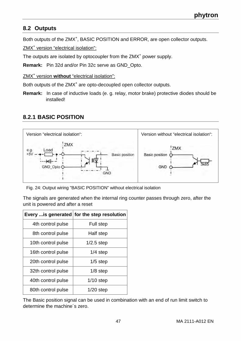
8.2 Outputs
Both outputs of the ZMX+, BASIC POSITION and ERROR, are open collector outputs.
ZMX+ version “electrical isolation”:
The outputs are isolated by optocoupler from the ZMX+ power supply.
Remark: Pin 32d and/or Pin 32c serve as GND_Opto.
ZMX+ version without “electrical isolation”:
Both outputs of the ZMX+ are opto-decoupled open collector outputs.
Remark: In case of inductive loads (e. g. relay, motor brake) protective diodes should be installed!
8.2.1 BASIC POSITION
Version “electrical isolation“: Version without “electrical isolation“:
Fig. 24: Output wiring ”BASIC POSITION” without electrical isolation
The signals are generated when the internal ring counter passes through zero, after the unit is powered and after a reset
Every ...is generated for the step resolution
4th control pulse Full step
8th control pulse Half step
10th control pulse 1/2.5 step
16th control pulse 1/4 step
20th control pulse 1/5 step
32th control pulse 1/8 step
40th control pulse 1/10 step
80th control pulse 1/20 step
The Basic position signal can be used in combination with an end of run limit switch to determine the machine´s zero.

Manual ZMX+
MA 2111-A012 EN 48
8.2.2 ERROR
Version “electrical isolation“ Version “without electrical isolation“
Abb. 1: Output wiring diagram
This output opens in case of the error messages: under voltage, over current/short circuit and over temperature. The drive is deactivated to avoid error elimination or cooling.
An error message can be reset after damages. The power stage can be reset by the input RESET or in ServiceBus mode.

phytron
49 MA 2111-A012 EN
9 ESD Protective Measures
Each product is tested before delivery and submitted to an endurance test run. To eliminate failures due to electrostatic destruction (ESD), a great many protective measures have been implemented throughout the entire manufacturing process - from incoming material to outgoing products.
When handling components, ESD protection measures (e. g. EN 61340-5) must be applied. All products returned to our plant must be packaged according to ESD protection specifications.
Our warranty does not cover failures due to incorrect handling or return packaging which does not conform to ESD specifications.

Manual ZMX+
MA 2111-A012 EN 50
10 Warranty and Trade Marks
10.1 Warranty
The ZMX+ power stages are subject to legal warranty. phytron will repair or exchange devices which show a failure due to defects in material or caused by the production process. This warranty does not include damages which are caused by the customer, as there are, for example, not intended use, unauthorized modifications, incorrect handling or wiring.
10.2 Trade Marks
In this manual several trade marks are used which are no longer explicitly marked as trade marks within the text. The lack of these signs may not be used to draw the conclusion that these products are free of rights of third parties. Some product names used herein are for instance.
• ServiceBus-Comm is a trade mark of Phytron GmbH.
• Microsoft is a registered trade mark and WINDOWS is a trade mark of the Microsoft Corporation in the USA and other countries.

phytron
51 MA 2111-A012 EN
11 Technical Glossary
11.1 Boost
The motor torque required during acceleration and deceleration is higher than that required during continuous motor operation (fmax). For fast acceleration and deceleration settings, (steep ramps), the motor current is too high during continuous operation and results in motor overheating. However, a lower phase current results in longer acceleration and deceleration ramps.
Therefore, different phase currents should be used:
• Continuous operation: run current
• During acceleration and deceleration: Boost current The Boost signal is activated by the superior controller. While input BOOST is energized, a 30 % higher current is flowing.
In the ServiceBus mode the boost value is programmable from 0 to 6.3 Ar.m.s.
Fig. 25: Boost

Manual ZMX+
MA 2111-A012 EN 52
11.2 Current Delay Time
After the last control pulse the stop current is activated after a time. The time after the last control pulse until the changing to the stop current is called current delay time.
We recommend to specify tDelay so that the motor’s oscillations are decaying after the last motor step and mispositioning is avoided.
In Rotary switch mode the current delay time is set to 40 ms.
In ServiceBus mode the delay time can be programmed from 1 to 1000 ms in 15 steps.
Automatic change from run to stop current:
The ratio between both phase currents remains equal in the respective current feed pattern. Changing from run to stop current is achieved synchronously. In the following figure the next motor step follows after every rising control pulse edge:
Fig. 26: Decrease to stop current after the last control pulse (full step)
Decreasing to stop current has the following advantages:
• Motor and power stage heating is reduced.
• EMC is improved because of smaller current values.

phytron
53 MA 2111-A012 EN
11.3 Overdrive
Power stages can compensate the phase current decrease in the upper speed range by the Overdrive function which is independent of the motor type.
Overdrive is a dynamic boost function, which will be automatically switched on.
With increasing step frequency the stepper motor phase current decreases, caused by the counter electromotive force of the motor. The amplitude of the current shape is smaller and the motor looses torque. The Overdrive function works against the reducing of the torque by increasing the r.m.s. phase current automatically by a factor of 2 (generating a rectangle function). It compensates the decrease of the torque. If the speed decreases, the Overdrive is automatically switched off. The input entire pulse, with which the Overdrive function is switched on or off depends on the step resolution:
Step resolution Input control pulse frequency
Overdrive on at > [kHz]
Overdrive off at < [kHz]
1/1 1.8 kHz 1.6 kHz
1/2 3.6 kHz 3.2 kHz
1/4 7.2 kHz 6.5 kHz
1/5 9 kHz 8.1 kHz
1/10 18 kHz 16.2 kHz
1/20 36 kHz 32.4 kHz
The Overdrive function is activated by a jumper, a switch or the ServiceBus.

Manual ZMX+
MA 2111-A012 EN 54
12 Index
A
Ambient temperature 12
B
Basic position 44 BASIC POSITION 26, 47 Boost 51 BOOST 25, 43
C
Calculation 21 CAN 5, 37, 38 CONTROL PULSES 25 Control pulses frequency 42 Copyright 2 Current delay time 42, 52
D
DEACTIVATION 25, 43 Delivery 6 DIRECTION 25, 45
E
ERROR 26
H
Handling 11
I Inductivity 28 Inputs 25 Installation 10 Isolation 19
L
Load capacitor 21
M
Motor connection 28 Motor time constant 29
O
Operating mode 7
Outputs 26, 47 Overdrive 53
P
PELV 13 Phase currents 24 Preferential direction 34, 36, 45 Programming 5 Protective measure 13 Putting into Service 39
R
Rectifier 21 RESET 25, 44 Resistance 28 Ring counter 44 Rotary switch 24, 34, 36 RS 485 37
S
ServiceBus 5, 7 ServiceBus connector 26, 31 ServiceBus mode 24 Start/Stop frequency 42 Step resolution 24, 34, 36 STEP RESOLUTION 25, 46 Stepper motor 24, 28 Supply Unit 22 Supply voltage 24
T
Touch voltage 14 Trade marks 50 Transformer 21 Type 23, 31, 32
W
Warranty 50 Weight 23 Winding inductance 28 Winding resistance 28 Wiring scheme 28

Phytron GmbH • Industriestraße 12 • 82194 Gröbenzell, Germany
Tel. +49(0)8142/503-0 • Fax +49(0)8142/503-190 • E-Mail [email protected] • www.phytron.de
Phytron, Inc. • 600 Blair Park Road Suite 220 • Williston, VT 05495 USA
Tel. +1-802-872-1600 • Fax +1-802-872-0311 • Email [email protected] • www.phytron.com