2010 dipti vete all rights reserved - rutgers university
TRANSCRIPT

2010
Dipti Vete
ALL RIGHTS RESERVED

LEVERAGING WIRELESS NETWORK VIRTUALIZATION FOR FLEXIBLE SHARING OF
WLANs
BY DIPTI VETE
A thesis submitted to the
Graduate School - New Brunswick
Rutgers, The State University of New Jersey
in partial fulfillment of the requirements
for the degree of
Master of Science
Graduate Program in Electrical and Computer Engineering
Written under the direction of
Professor D. Raychaudhuri
and approved by
_____________________________________
New Brunswick, New Jersey
October, 2010

ii
ABSTRACT OF THE THESIS
LEVERAGING WIRELESS NETWORK VIRTUALIZATION FOR FLEXIBLE SHARING OF WLANs
By DIPTI VETE
Thesis Director:
Professor Dipankar Raychaudhuri
Providing air-time guarantees across a group of clients forms a fundamental building
block in sharing an access point (AP) across different virtual network service providers.
Though this problem has a relatively simple solution for downlink group scheduling
through traffic engineering at the AP, solving this problem for uplink (UL) traffic presents
a challenge for fair sharing of wireless hotspots. Among other issues, the mechanism for
uplink traffic control has to scale across a large user base, and provide flexible operation
irrespective of the client channel conditions and network traffic loads. In this thesis the
SplitAP architecture is proposed that addresses the problem of sharing uplink airtime
across groups of users by extending the idea of network virtualization. The architecture

iii
discussed in this thesis allows different algorithms to be deployed on it for enforcing UL
airtime fairness across different client groups.
In this thesis, the design features of the SplitAP architecture are highlighted followed by
results from evaluation on a prototype deployed with the two algorithms for controlling
UL group fairness like: (1) Linear Proportional Feedback Control (LPFC) and (2) Linear
Proportional Feedback Control plus (LPFC+). Performance comparisons on the ORBIT
testbed show that the proposed algorithms are capable of providing group air-time
fairness across wireless clients irrespective of the network volume, and traffic type. The
algorithms show up to 40% improvement with a modified Jain fairness index.

iv
ACKNOWLEDGMENTS
First and foremost, I would like to express my gratitude to my advisor, Prof. Dipankar
Raychaudhuri for his constant support, guidance and concern. Despite all his
commitments and responsibilities he always gave me time and guided me whenever I
needed it.
I am deeply indebted to my most valuable mentor & advisor, Gautam Bhanage for his
continuous guidance and motivation throughout the project. I sincerely appreciate all
his efforts, time and contribution to this thesis.
I acknowledge the help that came from Ivan Seskar with the Orbit implementation and
technical guidance. I express sincere gratitude to Chandru Raman for his moral support,
motivation and help throughout this work. Finally, I would like to thank my family and
friends for being with me and supporting me throughout my thesis work.

v
DEDICATION
To My Grand Parents and Parents

vi
ABBREVIATIONS
AP Access Point
VAP Virtual Access Point
WLAN Wireless Infrastructure Local Area Network
ISP Internet service provider
UL Uplink
DL Downlink
MADWIFI Multiband Atheros Driver for Wifi
CSMA Carrier sense multiple access
LPFC Linear Proportional Feedback Control
LPFC+ Linear Proportional Feedback Control plus (advanced)
FTP File Transfer Protocol
MB Mega Byte
IP Internet Protocol
MAC Medium Access Control
Mbps Mega bits per second
TCP Transmission Control Protocol
UDP User Datagram Protocol
ORBIT Open Access Research Testbed for Next-Generation Wireless
Networks

vii
TABLE OF CONTENTS
ABSTRACT OF THE THESIS ................................................................................................... ii
ACKNOWLEDGMENTS........................................................................................................ iv
DEDICATION ........................................................................................................................ v
1 INTRODUCTION AND RELATED WORK............................................................................. 1
1.1 Introduction .............................................................................................................. 1
1.2 Related Work ............................................................................................................ 4
2 NETWORK VIRTUALIZATION ............................................................................................ 7
2.1 WHAT IS VIRTUALIZATION? ...................................................................................... 7
2.1.1 Hardware emulation........................................................................................... 9
2.1.2 Full virtualization................................................................................................ 9
2.1.3 Paravirtualization ............................................................................................. 10
2.1.4. Operating system-level virtualization............................................................. 11
2.2 Leveraging virtualization for networks ................................................................... 12
2.3 Wireless Access Point Virtualization ....................................................................... 12
2.3.1 Why is virtualization needed? ......................................................................... 13
2.3.2 Virtual Access Points (VAPs) ............................................................................ 13
2.3.3 Baseline Throughput Performance with VAP .................................................. 14
3 SPLITAP DESIGN OVERVIEW........................................................................................... 18
3.1 Group Uplink Airtime Fairness: Problem Statement .............................................. 18
3.2 Virtualization Based Design .................................................................................... 20
3.3 SplitAP Controller.................................................................................................... 22

viii
3.4 Client Plugin Design ................................................................................................ 24
3.5 Algorithms for deployment with SplitAP ................................................................ 26
3.5.1 Algorithm(1): LPFC .......................................................................................... 26
3.5.2 Algorithm(2): LPFC+ ......................................................................................... 27
4 EXPERIMENTAL EVALUATION AND RESULTS ................................................................. 28
4.1 Metrics .................................................................................................................... 28
4.2 Baseline Performance With LPFC............................................................................ 29
4.3 Improvement With LPFC+ ...................................................................................... 38
4.4 Performance with Real-time traffic using LPFC+ .................................................... 39
4.5 Comparison: LPFC Vs LPFC+ .................................................................................... 41
5 CONCLUSIONS AND FUTURE DIRECTIONS ..................................................................... 44
REFERENCES ...................................................................................................................... 46

ix
LIST OF FIGURES
Figure 1: A single wireless access point emulating multiple virtual access points. Clients
from different networks associate with corresponding VAPs though they use the same
underlying hardware........................................................................................................... 2
Figure 2.1: Layered abstraction of virtualization [1] .......................................................... 8
Figure 2.1.1: Hardware emulation [1] ................................................................................ 9
Figure 2.1.2: Full virtualization [1] .................................................................................... 10
Figure 2.1.3: Paravirtualization [1] ................................................................................... 11
Figure 2.1.4: Operating system-level virtualization block diagram [1]............................. 12
Figure 2.3.3: Experimental setup for performance evaluation with physical and virtual
access points [15].............................................................................................................. 15
Figure 2.3.3(c): Experimental parameters used with ORBIT nodes [15] .......................... 16
Figure 2.3.3(d): Impact of virtualizing using channel multiplexing approaches. [15] ...... 16
Figure 3.2: A single wireless access point emulating multiple virtual access points. Clients
from different networks associate with corresponding VAPs though they use the same
underlying hardware......................................................................................................... 22
Figure 3.4: Network stack at the wireless client associating with the SplitAP
infrastructure .................................................................................................................... 25
Figure 4.2(a): Varying rate experiment (50 – 50 sharing) – Total Achieved Throughput. 30
Figure 4.2(b): Varying rate experiment (50 – 50 sharing) - Airtime Utilization................ 30
Figure 4.2(c): Varying rate experiment (10 – 90 sharing) – Total Achieved Throughput. 31

x
Figure 4.2(d): Varying rate experiment (10 – 90 sharing) – Airtime Utilization ............... 31
Figure 4.2(e): Varying packet size experiment (50 -50 sharing) – Total Achieved
Throughput ....................................................................................................................... 33
Figure 4.2(f): Varying packet size experiment (50 -50 sharing) – Airtime Utilization ...... 33
Figure 4.2(g): Varying packet size experiment (10 - 90 sharing) – Total Achieved
Throughput ....................................................................................................................... 34
Figure 4.2(h): Varying packet size experiment (10 - 90 sharing) - Airtime Utilization ..... 34
Figure 4.2(i): Varying offered load experiment (50 – 50 sharing) - Total Achieved
Throughput ....................................................................................................................... 36
Figure 4.2(j): Varying offered load experiment (50 – 50 sharing) – Airtime Utilization... 36
Figure 4.2(k): Varying offered load experiment (10 – 90 sharing) – Total Achieved
Throughput ....................................................................................................................... 37
Figure 4.2(l): Varying offered load experiment (10 – 90 sharing) – Airtime Utilization... 37
Figure 4.3: TCP and UDP co-existence in a single slice with LPFC+. Constant UDP traffic of
5Mbps is supported by slice 1, while the Client 2 with FTP transfer and the client 3 with
varying UDP loads share the slice 2. ................................................................................. 38
Figure 4.4: Results for studying performance with realtime traffic using improved LPFC+
algorithm........................................................................................................................... 40
Figure 4.5(a): Comparison of UL airtime group fairness for: LPFC, LPFC+, and a vanilla
system without our SplitAP framework............................................................................ 41
Figure 4.5(b): Comparison of UL throughput for: LPFC, LPFC+, and a vanilla system
without our SplitAP framework. ....................................................................................... 42

1
CHAPTER 1
INTRODUCTION AND RELATED WORK
1.1 Introduction
The onset of ubiquitous wireless systems in the form of inexpensive handheld devices is
expected to lead to an ever increasing deployment of wireless hotspots [12].
Differentiation in the quality of service provided on shared hardware for wireless
Internet Service Providers (ISPs) provides a substantial challenge with more and more
ISPs aiming to provide services at public locations such as airports, cafes and shopping
areas. A mechanism is required to ensure that this access point (AP) sharing will work
across a wide range of client hardware, while providing each user group (clients
belonging to a single ISP) with aggregate air-time commensurate to the revenue
contract of the ISP with the wireless equipment provider. Apart from providing baseline
fairness in terms of air-time across different user groups, other requirements for sharing
WLAN access point hardware across different ISPs include:
(1) Different broadcast domains,
(2) Different levels of security,
(3) Support different protocols above a basic L2 connection,
(4) Ease of deployment, and
(5) Minimum bandwidth loss for resource partitioning.

2
To solve this problem the SplitAP architecture is proposed in this thesis that employs
wireless network virtualization. Network virtualization is a concept derived from the
server systems area of research which has recently been applied to network sharing.
Virtualization is a mechanism that allows for seamless sharing of a particular resource by
using three key features: Abstraction, Programmability and Isolation. Each of these
features is applied as shown in the Figure 1.
Figure 1: A single wireless access point emulating multiple virtual access points. Clients
from different networks associate with corresponding VAPs though they use the same
underlying hardware.
Abstraction allows the users of the system to use the SplitAP architecture with minimal
changes to the client hardware or software. As shown in the Figure 1, virtual access
points (VAPs) [4] are used that are supported by most commodity AP hardware to

3
emulate the functionality of two different physical APs (ISP1, ISP2) with a single physical
AP, thus allowing the use of the client MAC protocols and hardware without making any
changes to them respectively.
In the setup, programmability is provided by allowing the person deploying the
hardware to allocate different UL air-time quotas for individual virtual access points.
Finally, isolation across groups of wireless users is provided through air-time control at
the clients based on the information provided by the SplitAP controller running at the
AP.
Since downlink air-time fairness has been studied previously [6], and a spate of recent
applications such as those supported by web 2.0 [3], peer-to-peer file sharing [18], and
video conferencing have resulted in significantly increased uplink air-time usage, the
problem of uplink air-time control across the virtual networks formed by wireless user
groups is addressed in this thesis. Through the use of a SplitAP prototype discussed
here, the performance of our sample algorithms for providing uplink air-time fairness
across user groups is shown, while providing all of the features discussed above.
Specifically the contributions of this thesis are:
1) Proposal, design and implementation of the SplitAP software architecture based
on the extension of the virtual access point functionality for sharing a single
physical AP across groups of users.
2) Design and evaluation of the LPFC and LPFC+ algorithms for group UL air-time

4
control using the SplitAP setup on commercial off-the-shelf hardware.
3) Extensive evaluation to show that the results obtained on the SplitAP
infrastructure are as per the requirement while achieving the system
performance with minimal overhead.
1.2 Related Work
Among AP based infrastructures, DenseAP architecture proposed in [16], describes a
mechanism for sharing airtime by managing handoffs across APs. Another setup to
share downlink air-time has been discussed for WiMAX radios in [6]. The SplitAP setup
explained in this thesis specifically deals with the problem of providing architecture for
sharing UL air-time of a single AP across multiple WLAN user groups. In terms of the
methodology itself, a comparison of wireless virtualization approaches is presented in
[15]. However, it does not address the problem of fair sharing of UL air-time across
client groups.
In the domain of air-time fairness, a body of work [14], [10], [7], [5] discusses the use of
EDCA parameters such as contention windows and transmission opportunities for
controlling airtime usage across clients. The study in [14] attempts to ensure fairness
across competing uplink stations with TCP traffic using EDCA parameters. Time fair
CSMA protocol proposed in [10] controls minimum contention window size to achieve

5
estimated target uplink throughput for each competing station in multirate WLAN. In [5]
authors suggest that in a proportional fair allocation based on 802.11e EDCA
parameters, equal share of channel time is given to high and low bit rate stations and, as
a result, high bit rate stations can obtain more throughput. Another study in [7]
proposes two control mechanisms for airtime fairness, one using AIFS and the other
using contention window size. The studies in [14], [10], [7], and [5] are based on
simulations.
One study in [17] proposes a Time Based Regulator system that achieves uplink air-time
fairness by ensuring equal "long term" channel occupancy time for every node in the
WLAN. Though this study presents results based on an implementation, it does not deal
with the problems of clients sending traffic with different frame sizes, offered loads, and
sharing of airtime across user groups. The TWHTB system discussed in [8] uses
information on current channel quality to the respective station associated with AP to
schedule downlink transmission to that particular station by limiting frame transmission
rate. However, this scheme does not take into account Uplink flows and corresponding
traffic variations. Another study discussed in [11] discusses an approach where each
station monitors the number of active stations and calculates the target access time
based on this information. The study uses sniffing on the client side, while also requiring
modification of NAV field in the MAC header, and results are based on simulations.

6
In addition none of these studies address the problem of enforcing client-group UL
airtime fairness which is addressed by algorithms run on our SplitAP setup.
Rest of the thesis is organized as follows. Chapter 2 gives a brief overview of what
network virtualization is and how can it be leveraged to solve the problem we are
tackling in this thesis. Chapter 3 discusses the problem of providing uplink air-time
fairness across user groups, and presents the design of our SplitAP architecture. Chapter
4 presents a discussion on the two sample algorithms evaluated with the SplitAP
framework. Chapter 5 presents the results from the system, and finally, chapter 6
discusses the conclusions and future work.

7
CHAPTER 2
NETWORK VIRTUALIZATION
This chapter begins by providing an overview of what virtualization is. This is followed by
a discussion about how this concept is extended to both wired and wireless networks.
This is followed by how the network virtualization is applied for the problem statement
covered in this thesis using the Virtual Access Points (VAPs) feature provided by
MADWIFI driver for atheros chipset to create multiple virtual APs (slices) from one
physical access point. Finally, we conclude this chapter with some basic experiments to
test the performance of VAP.
2.1 WHAT IS VIRTUALIZATION?
Virtualization is a framework or methodology of dividing the resources of a computer
into multiple execution environments, by applying one or more concepts or
technologies such as hardware and software partitioning, time-sharing, partial or
complete machine simulation, emulation, quality of service, and many others [19].
The general process of virtualization is best explained with Figure 2.1. The hardware
machine to be virtualized lies at the bottom of the virtualization solution. Virtualization

8
may or may not be supported on this machine directly. On top of the actual hardware
resource there is a hypervisor more commonly known as Virtual Machine Monitor
(VMM). This layer acts as an abstraction between the hardware and the operating
system (OS).
Figure 2.1: Layered abstraction of virtualization [1]
If the OS performs the functions of the hypervisor itself, then such operating system is
called the host operating system. The actual virtual machines (VMs) form the topmost
layer of the entire virtualization solution. These VMs are isolated operating systems, and
they function as if the entire host hardware platform is dedicated to each one of them.
These VMs are independent of each other and can have applications associated with
them.
Having understood what virtualization is, we take a look at the different types of
virtualization techniques that are possible [1] -

9
2.1.1 Hardware emulation
In this technique, virtualization is provided by creating virtual machines that emulate
the hardware itself. This technique allows OS to run without making any modifications
to it. The main drawback of this technique is that it is very slow.
Figure 2.1.1: Hardware emulation [1]
Example of hardware emulation is QEMU. Figure 2.1.1 shows the basic architecture of
Hardware Emulation.
2.1.2 Full virtualization
Virtual machine manager is used to mediate between the host machine and guest OS in
this type of virtualization technique.

10
Figure 2.1.2: Full virtualization [1]
This requires some protected instructions to be trapped and managed by the VMM
since the underlying hardware is shared by all the virtual machines (VMs). This
technique also allows the OS to run unmodified. At the same time it does need to be
compatible with the underlying hardware. VMware and z/VM are the examples of this
type of virtualization. This technique is as depicted in Figure 2.1.2.
2.1.3 Paravirtualization
This method is similar to full virtualization; wherein it uses a hypervisor to mediate
access to the hardware; but it requires that the guest operating system has some
virtualization-aware code present in it. Figure 2.1.3 explains this technique. This
mechanism does away with the need to trap any privileged instructions, since the guest
OS is aware of the virtualization process. Paravirtualization comes closest to offering

11
performance that is close to that of an unvirtualized system. Xen and UML make use of
the paravirtualization technique.
Figure 2.1.3: Paravirtualization [1]
2.1.4. Operating system-level virtualization
The final technique as shown in Figure 2.1.4 virtualizes server on the top of the
operating system itself. This method isolates the independent servers from each other,
while supporting the same operating system to be used by them. This can provide native
performance at the cost of changes to the operating system kernel. OpenVz is an
example of operating system-level virtualization technique.

12
Figure 2.1.4: Operating system-level virtualization block diagram [1]
2.2 Leveraging virtualization for networks
Network virtualization provides a powerful way to run multiple networks, each
customized to a specific purpose, at the same time over a shared substrate [21].
Network virtualization is intended to optimize network speed, reliability, flexibility,
scalability, and security. It delivers increased application performance by dynamically
maximizing network asset utilization while reducing operational requirements [22]. It is
said to be especially effective in networks that experience sudden, large, and
unforeseen surges in usage [23].
2.3 Wireless Access Point Virtualization
This section talks about how the virtualization concepts and techniques explained in
previous section are applied for virtualizing a wireless access point.

13
2.3.1 Why is virtualization needed?
Virtualization enables a single machine/node to emulate multiple logical instances of a
required physical/hardware resource within the same or different slices. One of the
main challenges with the radio nodes on ORBIT grid is to provide a setup where multiple
experimenters could run experiments which involve a wireless access point and their
respective stations/clients as a part of their experimentation setup. This configuration is
achieved by using virtual access point (VAP) functionality provided by 802.11 driver that
is further explained in the next section.
2.3.2 Virtual Access Points (VAPs)
A VAP is defined as a logical abstraction that could be run on a physical access point
which then emulates the behavior of a conventional access point to all the client
stations in the WLAN [24]. Using a VAP allows for two or more AP mechanisms to share
the same channel thereby helping channel and energy conservation. In contrast to the
TDMA approach for channel multiplexing, VAPs are more suitable for running short and
long-term experiments with less stringent constraints on the current testbed resources.
The concept of VAPs is incorporated in the 802.11 driver, which operates just above the
MAC layer and below the IP layer. The driver provides the multiple AP abstraction to the
higher layers though it is operating on a single lower layer. Hence all the protocols
operating on the machine are agnostic to the presence of the abstraction.

14
Compared to the TDMA approach, the VAP does not require tight synchronization
among the different experiment nodes. However, this scheme requires traffic shaping
and is limited to fixed star topology wireless networks [15]. Since channel conservation
is of prime importance, we choose to use VAP methodology on the ORBIT grid for
evaluation of air-time fairness provided by SplitAP mechanism.
2.3.3 Baseline Throughput Performance with VAP
Throughput, latency and jitter are usually the three main parameters, which determine
a user’s utilization and experience on a network device. Throughput for individual
experiments in a virtualized environment is expected to be lesser than those under
single user conditions. However, performance under these conditions is largely
contingent on how fairly the resources are shared. A virtualized channel is shared
among multiple users running simultaneous experiments and the end performance can
largely be a function of individual experiment parameters rather than just a fair share
between users. This study was insightful in determining that a VAP provides significant
advantages over a conventional physical access point setup [15].
VAP Overhead
A VAP creates an abstraction of multiple physical access points running from the same
hardware for the stations associating with it. Creation of these logical entities requires
state maintenance and independent management signaling for each of the networks
managed by each VAP. The overheads of maintaining the state of multiple networks at a

15
single hardware device is studied in [15]. The experimental setup is as shown in Figure
2.3.3(a) and Figure 2.3.3(b).
Figure 2.3.3: Experimental setup for performance evaluation with physical and virtual
access points [15]
Figure 2.3.3(a) shows a setup with one AP and all four clients within the same network.
Figure 2.3.3(b) has the same nodes. However, each client belonged to a different logical
network created by the VAPs. Care was taken to ensure that there is no capture within
the network by choosing client nodes such that they had comparable RSSI at the access
point. Results were evaluated for both uplink and downlink performance with a
saturated channel and equal offered load per client. Other experiment parameters were
maintained as shown in Figure 2.3.3(c). Figure 2.3.3(d) plots the observed per client
throughput for uplink and downlink traffic.

16
Figure 2.3.3(c): Experimental parameters used with ORBIT nodes [15]
Figure 2.3.3(d): Impact of virtualizing using channel multiplexing approaches. [15]
Performance of a single client with a single access point was taken as a reference for
comparison. Key observations that were made from the results are:
• As with any time sharing approach, the entire bandwidth (which is seen in the scenario
with 1 client) was shared across 4 clients.

17
• There was a slight deterioration in uplink traffic performance with both the AP and the
VAP as compared to the reference flow with 1 client.
• There was no added deterioration with uplink traffic using VAPs for having clients on
multiple networks, as compared to an AP with all clients in one network. Hence, it was
concluded that the deterioration was seen in both cases, which lead to a net channel
throughput decrease of 9.75%. This decrease for the virtualized scenario as compared to
no vitualization was due to the increased channel contention overhead.
• Downlink overheads for both AP and VAP with 4 clients were negligible as compared
to that with a single client.
• Error bars for both cases show little variance in throughput. Hence it was concluded that
using a VAP adds no conspicuous overhead to the throughput performance of an AP.
This behavior was confirmed by investigating the source code for the MADWIFI driver
where the VAPs are created. The driver does minimal additional processing to
differentiate between the packets received for the different virtual interfaces. The above
study suggests that experiments evaluating aggregate throughput with test setups running
a single AP or multiple VAP should generate comparable results with the channel
utilization being determined by the number of clients [15].

18
CHAPTER 3
SPLITAP DESIGN OVERVIEW
Throughout this thesis the notion of slices is used to refer to the resources allocated to a
group of users belonging to a single ISP. The terms groups or slices will be used
interchangeably henceforth. Our infrastructure enforces fairness in uplink (UL) airtime
usage across slices, thus allowing individual ISPs to fairly share the underlying WLAN
hardware and the corresponding channel. We start with a formal definition of the
problem of sharing UL airtime across a group of users, followed by a conceptual
description of our virtualization based design. Eventually, the details of the algorithms
used for UL airtime allocation are discussed.
3.1 Group Uplink Airtime Fairness: Problem Statement
Consider a set of M client groups (slices) with each group Si having Ni clients. Let the
fraction of UL air time allocated for every slice Si ϵ M, be denoted by Wi. Wi for each
slice is decided during the time of deployment of the infrastructure and can be
dependent on a wide range of criterion like pricing, importance of the group and so on.
If φij denotes the measured UL air time consumed by the client j ϵ Si slice, the fraction of
UL air-time used by every client associated with the access point is calculated as Cij:

19
The condition of group fairness requires that, the total measured UL airtime for all
clients within a slice Si is limited to Wi:
The above condition should be fulfilled while placing no limitation on the individual
values of Cij i.e. all nodes within a single slice Si should be able to share the UL airtime
fairly, independent of the usage on other slices. Hence, in the worst case every client
should be able to utilize UL airtime 0 ≤ Cij ≤ Wi as long as the Equation (2) is not violated
and all clients within Si share the available UL airtime fairly.
Qualitatively summarizing the constraints of the slice/group fairness mechanism:
(1) Flexibility: If the channel usage is below saturation, and there are no hard
guarantees, each client should be able to access the entire available channel time for
the slice,
(2) Within a group: Sharing of UL airtime should be fair and equal,
(3) Scalable: Should work with a large number of clients without significant control
overheads,

20
(4) Adaptable: Should be able to comfortably adapt to changing environment with
dynamic addition or removal of wireless clients, the network load, protocol type and the
channel conditions for individual clients.
Hence, to allow deployment of algorithms that will be able to realize such a group
airtime fairness mechanism, our SplitAP infrastructure will need to provide all needed
control and measurement features while being transparent to the users of the system.
3.2 Virtualization Based Design
We will now discuss how each of the virtualization features is implemented as a part of
our SplitAP architecture.
Abstraction: The functionality of virtual access points is employed and extended which is
available as a standard feature on commercial access points for emulating multiple
virtual access points on a single physical access point while operating on the same
wireless channel [4]. Using this feature the physical AP will be able to broadcast beacons
for independent virtual networks (ISPs). Hence clients belonging to different ISP slices
can see the ESSID of their ISP and associate with it, thereby making client side
connectivity transparent and simple.
Programmability: Each of the ISPs should have independent control of settings in their
network. Using virtual access points, different features can be set per WLANs such as

21
different security policies, broadcast domains, IP settings, independent control of MAC
settings such as aggregation and 802.11e based WMM parameters.
Isolation: Isolation across virtual networks (client groups) is a fundamental requirement
for supporting multiple networks and will be the main topic discussed in this thesis.
Ideally, this could be done through a strict TDMA scheduler across the virtual networks.
However, such a scheduler would require a large change in the MAC mechanism of the
clients, thus making them completely incompatible with other 802.11 based commercial
access points. The SplitAP mechanism1 proposed in this thesis is an incremental design
to the existing 802.11 framework and is currently capable of existing as a stand alone
entity outside of the driver. The functionality in our system is split as shown in the
Figure 3.2.
The SplitAP controller at the AP is responsible for emulating the virtual access points,
accounting of traffic by client groups, and determining the weights of UL airtime for
each group. The client software is responsible for enforcing the commands broadcasted
by the controller and reporting usage statistics like the physical layer rate and the
average packet size reported by the client interface. The remaining discussion will focus
on the implementation of individual components, followed by a brief overview of the
algorithms for providing uplink airtime fairness across the ISP slices.
1 A brief overview of this work is also available in [25].

22
Figure 3.2: A single wireless access point emulating multiple virtual access points.
Clients from different networks associate with corresponding VAPs though they use
the same underlying hardware
3.3 SplitAP Controller
The access point infrastructure runs a multi-threaded ruby controller that performs the
actions described in Algorithm (1). In the controller, sliceID is a unique identifier used for
identifying independent slices owned by different ISPs. The algorithm computes slice UL
Shared
Backhaul
• Emulate VAPs
•Slice traffic accounting
• Calculate per slice client
weight Wk, broadcast Wk
• Receive broadcast Wk
• Controller shaper
• Report statistics
Wireless

23
airtime usage time[sliceID] for every sliceID, by iterating and determining the UL airtime
usage reported by individual clients within every slice sliceID. Based on this estimate, it
determines the offset of the actual slice utilization from the allocated UL airtime
fraction. If this offset is greater than a threshold (Θ), the AP controller uses UDP
broadcast as a means of sending CsliceID to clients to limit control traffic, since the number of
control messages are now dependent on the number of slices rather than number of clients.
Ideally, these CsliceID will be included in the beacons of individual virtual access points, thereby
eliminating the need for a separate signaling mechanism. CsliceID the maximum UL airtime
fraction that can be consumed by any individual client within the slice sliceID. The value
of CsliceID is always chosen as inversely proportional to the UL airtime utilization for that
slice. This fraction of channel time is calculated based on the previously broadcasted
value and the corresponding slice utilization. LPFC and LPFC+ algorithms discussed later
are two means of calculating CsliceID based on current UL airtime utilization numbers and
or the number of associated clients.

24
3.4 Client Plugin Design
In the current design, the client needs to install an application that allows the user to
connect to a SplitAP based wireless service provider. Eventually, to make this application
platform independent, it could be implemented as a web browser plugin that controls
client’s UL traffic based on commands from the controller. The client software stack in
the current SplitAP architecture is as shown in Figure 3.3.

25
Figure 3.4: Network stack at the wireless client associating with the SplitAP
infrastructure
The SplitAP client control and reporting module is responsible for two functionalities:
(1) Determining and reporting client side parameters such as physical layer rate
(through access of the rate table), and average packet sizes by querying the proc
filesystem or using the driver statistics.
(2) Converting the maximum airtime limit enforced by the SplitAP controller to a rate
value, and accordingly controlling the shaping module to rate limit the client. The

26
shaping module is implemented by using the Click [13] modular router that
transparently controls outbound traffic from the interface.
3.5 Algorithms for deployment with SplitAP
The SplitAP design offers a convenient way to deploy different algorithms on the AP for
controlling uplink airtime across slices. Each of the algorithms discussed in this section
are ways to implement the getwt() function discussed in Algorithm (1) and provide the
value CsliceID, which is the maximum airtime that can be consumed by any client in Slice
SsliceID.
3.5.1 Algorithm(1): LPFC
This is a simple linear proportional feedback control (LPFC) based algorithm that uses a
dynamic estimate of the number of clients associated with the AP to calculate the CsliceID.
Information on the number of clients associated with the AP is available in the SplitAP
controller through querying of the proc interface on the AP. The algorithm calculates
CsliceID simply by determining current number of clients in the slice SsliceID and
proportionally splitting the available (quota of) airtime WsliceID among the number of
clients NsliceID within the slice. The SplitAP architecture allows this corrected CsliceID to be
broadcasted every one second or at another interval desired by the ISP using the slice.

27
3.5.2 Algorithm(2): LPFC+
Instead of generating and broadcasting the CsliceID purely based on the slice UL airtime
quota and number of clients in the slice, the LPFC+ algorithm relies on monitoring the
current UL airtime utilization for the slice, which is available through the SplitAP client
reports and appropriately controlling CsliceID. The algorithm selects CsliceID in such a way
that even if the offered load by clients in a slice is not the same, it allows the clients to
increase traffic, by increasing CsliceID until the UL airtime quota for the slice is reached. If
the quota is exceeded (or under-utilized), the LPFC+ controller proportionally reduces
(or increases) CsliceID, the maximum airtime that can be used by any client in the Slice
sliceID. As with the LPFC algorithm, the CsliceID can be broadcasted every one second or
at any other value desired by the ISP owning the slice.

28
CHAPTER 4
EXPERIMENTAL EVALUATION AND RESULTS
All experimental results presented in this evaluation are based on the clients with
Atheros 5212 chipsets, and using Madwifi 0.9.4 [2] drivers. The clients are all operating
in the 802.11a mode with a frame size of 1024bytes, and 54Mbps physical layer rate
unless mentioned otherwise. Traffic is generated with the Iperf tool [1]. We begin with a
brief definition of the metrics used, followed by baseline performance of the LPFC
algorithm and a comparison with LPFC+.
4.1 Metrics
Preliminary evaluations with a small number of clients will be based purely on
comparison of UL airtime allocated to individual slice. Further, in our evaluations, we
modify and use the Jain fairness index [9] for determining weighted UL airtime fairness
across flows and flow groups.
Modified Jain Index: Let the sum of fraction of channel time used by all clients in slice k
be denoted as Ck. Then,

29
The fairness index (I) determines the global variation in channel utilization across slices.
We further scale the airtime by slice quotas to evaluate fairness under saturation with
different slice weights, while also accounting for performance deterioration due to bad
channel quality.
4.2 Baseline Performance With LPFC
To measure the baseline performance with the LPFC algorithm, we consider a setup
with two clients on different slices sending UDP UL traffic using Iperf traffic generator.
Varying Transmission Rates In the first experiment, we vary transmission rates of the
two clients on Slice 1 and 2 as shown on the x-axis in Figure 4.2(a), Figure 4.2(b) Figure
4.2 (c) and Figure 4.2(d). We observe that, in the vanilla case (without the SplitAP
mechanism running the LPFC algorithm), the air-time used by the two clients are
inversely dependent on the transmission rates. Also, the aggregate throughput achieved
using SplitAP framework is slightly higher as against the traditional Vanilla system. This
is a result of statistical multiplexing of packets by the CSMA MAC operating as a part of
the 802.11 DCF mechanism.

30
Figure 4.2(a): Varying rate experiment (50 – 50 sharing) – Total Achieved Throughput
Figure 4.2(b): Varying rate experiment (50 – 50 sharing) - Airtime Utilization

31
Figure 4.2(c): Varying rate experiment (10 – 90 sharing) – Total Achieved Throughput
Figure 4.2(d): Varying rate experiment (10 – 90 sharing) – Airtime Utilization

32
Varying Packet Sizes Now we will vary the packet size of the uplink traffic from each
client to check its impact on the overall sharing of air time at the access point for the
two clients.
As seen in the results in Figure 4.2(f) and Figure 4.2(h), the airtime consumed at the
access point without the use of our scheme (vanilla) is directly dependent on the size of
the packets used by the uplink traffic. Typically, this results from a statistical
multiplexing of packets over the air. However, using our SplitAP infrastructure with the
LPFC algorithm we are able to control uplink traffic in direct proportion to the air time
usage by each client. Our scheme accounts for the extra airtime spent in channel
accesses and PHY/MAC overheads with smaller packet sizes resulting in fair sharing
across the clients and thus virtual networks. This is also evident from the aggregate
achieved throughput results as seen in Figure 4.2(e) and Figure 4.2(g). It is observed that
the aggregate throughput achieved using SplitAP framework is comparable with the
traditional Vanilla system. As before we observe that our infrastructure allows control of
air-time across the clients in a preset 50 - 50 and 10 – 90 percentage. This percentage
could be easily varied.

33
Figure 4.2(e): Varying packet size experiment (50 -50 sharing) – Total Achieved
Throughput
Figure 4.2(f): Varying packet size experiment (50 -50 sharing) – Airtime Utilization

34
Figure 4.2(g): Varying packet size experiment (10 - 90 sharing) – Total Achieved
Throughput
Figure 4.2(h): Varying packet size experiment (10 - 90 sharing) - Airtime Utilization

35
Varying Offered Loads In this experiment, we vary the offered loads across the two
clients. Combinations of offered loads used across the clients are as shown on the x-axis
in the results in Figure 4.2(i), Figure 4.2(j), Figure 4.2(k) and Figure 4.2(l). The maximum
offered load is limited to 33Mbps because the channel saturates at that value of the
offered load when the physical layer rate is 54Mbps. The channel saturates at this
slightly higher value than normal since the Madwifi drivers use fast framing
optimizations to improve performance within allocated txops. However, this does not
affect our evaluation since it is enabled in all measurement cases. The aggregate
throughput achieved using SplitAP framework in this case is slightly deteriorated
compared to the traditional Vanilla system. This is because LPFC algorithm uses
conservative approach and limits airtime of slice 2 (with 33Mbps physical rate) even
though the other client is not using its share. We observe that LPFC scheme limits
airtime of Slice 2, to ensure better fairness as compared to the vanilla case with no
control.

36
Figure 4.2(i): Varying offered load experiment (50 – 50 sharing) - Total Achieved
Throughput
Figure 4.2(j): Varying offered load experiment (50 – 50 sharing) – Airtime
Utilization

37
Figure 4.2(k): Varying offered load experiment (10 – 90 sharing) – Total Achieved
Throughput
Figure 4.2(l): Varying offered load experiment (10 – 90 sharing) – Airtime
Utilization

38
4.3 Improvement With LPFC+
Since the LPFC+ algorithm allows the allocation of slice weights such that within a slice
we may have varying utilization by independent clients, such a mechanism allows for
fair co-existence of transport protocols with different requirements. In this experiment
we have two slices: Slice 1 has a client sending constant UDP uplink traffic, while the
Slice 2 has two clients. The first client in Slice 2 is sending varying amount of UDP uplink
traffic, while the other client in Slice 2 is transferring a 200MB file with a FTP file
transfer. Results from this experiment are as shown in Figure 4.3.
Figure 4.3: TCP and UDP co-existence in a single slice with LPFC+. Constant UDP traffic
of 5Mbps is supported by slice 1, while the Client 2 with FTP transfer and the client 3
with varying UDP loads share the slice 2.

39
We observe that the client on slice 1 is not affected despite one of the clients on Slice 2
using UDP traffic. We also observe that the clients on Slice 2 share the UL airtime. When
the UDP offered load is less at 4Mbps, the FTP transfer is faster and happens at an
aggregate rate of 18.3Mbps. When the UDP offered load on the client increases, the FTP
client reduces its rate, thereby requiring longer time for the FTP transfer completion. It
is important to note that a similar performance could be achieved even by using LPFC
instead of LPFC+. However, in that case the FTP client on slice 2 would always be limited
to a fixed uplink rate thereby resulting in wastage of free bandwidth.
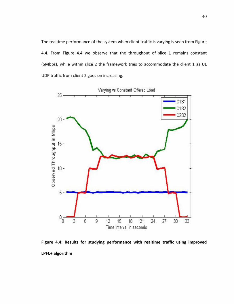
4.4 Performance with Real-time traffic using LPFC+
As explained before, since the LPFC+ algorithm allows the allocation of slice weights
such that within a slice we may have varying utilization by independent clients, such a
mechanism controls the amount of UL and DL traffic load on each slice thus providing
isolation between them. In this experiment we have two slices: Slice 1 has a client
sending constant UDP uplink traffic of 30Mbps and has slice weight WsliceID = 0.2, while
the Slice 2 has two clients with slice weight WsliceID = 0.8. The first client in Slice 2 is
sending constant amount of UDP uplink traffic, while the other client in Slice 2 is sending
varying amount of UDP uplink traffic in steps of 5Mbps. Results from this experiment
are as shown in Figure 4.4.
40
The realtime performance of the system when client traffic is varying is seen from Figure
4.4. From Figure 4.4 we observe that the throughput of slice 1 remains constant
(5Mbps), while within slice 2 the framework tries to accommodate the client 1 as UL
UDP traffic from client 2 goes on increasing.
Figure 4.4: Results for studying performance with realtime traffic using improved
LPFC+ algorithm

41
4.5 Comparison: LPFC Vs LPFC+
In a final experiment we consider a setup with two slices: Slice 1 has a single client
pumping UDP UL traffic at saturation, while Slice 2 has 5 clients associated with it. For
different experiments, varying number of clients 1 - 5 on Slice 2 will send saturation UL
traffic along with the client on Slice 1. In this case we consider the performance of both
LPFC and LPFC+ algorithms, as compared to that without our SplitAP setup (Vanilla).
Figure 4.5(a): Comparison of UL airtime group fairness for: LPFC, LPFC+, and a vanilla
system without our SplitAP framework.

42
A comparison of the measured modified fairness index is as shown in Figure 4.5(a). We
observe that the group fairness index I is always greater than 0.97 with the use of our
infrastructure, while it falls down up to 0.6 in a vanilla system without our setup.
Figure 4.5(b): Comparison of UL throughput for: LPFC, LPFC+, and a vanilla system
without our SplitAP framework.
The throughput measurements in Figure 4.5(b) show that the improvements in fairness
are at the cost of a small decrease in net throughput with LPFC+, thus justifying the use
of our scheme. The throughput performance with our LPFC scheme is less when lesser

43
number of clients on Slice 2 pump traffic. This is because it sees five clients associated
with the slice from the beginning, and presents a conservative estimate of CsliceID which
results in lower throughput. The LPFC+ scheme on the other hand dynamically measures
airtime for every slice and adapts its CsliceID resulting in better performance. It cannot
reach channel capacity since it keeps a 15% tolerance, but is able to divide the
remaining airtime fairly. The 15% tolerance value to prevent the system from reaching
channel capacity was selected since we achieved best performance on our SplitAP
framework with this value while minimizing the wastage of bandwidth based on the
extensive experimental evaluation we carried out.

44
CHAPTER 5
CONCLUSIONS AND FUTURE DIRECTIONS
This study discusses the design of the SplitAP architecture that allows the operator to
deploy a shared physical access point, which is capable of running algorithms that
control UL airtime across user groups. We demonstrate the feasibility of the proposed
architecture by implementing the LPFC and LPFC+ algorithms on a prototype. Results
obtained from the measurements on the ORBIT testbed show a significant improvement
in the group airtime fairness, while resulting in marginal degradation of overall system
throughput.
Future directions include search for more efficient algorithms that can be deployed on
the SplitAP framework. Evaluation of the UL airtime fairness issue for mesh and ad-hoc
wireless network topologies needs to be done. But the VAP mechanism for time-sharing
of physical wireless access point that we have leveraged in this study will not work in
case of mesh and ad-hoc networks. A new distributed control mechanism based on
explicit Time Division Multiple Access (TDMA) based scheduler would be required to
achieve the airtime fairness for these distributed network topologies as against the
current centralized controller with enhanced signaling mechanism. Also, the stand alone
client application of SplitAP architecture could be implemented as a web browser plugin
to make it platform independent. Finally, the slice airtime quota/weight, CsliceID could be

45
included in the beacons of individual VAPs thereby eliminating the need for a separate
signaling mechanism.

46
REFERENCES
[1] Iperf traffic generator. http://sourceforge.net/projects/iperf/.
[2] Madwifi driver. http://www.madwifi.org
[3] Web 2:0 framework. http://tinyurl.com/dqt86.
[4] B. Aboba. Virtual access points, ieee document, ieee 802.11-03/154r1.
http://tinyurl.com/yjjkwpv.
[5] A. Banchs, P. Serrano, and H. Oliver. Proportional fair throughput allocation in
multirate ieee 802.11e wireless lans. Wireless Networks, 13(5):649–662, 2007.
[6] G. Bhanage, R. Daya, I. Seskar, and D. Raychaudhuri. VNTS: a virtual network traffic
shaper for air time fairness in 802:16e slices, 5 2010.
[7] C.-T. Chou, K. G. Shin, and S. S. N. Contention-based airtime usage control in
multirate ieee 802.11 wireless lans. IEEE/ACM Trans. Networking, 14(6):1179–1192,
2006.
[8] R. G. Garroppo, S. Giordano, S. Lucetti, and L. Tavanti. Providing airtime usage
fairness in ieee 802.11 networks with the deficit transmission time (dtt) scheduler.
Wirel. Netw., 13(4):481–495, 2007.
[9] R. K. Jain, D.-M. W. Chiu, and W. R. Hawe. A quantitative measure of fairness and
discrimination for resource allocation in shared computer systems. Technical report,
DEC, September 1984.
[10] T. Joshi, A. Mukherjee, Y. Yoo, and D. P. Agrawal. Airtime fairness for ieee 802.11
multirate networks. IEEE Transactions on Mobile Computing, 7(4):513–527, 2008.

47
[11] D.-Y. KIM, E.-C. PARK, and C.-H. CHOI. Distributed access time control for per-
station fairness in infrastructure wlans. Transactions on Communications, Vol.E89-
B(9):2572–2579, 2006.
[12] K. Knight. Jiwire: Wifi to become predominant connection for mobile users.
http://tinyurl.com/yjukaq9.
[13] E. Kohler, R. Morris, B. Chen, J. Jannotti, and M. F. Kaashoek. The click modular
router. ACM Trans. Comput. Syst., 18(3), 2000.
[14] D. Leith, P. Clifford, D. Malone, and A. Ng. Tcp fairness in 802.11 e wlans.
Communications Letters., Vol.9(11):964–966, 2005.
[15] R. Mahindra, G. Bhanage, G. Hadjichristofi, I. Seskar, D. Raychaudhuri, and Y. Zhang.
Space versus time separation for wireless virtualization on an indoor grid. In proceedings
of NGI, pages 215–222, April 2008.
[16] R. Murty, J. Padhye, R. Chandra, A. Wolman, and B. Zill. Designing high performance
enterprise wi-fi networks. In NSDI’08: Proceedings of the 5th USENIX Symposium on
Networked Systems Design and Implementation, pages 73–88, Berkeley, CA, USA, 2008.
USENIX Association.
[17] G. Tan and J. Guttag. Time-based fairness improves performance in multi-rate
wlans. In ATEC ’04: Proceedings of the annual conference on USENIX Annual Technical
Conference, pages 23–23, Berkeley, CA, USA, 2004. USENIX Association.
[18] M. Wagner. How iphone 3.0 may revolutionize the smartphone industry.
http://tinyurl.com/c4vkpa.

48
[19] An Introduction to Virtualization.
http://www.kernelthread.com/publications/virtualization/.
[20] M. Tim Jones. Virtual Linux - An overview of virtualization methods, architectures,
and implementations.
http://www.ibm.com/developerworks/library/l-linuxvirt/index.html.
[21] J. Rexford, E. Keller, M. Yu, Y. Zhu. Internet routing and network virtualization.
http://www.cs.princeton.edu/~jrex/virtual.html
[22] N. Lippis III. Network Virtualization: The new building blocks of network design.
http://www.cisco.com/en/US/solutions/collateral/ns340/ns517/ns431/ns725/net_imple
mentation_white_paper0900aecd80707cb6.pdf
[23] SearchServerVirtualization.com
http://searchservervirtualization.techtarget.com/sDefinition/0,,sid94_gci1035141,00.ht
ml
[24] B. Aboba. Virtual Access Points. IEEE document, IEEE 802.11-03/154r1.
http://www.drizzle.com/∼aboba/IEEE/11-03-154r1-I-Virtual-Access-Points.doc.
[25] G. Bhanage, D. Vete, I. Seskar, and D. Raychaudhuri. SplitAP: Leveraging Wireless
Network Virtualization for Flexible Sharing of WLANs, 8 2010.