dipti report
TRANSCRIPT

8142019 Dipti Report
httpslidepdfcomreaderfulldipti-report 162
CHAPTER 1
INTRODUCTION
BSNL ndash An Overview
Bharat Sanchar Nigam Limited (known as BSNL India
Communications Corporation Limited ) is a public sector
communications company in India It is the Indiarsquos largest
telecommunication company with 24 market share as on March 31
2008 Its headquarters at Bharat Sanchar Bhawan Harish Chandra
Mathur Lane Janpath New Delhi It has the status of Mini-Ratna - a
status assigned to reputed Public Sector companies in India
BSNL is Indias oldest and largest Communication Service Provider
(CSP) Currently BSNL has a customer base of 7234 million (Basic amp
Mobile telephony) It has footprints throughout India except for the
metropolitan cities of Mumbai and New Delhi which are managed by
MTNL As on March 31 2008 BSNL commanded a customer base of
3155 million Wire line 458 million CDMA-WLL and 3621 million GSM
Mobile subscribers BSNLs earnings for the Financial Year ending
March 31 2007 stood at INR 39715b (US$ 967 b) with net profit of
INR 7806b ( US$ 190 billion ) Today BSNL is Indias largest Telco
and one of the largest Public Sector Undertaking with estimated
market value of $ 100 Billion The company is planning an IPO with in
6 months to offload 10 to public
1
8142019 Dipti Report
httpslidepdfcomreaderfulldipti-report 262
Today it has about 473 million line basic telephone capacity 4
million WLL capacity 4811 Million GSM Capacity more than
37382 fixed exchanges 44966 BTS 3140 Node B ( 3G BTS)
287 Satellite Stations 480196 Rkm of OFC Cable 63730 Rkm of
Microwave Network connecting 602 Districts 7330
citiestowns and 55 Lakhs villages
BSNL is the only service provider making focused efforts and
planned initiatives to bridge the Rural-Urban Digital Divide ICT
sector In fact there is no telecom operator in the country to beat
its reach with its wide network giving services in every nook and
corner of the country and operates across India except Delhi
ampMumbai Whether it is inaccessible areas of siachen glacier and
North-eastern region of the country BSNL serves its customers
with its wide bouquet of telecom services
Figure 11 BSNL Office in Jamshedpur Jharkhand
2
8142019 Dipti Report
httpslidepdfcomreaderfulldipti-report 362
CHAPTER 2
OBJECTIVES
To be the Lead Telecom Services Provider
To provide quality and reliable fixed telecom service to our
customer and there by increase customers confidence
To provide mobile telephone service of high quality and become no
1 GSM operator in its area of operation
To provide point of interconnection to other service provider as per
their requirement promptly
To facilitate R amp D activity in the country
Contribute towards
1) National Plan Target of 500 million subscriber base for India by
2010
2) Broadband customers base of 20 million in India by 2010 as per
Broadband Policy 2004
3) Providing telephone connection in villages as per government
policy
4) Implementation of Triple play as a regular commercial
proposition
CHAPTER 3
3
8142019 Dipti Report
httpslidepdfcomreaderfulldipti-report 462
Services Offered By BSNL
1 BSNL (Landline)-Digitalized Public Switched Telephone Network
(PSTN) with a host of Phone Plus value additions
2 BSNL(Broadband)- BSNL launched DataOne broadband service in
January 2005 which shall be extended to 198 cities very shortly The
service is being provided on existing copper infrastructure on ADSL2
technology Subsequently other services such as VPN Multicasting
Video Conferencing Video-on-Demand Broadcast application etc will
be added
3BSNL(Internet)- Keeping the global network of Networks
networked the countrywide Internet Services of BSNL under the brand
name includes Internet dial up Leased line access CLIbased access (no account is required) and DIAS service for web
browsing and E-mail applications
4ISDN- Integrated Service Digital Network Service of BSNL utilizes a
unique digital network providing high speed and high quality voice
data and image transfer over the same line
5 Intelligent Network- Intelligent Network Service (In Service) offers
value-added services such as FPH (Free Phone Service) India
Telephone Card (Prepaid card) etc
4
8142019 Dipti Report
httpslidepdfcomreaderfulldipti-report 562
6 I-Net- It offers x25 x28 leased x28 Dial up (PSTN) Connection)
and frame relay services
7 Leased Lines amp Datacom- BSNL provides leased lines for voice and
data communication for various application on point to point basis It
offers a choice of high medium and low speed leased data circuits as
well as dial-up lines
8 Cellular Mobile Service- Postpaid and Prepaid BSNLrsquos GSM
cellular mobile service Cellone has a customer base of over 52 million
BSNL Mobile provides all the services like MMS GPRS Voice Mail E-
mail Short Message Service (SMS) both national and international
9 Wireless in Local Loop- communication system that connects
customers to the PSTN using radio frequency signals as a substitute
for conventional wires for all or part of the connection between the
subscribers and the telephone exchange
CHAPTER 4
5
8142019 Dipti Report
httpslidepdfcomreaderfulldipti-report 662
INTRODUCTION
CALL CENTRE
In a call centre one learns how to patiently listen to customers and
how to efficiently solve their complications One can thus earn quality
job experience and virtue of customer handling which always helps
one in the future
CALL CENTRE is the section which deals with the diverse problems
and queries of the customers Helpline numbers are provided which
the customers can call and discuss and resolve their difficulties
The common helpline numbers are 1500 (queries for latest offers and
schemes activationdeactivation of services provided by the network)
198 (computerized service provided for recording problems related to
the set) 177 (Hindi seva) 2227900 (for problems related to mobiles
exclusively)
6
8142019 Dipti Report
httpslidepdfcomreaderfulldipti-report 762
41 Services provided by helpline
1 Information
2 Bill enquiry
3 Current meter reading
4 Complaints regarding
a B-phone
b Broadband
c Mobile
d Lease line
e Internet
f Bill
g Complaints
h WLL
5 Status advice note
6Booking of NTC request of shifting amp restoration
7
8142019 Dipti Report
httpslidepdfcomreaderfulldipti-report 862
For meter Reading Formula used was
TAXINltEntergt
ND=ltTelephone Nogt
Figure 41 Software used for Bill Enquiry
8
8142019 Dipti Report
httpslidepdfcomreaderfulldipti-report 962
Figure 42 Software used for Outstanding Bill Enquiry
9
8142019 Dipti Report
httpslidepdfcomreaderfulldipti-report 1062
CHAPTER 5
INTRODUCTION
Digital electronic switch -E10B
The E10B is one of the earliest SPC(Stored Program Control) digital
exchanges in the world They were commissioned first in France
sometime in the mid-eighties
The E10B System is a Large Size Multi Service Digital Electronic
Switching System based on Time Division Switching of Digital Signals
The system is used for serving us Local TAX(Trunk Automatic
Exchange) and Tandem Exchanges E10B capacity is 45000
Connections
51 An E 10 B switching center can be divided into 3 main
blocks
Block 1 Subscriber and circuit connections
Block 2 Time- division switching network
Block 3 Control unit
The operation and maintenance centre constitutes a fourth block which
is shared by a number of switching centers
10
8142019 Dipti Report
httpslidepdfcomreaderfulldipti-report 1162
511 BLOCK 1
Subscriber and circuit connections -The interface with the
subscriber lines is via circuit boards comprising 16 ordinary subscriber
equipments or 8 discriminated subscriber equipments After
concentration the analog signals are sampled and encoded to make up
the outgoing PCM signals There are 2 3 or 4 PCM links to cater for
the overall result obtained by calculating the product number of
subscriber X average traffic per subscriber This provides for
concentrating the traffic on 2 3 or 4 PCM links corresponding to a
maximum configuration of 120 circuits
512 BLOCK 2
Time Division Switching Network- It provides 4 wire switching
between the time slot allocated to the calling party and the time slot
allocated to the called party It is a 3 stage system (time - space-
time)
When the ultimate capacity is reached the E 10 B switching network
can handle 384 PCM systems 16 of which can be allocating to
frequency senderreceiver unit (ETA) The remaining 368 PCM systems
provide 368x30 = 11040time slots catering for 5520 simultaneous
calls
11
8142019 Dipti Report
httpslidepdfcomreaderfulldipti-report 1262
513 BLOCK 3
Control Unit- Switching operation that is carried out in block1 and
block2 are monitored by Control Unit So we can say that it is a
Monitoring Unit of E10B
52 Parts of E10B are -
MR (Multiregister) Main Function of MR is Call ProcessingCall are
set up and released by multiregisters There is Min 2 and Max 6 MR
TR (Translator) Contain Routing Data and Charging Data Routing
Data show that the Call is Local STD or ISD and based on that
Charging Data is used that Charges that Callbased on its Pulse
TX (Taxor) After getting the Charging Data from Translator it
charges the Call Two charging units generate the data required for
invoicing subscribers General or detailed billing is prepared as
required by the subscriber On the basis of the rate applicable to a call
as supplied by the translator the charging unit generates and totals
metering pulses which take into account the date time and charging
mode
BTA time base supplies all the timing signals required by the
exchange
12
8142019 Dipti Report
httpslidepdfcomreaderfulldipti-report 1362
MQ (Marker)Two markers handle the routing of data between the
various units within the exchange Its main function is Data
transmission among the Unit If both MQ fails the whole exchange will
fail
ETA It is a Frequency Sender Tone GeneratorThe frequency sender
and receiver units generate the tones directly in digital form
Teleconferencing facility is also provided by ETA
53 Facilities provided by the E 10 B system
bull Pushbutton telephones
bull Short- code dialing
bull Call transfer
bull Conference calls
bull Automatic alarm calls
54 PRINCIPAL FEATURES OF THE E 10 B SYSTEM
(1) CAPACITY
Number of switchable PCM links384
Processing capacity 190000 BHCA
Traffic handling capacity 4000 erlangs
13
8142019 Dipti Report
httpslidepdfcomreaderfulldipti-report 1462
Transit exchange 11000 circuits
Subscriber exchange 45000 lines amp 5000 circuits
(2) SYSTEM
Time-division switching
Pulse code modulation ( PCM) to CCITT and CEPT standards
bull 2 MbitsPCM links
bull 30 telephone channels per PCM link
bull 8 bit per telephone channel
bull Adaptable to 24- channel PCM links
Stored program control(SPC)
bull Dedication processors for switching functions
bull Non-dedication processor for operation functions
(3) POWER SUPPLY
Exchange and satellite exchange (-)48 V
OMC 220 V 50 Hz
14
8142019 Dipti Report
httpslidepdfcomreaderfulldipti-report 1562
CHAPTER 6
INTRODUCTION
Digital Electronics Switching Exchange- OCB
OCB stands for Optically Controlled Birefringence The OCB 283 CSN
Exchange is a Multiservice Switching System which serves as Local TAX
Tandem International Gateway Exchange and Service Switching Point (SSP)
from Mobile Radio and Intelligent Network (IN)
15
8142019 Dipti Report
httpslidepdfcomreaderfulldipti-report 1662
OCB 283 is the controller part of the exchange which has a distributed
architecture with control station like Main Control Station (SMC)
consisting of Call Processing Data Base Charging Message
Distribution Management of connection etc
The main services are Plain Old Telephone Services (POTS) ISDN
Services Intelligent Network Services Digital Circular Radio Telephone
Services etc
61 MAJOR UNITS OF OCB SYSTEM
Subscriber Connection Unit (CSN) -
A CSN basically consists of 1 Basic Rack and 3 Extension Racks
Capacity of CSN is 5000 max Subs May be analogous and digital
CSNL is for local Subs and CSND for remote Subsbull TABAS-For ordinary sub ndash 16 sub per card
bull TABAE-For home metering ndash 16 sub per card
bull TABAN-For ISDN Subs ndash consumes 16 ports
Trunk and Junction Connection Unit(SMT) -
It is the interface between the Switching Network and junctions from
other Exchanges (or remote Sub Connection Unit)
16
8142019 Dipti Report
httpslidepdfcomreaderfulldipti-report 1762
Switching Matrix(SMX) -
It is made up of Host Switching Matrix and Branch Selection and
Amplification FunctionSMX is duplicated
Auxiliary Equipments Control Station(SMA) -
It contains ETA and PUPE ETA consists of Frequency
ReceiverGeneratorConference Call ccts Tone Generators
Control Unit(SMC) -
There are six control unit as under
1 Multiregister (MR) for establishing and releasing of calls
2 Translator (TR) for storing Exchange database
3 Charging Unit (TX) for carrying out charging jobs
4 Marker (MQ) performs connection and disconnection of subs
5 CCS-7 Controller (PC) for carrying out routing 7 traffic
management functions
6 Matric System Handler (GX) for monitoring connection in SN
Operation and Maintenance Unit(SMM) -
17
8142019 Dipti Report
httpslidepdfcomreaderfulldipti-report 1862
It is OMC for supervising function of different units and for taking
suitable actions at the events of faults It uses two identical
Microprocessors Motorola ndash 68030 There are two Magnetic disks each
of capacity 12 GB for various storages One streamer drive of 525 MB
is provided for initialisation and backup etc There are two magnetic
tape drives for transferring charging data for billing etc subsequently
SMM is duplicated
62 Features of OCB -
bull Digital Switching System developed by Ms CIT ALCATEL of
France
bull OMC and SN are duplicated
bull Varieties of services provided are (1) Basic Telephony(2)ISDN
(Integrated Services Digital Network Communication protocols
proposed by telephone companies to permit telephone network
to carry datavoice and other source material)(3)Mobile
(4)Videotext and others
bull It supports different types of signalling systems (1)Decadic
(2)MF(20)(3)CAS(4)CCITT No 7
bull Max no of Jns may be 60000
bull Environment requirement is not very stringent
bull Traffic handling capacity is 8000000 BHCA
18
8142019 Dipti Report
httpslidepdfcomreaderfulldipti-report 1962
bull Automatic Fault recovery feature and remote monitoring
bull Operating System used is RTOS(Real Time Operating System)
bull Language used is CHILL
bull Only 35 types of cards(excluding CSN)
bull Space requirement is very small
CHAPTER 7
19
8142019 Dipti Report
httpslidepdfcomreaderfulldipti-report 2062
INTRODUCTION
MOBILE SERVICES -
Types of Network access in Mobile -
71 Frequency Division Multiple
Access (FDMA) -
Frequency Division Multiple Access (FDMA) is one of the most common
analog multiple access procedures The frequency band is divided into
channels of equal bandwidth such that each conversation is carried out
on different frequency Guard bands are used between adjacent signal
spectra to minimize crosstalk between channels
20
8142019 Dipti Report
httpslidepdfcomreaderfulldipti-report 2162
Figure 71 Frequency Division Multiple Access
72 Time Division Multiple Access
(TDMA) -
Time Division Multiple Access (TDMA) is a more complex technique for
it needs a highly accurate synchronization between transmitter and
receiver The TDMA technique is used in digital mobile radio systems
The individual mobile stations are cyclically assigned a frequency for
exclusive use only for the duration of a time slot Furthermore in most
cases the whole system bandwidth for a time slot is not assigned to
one station but the system frequency is subdivided into sub bands
and TDMA is used for multiple accesses to each sub band The sub
bands are known as carrier frequencies and the mobile system using
the technique are designated as multiple carrier systems
GSM (Global System for Mobile communication) employs such a
combination of FDMA and TDMA it is a multicarrier TDMA system In
each time slot the mobile station transmits a data burst The period
assigned to a time slot for a mobile station thus also determines the
number of TDMA channels on a carrier frequency The time slots of
one period are combined into a so called TDMA frame
21
8142019 Dipti Report
httpslidepdfcomreaderfulldipti-report 2262
Figure72 Time Division Multiple Access
721 The Advantages of TDMA are -
1 Permits flexible bit rates (ie multiple time slots can be
assigned to a user eg if each time slot translates to 32Kbps
then a 64Kbps user gets assigned 2 slots per frame)
2 Can support bursts or variable bit rate traffic Number of slots
assigned to a user can be changed frame by frame (eg 2 slots
in frame 1 3 slots in frame 2 1 slot in frame 3 0 slots in frame
4 etc)
3 No guard bands required for wideband system
4 No narrowband filters required for wideband system
722 The Disadvantages of TDMA are -
22
8142019 Dipti Report
httpslidepdfcomreaderfulldipti-report 2362
1 The high bit rates of wideband systems require complex
equalization
2 Because of burst mode of operation a large number of overhead
bits for synchronization and framing are required
3 Guard time is required in each slot to accommodate time
inaccuracies because of clock instability
4 Electronics operating at high bit rates increase power
consumption
5 Complex signal processing is required for synchronize within a
short slot time
Figure 73 Combination of TDMA and FDMA
73 Code Division Multiple Access
(CDMA) -
Code Division Multiple Access system is very different from time and
frequency division multiplexing In this system a particular user has
23
8142019 Dipti Report
httpslidepdfcomreaderfulldipti-report 2462
access to the entire bandwidth for the entire time duration The basic
principle of CDMA is that different codes are used to distinguish
between the different users Typically used forms of modulation are
Direct Sequence spread spectrum (DS-CDMA) frequency hopping or
Joint Detection CDMA (JDCDMA) Here a signal is generated that
spreads out over a wide bandwidth A code known as a spreading code
is used to perform this action By using a group of codes which are
orthogonal to each other it is possible to pick out a signal with a given
code in the presence of many other signals with different orthogonal
codes In fact many different baseband signals with 6 different
spreading codes can be modulated onto the same carrier to enable
many different users to be supported By using different orthogonal
codes interference between the signals is minimal Conversely when
signals are received from several mobile stations the base station is
able to isolate each one as they have different orthogonal spreading
codes
CDMA has a-Spectrum of-4507008009001700180019002100
MHz
Channel Bandwidth of 125 MHz
731 The Advantages of CDMA are -
1 CDMA has a soft capacity The more the number of codes more
the number of users
24
8142019 Dipti Report
httpslidepdfcomreaderfulldipti-report 2562
2 CDMA requires tight power control as it suffers for far-near
effect In other words a user close to the base station
transmitting with the same power as a user farther away will
drown the latterrsquos signal All signals must have more or less
equal power at the receiver
3 Rake receivers can be used to improve signal reception Time
delayed versions (a chip or more delayed) of the signal(multipath signals) can be collected and used to make bit level
decisions
4 Mobiles can switch base stations without switching carriers Two
base stations receive the mobile signal and the mobile is
receiving from two base stations
732 The Disadvantages of CDMA are -
1 The code length has to be carefully selected A large code length
can induce delay or even cause interference
2 Time synchronization is necessary
3 Soft handoff increases use of radio resources and hence can
reduce capacity
4 As the sum of the power received at and transmitted from a
base station has to constant a tight power control is needed
This can result in more handoffs
25
8142019 Dipti Report
httpslidepdfcomreaderfulldipti-report 2662
Figure 74 Code Division Multiple Access
74 Leased line
To transmit data between computer and electronic information
devices BSNL provides data communication services to its
subscribers It offers a choice of high medium and low speed leased
data circuits as well as dial-up lines Bandwidth is available on
demand in most of the cities Managed leased Line Network (MLLN)
offers flexibility of providing circuits with speeds of n x 64 Kbps up to
2 Mbps
Leased circuits are provided to subscribers for internal communication
between their officesfactories at various sites within a citytown or
different citiestown on point to point basis or on a network basis
interconnecting the various sites
26
8142019 Dipti Report
httpslidepdfcomreaderfulldipti-report 2762
741 Services provided by leased line -
1 Speech circuits
2 Data circuits
a Point to point data circuit
b Private data network
c Closed user group
3 Telegraph and tele ndash printer circuits
4 International leased circuit
742 Managed Leased Line Service (MLLN)
The MLLN is a Managed Leased Line Network system which is proposed
to provide Leased line connectivity The State-of-the-art technology
equipment MLLN is designed mainly for having effective control
monitor on the leased line so that the down time is very much
minimized
27
8142019 Dipti Report
httpslidepdfcomreaderfulldipti-report 2862
CHAPTER 8
INTRODUCTION
BROADBAND
The Broadband service is based on DSL technology (on the same
copper cable that is used for connecting telephone) countrywide
spanning 198 cities BSNL has commissioned a world class multi-
gigabit multi-protocol convergent IP infrastructure through National
Internet Backbone-II (NIB-II)
The services includes always-on broadband access to the Internet for
residential and business customers Content based services Video
multicasting Video-on-demand and Interactive gaming Audio and
Video conferencing IP Telephony Distance learning Messaging plain
and feature rich Multi-site MPLS VPNs with Quality of Service (QoS)
guarantees The subscriber accesses the above services through
Subscriber Service Selection System (SSSS) portal
28
8142019 Dipti Report
httpslidepdfcomreaderfulldipti-report 2962
BROADBAND is a form of internet service The only difference
between broadband and internet is the speed We receive broadband
and caller facility on the same copper wire with the help of a
SPLITTER which is a kind of low pass filter which separates a normal
call from the broadband data BSNL provides a staggering speed of 2
MBPS which is the fastest in India
Since we require less uploading compared to downloading so
broadband provides higher bandwidth and speed for downlink as
compared to uplink to suit our necessity Since the uplink and
downlink speed and bandwidth is different so a process called ADSL is
used
ADSL stands for Asymmetric Digital Subscriber Line It is a technology
that allows copper telephone pairs to be used to provide a broadband
connection It provides lsquoalways-onrsquo Internet connection that is
automatically established once the PC and ADSL modem are switched
on and instant log-in procedure is completed
lsquoAlways-Onrsquo means that the broadband sets up a permanent
connection to the Internet that lets you access the Internet as soon as
you switch on the computer and the CPE and do an instant log-in with
your user name and password There will be no separate Internet
telephone call charges
81 Benefits of ADSL
bull Fast downloads
bull At least 45 times and upto 35 times faster than dial-up
29
8142019 Dipti Report
httpslidepdfcomreaderfulldipti-report 3062
connection
bull Always on connection
bull Telephone and Internet access can be used together
bull No telephone call charges for internet surfing
bull Cost effective way to access Internet
bull A host of free content on the web can be downloaded faster
82 Main Objectives of Broadband are -
bull To provide high speed Internet connectivity (upto 8 Mbps)
bull To provide Virtual Private Network (VPN) service to the
broadband customers
bull To provide dial VPN service to MPLS VPN customers
bull To provide multicast video services video-on-demand etc
through the Broadband Remote Access Server (BRAS)
bull To provide a means to bill for the aforesaid services by either
time-based or volume-based billing It shall provide the
customer with the option to select the services through web
server
bull To provide both pre-paid and post paid broadband services
83 Services available through Broadband -
bull High speed Internet Access This is the always-on
Internet access service with speed ranging from 256 kbps to 8
Mbps
30
8142019 Dipti Report
httpslidepdfcomreaderfulldipti-report 3162
bull Bandwidth on Demand This facilitates customer to
change bandwidth as per his her requirement For example a
customer with 256 kbps can change to 1 Mbps during the video
Conferencing session
bull Multicasting This provides video multicast services for
application in distance education telemedicine etc
bull Dial VPN Service This service allows remote users to
access their private network securely over the NIB-II
infrastructure
bull Video and Audio Conferencing
bull Content based Services Like Video on Demand
Interactive Gaming Live and time shifted TV
31
8142019 Dipti Report
httpslidepdfcomreaderfulldipti-report 3262
Figure 81 Front Screen for Broadband Connection
CHAPTER 9
INTRODUCTION
32
8142019 Dipti Report
httpslidepdfcomreaderfulldipti-report 3362
GSM
GSM (Global System for Mobile communications) is an open digital
cellular technology used for transmitting mobile voice and data
services GSM differs from first generation wireless systems in that it
uses digital technology and time division multiple access transmission
methods
GSM is a circuit-switched system that divides each 200 kHz channel
into eight 25 kHz time-slots GSM operates in the 900MHz and 18GHz
bands in Europe and the 19GHz and 850MHz bands in the US The
850MHz band is also used for GSM and 3GSM in Australia Canada and
many South American countries
GSM supports data transfer speeds of up to 96 kbits allowing the
transmission of basic data services such as SMS (Short Message
Service) Another major benefit is its international roaming capability
allowing users to access the same services when travelling abroad as
at home This gives consumers seamless and same number
connectivity in more than 210 countries GSM satellite roaming has
also extended service access to areas where terrestrial coverage is not
available
91 GSM Interfaces -
33
8142019 Dipti Report
httpslidepdfcomreaderfulldipti-report 3462
II A - Interface
This is the interface within the GSM network architecture between the
BSS (Base Station Subsystem) and an MSC (Mobile Switching Centre)
The interface supports standard 64Kbps channels for signalling and
traffic The primary protocols on this interface are DTAP (Direct
Transfer Application Part) and BSSMAP (Base Station Subsystem
Management Application Part)
Figure 91 A - Interface
III Abis ndash Interface
The interface within the GSM architecture between the BTS (Base Transceiver
Station) and BSC (Base Station Controller) This interface is usually configured
using a 16Kbps slot structure
34
8142019 Dipti Report
httpslidepdfcomreaderfulldipti-report 3562
Figure 92 Abis Interface
Air ndash Interface (UM Interface)Interface between MS to BTS
B ndash Interface
Interface between MSC to VLR
C- Interface
Interface between HLR to MSC
D-Interface
Interface between HLR to VLR
35
8142019 Dipti Report
httpslidepdfcomreaderfulldipti-report 3662
E-Interface
Interface between MSC to MSC
F-Interface
Interface between MSC to EIR
G-InterfaceInterface between VLR to VLR
H-Interface
Interface between HLR to AUC
Figure 93 Mobile Tower having Antenna
36
8142019 Dipti Report
httpslidepdfcomreaderfulldipti-report 3762
Figure 94 GSM Architecture along with Interfaces
92 Architecture of the GSM network
The GSM network can be divided into four main parts
bull The Mobile Station (MS)
bull The Base Station Subsystem (BSS)
bull The Network and Switching Subsystem (NSS)
bull The Operation and Support Subsystem (OSS)
921 Mobile Station
A Mobile Station consists of two main elements
37
8142019 Dipti Report
httpslidepdfcomreaderfulldipti-report 3862
bull The mobile equipment or terminal
bull The Subscriber Identity Module (SIM)
Figure 95 Mobile Equipment and SIM
The Terminal
There are different types of terminals distinguished principally by their
power and application
bull The `fixed terminals are the ones installed in cars Their
maximum allowed output power is 20 W
bull The GSM portable terminals can also be installed in vehicles
Their maximum allowed output power is 8W
bull The handhels terminals have experienced the biggest success
thanks to thei weight and volume which are continuously
decreasing These terminals can emit up to 2 W The evolution of
technologies allows to decrease the maximum allowed power to
08 W
38
8142019 Dipti Report
httpslidepdfcomreaderfulldipti-report 3962
The SIM
The SIM is a smart card that identifies the terminal By inserting the
SIM card into the terminal the user can have access to all the
subscribed services Without the SIM card the terminal is not
operational
Another advantage of the SIM card is the mobility of the users In fact
the only element that personalizes a terminal is the SIM card
922 The Base Station Subsystem
The BSS connects the Mobile Station and the NSS It is in charge of
the transmission and reception The BSS can be divided into two parts
bull The Base Transceiver Station (BTS) or Base Station
bull The Base Station Controller (BSC)
9221 The Base Transceiver Station
The BTS corresponds to the transceivers and antennas used in
each cell of the network A BTS is usually placed in the center of a cell
Its transmitting power defines the size of a cell Each BTS has between
one and sixteen transceivers depending on the density of users in the
cell
39
8142019 Dipti Report
httpslidepdfcomreaderfulldipti-report 4062
40
8142019 Dipti Report
httpslidepdfcomreaderfulldipti-report 4162
Figure96 Picture of BTS
9222 The Base Station Controller
The BSC controls a group of BTS and manages their radio ressources
A BSC is principally in charge of handovers frequency hopping
exchange functions and control of the radio frequency power levels of
the BTSs
41
8142019 Dipti Report
httpslidepdfcomreaderfulldipti-report 4262
Figure 97 Picture of BSC
42
8142019 Dipti Report
httpslidepdfcomreaderfulldipti-report 4362
923 The Network and Switching Subsystem
Its main role is to manage the communications between the mobile
users and other users such as mobile users ISDN users fixed
telephony users etc It also includes data bases needed in order to
store information about the subscribers and to manage their mobility
The different components of the NSS are described below
92 31 The Mobile services Switching Center (MSC)
It is the central component of the NSS The MSC
performs the switching functions of the network It also provides
connection to other networks
9232 The Gateway Mobile services Switching Center
(GMSC)
A gateway is a node interconnecting two networks The GMSC is the
interface between the mobile cellular network and the PSTN It is in
charge of routing calls from the fixed network towards a GSM user
The GMSC is often implemented in the same machines as the MSC
92 33 Home location register (HLR)
HLR stores information of subscriber belonging to the covering area of
MSC It also stores the current location of these subscribers and the
service to which they have access
43
8142019 Dipti Report
httpslidepdfcomreaderfulldipti-report 4462
9234 Visitor location register (VLR)
VLR contains information from subscriberrsquos HLR necessary in order to
provide the subscribed services to visiting users
VLR is always implemented together with a MSC soothe area under
control of the MSC is also the area under control of the VLR
9235 Authentication center (AUC)
AUC register is used for security purpose It helps to verify the userrsquos
identity
9236 Equipment identity register (EIR )
EIR contains a list of all valid terminals The EIR allows the forbid calls
from stolen or unauthorized terminals
92 37 The GSM Interworking Unit (GIWU)
The GIWU corresponds to an interface to various networks for data
communications During these communications the transmission of
speech and data can be alternated
924 The Operation and Support Subsystem (OSS)
The OSS is connected to the different components of the NSS and to
the BSC in order to control and monitor the GSM system It is also in
charge of controlling the traffic load of the BSS
44
8142019 Dipti Report
httpslidepdfcomreaderfulldipti-report 4562
Figure 98 BLOCK DIAGRAM OF MOBILE TOWER AND
TRANSMISSION
93 The GSM functions
In this paragraph the description of the GSM network is focused on
the differents functions to fulfil by the network and not on its physical
components In GSM five main functions can be defined
bull Transmission
bull Radio Resources management (RR)
bull Mobility Management (MM)
bull Communication Management (CM)
bull Operation Administration and Maintenance (OAM)
45
8142019 Dipti Report
httpslidepdfcomreaderfulldipti-report 4662
94 GSM Frequencies
In principle the GSM system can be implemented in any frequency
band However there are several bands where GSM terminals are or
will shortly be available Furthermore GSM terminals may incorporate
one or more of the GSM frequency bands listed below to facilitate
roaming on a global basis
Frequency Range
GSM400 4504 - 4576 MHz paired with 4604 - 4676
MHz
or
4788 - 486 MHz paired with 4888 - 496 MHz
GSM 850 824 - 849 MHz paired with 869 - 894 MHz
GSM900 880 - 915 MHz paired with 925 - 960 MHz
GSM1800 1710 - 1785 MHz paired with 1805 - 1880 MHz
GSM1900 1850 - 1910 MHz paired with 1930 - 1990 MHz
95 Frequency allocation
Two frequency bands of 25 Mhz each one have been allocated for the
GSM system
bull The band 890-915 Mhz has been allocated for the uplink
direction (transmitting from the mobile station to the base
station)
46
8142019 Dipti Report
httpslidepdfcomreaderfulldipti-report 4762
bull The band 935-960 Mhz has been allocated for the downlink
direction (transmitting from the base station to the mobile
station)
But not all the countries can use the whole GSM frequency bands
This is due principally to military reasons and to the existence of
previous analog systems using part of the two 25 Mhz frequency
bands
Traffic is measured in ERLANG
BSC Capacity is 1min 5000 ERLANG
Now in 3G in respect of BSC MSC
RNC(Radio Network Control) is used
CHAPTER 10
47
8142019 Dipti Report
httpslidepdfcomreaderfulldipti-report 4862
INTRODUCTION
MAIN DISTRIBUTION FRAME (MDF)
The main distribution frame acts as a link between the
exchange indoor and the exchange outdoor It not only
connects the exchange with the subscriber but also protects
the exchange from environmental hazards such as lightning
strike
There are two sides in a MDF -
101 Line side - The line side belongs to the outdoor The
subscriber is connected to the exchange via the MDF In the
line side there are analog connections
This side of the exchange consists of verticals Each vertical
has 100 trans and receive pairs connected to it ie 100
subscribers are connected to the exchange via one vertical
Each vertical corresponds to a particular pillar The line wires
emanating from the verticals are connected to a cabinet
from where it is taken to a pillar which then is connected to
48
8142019 Dipti Report
httpslidepdfcomreaderfulldipti-report 4962
a distribution pole (DP) From here the lines are distributed
to the subscribers
For line testing on the line side the dial tone is tested on the
vertical first If it is found to be ok then the testing is carried
forward to the cabinet From here line wires are carried
forward in a cluster of around 100 pairs to the pillar A pillar
is usually located in the central part of an area where the
pillar is established so that distribution is convenient and
less expensive One distribution pole is set up to provide
connection to around 15 to 20 homes From here the
subscribers are directly connected
102 Exchange side - Exchange side belongs to the
exchange On the exchange side of the MDF the connections
are DigitalThe connection between the
exchange and the subscriber is made in various stages On
the exchange side the MDF is directly connected to the DLU
in the SN (Switching Network) In the MDF the two sides
49
8142019 Dipti Report
httpslidepdfcomreaderfulldipti-report 5062
are connected through a jumper wire The line testing for
the exchange is done first here using a dial tone checker
For rectifying errors each subscriber is assigned an
Equipment Number (NE) This number is the identification
mark of the subscriber for the exchange It represents the
location in the DLU from where the connection is provided
The DLU is then connected to the LTG (Line Trunk Groups)
from here the switching network is connected
CHAPTER 11
50
8142019 Dipti Report
httpslidepdfcomreaderfulldipti-report 5162
INTRODUCTION
THE POWER PLANT
Power Plant is the main part of an Exchange It provide uninterrupted
power to the exchange continuously it also plays the role of converting
AC power to DC power
The arrangement made has one active and two standby systems for
supplying power This makes the system extremely reliable even in the
areas with acute power shortage Options like maintenance free
batteries (VRLA) also make it cost effective
There are three supply options in the power plant
bull The AC mains
bull The Value Regulated Lead Acid battery set
bull The engine alternator
111 The AC Mains
The exchange requires a constant supply voltage of 48V (DC) in the
running condition So the voltage obtained from which is 66 KV needs
51
8142019 Dipti Report
httpslidepdfcomreaderfulldipti-report 5262
to be stepped down and rectified to DC voltage This function is
performed by the float rectifier unit
112 The Battery Set
There are two sets of VRLA batteries which are maintenance free
batteries Each set is capable of providing the required 48V DC supply
and have a capacity of 4000 AH (Ampere Hour) They are named as
set A and set B One set is active while the other set is available for
standby In case AC mains power is on both the sets of batteries get
charged As soon as there is a power cut the load gets switched over
to the battery set and one of the sets gets active while the other is
available for standby But even this source cannot be trusted for very
long durations as each set is capable of sustaining the load only for
about 3 hours So we need another alternative to provide a fool proof
system This calls for the use of the engine alternator
1113 The Engine Alternator
Usually the battery set is always kept for standby operation In case
there is a power cut the battery set operates hardly for 5 to 10
minutes which is the time taken for the alternator to start
There are also two sets of generators which are rated as follows
bull 66 KV415V voltage rating with moisture absorber
bull 200 KVA power rating
52
8142019 Dipti Report
httpslidepdfcomreaderfulldipti-report 5362
CHAPTER 12
INTRODUCTION
OPERATION AND MAINTENANCE TERMINAL
On the basis of Operation and maintenance terminal Function it has
been grouped into following categories
121 OPERATING FUNCTIONS
1 Charging function
2 Continuous connectivity management
3 Memory management of Translator
122 SUPERVISION FUNCTIONS
1 Circuit tests
2 Line and subscriber set tests
3 Load and traffic observation
123 MAINTENANCE FUNCTIONS
1 Maintenance of exchange control unit memories
2 Fault location and trouble-shooting aid function
3 Telephone equipment position
53
8142019 Dipti Report
httpslidepdfcomreaderfulldipti-report 5462
CHAPTER 13
INTRODUCTION
PULSE CODE MODULATION
PCM is a process which converts a continuous analog signal into digital
signals It is a Multichannel transmission technique that explores the
advantage of digital transmission over analog transmission It only
realizes the advantages of improved transmission limits greater noise
immunity lesser distortion of dial pulses but also economy
Converting continuous analog signal into digital signals is
carried out in three stages-
131 Sampling- Sampling is a periodical
measurement of the value of the analog signal A sampled
data contains all the information of the signal if the
sampling frequency is at least twice the highest frequency
of the signal to be sampled As the signals in telephony are
band limited to 300-3400Hz a sampling are frequency of
8000Hz ie every 125 micro seconds is sufficient
54
8142019 Dipti Report
httpslidepdfcomreaderfulldipti-report 5562
132 Quantizing - representation of their amplitude is forced to
take certain value To ensure that the ratio between signal amplitude
and errors introduced by quantized and encoded (companding) law is
applied
133 Encoding - PAM signals are quantized and encoded into 8
bit symmetrical binary code and transmitted on line during the time
slot allotted to that channel as PCM signals
At the receive side these PCM signals are decoded into PAM
signals and smoothed out by passing through low-pass filters to filters
to get back originals signals
This PCM system can support 30 simultaneous telephone conversation
and optionally 8 telegraphteleprinter channels on one line Individual
channels have a transmission speed of 64 Kbitss and the total
transmission rate for all 32 channels in the system is 2048 Kbitss
55
8142019 Dipti Report
httpslidepdfcomreaderfulldipti-report 5662
CHAPTER 14
INTRODUCTION
SWITCHING
There are two types of switching namely CIRCUIT Switching and
PACKET Switching
141 CIRCUIT SWITCHING - A circuit switching network is onethat establishes a dedicated circuit between nodes and terminals
before the users may communicate Each circuit that is dedicated
cannot be used by other callers until the circuit is released and a new
connection is set up Even if no actual communication is taking place in
a dedicated circuit then that channel still remains unavailable to other
users Channels that are available for new calls to be set up are said to
be idle Early telephone exchanges are a suitable example of circuitswitching
142 PACKET SWITCHING - Packet switching is a
communications paradigm in which packets are routed between nodes
over data links shared with other traffic This contrasts with the other
56
8142019 Dipti Report
httpslidepdfcomreaderfulldipti-report 5762
principal paradigm circuit switching which sets up a dedicated
connection between the two nodes for their exclusive use for the
duration of the communication Packet switching is used to optimize
the use of the channel capacity available in a network to minimize the
transmission latency (ie the time it takes for data to pass across the
network) and to increase robustness of communication
143 Circuit Switching vs Packet
Switching
In principle circuit switching and packet switching both are used in
high-capacity networks In circuit-switched networks network
resources are static set in ldquocopperrdquo if you will from the sender to
receiver before the start of the transfer thus creating a ldquocircuitrdquo The
resources remain dedicated to the circuit during the entire transfer and
the entire message follows the same path In packet-switched
networks the message is broken into packets each of which can take
a different route to the destination where the packets are recompiled
into the original message Circuit switching contrasts with packet
switching which splits traffic data (for instance digital representation
of sound or computer data) into chunks called packets that are
routed over a shared network Packet switching networks do not
require a circuit to be established and allow many pairs of nodes to
communicate almost simultaneously over the same channel Each
57
8142019 Dipti Report
httpslidepdfcomreaderfulldipti-report 5862
packet is individually addressed precluding the need for a dedicated
path to help the packet find its way to its destination
CHAPTER 15
CONCLUSION
This Practical Training has given me an opportunity to know about various
technologies working behind in todayrsquos advanced world of telecommunication
All those that we read in our Book only theoretically by this training I observe all
those practically I come across different units in telecom exchange like
E10BOCBEWSD Mobile (GSM) BSC and BTS MDF and Power Plant
and Broadband I not only watch those equipment but also know about those
there working there functions and also how by work to provide us facility of
telecomI am very grateful to those persons who helped directly amp
indirectly in the successful completion of this practical training and this will
surely be fruitful in future
58
8142019 Dipti Report
httpslidepdfcomreaderfulldipti-report 5962
CHAPTER 16
APPENDIX
161 Loading statement of Jamshedpur OCB-283Capacity of the TAXndash22K Loading ndash 5915
Station IC OG Between Total PCM
Arra Nil Nil 30 1
Ambala Nil Nil 30 1
Bangalore Nil Nil 61 2
Bhagalpur Nil Nil 60 2
Chennai Nil Nil 30 1
Cuttack Nil Nil 184 6
Daltengung Nil Nil 30 1
Darbhanga Nil Nil 60 2
Delhi bsnl Nil Nil 122 4Delhi mtnl Nil Nil 91 3
Dhanbad Nil Nil 122 4
Dumka Nil Nil 30 1
Ericson1 Nil Nil 494 16
Ericson2 Ni Nil 122 4
Gaya Nil Nil 61 2
Hajipur Nil Nil 30 1
Hazaribag Nil Nil 91 3
Hyderabad Nil Nil 123 4
Kolkata Nil Nil 246 8
Kharagpur Nil Nil 91 3
Katihar Nil Nil 30 1
Lucknow Nil Nil 90 3
Mumbai bsnl Nil Nil 61 2
Mumbai mtnl Nil Nil 62 2
59
8142019 Dipti Report
httpslidepdfcomreaderfulldipti-report 6062
Munger Nil Nil 30 1
Muzafferpur Nil Nil 61 2
Nortel Nil Nil 587 19
Purulia Nil Nil 61 2
Patna Nil Nil 151 5
Patliputr Nil Nil 122 8
Raurkela Nil Nil 91 3
Ranchi 15 45 680 24
Sasaram Nil Nil 30 1
Saharsa Nil Nil 30 1Sakla Nil Nil 153 5
Sambalpur Nil Nil 30 1
Tarang Nil Nil 154 5
Baripada Nil Nil 60 2
MSCA Nil Nil 309 10
Msc bokaro Nil Nil 618 20
Total 15 45 5518 182
162 OCB ndash 283 MAIN TELEPHONE EXCHANGES
EXCHANGE CAPACITY PCM
Main Exchange 12k -
Rsu Telco 11256 15
Rsu Adityapur 3k -
Rsu Sidhgora 4k 12
Rsu Mani fit 4256k 11
Rsu Govindpur 2k 10
Rsu Tatanagar 4256k 14
Rsu Parsudih 4k 11
Dlcjsr 6rt -Dlc Parsudih 2rt -
DlcTelco 1rt -
RsuKharkai 1k -
Ghatsila 6585 12
Bahragora 6594 3
Chaibasa 6582 12
60
8142019 Dipti Report
httpslidepdfcomreaderfulldipti-report 6162
Chakardharpur 6587 5
Manoharpur 6593 2
Saraikela 6597 7
Chandil 6591 -
Jhinkpani 6589 -
Jagannathpur 6588 -
Giriburu 6596 4
Nowamundi 6596 5
Kharzwara 6583 -
163 PHONE CODES AND THEIR EXCHANGE CODE
61
PHONE CODE EXCHANGE
2758 JSR
2756 JSR
2421 JSR
243 JSR
244 JSR
248 JSR
222 JSR223 JSR
265 SNK
240 ADR
220 ADR
2370-3 ADR
2380-3 ADR
2386-87 GMR
246 amp 236 MNG
29 7 DIGIT WJSR
2270 GVP2277 GVP
2290-95 TAT
2296 PSD
230-231 KDM
234 GOL
226228 TLC
221 SDG
232 LIC
2249 KHL
8142019 Dipti Report
httpslidepdfcomreaderfulldipti-report 6262

8142019 Dipti Report
httpslidepdfcomreaderfulldipti-report 262
Today it has about 473 million line basic telephone capacity 4
million WLL capacity 4811 Million GSM Capacity more than
37382 fixed exchanges 44966 BTS 3140 Node B ( 3G BTS)
287 Satellite Stations 480196 Rkm of OFC Cable 63730 Rkm of
Microwave Network connecting 602 Districts 7330
citiestowns and 55 Lakhs villages
BSNL is the only service provider making focused efforts and
planned initiatives to bridge the Rural-Urban Digital Divide ICT
sector In fact there is no telecom operator in the country to beat
its reach with its wide network giving services in every nook and
corner of the country and operates across India except Delhi
ampMumbai Whether it is inaccessible areas of siachen glacier and
North-eastern region of the country BSNL serves its customers
with its wide bouquet of telecom services
Figure 11 BSNL Office in Jamshedpur Jharkhand
2
8142019 Dipti Report
httpslidepdfcomreaderfulldipti-report 362
CHAPTER 2
OBJECTIVES
To be the Lead Telecom Services Provider
To provide quality and reliable fixed telecom service to our
customer and there by increase customers confidence
To provide mobile telephone service of high quality and become no
1 GSM operator in its area of operation
To provide point of interconnection to other service provider as per
their requirement promptly
To facilitate R amp D activity in the country
Contribute towards
1) National Plan Target of 500 million subscriber base for India by
2010
2) Broadband customers base of 20 million in India by 2010 as per
Broadband Policy 2004
3) Providing telephone connection in villages as per government
policy
4) Implementation of Triple play as a regular commercial
proposition
CHAPTER 3
3
8142019 Dipti Report
httpslidepdfcomreaderfulldipti-report 462
Services Offered By BSNL
1 BSNL (Landline)-Digitalized Public Switched Telephone Network
(PSTN) with a host of Phone Plus value additions
2 BSNL(Broadband)- BSNL launched DataOne broadband service in
January 2005 which shall be extended to 198 cities very shortly The
service is being provided on existing copper infrastructure on ADSL2
technology Subsequently other services such as VPN Multicasting
Video Conferencing Video-on-Demand Broadcast application etc will
be added
3BSNL(Internet)- Keeping the global network of Networks
networked the countrywide Internet Services of BSNL under the brand
name includes Internet dial up Leased line access CLIbased access (no account is required) and DIAS service for web
browsing and E-mail applications
4ISDN- Integrated Service Digital Network Service of BSNL utilizes a
unique digital network providing high speed and high quality voice
data and image transfer over the same line
5 Intelligent Network- Intelligent Network Service (In Service) offers
value-added services such as FPH (Free Phone Service) India
Telephone Card (Prepaid card) etc
4
8142019 Dipti Report
httpslidepdfcomreaderfulldipti-report 562
6 I-Net- It offers x25 x28 leased x28 Dial up (PSTN) Connection)
and frame relay services
7 Leased Lines amp Datacom- BSNL provides leased lines for voice and
data communication for various application on point to point basis It
offers a choice of high medium and low speed leased data circuits as
well as dial-up lines
8 Cellular Mobile Service- Postpaid and Prepaid BSNLrsquos GSM
cellular mobile service Cellone has a customer base of over 52 million
BSNL Mobile provides all the services like MMS GPRS Voice Mail E-
mail Short Message Service (SMS) both national and international
9 Wireless in Local Loop- communication system that connects
customers to the PSTN using radio frequency signals as a substitute
for conventional wires for all or part of the connection between the
subscribers and the telephone exchange
CHAPTER 4
5
8142019 Dipti Report
httpslidepdfcomreaderfulldipti-report 662
INTRODUCTION
CALL CENTRE
In a call centre one learns how to patiently listen to customers and
how to efficiently solve their complications One can thus earn quality
job experience and virtue of customer handling which always helps
one in the future
CALL CENTRE is the section which deals with the diverse problems
and queries of the customers Helpline numbers are provided which
the customers can call and discuss and resolve their difficulties
The common helpline numbers are 1500 (queries for latest offers and
schemes activationdeactivation of services provided by the network)
198 (computerized service provided for recording problems related to
the set) 177 (Hindi seva) 2227900 (for problems related to mobiles
exclusively)
6
8142019 Dipti Report
httpslidepdfcomreaderfulldipti-report 762
41 Services provided by helpline
1 Information
2 Bill enquiry
3 Current meter reading
4 Complaints regarding
a B-phone
b Broadband
c Mobile
d Lease line
e Internet
f Bill
g Complaints
h WLL
5 Status advice note
6Booking of NTC request of shifting amp restoration
7
8142019 Dipti Report
httpslidepdfcomreaderfulldipti-report 862
For meter Reading Formula used was
TAXINltEntergt
ND=ltTelephone Nogt
Figure 41 Software used for Bill Enquiry
8
8142019 Dipti Report
httpslidepdfcomreaderfulldipti-report 962
Figure 42 Software used for Outstanding Bill Enquiry
9
8142019 Dipti Report
httpslidepdfcomreaderfulldipti-report 1062
CHAPTER 5
INTRODUCTION
Digital electronic switch -E10B
The E10B is one of the earliest SPC(Stored Program Control) digital
exchanges in the world They were commissioned first in France
sometime in the mid-eighties
The E10B System is a Large Size Multi Service Digital Electronic
Switching System based on Time Division Switching of Digital Signals
The system is used for serving us Local TAX(Trunk Automatic
Exchange) and Tandem Exchanges E10B capacity is 45000
Connections
51 An E 10 B switching center can be divided into 3 main
blocks
Block 1 Subscriber and circuit connections
Block 2 Time- division switching network
Block 3 Control unit
The operation and maintenance centre constitutes a fourth block which
is shared by a number of switching centers
10
8142019 Dipti Report
httpslidepdfcomreaderfulldipti-report 1162
511 BLOCK 1
Subscriber and circuit connections -The interface with the
subscriber lines is via circuit boards comprising 16 ordinary subscriber
equipments or 8 discriminated subscriber equipments After
concentration the analog signals are sampled and encoded to make up
the outgoing PCM signals There are 2 3 or 4 PCM links to cater for
the overall result obtained by calculating the product number of
subscriber X average traffic per subscriber This provides for
concentrating the traffic on 2 3 or 4 PCM links corresponding to a
maximum configuration of 120 circuits
512 BLOCK 2
Time Division Switching Network- It provides 4 wire switching
between the time slot allocated to the calling party and the time slot
allocated to the called party It is a 3 stage system (time - space-
time)
When the ultimate capacity is reached the E 10 B switching network
can handle 384 PCM systems 16 of which can be allocating to
frequency senderreceiver unit (ETA) The remaining 368 PCM systems
provide 368x30 = 11040time slots catering for 5520 simultaneous
calls
11
8142019 Dipti Report
httpslidepdfcomreaderfulldipti-report 1262
513 BLOCK 3
Control Unit- Switching operation that is carried out in block1 and
block2 are monitored by Control Unit So we can say that it is a
Monitoring Unit of E10B
52 Parts of E10B are -
MR (Multiregister) Main Function of MR is Call ProcessingCall are
set up and released by multiregisters There is Min 2 and Max 6 MR
TR (Translator) Contain Routing Data and Charging Data Routing
Data show that the Call is Local STD or ISD and based on that
Charging Data is used that Charges that Callbased on its Pulse
TX (Taxor) After getting the Charging Data from Translator it
charges the Call Two charging units generate the data required for
invoicing subscribers General or detailed billing is prepared as
required by the subscriber On the basis of the rate applicable to a call
as supplied by the translator the charging unit generates and totals
metering pulses which take into account the date time and charging
mode
BTA time base supplies all the timing signals required by the
exchange
12
8142019 Dipti Report
httpslidepdfcomreaderfulldipti-report 1362
MQ (Marker)Two markers handle the routing of data between the
various units within the exchange Its main function is Data
transmission among the Unit If both MQ fails the whole exchange will
fail
ETA It is a Frequency Sender Tone GeneratorThe frequency sender
and receiver units generate the tones directly in digital form
Teleconferencing facility is also provided by ETA
53 Facilities provided by the E 10 B system
bull Pushbutton telephones
bull Short- code dialing
bull Call transfer
bull Conference calls
bull Automatic alarm calls
54 PRINCIPAL FEATURES OF THE E 10 B SYSTEM
(1) CAPACITY
Number of switchable PCM links384
Processing capacity 190000 BHCA
Traffic handling capacity 4000 erlangs
13
8142019 Dipti Report
httpslidepdfcomreaderfulldipti-report 1462
Transit exchange 11000 circuits
Subscriber exchange 45000 lines amp 5000 circuits
(2) SYSTEM
Time-division switching
Pulse code modulation ( PCM) to CCITT and CEPT standards
bull 2 MbitsPCM links
bull 30 telephone channels per PCM link
bull 8 bit per telephone channel
bull Adaptable to 24- channel PCM links
Stored program control(SPC)
bull Dedication processors for switching functions
bull Non-dedication processor for operation functions
(3) POWER SUPPLY
Exchange and satellite exchange (-)48 V
OMC 220 V 50 Hz
14
8142019 Dipti Report
httpslidepdfcomreaderfulldipti-report 1562
CHAPTER 6
INTRODUCTION
Digital Electronics Switching Exchange- OCB
OCB stands for Optically Controlled Birefringence The OCB 283 CSN
Exchange is a Multiservice Switching System which serves as Local TAX
Tandem International Gateway Exchange and Service Switching Point (SSP)
from Mobile Radio and Intelligent Network (IN)
15
8142019 Dipti Report
httpslidepdfcomreaderfulldipti-report 1662
OCB 283 is the controller part of the exchange which has a distributed
architecture with control station like Main Control Station (SMC)
consisting of Call Processing Data Base Charging Message
Distribution Management of connection etc
The main services are Plain Old Telephone Services (POTS) ISDN
Services Intelligent Network Services Digital Circular Radio Telephone
Services etc
61 MAJOR UNITS OF OCB SYSTEM
Subscriber Connection Unit (CSN) -
A CSN basically consists of 1 Basic Rack and 3 Extension Racks
Capacity of CSN is 5000 max Subs May be analogous and digital
CSNL is for local Subs and CSND for remote Subsbull TABAS-For ordinary sub ndash 16 sub per card
bull TABAE-For home metering ndash 16 sub per card
bull TABAN-For ISDN Subs ndash consumes 16 ports
Trunk and Junction Connection Unit(SMT) -
It is the interface between the Switching Network and junctions from
other Exchanges (or remote Sub Connection Unit)
16
8142019 Dipti Report
httpslidepdfcomreaderfulldipti-report 1762
Switching Matrix(SMX) -
It is made up of Host Switching Matrix and Branch Selection and
Amplification FunctionSMX is duplicated
Auxiliary Equipments Control Station(SMA) -
It contains ETA and PUPE ETA consists of Frequency
ReceiverGeneratorConference Call ccts Tone Generators
Control Unit(SMC) -
There are six control unit as under
1 Multiregister (MR) for establishing and releasing of calls
2 Translator (TR) for storing Exchange database
3 Charging Unit (TX) for carrying out charging jobs
4 Marker (MQ) performs connection and disconnection of subs
5 CCS-7 Controller (PC) for carrying out routing 7 traffic
management functions
6 Matric System Handler (GX) for monitoring connection in SN
Operation and Maintenance Unit(SMM) -
17
8142019 Dipti Report
httpslidepdfcomreaderfulldipti-report 1862
It is OMC for supervising function of different units and for taking
suitable actions at the events of faults It uses two identical
Microprocessors Motorola ndash 68030 There are two Magnetic disks each
of capacity 12 GB for various storages One streamer drive of 525 MB
is provided for initialisation and backup etc There are two magnetic
tape drives for transferring charging data for billing etc subsequently
SMM is duplicated
62 Features of OCB -
bull Digital Switching System developed by Ms CIT ALCATEL of
France
bull OMC and SN are duplicated
bull Varieties of services provided are (1) Basic Telephony(2)ISDN
(Integrated Services Digital Network Communication protocols
proposed by telephone companies to permit telephone network
to carry datavoice and other source material)(3)Mobile
(4)Videotext and others
bull It supports different types of signalling systems (1)Decadic
(2)MF(20)(3)CAS(4)CCITT No 7
bull Max no of Jns may be 60000
bull Environment requirement is not very stringent
bull Traffic handling capacity is 8000000 BHCA
18
8142019 Dipti Report
httpslidepdfcomreaderfulldipti-report 1962
bull Automatic Fault recovery feature and remote monitoring
bull Operating System used is RTOS(Real Time Operating System)
bull Language used is CHILL
bull Only 35 types of cards(excluding CSN)
bull Space requirement is very small
CHAPTER 7
19
8142019 Dipti Report
httpslidepdfcomreaderfulldipti-report 2062
INTRODUCTION
MOBILE SERVICES -
Types of Network access in Mobile -
71 Frequency Division Multiple
Access (FDMA) -
Frequency Division Multiple Access (FDMA) is one of the most common
analog multiple access procedures The frequency band is divided into
channels of equal bandwidth such that each conversation is carried out
on different frequency Guard bands are used between adjacent signal
spectra to minimize crosstalk between channels
20
8142019 Dipti Report
httpslidepdfcomreaderfulldipti-report 2162
Figure 71 Frequency Division Multiple Access
72 Time Division Multiple Access
(TDMA) -
Time Division Multiple Access (TDMA) is a more complex technique for
it needs a highly accurate synchronization between transmitter and
receiver The TDMA technique is used in digital mobile radio systems
The individual mobile stations are cyclically assigned a frequency for
exclusive use only for the duration of a time slot Furthermore in most
cases the whole system bandwidth for a time slot is not assigned to
one station but the system frequency is subdivided into sub bands
and TDMA is used for multiple accesses to each sub band The sub
bands are known as carrier frequencies and the mobile system using
the technique are designated as multiple carrier systems
GSM (Global System for Mobile communication) employs such a
combination of FDMA and TDMA it is a multicarrier TDMA system In
each time slot the mobile station transmits a data burst The period
assigned to a time slot for a mobile station thus also determines the
number of TDMA channels on a carrier frequency The time slots of
one period are combined into a so called TDMA frame
21
8142019 Dipti Report
httpslidepdfcomreaderfulldipti-report 2262
Figure72 Time Division Multiple Access
721 The Advantages of TDMA are -
1 Permits flexible bit rates (ie multiple time slots can be
assigned to a user eg if each time slot translates to 32Kbps
then a 64Kbps user gets assigned 2 slots per frame)
2 Can support bursts or variable bit rate traffic Number of slots
assigned to a user can be changed frame by frame (eg 2 slots
in frame 1 3 slots in frame 2 1 slot in frame 3 0 slots in frame
4 etc)
3 No guard bands required for wideband system
4 No narrowband filters required for wideband system
722 The Disadvantages of TDMA are -
22
8142019 Dipti Report
httpslidepdfcomreaderfulldipti-report 2362
1 The high bit rates of wideband systems require complex
equalization
2 Because of burst mode of operation a large number of overhead
bits for synchronization and framing are required
3 Guard time is required in each slot to accommodate time
inaccuracies because of clock instability
4 Electronics operating at high bit rates increase power
consumption
5 Complex signal processing is required for synchronize within a
short slot time
Figure 73 Combination of TDMA and FDMA
73 Code Division Multiple Access
(CDMA) -
Code Division Multiple Access system is very different from time and
frequency division multiplexing In this system a particular user has
23
8142019 Dipti Report
httpslidepdfcomreaderfulldipti-report 2462
access to the entire bandwidth for the entire time duration The basic
principle of CDMA is that different codes are used to distinguish
between the different users Typically used forms of modulation are
Direct Sequence spread spectrum (DS-CDMA) frequency hopping or
Joint Detection CDMA (JDCDMA) Here a signal is generated that
spreads out over a wide bandwidth A code known as a spreading code
is used to perform this action By using a group of codes which are
orthogonal to each other it is possible to pick out a signal with a given
code in the presence of many other signals with different orthogonal
codes In fact many different baseband signals with 6 different
spreading codes can be modulated onto the same carrier to enable
many different users to be supported By using different orthogonal
codes interference between the signals is minimal Conversely when
signals are received from several mobile stations the base station is
able to isolate each one as they have different orthogonal spreading
codes
CDMA has a-Spectrum of-4507008009001700180019002100
MHz
Channel Bandwidth of 125 MHz
731 The Advantages of CDMA are -
1 CDMA has a soft capacity The more the number of codes more
the number of users
24
8142019 Dipti Report
httpslidepdfcomreaderfulldipti-report 2562
2 CDMA requires tight power control as it suffers for far-near
effect In other words a user close to the base station
transmitting with the same power as a user farther away will
drown the latterrsquos signal All signals must have more or less
equal power at the receiver
3 Rake receivers can be used to improve signal reception Time
delayed versions (a chip or more delayed) of the signal(multipath signals) can be collected and used to make bit level
decisions
4 Mobiles can switch base stations without switching carriers Two
base stations receive the mobile signal and the mobile is
receiving from two base stations
732 The Disadvantages of CDMA are -
1 The code length has to be carefully selected A large code length
can induce delay or even cause interference
2 Time synchronization is necessary
3 Soft handoff increases use of radio resources and hence can
reduce capacity
4 As the sum of the power received at and transmitted from a
base station has to constant a tight power control is needed
This can result in more handoffs
25
8142019 Dipti Report
httpslidepdfcomreaderfulldipti-report 2662
Figure 74 Code Division Multiple Access
74 Leased line
To transmit data between computer and electronic information
devices BSNL provides data communication services to its
subscribers It offers a choice of high medium and low speed leased
data circuits as well as dial-up lines Bandwidth is available on
demand in most of the cities Managed leased Line Network (MLLN)
offers flexibility of providing circuits with speeds of n x 64 Kbps up to
2 Mbps
Leased circuits are provided to subscribers for internal communication
between their officesfactories at various sites within a citytown or
different citiestown on point to point basis or on a network basis
interconnecting the various sites
26
8142019 Dipti Report
httpslidepdfcomreaderfulldipti-report 2762
741 Services provided by leased line -
1 Speech circuits
2 Data circuits
a Point to point data circuit
b Private data network
c Closed user group
3 Telegraph and tele ndash printer circuits
4 International leased circuit
742 Managed Leased Line Service (MLLN)
The MLLN is a Managed Leased Line Network system which is proposed
to provide Leased line connectivity The State-of-the-art technology
equipment MLLN is designed mainly for having effective control
monitor on the leased line so that the down time is very much
minimized
27
8142019 Dipti Report
httpslidepdfcomreaderfulldipti-report 2862
CHAPTER 8
INTRODUCTION
BROADBAND
The Broadband service is based on DSL technology (on the same
copper cable that is used for connecting telephone) countrywide
spanning 198 cities BSNL has commissioned a world class multi-
gigabit multi-protocol convergent IP infrastructure through National
Internet Backbone-II (NIB-II)
The services includes always-on broadband access to the Internet for
residential and business customers Content based services Video
multicasting Video-on-demand and Interactive gaming Audio and
Video conferencing IP Telephony Distance learning Messaging plain
and feature rich Multi-site MPLS VPNs with Quality of Service (QoS)
guarantees The subscriber accesses the above services through
Subscriber Service Selection System (SSSS) portal
28
8142019 Dipti Report
httpslidepdfcomreaderfulldipti-report 2962
BROADBAND is a form of internet service The only difference
between broadband and internet is the speed We receive broadband
and caller facility on the same copper wire with the help of a
SPLITTER which is a kind of low pass filter which separates a normal
call from the broadband data BSNL provides a staggering speed of 2
MBPS which is the fastest in India
Since we require less uploading compared to downloading so
broadband provides higher bandwidth and speed for downlink as
compared to uplink to suit our necessity Since the uplink and
downlink speed and bandwidth is different so a process called ADSL is
used
ADSL stands for Asymmetric Digital Subscriber Line It is a technology
that allows copper telephone pairs to be used to provide a broadband
connection It provides lsquoalways-onrsquo Internet connection that is
automatically established once the PC and ADSL modem are switched
on and instant log-in procedure is completed
lsquoAlways-Onrsquo means that the broadband sets up a permanent
connection to the Internet that lets you access the Internet as soon as
you switch on the computer and the CPE and do an instant log-in with
your user name and password There will be no separate Internet
telephone call charges
81 Benefits of ADSL
bull Fast downloads
bull At least 45 times and upto 35 times faster than dial-up
29
8142019 Dipti Report
httpslidepdfcomreaderfulldipti-report 3062
connection
bull Always on connection
bull Telephone and Internet access can be used together
bull No telephone call charges for internet surfing
bull Cost effective way to access Internet
bull A host of free content on the web can be downloaded faster
82 Main Objectives of Broadband are -
bull To provide high speed Internet connectivity (upto 8 Mbps)
bull To provide Virtual Private Network (VPN) service to the
broadband customers
bull To provide dial VPN service to MPLS VPN customers
bull To provide multicast video services video-on-demand etc
through the Broadband Remote Access Server (BRAS)
bull To provide a means to bill for the aforesaid services by either
time-based or volume-based billing It shall provide the
customer with the option to select the services through web
server
bull To provide both pre-paid and post paid broadband services
83 Services available through Broadband -
bull High speed Internet Access This is the always-on
Internet access service with speed ranging from 256 kbps to 8
Mbps
30
8142019 Dipti Report
httpslidepdfcomreaderfulldipti-report 3162
bull Bandwidth on Demand This facilitates customer to
change bandwidth as per his her requirement For example a
customer with 256 kbps can change to 1 Mbps during the video
Conferencing session
bull Multicasting This provides video multicast services for
application in distance education telemedicine etc
bull Dial VPN Service This service allows remote users to
access their private network securely over the NIB-II
infrastructure
bull Video and Audio Conferencing
bull Content based Services Like Video on Demand
Interactive Gaming Live and time shifted TV
31
8142019 Dipti Report
httpslidepdfcomreaderfulldipti-report 3262
Figure 81 Front Screen for Broadband Connection
CHAPTER 9
INTRODUCTION
32
8142019 Dipti Report
httpslidepdfcomreaderfulldipti-report 3362
GSM
GSM (Global System for Mobile communications) is an open digital
cellular technology used for transmitting mobile voice and data
services GSM differs from first generation wireless systems in that it
uses digital technology and time division multiple access transmission
methods
GSM is a circuit-switched system that divides each 200 kHz channel
into eight 25 kHz time-slots GSM operates in the 900MHz and 18GHz
bands in Europe and the 19GHz and 850MHz bands in the US The
850MHz band is also used for GSM and 3GSM in Australia Canada and
many South American countries
GSM supports data transfer speeds of up to 96 kbits allowing the
transmission of basic data services such as SMS (Short Message
Service) Another major benefit is its international roaming capability
allowing users to access the same services when travelling abroad as
at home This gives consumers seamless and same number
connectivity in more than 210 countries GSM satellite roaming has
also extended service access to areas where terrestrial coverage is not
available
91 GSM Interfaces -
33
8142019 Dipti Report
httpslidepdfcomreaderfulldipti-report 3462
II A - Interface
This is the interface within the GSM network architecture between the
BSS (Base Station Subsystem) and an MSC (Mobile Switching Centre)
The interface supports standard 64Kbps channels for signalling and
traffic The primary protocols on this interface are DTAP (Direct
Transfer Application Part) and BSSMAP (Base Station Subsystem
Management Application Part)
Figure 91 A - Interface
III Abis ndash Interface
The interface within the GSM architecture between the BTS (Base Transceiver
Station) and BSC (Base Station Controller) This interface is usually configured
using a 16Kbps slot structure
34
8142019 Dipti Report
httpslidepdfcomreaderfulldipti-report 3562
Figure 92 Abis Interface
Air ndash Interface (UM Interface)Interface between MS to BTS
B ndash Interface
Interface between MSC to VLR
C- Interface
Interface between HLR to MSC
D-Interface
Interface between HLR to VLR
35
8142019 Dipti Report
httpslidepdfcomreaderfulldipti-report 3662
E-Interface
Interface between MSC to MSC
F-Interface
Interface between MSC to EIR
G-InterfaceInterface between VLR to VLR
H-Interface
Interface between HLR to AUC
Figure 93 Mobile Tower having Antenna
36
8142019 Dipti Report
httpslidepdfcomreaderfulldipti-report 3762
Figure 94 GSM Architecture along with Interfaces
92 Architecture of the GSM network
The GSM network can be divided into four main parts
bull The Mobile Station (MS)
bull The Base Station Subsystem (BSS)
bull The Network and Switching Subsystem (NSS)
bull The Operation and Support Subsystem (OSS)
921 Mobile Station
A Mobile Station consists of two main elements
37
8142019 Dipti Report
httpslidepdfcomreaderfulldipti-report 3862
bull The mobile equipment or terminal
bull The Subscriber Identity Module (SIM)
Figure 95 Mobile Equipment and SIM
The Terminal
There are different types of terminals distinguished principally by their
power and application
bull The `fixed terminals are the ones installed in cars Their
maximum allowed output power is 20 W
bull The GSM portable terminals can also be installed in vehicles
Their maximum allowed output power is 8W
bull The handhels terminals have experienced the biggest success
thanks to thei weight and volume which are continuously
decreasing These terminals can emit up to 2 W The evolution of
technologies allows to decrease the maximum allowed power to
08 W
38
8142019 Dipti Report
httpslidepdfcomreaderfulldipti-report 3962
The SIM
The SIM is a smart card that identifies the terminal By inserting the
SIM card into the terminal the user can have access to all the
subscribed services Without the SIM card the terminal is not
operational
Another advantage of the SIM card is the mobility of the users In fact
the only element that personalizes a terminal is the SIM card
922 The Base Station Subsystem
The BSS connects the Mobile Station and the NSS It is in charge of
the transmission and reception The BSS can be divided into two parts
bull The Base Transceiver Station (BTS) or Base Station
bull The Base Station Controller (BSC)
9221 The Base Transceiver Station
The BTS corresponds to the transceivers and antennas used in
each cell of the network A BTS is usually placed in the center of a cell
Its transmitting power defines the size of a cell Each BTS has between
one and sixteen transceivers depending on the density of users in the
cell
39
8142019 Dipti Report
httpslidepdfcomreaderfulldipti-report 4062
40
8142019 Dipti Report
httpslidepdfcomreaderfulldipti-report 4162
Figure96 Picture of BTS
9222 The Base Station Controller
The BSC controls a group of BTS and manages their radio ressources
A BSC is principally in charge of handovers frequency hopping
exchange functions and control of the radio frequency power levels of
the BTSs
41
8142019 Dipti Report
httpslidepdfcomreaderfulldipti-report 4262
Figure 97 Picture of BSC
42
8142019 Dipti Report
httpslidepdfcomreaderfulldipti-report 4362
923 The Network and Switching Subsystem
Its main role is to manage the communications between the mobile
users and other users such as mobile users ISDN users fixed
telephony users etc It also includes data bases needed in order to
store information about the subscribers and to manage their mobility
The different components of the NSS are described below
92 31 The Mobile services Switching Center (MSC)
It is the central component of the NSS The MSC
performs the switching functions of the network It also provides
connection to other networks
9232 The Gateway Mobile services Switching Center
(GMSC)
A gateway is a node interconnecting two networks The GMSC is the
interface between the mobile cellular network and the PSTN It is in
charge of routing calls from the fixed network towards a GSM user
The GMSC is often implemented in the same machines as the MSC
92 33 Home location register (HLR)
HLR stores information of subscriber belonging to the covering area of
MSC It also stores the current location of these subscribers and the
service to which they have access
43
8142019 Dipti Report
httpslidepdfcomreaderfulldipti-report 4462
9234 Visitor location register (VLR)
VLR contains information from subscriberrsquos HLR necessary in order to
provide the subscribed services to visiting users
VLR is always implemented together with a MSC soothe area under
control of the MSC is also the area under control of the VLR
9235 Authentication center (AUC)
AUC register is used for security purpose It helps to verify the userrsquos
identity
9236 Equipment identity register (EIR )
EIR contains a list of all valid terminals The EIR allows the forbid calls
from stolen or unauthorized terminals
92 37 The GSM Interworking Unit (GIWU)
The GIWU corresponds to an interface to various networks for data
communications During these communications the transmission of
speech and data can be alternated
924 The Operation and Support Subsystem (OSS)
The OSS is connected to the different components of the NSS and to
the BSC in order to control and monitor the GSM system It is also in
charge of controlling the traffic load of the BSS
44
8142019 Dipti Report
httpslidepdfcomreaderfulldipti-report 4562
Figure 98 BLOCK DIAGRAM OF MOBILE TOWER AND
TRANSMISSION
93 The GSM functions
In this paragraph the description of the GSM network is focused on
the differents functions to fulfil by the network and not on its physical
components In GSM five main functions can be defined
bull Transmission
bull Radio Resources management (RR)
bull Mobility Management (MM)
bull Communication Management (CM)
bull Operation Administration and Maintenance (OAM)
45
8142019 Dipti Report
httpslidepdfcomreaderfulldipti-report 4662
94 GSM Frequencies
In principle the GSM system can be implemented in any frequency
band However there are several bands where GSM terminals are or
will shortly be available Furthermore GSM terminals may incorporate
one or more of the GSM frequency bands listed below to facilitate
roaming on a global basis
Frequency Range
GSM400 4504 - 4576 MHz paired with 4604 - 4676
MHz
or
4788 - 486 MHz paired with 4888 - 496 MHz
GSM 850 824 - 849 MHz paired with 869 - 894 MHz
GSM900 880 - 915 MHz paired with 925 - 960 MHz
GSM1800 1710 - 1785 MHz paired with 1805 - 1880 MHz
GSM1900 1850 - 1910 MHz paired with 1930 - 1990 MHz
95 Frequency allocation
Two frequency bands of 25 Mhz each one have been allocated for the
GSM system
bull The band 890-915 Mhz has been allocated for the uplink
direction (transmitting from the mobile station to the base
station)
46
8142019 Dipti Report
httpslidepdfcomreaderfulldipti-report 4762
bull The band 935-960 Mhz has been allocated for the downlink
direction (transmitting from the base station to the mobile
station)
But not all the countries can use the whole GSM frequency bands
This is due principally to military reasons and to the existence of
previous analog systems using part of the two 25 Mhz frequency
bands
Traffic is measured in ERLANG
BSC Capacity is 1min 5000 ERLANG
Now in 3G in respect of BSC MSC
RNC(Radio Network Control) is used
CHAPTER 10
47
8142019 Dipti Report
httpslidepdfcomreaderfulldipti-report 4862
INTRODUCTION
MAIN DISTRIBUTION FRAME (MDF)
The main distribution frame acts as a link between the
exchange indoor and the exchange outdoor It not only
connects the exchange with the subscriber but also protects
the exchange from environmental hazards such as lightning
strike
There are two sides in a MDF -
101 Line side - The line side belongs to the outdoor The
subscriber is connected to the exchange via the MDF In the
line side there are analog connections
This side of the exchange consists of verticals Each vertical
has 100 trans and receive pairs connected to it ie 100
subscribers are connected to the exchange via one vertical
Each vertical corresponds to a particular pillar The line wires
emanating from the verticals are connected to a cabinet
from where it is taken to a pillar which then is connected to
48
8142019 Dipti Report
httpslidepdfcomreaderfulldipti-report 4962
a distribution pole (DP) From here the lines are distributed
to the subscribers
For line testing on the line side the dial tone is tested on the
vertical first If it is found to be ok then the testing is carried
forward to the cabinet From here line wires are carried
forward in a cluster of around 100 pairs to the pillar A pillar
is usually located in the central part of an area where the
pillar is established so that distribution is convenient and
less expensive One distribution pole is set up to provide
connection to around 15 to 20 homes From here the
subscribers are directly connected
102 Exchange side - Exchange side belongs to the
exchange On the exchange side of the MDF the connections
are DigitalThe connection between the
exchange and the subscriber is made in various stages On
the exchange side the MDF is directly connected to the DLU
in the SN (Switching Network) In the MDF the two sides
49
8142019 Dipti Report
httpslidepdfcomreaderfulldipti-report 5062
are connected through a jumper wire The line testing for
the exchange is done first here using a dial tone checker
For rectifying errors each subscriber is assigned an
Equipment Number (NE) This number is the identification
mark of the subscriber for the exchange It represents the
location in the DLU from where the connection is provided
The DLU is then connected to the LTG (Line Trunk Groups)
from here the switching network is connected
CHAPTER 11
50
8142019 Dipti Report
httpslidepdfcomreaderfulldipti-report 5162
INTRODUCTION
THE POWER PLANT
Power Plant is the main part of an Exchange It provide uninterrupted
power to the exchange continuously it also plays the role of converting
AC power to DC power
The arrangement made has one active and two standby systems for
supplying power This makes the system extremely reliable even in the
areas with acute power shortage Options like maintenance free
batteries (VRLA) also make it cost effective
There are three supply options in the power plant
bull The AC mains
bull The Value Regulated Lead Acid battery set
bull The engine alternator
111 The AC Mains
The exchange requires a constant supply voltage of 48V (DC) in the
running condition So the voltage obtained from which is 66 KV needs
51
8142019 Dipti Report
httpslidepdfcomreaderfulldipti-report 5262
to be stepped down and rectified to DC voltage This function is
performed by the float rectifier unit
112 The Battery Set
There are two sets of VRLA batteries which are maintenance free
batteries Each set is capable of providing the required 48V DC supply
and have a capacity of 4000 AH (Ampere Hour) They are named as
set A and set B One set is active while the other set is available for
standby In case AC mains power is on both the sets of batteries get
charged As soon as there is a power cut the load gets switched over
to the battery set and one of the sets gets active while the other is
available for standby But even this source cannot be trusted for very
long durations as each set is capable of sustaining the load only for
about 3 hours So we need another alternative to provide a fool proof
system This calls for the use of the engine alternator
1113 The Engine Alternator
Usually the battery set is always kept for standby operation In case
there is a power cut the battery set operates hardly for 5 to 10
minutes which is the time taken for the alternator to start
There are also two sets of generators which are rated as follows
bull 66 KV415V voltage rating with moisture absorber
bull 200 KVA power rating
52
8142019 Dipti Report
httpslidepdfcomreaderfulldipti-report 5362
CHAPTER 12
INTRODUCTION
OPERATION AND MAINTENANCE TERMINAL
On the basis of Operation and maintenance terminal Function it has
been grouped into following categories
121 OPERATING FUNCTIONS
1 Charging function
2 Continuous connectivity management
3 Memory management of Translator
122 SUPERVISION FUNCTIONS
1 Circuit tests
2 Line and subscriber set tests
3 Load and traffic observation
123 MAINTENANCE FUNCTIONS
1 Maintenance of exchange control unit memories
2 Fault location and trouble-shooting aid function
3 Telephone equipment position
53
8142019 Dipti Report
httpslidepdfcomreaderfulldipti-report 5462
CHAPTER 13
INTRODUCTION
PULSE CODE MODULATION
PCM is a process which converts a continuous analog signal into digital
signals It is a Multichannel transmission technique that explores the
advantage of digital transmission over analog transmission It only
realizes the advantages of improved transmission limits greater noise
immunity lesser distortion of dial pulses but also economy
Converting continuous analog signal into digital signals is
carried out in three stages-
131 Sampling- Sampling is a periodical
measurement of the value of the analog signal A sampled
data contains all the information of the signal if the
sampling frequency is at least twice the highest frequency
of the signal to be sampled As the signals in telephony are
band limited to 300-3400Hz a sampling are frequency of
8000Hz ie every 125 micro seconds is sufficient
54
8142019 Dipti Report
httpslidepdfcomreaderfulldipti-report 5562
132 Quantizing - representation of their amplitude is forced to
take certain value To ensure that the ratio between signal amplitude
and errors introduced by quantized and encoded (companding) law is
applied
133 Encoding - PAM signals are quantized and encoded into 8
bit symmetrical binary code and transmitted on line during the time
slot allotted to that channel as PCM signals
At the receive side these PCM signals are decoded into PAM
signals and smoothed out by passing through low-pass filters to filters
to get back originals signals
This PCM system can support 30 simultaneous telephone conversation
and optionally 8 telegraphteleprinter channels on one line Individual
channels have a transmission speed of 64 Kbitss and the total
transmission rate for all 32 channels in the system is 2048 Kbitss
55
8142019 Dipti Report
httpslidepdfcomreaderfulldipti-report 5662
CHAPTER 14
INTRODUCTION
SWITCHING
There are two types of switching namely CIRCUIT Switching and
PACKET Switching
141 CIRCUIT SWITCHING - A circuit switching network is onethat establishes a dedicated circuit between nodes and terminals
before the users may communicate Each circuit that is dedicated
cannot be used by other callers until the circuit is released and a new
connection is set up Even if no actual communication is taking place in
a dedicated circuit then that channel still remains unavailable to other
users Channels that are available for new calls to be set up are said to
be idle Early telephone exchanges are a suitable example of circuitswitching
142 PACKET SWITCHING - Packet switching is a
communications paradigm in which packets are routed between nodes
over data links shared with other traffic This contrasts with the other
56
8142019 Dipti Report
httpslidepdfcomreaderfulldipti-report 5762
principal paradigm circuit switching which sets up a dedicated
connection between the two nodes for their exclusive use for the
duration of the communication Packet switching is used to optimize
the use of the channel capacity available in a network to minimize the
transmission latency (ie the time it takes for data to pass across the
network) and to increase robustness of communication
143 Circuit Switching vs Packet
Switching
In principle circuit switching and packet switching both are used in
high-capacity networks In circuit-switched networks network
resources are static set in ldquocopperrdquo if you will from the sender to
receiver before the start of the transfer thus creating a ldquocircuitrdquo The
resources remain dedicated to the circuit during the entire transfer and
the entire message follows the same path In packet-switched
networks the message is broken into packets each of which can take
a different route to the destination where the packets are recompiled
into the original message Circuit switching contrasts with packet
switching which splits traffic data (for instance digital representation
of sound or computer data) into chunks called packets that are
routed over a shared network Packet switching networks do not
require a circuit to be established and allow many pairs of nodes to
communicate almost simultaneously over the same channel Each
57
8142019 Dipti Report
httpslidepdfcomreaderfulldipti-report 5862
packet is individually addressed precluding the need for a dedicated
path to help the packet find its way to its destination
CHAPTER 15
CONCLUSION
This Practical Training has given me an opportunity to know about various
technologies working behind in todayrsquos advanced world of telecommunication
All those that we read in our Book only theoretically by this training I observe all
those practically I come across different units in telecom exchange like
E10BOCBEWSD Mobile (GSM) BSC and BTS MDF and Power Plant
and Broadband I not only watch those equipment but also know about those
there working there functions and also how by work to provide us facility of
telecomI am very grateful to those persons who helped directly amp
indirectly in the successful completion of this practical training and this will
surely be fruitful in future
58
8142019 Dipti Report
httpslidepdfcomreaderfulldipti-report 5962
CHAPTER 16
APPENDIX
161 Loading statement of Jamshedpur OCB-283Capacity of the TAXndash22K Loading ndash 5915
Station IC OG Between Total PCM
Arra Nil Nil 30 1
Ambala Nil Nil 30 1
Bangalore Nil Nil 61 2
Bhagalpur Nil Nil 60 2
Chennai Nil Nil 30 1
Cuttack Nil Nil 184 6
Daltengung Nil Nil 30 1
Darbhanga Nil Nil 60 2
Delhi bsnl Nil Nil 122 4Delhi mtnl Nil Nil 91 3
Dhanbad Nil Nil 122 4
Dumka Nil Nil 30 1
Ericson1 Nil Nil 494 16
Ericson2 Ni Nil 122 4
Gaya Nil Nil 61 2
Hajipur Nil Nil 30 1
Hazaribag Nil Nil 91 3
Hyderabad Nil Nil 123 4
Kolkata Nil Nil 246 8
Kharagpur Nil Nil 91 3
Katihar Nil Nil 30 1
Lucknow Nil Nil 90 3
Mumbai bsnl Nil Nil 61 2
Mumbai mtnl Nil Nil 62 2
59
8142019 Dipti Report
httpslidepdfcomreaderfulldipti-report 6062
Munger Nil Nil 30 1
Muzafferpur Nil Nil 61 2
Nortel Nil Nil 587 19
Purulia Nil Nil 61 2
Patna Nil Nil 151 5
Patliputr Nil Nil 122 8
Raurkela Nil Nil 91 3
Ranchi 15 45 680 24
Sasaram Nil Nil 30 1
Saharsa Nil Nil 30 1Sakla Nil Nil 153 5
Sambalpur Nil Nil 30 1
Tarang Nil Nil 154 5
Baripada Nil Nil 60 2
MSCA Nil Nil 309 10
Msc bokaro Nil Nil 618 20
Total 15 45 5518 182
162 OCB ndash 283 MAIN TELEPHONE EXCHANGES
EXCHANGE CAPACITY PCM
Main Exchange 12k -
Rsu Telco 11256 15
Rsu Adityapur 3k -
Rsu Sidhgora 4k 12
Rsu Mani fit 4256k 11
Rsu Govindpur 2k 10
Rsu Tatanagar 4256k 14
Rsu Parsudih 4k 11
Dlcjsr 6rt -Dlc Parsudih 2rt -
DlcTelco 1rt -
RsuKharkai 1k -
Ghatsila 6585 12
Bahragora 6594 3
Chaibasa 6582 12
60
8142019 Dipti Report
httpslidepdfcomreaderfulldipti-report 6162
Chakardharpur 6587 5
Manoharpur 6593 2
Saraikela 6597 7
Chandil 6591 -
Jhinkpani 6589 -
Jagannathpur 6588 -
Giriburu 6596 4
Nowamundi 6596 5
Kharzwara 6583 -
163 PHONE CODES AND THEIR EXCHANGE CODE
61
PHONE CODE EXCHANGE
2758 JSR
2756 JSR
2421 JSR
243 JSR
244 JSR
248 JSR
222 JSR223 JSR
265 SNK
240 ADR
220 ADR
2370-3 ADR
2380-3 ADR
2386-87 GMR
246 amp 236 MNG
29 7 DIGIT WJSR
2270 GVP2277 GVP
2290-95 TAT
2296 PSD
230-231 KDM
234 GOL
226228 TLC
221 SDG
232 LIC
2249 KHL
8142019 Dipti Report
httpslidepdfcomreaderfulldipti-report 6262
8142019 Dipti Report
httpslidepdfcomreaderfulldipti-report 662
INTRODUCTION
CALL CENTRE
In a call centre one learns how to patiently listen to customers and
how to efficiently solve their complications One can thus earn quality
job experience and virtue of customer handling which always helps
one in the future
CALL CENTRE is the section which deals with the diverse problems
and queries of the customers Helpline numbers are provided which
the customers can call and discuss and resolve their difficulties
The common helpline numbers are 1500 (queries for latest offers and
schemes activationdeactivation of services provided by the network)
198 (computerized service provided for recording problems related to
the set) 177 (Hindi seva) 2227900 (for problems related to mobiles
exclusively)
6
8142019 Dipti Report
httpslidepdfcomreaderfulldipti-report 762
41 Services provided by helpline
1 Information
2 Bill enquiry
3 Current meter reading
4 Complaints regarding
a B-phone
b Broadband
c Mobile
d Lease line
e Internet
f Bill
g Complaints
h WLL
5 Status advice note
6Booking of NTC request of shifting amp restoration
7
8142019 Dipti Report
httpslidepdfcomreaderfulldipti-report 862
For meter Reading Formula used was
TAXINltEntergt
ND=ltTelephone Nogt
Figure 41 Software used for Bill Enquiry
8
8142019 Dipti Report
httpslidepdfcomreaderfulldipti-report 962
Figure 42 Software used for Outstanding Bill Enquiry
9
8142019 Dipti Report
httpslidepdfcomreaderfulldipti-report 1062
CHAPTER 5
INTRODUCTION
Digital electronic switch -E10B
The E10B is one of the earliest SPC(Stored Program Control) digital
exchanges in the world They were commissioned first in France
sometime in the mid-eighties
The E10B System is a Large Size Multi Service Digital Electronic
Switching System based on Time Division Switching of Digital Signals
The system is used for serving us Local TAX(Trunk Automatic
Exchange) and Tandem Exchanges E10B capacity is 45000
Connections
51 An E 10 B switching center can be divided into 3 main
blocks
Block 1 Subscriber and circuit connections
Block 2 Time- division switching network
Block 3 Control unit
The operation and maintenance centre constitutes a fourth block which
is shared by a number of switching centers
10
8142019 Dipti Report
httpslidepdfcomreaderfulldipti-report 1162
511 BLOCK 1
Subscriber and circuit connections -The interface with the
subscriber lines is via circuit boards comprising 16 ordinary subscriber
equipments or 8 discriminated subscriber equipments After
concentration the analog signals are sampled and encoded to make up
the outgoing PCM signals There are 2 3 or 4 PCM links to cater for
the overall result obtained by calculating the product number of
subscriber X average traffic per subscriber This provides for
concentrating the traffic on 2 3 or 4 PCM links corresponding to a
maximum configuration of 120 circuits
512 BLOCK 2
Time Division Switching Network- It provides 4 wire switching
between the time slot allocated to the calling party and the time slot
allocated to the called party It is a 3 stage system (time - space-
time)
When the ultimate capacity is reached the E 10 B switching network
can handle 384 PCM systems 16 of which can be allocating to
frequency senderreceiver unit (ETA) The remaining 368 PCM systems
provide 368x30 = 11040time slots catering for 5520 simultaneous
calls
11
8142019 Dipti Report
httpslidepdfcomreaderfulldipti-report 1262
513 BLOCK 3
Control Unit- Switching operation that is carried out in block1 and
block2 are monitored by Control Unit So we can say that it is a
Monitoring Unit of E10B
52 Parts of E10B are -
MR (Multiregister) Main Function of MR is Call ProcessingCall are
set up and released by multiregisters There is Min 2 and Max 6 MR
TR (Translator) Contain Routing Data and Charging Data Routing
Data show that the Call is Local STD or ISD and based on that
Charging Data is used that Charges that Callbased on its Pulse
TX (Taxor) After getting the Charging Data from Translator it
charges the Call Two charging units generate the data required for
invoicing subscribers General or detailed billing is prepared as
required by the subscriber On the basis of the rate applicable to a call
as supplied by the translator the charging unit generates and totals
metering pulses which take into account the date time and charging
mode
BTA time base supplies all the timing signals required by the
exchange
12
8142019 Dipti Report
httpslidepdfcomreaderfulldipti-report 1362
MQ (Marker)Two markers handle the routing of data between the
various units within the exchange Its main function is Data
transmission among the Unit If both MQ fails the whole exchange will
fail
ETA It is a Frequency Sender Tone GeneratorThe frequency sender
and receiver units generate the tones directly in digital form
Teleconferencing facility is also provided by ETA
53 Facilities provided by the E 10 B system
bull Pushbutton telephones
bull Short- code dialing
bull Call transfer
bull Conference calls
bull Automatic alarm calls
54 PRINCIPAL FEATURES OF THE E 10 B SYSTEM
(1) CAPACITY
Number of switchable PCM links384
Processing capacity 190000 BHCA
Traffic handling capacity 4000 erlangs
13
8142019 Dipti Report
httpslidepdfcomreaderfulldipti-report 1462
Transit exchange 11000 circuits
Subscriber exchange 45000 lines amp 5000 circuits
(2) SYSTEM
Time-division switching
Pulse code modulation ( PCM) to CCITT and CEPT standards
bull 2 MbitsPCM links
bull 30 telephone channels per PCM link
bull 8 bit per telephone channel
bull Adaptable to 24- channel PCM links
Stored program control(SPC)
bull Dedication processors for switching functions
bull Non-dedication processor for operation functions
(3) POWER SUPPLY
Exchange and satellite exchange (-)48 V
OMC 220 V 50 Hz
14
8142019 Dipti Report
httpslidepdfcomreaderfulldipti-report 1562
CHAPTER 6
INTRODUCTION
Digital Electronics Switching Exchange- OCB
OCB stands for Optically Controlled Birefringence The OCB 283 CSN
Exchange is a Multiservice Switching System which serves as Local TAX
Tandem International Gateway Exchange and Service Switching Point (SSP)
from Mobile Radio and Intelligent Network (IN)
15
8142019 Dipti Report
httpslidepdfcomreaderfulldipti-report 1662
OCB 283 is the controller part of the exchange which has a distributed
architecture with control station like Main Control Station (SMC)
consisting of Call Processing Data Base Charging Message
Distribution Management of connection etc
The main services are Plain Old Telephone Services (POTS) ISDN
Services Intelligent Network Services Digital Circular Radio Telephone
Services etc
61 MAJOR UNITS OF OCB SYSTEM
Subscriber Connection Unit (CSN) -
A CSN basically consists of 1 Basic Rack and 3 Extension Racks
Capacity of CSN is 5000 max Subs May be analogous and digital
CSNL is for local Subs and CSND for remote Subsbull TABAS-For ordinary sub ndash 16 sub per card
bull TABAE-For home metering ndash 16 sub per card
bull TABAN-For ISDN Subs ndash consumes 16 ports
Trunk and Junction Connection Unit(SMT) -
It is the interface between the Switching Network and junctions from
other Exchanges (or remote Sub Connection Unit)
16
8142019 Dipti Report
httpslidepdfcomreaderfulldipti-report 1762
Switching Matrix(SMX) -
It is made up of Host Switching Matrix and Branch Selection and
Amplification FunctionSMX is duplicated
Auxiliary Equipments Control Station(SMA) -
It contains ETA and PUPE ETA consists of Frequency
ReceiverGeneratorConference Call ccts Tone Generators
Control Unit(SMC) -
There are six control unit as under
1 Multiregister (MR) for establishing and releasing of calls
2 Translator (TR) for storing Exchange database
3 Charging Unit (TX) for carrying out charging jobs
4 Marker (MQ) performs connection and disconnection of subs
5 CCS-7 Controller (PC) for carrying out routing 7 traffic
management functions
6 Matric System Handler (GX) for monitoring connection in SN
Operation and Maintenance Unit(SMM) -
17
8142019 Dipti Report
httpslidepdfcomreaderfulldipti-report 1862
It is OMC for supervising function of different units and for taking
suitable actions at the events of faults It uses two identical
Microprocessors Motorola ndash 68030 There are two Magnetic disks each
of capacity 12 GB for various storages One streamer drive of 525 MB
is provided for initialisation and backup etc There are two magnetic
tape drives for transferring charging data for billing etc subsequently
SMM is duplicated
62 Features of OCB -
bull Digital Switching System developed by Ms CIT ALCATEL of
France
bull OMC and SN are duplicated
bull Varieties of services provided are (1) Basic Telephony(2)ISDN
(Integrated Services Digital Network Communication protocols
proposed by telephone companies to permit telephone network
to carry datavoice and other source material)(3)Mobile
(4)Videotext and others
bull It supports different types of signalling systems (1)Decadic
(2)MF(20)(3)CAS(4)CCITT No 7
bull Max no of Jns may be 60000
bull Environment requirement is not very stringent
bull Traffic handling capacity is 8000000 BHCA
18
8142019 Dipti Report
httpslidepdfcomreaderfulldipti-report 1962
bull Automatic Fault recovery feature and remote monitoring
bull Operating System used is RTOS(Real Time Operating System)
bull Language used is CHILL
bull Only 35 types of cards(excluding CSN)
bull Space requirement is very small
CHAPTER 7
19
8142019 Dipti Report
httpslidepdfcomreaderfulldipti-report 2062
INTRODUCTION
MOBILE SERVICES -
Types of Network access in Mobile -
71 Frequency Division Multiple
Access (FDMA) -
Frequency Division Multiple Access (FDMA) is one of the most common
analog multiple access procedures The frequency band is divided into
channels of equal bandwidth such that each conversation is carried out
on different frequency Guard bands are used between adjacent signal
spectra to minimize crosstalk between channels
20
8142019 Dipti Report
httpslidepdfcomreaderfulldipti-report 2162
Figure 71 Frequency Division Multiple Access
72 Time Division Multiple Access
(TDMA) -
Time Division Multiple Access (TDMA) is a more complex technique for
it needs a highly accurate synchronization between transmitter and
receiver The TDMA technique is used in digital mobile radio systems
The individual mobile stations are cyclically assigned a frequency for
exclusive use only for the duration of a time slot Furthermore in most
cases the whole system bandwidth for a time slot is not assigned to
one station but the system frequency is subdivided into sub bands
and TDMA is used for multiple accesses to each sub band The sub
bands are known as carrier frequencies and the mobile system using
the technique are designated as multiple carrier systems
GSM (Global System for Mobile communication) employs such a
combination of FDMA and TDMA it is a multicarrier TDMA system In
each time slot the mobile station transmits a data burst The period
assigned to a time slot for a mobile station thus also determines the
number of TDMA channels on a carrier frequency The time slots of
one period are combined into a so called TDMA frame
21
8142019 Dipti Report
httpslidepdfcomreaderfulldipti-report 2262
Figure72 Time Division Multiple Access
721 The Advantages of TDMA are -
1 Permits flexible bit rates (ie multiple time slots can be
assigned to a user eg if each time slot translates to 32Kbps
then a 64Kbps user gets assigned 2 slots per frame)
2 Can support bursts or variable bit rate traffic Number of slots
assigned to a user can be changed frame by frame (eg 2 slots
in frame 1 3 slots in frame 2 1 slot in frame 3 0 slots in frame
4 etc)
3 No guard bands required for wideband system
4 No narrowband filters required for wideband system
722 The Disadvantages of TDMA are -
22
8142019 Dipti Report
httpslidepdfcomreaderfulldipti-report 2362
1 The high bit rates of wideband systems require complex
equalization
2 Because of burst mode of operation a large number of overhead
bits for synchronization and framing are required
3 Guard time is required in each slot to accommodate time
inaccuracies because of clock instability
4 Electronics operating at high bit rates increase power
consumption
5 Complex signal processing is required for synchronize within a
short slot time
Figure 73 Combination of TDMA and FDMA
73 Code Division Multiple Access
(CDMA) -
Code Division Multiple Access system is very different from time and
frequency division multiplexing In this system a particular user has
23
8142019 Dipti Report
httpslidepdfcomreaderfulldipti-report 2462
access to the entire bandwidth for the entire time duration The basic
principle of CDMA is that different codes are used to distinguish
between the different users Typically used forms of modulation are
Direct Sequence spread spectrum (DS-CDMA) frequency hopping or
Joint Detection CDMA (JDCDMA) Here a signal is generated that
spreads out over a wide bandwidth A code known as a spreading code
is used to perform this action By using a group of codes which are
orthogonal to each other it is possible to pick out a signal with a given
code in the presence of many other signals with different orthogonal
codes In fact many different baseband signals with 6 different
spreading codes can be modulated onto the same carrier to enable
many different users to be supported By using different orthogonal
codes interference between the signals is minimal Conversely when
signals are received from several mobile stations the base station is
able to isolate each one as they have different orthogonal spreading
codes
CDMA has a-Spectrum of-4507008009001700180019002100
MHz
Channel Bandwidth of 125 MHz
731 The Advantages of CDMA are -
1 CDMA has a soft capacity The more the number of codes more
the number of users
24
8142019 Dipti Report
httpslidepdfcomreaderfulldipti-report 2562
2 CDMA requires tight power control as it suffers for far-near
effect In other words a user close to the base station
transmitting with the same power as a user farther away will
drown the latterrsquos signal All signals must have more or less
equal power at the receiver
3 Rake receivers can be used to improve signal reception Time
delayed versions (a chip or more delayed) of the signal(multipath signals) can be collected and used to make bit level
decisions
4 Mobiles can switch base stations without switching carriers Two
base stations receive the mobile signal and the mobile is
receiving from two base stations
732 The Disadvantages of CDMA are -
1 The code length has to be carefully selected A large code length
can induce delay or even cause interference
2 Time synchronization is necessary
3 Soft handoff increases use of radio resources and hence can
reduce capacity
4 As the sum of the power received at and transmitted from a
base station has to constant a tight power control is needed
This can result in more handoffs
25
8142019 Dipti Report
httpslidepdfcomreaderfulldipti-report 2662
Figure 74 Code Division Multiple Access
74 Leased line
To transmit data between computer and electronic information
devices BSNL provides data communication services to its
subscribers It offers a choice of high medium and low speed leased
data circuits as well as dial-up lines Bandwidth is available on
demand in most of the cities Managed leased Line Network (MLLN)
offers flexibility of providing circuits with speeds of n x 64 Kbps up to
2 Mbps
Leased circuits are provided to subscribers for internal communication
between their officesfactories at various sites within a citytown or
different citiestown on point to point basis or on a network basis
interconnecting the various sites
26
8142019 Dipti Report
httpslidepdfcomreaderfulldipti-report 2762
741 Services provided by leased line -
1 Speech circuits
2 Data circuits
a Point to point data circuit
b Private data network
c Closed user group
3 Telegraph and tele ndash printer circuits
4 International leased circuit
742 Managed Leased Line Service (MLLN)
The MLLN is a Managed Leased Line Network system which is proposed
to provide Leased line connectivity The State-of-the-art technology
equipment MLLN is designed mainly for having effective control
monitor on the leased line so that the down time is very much
minimized
27
8142019 Dipti Report
httpslidepdfcomreaderfulldipti-report 2862
CHAPTER 8
INTRODUCTION
BROADBAND
The Broadband service is based on DSL technology (on the same
copper cable that is used for connecting telephone) countrywide
spanning 198 cities BSNL has commissioned a world class multi-
gigabit multi-protocol convergent IP infrastructure through National
Internet Backbone-II (NIB-II)
The services includes always-on broadband access to the Internet for
residential and business customers Content based services Video
multicasting Video-on-demand and Interactive gaming Audio and
Video conferencing IP Telephony Distance learning Messaging plain
and feature rich Multi-site MPLS VPNs with Quality of Service (QoS)
guarantees The subscriber accesses the above services through
Subscriber Service Selection System (SSSS) portal
28
8142019 Dipti Report
httpslidepdfcomreaderfulldipti-report 2962
BROADBAND is a form of internet service The only difference
between broadband and internet is the speed We receive broadband
and caller facility on the same copper wire with the help of a
SPLITTER which is a kind of low pass filter which separates a normal
call from the broadband data BSNL provides a staggering speed of 2
MBPS which is the fastest in India
Since we require less uploading compared to downloading so
broadband provides higher bandwidth and speed for downlink as
compared to uplink to suit our necessity Since the uplink and
downlink speed and bandwidth is different so a process called ADSL is
used
ADSL stands for Asymmetric Digital Subscriber Line It is a technology
that allows copper telephone pairs to be used to provide a broadband
connection It provides lsquoalways-onrsquo Internet connection that is
automatically established once the PC and ADSL modem are switched
on and instant log-in procedure is completed
lsquoAlways-Onrsquo means that the broadband sets up a permanent
connection to the Internet that lets you access the Internet as soon as
you switch on the computer and the CPE and do an instant log-in with
your user name and password There will be no separate Internet
telephone call charges
81 Benefits of ADSL
bull Fast downloads
bull At least 45 times and upto 35 times faster than dial-up
29
8142019 Dipti Report
httpslidepdfcomreaderfulldipti-report 3062
connection
bull Always on connection
bull Telephone and Internet access can be used together
bull No telephone call charges for internet surfing
bull Cost effective way to access Internet
bull A host of free content on the web can be downloaded faster
82 Main Objectives of Broadband are -
bull To provide high speed Internet connectivity (upto 8 Mbps)
bull To provide Virtual Private Network (VPN) service to the
broadband customers
bull To provide dial VPN service to MPLS VPN customers
bull To provide multicast video services video-on-demand etc
through the Broadband Remote Access Server (BRAS)
bull To provide a means to bill for the aforesaid services by either
time-based or volume-based billing It shall provide the
customer with the option to select the services through web
server
bull To provide both pre-paid and post paid broadband services
83 Services available through Broadband -
bull High speed Internet Access This is the always-on
Internet access service with speed ranging from 256 kbps to 8
Mbps
30
8142019 Dipti Report
httpslidepdfcomreaderfulldipti-report 3162
bull Bandwidth on Demand This facilitates customer to
change bandwidth as per his her requirement For example a
customer with 256 kbps can change to 1 Mbps during the video
Conferencing session
bull Multicasting This provides video multicast services for
application in distance education telemedicine etc
bull Dial VPN Service This service allows remote users to
access their private network securely over the NIB-II
infrastructure
bull Video and Audio Conferencing
bull Content based Services Like Video on Demand
Interactive Gaming Live and time shifted TV
31
8142019 Dipti Report
httpslidepdfcomreaderfulldipti-report 3262
Figure 81 Front Screen for Broadband Connection
CHAPTER 9
INTRODUCTION
32
8142019 Dipti Report
httpslidepdfcomreaderfulldipti-report 3362
GSM
GSM (Global System for Mobile communications) is an open digital
cellular technology used for transmitting mobile voice and data
services GSM differs from first generation wireless systems in that it
uses digital technology and time division multiple access transmission
methods
GSM is a circuit-switched system that divides each 200 kHz channel
into eight 25 kHz time-slots GSM operates in the 900MHz and 18GHz
bands in Europe and the 19GHz and 850MHz bands in the US The
850MHz band is also used for GSM and 3GSM in Australia Canada and
many South American countries
GSM supports data transfer speeds of up to 96 kbits allowing the
transmission of basic data services such as SMS (Short Message
Service) Another major benefit is its international roaming capability
allowing users to access the same services when travelling abroad as
at home This gives consumers seamless and same number
connectivity in more than 210 countries GSM satellite roaming has
also extended service access to areas where terrestrial coverage is not
available
91 GSM Interfaces -
33
8142019 Dipti Report
httpslidepdfcomreaderfulldipti-report 3462
II A - Interface
This is the interface within the GSM network architecture between the
BSS (Base Station Subsystem) and an MSC (Mobile Switching Centre)
The interface supports standard 64Kbps channels for signalling and
traffic The primary protocols on this interface are DTAP (Direct
Transfer Application Part) and BSSMAP (Base Station Subsystem
Management Application Part)
Figure 91 A - Interface
III Abis ndash Interface
The interface within the GSM architecture between the BTS (Base Transceiver
Station) and BSC (Base Station Controller) This interface is usually configured
using a 16Kbps slot structure
34
8142019 Dipti Report
httpslidepdfcomreaderfulldipti-report 3562
Figure 92 Abis Interface
Air ndash Interface (UM Interface)Interface between MS to BTS
B ndash Interface
Interface between MSC to VLR
C- Interface
Interface between HLR to MSC
D-Interface
Interface between HLR to VLR
35
8142019 Dipti Report
httpslidepdfcomreaderfulldipti-report 3662
E-Interface
Interface between MSC to MSC
F-Interface
Interface between MSC to EIR
G-InterfaceInterface between VLR to VLR
H-Interface
Interface between HLR to AUC
Figure 93 Mobile Tower having Antenna
36
8142019 Dipti Report
httpslidepdfcomreaderfulldipti-report 3762
Figure 94 GSM Architecture along with Interfaces
92 Architecture of the GSM network
The GSM network can be divided into four main parts
bull The Mobile Station (MS)
bull The Base Station Subsystem (BSS)
bull The Network and Switching Subsystem (NSS)
bull The Operation and Support Subsystem (OSS)
921 Mobile Station
A Mobile Station consists of two main elements
37
8142019 Dipti Report
httpslidepdfcomreaderfulldipti-report 3862
bull The mobile equipment or terminal
bull The Subscriber Identity Module (SIM)
Figure 95 Mobile Equipment and SIM
The Terminal
There are different types of terminals distinguished principally by their
power and application
bull The `fixed terminals are the ones installed in cars Their
maximum allowed output power is 20 W
bull The GSM portable terminals can also be installed in vehicles
Their maximum allowed output power is 8W
bull The handhels terminals have experienced the biggest success
thanks to thei weight and volume which are continuously
decreasing These terminals can emit up to 2 W The evolution of
technologies allows to decrease the maximum allowed power to
08 W
38
8142019 Dipti Report
httpslidepdfcomreaderfulldipti-report 3962
The SIM
The SIM is a smart card that identifies the terminal By inserting the
SIM card into the terminal the user can have access to all the
subscribed services Without the SIM card the terminal is not
operational
Another advantage of the SIM card is the mobility of the users In fact
the only element that personalizes a terminal is the SIM card
922 The Base Station Subsystem
The BSS connects the Mobile Station and the NSS It is in charge of
the transmission and reception The BSS can be divided into two parts
bull The Base Transceiver Station (BTS) or Base Station
bull The Base Station Controller (BSC)
9221 The Base Transceiver Station
The BTS corresponds to the transceivers and antennas used in
each cell of the network A BTS is usually placed in the center of a cell
Its transmitting power defines the size of a cell Each BTS has between
one and sixteen transceivers depending on the density of users in the
cell
39
8142019 Dipti Report
httpslidepdfcomreaderfulldipti-report 4062
40
8142019 Dipti Report
httpslidepdfcomreaderfulldipti-report 4162
Figure96 Picture of BTS
9222 The Base Station Controller
The BSC controls a group of BTS and manages their radio ressources
A BSC is principally in charge of handovers frequency hopping
exchange functions and control of the radio frequency power levels of
the BTSs
41
8142019 Dipti Report
httpslidepdfcomreaderfulldipti-report 4262
Figure 97 Picture of BSC
42
8142019 Dipti Report
httpslidepdfcomreaderfulldipti-report 4362
923 The Network and Switching Subsystem
Its main role is to manage the communications between the mobile
users and other users such as mobile users ISDN users fixed
telephony users etc It also includes data bases needed in order to
store information about the subscribers and to manage their mobility
The different components of the NSS are described below
92 31 The Mobile services Switching Center (MSC)
It is the central component of the NSS The MSC
performs the switching functions of the network It also provides
connection to other networks
9232 The Gateway Mobile services Switching Center
(GMSC)
A gateway is a node interconnecting two networks The GMSC is the
interface between the mobile cellular network and the PSTN It is in
charge of routing calls from the fixed network towards a GSM user
The GMSC is often implemented in the same machines as the MSC
92 33 Home location register (HLR)
HLR stores information of subscriber belonging to the covering area of
MSC It also stores the current location of these subscribers and the
service to which they have access
43
8142019 Dipti Report
httpslidepdfcomreaderfulldipti-report 4462
9234 Visitor location register (VLR)
VLR contains information from subscriberrsquos HLR necessary in order to
provide the subscribed services to visiting users
VLR is always implemented together with a MSC soothe area under
control of the MSC is also the area under control of the VLR
9235 Authentication center (AUC)
AUC register is used for security purpose It helps to verify the userrsquos
identity
9236 Equipment identity register (EIR )
EIR contains a list of all valid terminals The EIR allows the forbid calls
from stolen or unauthorized terminals
92 37 The GSM Interworking Unit (GIWU)
The GIWU corresponds to an interface to various networks for data
communications During these communications the transmission of
speech and data can be alternated
924 The Operation and Support Subsystem (OSS)
The OSS is connected to the different components of the NSS and to
the BSC in order to control and monitor the GSM system It is also in
charge of controlling the traffic load of the BSS
44
8142019 Dipti Report
httpslidepdfcomreaderfulldipti-report 4562
Figure 98 BLOCK DIAGRAM OF MOBILE TOWER AND
TRANSMISSION
93 The GSM functions
In this paragraph the description of the GSM network is focused on
the differents functions to fulfil by the network and not on its physical
components In GSM five main functions can be defined
bull Transmission
bull Radio Resources management (RR)
bull Mobility Management (MM)
bull Communication Management (CM)
bull Operation Administration and Maintenance (OAM)
45
8142019 Dipti Report
httpslidepdfcomreaderfulldipti-report 4662
94 GSM Frequencies
In principle the GSM system can be implemented in any frequency
band However there are several bands where GSM terminals are or
will shortly be available Furthermore GSM terminals may incorporate
one or more of the GSM frequency bands listed below to facilitate
roaming on a global basis
Frequency Range
GSM400 4504 - 4576 MHz paired with 4604 - 4676
MHz
or
4788 - 486 MHz paired with 4888 - 496 MHz
GSM 850 824 - 849 MHz paired with 869 - 894 MHz
GSM900 880 - 915 MHz paired with 925 - 960 MHz
GSM1800 1710 - 1785 MHz paired with 1805 - 1880 MHz
GSM1900 1850 - 1910 MHz paired with 1930 - 1990 MHz
95 Frequency allocation
Two frequency bands of 25 Mhz each one have been allocated for the
GSM system
bull The band 890-915 Mhz has been allocated for the uplink
direction (transmitting from the mobile station to the base
station)
46
8142019 Dipti Report
httpslidepdfcomreaderfulldipti-report 4762
bull The band 935-960 Mhz has been allocated for the downlink
direction (transmitting from the base station to the mobile
station)
But not all the countries can use the whole GSM frequency bands
This is due principally to military reasons and to the existence of
previous analog systems using part of the two 25 Mhz frequency
bands
Traffic is measured in ERLANG
BSC Capacity is 1min 5000 ERLANG
Now in 3G in respect of BSC MSC
RNC(Radio Network Control) is used
CHAPTER 10
47
8142019 Dipti Report
httpslidepdfcomreaderfulldipti-report 4862
INTRODUCTION
MAIN DISTRIBUTION FRAME (MDF)
The main distribution frame acts as a link between the
exchange indoor and the exchange outdoor It not only
connects the exchange with the subscriber but also protects
the exchange from environmental hazards such as lightning
strike
There are two sides in a MDF -
101 Line side - The line side belongs to the outdoor The
subscriber is connected to the exchange via the MDF In the
line side there are analog connections
This side of the exchange consists of verticals Each vertical
has 100 trans and receive pairs connected to it ie 100
subscribers are connected to the exchange via one vertical
Each vertical corresponds to a particular pillar The line wires
emanating from the verticals are connected to a cabinet
from where it is taken to a pillar which then is connected to
48
8142019 Dipti Report
httpslidepdfcomreaderfulldipti-report 4962
a distribution pole (DP) From here the lines are distributed
to the subscribers
For line testing on the line side the dial tone is tested on the
vertical first If it is found to be ok then the testing is carried
forward to the cabinet From here line wires are carried
forward in a cluster of around 100 pairs to the pillar A pillar
is usually located in the central part of an area where the
pillar is established so that distribution is convenient and
less expensive One distribution pole is set up to provide
connection to around 15 to 20 homes From here the
subscribers are directly connected
102 Exchange side - Exchange side belongs to the
exchange On the exchange side of the MDF the connections
are DigitalThe connection between the
exchange and the subscriber is made in various stages On
the exchange side the MDF is directly connected to the DLU
in the SN (Switching Network) In the MDF the two sides
49
8142019 Dipti Report
httpslidepdfcomreaderfulldipti-report 5062
are connected through a jumper wire The line testing for
the exchange is done first here using a dial tone checker
For rectifying errors each subscriber is assigned an
Equipment Number (NE) This number is the identification
mark of the subscriber for the exchange It represents the
location in the DLU from where the connection is provided
The DLU is then connected to the LTG (Line Trunk Groups)
from here the switching network is connected
CHAPTER 11
50
8142019 Dipti Report
httpslidepdfcomreaderfulldipti-report 5162
INTRODUCTION
THE POWER PLANT
Power Plant is the main part of an Exchange It provide uninterrupted
power to the exchange continuously it also plays the role of converting
AC power to DC power
The arrangement made has one active and two standby systems for
supplying power This makes the system extremely reliable even in the
areas with acute power shortage Options like maintenance free
batteries (VRLA) also make it cost effective
There are three supply options in the power plant
bull The AC mains
bull The Value Regulated Lead Acid battery set
bull The engine alternator
111 The AC Mains
The exchange requires a constant supply voltage of 48V (DC) in the
running condition So the voltage obtained from which is 66 KV needs
51
8142019 Dipti Report
httpslidepdfcomreaderfulldipti-report 5262
to be stepped down and rectified to DC voltage This function is
performed by the float rectifier unit
112 The Battery Set
There are two sets of VRLA batteries which are maintenance free
batteries Each set is capable of providing the required 48V DC supply
and have a capacity of 4000 AH (Ampere Hour) They are named as
set A and set B One set is active while the other set is available for
standby In case AC mains power is on both the sets of batteries get
charged As soon as there is a power cut the load gets switched over
to the battery set and one of the sets gets active while the other is
available for standby But even this source cannot be trusted for very
long durations as each set is capable of sustaining the load only for
about 3 hours So we need another alternative to provide a fool proof
system This calls for the use of the engine alternator
1113 The Engine Alternator
Usually the battery set is always kept for standby operation In case
there is a power cut the battery set operates hardly for 5 to 10
minutes which is the time taken for the alternator to start
There are also two sets of generators which are rated as follows
bull 66 KV415V voltage rating with moisture absorber
bull 200 KVA power rating
52
8142019 Dipti Report
httpslidepdfcomreaderfulldipti-report 5362
CHAPTER 12
INTRODUCTION
OPERATION AND MAINTENANCE TERMINAL
On the basis of Operation and maintenance terminal Function it has
been grouped into following categories
121 OPERATING FUNCTIONS
1 Charging function
2 Continuous connectivity management
3 Memory management of Translator
122 SUPERVISION FUNCTIONS
1 Circuit tests
2 Line and subscriber set tests
3 Load and traffic observation
123 MAINTENANCE FUNCTIONS
1 Maintenance of exchange control unit memories
2 Fault location and trouble-shooting aid function
3 Telephone equipment position
53
8142019 Dipti Report
httpslidepdfcomreaderfulldipti-report 5462
CHAPTER 13
INTRODUCTION
PULSE CODE MODULATION
PCM is a process which converts a continuous analog signal into digital
signals It is a Multichannel transmission technique that explores the
advantage of digital transmission over analog transmission It only
realizes the advantages of improved transmission limits greater noise
immunity lesser distortion of dial pulses but also economy
Converting continuous analog signal into digital signals is
carried out in three stages-
131 Sampling- Sampling is a periodical
measurement of the value of the analog signal A sampled
data contains all the information of the signal if the
sampling frequency is at least twice the highest frequency
of the signal to be sampled As the signals in telephony are
band limited to 300-3400Hz a sampling are frequency of
8000Hz ie every 125 micro seconds is sufficient
54
8142019 Dipti Report
httpslidepdfcomreaderfulldipti-report 5562
132 Quantizing - representation of their amplitude is forced to
take certain value To ensure that the ratio between signal amplitude
and errors introduced by quantized and encoded (companding) law is
applied
133 Encoding - PAM signals are quantized and encoded into 8
bit symmetrical binary code and transmitted on line during the time
slot allotted to that channel as PCM signals
At the receive side these PCM signals are decoded into PAM
signals and smoothed out by passing through low-pass filters to filters
to get back originals signals
This PCM system can support 30 simultaneous telephone conversation
and optionally 8 telegraphteleprinter channels on one line Individual
channels have a transmission speed of 64 Kbitss and the total
transmission rate for all 32 channels in the system is 2048 Kbitss
55
8142019 Dipti Report
httpslidepdfcomreaderfulldipti-report 5662
CHAPTER 14
INTRODUCTION
SWITCHING
There are two types of switching namely CIRCUIT Switching and
PACKET Switching
141 CIRCUIT SWITCHING - A circuit switching network is onethat establishes a dedicated circuit between nodes and terminals
before the users may communicate Each circuit that is dedicated
cannot be used by other callers until the circuit is released and a new
connection is set up Even if no actual communication is taking place in
a dedicated circuit then that channel still remains unavailable to other
users Channels that are available for new calls to be set up are said to
be idle Early telephone exchanges are a suitable example of circuitswitching
142 PACKET SWITCHING - Packet switching is a
communications paradigm in which packets are routed between nodes
over data links shared with other traffic This contrasts with the other
56
8142019 Dipti Report
httpslidepdfcomreaderfulldipti-report 5762
principal paradigm circuit switching which sets up a dedicated
connection between the two nodes for their exclusive use for the
duration of the communication Packet switching is used to optimize
the use of the channel capacity available in a network to minimize the
transmission latency (ie the time it takes for data to pass across the
network) and to increase robustness of communication
143 Circuit Switching vs Packet
Switching
In principle circuit switching and packet switching both are used in
high-capacity networks In circuit-switched networks network
resources are static set in ldquocopperrdquo if you will from the sender to
receiver before the start of the transfer thus creating a ldquocircuitrdquo The
resources remain dedicated to the circuit during the entire transfer and
the entire message follows the same path In packet-switched
networks the message is broken into packets each of which can take
a different route to the destination where the packets are recompiled
into the original message Circuit switching contrasts with packet
switching which splits traffic data (for instance digital representation
of sound or computer data) into chunks called packets that are
routed over a shared network Packet switching networks do not
require a circuit to be established and allow many pairs of nodes to
communicate almost simultaneously over the same channel Each
57
8142019 Dipti Report
httpslidepdfcomreaderfulldipti-report 5862
packet is individually addressed precluding the need for a dedicated
path to help the packet find its way to its destination
CHAPTER 15
CONCLUSION
This Practical Training has given me an opportunity to know about various
technologies working behind in todayrsquos advanced world of telecommunication
All those that we read in our Book only theoretically by this training I observe all
those practically I come across different units in telecom exchange like
E10BOCBEWSD Mobile (GSM) BSC and BTS MDF and Power Plant
and Broadband I not only watch those equipment but also know about those
there working there functions and also how by work to provide us facility of
telecomI am very grateful to those persons who helped directly amp
indirectly in the successful completion of this practical training and this will
surely be fruitful in future
58
8142019 Dipti Report
httpslidepdfcomreaderfulldipti-report 5962
CHAPTER 16
APPENDIX
161 Loading statement of Jamshedpur OCB-283Capacity of the TAXndash22K Loading ndash 5915
Station IC OG Between Total PCM
Arra Nil Nil 30 1
Ambala Nil Nil 30 1
Bangalore Nil Nil 61 2
Bhagalpur Nil Nil 60 2
Chennai Nil Nil 30 1
Cuttack Nil Nil 184 6
Daltengung Nil Nil 30 1
Darbhanga Nil Nil 60 2
Delhi bsnl Nil Nil 122 4Delhi mtnl Nil Nil 91 3
Dhanbad Nil Nil 122 4
Dumka Nil Nil 30 1
Ericson1 Nil Nil 494 16
Ericson2 Ni Nil 122 4
Gaya Nil Nil 61 2
Hajipur Nil Nil 30 1
Hazaribag Nil Nil 91 3
Hyderabad Nil Nil 123 4
Kolkata Nil Nil 246 8
Kharagpur Nil Nil 91 3
Katihar Nil Nil 30 1
Lucknow Nil Nil 90 3
Mumbai bsnl Nil Nil 61 2
Mumbai mtnl Nil Nil 62 2
59
8142019 Dipti Report
httpslidepdfcomreaderfulldipti-report 6062
Munger Nil Nil 30 1
Muzafferpur Nil Nil 61 2
Nortel Nil Nil 587 19
Purulia Nil Nil 61 2
Patna Nil Nil 151 5
Patliputr Nil Nil 122 8
Raurkela Nil Nil 91 3
Ranchi 15 45 680 24
Sasaram Nil Nil 30 1
Saharsa Nil Nil 30 1Sakla Nil Nil 153 5
Sambalpur Nil Nil 30 1
Tarang Nil Nil 154 5
Baripada Nil Nil 60 2
MSCA Nil Nil 309 10
Msc bokaro Nil Nil 618 20
Total 15 45 5518 182
162 OCB ndash 283 MAIN TELEPHONE EXCHANGES
EXCHANGE CAPACITY PCM
Main Exchange 12k -
Rsu Telco 11256 15
Rsu Adityapur 3k -
Rsu Sidhgora 4k 12
Rsu Mani fit 4256k 11
Rsu Govindpur 2k 10
Rsu Tatanagar 4256k 14
Rsu Parsudih 4k 11
Dlcjsr 6rt -Dlc Parsudih 2rt -
DlcTelco 1rt -
RsuKharkai 1k -
Ghatsila 6585 12
Bahragora 6594 3
Chaibasa 6582 12
60
8142019 Dipti Report
httpslidepdfcomreaderfulldipti-report 6162
Chakardharpur 6587 5
Manoharpur 6593 2
Saraikela 6597 7
Chandil 6591 -
Jhinkpani 6589 -
Jagannathpur 6588 -
Giriburu 6596 4
Nowamundi 6596 5
Kharzwara 6583 -
163 PHONE CODES AND THEIR EXCHANGE CODE
61
PHONE CODE EXCHANGE
2758 JSR
2756 JSR
2421 JSR
243 JSR
244 JSR
248 JSR
222 JSR223 JSR
265 SNK
240 ADR
220 ADR
2370-3 ADR
2380-3 ADR
2386-87 GMR
246 amp 236 MNG
29 7 DIGIT WJSR
2270 GVP2277 GVP
2290-95 TAT
2296 PSD
230-231 KDM
234 GOL
226228 TLC
221 SDG
232 LIC
2249 KHL
8142019 Dipti Report
httpslidepdfcomreaderfulldipti-report 6262

8142019 Dipti Report
httpslidepdfcomreaderfulldipti-report 1162
511 BLOCK 1
Subscriber and circuit connections -The interface with the
subscriber lines is via circuit boards comprising 16 ordinary subscriber
equipments or 8 discriminated subscriber equipments After
concentration the analog signals are sampled and encoded to make up
the outgoing PCM signals There are 2 3 or 4 PCM links to cater for
the overall result obtained by calculating the product number of
subscriber X average traffic per subscriber This provides for
concentrating the traffic on 2 3 or 4 PCM links corresponding to a
maximum configuration of 120 circuits
512 BLOCK 2
Time Division Switching Network- It provides 4 wire switching
between the time slot allocated to the calling party and the time slot
allocated to the called party It is a 3 stage system (time - space-
time)
When the ultimate capacity is reached the E 10 B switching network
can handle 384 PCM systems 16 of which can be allocating to
frequency senderreceiver unit (ETA) The remaining 368 PCM systems
provide 368x30 = 11040time slots catering for 5520 simultaneous
calls
11
8142019 Dipti Report
httpslidepdfcomreaderfulldipti-report 1262
513 BLOCK 3
Control Unit- Switching operation that is carried out in block1 and
block2 are monitored by Control Unit So we can say that it is a
Monitoring Unit of E10B
52 Parts of E10B are -
MR (Multiregister) Main Function of MR is Call ProcessingCall are
set up and released by multiregisters There is Min 2 and Max 6 MR
TR (Translator) Contain Routing Data and Charging Data Routing
Data show that the Call is Local STD or ISD and based on that
Charging Data is used that Charges that Callbased on its Pulse
TX (Taxor) After getting the Charging Data from Translator it
charges the Call Two charging units generate the data required for
invoicing subscribers General or detailed billing is prepared as
required by the subscriber On the basis of the rate applicable to a call
as supplied by the translator the charging unit generates and totals
metering pulses which take into account the date time and charging
mode
BTA time base supplies all the timing signals required by the
exchange
12
8142019 Dipti Report
httpslidepdfcomreaderfulldipti-report 1362
MQ (Marker)Two markers handle the routing of data between the
various units within the exchange Its main function is Data
transmission among the Unit If both MQ fails the whole exchange will
fail
ETA It is a Frequency Sender Tone GeneratorThe frequency sender
and receiver units generate the tones directly in digital form
Teleconferencing facility is also provided by ETA
53 Facilities provided by the E 10 B system
bull Pushbutton telephones
bull Short- code dialing
bull Call transfer
bull Conference calls
bull Automatic alarm calls
54 PRINCIPAL FEATURES OF THE E 10 B SYSTEM
(1) CAPACITY
Number of switchable PCM links384
Processing capacity 190000 BHCA
Traffic handling capacity 4000 erlangs
13
8142019 Dipti Report
httpslidepdfcomreaderfulldipti-report 1462
Transit exchange 11000 circuits
Subscriber exchange 45000 lines amp 5000 circuits
(2) SYSTEM
Time-division switching
Pulse code modulation ( PCM) to CCITT and CEPT standards
bull 2 MbitsPCM links
bull 30 telephone channels per PCM link
bull 8 bit per telephone channel
bull Adaptable to 24- channel PCM links
Stored program control(SPC)
bull Dedication processors for switching functions
bull Non-dedication processor for operation functions
(3) POWER SUPPLY
Exchange and satellite exchange (-)48 V
OMC 220 V 50 Hz
14
8142019 Dipti Report
httpslidepdfcomreaderfulldipti-report 1562
CHAPTER 6
INTRODUCTION
Digital Electronics Switching Exchange- OCB
OCB stands for Optically Controlled Birefringence The OCB 283 CSN
Exchange is a Multiservice Switching System which serves as Local TAX
Tandem International Gateway Exchange and Service Switching Point (SSP)
from Mobile Radio and Intelligent Network (IN)
15
8142019 Dipti Report
httpslidepdfcomreaderfulldipti-report 1662
OCB 283 is the controller part of the exchange which has a distributed
architecture with control station like Main Control Station (SMC)
consisting of Call Processing Data Base Charging Message
Distribution Management of connection etc
The main services are Plain Old Telephone Services (POTS) ISDN
Services Intelligent Network Services Digital Circular Radio Telephone
Services etc
61 MAJOR UNITS OF OCB SYSTEM
Subscriber Connection Unit (CSN) -
A CSN basically consists of 1 Basic Rack and 3 Extension Racks
Capacity of CSN is 5000 max Subs May be analogous and digital
CSNL is for local Subs and CSND for remote Subsbull TABAS-For ordinary sub ndash 16 sub per card
bull TABAE-For home metering ndash 16 sub per card
bull TABAN-For ISDN Subs ndash consumes 16 ports
Trunk and Junction Connection Unit(SMT) -
It is the interface between the Switching Network and junctions from
other Exchanges (or remote Sub Connection Unit)
16
8142019 Dipti Report
httpslidepdfcomreaderfulldipti-report 1762
Switching Matrix(SMX) -
It is made up of Host Switching Matrix and Branch Selection and
Amplification FunctionSMX is duplicated
Auxiliary Equipments Control Station(SMA) -
It contains ETA and PUPE ETA consists of Frequency
ReceiverGeneratorConference Call ccts Tone Generators
Control Unit(SMC) -
There are six control unit as under
1 Multiregister (MR) for establishing and releasing of calls
2 Translator (TR) for storing Exchange database
3 Charging Unit (TX) for carrying out charging jobs
4 Marker (MQ) performs connection and disconnection of subs
5 CCS-7 Controller (PC) for carrying out routing 7 traffic
management functions
6 Matric System Handler (GX) for monitoring connection in SN
Operation and Maintenance Unit(SMM) -
17
8142019 Dipti Report
httpslidepdfcomreaderfulldipti-report 1862
It is OMC for supervising function of different units and for taking
suitable actions at the events of faults It uses two identical
Microprocessors Motorola ndash 68030 There are two Magnetic disks each
of capacity 12 GB for various storages One streamer drive of 525 MB
is provided for initialisation and backup etc There are two magnetic
tape drives for transferring charging data for billing etc subsequently
SMM is duplicated
62 Features of OCB -
bull Digital Switching System developed by Ms CIT ALCATEL of
France
bull OMC and SN are duplicated
bull Varieties of services provided are (1) Basic Telephony(2)ISDN
(Integrated Services Digital Network Communication protocols
proposed by telephone companies to permit telephone network
to carry datavoice and other source material)(3)Mobile
(4)Videotext and others
bull It supports different types of signalling systems (1)Decadic
(2)MF(20)(3)CAS(4)CCITT No 7
bull Max no of Jns may be 60000
bull Environment requirement is not very stringent
bull Traffic handling capacity is 8000000 BHCA
18
8142019 Dipti Report
httpslidepdfcomreaderfulldipti-report 1962
bull Automatic Fault recovery feature and remote monitoring
bull Operating System used is RTOS(Real Time Operating System)
bull Language used is CHILL
bull Only 35 types of cards(excluding CSN)
bull Space requirement is very small
CHAPTER 7
19
8142019 Dipti Report
httpslidepdfcomreaderfulldipti-report 2062
INTRODUCTION
MOBILE SERVICES -
Types of Network access in Mobile -
71 Frequency Division Multiple
Access (FDMA) -
Frequency Division Multiple Access (FDMA) is one of the most common
analog multiple access procedures The frequency band is divided into
channels of equal bandwidth such that each conversation is carried out
on different frequency Guard bands are used between adjacent signal
spectra to minimize crosstalk between channels
20
8142019 Dipti Report
httpslidepdfcomreaderfulldipti-report 2162
Figure 71 Frequency Division Multiple Access
72 Time Division Multiple Access
(TDMA) -
Time Division Multiple Access (TDMA) is a more complex technique for
it needs a highly accurate synchronization between transmitter and
receiver The TDMA technique is used in digital mobile radio systems
The individual mobile stations are cyclically assigned a frequency for
exclusive use only for the duration of a time slot Furthermore in most
cases the whole system bandwidth for a time slot is not assigned to
one station but the system frequency is subdivided into sub bands
and TDMA is used for multiple accesses to each sub band The sub
bands are known as carrier frequencies and the mobile system using
the technique are designated as multiple carrier systems
GSM (Global System for Mobile communication) employs such a
combination of FDMA and TDMA it is a multicarrier TDMA system In
each time slot the mobile station transmits a data burst The period
assigned to a time slot for a mobile station thus also determines the
number of TDMA channels on a carrier frequency The time slots of
one period are combined into a so called TDMA frame
21
8142019 Dipti Report
httpslidepdfcomreaderfulldipti-report 2262
Figure72 Time Division Multiple Access
721 The Advantages of TDMA are -
1 Permits flexible bit rates (ie multiple time slots can be
assigned to a user eg if each time slot translates to 32Kbps
then a 64Kbps user gets assigned 2 slots per frame)
2 Can support bursts or variable bit rate traffic Number of slots
assigned to a user can be changed frame by frame (eg 2 slots
in frame 1 3 slots in frame 2 1 slot in frame 3 0 slots in frame
4 etc)
3 No guard bands required for wideband system
4 No narrowband filters required for wideband system
722 The Disadvantages of TDMA are -
22
8142019 Dipti Report
httpslidepdfcomreaderfulldipti-report 2362
1 The high bit rates of wideband systems require complex
equalization
2 Because of burst mode of operation a large number of overhead
bits for synchronization and framing are required
3 Guard time is required in each slot to accommodate time
inaccuracies because of clock instability
4 Electronics operating at high bit rates increase power
consumption
5 Complex signal processing is required for synchronize within a
short slot time
Figure 73 Combination of TDMA and FDMA
73 Code Division Multiple Access
(CDMA) -
Code Division Multiple Access system is very different from time and
frequency division multiplexing In this system a particular user has
23
8142019 Dipti Report
httpslidepdfcomreaderfulldipti-report 2462
access to the entire bandwidth for the entire time duration The basic
principle of CDMA is that different codes are used to distinguish
between the different users Typically used forms of modulation are
Direct Sequence spread spectrum (DS-CDMA) frequency hopping or
Joint Detection CDMA (JDCDMA) Here a signal is generated that
spreads out over a wide bandwidth A code known as a spreading code
is used to perform this action By using a group of codes which are
orthogonal to each other it is possible to pick out a signal with a given
code in the presence of many other signals with different orthogonal
codes In fact many different baseband signals with 6 different
spreading codes can be modulated onto the same carrier to enable
many different users to be supported By using different orthogonal
codes interference between the signals is minimal Conversely when
signals are received from several mobile stations the base station is
able to isolate each one as they have different orthogonal spreading
codes
CDMA has a-Spectrum of-4507008009001700180019002100
MHz
Channel Bandwidth of 125 MHz
731 The Advantages of CDMA are -
1 CDMA has a soft capacity The more the number of codes more
the number of users
24
8142019 Dipti Report
httpslidepdfcomreaderfulldipti-report 2562
2 CDMA requires tight power control as it suffers for far-near
effect In other words a user close to the base station
transmitting with the same power as a user farther away will
drown the latterrsquos signal All signals must have more or less
equal power at the receiver
3 Rake receivers can be used to improve signal reception Time
delayed versions (a chip or more delayed) of the signal(multipath signals) can be collected and used to make bit level
decisions
4 Mobiles can switch base stations without switching carriers Two
base stations receive the mobile signal and the mobile is
receiving from two base stations
732 The Disadvantages of CDMA are -
1 The code length has to be carefully selected A large code length
can induce delay or even cause interference
2 Time synchronization is necessary
3 Soft handoff increases use of radio resources and hence can
reduce capacity
4 As the sum of the power received at and transmitted from a
base station has to constant a tight power control is needed
This can result in more handoffs
25
8142019 Dipti Report
httpslidepdfcomreaderfulldipti-report 2662
Figure 74 Code Division Multiple Access
74 Leased line
To transmit data between computer and electronic information
devices BSNL provides data communication services to its
subscribers It offers a choice of high medium and low speed leased
data circuits as well as dial-up lines Bandwidth is available on
demand in most of the cities Managed leased Line Network (MLLN)
offers flexibility of providing circuits with speeds of n x 64 Kbps up to
2 Mbps
Leased circuits are provided to subscribers for internal communication
between their officesfactories at various sites within a citytown or
different citiestown on point to point basis or on a network basis
interconnecting the various sites
26
8142019 Dipti Report
httpslidepdfcomreaderfulldipti-report 2762
741 Services provided by leased line -
1 Speech circuits
2 Data circuits
a Point to point data circuit
b Private data network
c Closed user group
3 Telegraph and tele ndash printer circuits
4 International leased circuit
742 Managed Leased Line Service (MLLN)
The MLLN is a Managed Leased Line Network system which is proposed
to provide Leased line connectivity The State-of-the-art technology
equipment MLLN is designed mainly for having effective control
monitor on the leased line so that the down time is very much
minimized
27
8142019 Dipti Report
httpslidepdfcomreaderfulldipti-report 2862
CHAPTER 8
INTRODUCTION
BROADBAND
The Broadband service is based on DSL technology (on the same
copper cable that is used for connecting telephone) countrywide
spanning 198 cities BSNL has commissioned a world class multi-
gigabit multi-protocol convergent IP infrastructure through National
Internet Backbone-II (NIB-II)
The services includes always-on broadband access to the Internet for
residential and business customers Content based services Video
multicasting Video-on-demand and Interactive gaming Audio and
Video conferencing IP Telephony Distance learning Messaging plain
and feature rich Multi-site MPLS VPNs with Quality of Service (QoS)
guarantees The subscriber accesses the above services through
Subscriber Service Selection System (SSSS) portal
28
8142019 Dipti Report
httpslidepdfcomreaderfulldipti-report 2962
BROADBAND is a form of internet service The only difference
between broadband and internet is the speed We receive broadband
and caller facility on the same copper wire with the help of a
SPLITTER which is a kind of low pass filter which separates a normal
call from the broadband data BSNL provides a staggering speed of 2
MBPS which is the fastest in India
Since we require less uploading compared to downloading so
broadband provides higher bandwidth and speed for downlink as
compared to uplink to suit our necessity Since the uplink and
downlink speed and bandwidth is different so a process called ADSL is
used
ADSL stands for Asymmetric Digital Subscriber Line It is a technology
that allows copper telephone pairs to be used to provide a broadband
connection It provides lsquoalways-onrsquo Internet connection that is
automatically established once the PC and ADSL modem are switched
on and instant log-in procedure is completed
lsquoAlways-Onrsquo means that the broadband sets up a permanent
connection to the Internet that lets you access the Internet as soon as
you switch on the computer and the CPE and do an instant log-in with
your user name and password There will be no separate Internet
telephone call charges
81 Benefits of ADSL
bull Fast downloads
bull At least 45 times and upto 35 times faster than dial-up
29
8142019 Dipti Report
httpslidepdfcomreaderfulldipti-report 3062
connection
bull Always on connection
bull Telephone and Internet access can be used together
bull No telephone call charges for internet surfing
bull Cost effective way to access Internet
bull A host of free content on the web can be downloaded faster
82 Main Objectives of Broadband are -
bull To provide high speed Internet connectivity (upto 8 Mbps)
bull To provide Virtual Private Network (VPN) service to the
broadband customers
bull To provide dial VPN service to MPLS VPN customers
bull To provide multicast video services video-on-demand etc
through the Broadband Remote Access Server (BRAS)
bull To provide a means to bill for the aforesaid services by either
time-based or volume-based billing It shall provide the
customer with the option to select the services through web
server
bull To provide both pre-paid and post paid broadband services
83 Services available through Broadband -
bull High speed Internet Access This is the always-on
Internet access service with speed ranging from 256 kbps to 8
Mbps
30
8142019 Dipti Report
httpslidepdfcomreaderfulldipti-report 3162
bull Bandwidth on Demand This facilitates customer to
change bandwidth as per his her requirement For example a
customer with 256 kbps can change to 1 Mbps during the video
Conferencing session
bull Multicasting This provides video multicast services for
application in distance education telemedicine etc
bull Dial VPN Service This service allows remote users to
access their private network securely over the NIB-II
infrastructure
bull Video and Audio Conferencing
bull Content based Services Like Video on Demand
Interactive Gaming Live and time shifted TV
31
8142019 Dipti Report
httpslidepdfcomreaderfulldipti-report 3262
Figure 81 Front Screen for Broadband Connection
CHAPTER 9
INTRODUCTION
32
8142019 Dipti Report
httpslidepdfcomreaderfulldipti-report 3362
GSM
GSM (Global System for Mobile communications) is an open digital
cellular technology used for transmitting mobile voice and data
services GSM differs from first generation wireless systems in that it
uses digital technology and time division multiple access transmission
methods
GSM is a circuit-switched system that divides each 200 kHz channel
into eight 25 kHz time-slots GSM operates in the 900MHz and 18GHz
bands in Europe and the 19GHz and 850MHz bands in the US The
850MHz band is also used for GSM and 3GSM in Australia Canada and
many South American countries
GSM supports data transfer speeds of up to 96 kbits allowing the
transmission of basic data services such as SMS (Short Message
Service) Another major benefit is its international roaming capability
allowing users to access the same services when travelling abroad as
at home This gives consumers seamless and same number
connectivity in more than 210 countries GSM satellite roaming has
also extended service access to areas where terrestrial coverage is not
available
91 GSM Interfaces -
33
8142019 Dipti Report
httpslidepdfcomreaderfulldipti-report 3462
II A - Interface
This is the interface within the GSM network architecture between the
BSS (Base Station Subsystem) and an MSC (Mobile Switching Centre)
The interface supports standard 64Kbps channels for signalling and
traffic The primary protocols on this interface are DTAP (Direct
Transfer Application Part) and BSSMAP (Base Station Subsystem
Management Application Part)
Figure 91 A - Interface
III Abis ndash Interface
The interface within the GSM architecture between the BTS (Base Transceiver
Station) and BSC (Base Station Controller) This interface is usually configured
using a 16Kbps slot structure
34
8142019 Dipti Report
httpslidepdfcomreaderfulldipti-report 3562
Figure 92 Abis Interface
Air ndash Interface (UM Interface)Interface between MS to BTS
B ndash Interface
Interface between MSC to VLR
C- Interface
Interface between HLR to MSC
D-Interface
Interface between HLR to VLR
35
8142019 Dipti Report
httpslidepdfcomreaderfulldipti-report 3662
E-Interface
Interface between MSC to MSC
F-Interface
Interface between MSC to EIR
G-InterfaceInterface between VLR to VLR
H-Interface
Interface between HLR to AUC
Figure 93 Mobile Tower having Antenna
36
8142019 Dipti Report
httpslidepdfcomreaderfulldipti-report 3762
Figure 94 GSM Architecture along with Interfaces
92 Architecture of the GSM network
The GSM network can be divided into four main parts
bull The Mobile Station (MS)
bull The Base Station Subsystem (BSS)
bull The Network and Switching Subsystem (NSS)
bull The Operation and Support Subsystem (OSS)
921 Mobile Station
A Mobile Station consists of two main elements
37
8142019 Dipti Report
httpslidepdfcomreaderfulldipti-report 3862
bull The mobile equipment or terminal
bull The Subscriber Identity Module (SIM)
Figure 95 Mobile Equipment and SIM
The Terminal
There are different types of terminals distinguished principally by their
power and application
bull The `fixed terminals are the ones installed in cars Their
maximum allowed output power is 20 W
bull The GSM portable terminals can also be installed in vehicles
Their maximum allowed output power is 8W
bull The handhels terminals have experienced the biggest success
thanks to thei weight and volume which are continuously
decreasing These terminals can emit up to 2 W The evolution of
technologies allows to decrease the maximum allowed power to
08 W
38
8142019 Dipti Report
httpslidepdfcomreaderfulldipti-report 3962
The SIM
The SIM is a smart card that identifies the terminal By inserting the
SIM card into the terminal the user can have access to all the
subscribed services Without the SIM card the terminal is not
operational
Another advantage of the SIM card is the mobility of the users In fact
the only element that personalizes a terminal is the SIM card
922 The Base Station Subsystem
The BSS connects the Mobile Station and the NSS It is in charge of
the transmission and reception The BSS can be divided into two parts
bull The Base Transceiver Station (BTS) or Base Station
bull The Base Station Controller (BSC)
9221 The Base Transceiver Station
The BTS corresponds to the transceivers and antennas used in
each cell of the network A BTS is usually placed in the center of a cell
Its transmitting power defines the size of a cell Each BTS has between
one and sixteen transceivers depending on the density of users in the
cell
39
8142019 Dipti Report
httpslidepdfcomreaderfulldipti-report 4062
40
8142019 Dipti Report
httpslidepdfcomreaderfulldipti-report 4162
Figure96 Picture of BTS
9222 The Base Station Controller
The BSC controls a group of BTS and manages their radio ressources
A BSC is principally in charge of handovers frequency hopping
exchange functions and control of the radio frequency power levels of
the BTSs
41
8142019 Dipti Report
httpslidepdfcomreaderfulldipti-report 4262
Figure 97 Picture of BSC
42
8142019 Dipti Report
httpslidepdfcomreaderfulldipti-report 4362
923 The Network and Switching Subsystem
Its main role is to manage the communications between the mobile
users and other users such as mobile users ISDN users fixed
telephony users etc It also includes data bases needed in order to
store information about the subscribers and to manage their mobility
The different components of the NSS are described below
92 31 The Mobile services Switching Center (MSC)
It is the central component of the NSS The MSC
performs the switching functions of the network It also provides
connection to other networks
9232 The Gateway Mobile services Switching Center
(GMSC)
A gateway is a node interconnecting two networks The GMSC is the
interface between the mobile cellular network and the PSTN It is in
charge of routing calls from the fixed network towards a GSM user
The GMSC is often implemented in the same machines as the MSC
92 33 Home location register (HLR)
HLR stores information of subscriber belonging to the covering area of
MSC It also stores the current location of these subscribers and the
service to which they have access
43
8142019 Dipti Report
httpslidepdfcomreaderfulldipti-report 4462
9234 Visitor location register (VLR)
VLR contains information from subscriberrsquos HLR necessary in order to
provide the subscribed services to visiting users
VLR is always implemented together with a MSC soothe area under
control of the MSC is also the area under control of the VLR
9235 Authentication center (AUC)
AUC register is used for security purpose It helps to verify the userrsquos
identity
9236 Equipment identity register (EIR )
EIR contains a list of all valid terminals The EIR allows the forbid calls
from stolen or unauthorized terminals
92 37 The GSM Interworking Unit (GIWU)
The GIWU corresponds to an interface to various networks for data
communications During these communications the transmission of
speech and data can be alternated
924 The Operation and Support Subsystem (OSS)
The OSS is connected to the different components of the NSS and to
the BSC in order to control and monitor the GSM system It is also in
charge of controlling the traffic load of the BSS
44
8142019 Dipti Report
httpslidepdfcomreaderfulldipti-report 4562
Figure 98 BLOCK DIAGRAM OF MOBILE TOWER AND
TRANSMISSION
93 The GSM functions
In this paragraph the description of the GSM network is focused on
the differents functions to fulfil by the network and not on its physical
components In GSM five main functions can be defined
bull Transmission
bull Radio Resources management (RR)
bull Mobility Management (MM)
bull Communication Management (CM)
bull Operation Administration and Maintenance (OAM)
45
8142019 Dipti Report
httpslidepdfcomreaderfulldipti-report 4662
94 GSM Frequencies
In principle the GSM system can be implemented in any frequency
band However there are several bands where GSM terminals are or
will shortly be available Furthermore GSM terminals may incorporate
one or more of the GSM frequency bands listed below to facilitate
roaming on a global basis
Frequency Range
GSM400 4504 - 4576 MHz paired with 4604 - 4676
MHz
or
4788 - 486 MHz paired with 4888 - 496 MHz
GSM 850 824 - 849 MHz paired with 869 - 894 MHz
GSM900 880 - 915 MHz paired with 925 - 960 MHz
GSM1800 1710 - 1785 MHz paired with 1805 - 1880 MHz
GSM1900 1850 - 1910 MHz paired with 1930 - 1990 MHz
95 Frequency allocation
Two frequency bands of 25 Mhz each one have been allocated for the
GSM system
bull The band 890-915 Mhz has been allocated for the uplink
direction (transmitting from the mobile station to the base
station)
46
8142019 Dipti Report
httpslidepdfcomreaderfulldipti-report 4762
bull The band 935-960 Mhz has been allocated for the downlink
direction (transmitting from the base station to the mobile
station)
But not all the countries can use the whole GSM frequency bands
This is due principally to military reasons and to the existence of
previous analog systems using part of the two 25 Mhz frequency
bands
Traffic is measured in ERLANG
BSC Capacity is 1min 5000 ERLANG
Now in 3G in respect of BSC MSC
RNC(Radio Network Control) is used
CHAPTER 10
47
8142019 Dipti Report
httpslidepdfcomreaderfulldipti-report 4862
INTRODUCTION
MAIN DISTRIBUTION FRAME (MDF)
The main distribution frame acts as a link between the
exchange indoor and the exchange outdoor It not only
connects the exchange with the subscriber but also protects
the exchange from environmental hazards such as lightning
strike
There are two sides in a MDF -
101 Line side - The line side belongs to the outdoor The
subscriber is connected to the exchange via the MDF In the
line side there are analog connections
This side of the exchange consists of verticals Each vertical
has 100 trans and receive pairs connected to it ie 100
subscribers are connected to the exchange via one vertical
Each vertical corresponds to a particular pillar The line wires
emanating from the verticals are connected to a cabinet
from where it is taken to a pillar which then is connected to
48
8142019 Dipti Report
httpslidepdfcomreaderfulldipti-report 4962
a distribution pole (DP) From here the lines are distributed
to the subscribers
For line testing on the line side the dial tone is tested on the
vertical first If it is found to be ok then the testing is carried
forward to the cabinet From here line wires are carried
forward in a cluster of around 100 pairs to the pillar A pillar
is usually located in the central part of an area where the
pillar is established so that distribution is convenient and
less expensive One distribution pole is set up to provide
connection to around 15 to 20 homes From here the
subscribers are directly connected
102 Exchange side - Exchange side belongs to the
exchange On the exchange side of the MDF the connections
are DigitalThe connection between the
exchange and the subscriber is made in various stages On
the exchange side the MDF is directly connected to the DLU
in the SN (Switching Network) In the MDF the two sides
49
8142019 Dipti Report
httpslidepdfcomreaderfulldipti-report 5062
are connected through a jumper wire The line testing for
the exchange is done first here using a dial tone checker
For rectifying errors each subscriber is assigned an
Equipment Number (NE) This number is the identification
mark of the subscriber for the exchange It represents the
location in the DLU from where the connection is provided
The DLU is then connected to the LTG (Line Trunk Groups)
from here the switching network is connected
CHAPTER 11
50
8142019 Dipti Report
httpslidepdfcomreaderfulldipti-report 5162
INTRODUCTION
THE POWER PLANT
Power Plant is the main part of an Exchange It provide uninterrupted
power to the exchange continuously it also plays the role of converting
AC power to DC power
The arrangement made has one active and two standby systems for
supplying power This makes the system extremely reliable even in the
areas with acute power shortage Options like maintenance free
batteries (VRLA) also make it cost effective
There are three supply options in the power plant
bull The AC mains
bull The Value Regulated Lead Acid battery set
bull The engine alternator
111 The AC Mains
The exchange requires a constant supply voltage of 48V (DC) in the
running condition So the voltage obtained from which is 66 KV needs
51
8142019 Dipti Report
httpslidepdfcomreaderfulldipti-report 5262
to be stepped down and rectified to DC voltage This function is
performed by the float rectifier unit
112 The Battery Set
There are two sets of VRLA batteries which are maintenance free
batteries Each set is capable of providing the required 48V DC supply
and have a capacity of 4000 AH (Ampere Hour) They are named as
set A and set B One set is active while the other set is available for
standby In case AC mains power is on both the sets of batteries get
charged As soon as there is a power cut the load gets switched over
to the battery set and one of the sets gets active while the other is
available for standby But even this source cannot be trusted for very
long durations as each set is capable of sustaining the load only for
about 3 hours So we need another alternative to provide a fool proof
system This calls for the use of the engine alternator
1113 The Engine Alternator
Usually the battery set is always kept for standby operation In case
there is a power cut the battery set operates hardly for 5 to 10
minutes which is the time taken for the alternator to start
There are also two sets of generators which are rated as follows
bull 66 KV415V voltage rating with moisture absorber
bull 200 KVA power rating
52
8142019 Dipti Report
httpslidepdfcomreaderfulldipti-report 5362
CHAPTER 12
INTRODUCTION
OPERATION AND MAINTENANCE TERMINAL
On the basis of Operation and maintenance terminal Function it has
been grouped into following categories
121 OPERATING FUNCTIONS
1 Charging function
2 Continuous connectivity management
3 Memory management of Translator
122 SUPERVISION FUNCTIONS
1 Circuit tests
2 Line and subscriber set tests
3 Load and traffic observation
123 MAINTENANCE FUNCTIONS
1 Maintenance of exchange control unit memories
2 Fault location and trouble-shooting aid function
3 Telephone equipment position
53
8142019 Dipti Report
httpslidepdfcomreaderfulldipti-report 5462
CHAPTER 13
INTRODUCTION
PULSE CODE MODULATION
PCM is a process which converts a continuous analog signal into digital
signals It is a Multichannel transmission technique that explores the
advantage of digital transmission over analog transmission It only
realizes the advantages of improved transmission limits greater noise
immunity lesser distortion of dial pulses but also economy
Converting continuous analog signal into digital signals is
carried out in three stages-
131 Sampling- Sampling is a periodical
measurement of the value of the analog signal A sampled
data contains all the information of the signal if the
sampling frequency is at least twice the highest frequency
of the signal to be sampled As the signals in telephony are
band limited to 300-3400Hz a sampling are frequency of
8000Hz ie every 125 micro seconds is sufficient
54
8142019 Dipti Report
httpslidepdfcomreaderfulldipti-report 5562
132 Quantizing - representation of their amplitude is forced to
take certain value To ensure that the ratio between signal amplitude
and errors introduced by quantized and encoded (companding) law is
applied
133 Encoding - PAM signals are quantized and encoded into 8
bit symmetrical binary code and transmitted on line during the time
slot allotted to that channel as PCM signals
At the receive side these PCM signals are decoded into PAM
signals and smoothed out by passing through low-pass filters to filters
to get back originals signals
This PCM system can support 30 simultaneous telephone conversation
and optionally 8 telegraphteleprinter channels on one line Individual
channels have a transmission speed of 64 Kbitss and the total
transmission rate for all 32 channels in the system is 2048 Kbitss
55
8142019 Dipti Report
httpslidepdfcomreaderfulldipti-report 5662
CHAPTER 14
INTRODUCTION
SWITCHING
There are two types of switching namely CIRCUIT Switching and
PACKET Switching
141 CIRCUIT SWITCHING - A circuit switching network is onethat establishes a dedicated circuit between nodes and terminals
before the users may communicate Each circuit that is dedicated
cannot be used by other callers until the circuit is released and a new
connection is set up Even if no actual communication is taking place in
a dedicated circuit then that channel still remains unavailable to other
users Channels that are available for new calls to be set up are said to
be idle Early telephone exchanges are a suitable example of circuitswitching
142 PACKET SWITCHING - Packet switching is a
communications paradigm in which packets are routed between nodes
over data links shared with other traffic This contrasts with the other
56
8142019 Dipti Report
httpslidepdfcomreaderfulldipti-report 5762
principal paradigm circuit switching which sets up a dedicated
connection between the two nodes for their exclusive use for the
duration of the communication Packet switching is used to optimize
the use of the channel capacity available in a network to minimize the
transmission latency (ie the time it takes for data to pass across the
network) and to increase robustness of communication
143 Circuit Switching vs Packet
Switching
In principle circuit switching and packet switching both are used in
high-capacity networks In circuit-switched networks network
resources are static set in ldquocopperrdquo if you will from the sender to
receiver before the start of the transfer thus creating a ldquocircuitrdquo The
resources remain dedicated to the circuit during the entire transfer and
the entire message follows the same path In packet-switched
networks the message is broken into packets each of which can take
a different route to the destination where the packets are recompiled
into the original message Circuit switching contrasts with packet
switching which splits traffic data (for instance digital representation
of sound or computer data) into chunks called packets that are
routed over a shared network Packet switching networks do not
require a circuit to be established and allow many pairs of nodes to
communicate almost simultaneously over the same channel Each
57
8142019 Dipti Report
httpslidepdfcomreaderfulldipti-report 5862
packet is individually addressed precluding the need for a dedicated
path to help the packet find its way to its destination
CHAPTER 15
CONCLUSION
This Practical Training has given me an opportunity to know about various
technologies working behind in todayrsquos advanced world of telecommunication
All those that we read in our Book only theoretically by this training I observe all
those practically I come across different units in telecom exchange like
E10BOCBEWSD Mobile (GSM) BSC and BTS MDF and Power Plant
and Broadband I not only watch those equipment but also know about those
there working there functions and also how by work to provide us facility of
telecomI am very grateful to those persons who helped directly amp
indirectly in the successful completion of this practical training and this will
surely be fruitful in future
58
8142019 Dipti Report
httpslidepdfcomreaderfulldipti-report 5962
CHAPTER 16
APPENDIX
161 Loading statement of Jamshedpur OCB-283Capacity of the TAXndash22K Loading ndash 5915
Station IC OG Between Total PCM
Arra Nil Nil 30 1
Ambala Nil Nil 30 1
Bangalore Nil Nil 61 2
Bhagalpur Nil Nil 60 2
Chennai Nil Nil 30 1
Cuttack Nil Nil 184 6
Daltengung Nil Nil 30 1
Darbhanga Nil Nil 60 2
Delhi bsnl Nil Nil 122 4Delhi mtnl Nil Nil 91 3
Dhanbad Nil Nil 122 4
Dumka Nil Nil 30 1
Ericson1 Nil Nil 494 16
Ericson2 Ni Nil 122 4
Gaya Nil Nil 61 2
Hajipur Nil Nil 30 1
Hazaribag Nil Nil 91 3
Hyderabad Nil Nil 123 4
Kolkata Nil Nil 246 8
Kharagpur Nil Nil 91 3
Katihar Nil Nil 30 1
Lucknow Nil Nil 90 3
Mumbai bsnl Nil Nil 61 2
Mumbai mtnl Nil Nil 62 2
59
8142019 Dipti Report
httpslidepdfcomreaderfulldipti-report 6062
Munger Nil Nil 30 1
Muzafferpur Nil Nil 61 2
Nortel Nil Nil 587 19
Purulia Nil Nil 61 2
Patna Nil Nil 151 5
Patliputr Nil Nil 122 8
Raurkela Nil Nil 91 3
Ranchi 15 45 680 24
Sasaram Nil Nil 30 1
Saharsa Nil Nil 30 1Sakla Nil Nil 153 5
Sambalpur Nil Nil 30 1
Tarang Nil Nil 154 5
Baripada Nil Nil 60 2
MSCA Nil Nil 309 10
Msc bokaro Nil Nil 618 20
Total 15 45 5518 182
162 OCB ndash 283 MAIN TELEPHONE EXCHANGES
EXCHANGE CAPACITY PCM
Main Exchange 12k -
Rsu Telco 11256 15
Rsu Adityapur 3k -
Rsu Sidhgora 4k 12
Rsu Mani fit 4256k 11
Rsu Govindpur 2k 10
Rsu Tatanagar 4256k 14
Rsu Parsudih 4k 11
Dlcjsr 6rt -Dlc Parsudih 2rt -
DlcTelco 1rt -
RsuKharkai 1k -
Ghatsila 6585 12
Bahragora 6594 3
Chaibasa 6582 12
60
8142019 Dipti Report
httpslidepdfcomreaderfulldipti-report 6162
Chakardharpur 6587 5
Manoharpur 6593 2
Saraikela 6597 7
Chandil 6591 -
Jhinkpani 6589 -
Jagannathpur 6588 -
Giriburu 6596 4
Nowamundi 6596 5
Kharzwara 6583 -
163 PHONE CODES AND THEIR EXCHANGE CODE
61
PHONE CODE EXCHANGE
2758 JSR
2756 JSR
2421 JSR
243 JSR
244 JSR
248 JSR
222 JSR223 JSR
265 SNK
240 ADR
220 ADR
2370-3 ADR
2380-3 ADR
2386-87 GMR
246 amp 236 MNG
29 7 DIGIT WJSR
2270 GVP2277 GVP
2290-95 TAT
2296 PSD
230-231 KDM
234 GOL
226228 TLC
221 SDG
232 LIC
2249 KHL
8142019 Dipti Report
httpslidepdfcomreaderfulldipti-report 6262
8142019 Dipti Report
httpslidepdfcomreaderfulldipti-report 1362
MQ (Marker)Two markers handle the routing of data between the
various units within the exchange Its main function is Data
transmission among the Unit If both MQ fails the whole exchange will
fail
ETA It is a Frequency Sender Tone GeneratorThe frequency sender
and receiver units generate the tones directly in digital form
Teleconferencing facility is also provided by ETA
53 Facilities provided by the E 10 B system
bull Pushbutton telephones
bull Short- code dialing
bull Call transfer
bull Conference calls
bull Automatic alarm calls
54 PRINCIPAL FEATURES OF THE E 10 B SYSTEM
(1) CAPACITY
Number of switchable PCM links384
Processing capacity 190000 BHCA
Traffic handling capacity 4000 erlangs
13
8142019 Dipti Report
httpslidepdfcomreaderfulldipti-report 1462
Transit exchange 11000 circuits
Subscriber exchange 45000 lines amp 5000 circuits
(2) SYSTEM
Time-division switching
Pulse code modulation ( PCM) to CCITT and CEPT standards
bull 2 MbitsPCM links
bull 30 telephone channels per PCM link
bull 8 bit per telephone channel
bull Adaptable to 24- channel PCM links
Stored program control(SPC)
bull Dedication processors for switching functions
bull Non-dedication processor for operation functions
(3) POWER SUPPLY
Exchange and satellite exchange (-)48 V
OMC 220 V 50 Hz
14
8142019 Dipti Report
httpslidepdfcomreaderfulldipti-report 1562
CHAPTER 6
INTRODUCTION
Digital Electronics Switching Exchange- OCB
OCB stands for Optically Controlled Birefringence The OCB 283 CSN
Exchange is a Multiservice Switching System which serves as Local TAX
Tandem International Gateway Exchange and Service Switching Point (SSP)
from Mobile Radio and Intelligent Network (IN)
15
8142019 Dipti Report
httpslidepdfcomreaderfulldipti-report 1662
OCB 283 is the controller part of the exchange which has a distributed
architecture with control station like Main Control Station (SMC)
consisting of Call Processing Data Base Charging Message
Distribution Management of connection etc
The main services are Plain Old Telephone Services (POTS) ISDN
Services Intelligent Network Services Digital Circular Radio Telephone
Services etc
61 MAJOR UNITS OF OCB SYSTEM
Subscriber Connection Unit (CSN) -
A CSN basically consists of 1 Basic Rack and 3 Extension Racks
Capacity of CSN is 5000 max Subs May be analogous and digital
CSNL is for local Subs and CSND for remote Subsbull TABAS-For ordinary sub ndash 16 sub per card
bull TABAE-For home metering ndash 16 sub per card
bull TABAN-For ISDN Subs ndash consumes 16 ports
Trunk and Junction Connection Unit(SMT) -
It is the interface between the Switching Network and junctions from
other Exchanges (or remote Sub Connection Unit)
16
8142019 Dipti Report
httpslidepdfcomreaderfulldipti-report 1762
Switching Matrix(SMX) -
It is made up of Host Switching Matrix and Branch Selection and
Amplification FunctionSMX is duplicated
Auxiliary Equipments Control Station(SMA) -
It contains ETA and PUPE ETA consists of Frequency
ReceiverGeneratorConference Call ccts Tone Generators
Control Unit(SMC) -
There are six control unit as under
1 Multiregister (MR) for establishing and releasing of calls
2 Translator (TR) for storing Exchange database
3 Charging Unit (TX) for carrying out charging jobs
4 Marker (MQ) performs connection and disconnection of subs
5 CCS-7 Controller (PC) for carrying out routing 7 traffic
management functions
6 Matric System Handler (GX) for monitoring connection in SN
Operation and Maintenance Unit(SMM) -
17
8142019 Dipti Report
httpslidepdfcomreaderfulldipti-report 1862
It is OMC for supervising function of different units and for taking
suitable actions at the events of faults It uses two identical
Microprocessors Motorola ndash 68030 There are two Magnetic disks each
of capacity 12 GB for various storages One streamer drive of 525 MB
is provided for initialisation and backup etc There are two magnetic
tape drives for transferring charging data for billing etc subsequently
SMM is duplicated
62 Features of OCB -
bull Digital Switching System developed by Ms CIT ALCATEL of
France
bull OMC and SN are duplicated
bull Varieties of services provided are (1) Basic Telephony(2)ISDN
(Integrated Services Digital Network Communication protocols
proposed by telephone companies to permit telephone network
to carry datavoice and other source material)(3)Mobile
(4)Videotext and others
bull It supports different types of signalling systems (1)Decadic
(2)MF(20)(3)CAS(4)CCITT No 7
bull Max no of Jns may be 60000
bull Environment requirement is not very stringent
bull Traffic handling capacity is 8000000 BHCA
18
8142019 Dipti Report
httpslidepdfcomreaderfulldipti-report 1962
bull Automatic Fault recovery feature and remote monitoring
bull Operating System used is RTOS(Real Time Operating System)
bull Language used is CHILL
bull Only 35 types of cards(excluding CSN)
bull Space requirement is very small
CHAPTER 7
19
8142019 Dipti Report
httpslidepdfcomreaderfulldipti-report 2062
INTRODUCTION
MOBILE SERVICES -
Types of Network access in Mobile -
71 Frequency Division Multiple
Access (FDMA) -
Frequency Division Multiple Access (FDMA) is one of the most common
analog multiple access procedures The frequency band is divided into
channels of equal bandwidth such that each conversation is carried out
on different frequency Guard bands are used between adjacent signal
spectra to minimize crosstalk between channels
20
8142019 Dipti Report
httpslidepdfcomreaderfulldipti-report 2162
Figure 71 Frequency Division Multiple Access
72 Time Division Multiple Access
(TDMA) -
Time Division Multiple Access (TDMA) is a more complex technique for
it needs a highly accurate synchronization between transmitter and
receiver The TDMA technique is used in digital mobile radio systems
The individual mobile stations are cyclically assigned a frequency for
exclusive use only for the duration of a time slot Furthermore in most
cases the whole system bandwidth for a time slot is not assigned to
one station but the system frequency is subdivided into sub bands
and TDMA is used for multiple accesses to each sub band The sub
bands are known as carrier frequencies and the mobile system using
the technique are designated as multiple carrier systems
GSM (Global System for Mobile communication) employs such a
combination of FDMA and TDMA it is a multicarrier TDMA system In
each time slot the mobile station transmits a data burst The period
assigned to a time slot for a mobile station thus also determines the
number of TDMA channels on a carrier frequency The time slots of
one period are combined into a so called TDMA frame
21
8142019 Dipti Report
httpslidepdfcomreaderfulldipti-report 2262
Figure72 Time Division Multiple Access
721 The Advantages of TDMA are -
1 Permits flexible bit rates (ie multiple time slots can be
assigned to a user eg if each time slot translates to 32Kbps
then a 64Kbps user gets assigned 2 slots per frame)
2 Can support bursts or variable bit rate traffic Number of slots
assigned to a user can be changed frame by frame (eg 2 slots
in frame 1 3 slots in frame 2 1 slot in frame 3 0 slots in frame
4 etc)
3 No guard bands required for wideband system
4 No narrowband filters required for wideband system
722 The Disadvantages of TDMA are -
22
8142019 Dipti Report
httpslidepdfcomreaderfulldipti-report 2362
1 The high bit rates of wideband systems require complex
equalization
2 Because of burst mode of operation a large number of overhead
bits for synchronization and framing are required
3 Guard time is required in each slot to accommodate time
inaccuracies because of clock instability
4 Electronics operating at high bit rates increase power
consumption
5 Complex signal processing is required for synchronize within a
short slot time
Figure 73 Combination of TDMA and FDMA
73 Code Division Multiple Access
(CDMA) -
Code Division Multiple Access system is very different from time and
frequency division multiplexing In this system a particular user has
23
8142019 Dipti Report
httpslidepdfcomreaderfulldipti-report 2462
access to the entire bandwidth for the entire time duration The basic
principle of CDMA is that different codes are used to distinguish
between the different users Typically used forms of modulation are
Direct Sequence spread spectrum (DS-CDMA) frequency hopping or
Joint Detection CDMA (JDCDMA) Here a signal is generated that
spreads out over a wide bandwidth A code known as a spreading code
is used to perform this action By using a group of codes which are
orthogonal to each other it is possible to pick out a signal with a given
code in the presence of many other signals with different orthogonal
codes In fact many different baseband signals with 6 different
spreading codes can be modulated onto the same carrier to enable
many different users to be supported By using different orthogonal
codes interference between the signals is minimal Conversely when
signals are received from several mobile stations the base station is
able to isolate each one as they have different orthogonal spreading
codes
CDMA has a-Spectrum of-4507008009001700180019002100
MHz
Channel Bandwidth of 125 MHz
731 The Advantages of CDMA are -
1 CDMA has a soft capacity The more the number of codes more
the number of users
24
8142019 Dipti Report
httpslidepdfcomreaderfulldipti-report 2562
2 CDMA requires tight power control as it suffers for far-near
effect In other words a user close to the base station
transmitting with the same power as a user farther away will
drown the latterrsquos signal All signals must have more or less
equal power at the receiver
3 Rake receivers can be used to improve signal reception Time
delayed versions (a chip or more delayed) of the signal(multipath signals) can be collected and used to make bit level
decisions
4 Mobiles can switch base stations without switching carriers Two
base stations receive the mobile signal and the mobile is
receiving from two base stations
732 The Disadvantages of CDMA are -
1 The code length has to be carefully selected A large code length
can induce delay or even cause interference
2 Time synchronization is necessary
3 Soft handoff increases use of radio resources and hence can
reduce capacity
4 As the sum of the power received at and transmitted from a
base station has to constant a tight power control is needed
This can result in more handoffs
25
8142019 Dipti Report
httpslidepdfcomreaderfulldipti-report 2662
Figure 74 Code Division Multiple Access
74 Leased line
To transmit data between computer and electronic information
devices BSNL provides data communication services to its
subscribers It offers a choice of high medium and low speed leased
data circuits as well as dial-up lines Bandwidth is available on
demand in most of the cities Managed leased Line Network (MLLN)
offers flexibility of providing circuits with speeds of n x 64 Kbps up to
2 Mbps
Leased circuits are provided to subscribers for internal communication
between their officesfactories at various sites within a citytown or
different citiestown on point to point basis or on a network basis
interconnecting the various sites
26
8142019 Dipti Report
httpslidepdfcomreaderfulldipti-report 2762
741 Services provided by leased line -
1 Speech circuits
2 Data circuits
a Point to point data circuit
b Private data network
c Closed user group
3 Telegraph and tele ndash printer circuits
4 International leased circuit
742 Managed Leased Line Service (MLLN)
The MLLN is a Managed Leased Line Network system which is proposed
to provide Leased line connectivity The State-of-the-art technology
equipment MLLN is designed mainly for having effective control
monitor on the leased line so that the down time is very much
minimized
27
8142019 Dipti Report
httpslidepdfcomreaderfulldipti-report 2862
CHAPTER 8
INTRODUCTION
BROADBAND
The Broadband service is based on DSL technology (on the same
copper cable that is used for connecting telephone) countrywide
spanning 198 cities BSNL has commissioned a world class multi-
gigabit multi-protocol convergent IP infrastructure through National
Internet Backbone-II (NIB-II)
The services includes always-on broadband access to the Internet for
residential and business customers Content based services Video
multicasting Video-on-demand and Interactive gaming Audio and
Video conferencing IP Telephony Distance learning Messaging plain
and feature rich Multi-site MPLS VPNs with Quality of Service (QoS)
guarantees The subscriber accesses the above services through
Subscriber Service Selection System (SSSS) portal
28
8142019 Dipti Report
httpslidepdfcomreaderfulldipti-report 2962
BROADBAND is a form of internet service The only difference
between broadband and internet is the speed We receive broadband
and caller facility on the same copper wire with the help of a
SPLITTER which is a kind of low pass filter which separates a normal
call from the broadband data BSNL provides a staggering speed of 2
MBPS which is the fastest in India
Since we require less uploading compared to downloading so
broadband provides higher bandwidth and speed for downlink as
compared to uplink to suit our necessity Since the uplink and
downlink speed and bandwidth is different so a process called ADSL is
used
ADSL stands for Asymmetric Digital Subscriber Line It is a technology
that allows copper telephone pairs to be used to provide a broadband
connection It provides lsquoalways-onrsquo Internet connection that is
automatically established once the PC and ADSL modem are switched
on and instant log-in procedure is completed
lsquoAlways-Onrsquo means that the broadband sets up a permanent
connection to the Internet that lets you access the Internet as soon as
you switch on the computer and the CPE and do an instant log-in with
your user name and password There will be no separate Internet
telephone call charges
81 Benefits of ADSL
bull Fast downloads
bull At least 45 times and upto 35 times faster than dial-up
29
8142019 Dipti Report
httpslidepdfcomreaderfulldipti-report 3062
connection
bull Always on connection
bull Telephone and Internet access can be used together
bull No telephone call charges for internet surfing
bull Cost effective way to access Internet
bull A host of free content on the web can be downloaded faster
82 Main Objectives of Broadband are -
bull To provide high speed Internet connectivity (upto 8 Mbps)
bull To provide Virtual Private Network (VPN) service to the
broadband customers
bull To provide dial VPN service to MPLS VPN customers
bull To provide multicast video services video-on-demand etc
through the Broadband Remote Access Server (BRAS)
bull To provide a means to bill for the aforesaid services by either
time-based or volume-based billing It shall provide the
customer with the option to select the services through web
server
bull To provide both pre-paid and post paid broadband services
83 Services available through Broadband -
bull High speed Internet Access This is the always-on
Internet access service with speed ranging from 256 kbps to 8
Mbps
30
8142019 Dipti Report
httpslidepdfcomreaderfulldipti-report 3162
bull Bandwidth on Demand This facilitates customer to
change bandwidth as per his her requirement For example a
customer with 256 kbps can change to 1 Mbps during the video
Conferencing session
bull Multicasting This provides video multicast services for
application in distance education telemedicine etc
bull Dial VPN Service This service allows remote users to
access their private network securely over the NIB-II
infrastructure
bull Video and Audio Conferencing
bull Content based Services Like Video on Demand
Interactive Gaming Live and time shifted TV
31
8142019 Dipti Report
httpslidepdfcomreaderfulldipti-report 3262
Figure 81 Front Screen for Broadband Connection
CHAPTER 9
INTRODUCTION
32
8142019 Dipti Report
httpslidepdfcomreaderfulldipti-report 3362
GSM
GSM (Global System for Mobile communications) is an open digital
cellular technology used for transmitting mobile voice and data
services GSM differs from first generation wireless systems in that it
uses digital technology and time division multiple access transmission
methods
GSM is a circuit-switched system that divides each 200 kHz channel
into eight 25 kHz time-slots GSM operates in the 900MHz and 18GHz
bands in Europe and the 19GHz and 850MHz bands in the US The
850MHz band is also used for GSM and 3GSM in Australia Canada and
many South American countries
GSM supports data transfer speeds of up to 96 kbits allowing the
transmission of basic data services such as SMS (Short Message
Service) Another major benefit is its international roaming capability
allowing users to access the same services when travelling abroad as
at home This gives consumers seamless and same number
connectivity in more than 210 countries GSM satellite roaming has
also extended service access to areas where terrestrial coverage is not
available
91 GSM Interfaces -
33
8142019 Dipti Report
httpslidepdfcomreaderfulldipti-report 3462
II A - Interface
This is the interface within the GSM network architecture between the
BSS (Base Station Subsystem) and an MSC (Mobile Switching Centre)
The interface supports standard 64Kbps channels for signalling and
traffic The primary protocols on this interface are DTAP (Direct
Transfer Application Part) and BSSMAP (Base Station Subsystem
Management Application Part)
Figure 91 A - Interface
III Abis ndash Interface
The interface within the GSM architecture between the BTS (Base Transceiver
Station) and BSC (Base Station Controller) This interface is usually configured
using a 16Kbps slot structure
34
8142019 Dipti Report
httpslidepdfcomreaderfulldipti-report 3562
Figure 92 Abis Interface
Air ndash Interface (UM Interface)Interface between MS to BTS
B ndash Interface
Interface between MSC to VLR
C- Interface
Interface between HLR to MSC
D-Interface
Interface between HLR to VLR
35
8142019 Dipti Report
httpslidepdfcomreaderfulldipti-report 3662
E-Interface
Interface between MSC to MSC
F-Interface
Interface between MSC to EIR
G-InterfaceInterface between VLR to VLR
H-Interface
Interface between HLR to AUC
Figure 93 Mobile Tower having Antenna
36
8142019 Dipti Report
httpslidepdfcomreaderfulldipti-report 3762
Figure 94 GSM Architecture along with Interfaces
92 Architecture of the GSM network
The GSM network can be divided into four main parts
bull The Mobile Station (MS)
bull The Base Station Subsystem (BSS)
bull The Network and Switching Subsystem (NSS)
bull The Operation and Support Subsystem (OSS)
921 Mobile Station
A Mobile Station consists of two main elements
37
8142019 Dipti Report
httpslidepdfcomreaderfulldipti-report 3862
bull The mobile equipment or terminal
bull The Subscriber Identity Module (SIM)
Figure 95 Mobile Equipment and SIM
The Terminal
There are different types of terminals distinguished principally by their
power and application
bull The `fixed terminals are the ones installed in cars Their
maximum allowed output power is 20 W
bull The GSM portable terminals can also be installed in vehicles
Their maximum allowed output power is 8W
bull The handhels terminals have experienced the biggest success
thanks to thei weight and volume which are continuously
decreasing These terminals can emit up to 2 W The evolution of
technologies allows to decrease the maximum allowed power to
08 W
38
8142019 Dipti Report
httpslidepdfcomreaderfulldipti-report 3962
The SIM
The SIM is a smart card that identifies the terminal By inserting the
SIM card into the terminal the user can have access to all the
subscribed services Without the SIM card the terminal is not
operational
Another advantage of the SIM card is the mobility of the users In fact
the only element that personalizes a terminal is the SIM card
922 The Base Station Subsystem
The BSS connects the Mobile Station and the NSS It is in charge of
the transmission and reception The BSS can be divided into two parts
bull The Base Transceiver Station (BTS) or Base Station
bull The Base Station Controller (BSC)
9221 The Base Transceiver Station
The BTS corresponds to the transceivers and antennas used in
each cell of the network A BTS is usually placed in the center of a cell
Its transmitting power defines the size of a cell Each BTS has between
one and sixteen transceivers depending on the density of users in the
cell
39
8142019 Dipti Report
httpslidepdfcomreaderfulldipti-report 4062
40
8142019 Dipti Report
httpslidepdfcomreaderfulldipti-report 4162
Figure96 Picture of BTS
9222 The Base Station Controller
The BSC controls a group of BTS and manages their radio ressources
A BSC is principally in charge of handovers frequency hopping
exchange functions and control of the radio frequency power levels of
the BTSs
41
8142019 Dipti Report
httpslidepdfcomreaderfulldipti-report 4262
Figure 97 Picture of BSC
42
8142019 Dipti Report
httpslidepdfcomreaderfulldipti-report 4362
923 The Network and Switching Subsystem
Its main role is to manage the communications between the mobile
users and other users such as mobile users ISDN users fixed
telephony users etc It also includes data bases needed in order to
store information about the subscribers and to manage their mobility
The different components of the NSS are described below
92 31 The Mobile services Switching Center (MSC)
It is the central component of the NSS The MSC
performs the switching functions of the network It also provides
connection to other networks
9232 The Gateway Mobile services Switching Center
(GMSC)
A gateway is a node interconnecting two networks The GMSC is the
interface between the mobile cellular network and the PSTN It is in
charge of routing calls from the fixed network towards a GSM user
The GMSC is often implemented in the same machines as the MSC
92 33 Home location register (HLR)
HLR stores information of subscriber belonging to the covering area of
MSC It also stores the current location of these subscribers and the
service to which they have access
43
8142019 Dipti Report
httpslidepdfcomreaderfulldipti-report 4462
9234 Visitor location register (VLR)
VLR contains information from subscriberrsquos HLR necessary in order to
provide the subscribed services to visiting users
VLR is always implemented together with a MSC soothe area under
control of the MSC is also the area under control of the VLR
9235 Authentication center (AUC)
AUC register is used for security purpose It helps to verify the userrsquos
identity
9236 Equipment identity register (EIR )
EIR contains a list of all valid terminals The EIR allows the forbid calls
from stolen or unauthorized terminals
92 37 The GSM Interworking Unit (GIWU)
The GIWU corresponds to an interface to various networks for data
communications During these communications the transmission of
speech and data can be alternated
924 The Operation and Support Subsystem (OSS)
The OSS is connected to the different components of the NSS and to
the BSC in order to control and monitor the GSM system It is also in
charge of controlling the traffic load of the BSS
44
8142019 Dipti Report
httpslidepdfcomreaderfulldipti-report 4562
Figure 98 BLOCK DIAGRAM OF MOBILE TOWER AND
TRANSMISSION
93 The GSM functions
In this paragraph the description of the GSM network is focused on
the differents functions to fulfil by the network and not on its physical
components In GSM five main functions can be defined
bull Transmission
bull Radio Resources management (RR)
bull Mobility Management (MM)
bull Communication Management (CM)
bull Operation Administration and Maintenance (OAM)
45
8142019 Dipti Report
httpslidepdfcomreaderfulldipti-report 4662
94 GSM Frequencies
In principle the GSM system can be implemented in any frequency
band However there are several bands where GSM terminals are or
will shortly be available Furthermore GSM terminals may incorporate
one or more of the GSM frequency bands listed below to facilitate
roaming on a global basis
Frequency Range
GSM400 4504 - 4576 MHz paired with 4604 - 4676
MHz
or
4788 - 486 MHz paired with 4888 - 496 MHz
GSM 850 824 - 849 MHz paired with 869 - 894 MHz
GSM900 880 - 915 MHz paired with 925 - 960 MHz
GSM1800 1710 - 1785 MHz paired with 1805 - 1880 MHz
GSM1900 1850 - 1910 MHz paired with 1930 - 1990 MHz
95 Frequency allocation
Two frequency bands of 25 Mhz each one have been allocated for the
GSM system
bull The band 890-915 Mhz has been allocated for the uplink
direction (transmitting from the mobile station to the base
station)
46
8142019 Dipti Report
httpslidepdfcomreaderfulldipti-report 4762
bull The band 935-960 Mhz has been allocated for the downlink
direction (transmitting from the base station to the mobile
station)
But not all the countries can use the whole GSM frequency bands
This is due principally to military reasons and to the existence of
previous analog systems using part of the two 25 Mhz frequency
bands
Traffic is measured in ERLANG
BSC Capacity is 1min 5000 ERLANG
Now in 3G in respect of BSC MSC
RNC(Radio Network Control) is used
CHAPTER 10
47
8142019 Dipti Report
httpslidepdfcomreaderfulldipti-report 4862
INTRODUCTION
MAIN DISTRIBUTION FRAME (MDF)
The main distribution frame acts as a link between the
exchange indoor and the exchange outdoor It not only
connects the exchange with the subscriber but also protects
the exchange from environmental hazards such as lightning
strike
There are two sides in a MDF -
101 Line side - The line side belongs to the outdoor The
subscriber is connected to the exchange via the MDF In the
line side there are analog connections
This side of the exchange consists of verticals Each vertical
has 100 trans and receive pairs connected to it ie 100
subscribers are connected to the exchange via one vertical
Each vertical corresponds to a particular pillar The line wires
emanating from the verticals are connected to a cabinet
from where it is taken to a pillar which then is connected to
48
8142019 Dipti Report
httpslidepdfcomreaderfulldipti-report 4962
a distribution pole (DP) From here the lines are distributed
to the subscribers
For line testing on the line side the dial tone is tested on the
vertical first If it is found to be ok then the testing is carried
forward to the cabinet From here line wires are carried
forward in a cluster of around 100 pairs to the pillar A pillar
is usually located in the central part of an area where the
pillar is established so that distribution is convenient and
less expensive One distribution pole is set up to provide
connection to around 15 to 20 homes From here the
subscribers are directly connected
102 Exchange side - Exchange side belongs to the
exchange On the exchange side of the MDF the connections
are DigitalThe connection between the
exchange and the subscriber is made in various stages On
the exchange side the MDF is directly connected to the DLU
in the SN (Switching Network) In the MDF the two sides
49
8142019 Dipti Report
httpslidepdfcomreaderfulldipti-report 5062
are connected through a jumper wire The line testing for
the exchange is done first here using a dial tone checker
For rectifying errors each subscriber is assigned an
Equipment Number (NE) This number is the identification
mark of the subscriber for the exchange It represents the
location in the DLU from where the connection is provided
The DLU is then connected to the LTG (Line Trunk Groups)
from here the switching network is connected
CHAPTER 11
50
8142019 Dipti Report
httpslidepdfcomreaderfulldipti-report 5162
INTRODUCTION
THE POWER PLANT
Power Plant is the main part of an Exchange It provide uninterrupted
power to the exchange continuously it also plays the role of converting
AC power to DC power
The arrangement made has one active and two standby systems for
supplying power This makes the system extremely reliable even in the
areas with acute power shortage Options like maintenance free
batteries (VRLA) also make it cost effective
There are three supply options in the power plant
bull The AC mains
bull The Value Regulated Lead Acid battery set
bull The engine alternator
111 The AC Mains
The exchange requires a constant supply voltage of 48V (DC) in the
running condition So the voltage obtained from which is 66 KV needs
51
8142019 Dipti Report
httpslidepdfcomreaderfulldipti-report 5262
to be stepped down and rectified to DC voltage This function is
performed by the float rectifier unit
112 The Battery Set
There are two sets of VRLA batteries which are maintenance free
batteries Each set is capable of providing the required 48V DC supply
and have a capacity of 4000 AH (Ampere Hour) They are named as
set A and set B One set is active while the other set is available for
standby In case AC mains power is on both the sets of batteries get
charged As soon as there is a power cut the load gets switched over
to the battery set and one of the sets gets active while the other is
available for standby But even this source cannot be trusted for very
long durations as each set is capable of sustaining the load only for
about 3 hours So we need another alternative to provide a fool proof
system This calls for the use of the engine alternator
1113 The Engine Alternator
Usually the battery set is always kept for standby operation In case
there is a power cut the battery set operates hardly for 5 to 10
minutes which is the time taken for the alternator to start
There are also two sets of generators which are rated as follows
bull 66 KV415V voltage rating with moisture absorber
bull 200 KVA power rating
52
8142019 Dipti Report
httpslidepdfcomreaderfulldipti-report 5362
CHAPTER 12
INTRODUCTION
OPERATION AND MAINTENANCE TERMINAL
On the basis of Operation and maintenance terminal Function it has
been grouped into following categories
121 OPERATING FUNCTIONS
1 Charging function
2 Continuous connectivity management
3 Memory management of Translator
122 SUPERVISION FUNCTIONS
1 Circuit tests
2 Line and subscriber set tests
3 Load and traffic observation
123 MAINTENANCE FUNCTIONS
1 Maintenance of exchange control unit memories
2 Fault location and trouble-shooting aid function
3 Telephone equipment position
53
8142019 Dipti Report
httpslidepdfcomreaderfulldipti-report 5462
CHAPTER 13
INTRODUCTION
PULSE CODE MODULATION
PCM is a process which converts a continuous analog signal into digital
signals It is a Multichannel transmission technique that explores the
advantage of digital transmission over analog transmission It only
realizes the advantages of improved transmission limits greater noise
immunity lesser distortion of dial pulses but also economy
Converting continuous analog signal into digital signals is
carried out in three stages-
131 Sampling- Sampling is a periodical
measurement of the value of the analog signal A sampled
data contains all the information of the signal if the
sampling frequency is at least twice the highest frequency
of the signal to be sampled As the signals in telephony are
band limited to 300-3400Hz a sampling are frequency of
8000Hz ie every 125 micro seconds is sufficient
54
8142019 Dipti Report
httpslidepdfcomreaderfulldipti-report 5562
132 Quantizing - representation of their amplitude is forced to
take certain value To ensure that the ratio between signal amplitude
and errors introduced by quantized and encoded (companding) law is
applied
133 Encoding - PAM signals are quantized and encoded into 8
bit symmetrical binary code and transmitted on line during the time
slot allotted to that channel as PCM signals
At the receive side these PCM signals are decoded into PAM
signals and smoothed out by passing through low-pass filters to filters
to get back originals signals
This PCM system can support 30 simultaneous telephone conversation
and optionally 8 telegraphteleprinter channels on one line Individual
channels have a transmission speed of 64 Kbitss and the total
transmission rate for all 32 channels in the system is 2048 Kbitss
55
8142019 Dipti Report
httpslidepdfcomreaderfulldipti-report 5662
CHAPTER 14
INTRODUCTION
SWITCHING
There are two types of switching namely CIRCUIT Switching and
PACKET Switching
141 CIRCUIT SWITCHING - A circuit switching network is onethat establishes a dedicated circuit between nodes and terminals
before the users may communicate Each circuit that is dedicated
cannot be used by other callers until the circuit is released and a new
connection is set up Even if no actual communication is taking place in
a dedicated circuit then that channel still remains unavailable to other
users Channels that are available for new calls to be set up are said to
be idle Early telephone exchanges are a suitable example of circuitswitching
142 PACKET SWITCHING - Packet switching is a
communications paradigm in which packets are routed between nodes
over data links shared with other traffic This contrasts with the other
56
8142019 Dipti Report
httpslidepdfcomreaderfulldipti-report 5762
principal paradigm circuit switching which sets up a dedicated
connection between the two nodes for their exclusive use for the
duration of the communication Packet switching is used to optimize
the use of the channel capacity available in a network to minimize the
transmission latency (ie the time it takes for data to pass across the
network) and to increase robustness of communication
143 Circuit Switching vs Packet
Switching
In principle circuit switching and packet switching both are used in
high-capacity networks In circuit-switched networks network
resources are static set in ldquocopperrdquo if you will from the sender to
receiver before the start of the transfer thus creating a ldquocircuitrdquo The
resources remain dedicated to the circuit during the entire transfer and
the entire message follows the same path In packet-switched
networks the message is broken into packets each of which can take
a different route to the destination where the packets are recompiled
into the original message Circuit switching contrasts with packet
switching which splits traffic data (for instance digital representation
of sound or computer data) into chunks called packets that are
routed over a shared network Packet switching networks do not
require a circuit to be established and allow many pairs of nodes to
communicate almost simultaneously over the same channel Each
57
8142019 Dipti Report
httpslidepdfcomreaderfulldipti-report 5862
packet is individually addressed precluding the need for a dedicated
path to help the packet find its way to its destination
CHAPTER 15
CONCLUSION
This Practical Training has given me an opportunity to know about various
technologies working behind in todayrsquos advanced world of telecommunication
All those that we read in our Book only theoretically by this training I observe all
those practically I come across different units in telecom exchange like
E10BOCBEWSD Mobile (GSM) BSC and BTS MDF and Power Plant
and Broadband I not only watch those equipment but also know about those
there working there functions and also how by work to provide us facility of
telecomI am very grateful to those persons who helped directly amp
indirectly in the successful completion of this practical training and this will
surely be fruitful in future
58
8142019 Dipti Report
httpslidepdfcomreaderfulldipti-report 5962
CHAPTER 16
APPENDIX
161 Loading statement of Jamshedpur OCB-283Capacity of the TAXndash22K Loading ndash 5915
Station IC OG Between Total PCM
Arra Nil Nil 30 1
Ambala Nil Nil 30 1
Bangalore Nil Nil 61 2
Bhagalpur Nil Nil 60 2
Chennai Nil Nil 30 1
Cuttack Nil Nil 184 6
Daltengung Nil Nil 30 1
Darbhanga Nil Nil 60 2
Delhi bsnl Nil Nil 122 4Delhi mtnl Nil Nil 91 3
Dhanbad Nil Nil 122 4
Dumka Nil Nil 30 1
Ericson1 Nil Nil 494 16
Ericson2 Ni Nil 122 4
Gaya Nil Nil 61 2
Hajipur Nil Nil 30 1
Hazaribag Nil Nil 91 3
Hyderabad Nil Nil 123 4
Kolkata Nil Nil 246 8
Kharagpur Nil Nil 91 3
Katihar Nil Nil 30 1
Lucknow Nil Nil 90 3
Mumbai bsnl Nil Nil 61 2
Mumbai mtnl Nil Nil 62 2
59
8142019 Dipti Report
httpslidepdfcomreaderfulldipti-report 6062
Munger Nil Nil 30 1
Muzafferpur Nil Nil 61 2
Nortel Nil Nil 587 19
Purulia Nil Nil 61 2
Patna Nil Nil 151 5
Patliputr Nil Nil 122 8
Raurkela Nil Nil 91 3
Ranchi 15 45 680 24
Sasaram Nil Nil 30 1
Saharsa Nil Nil 30 1Sakla Nil Nil 153 5
Sambalpur Nil Nil 30 1
Tarang Nil Nil 154 5
Baripada Nil Nil 60 2
MSCA Nil Nil 309 10
Msc bokaro Nil Nil 618 20
Total 15 45 5518 182
162 OCB ndash 283 MAIN TELEPHONE EXCHANGES
EXCHANGE CAPACITY PCM
Main Exchange 12k -
Rsu Telco 11256 15
Rsu Adityapur 3k -
Rsu Sidhgora 4k 12
Rsu Mani fit 4256k 11
Rsu Govindpur 2k 10
Rsu Tatanagar 4256k 14
Rsu Parsudih 4k 11
Dlcjsr 6rt -Dlc Parsudih 2rt -
DlcTelco 1rt -
RsuKharkai 1k -
Ghatsila 6585 12
Bahragora 6594 3
Chaibasa 6582 12
60
8142019 Dipti Report
httpslidepdfcomreaderfulldipti-report 6162
Chakardharpur 6587 5
Manoharpur 6593 2
Saraikela 6597 7
Chandil 6591 -
Jhinkpani 6589 -
Jagannathpur 6588 -
Giriburu 6596 4
Nowamundi 6596 5
Kharzwara 6583 -
163 PHONE CODES AND THEIR EXCHANGE CODE
61
PHONE CODE EXCHANGE
2758 JSR
2756 JSR
2421 JSR
243 JSR
244 JSR
248 JSR
222 JSR223 JSR
265 SNK
240 ADR
220 ADR
2370-3 ADR
2380-3 ADR
2386-87 GMR
246 amp 236 MNG
29 7 DIGIT WJSR
2270 GVP2277 GVP
2290-95 TAT
2296 PSD
230-231 KDM
234 GOL
226228 TLC
221 SDG
232 LIC
2249 KHL
8142019 Dipti Report
httpslidepdfcomreaderfulldipti-report 6262

8142019 Dipti Report
httpslidepdfcomreaderfulldipti-report 1462
Transit exchange 11000 circuits
Subscriber exchange 45000 lines amp 5000 circuits
(2) SYSTEM
Time-division switching
Pulse code modulation ( PCM) to CCITT and CEPT standards
bull 2 MbitsPCM links
bull 30 telephone channels per PCM link
bull 8 bit per telephone channel
bull Adaptable to 24- channel PCM links
Stored program control(SPC)
bull Dedication processors for switching functions
bull Non-dedication processor for operation functions
(3) POWER SUPPLY
Exchange and satellite exchange (-)48 V
OMC 220 V 50 Hz
14
8142019 Dipti Report
httpslidepdfcomreaderfulldipti-report 1562
CHAPTER 6
INTRODUCTION
Digital Electronics Switching Exchange- OCB
OCB stands for Optically Controlled Birefringence The OCB 283 CSN
Exchange is a Multiservice Switching System which serves as Local TAX
Tandem International Gateway Exchange and Service Switching Point (SSP)
from Mobile Radio and Intelligent Network (IN)
15
8142019 Dipti Report
httpslidepdfcomreaderfulldipti-report 1662
OCB 283 is the controller part of the exchange which has a distributed
architecture with control station like Main Control Station (SMC)
consisting of Call Processing Data Base Charging Message
Distribution Management of connection etc
The main services are Plain Old Telephone Services (POTS) ISDN
Services Intelligent Network Services Digital Circular Radio Telephone
Services etc
61 MAJOR UNITS OF OCB SYSTEM
Subscriber Connection Unit (CSN) -
A CSN basically consists of 1 Basic Rack and 3 Extension Racks
Capacity of CSN is 5000 max Subs May be analogous and digital
CSNL is for local Subs and CSND for remote Subsbull TABAS-For ordinary sub ndash 16 sub per card
bull TABAE-For home metering ndash 16 sub per card
bull TABAN-For ISDN Subs ndash consumes 16 ports
Trunk and Junction Connection Unit(SMT) -
It is the interface between the Switching Network and junctions from
other Exchanges (or remote Sub Connection Unit)
16
8142019 Dipti Report
httpslidepdfcomreaderfulldipti-report 1762
Switching Matrix(SMX) -
It is made up of Host Switching Matrix and Branch Selection and
Amplification FunctionSMX is duplicated
Auxiliary Equipments Control Station(SMA) -
It contains ETA and PUPE ETA consists of Frequency
ReceiverGeneratorConference Call ccts Tone Generators
Control Unit(SMC) -
There are six control unit as under
1 Multiregister (MR) for establishing and releasing of calls
2 Translator (TR) for storing Exchange database
3 Charging Unit (TX) for carrying out charging jobs
4 Marker (MQ) performs connection and disconnection of subs
5 CCS-7 Controller (PC) for carrying out routing 7 traffic
management functions
6 Matric System Handler (GX) for monitoring connection in SN
Operation and Maintenance Unit(SMM) -
17
8142019 Dipti Report
httpslidepdfcomreaderfulldipti-report 1862
It is OMC for supervising function of different units and for taking
suitable actions at the events of faults It uses two identical
Microprocessors Motorola ndash 68030 There are two Magnetic disks each
of capacity 12 GB for various storages One streamer drive of 525 MB
is provided for initialisation and backup etc There are two magnetic
tape drives for transferring charging data for billing etc subsequently
SMM is duplicated
62 Features of OCB -
bull Digital Switching System developed by Ms CIT ALCATEL of
France
bull OMC and SN are duplicated
bull Varieties of services provided are (1) Basic Telephony(2)ISDN
(Integrated Services Digital Network Communication protocols
proposed by telephone companies to permit telephone network
to carry datavoice and other source material)(3)Mobile
(4)Videotext and others
bull It supports different types of signalling systems (1)Decadic
(2)MF(20)(3)CAS(4)CCITT No 7
bull Max no of Jns may be 60000
bull Environment requirement is not very stringent
bull Traffic handling capacity is 8000000 BHCA
18
8142019 Dipti Report
httpslidepdfcomreaderfulldipti-report 1962
bull Automatic Fault recovery feature and remote monitoring
bull Operating System used is RTOS(Real Time Operating System)
bull Language used is CHILL
bull Only 35 types of cards(excluding CSN)
bull Space requirement is very small
CHAPTER 7
19
8142019 Dipti Report
httpslidepdfcomreaderfulldipti-report 2062
INTRODUCTION
MOBILE SERVICES -
Types of Network access in Mobile -
71 Frequency Division Multiple
Access (FDMA) -
Frequency Division Multiple Access (FDMA) is one of the most common
analog multiple access procedures The frequency band is divided into
channels of equal bandwidth such that each conversation is carried out
on different frequency Guard bands are used between adjacent signal
spectra to minimize crosstalk between channels
20
8142019 Dipti Report
httpslidepdfcomreaderfulldipti-report 2162
Figure 71 Frequency Division Multiple Access
72 Time Division Multiple Access
(TDMA) -
Time Division Multiple Access (TDMA) is a more complex technique for
it needs a highly accurate synchronization between transmitter and
receiver The TDMA technique is used in digital mobile radio systems
The individual mobile stations are cyclically assigned a frequency for
exclusive use only for the duration of a time slot Furthermore in most
cases the whole system bandwidth for a time slot is not assigned to
one station but the system frequency is subdivided into sub bands
and TDMA is used for multiple accesses to each sub band The sub
bands are known as carrier frequencies and the mobile system using
the technique are designated as multiple carrier systems
GSM (Global System for Mobile communication) employs such a
combination of FDMA and TDMA it is a multicarrier TDMA system In
each time slot the mobile station transmits a data burst The period
assigned to a time slot for a mobile station thus also determines the
number of TDMA channels on a carrier frequency The time slots of
one period are combined into a so called TDMA frame
21
8142019 Dipti Report
httpslidepdfcomreaderfulldipti-report 2262
Figure72 Time Division Multiple Access
721 The Advantages of TDMA are -
1 Permits flexible bit rates (ie multiple time slots can be
assigned to a user eg if each time slot translates to 32Kbps
then a 64Kbps user gets assigned 2 slots per frame)
2 Can support bursts or variable bit rate traffic Number of slots
assigned to a user can be changed frame by frame (eg 2 slots
in frame 1 3 slots in frame 2 1 slot in frame 3 0 slots in frame
4 etc)
3 No guard bands required for wideband system
4 No narrowband filters required for wideband system
722 The Disadvantages of TDMA are -
22
8142019 Dipti Report
httpslidepdfcomreaderfulldipti-report 2362
1 The high bit rates of wideband systems require complex
equalization
2 Because of burst mode of operation a large number of overhead
bits for synchronization and framing are required
3 Guard time is required in each slot to accommodate time
inaccuracies because of clock instability
4 Electronics operating at high bit rates increase power
consumption
5 Complex signal processing is required for synchronize within a
short slot time
Figure 73 Combination of TDMA and FDMA
73 Code Division Multiple Access
(CDMA) -
Code Division Multiple Access system is very different from time and
frequency division multiplexing In this system a particular user has
23
8142019 Dipti Report
httpslidepdfcomreaderfulldipti-report 2462
access to the entire bandwidth for the entire time duration The basic
principle of CDMA is that different codes are used to distinguish
between the different users Typically used forms of modulation are
Direct Sequence spread spectrum (DS-CDMA) frequency hopping or
Joint Detection CDMA (JDCDMA) Here a signal is generated that
spreads out over a wide bandwidth A code known as a spreading code
is used to perform this action By using a group of codes which are
orthogonal to each other it is possible to pick out a signal with a given
code in the presence of many other signals with different orthogonal
codes In fact many different baseband signals with 6 different
spreading codes can be modulated onto the same carrier to enable
many different users to be supported By using different orthogonal
codes interference between the signals is minimal Conversely when
signals are received from several mobile stations the base station is
able to isolate each one as they have different orthogonal spreading
codes
CDMA has a-Spectrum of-4507008009001700180019002100
MHz
Channel Bandwidth of 125 MHz
731 The Advantages of CDMA are -
1 CDMA has a soft capacity The more the number of codes more
the number of users
24
8142019 Dipti Report
httpslidepdfcomreaderfulldipti-report 2562
2 CDMA requires tight power control as it suffers for far-near
effect In other words a user close to the base station
transmitting with the same power as a user farther away will
drown the latterrsquos signal All signals must have more or less
equal power at the receiver
3 Rake receivers can be used to improve signal reception Time
delayed versions (a chip or more delayed) of the signal(multipath signals) can be collected and used to make bit level
decisions
4 Mobiles can switch base stations without switching carriers Two
base stations receive the mobile signal and the mobile is
receiving from two base stations
732 The Disadvantages of CDMA are -
1 The code length has to be carefully selected A large code length
can induce delay or even cause interference
2 Time synchronization is necessary
3 Soft handoff increases use of radio resources and hence can
reduce capacity
4 As the sum of the power received at and transmitted from a
base station has to constant a tight power control is needed
This can result in more handoffs
25
8142019 Dipti Report
httpslidepdfcomreaderfulldipti-report 2662
Figure 74 Code Division Multiple Access
74 Leased line
To transmit data between computer and electronic information
devices BSNL provides data communication services to its
subscribers It offers a choice of high medium and low speed leased
data circuits as well as dial-up lines Bandwidth is available on
demand in most of the cities Managed leased Line Network (MLLN)
offers flexibility of providing circuits with speeds of n x 64 Kbps up to
2 Mbps
Leased circuits are provided to subscribers for internal communication
between their officesfactories at various sites within a citytown or
different citiestown on point to point basis or on a network basis
interconnecting the various sites
26
8142019 Dipti Report
httpslidepdfcomreaderfulldipti-report 2762
741 Services provided by leased line -
1 Speech circuits
2 Data circuits
a Point to point data circuit
b Private data network
c Closed user group
3 Telegraph and tele ndash printer circuits
4 International leased circuit
742 Managed Leased Line Service (MLLN)
The MLLN is a Managed Leased Line Network system which is proposed
to provide Leased line connectivity The State-of-the-art technology
equipment MLLN is designed mainly for having effective control
monitor on the leased line so that the down time is very much
minimized
27
8142019 Dipti Report
httpslidepdfcomreaderfulldipti-report 2862
CHAPTER 8
INTRODUCTION
BROADBAND
The Broadband service is based on DSL technology (on the same
copper cable that is used for connecting telephone) countrywide
spanning 198 cities BSNL has commissioned a world class multi-
gigabit multi-protocol convergent IP infrastructure through National
Internet Backbone-II (NIB-II)
The services includes always-on broadband access to the Internet for
residential and business customers Content based services Video
multicasting Video-on-demand and Interactive gaming Audio and
Video conferencing IP Telephony Distance learning Messaging plain
and feature rich Multi-site MPLS VPNs with Quality of Service (QoS)
guarantees The subscriber accesses the above services through
Subscriber Service Selection System (SSSS) portal
28
8142019 Dipti Report
httpslidepdfcomreaderfulldipti-report 2962
BROADBAND is a form of internet service The only difference
between broadband and internet is the speed We receive broadband
and caller facility on the same copper wire with the help of a
SPLITTER which is a kind of low pass filter which separates a normal
call from the broadband data BSNL provides a staggering speed of 2
MBPS which is the fastest in India
Since we require less uploading compared to downloading so
broadband provides higher bandwidth and speed for downlink as
compared to uplink to suit our necessity Since the uplink and
downlink speed and bandwidth is different so a process called ADSL is
used
ADSL stands for Asymmetric Digital Subscriber Line It is a technology
that allows copper telephone pairs to be used to provide a broadband
connection It provides lsquoalways-onrsquo Internet connection that is
automatically established once the PC and ADSL modem are switched
on and instant log-in procedure is completed
lsquoAlways-Onrsquo means that the broadband sets up a permanent
connection to the Internet that lets you access the Internet as soon as
you switch on the computer and the CPE and do an instant log-in with
your user name and password There will be no separate Internet
telephone call charges
81 Benefits of ADSL
bull Fast downloads
bull At least 45 times and upto 35 times faster than dial-up
29
8142019 Dipti Report
httpslidepdfcomreaderfulldipti-report 3062
connection
bull Always on connection
bull Telephone and Internet access can be used together
bull No telephone call charges for internet surfing
bull Cost effective way to access Internet
bull A host of free content on the web can be downloaded faster
82 Main Objectives of Broadband are -
bull To provide high speed Internet connectivity (upto 8 Mbps)
bull To provide Virtual Private Network (VPN) service to the
broadband customers
bull To provide dial VPN service to MPLS VPN customers
bull To provide multicast video services video-on-demand etc
through the Broadband Remote Access Server (BRAS)
bull To provide a means to bill for the aforesaid services by either
time-based or volume-based billing It shall provide the
customer with the option to select the services through web
server
bull To provide both pre-paid and post paid broadband services
83 Services available through Broadband -
bull High speed Internet Access This is the always-on
Internet access service with speed ranging from 256 kbps to 8
Mbps
30
8142019 Dipti Report
httpslidepdfcomreaderfulldipti-report 3162
bull Bandwidth on Demand This facilitates customer to
change bandwidth as per his her requirement For example a
customer with 256 kbps can change to 1 Mbps during the video
Conferencing session
bull Multicasting This provides video multicast services for
application in distance education telemedicine etc
bull Dial VPN Service This service allows remote users to
access their private network securely over the NIB-II
infrastructure
bull Video and Audio Conferencing
bull Content based Services Like Video on Demand
Interactive Gaming Live and time shifted TV
31
8142019 Dipti Report
httpslidepdfcomreaderfulldipti-report 3262
Figure 81 Front Screen for Broadband Connection
CHAPTER 9
INTRODUCTION
32
8142019 Dipti Report
httpslidepdfcomreaderfulldipti-report 3362
GSM
GSM (Global System for Mobile communications) is an open digital
cellular technology used for transmitting mobile voice and data
services GSM differs from first generation wireless systems in that it
uses digital technology and time division multiple access transmission
methods
GSM is a circuit-switched system that divides each 200 kHz channel
into eight 25 kHz time-slots GSM operates in the 900MHz and 18GHz
bands in Europe and the 19GHz and 850MHz bands in the US The
850MHz band is also used for GSM and 3GSM in Australia Canada and
many South American countries
GSM supports data transfer speeds of up to 96 kbits allowing the
transmission of basic data services such as SMS (Short Message
Service) Another major benefit is its international roaming capability
allowing users to access the same services when travelling abroad as
at home This gives consumers seamless and same number
connectivity in more than 210 countries GSM satellite roaming has
also extended service access to areas where terrestrial coverage is not
available
91 GSM Interfaces -
33
8142019 Dipti Report
httpslidepdfcomreaderfulldipti-report 3462
II A - Interface
This is the interface within the GSM network architecture between the
BSS (Base Station Subsystem) and an MSC (Mobile Switching Centre)
The interface supports standard 64Kbps channels for signalling and
traffic The primary protocols on this interface are DTAP (Direct
Transfer Application Part) and BSSMAP (Base Station Subsystem
Management Application Part)
Figure 91 A - Interface
III Abis ndash Interface
The interface within the GSM architecture between the BTS (Base Transceiver
Station) and BSC (Base Station Controller) This interface is usually configured
using a 16Kbps slot structure
34
8142019 Dipti Report
httpslidepdfcomreaderfulldipti-report 3562
Figure 92 Abis Interface
Air ndash Interface (UM Interface)Interface between MS to BTS
B ndash Interface
Interface between MSC to VLR
C- Interface
Interface between HLR to MSC
D-Interface
Interface between HLR to VLR
35
8142019 Dipti Report
httpslidepdfcomreaderfulldipti-report 3662
E-Interface
Interface between MSC to MSC
F-Interface
Interface between MSC to EIR
G-InterfaceInterface between VLR to VLR
H-Interface
Interface between HLR to AUC
Figure 93 Mobile Tower having Antenna
36
8142019 Dipti Report
httpslidepdfcomreaderfulldipti-report 3762
Figure 94 GSM Architecture along with Interfaces
92 Architecture of the GSM network
The GSM network can be divided into four main parts
bull The Mobile Station (MS)
bull The Base Station Subsystem (BSS)
bull The Network and Switching Subsystem (NSS)
bull The Operation and Support Subsystem (OSS)
921 Mobile Station
A Mobile Station consists of two main elements
37
8142019 Dipti Report
httpslidepdfcomreaderfulldipti-report 3862
bull The mobile equipment or terminal
bull The Subscriber Identity Module (SIM)
Figure 95 Mobile Equipment and SIM
The Terminal
There are different types of terminals distinguished principally by their
power and application
bull The `fixed terminals are the ones installed in cars Their
maximum allowed output power is 20 W
bull The GSM portable terminals can also be installed in vehicles
Their maximum allowed output power is 8W
bull The handhels terminals have experienced the biggest success
thanks to thei weight and volume which are continuously
decreasing These terminals can emit up to 2 W The evolution of
technologies allows to decrease the maximum allowed power to
08 W
38
8142019 Dipti Report
httpslidepdfcomreaderfulldipti-report 3962
The SIM
The SIM is a smart card that identifies the terminal By inserting the
SIM card into the terminal the user can have access to all the
subscribed services Without the SIM card the terminal is not
operational
Another advantage of the SIM card is the mobility of the users In fact
the only element that personalizes a terminal is the SIM card
922 The Base Station Subsystem
The BSS connects the Mobile Station and the NSS It is in charge of
the transmission and reception The BSS can be divided into two parts
bull The Base Transceiver Station (BTS) or Base Station
bull The Base Station Controller (BSC)
9221 The Base Transceiver Station
The BTS corresponds to the transceivers and antennas used in
each cell of the network A BTS is usually placed in the center of a cell
Its transmitting power defines the size of a cell Each BTS has between
one and sixteen transceivers depending on the density of users in the
cell
39
8142019 Dipti Report
httpslidepdfcomreaderfulldipti-report 4062
40
8142019 Dipti Report
httpslidepdfcomreaderfulldipti-report 4162
Figure96 Picture of BTS
9222 The Base Station Controller
The BSC controls a group of BTS and manages their radio ressources
A BSC is principally in charge of handovers frequency hopping
exchange functions and control of the radio frequency power levels of
the BTSs
41
8142019 Dipti Report
httpslidepdfcomreaderfulldipti-report 4262
Figure 97 Picture of BSC
42
8142019 Dipti Report
httpslidepdfcomreaderfulldipti-report 4362
923 The Network and Switching Subsystem
Its main role is to manage the communications between the mobile
users and other users such as mobile users ISDN users fixed
telephony users etc It also includes data bases needed in order to
store information about the subscribers and to manage their mobility
The different components of the NSS are described below
92 31 The Mobile services Switching Center (MSC)
It is the central component of the NSS The MSC
performs the switching functions of the network It also provides
connection to other networks
9232 The Gateway Mobile services Switching Center
(GMSC)
A gateway is a node interconnecting two networks The GMSC is the
interface between the mobile cellular network and the PSTN It is in
charge of routing calls from the fixed network towards a GSM user
The GMSC is often implemented in the same machines as the MSC
92 33 Home location register (HLR)
HLR stores information of subscriber belonging to the covering area of
MSC It also stores the current location of these subscribers and the
service to which they have access
43
8142019 Dipti Report
httpslidepdfcomreaderfulldipti-report 4462
9234 Visitor location register (VLR)
VLR contains information from subscriberrsquos HLR necessary in order to
provide the subscribed services to visiting users
VLR is always implemented together with a MSC soothe area under
control of the MSC is also the area under control of the VLR
9235 Authentication center (AUC)
AUC register is used for security purpose It helps to verify the userrsquos
identity
9236 Equipment identity register (EIR )
EIR contains a list of all valid terminals The EIR allows the forbid calls
from stolen or unauthorized terminals
92 37 The GSM Interworking Unit (GIWU)
The GIWU corresponds to an interface to various networks for data
communications During these communications the transmission of
speech and data can be alternated
924 The Operation and Support Subsystem (OSS)
The OSS is connected to the different components of the NSS and to
the BSC in order to control and monitor the GSM system It is also in
charge of controlling the traffic load of the BSS
44
8142019 Dipti Report
httpslidepdfcomreaderfulldipti-report 4562
Figure 98 BLOCK DIAGRAM OF MOBILE TOWER AND
TRANSMISSION
93 The GSM functions
In this paragraph the description of the GSM network is focused on
the differents functions to fulfil by the network and not on its physical
components In GSM five main functions can be defined
bull Transmission
bull Radio Resources management (RR)
bull Mobility Management (MM)
bull Communication Management (CM)
bull Operation Administration and Maintenance (OAM)
45
8142019 Dipti Report
httpslidepdfcomreaderfulldipti-report 4662
94 GSM Frequencies
In principle the GSM system can be implemented in any frequency
band However there are several bands where GSM terminals are or
will shortly be available Furthermore GSM terminals may incorporate
one or more of the GSM frequency bands listed below to facilitate
roaming on a global basis
Frequency Range
GSM400 4504 - 4576 MHz paired with 4604 - 4676
MHz
or
4788 - 486 MHz paired with 4888 - 496 MHz
GSM 850 824 - 849 MHz paired with 869 - 894 MHz
GSM900 880 - 915 MHz paired with 925 - 960 MHz
GSM1800 1710 - 1785 MHz paired with 1805 - 1880 MHz
GSM1900 1850 - 1910 MHz paired with 1930 - 1990 MHz
95 Frequency allocation
Two frequency bands of 25 Mhz each one have been allocated for the
GSM system
bull The band 890-915 Mhz has been allocated for the uplink
direction (transmitting from the mobile station to the base
station)
46
8142019 Dipti Report
httpslidepdfcomreaderfulldipti-report 4762
bull The band 935-960 Mhz has been allocated for the downlink
direction (transmitting from the base station to the mobile
station)
But not all the countries can use the whole GSM frequency bands
This is due principally to military reasons and to the existence of
previous analog systems using part of the two 25 Mhz frequency
bands
Traffic is measured in ERLANG
BSC Capacity is 1min 5000 ERLANG
Now in 3G in respect of BSC MSC
RNC(Radio Network Control) is used
CHAPTER 10
47
8142019 Dipti Report
httpslidepdfcomreaderfulldipti-report 4862
INTRODUCTION
MAIN DISTRIBUTION FRAME (MDF)
The main distribution frame acts as a link between the
exchange indoor and the exchange outdoor It not only
connects the exchange with the subscriber but also protects
the exchange from environmental hazards such as lightning
strike
There are two sides in a MDF -
101 Line side - The line side belongs to the outdoor The
subscriber is connected to the exchange via the MDF In the
line side there are analog connections
This side of the exchange consists of verticals Each vertical
has 100 trans and receive pairs connected to it ie 100
subscribers are connected to the exchange via one vertical
Each vertical corresponds to a particular pillar The line wires
emanating from the verticals are connected to a cabinet
from where it is taken to a pillar which then is connected to
48
8142019 Dipti Report
httpslidepdfcomreaderfulldipti-report 4962
a distribution pole (DP) From here the lines are distributed
to the subscribers
For line testing on the line side the dial tone is tested on the
vertical first If it is found to be ok then the testing is carried
forward to the cabinet From here line wires are carried
forward in a cluster of around 100 pairs to the pillar A pillar
is usually located in the central part of an area where the
pillar is established so that distribution is convenient and
less expensive One distribution pole is set up to provide
connection to around 15 to 20 homes From here the
subscribers are directly connected
102 Exchange side - Exchange side belongs to the
exchange On the exchange side of the MDF the connections
are DigitalThe connection between the
exchange and the subscriber is made in various stages On
the exchange side the MDF is directly connected to the DLU
in the SN (Switching Network) In the MDF the two sides
49
8142019 Dipti Report
httpslidepdfcomreaderfulldipti-report 5062
are connected through a jumper wire The line testing for
the exchange is done first here using a dial tone checker
For rectifying errors each subscriber is assigned an
Equipment Number (NE) This number is the identification
mark of the subscriber for the exchange It represents the
location in the DLU from where the connection is provided
The DLU is then connected to the LTG (Line Trunk Groups)
from here the switching network is connected
CHAPTER 11
50
8142019 Dipti Report
httpslidepdfcomreaderfulldipti-report 5162
INTRODUCTION
THE POWER PLANT
Power Plant is the main part of an Exchange It provide uninterrupted
power to the exchange continuously it also plays the role of converting
AC power to DC power
The arrangement made has one active and two standby systems for
supplying power This makes the system extremely reliable even in the
areas with acute power shortage Options like maintenance free
batteries (VRLA) also make it cost effective
There are three supply options in the power plant
bull The AC mains
bull The Value Regulated Lead Acid battery set
bull The engine alternator
111 The AC Mains
The exchange requires a constant supply voltage of 48V (DC) in the
running condition So the voltage obtained from which is 66 KV needs
51
8142019 Dipti Report
httpslidepdfcomreaderfulldipti-report 5262
to be stepped down and rectified to DC voltage This function is
performed by the float rectifier unit
112 The Battery Set
There are two sets of VRLA batteries which are maintenance free
batteries Each set is capable of providing the required 48V DC supply
and have a capacity of 4000 AH (Ampere Hour) They are named as
set A and set B One set is active while the other set is available for
standby In case AC mains power is on both the sets of batteries get
charged As soon as there is a power cut the load gets switched over
to the battery set and one of the sets gets active while the other is
available for standby But even this source cannot be trusted for very
long durations as each set is capable of sustaining the load only for
about 3 hours So we need another alternative to provide a fool proof
system This calls for the use of the engine alternator
1113 The Engine Alternator
Usually the battery set is always kept for standby operation In case
there is a power cut the battery set operates hardly for 5 to 10
minutes which is the time taken for the alternator to start
There are also two sets of generators which are rated as follows
bull 66 KV415V voltage rating with moisture absorber
bull 200 KVA power rating
52
8142019 Dipti Report
httpslidepdfcomreaderfulldipti-report 5362
CHAPTER 12
INTRODUCTION
OPERATION AND MAINTENANCE TERMINAL
On the basis of Operation and maintenance terminal Function it has
been grouped into following categories
121 OPERATING FUNCTIONS
1 Charging function
2 Continuous connectivity management
3 Memory management of Translator
122 SUPERVISION FUNCTIONS
1 Circuit tests
2 Line and subscriber set tests
3 Load and traffic observation
123 MAINTENANCE FUNCTIONS
1 Maintenance of exchange control unit memories
2 Fault location and trouble-shooting aid function
3 Telephone equipment position
53
8142019 Dipti Report
httpslidepdfcomreaderfulldipti-report 5462
CHAPTER 13
INTRODUCTION
PULSE CODE MODULATION
PCM is a process which converts a continuous analog signal into digital
signals It is a Multichannel transmission technique that explores the
advantage of digital transmission over analog transmission It only
realizes the advantages of improved transmission limits greater noise
immunity lesser distortion of dial pulses but also economy
Converting continuous analog signal into digital signals is
carried out in three stages-
131 Sampling- Sampling is a periodical
measurement of the value of the analog signal A sampled
data contains all the information of the signal if the
sampling frequency is at least twice the highest frequency
of the signal to be sampled As the signals in telephony are
band limited to 300-3400Hz a sampling are frequency of
8000Hz ie every 125 micro seconds is sufficient
54
8142019 Dipti Report
httpslidepdfcomreaderfulldipti-report 5562
132 Quantizing - representation of their amplitude is forced to
take certain value To ensure that the ratio between signal amplitude
and errors introduced by quantized and encoded (companding) law is
applied
133 Encoding - PAM signals are quantized and encoded into 8
bit symmetrical binary code and transmitted on line during the time
slot allotted to that channel as PCM signals
At the receive side these PCM signals are decoded into PAM
signals and smoothed out by passing through low-pass filters to filters
to get back originals signals
This PCM system can support 30 simultaneous telephone conversation
and optionally 8 telegraphteleprinter channels on one line Individual
channels have a transmission speed of 64 Kbitss and the total
transmission rate for all 32 channels in the system is 2048 Kbitss
55
8142019 Dipti Report
httpslidepdfcomreaderfulldipti-report 5662
CHAPTER 14
INTRODUCTION
SWITCHING
There are two types of switching namely CIRCUIT Switching and
PACKET Switching
141 CIRCUIT SWITCHING - A circuit switching network is onethat establishes a dedicated circuit between nodes and terminals
before the users may communicate Each circuit that is dedicated
cannot be used by other callers until the circuit is released and a new
connection is set up Even if no actual communication is taking place in
a dedicated circuit then that channel still remains unavailable to other
users Channels that are available for new calls to be set up are said to
be idle Early telephone exchanges are a suitable example of circuitswitching
142 PACKET SWITCHING - Packet switching is a
communications paradigm in which packets are routed between nodes
over data links shared with other traffic This contrasts with the other
56
8142019 Dipti Report
httpslidepdfcomreaderfulldipti-report 5762
principal paradigm circuit switching which sets up a dedicated
connection between the two nodes for their exclusive use for the
duration of the communication Packet switching is used to optimize
the use of the channel capacity available in a network to minimize the
transmission latency (ie the time it takes for data to pass across the
network) and to increase robustness of communication
143 Circuit Switching vs Packet
Switching
In principle circuit switching and packet switching both are used in
high-capacity networks In circuit-switched networks network
resources are static set in ldquocopperrdquo if you will from the sender to
receiver before the start of the transfer thus creating a ldquocircuitrdquo The
resources remain dedicated to the circuit during the entire transfer and
the entire message follows the same path In packet-switched
networks the message is broken into packets each of which can take
a different route to the destination where the packets are recompiled
into the original message Circuit switching contrasts with packet
switching which splits traffic data (for instance digital representation
of sound or computer data) into chunks called packets that are
routed over a shared network Packet switching networks do not
require a circuit to be established and allow many pairs of nodes to
communicate almost simultaneously over the same channel Each
57
8142019 Dipti Report
httpslidepdfcomreaderfulldipti-report 5862
packet is individually addressed precluding the need for a dedicated
path to help the packet find its way to its destination
CHAPTER 15
CONCLUSION
This Practical Training has given me an opportunity to know about various
technologies working behind in todayrsquos advanced world of telecommunication
All those that we read in our Book only theoretically by this training I observe all
those practically I come across different units in telecom exchange like
E10BOCBEWSD Mobile (GSM) BSC and BTS MDF and Power Plant
and Broadband I not only watch those equipment but also know about those
there working there functions and also how by work to provide us facility of
telecomI am very grateful to those persons who helped directly amp
indirectly in the successful completion of this practical training and this will
surely be fruitful in future
58
8142019 Dipti Report
httpslidepdfcomreaderfulldipti-report 5962
CHAPTER 16
APPENDIX
161 Loading statement of Jamshedpur OCB-283Capacity of the TAXndash22K Loading ndash 5915
Station IC OG Between Total PCM
Arra Nil Nil 30 1
Ambala Nil Nil 30 1
Bangalore Nil Nil 61 2
Bhagalpur Nil Nil 60 2
Chennai Nil Nil 30 1
Cuttack Nil Nil 184 6
Daltengung Nil Nil 30 1
Darbhanga Nil Nil 60 2
Delhi bsnl Nil Nil 122 4Delhi mtnl Nil Nil 91 3
Dhanbad Nil Nil 122 4
Dumka Nil Nil 30 1
Ericson1 Nil Nil 494 16
Ericson2 Ni Nil 122 4
Gaya Nil Nil 61 2
Hajipur Nil Nil 30 1
Hazaribag Nil Nil 91 3
Hyderabad Nil Nil 123 4
Kolkata Nil Nil 246 8
Kharagpur Nil Nil 91 3
Katihar Nil Nil 30 1
Lucknow Nil Nil 90 3
Mumbai bsnl Nil Nil 61 2
Mumbai mtnl Nil Nil 62 2
59
8142019 Dipti Report
httpslidepdfcomreaderfulldipti-report 6062
Munger Nil Nil 30 1
Muzafferpur Nil Nil 61 2
Nortel Nil Nil 587 19
Purulia Nil Nil 61 2
Patna Nil Nil 151 5
Patliputr Nil Nil 122 8
Raurkela Nil Nil 91 3
Ranchi 15 45 680 24
Sasaram Nil Nil 30 1
Saharsa Nil Nil 30 1Sakla Nil Nil 153 5
Sambalpur Nil Nil 30 1
Tarang Nil Nil 154 5
Baripada Nil Nil 60 2
MSCA Nil Nil 309 10
Msc bokaro Nil Nil 618 20
Total 15 45 5518 182
162 OCB ndash 283 MAIN TELEPHONE EXCHANGES
EXCHANGE CAPACITY PCM
Main Exchange 12k -
Rsu Telco 11256 15
Rsu Adityapur 3k -
Rsu Sidhgora 4k 12
Rsu Mani fit 4256k 11
Rsu Govindpur 2k 10
Rsu Tatanagar 4256k 14
Rsu Parsudih 4k 11
Dlcjsr 6rt -Dlc Parsudih 2rt -
DlcTelco 1rt -
RsuKharkai 1k -
Ghatsila 6585 12
Bahragora 6594 3
Chaibasa 6582 12
60
8142019 Dipti Report
httpslidepdfcomreaderfulldipti-report 6162
Chakardharpur 6587 5
Manoharpur 6593 2
Saraikela 6597 7
Chandil 6591 -
Jhinkpani 6589 -
Jagannathpur 6588 -
Giriburu 6596 4
Nowamundi 6596 5
Kharzwara 6583 -
163 PHONE CODES AND THEIR EXCHANGE CODE
61
PHONE CODE EXCHANGE
2758 JSR
2756 JSR
2421 JSR
243 JSR
244 JSR
248 JSR
222 JSR223 JSR
265 SNK
240 ADR
220 ADR
2370-3 ADR
2380-3 ADR
2386-87 GMR
246 amp 236 MNG
29 7 DIGIT WJSR
2270 GVP2277 GVP
2290-95 TAT
2296 PSD
230-231 KDM
234 GOL
226228 TLC
221 SDG
232 LIC
2249 KHL
8142019 Dipti Report
httpslidepdfcomreaderfulldipti-report 6262
8142019 Dipti Report
httpslidepdfcomreaderfulldipti-report 1562
CHAPTER 6
INTRODUCTION
Digital Electronics Switching Exchange- OCB
OCB stands for Optically Controlled Birefringence The OCB 283 CSN
Exchange is a Multiservice Switching System which serves as Local TAX
Tandem International Gateway Exchange and Service Switching Point (SSP)
from Mobile Radio and Intelligent Network (IN)
15
8142019 Dipti Report
httpslidepdfcomreaderfulldipti-report 1662
OCB 283 is the controller part of the exchange which has a distributed
architecture with control station like Main Control Station (SMC)
consisting of Call Processing Data Base Charging Message
Distribution Management of connection etc
The main services are Plain Old Telephone Services (POTS) ISDN
Services Intelligent Network Services Digital Circular Radio Telephone
Services etc
61 MAJOR UNITS OF OCB SYSTEM
Subscriber Connection Unit (CSN) -
A CSN basically consists of 1 Basic Rack and 3 Extension Racks
Capacity of CSN is 5000 max Subs May be analogous and digital
CSNL is for local Subs and CSND for remote Subsbull TABAS-For ordinary sub ndash 16 sub per card
bull TABAE-For home metering ndash 16 sub per card
bull TABAN-For ISDN Subs ndash consumes 16 ports
Trunk and Junction Connection Unit(SMT) -
It is the interface between the Switching Network and junctions from
other Exchanges (or remote Sub Connection Unit)
16
8142019 Dipti Report
httpslidepdfcomreaderfulldipti-report 1762
Switching Matrix(SMX) -
It is made up of Host Switching Matrix and Branch Selection and
Amplification FunctionSMX is duplicated
Auxiliary Equipments Control Station(SMA) -
It contains ETA and PUPE ETA consists of Frequency
ReceiverGeneratorConference Call ccts Tone Generators
Control Unit(SMC) -
There are six control unit as under
1 Multiregister (MR) for establishing and releasing of calls
2 Translator (TR) for storing Exchange database
3 Charging Unit (TX) for carrying out charging jobs
4 Marker (MQ) performs connection and disconnection of subs
5 CCS-7 Controller (PC) for carrying out routing 7 traffic
management functions
6 Matric System Handler (GX) for monitoring connection in SN
Operation and Maintenance Unit(SMM) -
17
8142019 Dipti Report
httpslidepdfcomreaderfulldipti-report 1862
It is OMC for supervising function of different units and for taking
suitable actions at the events of faults It uses two identical
Microprocessors Motorola ndash 68030 There are two Magnetic disks each
of capacity 12 GB for various storages One streamer drive of 525 MB
is provided for initialisation and backup etc There are two magnetic
tape drives for transferring charging data for billing etc subsequently
SMM is duplicated
62 Features of OCB -
bull Digital Switching System developed by Ms CIT ALCATEL of
France
bull OMC and SN are duplicated
bull Varieties of services provided are (1) Basic Telephony(2)ISDN
(Integrated Services Digital Network Communication protocols
proposed by telephone companies to permit telephone network
to carry datavoice and other source material)(3)Mobile
(4)Videotext and others
bull It supports different types of signalling systems (1)Decadic
(2)MF(20)(3)CAS(4)CCITT No 7
bull Max no of Jns may be 60000
bull Environment requirement is not very stringent
bull Traffic handling capacity is 8000000 BHCA
18
8142019 Dipti Report
httpslidepdfcomreaderfulldipti-report 1962
bull Automatic Fault recovery feature and remote monitoring
bull Operating System used is RTOS(Real Time Operating System)
bull Language used is CHILL
bull Only 35 types of cards(excluding CSN)
bull Space requirement is very small
CHAPTER 7
19
8142019 Dipti Report
httpslidepdfcomreaderfulldipti-report 2062
INTRODUCTION
MOBILE SERVICES -
Types of Network access in Mobile -
71 Frequency Division Multiple
Access (FDMA) -
Frequency Division Multiple Access (FDMA) is one of the most common
analog multiple access procedures The frequency band is divided into
channels of equal bandwidth such that each conversation is carried out
on different frequency Guard bands are used between adjacent signal
spectra to minimize crosstalk between channels
20
8142019 Dipti Report
httpslidepdfcomreaderfulldipti-report 2162
Figure 71 Frequency Division Multiple Access
72 Time Division Multiple Access
(TDMA) -
Time Division Multiple Access (TDMA) is a more complex technique for
it needs a highly accurate synchronization between transmitter and
receiver The TDMA technique is used in digital mobile radio systems
The individual mobile stations are cyclically assigned a frequency for
exclusive use only for the duration of a time slot Furthermore in most
cases the whole system bandwidth for a time slot is not assigned to
one station but the system frequency is subdivided into sub bands
and TDMA is used for multiple accesses to each sub band The sub
bands are known as carrier frequencies and the mobile system using
the technique are designated as multiple carrier systems
GSM (Global System for Mobile communication) employs such a
combination of FDMA and TDMA it is a multicarrier TDMA system In
each time slot the mobile station transmits a data burst The period
assigned to a time slot for a mobile station thus also determines the
number of TDMA channels on a carrier frequency The time slots of
one period are combined into a so called TDMA frame
21
8142019 Dipti Report
httpslidepdfcomreaderfulldipti-report 2262
Figure72 Time Division Multiple Access
721 The Advantages of TDMA are -
1 Permits flexible bit rates (ie multiple time slots can be
assigned to a user eg if each time slot translates to 32Kbps
then a 64Kbps user gets assigned 2 slots per frame)
2 Can support bursts or variable bit rate traffic Number of slots
assigned to a user can be changed frame by frame (eg 2 slots
in frame 1 3 slots in frame 2 1 slot in frame 3 0 slots in frame
4 etc)
3 No guard bands required for wideband system
4 No narrowband filters required for wideband system
722 The Disadvantages of TDMA are -
22
8142019 Dipti Report
httpslidepdfcomreaderfulldipti-report 2362
1 The high bit rates of wideband systems require complex
equalization
2 Because of burst mode of operation a large number of overhead
bits for synchronization and framing are required
3 Guard time is required in each slot to accommodate time
inaccuracies because of clock instability
4 Electronics operating at high bit rates increase power
consumption
5 Complex signal processing is required for synchronize within a
short slot time
Figure 73 Combination of TDMA and FDMA
73 Code Division Multiple Access
(CDMA) -
Code Division Multiple Access system is very different from time and
frequency division multiplexing In this system a particular user has
23
8142019 Dipti Report
httpslidepdfcomreaderfulldipti-report 2462
access to the entire bandwidth for the entire time duration The basic
principle of CDMA is that different codes are used to distinguish
between the different users Typically used forms of modulation are
Direct Sequence spread spectrum (DS-CDMA) frequency hopping or
Joint Detection CDMA (JDCDMA) Here a signal is generated that
spreads out over a wide bandwidth A code known as a spreading code
is used to perform this action By using a group of codes which are
orthogonal to each other it is possible to pick out a signal with a given
code in the presence of many other signals with different orthogonal
codes In fact many different baseband signals with 6 different
spreading codes can be modulated onto the same carrier to enable
many different users to be supported By using different orthogonal
codes interference between the signals is minimal Conversely when
signals are received from several mobile stations the base station is
able to isolate each one as they have different orthogonal spreading
codes
CDMA has a-Spectrum of-4507008009001700180019002100
MHz
Channel Bandwidth of 125 MHz
731 The Advantages of CDMA are -
1 CDMA has a soft capacity The more the number of codes more
the number of users
24
8142019 Dipti Report
httpslidepdfcomreaderfulldipti-report 2562
2 CDMA requires tight power control as it suffers for far-near
effect In other words a user close to the base station
transmitting with the same power as a user farther away will
drown the latterrsquos signal All signals must have more or less
equal power at the receiver
3 Rake receivers can be used to improve signal reception Time
delayed versions (a chip or more delayed) of the signal(multipath signals) can be collected and used to make bit level
decisions
4 Mobiles can switch base stations without switching carriers Two
base stations receive the mobile signal and the mobile is
receiving from two base stations
732 The Disadvantages of CDMA are -
1 The code length has to be carefully selected A large code length
can induce delay or even cause interference
2 Time synchronization is necessary
3 Soft handoff increases use of radio resources and hence can
reduce capacity
4 As the sum of the power received at and transmitted from a
base station has to constant a tight power control is needed
This can result in more handoffs
25
8142019 Dipti Report
httpslidepdfcomreaderfulldipti-report 2662
Figure 74 Code Division Multiple Access
74 Leased line
To transmit data between computer and electronic information
devices BSNL provides data communication services to its
subscribers It offers a choice of high medium and low speed leased
data circuits as well as dial-up lines Bandwidth is available on
demand in most of the cities Managed leased Line Network (MLLN)
offers flexibility of providing circuits with speeds of n x 64 Kbps up to
2 Mbps
Leased circuits are provided to subscribers for internal communication
between their officesfactories at various sites within a citytown or
different citiestown on point to point basis or on a network basis
interconnecting the various sites
26
8142019 Dipti Report
httpslidepdfcomreaderfulldipti-report 2762
741 Services provided by leased line -
1 Speech circuits
2 Data circuits
a Point to point data circuit
b Private data network
c Closed user group
3 Telegraph and tele ndash printer circuits
4 International leased circuit
742 Managed Leased Line Service (MLLN)
The MLLN is a Managed Leased Line Network system which is proposed
to provide Leased line connectivity The State-of-the-art technology
equipment MLLN is designed mainly for having effective control
monitor on the leased line so that the down time is very much
minimized
27
8142019 Dipti Report
httpslidepdfcomreaderfulldipti-report 2862
CHAPTER 8
INTRODUCTION
BROADBAND
The Broadband service is based on DSL technology (on the same
copper cable that is used for connecting telephone) countrywide
spanning 198 cities BSNL has commissioned a world class multi-
gigabit multi-protocol convergent IP infrastructure through National
Internet Backbone-II (NIB-II)
The services includes always-on broadband access to the Internet for
residential and business customers Content based services Video
multicasting Video-on-demand and Interactive gaming Audio and
Video conferencing IP Telephony Distance learning Messaging plain
and feature rich Multi-site MPLS VPNs with Quality of Service (QoS)
guarantees The subscriber accesses the above services through
Subscriber Service Selection System (SSSS) portal
28
8142019 Dipti Report
httpslidepdfcomreaderfulldipti-report 2962
BROADBAND is a form of internet service The only difference
between broadband and internet is the speed We receive broadband
and caller facility on the same copper wire with the help of a
SPLITTER which is a kind of low pass filter which separates a normal
call from the broadband data BSNL provides a staggering speed of 2
MBPS which is the fastest in India
Since we require less uploading compared to downloading so
broadband provides higher bandwidth and speed for downlink as
compared to uplink to suit our necessity Since the uplink and
downlink speed and bandwidth is different so a process called ADSL is
used
ADSL stands for Asymmetric Digital Subscriber Line It is a technology
that allows copper telephone pairs to be used to provide a broadband
connection It provides lsquoalways-onrsquo Internet connection that is
automatically established once the PC and ADSL modem are switched
on and instant log-in procedure is completed
lsquoAlways-Onrsquo means that the broadband sets up a permanent
connection to the Internet that lets you access the Internet as soon as
you switch on the computer and the CPE and do an instant log-in with
your user name and password There will be no separate Internet
telephone call charges
81 Benefits of ADSL
bull Fast downloads
bull At least 45 times and upto 35 times faster than dial-up
29
8142019 Dipti Report
httpslidepdfcomreaderfulldipti-report 3062
connection
bull Always on connection
bull Telephone and Internet access can be used together
bull No telephone call charges for internet surfing
bull Cost effective way to access Internet
bull A host of free content on the web can be downloaded faster
82 Main Objectives of Broadband are -
bull To provide high speed Internet connectivity (upto 8 Mbps)
bull To provide Virtual Private Network (VPN) service to the
broadband customers
bull To provide dial VPN service to MPLS VPN customers
bull To provide multicast video services video-on-demand etc
through the Broadband Remote Access Server (BRAS)
bull To provide a means to bill for the aforesaid services by either
time-based or volume-based billing It shall provide the
customer with the option to select the services through web
server
bull To provide both pre-paid and post paid broadband services
83 Services available through Broadband -
bull High speed Internet Access This is the always-on
Internet access service with speed ranging from 256 kbps to 8
Mbps
30
8142019 Dipti Report
httpslidepdfcomreaderfulldipti-report 3162
bull Bandwidth on Demand This facilitates customer to
change bandwidth as per his her requirement For example a
customer with 256 kbps can change to 1 Mbps during the video
Conferencing session
bull Multicasting This provides video multicast services for
application in distance education telemedicine etc
bull Dial VPN Service This service allows remote users to
access their private network securely over the NIB-II
infrastructure
bull Video and Audio Conferencing
bull Content based Services Like Video on Demand
Interactive Gaming Live and time shifted TV
31
8142019 Dipti Report
httpslidepdfcomreaderfulldipti-report 3262
Figure 81 Front Screen for Broadband Connection
CHAPTER 9
INTRODUCTION
32
8142019 Dipti Report
httpslidepdfcomreaderfulldipti-report 3362
GSM
GSM (Global System for Mobile communications) is an open digital
cellular technology used for transmitting mobile voice and data
services GSM differs from first generation wireless systems in that it
uses digital technology and time division multiple access transmission
methods
GSM is a circuit-switched system that divides each 200 kHz channel
into eight 25 kHz time-slots GSM operates in the 900MHz and 18GHz
bands in Europe and the 19GHz and 850MHz bands in the US The
850MHz band is also used for GSM and 3GSM in Australia Canada and
many South American countries
GSM supports data transfer speeds of up to 96 kbits allowing the
transmission of basic data services such as SMS (Short Message
Service) Another major benefit is its international roaming capability
allowing users to access the same services when travelling abroad as
at home This gives consumers seamless and same number
connectivity in more than 210 countries GSM satellite roaming has
also extended service access to areas where terrestrial coverage is not
available
91 GSM Interfaces -
33
8142019 Dipti Report
httpslidepdfcomreaderfulldipti-report 3462
II A - Interface
This is the interface within the GSM network architecture between the
BSS (Base Station Subsystem) and an MSC (Mobile Switching Centre)
The interface supports standard 64Kbps channels for signalling and
traffic The primary protocols on this interface are DTAP (Direct
Transfer Application Part) and BSSMAP (Base Station Subsystem
Management Application Part)
Figure 91 A - Interface
III Abis ndash Interface
The interface within the GSM architecture between the BTS (Base Transceiver
Station) and BSC (Base Station Controller) This interface is usually configured
using a 16Kbps slot structure
34
8142019 Dipti Report
httpslidepdfcomreaderfulldipti-report 3562
Figure 92 Abis Interface
Air ndash Interface (UM Interface)Interface between MS to BTS
B ndash Interface
Interface between MSC to VLR
C- Interface
Interface between HLR to MSC
D-Interface
Interface between HLR to VLR
35
8142019 Dipti Report
httpslidepdfcomreaderfulldipti-report 3662
E-Interface
Interface between MSC to MSC
F-Interface
Interface between MSC to EIR
G-InterfaceInterface between VLR to VLR
H-Interface
Interface between HLR to AUC
Figure 93 Mobile Tower having Antenna
36
8142019 Dipti Report
httpslidepdfcomreaderfulldipti-report 3762
Figure 94 GSM Architecture along with Interfaces
92 Architecture of the GSM network
The GSM network can be divided into four main parts
bull The Mobile Station (MS)
bull The Base Station Subsystem (BSS)
bull The Network and Switching Subsystem (NSS)
bull The Operation and Support Subsystem (OSS)
921 Mobile Station
A Mobile Station consists of two main elements
37
8142019 Dipti Report
httpslidepdfcomreaderfulldipti-report 3862
bull The mobile equipment or terminal
bull The Subscriber Identity Module (SIM)
Figure 95 Mobile Equipment and SIM
The Terminal
There are different types of terminals distinguished principally by their
power and application
bull The `fixed terminals are the ones installed in cars Their
maximum allowed output power is 20 W
bull The GSM portable terminals can also be installed in vehicles
Their maximum allowed output power is 8W
bull The handhels terminals have experienced the biggest success
thanks to thei weight and volume which are continuously
decreasing These terminals can emit up to 2 W The evolution of
technologies allows to decrease the maximum allowed power to
08 W
38
8142019 Dipti Report
httpslidepdfcomreaderfulldipti-report 3962
The SIM
The SIM is a smart card that identifies the terminal By inserting the
SIM card into the terminal the user can have access to all the
subscribed services Without the SIM card the terminal is not
operational
Another advantage of the SIM card is the mobility of the users In fact
the only element that personalizes a terminal is the SIM card
922 The Base Station Subsystem
The BSS connects the Mobile Station and the NSS It is in charge of
the transmission and reception The BSS can be divided into two parts
bull The Base Transceiver Station (BTS) or Base Station
bull The Base Station Controller (BSC)
9221 The Base Transceiver Station
The BTS corresponds to the transceivers and antennas used in
each cell of the network A BTS is usually placed in the center of a cell
Its transmitting power defines the size of a cell Each BTS has between
one and sixteen transceivers depending on the density of users in the
cell
39
8142019 Dipti Report
httpslidepdfcomreaderfulldipti-report 4062
40
8142019 Dipti Report
httpslidepdfcomreaderfulldipti-report 4162
Figure96 Picture of BTS
9222 The Base Station Controller
The BSC controls a group of BTS and manages their radio ressources
A BSC is principally in charge of handovers frequency hopping
exchange functions and control of the radio frequency power levels of
the BTSs
41
8142019 Dipti Report
httpslidepdfcomreaderfulldipti-report 4262
Figure 97 Picture of BSC
42
8142019 Dipti Report
httpslidepdfcomreaderfulldipti-report 4362
923 The Network and Switching Subsystem
Its main role is to manage the communications between the mobile
users and other users such as mobile users ISDN users fixed
telephony users etc It also includes data bases needed in order to
store information about the subscribers and to manage their mobility
The different components of the NSS are described below
92 31 The Mobile services Switching Center (MSC)
It is the central component of the NSS The MSC
performs the switching functions of the network It also provides
connection to other networks
9232 The Gateway Mobile services Switching Center
(GMSC)
A gateway is a node interconnecting two networks The GMSC is the
interface between the mobile cellular network and the PSTN It is in
charge of routing calls from the fixed network towards a GSM user
The GMSC is often implemented in the same machines as the MSC
92 33 Home location register (HLR)
HLR stores information of subscriber belonging to the covering area of
MSC It also stores the current location of these subscribers and the
service to which they have access
43
8142019 Dipti Report
httpslidepdfcomreaderfulldipti-report 4462
9234 Visitor location register (VLR)
VLR contains information from subscriberrsquos HLR necessary in order to
provide the subscribed services to visiting users
VLR is always implemented together with a MSC soothe area under
control of the MSC is also the area under control of the VLR
9235 Authentication center (AUC)
AUC register is used for security purpose It helps to verify the userrsquos
identity
9236 Equipment identity register (EIR )
EIR contains a list of all valid terminals The EIR allows the forbid calls
from stolen or unauthorized terminals
92 37 The GSM Interworking Unit (GIWU)
The GIWU corresponds to an interface to various networks for data
communications During these communications the transmission of
speech and data can be alternated
924 The Operation and Support Subsystem (OSS)
The OSS is connected to the different components of the NSS and to
the BSC in order to control and monitor the GSM system It is also in
charge of controlling the traffic load of the BSS
44
8142019 Dipti Report
httpslidepdfcomreaderfulldipti-report 4562
Figure 98 BLOCK DIAGRAM OF MOBILE TOWER AND
TRANSMISSION
93 The GSM functions
In this paragraph the description of the GSM network is focused on
the differents functions to fulfil by the network and not on its physical
components In GSM five main functions can be defined
bull Transmission
bull Radio Resources management (RR)
bull Mobility Management (MM)
bull Communication Management (CM)
bull Operation Administration and Maintenance (OAM)
45
8142019 Dipti Report
httpslidepdfcomreaderfulldipti-report 4662
94 GSM Frequencies
In principle the GSM system can be implemented in any frequency
band However there are several bands where GSM terminals are or
will shortly be available Furthermore GSM terminals may incorporate
one or more of the GSM frequency bands listed below to facilitate
roaming on a global basis
Frequency Range
GSM400 4504 - 4576 MHz paired with 4604 - 4676
MHz
or
4788 - 486 MHz paired with 4888 - 496 MHz
GSM 850 824 - 849 MHz paired with 869 - 894 MHz
GSM900 880 - 915 MHz paired with 925 - 960 MHz
GSM1800 1710 - 1785 MHz paired with 1805 - 1880 MHz
GSM1900 1850 - 1910 MHz paired with 1930 - 1990 MHz
95 Frequency allocation
Two frequency bands of 25 Mhz each one have been allocated for the
GSM system
bull The band 890-915 Mhz has been allocated for the uplink
direction (transmitting from the mobile station to the base
station)
46
8142019 Dipti Report
httpslidepdfcomreaderfulldipti-report 4762
bull The band 935-960 Mhz has been allocated for the downlink
direction (transmitting from the base station to the mobile
station)
But not all the countries can use the whole GSM frequency bands
This is due principally to military reasons and to the existence of
previous analog systems using part of the two 25 Mhz frequency
bands
Traffic is measured in ERLANG
BSC Capacity is 1min 5000 ERLANG
Now in 3G in respect of BSC MSC
RNC(Radio Network Control) is used
CHAPTER 10
47
8142019 Dipti Report
httpslidepdfcomreaderfulldipti-report 4862
INTRODUCTION
MAIN DISTRIBUTION FRAME (MDF)
The main distribution frame acts as a link between the
exchange indoor and the exchange outdoor It not only
connects the exchange with the subscriber but also protects
the exchange from environmental hazards such as lightning
strike
There are two sides in a MDF -
101 Line side - The line side belongs to the outdoor The
subscriber is connected to the exchange via the MDF In the
line side there are analog connections
This side of the exchange consists of verticals Each vertical
has 100 trans and receive pairs connected to it ie 100
subscribers are connected to the exchange via one vertical
Each vertical corresponds to a particular pillar The line wires
emanating from the verticals are connected to a cabinet
from where it is taken to a pillar which then is connected to
48
8142019 Dipti Report
httpslidepdfcomreaderfulldipti-report 4962
a distribution pole (DP) From here the lines are distributed
to the subscribers
For line testing on the line side the dial tone is tested on the
vertical first If it is found to be ok then the testing is carried
forward to the cabinet From here line wires are carried
forward in a cluster of around 100 pairs to the pillar A pillar
is usually located in the central part of an area where the
pillar is established so that distribution is convenient and
less expensive One distribution pole is set up to provide
connection to around 15 to 20 homes From here the
subscribers are directly connected
102 Exchange side - Exchange side belongs to the
exchange On the exchange side of the MDF the connections
are DigitalThe connection between the
exchange and the subscriber is made in various stages On
the exchange side the MDF is directly connected to the DLU
in the SN (Switching Network) In the MDF the two sides
49
8142019 Dipti Report
httpslidepdfcomreaderfulldipti-report 5062
are connected through a jumper wire The line testing for
the exchange is done first here using a dial tone checker
For rectifying errors each subscriber is assigned an
Equipment Number (NE) This number is the identification
mark of the subscriber for the exchange It represents the
location in the DLU from where the connection is provided
The DLU is then connected to the LTG (Line Trunk Groups)
from here the switching network is connected
CHAPTER 11
50
8142019 Dipti Report
httpslidepdfcomreaderfulldipti-report 5162
INTRODUCTION
THE POWER PLANT
Power Plant is the main part of an Exchange It provide uninterrupted
power to the exchange continuously it also plays the role of converting
AC power to DC power
The arrangement made has one active and two standby systems for
supplying power This makes the system extremely reliable even in the
areas with acute power shortage Options like maintenance free
batteries (VRLA) also make it cost effective
There are three supply options in the power plant
bull The AC mains
bull The Value Regulated Lead Acid battery set
bull The engine alternator
111 The AC Mains
The exchange requires a constant supply voltage of 48V (DC) in the
running condition So the voltage obtained from which is 66 KV needs
51
8142019 Dipti Report
httpslidepdfcomreaderfulldipti-report 5262
to be stepped down and rectified to DC voltage This function is
performed by the float rectifier unit
112 The Battery Set
There are two sets of VRLA batteries which are maintenance free
batteries Each set is capable of providing the required 48V DC supply
and have a capacity of 4000 AH (Ampere Hour) They are named as
set A and set B One set is active while the other set is available for
standby In case AC mains power is on both the sets of batteries get
charged As soon as there is a power cut the load gets switched over
to the battery set and one of the sets gets active while the other is
available for standby But even this source cannot be trusted for very
long durations as each set is capable of sustaining the load only for
about 3 hours So we need another alternative to provide a fool proof
system This calls for the use of the engine alternator
1113 The Engine Alternator
Usually the battery set is always kept for standby operation In case
there is a power cut the battery set operates hardly for 5 to 10
minutes which is the time taken for the alternator to start
There are also two sets of generators which are rated as follows
bull 66 KV415V voltage rating with moisture absorber
bull 200 KVA power rating
52
8142019 Dipti Report
httpslidepdfcomreaderfulldipti-report 5362
CHAPTER 12
INTRODUCTION
OPERATION AND MAINTENANCE TERMINAL
On the basis of Operation and maintenance terminal Function it has
been grouped into following categories
121 OPERATING FUNCTIONS
1 Charging function
2 Continuous connectivity management
3 Memory management of Translator
122 SUPERVISION FUNCTIONS
1 Circuit tests
2 Line and subscriber set tests
3 Load and traffic observation
123 MAINTENANCE FUNCTIONS
1 Maintenance of exchange control unit memories
2 Fault location and trouble-shooting aid function
3 Telephone equipment position
53
8142019 Dipti Report
httpslidepdfcomreaderfulldipti-report 5462
CHAPTER 13
INTRODUCTION
PULSE CODE MODULATION
PCM is a process which converts a continuous analog signal into digital
signals It is a Multichannel transmission technique that explores the
advantage of digital transmission over analog transmission It only
realizes the advantages of improved transmission limits greater noise
immunity lesser distortion of dial pulses but also economy
Converting continuous analog signal into digital signals is
carried out in three stages-
131 Sampling- Sampling is a periodical
measurement of the value of the analog signal A sampled
data contains all the information of the signal if the
sampling frequency is at least twice the highest frequency
of the signal to be sampled As the signals in telephony are
band limited to 300-3400Hz a sampling are frequency of
8000Hz ie every 125 micro seconds is sufficient
54
8142019 Dipti Report
httpslidepdfcomreaderfulldipti-report 5562
132 Quantizing - representation of their amplitude is forced to
take certain value To ensure that the ratio between signal amplitude
and errors introduced by quantized and encoded (companding) law is
applied
133 Encoding - PAM signals are quantized and encoded into 8
bit symmetrical binary code and transmitted on line during the time
slot allotted to that channel as PCM signals
At the receive side these PCM signals are decoded into PAM
signals and smoothed out by passing through low-pass filters to filters
to get back originals signals
This PCM system can support 30 simultaneous telephone conversation
and optionally 8 telegraphteleprinter channels on one line Individual
channels have a transmission speed of 64 Kbitss and the total
transmission rate for all 32 channels in the system is 2048 Kbitss
55
8142019 Dipti Report
httpslidepdfcomreaderfulldipti-report 5662
CHAPTER 14
INTRODUCTION
SWITCHING
There are two types of switching namely CIRCUIT Switching and
PACKET Switching
141 CIRCUIT SWITCHING - A circuit switching network is onethat establishes a dedicated circuit between nodes and terminals
before the users may communicate Each circuit that is dedicated
cannot be used by other callers until the circuit is released and a new
connection is set up Even if no actual communication is taking place in
a dedicated circuit then that channel still remains unavailable to other
users Channels that are available for new calls to be set up are said to
be idle Early telephone exchanges are a suitable example of circuitswitching
142 PACKET SWITCHING - Packet switching is a
communications paradigm in which packets are routed between nodes
over data links shared with other traffic This contrasts with the other
56
8142019 Dipti Report
httpslidepdfcomreaderfulldipti-report 5762
principal paradigm circuit switching which sets up a dedicated
connection between the two nodes for their exclusive use for the
duration of the communication Packet switching is used to optimize
the use of the channel capacity available in a network to minimize the
transmission latency (ie the time it takes for data to pass across the
network) and to increase robustness of communication
143 Circuit Switching vs Packet
Switching
In principle circuit switching and packet switching both are used in
high-capacity networks In circuit-switched networks network
resources are static set in ldquocopperrdquo if you will from the sender to
receiver before the start of the transfer thus creating a ldquocircuitrdquo The
resources remain dedicated to the circuit during the entire transfer and
the entire message follows the same path In packet-switched
networks the message is broken into packets each of which can take
a different route to the destination where the packets are recompiled
into the original message Circuit switching contrasts with packet
switching which splits traffic data (for instance digital representation
of sound or computer data) into chunks called packets that are
routed over a shared network Packet switching networks do not
require a circuit to be established and allow many pairs of nodes to
communicate almost simultaneously over the same channel Each
57
8142019 Dipti Report
httpslidepdfcomreaderfulldipti-report 5862
packet is individually addressed precluding the need for a dedicated
path to help the packet find its way to its destination
CHAPTER 15
CONCLUSION
This Practical Training has given me an opportunity to know about various
technologies working behind in todayrsquos advanced world of telecommunication
All those that we read in our Book only theoretically by this training I observe all
those practically I come across different units in telecom exchange like
E10BOCBEWSD Mobile (GSM) BSC and BTS MDF and Power Plant
and Broadband I not only watch those equipment but also know about those
there working there functions and also how by work to provide us facility of
telecomI am very grateful to those persons who helped directly amp
indirectly in the successful completion of this practical training and this will
surely be fruitful in future
58
8142019 Dipti Report
httpslidepdfcomreaderfulldipti-report 5962
CHAPTER 16
APPENDIX
161 Loading statement of Jamshedpur OCB-283Capacity of the TAXndash22K Loading ndash 5915
Station IC OG Between Total PCM
Arra Nil Nil 30 1
Ambala Nil Nil 30 1
Bangalore Nil Nil 61 2
Bhagalpur Nil Nil 60 2
Chennai Nil Nil 30 1
Cuttack Nil Nil 184 6
Daltengung Nil Nil 30 1
Darbhanga Nil Nil 60 2
Delhi bsnl Nil Nil 122 4Delhi mtnl Nil Nil 91 3
Dhanbad Nil Nil 122 4
Dumka Nil Nil 30 1
Ericson1 Nil Nil 494 16
Ericson2 Ni Nil 122 4
Gaya Nil Nil 61 2
Hajipur Nil Nil 30 1
Hazaribag Nil Nil 91 3
Hyderabad Nil Nil 123 4
Kolkata Nil Nil 246 8
Kharagpur Nil Nil 91 3
Katihar Nil Nil 30 1
Lucknow Nil Nil 90 3
Mumbai bsnl Nil Nil 61 2
Mumbai mtnl Nil Nil 62 2
59
8142019 Dipti Report
httpslidepdfcomreaderfulldipti-report 6062
Munger Nil Nil 30 1
Muzafferpur Nil Nil 61 2
Nortel Nil Nil 587 19
Purulia Nil Nil 61 2
Patna Nil Nil 151 5
Patliputr Nil Nil 122 8
Raurkela Nil Nil 91 3
Ranchi 15 45 680 24
Sasaram Nil Nil 30 1
Saharsa Nil Nil 30 1Sakla Nil Nil 153 5
Sambalpur Nil Nil 30 1
Tarang Nil Nil 154 5
Baripada Nil Nil 60 2
MSCA Nil Nil 309 10
Msc bokaro Nil Nil 618 20
Total 15 45 5518 182
162 OCB ndash 283 MAIN TELEPHONE EXCHANGES
EXCHANGE CAPACITY PCM
Main Exchange 12k -
Rsu Telco 11256 15
Rsu Adityapur 3k -
Rsu Sidhgora 4k 12
Rsu Mani fit 4256k 11
Rsu Govindpur 2k 10
Rsu Tatanagar 4256k 14
Rsu Parsudih 4k 11
Dlcjsr 6rt -Dlc Parsudih 2rt -
DlcTelco 1rt -
RsuKharkai 1k -
Ghatsila 6585 12
Bahragora 6594 3
Chaibasa 6582 12
60
8142019 Dipti Report
httpslidepdfcomreaderfulldipti-report 6162
Chakardharpur 6587 5
Manoharpur 6593 2
Saraikela 6597 7
Chandil 6591 -
Jhinkpani 6589 -
Jagannathpur 6588 -
Giriburu 6596 4
Nowamundi 6596 5
Kharzwara 6583 -
163 PHONE CODES AND THEIR EXCHANGE CODE
61
PHONE CODE EXCHANGE
2758 JSR
2756 JSR
2421 JSR
243 JSR
244 JSR
248 JSR
222 JSR223 JSR
265 SNK
240 ADR
220 ADR
2370-3 ADR
2380-3 ADR
2386-87 GMR
246 amp 236 MNG
29 7 DIGIT WJSR
2270 GVP2277 GVP
2290-95 TAT
2296 PSD
230-231 KDM
234 GOL
226228 TLC
221 SDG
232 LIC
2249 KHL
8142019 Dipti Report
httpslidepdfcomreaderfulldipti-report 6262

8142019 Dipti Report
httpslidepdfcomreaderfulldipti-report 1662
OCB 283 is the controller part of the exchange which has a distributed
architecture with control station like Main Control Station (SMC)
consisting of Call Processing Data Base Charging Message
Distribution Management of connection etc
The main services are Plain Old Telephone Services (POTS) ISDN
Services Intelligent Network Services Digital Circular Radio Telephone
Services etc
61 MAJOR UNITS OF OCB SYSTEM
Subscriber Connection Unit (CSN) -
A CSN basically consists of 1 Basic Rack and 3 Extension Racks
Capacity of CSN is 5000 max Subs May be analogous and digital
CSNL is for local Subs and CSND for remote Subsbull TABAS-For ordinary sub ndash 16 sub per card
bull TABAE-For home metering ndash 16 sub per card
bull TABAN-For ISDN Subs ndash consumes 16 ports
Trunk and Junction Connection Unit(SMT) -
It is the interface between the Switching Network and junctions from
other Exchanges (or remote Sub Connection Unit)
16
8142019 Dipti Report
httpslidepdfcomreaderfulldipti-report 1762
Switching Matrix(SMX) -
It is made up of Host Switching Matrix and Branch Selection and
Amplification FunctionSMX is duplicated
Auxiliary Equipments Control Station(SMA) -
It contains ETA and PUPE ETA consists of Frequency
ReceiverGeneratorConference Call ccts Tone Generators
Control Unit(SMC) -
There are six control unit as under
1 Multiregister (MR) for establishing and releasing of calls
2 Translator (TR) for storing Exchange database
3 Charging Unit (TX) for carrying out charging jobs
4 Marker (MQ) performs connection and disconnection of subs
5 CCS-7 Controller (PC) for carrying out routing 7 traffic
management functions
6 Matric System Handler (GX) for monitoring connection in SN
Operation and Maintenance Unit(SMM) -
17
8142019 Dipti Report
httpslidepdfcomreaderfulldipti-report 1862
It is OMC for supervising function of different units and for taking
suitable actions at the events of faults It uses two identical
Microprocessors Motorola ndash 68030 There are two Magnetic disks each
of capacity 12 GB for various storages One streamer drive of 525 MB
is provided for initialisation and backup etc There are two magnetic
tape drives for transferring charging data for billing etc subsequently
SMM is duplicated
62 Features of OCB -
bull Digital Switching System developed by Ms CIT ALCATEL of
France
bull OMC and SN are duplicated
bull Varieties of services provided are (1) Basic Telephony(2)ISDN
(Integrated Services Digital Network Communication protocols
proposed by telephone companies to permit telephone network
to carry datavoice and other source material)(3)Mobile
(4)Videotext and others
bull It supports different types of signalling systems (1)Decadic
(2)MF(20)(3)CAS(4)CCITT No 7
bull Max no of Jns may be 60000
bull Environment requirement is not very stringent
bull Traffic handling capacity is 8000000 BHCA
18
8142019 Dipti Report
httpslidepdfcomreaderfulldipti-report 1962
bull Automatic Fault recovery feature and remote monitoring
bull Operating System used is RTOS(Real Time Operating System)
bull Language used is CHILL
bull Only 35 types of cards(excluding CSN)
bull Space requirement is very small
CHAPTER 7
19
8142019 Dipti Report
httpslidepdfcomreaderfulldipti-report 2062
INTRODUCTION
MOBILE SERVICES -
Types of Network access in Mobile -
71 Frequency Division Multiple
Access (FDMA) -
Frequency Division Multiple Access (FDMA) is one of the most common
analog multiple access procedures The frequency band is divided into
channels of equal bandwidth such that each conversation is carried out
on different frequency Guard bands are used between adjacent signal
spectra to minimize crosstalk between channels
20
8142019 Dipti Report
httpslidepdfcomreaderfulldipti-report 2162
Figure 71 Frequency Division Multiple Access
72 Time Division Multiple Access
(TDMA) -
Time Division Multiple Access (TDMA) is a more complex technique for
it needs a highly accurate synchronization between transmitter and
receiver The TDMA technique is used in digital mobile radio systems
The individual mobile stations are cyclically assigned a frequency for
exclusive use only for the duration of a time slot Furthermore in most
cases the whole system bandwidth for a time slot is not assigned to
one station but the system frequency is subdivided into sub bands
and TDMA is used for multiple accesses to each sub band The sub
bands are known as carrier frequencies and the mobile system using
the technique are designated as multiple carrier systems
GSM (Global System for Mobile communication) employs such a
combination of FDMA and TDMA it is a multicarrier TDMA system In
each time slot the mobile station transmits a data burst The period
assigned to a time slot for a mobile station thus also determines the
number of TDMA channels on a carrier frequency The time slots of
one period are combined into a so called TDMA frame
21
8142019 Dipti Report
httpslidepdfcomreaderfulldipti-report 2262
Figure72 Time Division Multiple Access
721 The Advantages of TDMA are -
1 Permits flexible bit rates (ie multiple time slots can be
assigned to a user eg if each time slot translates to 32Kbps
then a 64Kbps user gets assigned 2 slots per frame)
2 Can support bursts or variable bit rate traffic Number of slots
assigned to a user can be changed frame by frame (eg 2 slots
in frame 1 3 slots in frame 2 1 slot in frame 3 0 slots in frame
4 etc)
3 No guard bands required for wideband system
4 No narrowband filters required for wideband system
722 The Disadvantages of TDMA are -
22
8142019 Dipti Report
httpslidepdfcomreaderfulldipti-report 2362
1 The high bit rates of wideband systems require complex
equalization
2 Because of burst mode of operation a large number of overhead
bits for synchronization and framing are required
3 Guard time is required in each slot to accommodate time
inaccuracies because of clock instability
4 Electronics operating at high bit rates increase power
consumption
5 Complex signal processing is required for synchronize within a
short slot time
Figure 73 Combination of TDMA and FDMA
73 Code Division Multiple Access
(CDMA) -
Code Division Multiple Access system is very different from time and
frequency division multiplexing In this system a particular user has
23
8142019 Dipti Report
httpslidepdfcomreaderfulldipti-report 2462
access to the entire bandwidth for the entire time duration The basic
principle of CDMA is that different codes are used to distinguish
between the different users Typically used forms of modulation are
Direct Sequence spread spectrum (DS-CDMA) frequency hopping or
Joint Detection CDMA (JDCDMA) Here a signal is generated that
spreads out over a wide bandwidth A code known as a spreading code
is used to perform this action By using a group of codes which are
orthogonal to each other it is possible to pick out a signal with a given
code in the presence of many other signals with different orthogonal
codes In fact many different baseband signals with 6 different
spreading codes can be modulated onto the same carrier to enable
many different users to be supported By using different orthogonal
codes interference between the signals is minimal Conversely when
signals are received from several mobile stations the base station is
able to isolate each one as they have different orthogonal spreading
codes
CDMA has a-Spectrum of-4507008009001700180019002100
MHz
Channel Bandwidth of 125 MHz
731 The Advantages of CDMA are -
1 CDMA has a soft capacity The more the number of codes more
the number of users
24
8142019 Dipti Report
httpslidepdfcomreaderfulldipti-report 2562
2 CDMA requires tight power control as it suffers for far-near
effect In other words a user close to the base station
transmitting with the same power as a user farther away will
drown the latterrsquos signal All signals must have more or less
equal power at the receiver
3 Rake receivers can be used to improve signal reception Time
delayed versions (a chip or more delayed) of the signal(multipath signals) can be collected and used to make bit level
decisions
4 Mobiles can switch base stations without switching carriers Two
base stations receive the mobile signal and the mobile is
receiving from two base stations
732 The Disadvantages of CDMA are -
1 The code length has to be carefully selected A large code length
can induce delay or even cause interference
2 Time synchronization is necessary
3 Soft handoff increases use of radio resources and hence can
reduce capacity
4 As the sum of the power received at and transmitted from a
base station has to constant a tight power control is needed
This can result in more handoffs
25
8142019 Dipti Report
httpslidepdfcomreaderfulldipti-report 2662
Figure 74 Code Division Multiple Access
74 Leased line
To transmit data between computer and electronic information
devices BSNL provides data communication services to its
subscribers It offers a choice of high medium and low speed leased
data circuits as well as dial-up lines Bandwidth is available on
demand in most of the cities Managed leased Line Network (MLLN)
offers flexibility of providing circuits with speeds of n x 64 Kbps up to
2 Mbps
Leased circuits are provided to subscribers for internal communication
between their officesfactories at various sites within a citytown or
different citiestown on point to point basis or on a network basis
interconnecting the various sites
26
8142019 Dipti Report
httpslidepdfcomreaderfulldipti-report 2762
741 Services provided by leased line -
1 Speech circuits
2 Data circuits
a Point to point data circuit
b Private data network
c Closed user group
3 Telegraph and tele ndash printer circuits
4 International leased circuit
742 Managed Leased Line Service (MLLN)
The MLLN is a Managed Leased Line Network system which is proposed
to provide Leased line connectivity The State-of-the-art technology
equipment MLLN is designed mainly for having effective control
monitor on the leased line so that the down time is very much
minimized
27
8142019 Dipti Report
httpslidepdfcomreaderfulldipti-report 2862
CHAPTER 8
INTRODUCTION
BROADBAND
The Broadband service is based on DSL technology (on the same
copper cable that is used for connecting telephone) countrywide
spanning 198 cities BSNL has commissioned a world class multi-
gigabit multi-protocol convergent IP infrastructure through National
Internet Backbone-II (NIB-II)
The services includes always-on broadband access to the Internet for
residential and business customers Content based services Video
multicasting Video-on-demand and Interactive gaming Audio and
Video conferencing IP Telephony Distance learning Messaging plain
and feature rich Multi-site MPLS VPNs with Quality of Service (QoS)
guarantees The subscriber accesses the above services through
Subscriber Service Selection System (SSSS) portal
28
8142019 Dipti Report
httpslidepdfcomreaderfulldipti-report 2962
BROADBAND is a form of internet service The only difference
between broadband and internet is the speed We receive broadband
and caller facility on the same copper wire with the help of a
SPLITTER which is a kind of low pass filter which separates a normal
call from the broadband data BSNL provides a staggering speed of 2
MBPS which is the fastest in India
Since we require less uploading compared to downloading so
broadband provides higher bandwidth and speed for downlink as
compared to uplink to suit our necessity Since the uplink and
downlink speed and bandwidth is different so a process called ADSL is
used
ADSL stands for Asymmetric Digital Subscriber Line It is a technology
that allows copper telephone pairs to be used to provide a broadband
connection It provides lsquoalways-onrsquo Internet connection that is
automatically established once the PC and ADSL modem are switched
on and instant log-in procedure is completed
lsquoAlways-Onrsquo means that the broadband sets up a permanent
connection to the Internet that lets you access the Internet as soon as
you switch on the computer and the CPE and do an instant log-in with
your user name and password There will be no separate Internet
telephone call charges
81 Benefits of ADSL
bull Fast downloads
bull At least 45 times and upto 35 times faster than dial-up
29
8142019 Dipti Report
httpslidepdfcomreaderfulldipti-report 3062
connection
bull Always on connection
bull Telephone and Internet access can be used together
bull No telephone call charges for internet surfing
bull Cost effective way to access Internet
bull A host of free content on the web can be downloaded faster
82 Main Objectives of Broadband are -
bull To provide high speed Internet connectivity (upto 8 Mbps)
bull To provide Virtual Private Network (VPN) service to the
broadband customers
bull To provide dial VPN service to MPLS VPN customers
bull To provide multicast video services video-on-demand etc
through the Broadband Remote Access Server (BRAS)
bull To provide a means to bill for the aforesaid services by either
time-based or volume-based billing It shall provide the
customer with the option to select the services through web
server
bull To provide both pre-paid and post paid broadband services
83 Services available through Broadband -
bull High speed Internet Access This is the always-on
Internet access service with speed ranging from 256 kbps to 8
Mbps
30
8142019 Dipti Report
httpslidepdfcomreaderfulldipti-report 3162
bull Bandwidth on Demand This facilitates customer to
change bandwidth as per his her requirement For example a
customer with 256 kbps can change to 1 Mbps during the video
Conferencing session
bull Multicasting This provides video multicast services for
application in distance education telemedicine etc
bull Dial VPN Service This service allows remote users to
access their private network securely over the NIB-II
infrastructure
bull Video and Audio Conferencing
bull Content based Services Like Video on Demand
Interactive Gaming Live and time shifted TV
31
8142019 Dipti Report
httpslidepdfcomreaderfulldipti-report 3262
Figure 81 Front Screen for Broadband Connection
CHAPTER 9
INTRODUCTION
32
8142019 Dipti Report
httpslidepdfcomreaderfulldipti-report 3362
GSM
GSM (Global System for Mobile communications) is an open digital
cellular technology used for transmitting mobile voice and data
services GSM differs from first generation wireless systems in that it
uses digital technology and time division multiple access transmission
methods
GSM is a circuit-switched system that divides each 200 kHz channel
into eight 25 kHz time-slots GSM operates in the 900MHz and 18GHz
bands in Europe and the 19GHz and 850MHz bands in the US The
850MHz band is also used for GSM and 3GSM in Australia Canada and
many South American countries
GSM supports data transfer speeds of up to 96 kbits allowing the
transmission of basic data services such as SMS (Short Message
Service) Another major benefit is its international roaming capability
allowing users to access the same services when travelling abroad as
at home This gives consumers seamless and same number
connectivity in more than 210 countries GSM satellite roaming has
also extended service access to areas where terrestrial coverage is not
available
91 GSM Interfaces -
33
8142019 Dipti Report
httpslidepdfcomreaderfulldipti-report 3462
II A - Interface
This is the interface within the GSM network architecture between the
BSS (Base Station Subsystem) and an MSC (Mobile Switching Centre)
The interface supports standard 64Kbps channels for signalling and
traffic The primary protocols on this interface are DTAP (Direct
Transfer Application Part) and BSSMAP (Base Station Subsystem
Management Application Part)
Figure 91 A - Interface
III Abis ndash Interface
The interface within the GSM architecture between the BTS (Base Transceiver
Station) and BSC (Base Station Controller) This interface is usually configured
using a 16Kbps slot structure
34
8142019 Dipti Report
httpslidepdfcomreaderfulldipti-report 3562
Figure 92 Abis Interface
Air ndash Interface (UM Interface)Interface between MS to BTS
B ndash Interface
Interface between MSC to VLR
C- Interface
Interface between HLR to MSC
D-Interface
Interface between HLR to VLR
35
8142019 Dipti Report
httpslidepdfcomreaderfulldipti-report 3662
E-Interface
Interface between MSC to MSC
F-Interface
Interface between MSC to EIR
G-InterfaceInterface between VLR to VLR
H-Interface
Interface between HLR to AUC
Figure 93 Mobile Tower having Antenna
36
8142019 Dipti Report
httpslidepdfcomreaderfulldipti-report 3762
Figure 94 GSM Architecture along with Interfaces
92 Architecture of the GSM network
The GSM network can be divided into four main parts
bull The Mobile Station (MS)
bull The Base Station Subsystem (BSS)
bull The Network and Switching Subsystem (NSS)
bull The Operation and Support Subsystem (OSS)
921 Mobile Station
A Mobile Station consists of two main elements
37
8142019 Dipti Report
httpslidepdfcomreaderfulldipti-report 3862
bull The mobile equipment or terminal
bull The Subscriber Identity Module (SIM)
Figure 95 Mobile Equipment and SIM
The Terminal
There are different types of terminals distinguished principally by their
power and application
bull The `fixed terminals are the ones installed in cars Their
maximum allowed output power is 20 W
bull The GSM portable terminals can also be installed in vehicles
Their maximum allowed output power is 8W
bull The handhels terminals have experienced the biggest success
thanks to thei weight and volume which are continuously
decreasing These terminals can emit up to 2 W The evolution of
technologies allows to decrease the maximum allowed power to
08 W
38
8142019 Dipti Report
httpslidepdfcomreaderfulldipti-report 3962
The SIM
The SIM is a smart card that identifies the terminal By inserting the
SIM card into the terminal the user can have access to all the
subscribed services Without the SIM card the terminal is not
operational
Another advantage of the SIM card is the mobility of the users In fact
the only element that personalizes a terminal is the SIM card
922 The Base Station Subsystem
The BSS connects the Mobile Station and the NSS It is in charge of
the transmission and reception The BSS can be divided into two parts
bull The Base Transceiver Station (BTS) or Base Station
bull The Base Station Controller (BSC)
9221 The Base Transceiver Station
The BTS corresponds to the transceivers and antennas used in
each cell of the network A BTS is usually placed in the center of a cell
Its transmitting power defines the size of a cell Each BTS has between
one and sixteen transceivers depending on the density of users in the
cell
39
8142019 Dipti Report
httpslidepdfcomreaderfulldipti-report 4062
40
8142019 Dipti Report
httpslidepdfcomreaderfulldipti-report 4162
Figure96 Picture of BTS
9222 The Base Station Controller
The BSC controls a group of BTS and manages their radio ressources
A BSC is principally in charge of handovers frequency hopping
exchange functions and control of the radio frequency power levels of
the BTSs
41
8142019 Dipti Report
httpslidepdfcomreaderfulldipti-report 4262
Figure 97 Picture of BSC
42
8142019 Dipti Report
httpslidepdfcomreaderfulldipti-report 4362
923 The Network and Switching Subsystem
Its main role is to manage the communications between the mobile
users and other users such as mobile users ISDN users fixed
telephony users etc It also includes data bases needed in order to
store information about the subscribers and to manage their mobility
The different components of the NSS are described below
92 31 The Mobile services Switching Center (MSC)
It is the central component of the NSS The MSC
performs the switching functions of the network It also provides
connection to other networks
9232 The Gateway Mobile services Switching Center
(GMSC)
A gateway is a node interconnecting two networks The GMSC is the
interface between the mobile cellular network and the PSTN It is in
charge of routing calls from the fixed network towards a GSM user
The GMSC is often implemented in the same machines as the MSC
92 33 Home location register (HLR)
HLR stores information of subscriber belonging to the covering area of
MSC It also stores the current location of these subscribers and the
service to which they have access
43
8142019 Dipti Report
httpslidepdfcomreaderfulldipti-report 4462
9234 Visitor location register (VLR)
VLR contains information from subscriberrsquos HLR necessary in order to
provide the subscribed services to visiting users
VLR is always implemented together with a MSC soothe area under
control of the MSC is also the area under control of the VLR
9235 Authentication center (AUC)
AUC register is used for security purpose It helps to verify the userrsquos
identity
9236 Equipment identity register (EIR )
EIR contains a list of all valid terminals The EIR allows the forbid calls
from stolen or unauthorized terminals
92 37 The GSM Interworking Unit (GIWU)
The GIWU corresponds to an interface to various networks for data
communications During these communications the transmission of
speech and data can be alternated
924 The Operation and Support Subsystem (OSS)
The OSS is connected to the different components of the NSS and to
the BSC in order to control and monitor the GSM system It is also in
charge of controlling the traffic load of the BSS
44
8142019 Dipti Report
httpslidepdfcomreaderfulldipti-report 4562
Figure 98 BLOCK DIAGRAM OF MOBILE TOWER AND
TRANSMISSION
93 The GSM functions
In this paragraph the description of the GSM network is focused on
the differents functions to fulfil by the network and not on its physical
components In GSM five main functions can be defined
bull Transmission
bull Radio Resources management (RR)
bull Mobility Management (MM)
bull Communication Management (CM)
bull Operation Administration and Maintenance (OAM)
45
8142019 Dipti Report
httpslidepdfcomreaderfulldipti-report 4662
94 GSM Frequencies
In principle the GSM system can be implemented in any frequency
band However there are several bands where GSM terminals are or
will shortly be available Furthermore GSM terminals may incorporate
one or more of the GSM frequency bands listed below to facilitate
roaming on a global basis
Frequency Range
GSM400 4504 - 4576 MHz paired with 4604 - 4676
MHz
or
4788 - 486 MHz paired with 4888 - 496 MHz
GSM 850 824 - 849 MHz paired with 869 - 894 MHz
GSM900 880 - 915 MHz paired with 925 - 960 MHz
GSM1800 1710 - 1785 MHz paired with 1805 - 1880 MHz
GSM1900 1850 - 1910 MHz paired with 1930 - 1990 MHz
95 Frequency allocation
Two frequency bands of 25 Mhz each one have been allocated for the
GSM system
bull The band 890-915 Mhz has been allocated for the uplink
direction (transmitting from the mobile station to the base
station)
46
8142019 Dipti Report
httpslidepdfcomreaderfulldipti-report 4762
bull The band 935-960 Mhz has been allocated for the downlink
direction (transmitting from the base station to the mobile
station)
But not all the countries can use the whole GSM frequency bands
This is due principally to military reasons and to the existence of
previous analog systems using part of the two 25 Mhz frequency
bands
Traffic is measured in ERLANG
BSC Capacity is 1min 5000 ERLANG
Now in 3G in respect of BSC MSC
RNC(Radio Network Control) is used
CHAPTER 10
47
8142019 Dipti Report
httpslidepdfcomreaderfulldipti-report 4862
INTRODUCTION
MAIN DISTRIBUTION FRAME (MDF)
The main distribution frame acts as a link between the
exchange indoor and the exchange outdoor It not only
connects the exchange with the subscriber but also protects
the exchange from environmental hazards such as lightning
strike
There are two sides in a MDF -
101 Line side - The line side belongs to the outdoor The
subscriber is connected to the exchange via the MDF In the
line side there are analog connections
This side of the exchange consists of verticals Each vertical
has 100 trans and receive pairs connected to it ie 100
subscribers are connected to the exchange via one vertical
Each vertical corresponds to a particular pillar The line wires
emanating from the verticals are connected to a cabinet
from where it is taken to a pillar which then is connected to
48
8142019 Dipti Report
httpslidepdfcomreaderfulldipti-report 4962
a distribution pole (DP) From here the lines are distributed
to the subscribers
For line testing on the line side the dial tone is tested on the
vertical first If it is found to be ok then the testing is carried
forward to the cabinet From here line wires are carried
forward in a cluster of around 100 pairs to the pillar A pillar
is usually located in the central part of an area where the
pillar is established so that distribution is convenient and
less expensive One distribution pole is set up to provide
connection to around 15 to 20 homes From here the
subscribers are directly connected
102 Exchange side - Exchange side belongs to the
exchange On the exchange side of the MDF the connections
are DigitalThe connection between the
exchange and the subscriber is made in various stages On
the exchange side the MDF is directly connected to the DLU
in the SN (Switching Network) In the MDF the two sides
49
8142019 Dipti Report
httpslidepdfcomreaderfulldipti-report 5062
are connected through a jumper wire The line testing for
the exchange is done first here using a dial tone checker
For rectifying errors each subscriber is assigned an
Equipment Number (NE) This number is the identification
mark of the subscriber for the exchange It represents the
location in the DLU from where the connection is provided
The DLU is then connected to the LTG (Line Trunk Groups)
from here the switching network is connected
CHAPTER 11
50
8142019 Dipti Report
httpslidepdfcomreaderfulldipti-report 5162
INTRODUCTION
THE POWER PLANT
Power Plant is the main part of an Exchange It provide uninterrupted
power to the exchange continuously it also plays the role of converting
AC power to DC power
The arrangement made has one active and two standby systems for
supplying power This makes the system extremely reliable even in the
areas with acute power shortage Options like maintenance free
batteries (VRLA) also make it cost effective
There are three supply options in the power plant
bull The AC mains
bull The Value Regulated Lead Acid battery set
bull The engine alternator
111 The AC Mains
The exchange requires a constant supply voltage of 48V (DC) in the
running condition So the voltage obtained from which is 66 KV needs
51
8142019 Dipti Report
httpslidepdfcomreaderfulldipti-report 5262
to be stepped down and rectified to DC voltage This function is
performed by the float rectifier unit
112 The Battery Set
There are two sets of VRLA batteries which are maintenance free
batteries Each set is capable of providing the required 48V DC supply
and have a capacity of 4000 AH (Ampere Hour) They are named as
set A and set B One set is active while the other set is available for
standby In case AC mains power is on both the sets of batteries get
charged As soon as there is a power cut the load gets switched over
to the battery set and one of the sets gets active while the other is
available for standby But even this source cannot be trusted for very
long durations as each set is capable of sustaining the load only for
about 3 hours So we need another alternative to provide a fool proof
system This calls for the use of the engine alternator
1113 The Engine Alternator
Usually the battery set is always kept for standby operation In case
there is a power cut the battery set operates hardly for 5 to 10
minutes which is the time taken for the alternator to start
There are also two sets of generators which are rated as follows
bull 66 KV415V voltage rating with moisture absorber
bull 200 KVA power rating
52
8142019 Dipti Report
httpslidepdfcomreaderfulldipti-report 5362
CHAPTER 12
INTRODUCTION
OPERATION AND MAINTENANCE TERMINAL
On the basis of Operation and maintenance terminal Function it has
been grouped into following categories
121 OPERATING FUNCTIONS
1 Charging function
2 Continuous connectivity management
3 Memory management of Translator
122 SUPERVISION FUNCTIONS
1 Circuit tests
2 Line and subscriber set tests
3 Load and traffic observation
123 MAINTENANCE FUNCTIONS
1 Maintenance of exchange control unit memories
2 Fault location and trouble-shooting aid function
3 Telephone equipment position
53
8142019 Dipti Report
httpslidepdfcomreaderfulldipti-report 5462
CHAPTER 13
INTRODUCTION
PULSE CODE MODULATION
PCM is a process which converts a continuous analog signal into digital
signals It is a Multichannel transmission technique that explores the
advantage of digital transmission over analog transmission It only
realizes the advantages of improved transmission limits greater noise
immunity lesser distortion of dial pulses but also economy
Converting continuous analog signal into digital signals is
carried out in three stages-
131 Sampling- Sampling is a periodical
measurement of the value of the analog signal A sampled
data contains all the information of the signal if the
sampling frequency is at least twice the highest frequency
of the signal to be sampled As the signals in telephony are
band limited to 300-3400Hz a sampling are frequency of
8000Hz ie every 125 micro seconds is sufficient
54
8142019 Dipti Report
httpslidepdfcomreaderfulldipti-report 5562
132 Quantizing - representation of their amplitude is forced to
take certain value To ensure that the ratio between signal amplitude
and errors introduced by quantized and encoded (companding) law is
applied
133 Encoding - PAM signals are quantized and encoded into 8
bit symmetrical binary code and transmitted on line during the time
slot allotted to that channel as PCM signals
At the receive side these PCM signals are decoded into PAM
signals and smoothed out by passing through low-pass filters to filters
to get back originals signals
This PCM system can support 30 simultaneous telephone conversation
and optionally 8 telegraphteleprinter channels on one line Individual
channels have a transmission speed of 64 Kbitss and the total
transmission rate for all 32 channels in the system is 2048 Kbitss
55
8142019 Dipti Report
httpslidepdfcomreaderfulldipti-report 5662
CHAPTER 14
INTRODUCTION
SWITCHING
There are two types of switching namely CIRCUIT Switching and
PACKET Switching
141 CIRCUIT SWITCHING - A circuit switching network is onethat establishes a dedicated circuit between nodes and terminals
before the users may communicate Each circuit that is dedicated
cannot be used by other callers until the circuit is released and a new
connection is set up Even if no actual communication is taking place in
a dedicated circuit then that channel still remains unavailable to other
users Channels that are available for new calls to be set up are said to
be idle Early telephone exchanges are a suitable example of circuitswitching
142 PACKET SWITCHING - Packet switching is a
communications paradigm in which packets are routed between nodes
over data links shared with other traffic This contrasts with the other
56
8142019 Dipti Report
httpslidepdfcomreaderfulldipti-report 5762
principal paradigm circuit switching which sets up a dedicated
connection between the two nodes for their exclusive use for the
duration of the communication Packet switching is used to optimize
the use of the channel capacity available in a network to minimize the
transmission latency (ie the time it takes for data to pass across the
network) and to increase robustness of communication
143 Circuit Switching vs Packet
Switching
In principle circuit switching and packet switching both are used in
high-capacity networks In circuit-switched networks network
resources are static set in ldquocopperrdquo if you will from the sender to
receiver before the start of the transfer thus creating a ldquocircuitrdquo The
resources remain dedicated to the circuit during the entire transfer and
the entire message follows the same path In packet-switched
networks the message is broken into packets each of which can take
a different route to the destination where the packets are recompiled
into the original message Circuit switching contrasts with packet
switching which splits traffic data (for instance digital representation
of sound or computer data) into chunks called packets that are
routed over a shared network Packet switching networks do not
require a circuit to be established and allow many pairs of nodes to
communicate almost simultaneously over the same channel Each
57
8142019 Dipti Report
httpslidepdfcomreaderfulldipti-report 5862
packet is individually addressed precluding the need for a dedicated
path to help the packet find its way to its destination
CHAPTER 15
CONCLUSION
This Practical Training has given me an opportunity to know about various
technologies working behind in todayrsquos advanced world of telecommunication
All those that we read in our Book only theoretically by this training I observe all
those practically I come across different units in telecom exchange like
E10BOCBEWSD Mobile (GSM) BSC and BTS MDF and Power Plant
and Broadband I not only watch those equipment but also know about those
there working there functions and also how by work to provide us facility of
telecomI am very grateful to those persons who helped directly amp
indirectly in the successful completion of this practical training and this will
surely be fruitful in future
58
8142019 Dipti Report
httpslidepdfcomreaderfulldipti-report 5962
CHAPTER 16
APPENDIX
161 Loading statement of Jamshedpur OCB-283Capacity of the TAXndash22K Loading ndash 5915
Station IC OG Between Total PCM
Arra Nil Nil 30 1
Ambala Nil Nil 30 1
Bangalore Nil Nil 61 2
Bhagalpur Nil Nil 60 2
Chennai Nil Nil 30 1
Cuttack Nil Nil 184 6
Daltengung Nil Nil 30 1
Darbhanga Nil Nil 60 2
Delhi bsnl Nil Nil 122 4Delhi mtnl Nil Nil 91 3
Dhanbad Nil Nil 122 4
Dumka Nil Nil 30 1
Ericson1 Nil Nil 494 16
Ericson2 Ni Nil 122 4
Gaya Nil Nil 61 2
Hajipur Nil Nil 30 1
Hazaribag Nil Nil 91 3
Hyderabad Nil Nil 123 4
Kolkata Nil Nil 246 8
Kharagpur Nil Nil 91 3
Katihar Nil Nil 30 1
Lucknow Nil Nil 90 3
Mumbai bsnl Nil Nil 61 2
Mumbai mtnl Nil Nil 62 2
59
8142019 Dipti Report
httpslidepdfcomreaderfulldipti-report 6062
Munger Nil Nil 30 1
Muzafferpur Nil Nil 61 2
Nortel Nil Nil 587 19
Purulia Nil Nil 61 2
Patna Nil Nil 151 5
Patliputr Nil Nil 122 8
Raurkela Nil Nil 91 3
Ranchi 15 45 680 24
Sasaram Nil Nil 30 1
Saharsa Nil Nil 30 1Sakla Nil Nil 153 5
Sambalpur Nil Nil 30 1
Tarang Nil Nil 154 5
Baripada Nil Nil 60 2
MSCA Nil Nil 309 10
Msc bokaro Nil Nil 618 20
Total 15 45 5518 182
162 OCB ndash 283 MAIN TELEPHONE EXCHANGES
EXCHANGE CAPACITY PCM
Main Exchange 12k -
Rsu Telco 11256 15
Rsu Adityapur 3k -
Rsu Sidhgora 4k 12
Rsu Mani fit 4256k 11
Rsu Govindpur 2k 10
Rsu Tatanagar 4256k 14
Rsu Parsudih 4k 11
Dlcjsr 6rt -Dlc Parsudih 2rt -
DlcTelco 1rt -
RsuKharkai 1k -
Ghatsila 6585 12
Bahragora 6594 3
Chaibasa 6582 12
60
8142019 Dipti Report
httpslidepdfcomreaderfulldipti-report 6162
Chakardharpur 6587 5
Manoharpur 6593 2
Saraikela 6597 7
Chandil 6591 -
Jhinkpani 6589 -
Jagannathpur 6588 -
Giriburu 6596 4
Nowamundi 6596 5
Kharzwara 6583 -
163 PHONE CODES AND THEIR EXCHANGE CODE
61
PHONE CODE EXCHANGE
2758 JSR
2756 JSR
2421 JSR
243 JSR
244 JSR
248 JSR
222 JSR223 JSR
265 SNK
240 ADR
220 ADR
2370-3 ADR
2380-3 ADR
2386-87 GMR
246 amp 236 MNG
29 7 DIGIT WJSR
2270 GVP2277 GVP
2290-95 TAT
2296 PSD
230-231 KDM
234 GOL
226228 TLC
221 SDG
232 LIC
2249 KHL
8142019 Dipti Report
httpslidepdfcomreaderfulldipti-report 6262
8142019 Dipti Report
httpslidepdfcomreaderfulldipti-report 1862
It is OMC for supervising function of different units and for taking
suitable actions at the events of faults It uses two identical
Microprocessors Motorola ndash 68030 There are two Magnetic disks each
of capacity 12 GB for various storages One streamer drive of 525 MB
is provided for initialisation and backup etc There are two magnetic
tape drives for transferring charging data for billing etc subsequently
SMM is duplicated
62 Features of OCB -
bull Digital Switching System developed by Ms CIT ALCATEL of
France
bull OMC and SN are duplicated
bull Varieties of services provided are (1) Basic Telephony(2)ISDN
(Integrated Services Digital Network Communication protocols
proposed by telephone companies to permit telephone network
to carry datavoice and other source material)(3)Mobile
(4)Videotext and others
bull It supports different types of signalling systems (1)Decadic
(2)MF(20)(3)CAS(4)CCITT No 7
bull Max no of Jns may be 60000
bull Environment requirement is not very stringent
bull Traffic handling capacity is 8000000 BHCA
18
8142019 Dipti Report
httpslidepdfcomreaderfulldipti-report 1962
bull Automatic Fault recovery feature and remote monitoring
bull Operating System used is RTOS(Real Time Operating System)
bull Language used is CHILL
bull Only 35 types of cards(excluding CSN)
bull Space requirement is very small
CHAPTER 7
19
8142019 Dipti Report
httpslidepdfcomreaderfulldipti-report 2062
INTRODUCTION
MOBILE SERVICES -
Types of Network access in Mobile -
71 Frequency Division Multiple
Access (FDMA) -
Frequency Division Multiple Access (FDMA) is one of the most common
analog multiple access procedures The frequency band is divided into
channels of equal bandwidth such that each conversation is carried out
on different frequency Guard bands are used between adjacent signal
spectra to minimize crosstalk between channels
20
8142019 Dipti Report
httpslidepdfcomreaderfulldipti-report 2162
Figure 71 Frequency Division Multiple Access
72 Time Division Multiple Access
(TDMA) -
Time Division Multiple Access (TDMA) is a more complex technique for
it needs a highly accurate synchronization between transmitter and
receiver The TDMA technique is used in digital mobile radio systems
The individual mobile stations are cyclically assigned a frequency for
exclusive use only for the duration of a time slot Furthermore in most
cases the whole system bandwidth for a time slot is not assigned to
one station but the system frequency is subdivided into sub bands
and TDMA is used for multiple accesses to each sub band The sub
bands are known as carrier frequencies and the mobile system using
the technique are designated as multiple carrier systems
GSM (Global System for Mobile communication) employs such a
combination of FDMA and TDMA it is a multicarrier TDMA system In
each time slot the mobile station transmits a data burst The period
assigned to a time slot for a mobile station thus also determines the
number of TDMA channels on a carrier frequency The time slots of
one period are combined into a so called TDMA frame
21
8142019 Dipti Report
httpslidepdfcomreaderfulldipti-report 2262
Figure72 Time Division Multiple Access
721 The Advantages of TDMA are -
1 Permits flexible bit rates (ie multiple time slots can be
assigned to a user eg if each time slot translates to 32Kbps
then a 64Kbps user gets assigned 2 slots per frame)
2 Can support bursts or variable bit rate traffic Number of slots
assigned to a user can be changed frame by frame (eg 2 slots
in frame 1 3 slots in frame 2 1 slot in frame 3 0 slots in frame
4 etc)
3 No guard bands required for wideband system
4 No narrowband filters required for wideband system
722 The Disadvantages of TDMA are -
22
8142019 Dipti Report
httpslidepdfcomreaderfulldipti-report 2362
1 The high bit rates of wideband systems require complex
equalization
2 Because of burst mode of operation a large number of overhead
bits for synchronization and framing are required
3 Guard time is required in each slot to accommodate time
inaccuracies because of clock instability
4 Electronics operating at high bit rates increase power
consumption
5 Complex signal processing is required for synchronize within a
short slot time
Figure 73 Combination of TDMA and FDMA
73 Code Division Multiple Access
(CDMA) -
Code Division Multiple Access system is very different from time and
frequency division multiplexing In this system a particular user has
23
8142019 Dipti Report
httpslidepdfcomreaderfulldipti-report 2462
access to the entire bandwidth for the entire time duration The basic
principle of CDMA is that different codes are used to distinguish
between the different users Typically used forms of modulation are
Direct Sequence spread spectrum (DS-CDMA) frequency hopping or
Joint Detection CDMA (JDCDMA) Here a signal is generated that
spreads out over a wide bandwidth A code known as a spreading code
is used to perform this action By using a group of codes which are
orthogonal to each other it is possible to pick out a signal with a given
code in the presence of many other signals with different orthogonal
codes In fact many different baseband signals with 6 different
spreading codes can be modulated onto the same carrier to enable
many different users to be supported By using different orthogonal
codes interference between the signals is minimal Conversely when
signals are received from several mobile stations the base station is
able to isolate each one as they have different orthogonal spreading
codes
CDMA has a-Spectrum of-4507008009001700180019002100
MHz
Channel Bandwidth of 125 MHz
731 The Advantages of CDMA are -
1 CDMA has a soft capacity The more the number of codes more
the number of users
24
8142019 Dipti Report
httpslidepdfcomreaderfulldipti-report 2562
2 CDMA requires tight power control as it suffers for far-near
effect In other words a user close to the base station
transmitting with the same power as a user farther away will
drown the latterrsquos signal All signals must have more or less
equal power at the receiver
3 Rake receivers can be used to improve signal reception Time
delayed versions (a chip or more delayed) of the signal(multipath signals) can be collected and used to make bit level
decisions
4 Mobiles can switch base stations without switching carriers Two
base stations receive the mobile signal and the mobile is
receiving from two base stations
732 The Disadvantages of CDMA are -
1 The code length has to be carefully selected A large code length
can induce delay or even cause interference
2 Time synchronization is necessary
3 Soft handoff increases use of radio resources and hence can
reduce capacity
4 As the sum of the power received at and transmitted from a
base station has to constant a tight power control is needed
This can result in more handoffs
25
8142019 Dipti Report
httpslidepdfcomreaderfulldipti-report 2662
Figure 74 Code Division Multiple Access
74 Leased line
To transmit data between computer and electronic information
devices BSNL provides data communication services to its
subscribers It offers a choice of high medium and low speed leased
data circuits as well as dial-up lines Bandwidth is available on
demand in most of the cities Managed leased Line Network (MLLN)
offers flexibility of providing circuits with speeds of n x 64 Kbps up to
2 Mbps
Leased circuits are provided to subscribers for internal communication
between their officesfactories at various sites within a citytown or
different citiestown on point to point basis or on a network basis
interconnecting the various sites
26
8142019 Dipti Report
httpslidepdfcomreaderfulldipti-report 2762
741 Services provided by leased line -
1 Speech circuits
2 Data circuits
a Point to point data circuit
b Private data network
c Closed user group
3 Telegraph and tele ndash printer circuits
4 International leased circuit
742 Managed Leased Line Service (MLLN)
The MLLN is a Managed Leased Line Network system which is proposed
to provide Leased line connectivity The State-of-the-art technology
equipment MLLN is designed mainly for having effective control
monitor on the leased line so that the down time is very much
minimized
27
8142019 Dipti Report
httpslidepdfcomreaderfulldipti-report 2862
CHAPTER 8
INTRODUCTION
BROADBAND
The Broadband service is based on DSL technology (on the same
copper cable that is used for connecting telephone) countrywide
spanning 198 cities BSNL has commissioned a world class multi-
gigabit multi-protocol convergent IP infrastructure through National
Internet Backbone-II (NIB-II)
The services includes always-on broadband access to the Internet for
residential and business customers Content based services Video
multicasting Video-on-demand and Interactive gaming Audio and
Video conferencing IP Telephony Distance learning Messaging plain
and feature rich Multi-site MPLS VPNs with Quality of Service (QoS)
guarantees The subscriber accesses the above services through
Subscriber Service Selection System (SSSS) portal
28
8142019 Dipti Report
httpslidepdfcomreaderfulldipti-report 2962
BROADBAND is a form of internet service The only difference
between broadband and internet is the speed We receive broadband
and caller facility on the same copper wire with the help of a
SPLITTER which is a kind of low pass filter which separates a normal
call from the broadband data BSNL provides a staggering speed of 2
MBPS which is the fastest in India
Since we require less uploading compared to downloading so
broadband provides higher bandwidth and speed for downlink as
compared to uplink to suit our necessity Since the uplink and
downlink speed and bandwidth is different so a process called ADSL is
used
ADSL stands for Asymmetric Digital Subscriber Line It is a technology
that allows copper telephone pairs to be used to provide a broadband
connection It provides lsquoalways-onrsquo Internet connection that is
automatically established once the PC and ADSL modem are switched
on and instant log-in procedure is completed
lsquoAlways-Onrsquo means that the broadband sets up a permanent
connection to the Internet that lets you access the Internet as soon as
you switch on the computer and the CPE and do an instant log-in with
your user name and password There will be no separate Internet
telephone call charges
81 Benefits of ADSL
bull Fast downloads
bull At least 45 times and upto 35 times faster than dial-up
29
8142019 Dipti Report
httpslidepdfcomreaderfulldipti-report 3062
connection
bull Always on connection
bull Telephone and Internet access can be used together
bull No telephone call charges for internet surfing
bull Cost effective way to access Internet
bull A host of free content on the web can be downloaded faster
82 Main Objectives of Broadband are -
bull To provide high speed Internet connectivity (upto 8 Mbps)
bull To provide Virtual Private Network (VPN) service to the
broadband customers
bull To provide dial VPN service to MPLS VPN customers
bull To provide multicast video services video-on-demand etc
through the Broadband Remote Access Server (BRAS)
bull To provide a means to bill for the aforesaid services by either
time-based or volume-based billing It shall provide the
customer with the option to select the services through web
server
bull To provide both pre-paid and post paid broadband services
83 Services available through Broadband -
bull High speed Internet Access This is the always-on
Internet access service with speed ranging from 256 kbps to 8
Mbps
30
8142019 Dipti Report
httpslidepdfcomreaderfulldipti-report 3162
bull Bandwidth on Demand This facilitates customer to
change bandwidth as per his her requirement For example a
customer with 256 kbps can change to 1 Mbps during the video
Conferencing session
bull Multicasting This provides video multicast services for
application in distance education telemedicine etc
bull Dial VPN Service This service allows remote users to
access their private network securely over the NIB-II
infrastructure
bull Video and Audio Conferencing
bull Content based Services Like Video on Demand
Interactive Gaming Live and time shifted TV
31
8142019 Dipti Report
httpslidepdfcomreaderfulldipti-report 3262
Figure 81 Front Screen for Broadband Connection
CHAPTER 9
INTRODUCTION
32
8142019 Dipti Report
httpslidepdfcomreaderfulldipti-report 3362
GSM
GSM (Global System for Mobile communications) is an open digital
cellular technology used for transmitting mobile voice and data
services GSM differs from first generation wireless systems in that it
uses digital technology and time division multiple access transmission
methods
GSM is a circuit-switched system that divides each 200 kHz channel
into eight 25 kHz time-slots GSM operates in the 900MHz and 18GHz
bands in Europe and the 19GHz and 850MHz bands in the US The
850MHz band is also used for GSM and 3GSM in Australia Canada and
many South American countries
GSM supports data transfer speeds of up to 96 kbits allowing the
transmission of basic data services such as SMS (Short Message
Service) Another major benefit is its international roaming capability
allowing users to access the same services when travelling abroad as
at home This gives consumers seamless and same number
connectivity in more than 210 countries GSM satellite roaming has
also extended service access to areas where terrestrial coverage is not
available
91 GSM Interfaces -
33
8142019 Dipti Report
httpslidepdfcomreaderfulldipti-report 3462
II A - Interface
This is the interface within the GSM network architecture between the
BSS (Base Station Subsystem) and an MSC (Mobile Switching Centre)
The interface supports standard 64Kbps channels for signalling and
traffic The primary protocols on this interface are DTAP (Direct
Transfer Application Part) and BSSMAP (Base Station Subsystem
Management Application Part)
Figure 91 A - Interface
III Abis ndash Interface
The interface within the GSM architecture between the BTS (Base Transceiver
Station) and BSC (Base Station Controller) This interface is usually configured
using a 16Kbps slot structure
34
8142019 Dipti Report
httpslidepdfcomreaderfulldipti-report 3562
Figure 92 Abis Interface
Air ndash Interface (UM Interface)Interface between MS to BTS
B ndash Interface
Interface between MSC to VLR
C- Interface
Interface between HLR to MSC
D-Interface
Interface between HLR to VLR
35
8142019 Dipti Report
httpslidepdfcomreaderfulldipti-report 3662
E-Interface
Interface between MSC to MSC
F-Interface
Interface between MSC to EIR
G-InterfaceInterface between VLR to VLR
H-Interface
Interface between HLR to AUC
Figure 93 Mobile Tower having Antenna
36
8142019 Dipti Report
httpslidepdfcomreaderfulldipti-report 3762
Figure 94 GSM Architecture along with Interfaces
92 Architecture of the GSM network
The GSM network can be divided into four main parts
bull The Mobile Station (MS)
bull The Base Station Subsystem (BSS)
bull The Network and Switching Subsystem (NSS)
bull The Operation and Support Subsystem (OSS)
921 Mobile Station
A Mobile Station consists of two main elements
37
8142019 Dipti Report
httpslidepdfcomreaderfulldipti-report 3862
bull The mobile equipment or terminal
bull The Subscriber Identity Module (SIM)
Figure 95 Mobile Equipment and SIM
The Terminal
There are different types of terminals distinguished principally by their
power and application
bull The `fixed terminals are the ones installed in cars Their
maximum allowed output power is 20 W
bull The GSM portable terminals can also be installed in vehicles
Their maximum allowed output power is 8W
bull The handhels terminals have experienced the biggest success
thanks to thei weight and volume which are continuously
decreasing These terminals can emit up to 2 W The evolution of
technologies allows to decrease the maximum allowed power to
08 W
38
8142019 Dipti Report
httpslidepdfcomreaderfulldipti-report 3962
The SIM
The SIM is a smart card that identifies the terminal By inserting the
SIM card into the terminal the user can have access to all the
subscribed services Without the SIM card the terminal is not
operational
Another advantage of the SIM card is the mobility of the users In fact
the only element that personalizes a terminal is the SIM card
922 The Base Station Subsystem
The BSS connects the Mobile Station and the NSS It is in charge of
the transmission and reception The BSS can be divided into two parts
bull The Base Transceiver Station (BTS) or Base Station
bull The Base Station Controller (BSC)
9221 The Base Transceiver Station
The BTS corresponds to the transceivers and antennas used in
each cell of the network A BTS is usually placed in the center of a cell
Its transmitting power defines the size of a cell Each BTS has between
one and sixteen transceivers depending on the density of users in the
cell
39
8142019 Dipti Report
httpslidepdfcomreaderfulldipti-report 4062
40
8142019 Dipti Report
httpslidepdfcomreaderfulldipti-report 4162
Figure96 Picture of BTS
9222 The Base Station Controller
The BSC controls a group of BTS and manages their radio ressources
A BSC is principally in charge of handovers frequency hopping
exchange functions and control of the radio frequency power levels of
the BTSs
41
8142019 Dipti Report
httpslidepdfcomreaderfulldipti-report 4262
Figure 97 Picture of BSC
42
8142019 Dipti Report
httpslidepdfcomreaderfulldipti-report 4362
923 The Network and Switching Subsystem
Its main role is to manage the communications between the mobile
users and other users such as mobile users ISDN users fixed
telephony users etc It also includes data bases needed in order to
store information about the subscribers and to manage their mobility
The different components of the NSS are described below
92 31 The Mobile services Switching Center (MSC)
It is the central component of the NSS The MSC
performs the switching functions of the network It also provides
connection to other networks
9232 The Gateway Mobile services Switching Center
(GMSC)
A gateway is a node interconnecting two networks The GMSC is the
interface between the mobile cellular network and the PSTN It is in
charge of routing calls from the fixed network towards a GSM user
The GMSC is often implemented in the same machines as the MSC
92 33 Home location register (HLR)
HLR stores information of subscriber belonging to the covering area of
MSC It also stores the current location of these subscribers and the
service to which they have access
43
8142019 Dipti Report
httpslidepdfcomreaderfulldipti-report 4462
9234 Visitor location register (VLR)
VLR contains information from subscriberrsquos HLR necessary in order to
provide the subscribed services to visiting users
VLR is always implemented together with a MSC soothe area under
control of the MSC is also the area under control of the VLR
9235 Authentication center (AUC)
AUC register is used for security purpose It helps to verify the userrsquos
identity
9236 Equipment identity register (EIR )
EIR contains a list of all valid terminals The EIR allows the forbid calls
from stolen or unauthorized terminals
92 37 The GSM Interworking Unit (GIWU)
The GIWU corresponds to an interface to various networks for data
communications During these communications the transmission of
speech and data can be alternated
924 The Operation and Support Subsystem (OSS)
The OSS is connected to the different components of the NSS and to
the BSC in order to control and monitor the GSM system It is also in
charge of controlling the traffic load of the BSS
44
8142019 Dipti Report
httpslidepdfcomreaderfulldipti-report 4562
Figure 98 BLOCK DIAGRAM OF MOBILE TOWER AND
TRANSMISSION
93 The GSM functions
In this paragraph the description of the GSM network is focused on
the differents functions to fulfil by the network and not on its physical
components In GSM five main functions can be defined
bull Transmission
bull Radio Resources management (RR)
bull Mobility Management (MM)
bull Communication Management (CM)
bull Operation Administration and Maintenance (OAM)
45
8142019 Dipti Report
httpslidepdfcomreaderfulldipti-report 4662
94 GSM Frequencies
In principle the GSM system can be implemented in any frequency
band However there are several bands where GSM terminals are or
will shortly be available Furthermore GSM terminals may incorporate
one or more of the GSM frequency bands listed below to facilitate
roaming on a global basis
Frequency Range
GSM400 4504 - 4576 MHz paired with 4604 - 4676
MHz
or
4788 - 486 MHz paired with 4888 - 496 MHz
GSM 850 824 - 849 MHz paired with 869 - 894 MHz
GSM900 880 - 915 MHz paired with 925 - 960 MHz
GSM1800 1710 - 1785 MHz paired with 1805 - 1880 MHz
GSM1900 1850 - 1910 MHz paired with 1930 - 1990 MHz
95 Frequency allocation
Two frequency bands of 25 Mhz each one have been allocated for the
GSM system
bull The band 890-915 Mhz has been allocated for the uplink
direction (transmitting from the mobile station to the base
station)
46
8142019 Dipti Report
httpslidepdfcomreaderfulldipti-report 4762
bull The band 935-960 Mhz has been allocated for the downlink
direction (transmitting from the base station to the mobile
station)
But not all the countries can use the whole GSM frequency bands
This is due principally to military reasons and to the existence of
previous analog systems using part of the two 25 Mhz frequency
bands
Traffic is measured in ERLANG
BSC Capacity is 1min 5000 ERLANG
Now in 3G in respect of BSC MSC
RNC(Radio Network Control) is used
CHAPTER 10
47
8142019 Dipti Report
httpslidepdfcomreaderfulldipti-report 4862
INTRODUCTION
MAIN DISTRIBUTION FRAME (MDF)
The main distribution frame acts as a link between the
exchange indoor and the exchange outdoor It not only
connects the exchange with the subscriber but also protects
the exchange from environmental hazards such as lightning
strike
There are two sides in a MDF -
101 Line side - The line side belongs to the outdoor The
subscriber is connected to the exchange via the MDF In the
line side there are analog connections
This side of the exchange consists of verticals Each vertical
has 100 trans and receive pairs connected to it ie 100
subscribers are connected to the exchange via one vertical
Each vertical corresponds to a particular pillar The line wires
emanating from the verticals are connected to a cabinet
from where it is taken to a pillar which then is connected to
48
8142019 Dipti Report
httpslidepdfcomreaderfulldipti-report 4962
a distribution pole (DP) From here the lines are distributed
to the subscribers
For line testing on the line side the dial tone is tested on the
vertical first If it is found to be ok then the testing is carried
forward to the cabinet From here line wires are carried
forward in a cluster of around 100 pairs to the pillar A pillar
is usually located in the central part of an area where the
pillar is established so that distribution is convenient and
less expensive One distribution pole is set up to provide
connection to around 15 to 20 homes From here the
subscribers are directly connected
102 Exchange side - Exchange side belongs to the
exchange On the exchange side of the MDF the connections
are DigitalThe connection between the
exchange and the subscriber is made in various stages On
the exchange side the MDF is directly connected to the DLU
in the SN (Switching Network) In the MDF the two sides
49
8142019 Dipti Report
httpslidepdfcomreaderfulldipti-report 5062
are connected through a jumper wire The line testing for
the exchange is done first here using a dial tone checker
For rectifying errors each subscriber is assigned an
Equipment Number (NE) This number is the identification
mark of the subscriber for the exchange It represents the
location in the DLU from where the connection is provided
The DLU is then connected to the LTG (Line Trunk Groups)
from here the switching network is connected
CHAPTER 11
50
8142019 Dipti Report
httpslidepdfcomreaderfulldipti-report 5162
INTRODUCTION
THE POWER PLANT
Power Plant is the main part of an Exchange It provide uninterrupted
power to the exchange continuously it also plays the role of converting
AC power to DC power
The arrangement made has one active and two standby systems for
supplying power This makes the system extremely reliable even in the
areas with acute power shortage Options like maintenance free
batteries (VRLA) also make it cost effective
There are three supply options in the power plant
bull The AC mains
bull The Value Regulated Lead Acid battery set
bull The engine alternator
111 The AC Mains
The exchange requires a constant supply voltage of 48V (DC) in the
running condition So the voltage obtained from which is 66 KV needs
51
8142019 Dipti Report
httpslidepdfcomreaderfulldipti-report 5262
to be stepped down and rectified to DC voltage This function is
performed by the float rectifier unit
112 The Battery Set
There are two sets of VRLA batteries which are maintenance free
batteries Each set is capable of providing the required 48V DC supply
and have a capacity of 4000 AH (Ampere Hour) They are named as
set A and set B One set is active while the other set is available for
standby In case AC mains power is on both the sets of batteries get
charged As soon as there is a power cut the load gets switched over
to the battery set and one of the sets gets active while the other is
available for standby But even this source cannot be trusted for very
long durations as each set is capable of sustaining the load only for
about 3 hours So we need another alternative to provide a fool proof
system This calls for the use of the engine alternator
1113 The Engine Alternator
Usually the battery set is always kept for standby operation In case
there is a power cut the battery set operates hardly for 5 to 10
minutes which is the time taken for the alternator to start
There are also two sets of generators which are rated as follows
bull 66 KV415V voltage rating with moisture absorber
bull 200 KVA power rating
52
8142019 Dipti Report
httpslidepdfcomreaderfulldipti-report 5362
CHAPTER 12
INTRODUCTION
OPERATION AND MAINTENANCE TERMINAL
On the basis of Operation and maintenance terminal Function it has
been grouped into following categories
121 OPERATING FUNCTIONS
1 Charging function
2 Continuous connectivity management
3 Memory management of Translator
122 SUPERVISION FUNCTIONS
1 Circuit tests
2 Line and subscriber set tests
3 Load and traffic observation
123 MAINTENANCE FUNCTIONS
1 Maintenance of exchange control unit memories
2 Fault location and trouble-shooting aid function
3 Telephone equipment position
53
8142019 Dipti Report
httpslidepdfcomreaderfulldipti-report 5462
CHAPTER 13
INTRODUCTION
PULSE CODE MODULATION
PCM is a process which converts a continuous analog signal into digital
signals It is a Multichannel transmission technique that explores the
advantage of digital transmission over analog transmission It only
realizes the advantages of improved transmission limits greater noise
immunity lesser distortion of dial pulses but also economy
Converting continuous analog signal into digital signals is
carried out in three stages-
131 Sampling- Sampling is a periodical
measurement of the value of the analog signal A sampled
data contains all the information of the signal if the
sampling frequency is at least twice the highest frequency
of the signal to be sampled As the signals in telephony are
band limited to 300-3400Hz a sampling are frequency of
8000Hz ie every 125 micro seconds is sufficient
54
8142019 Dipti Report
httpslidepdfcomreaderfulldipti-report 5562
132 Quantizing - representation of their amplitude is forced to
take certain value To ensure that the ratio between signal amplitude
and errors introduced by quantized and encoded (companding) law is
applied
133 Encoding - PAM signals are quantized and encoded into 8
bit symmetrical binary code and transmitted on line during the time
slot allotted to that channel as PCM signals
At the receive side these PCM signals are decoded into PAM
signals and smoothed out by passing through low-pass filters to filters
to get back originals signals
This PCM system can support 30 simultaneous telephone conversation
and optionally 8 telegraphteleprinter channels on one line Individual
channels have a transmission speed of 64 Kbitss and the total
transmission rate for all 32 channels in the system is 2048 Kbitss
55
8142019 Dipti Report
httpslidepdfcomreaderfulldipti-report 5662
CHAPTER 14
INTRODUCTION
SWITCHING
There are two types of switching namely CIRCUIT Switching and
PACKET Switching
141 CIRCUIT SWITCHING - A circuit switching network is onethat establishes a dedicated circuit between nodes and terminals
before the users may communicate Each circuit that is dedicated
cannot be used by other callers until the circuit is released and a new
connection is set up Even if no actual communication is taking place in
a dedicated circuit then that channel still remains unavailable to other
users Channels that are available for new calls to be set up are said to
be idle Early telephone exchanges are a suitable example of circuitswitching
142 PACKET SWITCHING - Packet switching is a
communications paradigm in which packets are routed between nodes
over data links shared with other traffic This contrasts with the other
56
8142019 Dipti Report
httpslidepdfcomreaderfulldipti-report 5762
principal paradigm circuit switching which sets up a dedicated
connection between the two nodes for their exclusive use for the
duration of the communication Packet switching is used to optimize
the use of the channel capacity available in a network to minimize the
transmission latency (ie the time it takes for data to pass across the
network) and to increase robustness of communication
143 Circuit Switching vs Packet
Switching
In principle circuit switching and packet switching both are used in
high-capacity networks In circuit-switched networks network
resources are static set in ldquocopperrdquo if you will from the sender to
receiver before the start of the transfer thus creating a ldquocircuitrdquo The
resources remain dedicated to the circuit during the entire transfer and
the entire message follows the same path In packet-switched
networks the message is broken into packets each of which can take
a different route to the destination where the packets are recompiled
into the original message Circuit switching contrasts with packet
switching which splits traffic data (for instance digital representation
of sound or computer data) into chunks called packets that are
routed over a shared network Packet switching networks do not
require a circuit to be established and allow many pairs of nodes to
communicate almost simultaneously over the same channel Each
57
8142019 Dipti Report
httpslidepdfcomreaderfulldipti-report 5862
packet is individually addressed precluding the need for a dedicated
path to help the packet find its way to its destination
CHAPTER 15
CONCLUSION
This Practical Training has given me an opportunity to know about various
technologies working behind in todayrsquos advanced world of telecommunication
All those that we read in our Book only theoretically by this training I observe all
those practically I come across different units in telecom exchange like
E10BOCBEWSD Mobile (GSM) BSC and BTS MDF and Power Plant
and Broadband I not only watch those equipment but also know about those
there working there functions and also how by work to provide us facility of
telecomI am very grateful to those persons who helped directly amp
indirectly in the successful completion of this practical training and this will
surely be fruitful in future
58
8142019 Dipti Report
httpslidepdfcomreaderfulldipti-report 5962
CHAPTER 16
APPENDIX
161 Loading statement of Jamshedpur OCB-283Capacity of the TAXndash22K Loading ndash 5915
Station IC OG Between Total PCM
Arra Nil Nil 30 1
Ambala Nil Nil 30 1
Bangalore Nil Nil 61 2
Bhagalpur Nil Nil 60 2
Chennai Nil Nil 30 1
Cuttack Nil Nil 184 6
Daltengung Nil Nil 30 1
Darbhanga Nil Nil 60 2
Delhi bsnl Nil Nil 122 4Delhi mtnl Nil Nil 91 3
Dhanbad Nil Nil 122 4
Dumka Nil Nil 30 1
Ericson1 Nil Nil 494 16
Ericson2 Ni Nil 122 4
Gaya Nil Nil 61 2
Hajipur Nil Nil 30 1
Hazaribag Nil Nil 91 3
Hyderabad Nil Nil 123 4
Kolkata Nil Nil 246 8
Kharagpur Nil Nil 91 3
Katihar Nil Nil 30 1
Lucknow Nil Nil 90 3
Mumbai bsnl Nil Nil 61 2
Mumbai mtnl Nil Nil 62 2
59
8142019 Dipti Report
httpslidepdfcomreaderfulldipti-report 6062
Munger Nil Nil 30 1
Muzafferpur Nil Nil 61 2
Nortel Nil Nil 587 19
Purulia Nil Nil 61 2
Patna Nil Nil 151 5
Patliputr Nil Nil 122 8
Raurkela Nil Nil 91 3
Ranchi 15 45 680 24
Sasaram Nil Nil 30 1
Saharsa Nil Nil 30 1Sakla Nil Nil 153 5
Sambalpur Nil Nil 30 1
Tarang Nil Nil 154 5
Baripada Nil Nil 60 2
MSCA Nil Nil 309 10
Msc bokaro Nil Nil 618 20
Total 15 45 5518 182
162 OCB ndash 283 MAIN TELEPHONE EXCHANGES
EXCHANGE CAPACITY PCM
Main Exchange 12k -
Rsu Telco 11256 15
Rsu Adityapur 3k -
Rsu Sidhgora 4k 12
Rsu Mani fit 4256k 11
Rsu Govindpur 2k 10
Rsu Tatanagar 4256k 14
Rsu Parsudih 4k 11
Dlcjsr 6rt -Dlc Parsudih 2rt -
DlcTelco 1rt -
RsuKharkai 1k -
Ghatsila 6585 12
Bahragora 6594 3
Chaibasa 6582 12
60
8142019 Dipti Report
httpslidepdfcomreaderfulldipti-report 6162
Chakardharpur 6587 5
Manoharpur 6593 2
Saraikela 6597 7
Chandil 6591 -
Jhinkpani 6589 -
Jagannathpur 6588 -
Giriburu 6596 4
Nowamundi 6596 5
Kharzwara 6583 -
163 PHONE CODES AND THEIR EXCHANGE CODE
61
PHONE CODE EXCHANGE
2758 JSR
2756 JSR
2421 JSR
243 JSR
244 JSR
248 JSR
222 JSR223 JSR
265 SNK
240 ADR
220 ADR
2370-3 ADR
2380-3 ADR
2386-87 GMR
246 amp 236 MNG
29 7 DIGIT WJSR
2270 GVP2277 GVP
2290-95 TAT
2296 PSD
230-231 KDM
234 GOL
226228 TLC
221 SDG
232 LIC
2249 KHL
8142019 Dipti Report
httpslidepdfcomreaderfulldipti-report 6262

8142019 Dipti Report
httpslidepdfcomreaderfulldipti-report 2062
INTRODUCTION
MOBILE SERVICES -
Types of Network access in Mobile -
71 Frequency Division Multiple
Access (FDMA) -
Frequency Division Multiple Access (FDMA) is one of the most common
analog multiple access procedures The frequency band is divided into
channels of equal bandwidth such that each conversation is carried out
on different frequency Guard bands are used between adjacent signal
spectra to minimize crosstalk between channels
20
8142019 Dipti Report
httpslidepdfcomreaderfulldipti-report 2162
Figure 71 Frequency Division Multiple Access
72 Time Division Multiple Access
(TDMA) -
Time Division Multiple Access (TDMA) is a more complex technique for
it needs a highly accurate synchronization between transmitter and
receiver The TDMA technique is used in digital mobile radio systems
The individual mobile stations are cyclically assigned a frequency for
exclusive use only for the duration of a time slot Furthermore in most
cases the whole system bandwidth for a time slot is not assigned to
one station but the system frequency is subdivided into sub bands
and TDMA is used for multiple accesses to each sub band The sub
bands are known as carrier frequencies and the mobile system using
the technique are designated as multiple carrier systems
GSM (Global System for Mobile communication) employs such a
combination of FDMA and TDMA it is a multicarrier TDMA system In
each time slot the mobile station transmits a data burst The period
assigned to a time slot for a mobile station thus also determines the
number of TDMA channels on a carrier frequency The time slots of
one period are combined into a so called TDMA frame
21
8142019 Dipti Report
httpslidepdfcomreaderfulldipti-report 2262
Figure72 Time Division Multiple Access
721 The Advantages of TDMA are -
1 Permits flexible bit rates (ie multiple time slots can be
assigned to a user eg if each time slot translates to 32Kbps
then a 64Kbps user gets assigned 2 slots per frame)
2 Can support bursts or variable bit rate traffic Number of slots
assigned to a user can be changed frame by frame (eg 2 slots
in frame 1 3 slots in frame 2 1 slot in frame 3 0 slots in frame
4 etc)
3 No guard bands required for wideband system
4 No narrowband filters required for wideband system
722 The Disadvantages of TDMA are -
22
8142019 Dipti Report
httpslidepdfcomreaderfulldipti-report 2362
1 The high bit rates of wideband systems require complex
equalization
2 Because of burst mode of operation a large number of overhead
bits for synchronization and framing are required
3 Guard time is required in each slot to accommodate time
inaccuracies because of clock instability
4 Electronics operating at high bit rates increase power
consumption
5 Complex signal processing is required for synchronize within a
short slot time
Figure 73 Combination of TDMA and FDMA
73 Code Division Multiple Access
(CDMA) -
Code Division Multiple Access system is very different from time and
frequency division multiplexing In this system a particular user has
23
8142019 Dipti Report
httpslidepdfcomreaderfulldipti-report 2462
access to the entire bandwidth for the entire time duration The basic
principle of CDMA is that different codes are used to distinguish
between the different users Typically used forms of modulation are
Direct Sequence spread spectrum (DS-CDMA) frequency hopping or
Joint Detection CDMA (JDCDMA) Here a signal is generated that
spreads out over a wide bandwidth A code known as a spreading code
is used to perform this action By using a group of codes which are
orthogonal to each other it is possible to pick out a signal with a given
code in the presence of many other signals with different orthogonal
codes In fact many different baseband signals with 6 different
spreading codes can be modulated onto the same carrier to enable
many different users to be supported By using different orthogonal
codes interference between the signals is minimal Conversely when
signals are received from several mobile stations the base station is
able to isolate each one as they have different orthogonal spreading
codes
CDMA has a-Spectrum of-4507008009001700180019002100
MHz
Channel Bandwidth of 125 MHz
731 The Advantages of CDMA are -
1 CDMA has a soft capacity The more the number of codes more
the number of users
24
8142019 Dipti Report
httpslidepdfcomreaderfulldipti-report 2562
2 CDMA requires tight power control as it suffers for far-near
effect In other words a user close to the base station
transmitting with the same power as a user farther away will
drown the latterrsquos signal All signals must have more or less
equal power at the receiver
3 Rake receivers can be used to improve signal reception Time
delayed versions (a chip or more delayed) of the signal(multipath signals) can be collected and used to make bit level
decisions
4 Mobiles can switch base stations without switching carriers Two
base stations receive the mobile signal and the mobile is
receiving from two base stations
732 The Disadvantages of CDMA are -
1 The code length has to be carefully selected A large code length
can induce delay or even cause interference
2 Time synchronization is necessary
3 Soft handoff increases use of radio resources and hence can
reduce capacity
4 As the sum of the power received at and transmitted from a
base station has to constant a tight power control is needed
This can result in more handoffs
25
8142019 Dipti Report
httpslidepdfcomreaderfulldipti-report 2662
Figure 74 Code Division Multiple Access
74 Leased line
To transmit data between computer and electronic information
devices BSNL provides data communication services to its
subscribers It offers a choice of high medium and low speed leased
data circuits as well as dial-up lines Bandwidth is available on
demand in most of the cities Managed leased Line Network (MLLN)
offers flexibility of providing circuits with speeds of n x 64 Kbps up to
2 Mbps
Leased circuits are provided to subscribers for internal communication
between their officesfactories at various sites within a citytown or
different citiestown on point to point basis or on a network basis
interconnecting the various sites
26
8142019 Dipti Report
httpslidepdfcomreaderfulldipti-report 2762
741 Services provided by leased line -
1 Speech circuits
2 Data circuits
a Point to point data circuit
b Private data network
c Closed user group
3 Telegraph and tele ndash printer circuits
4 International leased circuit
742 Managed Leased Line Service (MLLN)
The MLLN is a Managed Leased Line Network system which is proposed
to provide Leased line connectivity The State-of-the-art technology
equipment MLLN is designed mainly for having effective control
monitor on the leased line so that the down time is very much
minimized
27
8142019 Dipti Report
httpslidepdfcomreaderfulldipti-report 2862
CHAPTER 8
INTRODUCTION
BROADBAND
The Broadband service is based on DSL technology (on the same
copper cable that is used for connecting telephone) countrywide
spanning 198 cities BSNL has commissioned a world class multi-
gigabit multi-protocol convergent IP infrastructure through National
Internet Backbone-II (NIB-II)
The services includes always-on broadband access to the Internet for
residential and business customers Content based services Video
multicasting Video-on-demand and Interactive gaming Audio and
Video conferencing IP Telephony Distance learning Messaging plain
and feature rich Multi-site MPLS VPNs with Quality of Service (QoS)
guarantees The subscriber accesses the above services through
Subscriber Service Selection System (SSSS) portal
28
8142019 Dipti Report
httpslidepdfcomreaderfulldipti-report 2962
BROADBAND is a form of internet service The only difference
between broadband and internet is the speed We receive broadband
and caller facility on the same copper wire with the help of a
SPLITTER which is a kind of low pass filter which separates a normal
call from the broadband data BSNL provides a staggering speed of 2
MBPS which is the fastest in India
Since we require less uploading compared to downloading so
broadband provides higher bandwidth and speed for downlink as
compared to uplink to suit our necessity Since the uplink and
downlink speed and bandwidth is different so a process called ADSL is
used
ADSL stands for Asymmetric Digital Subscriber Line It is a technology
that allows copper telephone pairs to be used to provide a broadband
connection It provides lsquoalways-onrsquo Internet connection that is
automatically established once the PC and ADSL modem are switched
on and instant log-in procedure is completed
lsquoAlways-Onrsquo means that the broadband sets up a permanent
connection to the Internet that lets you access the Internet as soon as
you switch on the computer and the CPE and do an instant log-in with
your user name and password There will be no separate Internet
telephone call charges
81 Benefits of ADSL
bull Fast downloads
bull At least 45 times and upto 35 times faster than dial-up
29
8142019 Dipti Report
httpslidepdfcomreaderfulldipti-report 3062
connection
bull Always on connection
bull Telephone and Internet access can be used together
bull No telephone call charges for internet surfing
bull Cost effective way to access Internet
bull A host of free content on the web can be downloaded faster
82 Main Objectives of Broadband are -
bull To provide high speed Internet connectivity (upto 8 Mbps)
bull To provide Virtual Private Network (VPN) service to the
broadband customers
bull To provide dial VPN service to MPLS VPN customers
bull To provide multicast video services video-on-demand etc
through the Broadband Remote Access Server (BRAS)
bull To provide a means to bill for the aforesaid services by either
time-based or volume-based billing It shall provide the
customer with the option to select the services through web
server
bull To provide both pre-paid and post paid broadband services
83 Services available through Broadband -
bull High speed Internet Access This is the always-on
Internet access service with speed ranging from 256 kbps to 8
Mbps
30
8142019 Dipti Report
httpslidepdfcomreaderfulldipti-report 3162
bull Bandwidth on Demand This facilitates customer to
change bandwidth as per his her requirement For example a
customer with 256 kbps can change to 1 Mbps during the video
Conferencing session
bull Multicasting This provides video multicast services for
application in distance education telemedicine etc
bull Dial VPN Service This service allows remote users to
access their private network securely over the NIB-II
infrastructure
bull Video and Audio Conferencing
bull Content based Services Like Video on Demand
Interactive Gaming Live and time shifted TV
31
8142019 Dipti Report
httpslidepdfcomreaderfulldipti-report 3262
Figure 81 Front Screen for Broadband Connection
CHAPTER 9
INTRODUCTION
32
8142019 Dipti Report
httpslidepdfcomreaderfulldipti-report 3362
GSM
GSM (Global System for Mobile communications) is an open digital
cellular technology used for transmitting mobile voice and data
services GSM differs from first generation wireless systems in that it
uses digital technology and time division multiple access transmission
methods
GSM is a circuit-switched system that divides each 200 kHz channel
into eight 25 kHz time-slots GSM operates in the 900MHz and 18GHz
bands in Europe and the 19GHz and 850MHz bands in the US The
850MHz band is also used for GSM and 3GSM in Australia Canada and
many South American countries
GSM supports data transfer speeds of up to 96 kbits allowing the
transmission of basic data services such as SMS (Short Message
Service) Another major benefit is its international roaming capability
allowing users to access the same services when travelling abroad as
at home This gives consumers seamless and same number
connectivity in more than 210 countries GSM satellite roaming has
also extended service access to areas where terrestrial coverage is not
available
91 GSM Interfaces -
33
8142019 Dipti Report
httpslidepdfcomreaderfulldipti-report 3462
II A - Interface
This is the interface within the GSM network architecture between the
BSS (Base Station Subsystem) and an MSC (Mobile Switching Centre)
The interface supports standard 64Kbps channels for signalling and
traffic The primary protocols on this interface are DTAP (Direct
Transfer Application Part) and BSSMAP (Base Station Subsystem
Management Application Part)
Figure 91 A - Interface
III Abis ndash Interface
The interface within the GSM architecture between the BTS (Base Transceiver
Station) and BSC (Base Station Controller) This interface is usually configured
using a 16Kbps slot structure
34
8142019 Dipti Report
httpslidepdfcomreaderfulldipti-report 3562
Figure 92 Abis Interface
Air ndash Interface (UM Interface)Interface between MS to BTS
B ndash Interface
Interface between MSC to VLR
C- Interface
Interface between HLR to MSC
D-Interface
Interface between HLR to VLR
35
8142019 Dipti Report
httpslidepdfcomreaderfulldipti-report 3662
E-Interface
Interface between MSC to MSC
F-Interface
Interface between MSC to EIR
G-InterfaceInterface between VLR to VLR
H-Interface
Interface between HLR to AUC
Figure 93 Mobile Tower having Antenna
36
8142019 Dipti Report
httpslidepdfcomreaderfulldipti-report 3762
Figure 94 GSM Architecture along with Interfaces
92 Architecture of the GSM network
The GSM network can be divided into four main parts
bull The Mobile Station (MS)
bull The Base Station Subsystem (BSS)
bull The Network and Switching Subsystem (NSS)
bull The Operation and Support Subsystem (OSS)
921 Mobile Station
A Mobile Station consists of two main elements
37
8142019 Dipti Report
httpslidepdfcomreaderfulldipti-report 3862
bull The mobile equipment or terminal
bull The Subscriber Identity Module (SIM)
Figure 95 Mobile Equipment and SIM
The Terminal
There are different types of terminals distinguished principally by their
power and application
bull The `fixed terminals are the ones installed in cars Their
maximum allowed output power is 20 W
bull The GSM portable terminals can also be installed in vehicles
Their maximum allowed output power is 8W
bull The handhels terminals have experienced the biggest success
thanks to thei weight and volume which are continuously
decreasing These terminals can emit up to 2 W The evolution of
technologies allows to decrease the maximum allowed power to
08 W
38
8142019 Dipti Report
httpslidepdfcomreaderfulldipti-report 3962
The SIM
The SIM is a smart card that identifies the terminal By inserting the
SIM card into the terminal the user can have access to all the
subscribed services Without the SIM card the terminal is not
operational
Another advantage of the SIM card is the mobility of the users In fact
the only element that personalizes a terminal is the SIM card
922 The Base Station Subsystem
The BSS connects the Mobile Station and the NSS It is in charge of
the transmission and reception The BSS can be divided into two parts
bull The Base Transceiver Station (BTS) or Base Station
bull The Base Station Controller (BSC)
9221 The Base Transceiver Station
The BTS corresponds to the transceivers and antennas used in
each cell of the network A BTS is usually placed in the center of a cell
Its transmitting power defines the size of a cell Each BTS has between
one and sixteen transceivers depending on the density of users in the
cell
39
8142019 Dipti Report
httpslidepdfcomreaderfulldipti-report 4062
40
8142019 Dipti Report
httpslidepdfcomreaderfulldipti-report 4162
Figure96 Picture of BTS
9222 The Base Station Controller
The BSC controls a group of BTS and manages their radio ressources
A BSC is principally in charge of handovers frequency hopping
exchange functions and control of the radio frequency power levels of
the BTSs
41
8142019 Dipti Report
httpslidepdfcomreaderfulldipti-report 4262
Figure 97 Picture of BSC
42
8142019 Dipti Report
httpslidepdfcomreaderfulldipti-report 4362
923 The Network and Switching Subsystem
Its main role is to manage the communications between the mobile
users and other users such as mobile users ISDN users fixed
telephony users etc It also includes data bases needed in order to
store information about the subscribers and to manage their mobility
The different components of the NSS are described below
92 31 The Mobile services Switching Center (MSC)
It is the central component of the NSS The MSC
performs the switching functions of the network It also provides
connection to other networks
9232 The Gateway Mobile services Switching Center
(GMSC)
A gateway is a node interconnecting two networks The GMSC is the
interface between the mobile cellular network and the PSTN It is in
charge of routing calls from the fixed network towards a GSM user
The GMSC is often implemented in the same machines as the MSC
92 33 Home location register (HLR)
HLR stores information of subscriber belonging to the covering area of
MSC It also stores the current location of these subscribers and the
service to which they have access
43
8142019 Dipti Report
httpslidepdfcomreaderfulldipti-report 4462
9234 Visitor location register (VLR)
VLR contains information from subscriberrsquos HLR necessary in order to
provide the subscribed services to visiting users
VLR is always implemented together with a MSC soothe area under
control of the MSC is also the area under control of the VLR
9235 Authentication center (AUC)
AUC register is used for security purpose It helps to verify the userrsquos
identity
9236 Equipment identity register (EIR )
EIR contains a list of all valid terminals The EIR allows the forbid calls
from stolen or unauthorized terminals
92 37 The GSM Interworking Unit (GIWU)
The GIWU corresponds to an interface to various networks for data
communications During these communications the transmission of
speech and data can be alternated
924 The Operation and Support Subsystem (OSS)
The OSS is connected to the different components of the NSS and to
the BSC in order to control and monitor the GSM system It is also in
charge of controlling the traffic load of the BSS
44
8142019 Dipti Report
httpslidepdfcomreaderfulldipti-report 4562
Figure 98 BLOCK DIAGRAM OF MOBILE TOWER AND
TRANSMISSION
93 The GSM functions
In this paragraph the description of the GSM network is focused on
the differents functions to fulfil by the network and not on its physical
components In GSM five main functions can be defined
bull Transmission
bull Radio Resources management (RR)
bull Mobility Management (MM)
bull Communication Management (CM)
bull Operation Administration and Maintenance (OAM)
45
8142019 Dipti Report
httpslidepdfcomreaderfulldipti-report 4662
94 GSM Frequencies
In principle the GSM system can be implemented in any frequency
band However there are several bands where GSM terminals are or
will shortly be available Furthermore GSM terminals may incorporate
one or more of the GSM frequency bands listed below to facilitate
roaming on a global basis
Frequency Range
GSM400 4504 - 4576 MHz paired with 4604 - 4676
MHz
or
4788 - 486 MHz paired with 4888 - 496 MHz
GSM 850 824 - 849 MHz paired with 869 - 894 MHz
GSM900 880 - 915 MHz paired with 925 - 960 MHz
GSM1800 1710 - 1785 MHz paired with 1805 - 1880 MHz
GSM1900 1850 - 1910 MHz paired with 1930 - 1990 MHz
95 Frequency allocation
Two frequency bands of 25 Mhz each one have been allocated for the
GSM system
bull The band 890-915 Mhz has been allocated for the uplink
direction (transmitting from the mobile station to the base
station)
46
8142019 Dipti Report
httpslidepdfcomreaderfulldipti-report 4762
bull The band 935-960 Mhz has been allocated for the downlink
direction (transmitting from the base station to the mobile
station)
But not all the countries can use the whole GSM frequency bands
This is due principally to military reasons and to the existence of
previous analog systems using part of the two 25 Mhz frequency
bands
Traffic is measured in ERLANG
BSC Capacity is 1min 5000 ERLANG
Now in 3G in respect of BSC MSC
RNC(Radio Network Control) is used
CHAPTER 10
47
8142019 Dipti Report
httpslidepdfcomreaderfulldipti-report 4862
INTRODUCTION
MAIN DISTRIBUTION FRAME (MDF)
The main distribution frame acts as a link between the
exchange indoor and the exchange outdoor It not only
connects the exchange with the subscriber but also protects
the exchange from environmental hazards such as lightning
strike
There are two sides in a MDF -
101 Line side - The line side belongs to the outdoor The
subscriber is connected to the exchange via the MDF In the
line side there are analog connections
This side of the exchange consists of verticals Each vertical
has 100 trans and receive pairs connected to it ie 100
subscribers are connected to the exchange via one vertical
Each vertical corresponds to a particular pillar The line wires
emanating from the verticals are connected to a cabinet
from where it is taken to a pillar which then is connected to
48
8142019 Dipti Report
httpslidepdfcomreaderfulldipti-report 4962
a distribution pole (DP) From here the lines are distributed
to the subscribers
For line testing on the line side the dial tone is tested on the
vertical first If it is found to be ok then the testing is carried
forward to the cabinet From here line wires are carried
forward in a cluster of around 100 pairs to the pillar A pillar
is usually located in the central part of an area where the
pillar is established so that distribution is convenient and
less expensive One distribution pole is set up to provide
connection to around 15 to 20 homes From here the
subscribers are directly connected
102 Exchange side - Exchange side belongs to the
exchange On the exchange side of the MDF the connections
are DigitalThe connection between the
exchange and the subscriber is made in various stages On
the exchange side the MDF is directly connected to the DLU
in the SN (Switching Network) In the MDF the two sides
49
8142019 Dipti Report
httpslidepdfcomreaderfulldipti-report 5062
are connected through a jumper wire The line testing for
the exchange is done first here using a dial tone checker
For rectifying errors each subscriber is assigned an
Equipment Number (NE) This number is the identification
mark of the subscriber for the exchange It represents the
location in the DLU from where the connection is provided
The DLU is then connected to the LTG (Line Trunk Groups)
from here the switching network is connected
CHAPTER 11
50
8142019 Dipti Report
httpslidepdfcomreaderfulldipti-report 5162
INTRODUCTION
THE POWER PLANT
Power Plant is the main part of an Exchange It provide uninterrupted
power to the exchange continuously it also plays the role of converting
AC power to DC power
The arrangement made has one active and two standby systems for
supplying power This makes the system extremely reliable even in the
areas with acute power shortage Options like maintenance free
batteries (VRLA) also make it cost effective
There are three supply options in the power plant
bull The AC mains
bull The Value Regulated Lead Acid battery set
bull The engine alternator
111 The AC Mains
The exchange requires a constant supply voltage of 48V (DC) in the
running condition So the voltage obtained from which is 66 KV needs
51
8142019 Dipti Report
httpslidepdfcomreaderfulldipti-report 5262
to be stepped down and rectified to DC voltage This function is
performed by the float rectifier unit
112 The Battery Set
There are two sets of VRLA batteries which are maintenance free
batteries Each set is capable of providing the required 48V DC supply
and have a capacity of 4000 AH (Ampere Hour) They are named as
set A and set B One set is active while the other set is available for
standby In case AC mains power is on both the sets of batteries get
charged As soon as there is a power cut the load gets switched over
to the battery set and one of the sets gets active while the other is
available for standby But even this source cannot be trusted for very
long durations as each set is capable of sustaining the load only for
about 3 hours So we need another alternative to provide a fool proof
system This calls for the use of the engine alternator
1113 The Engine Alternator
Usually the battery set is always kept for standby operation In case
there is a power cut the battery set operates hardly for 5 to 10
minutes which is the time taken for the alternator to start
There are also two sets of generators which are rated as follows
bull 66 KV415V voltage rating with moisture absorber
bull 200 KVA power rating
52
8142019 Dipti Report
httpslidepdfcomreaderfulldipti-report 5362
CHAPTER 12
INTRODUCTION
OPERATION AND MAINTENANCE TERMINAL
On the basis of Operation and maintenance terminal Function it has
been grouped into following categories
121 OPERATING FUNCTIONS
1 Charging function
2 Continuous connectivity management
3 Memory management of Translator
122 SUPERVISION FUNCTIONS
1 Circuit tests
2 Line and subscriber set tests
3 Load and traffic observation
123 MAINTENANCE FUNCTIONS
1 Maintenance of exchange control unit memories
2 Fault location and trouble-shooting aid function
3 Telephone equipment position
53
8142019 Dipti Report
httpslidepdfcomreaderfulldipti-report 5462
CHAPTER 13
INTRODUCTION
PULSE CODE MODULATION
PCM is a process which converts a continuous analog signal into digital
signals It is a Multichannel transmission technique that explores the
advantage of digital transmission over analog transmission It only
realizes the advantages of improved transmission limits greater noise
immunity lesser distortion of dial pulses but also economy
Converting continuous analog signal into digital signals is
carried out in three stages-
131 Sampling- Sampling is a periodical
measurement of the value of the analog signal A sampled
data contains all the information of the signal if the
sampling frequency is at least twice the highest frequency
of the signal to be sampled As the signals in telephony are
band limited to 300-3400Hz a sampling are frequency of
8000Hz ie every 125 micro seconds is sufficient
54
8142019 Dipti Report
httpslidepdfcomreaderfulldipti-report 5562
132 Quantizing - representation of their amplitude is forced to
take certain value To ensure that the ratio between signal amplitude
and errors introduced by quantized and encoded (companding) law is
applied
133 Encoding - PAM signals are quantized and encoded into 8
bit symmetrical binary code and transmitted on line during the time
slot allotted to that channel as PCM signals
At the receive side these PCM signals are decoded into PAM
signals and smoothed out by passing through low-pass filters to filters
to get back originals signals
This PCM system can support 30 simultaneous telephone conversation
and optionally 8 telegraphteleprinter channels on one line Individual
channels have a transmission speed of 64 Kbitss and the total
transmission rate for all 32 channels in the system is 2048 Kbitss
55
8142019 Dipti Report
httpslidepdfcomreaderfulldipti-report 5662
CHAPTER 14
INTRODUCTION
SWITCHING
There are two types of switching namely CIRCUIT Switching and
PACKET Switching
141 CIRCUIT SWITCHING - A circuit switching network is onethat establishes a dedicated circuit between nodes and terminals
before the users may communicate Each circuit that is dedicated
cannot be used by other callers until the circuit is released and a new
connection is set up Even if no actual communication is taking place in
a dedicated circuit then that channel still remains unavailable to other
users Channels that are available for new calls to be set up are said to
be idle Early telephone exchanges are a suitable example of circuitswitching
142 PACKET SWITCHING - Packet switching is a
communications paradigm in which packets are routed between nodes
over data links shared with other traffic This contrasts with the other
56
8142019 Dipti Report
httpslidepdfcomreaderfulldipti-report 5762
principal paradigm circuit switching which sets up a dedicated
connection between the two nodes for their exclusive use for the
duration of the communication Packet switching is used to optimize
the use of the channel capacity available in a network to minimize the
transmission latency (ie the time it takes for data to pass across the
network) and to increase robustness of communication
143 Circuit Switching vs Packet
Switching
In principle circuit switching and packet switching both are used in
high-capacity networks In circuit-switched networks network
resources are static set in ldquocopperrdquo if you will from the sender to
receiver before the start of the transfer thus creating a ldquocircuitrdquo The
resources remain dedicated to the circuit during the entire transfer and
the entire message follows the same path In packet-switched
networks the message is broken into packets each of which can take
a different route to the destination where the packets are recompiled
into the original message Circuit switching contrasts with packet
switching which splits traffic data (for instance digital representation
of sound or computer data) into chunks called packets that are
routed over a shared network Packet switching networks do not
require a circuit to be established and allow many pairs of nodes to
communicate almost simultaneously over the same channel Each
57
8142019 Dipti Report
httpslidepdfcomreaderfulldipti-report 5862
packet is individually addressed precluding the need for a dedicated
path to help the packet find its way to its destination
CHAPTER 15
CONCLUSION
This Practical Training has given me an opportunity to know about various
technologies working behind in todayrsquos advanced world of telecommunication
All those that we read in our Book only theoretically by this training I observe all
those practically I come across different units in telecom exchange like
E10BOCBEWSD Mobile (GSM) BSC and BTS MDF and Power Plant
and Broadband I not only watch those equipment but also know about those
there working there functions and also how by work to provide us facility of
telecomI am very grateful to those persons who helped directly amp
indirectly in the successful completion of this practical training and this will
surely be fruitful in future
58
8142019 Dipti Report
httpslidepdfcomreaderfulldipti-report 5962
CHAPTER 16
APPENDIX
161 Loading statement of Jamshedpur OCB-283Capacity of the TAXndash22K Loading ndash 5915
Station IC OG Between Total PCM
Arra Nil Nil 30 1
Ambala Nil Nil 30 1
Bangalore Nil Nil 61 2
Bhagalpur Nil Nil 60 2
Chennai Nil Nil 30 1
Cuttack Nil Nil 184 6
Daltengung Nil Nil 30 1
Darbhanga Nil Nil 60 2
Delhi bsnl Nil Nil 122 4Delhi mtnl Nil Nil 91 3
Dhanbad Nil Nil 122 4
Dumka Nil Nil 30 1
Ericson1 Nil Nil 494 16
Ericson2 Ni Nil 122 4
Gaya Nil Nil 61 2
Hajipur Nil Nil 30 1
Hazaribag Nil Nil 91 3
Hyderabad Nil Nil 123 4
Kolkata Nil Nil 246 8
Kharagpur Nil Nil 91 3
Katihar Nil Nil 30 1
Lucknow Nil Nil 90 3
Mumbai bsnl Nil Nil 61 2
Mumbai mtnl Nil Nil 62 2
59
8142019 Dipti Report
httpslidepdfcomreaderfulldipti-report 6062
Munger Nil Nil 30 1
Muzafferpur Nil Nil 61 2
Nortel Nil Nil 587 19
Purulia Nil Nil 61 2
Patna Nil Nil 151 5
Patliputr Nil Nil 122 8
Raurkela Nil Nil 91 3
Ranchi 15 45 680 24
Sasaram Nil Nil 30 1
Saharsa Nil Nil 30 1Sakla Nil Nil 153 5
Sambalpur Nil Nil 30 1
Tarang Nil Nil 154 5
Baripada Nil Nil 60 2
MSCA Nil Nil 309 10
Msc bokaro Nil Nil 618 20
Total 15 45 5518 182
162 OCB ndash 283 MAIN TELEPHONE EXCHANGES
EXCHANGE CAPACITY PCM
Main Exchange 12k -
Rsu Telco 11256 15
Rsu Adityapur 3k -
Rsu Sidhgora 4k 12
Rsu Mani fit 4256k 11
Rsu Govindpur 2k 10
Rsu Tatanagar 4256k 14
Rsu Parsudih 4k 11
Dlcjsr 6rt -Dlc Parsudih 2rt -
DlcTelco 1rt -
RsuKharkai 1k -
Ghatsila 6585 12
Bahragora 6594 3
Chaibasa 6582 12
60
8142019 Dipti Report
httpslidepdfcomreaderfulldipti-report 6162
Chakardharpur 6587 5
Manoharpur 6593 2
Saraikela 6597 7
Chandil 6591 -
Jhinkpani 6589 -
Jagannathpur 6588 -
Giriburu 6596 4
Nowamundi 6596 5
Kharzwara 6583 -
163 PHONE CODES AND THEIR EXCHANGE CODE
61
PHONE CODE EXCHANGE
2758 JSR
2756 JSR
2421 JSR
243 JSR
244 JSR
248 JSR
222 JSR223 JSR
265 SNK
240 ADR
220 ADR
2370-3 ADR
2380-3 ADR
2386-87 GMR
246 amp 236 MNG
29 7 DIGIT WJSR
2270 GVP2277 GVP
2290-95 TAT
2296 PSD
230-231 KDM
234 GOL
226228 TLC
221 SDG
232 LIC
2249 KHL
8142019 Dipti Report
httpslidepdfcomreaderfulldipti-report 6262
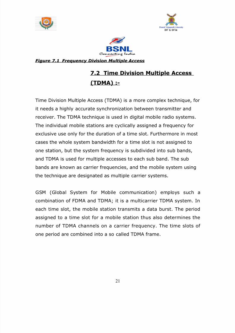
8142019 Dipti Report
httpslidepdfcomreaderfulldipti-report 2162
Figure 71 Frequency Division Multiple Access
72 Time Division Multiple Access
(TDMA) -
Time Division Multiple Access (TDMA) is a more complex technique for
it needs a highly accurate synchronization between transmitter and
receiver The TDMA technique is used in digital mobile radio systems
The individual mobile stations are cyclically assigned a frequency for
exclusive use only for the duration of a time slot Furthermore in most
cases the whole system bandwidth for a time slot is not assigned to
one station but the system frequency is subdivided into sub bands
and TDMA is used for multiple accesses to each sub band The sub
bands are known as carrier frequencies and the mobile system using
the technique are designated as multiple carrier systems
GSM (Global System for Mobile communication) employs such a
combination of FDMA and TDMA it is a multicarrier TDMA system In
each time slot the mobile station transmits a data burst The period
assigned to a time slot for a mobile station thus also determines the
number of TDMA channels on a carrier frequency The time slots of
one period are combined into a so called TDMA frame
21
8142019 Dipti Report
httpslidepdfcomreaderfulldipti-report 2262
Figure72 Time Division Multiple Access
721 The Advantages of TDMA are -
1 Permits flexible bit rates (ie multiple time slots can be
assigned to a user eg if each time slot translates to 32Kbps
then a 64Kbps user gets assigned 2 slots per frame)
2 Can support bursts or variable bit rate traffic Number of slots
assigned to a user can be changed frame by frame (eg 2 slots
in frame 1 3 slots in frame 2 1 slot in frame 3 0 slots in frame
4 etc)
3 No guard bands required for wideband system
4 No narrowband filters required for wideband system
722 The Disadvantages of TDMA are -
22
8142019 Dipti Report
httpslidepdfcomreaderfulldipti-report 2362
1 The high bit rates of wideband systems require complex
equalization
2 Because of burst mode of operation a large number of overhead
bits for synchronization and framing are required
3 Guard time is required in each slot to accommodate time
inaccuracies because of clock instability
4 Electronics operating at high bit rates increase power
consumption
5 Complex signal processing is required for synchronize within a
short slot time
Figure 73 Combination of TDMA and FDMA
73 Code Division Multiple Access
(CDMA) -
Code Division Multiple Access system is very different from time and
frequency division multiplexing In this system a particular user has
23
8142019 Dipti Report
httpslidepdfcomreaderfulldipti-report 2462
access to the entire bandwidth for the entire time duration The basic
principle of CDMA is that different codes are used to distinguish
between the different users Typically used forms of modulation are
Direct Sequence spread spectrum (DS-CDMA) frequency hopping or
Joint Detection CDMA (JDCDMA) Here a signal is generated that
spreads out over a wide bandwidth A code known as a spreading code
is used to perform this action By using a group of codes which are
orthogonal to each other it is possible to pick out a signal with a given
code in the presence of many other signals with different orthogonal
codes In fact many different baseband signals with 6 different
spreading codes can be modulated onto the same carrier to enable
many different users to be supported By using different orthogonal
codes interference between the signals is minimal Conversely when
signals are received from several mobile stations the base station is
able to isolate each one as they have different orthogonal spreading
codes
CDMA has a-Spectrum of-4507008009001700180019002100
MHz
Channel Bandwidth of 125 MHz
731 The Advantages of CDMA are -
1 CDMA has a soft capacity The more the number of codes more
the number of users
24
8142019 Dipti Report
httpslidepdfcomreaderfulldipti-report 2562
2 CDMA requires tight power control as it suffers for far-near
effect In other words a user close to the base station
transmitting with the same power as a user farther away will
drown the latterrsquos signal All signals must have more or less
equal power at the receiver
3 Rake receivers can be used to improve signal reception Time
delayed versions (a chip or more delayed) of the signal(multipath signals) can be collected and used to make bit level
decisions
4 Mobiles can switch base stations without switching carriers Two
base stations receive the mobile signal and the mobile is
receiving from two base stations
732 The Disadvantages of CDMA are -
1 The code length has to be carefully selected A large code length
can induce delay or even cause interference
2 Time synchronization is necessary
3 Soft handoff increases use of radio resources and hence can
reduce capacity
4 As the sum of the power received at and transmitted from a
base station has to constant a tight power control is needed
This can result in more handoffs
25
8142019 Dipti Report
httpslidepdfcomreaderfulldipti-report 2662
Figure 74 Code Division Multiple Access
74 Leased line
To transmit data between computer and electronic information
devices BSNL provides data communication services to its
subscribers It offers a choice of high medium and low speed leased
data circuits as well as dial-up lines Bandwidth is available on
demand in most of the cities Managed leased Line Network (MLLN)
offers flexibility of providing circuits with speeds of n x 64 Kbps up to
2 Mbps
Leased circuits are provided to subscribers for internal communication
between their officesfactories at various sites within a citytown or
different citiestown on point to point basis or on a network basis
interconnecting the various sites
26
8142019 Dipti Report
httpslidepdfcomreaderfulldipti-report 2762
741 Services provided by leased line -
1 Speech circuits
2 Data circuits
a Point to point data circuit
b Private data network
c Closed user group
3 Telegraph and tele ndash printer circuits
4 International leased circuit
742 Managed Leased Line Service (MLLN)
The MLLN is a Managed Leased Line Network system which is proposed
to provide Leased line connectivity The State-of-the-art technology
equipment MLLN is designed mainly for having effective control
monitor on the leased line so that the down time is very much
minimized
27
8142019 Dipti Report
httpslidepdfcomreaderfulldipti-report 2862
CHAPTER 8
INTRODUCTION
BROADBAND
The Broadband service is based on DSL technology (on the same
copper cable that is used for connecting telephone) countrywide
spanning 198 cities BSNL has commissioned a world class multi-
gigabit multi-protocol convergent IP infrastructure through National
Internet Backbone-II (NIB-II)
The services includes always-on broadband access to the Internet for
residential and business customers Content based services Video
multicasting Video-on-demand and Interactive gaming Audio and
Video conferencing IP Telephony Distance learning Messaging plain
and feature rich Multi-site MPLS VPNs with Quality of Service (QoS)
guarantees The subscriber accesses the above services through
Subscriber Service Selection System (SSSS) portal
28
8142019 Dipti Report
httpslidepdfcomreaderfulldipti-report 2962
BROADBAND is a form of internet service The only difference
between broadband and internet is the speed We receive broadband
and caller facility on the same copper wire with the help of a
SPLITTER which is a kind of low pass filter which separates a normal
call from the broadband data BSNL provides a staggering speed of 2
MBPS which is the fastest in India
Since we require less uploading compared to downloading so
broadband provides higher bandwidth and speed for downlink as
compared to uplink to suit our necessity Since the uplink and
downlink speed and bandwidth is different so a process called ADSL is
used
ADSL stands for Asymmetric Digital Subscriber Line It is a technology
that allows copper telephone pairs to be used to provide a broadband
connection It provides lsquoalways-onrsquo Internet connection that is
automatically established once the PC and ADSL modem are switched
on and instant log-in procedure is completed
lsquoAlways-Onrsquo means that the broadband sets up a permanent
connection to the Internet that lets you access the Internet as soon as
you switch on the computer and the CPE and do an instant log-in with
your user name and password There will be no separate Internet
telephone call charges
81 Benefits of ADSL
bull Fast downloads
bull At least 45 times and upto 35 times faster than dial-up
29
8142019 Dipti Report
httpslidepdfcomreaderfulldipti-report 3062
connection
bull Always on connection
bull Telephone and Internet access can be used together
bull No telephone call charges for internet surfing
bull Cost effective way to access Internet
bull A host of free content on the web can be downloaded faster
82 Main Objectives of Broadband are -
bull To provide high speed Internet connectivity (upto 8 Mbps)
bull To provide Virtual Private Network (VPN) service to the
broadband customers
bull To provide dial VPN service to MPLS VPN customers
bull To provide multicast video services video-on-demand etc
through the Broadband Remote Access Server (BRAS)
bull To provide a means to bill for the aforesaid services by either
time-based or volume-based billing It shall provide the
customer with the option to select the services through web
server
bull To provide both pre-paid and post paid broadband services
83 Services available through Broadband -
bull High speed Internet Access This is the always-on
Internet access service with speed ranging from 256 kbps to 8
Mbps
30
8142019 Dipti Report
httpslidepdfcomreaderfulldipti-report 3162
bull Bandwidth on Demand This facilitates customer to
change bandwidth as per his her requirement For example a
customer with 256 kbps can change to 1 Mbps during the video
Conferencing session
bull Multicasting This provides video multicast services for
application in distance education telemedicine etc
bull Dial VPN Service This service allows remote users to
access their private network securely over the NIB-II
infrastructure
bull Video and Audio Conferencing
bull Content based Services Like Video on Demand
Interactive Gaming Live and time shifted TV
31
8142019 Dipti Report
httpslidepdfcomreaderfulldipti-report 3262
Figure 81 Front Screen for Broadband Connection
CHAPTER 9
INTRODUCTION
32
8142019 Dipti Report
httpslidepdfcomreaderfulldipti-report 3362
GSM
GSM (Global System for Mobile communications) is an open digital
cellular technology used for transmitting mobile voice and data
services GSM differs from first generation wireless systems in that it
uses digital technology and time division multiple access transmission
methods
GSM is a circuit-switched system that divides each 200 kHz channel
into eight 25 kHz time-slots GSM operates in the 900MHz and 18GHz
bands in Europe and the 19GHz and 850MHz bands in the US The
850MHz band is also used for GSM and 3GSM in Australia Canada and
many South American countries
GSM supports data transfer speeds of up to 96 kbits allowing the
transmission of basic data services such as SMS (Short Message
Service) Another major benefit is its international roaming capability
allowing users to access the same services when travelling abroad as
at home This gives consumers seamless and same number
connectivity in more than 210 countries GSM satellite roaming has
also extended service access to areas where terrestrial coverage is not
available
91 GSM Interfaces -
33
8142019 Dipti Report
httpslidepdfcomreaderfulldipti-report 3462
II A - Interface
This is the interface within the GSM network architecture between the
BSS (Base Station Subsystem) and an MSC (Mobile Switching Centre)
The interface supports standard 64Kbps channels for signalling and
traffic The primary protocols on this interface are DTAP (Direct
Transfer Application Part) and BSSMAP (Base Station Subsystem
Management Application Part)
Figure 91 A - Interface
III Abis ndash Interface
The interface within the GSM architecture between the BTS (Base Transceiver
Station) and BSC (Base Station Controller) This interface is usually configured
using a 16Kbps slot structure
34
8142019 Dipti Report
httpslidepdfcomreaderfulldipti-report 3562
Figure 92 Abis Interface
Air ndash Interface (UM Interface)Interface between MS to BTS
B ndash Interface
Interface between MSC to VLR
C- Interface
Interface between HLR to MSC
D-Interface
Interface between HLR to VLR
35
8142019 Dipti Report
httpslidepdfcomreaderfulldipti-report 3662
E-Interface
Interface between MSC to MSC
F-Interface
Interface between MSC to EIR
G-InterfaceInterface between VLR to VLR
H-Interface
Interface between HLR to AUC
Figure 93 Mobile Tower having Antenna
36
8142019 Dipti Report
httpslidepdfcomreaderfulldipti-report 3762
Figure 94 GSM Architecture along with Interfaces
92 Architecture of the GSM network
The GSM network can be divided into four main parts
bull The Mobile Station (MS)
bull The Base Station Subsystem (BSS)
bull The Network and Switching Subsystem (NSS)
bull The Operation and Support Subsystem (OSS)
921 Mobile Station
A Mobile Station consists of two main elements
37
8142019 Dipti Report
httpslidepdfcomreaderfulldipti-report 3862
bull The mobile equipment or terminal
bull The Subscriber Identity Module (SIM)
Figure 95 Mobile Equipment and SIM
The Terminal
There are different types of terminals distinguished principally by their
power and application
bull The `fixed terminals are the ones installed in cars Their
maximum allowed output power is 20 W
bull The GSM portable terminals can also be installed in vehicles
Their maximum allowed output power is 8W
bull The handhels terminals have experienced the biggest success
thanks to thei weight and volume which are continuously
decreasing These terminals can emit up to 2 W The evolution of
technologies allows to decrease the maximum allowed power to
08 W
38
8142019 Dipti Report
httpslidepdfcomreaderfulldipti-report 3962
The SIM
The SIM is a smart card that identifies the terminal By inserting the
SIM card into the terminal the user can have access to all the
subscribed services Without the SIM card the terminal is not
operational
Another advantage of the SIM card is the mobility of the users In fact
the only element that personalizes a terminal is the SIM card
922 The Base Station Subsystem
The BSS connects the Mobile Station and the NSS It is in charge of
the transmission and reception The BSS can be divided into two parts
bull The Base Transceiver Station (BTS) or Base Station
bull The Base Station Controller (BSC)
9221 The Base Transceiver Station
The BTS corresponds to the transceivers and antennas used in
each cell of the network A BTS is usually placed in the center of a cell
Its transmitting power defines the size of a cell Each BTS has between
one and sixteen transceivers depending on the density of users in the
cell
39
8142019 Dipti Report
httpslidepdfcomreaderfulldipti-report 4062
40
8142019 Dipti Report
httpslidepdfcomreaderfulldipti-report 4162
Figure96 Picture of BTS
9222 The Base Station Controller
The BSC controls a group of BTS and manages their radio ressources
A BSC is principally in charge of handovers frequency hopping
exchange functions and control of the radio frequency power levels of
the BTSs
41
8142019 Dipti Report
httpslidepdfcomreaderfulldipti-report 4262
Figure 97 Picture of BSC
42
8142019 Dipti Report
httpslidepdfcomreaderfulldipti-report 4362
923 The Network and Switching Subsystem
Its main role is to manage the communications between the mobile
users and other users such as mobile users ISDN users fixed
telephony users etc It also includes data bases needed in order to
store information about the subscribers and to manage their mobility
The different components of the NSS are described below
92 31 The Mobile services Switching Center (MSC)
It is the central component of the NSS The MSC
performs the switching functions of the network It also provides
connection to other networks
9232 The Gateway Mobile services Switching Center
(GMSC)
A gateway is a node interconnecting two networks The GMSC is the
interface between the mobile cellular network and the PSTN It is in
charge of routing calls from the fixed network towards a GSM user
The GMSC is often implemented in the same machines as the MSC
92 33 Home location register (HLR)
HLR stores information of subscriber belonging to the covering area of
MSC It also stores the current location of these subscribers and the
service to which they have access
43
8142019 Dipti Report
httpslidepdfcomreaderfulldipti-report 4462
9234 Visitor location register (VLR)
VLR contains information from subscriberrsquos HLR necessary in order to
provide the subscribed services to visiting users
VLR is always implemented together with a MSC soothe area under
control of the MSC is also the area under control of the VLR
9235 Authentication center (AUC)
AUC register is used for security purpose It helps to verify the userrsquos
identity
9236 Equipment identity register (EIR )
EIR contains a list of all valid terminals The EIR allows the forbid calls
from stolen or unauthorized terminals
92 37 The GSM Interworking Unit (GIWU)
The GIWU corresponds to an interface to various networks for data
communications During these communications the transmission of
speech and data can be alternated
924 The Operation and Support Subsystem (OSS)
The OSS is connected to the different components of the NSS and to
the BSC in order to control and monitor the GSM system It is also in
charge of controlling the traffic load of the BSS
44
8142019 Dipti Report
httpslidepdfcomreaderfulldipti-report 4562
Figure 98 BLOCK DIAGRAM OF MOBILE TOWER AND
TRANSMISSION
93 The GSM functions
In this paragraph the description of the GSM network is focused on
the differents functions to fulfil by the network and not on its physical
components In GSM five main functions can be defined
bull Transmission
bull Radio Resources management (RR)
bull Mobility Management (MM)
bull Communication Management (CM)
bull Operation Administration and Maintenance (OAM)
45
8142019 Dipti Report
httpslidepdfcomreaderfulldipti-report 4662
94 GSM Frequencies
In principle the GSM system can be implemented in any frequency
band However there are several bands where GSM terminals are or
will shortly be available Furthermore GSM terminals may incorporate
one or more of the GSM frequency bands listed below to facilitate
roaming on a global basis
Frequency Range
GSM400 4504 - 4576 MHz paired with 4604 - 4676
MHz
or
4788 - 486 MHz paired with 4888 - 496 MHz
GSM 850 824 - 849 MHz paired with 869 - 894 MHz
GSM900 880 - 915 MHz paired with 925 - 960 MHz
GSM1800 1710 - 1785 MHz paired with 1805 - 1880 MHz
GSM1900 1850 - 1910 MHz paired with 1930 - 1990 MHz
95 Frequency allocation
Two frequency bands of 25 Mhz each one have been allocated for the
GSM system
bull The band 890-915 Mhz has been allocated for the uplink
direction (transmitting from the mobile station to the base
station)
46
8142019 Dipti Report
httpslidepdfcomreaderfulldipti-report 4762
bull The band 935-960 Mhz has been allocated for the downlink
direction (transmitting from the base station to the mobile
station)
But not all the countries can use the whole GSM frequency bands
This is due principally to military reasons and to the existence of
previous analog systems using part of the two 25 Mhz frequency
bands
Traffic is measured in ERLANG
BSC Capacity is 1min 5000 ERLANG
Now in 3G in respect of BSC MSC
RNC(Radio Network Control) is used
CHAPTER 10
47
8142019 Dipti Report
httpslidepdfcomreaderfulldipti-report 4862
INTRODUCTION
MAIN DISTRIBUTION FRAME (MDF)
The main distribution frame acts as a link between the
exchange indoor and the exchange outdoor It not only
connects the exchange with the subscriber but also protects
the exchange from environmental hazards such as lightning
strike
There are two sides in a MDF -
101 Line side - The line side belongs to the outdoor The
subscriber is connected to the exchange via the MDF In the
line side there are analog connections
This side of the exchange consists of verticals Each vertical
has 100 trans and receive pairs connected to it ie 100
subscribers are connected to the exchange via one vertical
Each vertical corresponds to a particular pillar The line wires
emanating from the verticals are connected to a cabinet
from where it is taken to a pillar which then is connected to
48
8142019 Dipti Report
httpslidepdfcomreaderfulldipti-report 4962
a distribution pole (DP) From here the lines are distributed
to the subscribers
For line testing on the line side the dial tone is tested on the
vertical first If it is found to be ok then the testing is carried
forward to the cabinet From here line wires are carried
forward in a cluster of around 100 pairs to the pillar A pillar
is usually located in the central part of an area where the
pillar is established so that distribution is convenient and
less expensive One distribution pole is set up to provide
connection to around 15 to 20 homes From here the
subscribers are directly connected
102 Exchange side - Exchange side belongs to the
exchange On the exchange side of the MDF the connections
are DigitalThe connection between the
exchange and the subscriber is made in various stages On
the exchange side the MDF is directly connected to the DLU
in the SN (Switching Network) In the MDF the two sides
49
8142019 Dipti Report
httpslidepdfcomreaderfulldipti-report 5062
are connected through a jumper wire The line testing for
the exchange is done first here using a dial tone checker
For rectifying errors each subscriber is assigned an
Equipment Number (NE) This number is the identification
mark of the subscriber for the exchange It represents the
location in the DLU from where the connection is provided
The DLU is then connected to the LTG (Line Trunk Groups)
from here the switching network is connected
CHAPTER 11
50
8142019 Dipti Report
httpslidepdfcomreaderfulldipti-report 5162
INTRODUCTION
THE POWER PLANT
Power Plant is the main part of an Exchange It provide uninterrupted
power to the exchange continuously it also plays the role of converting
AC power to DC power
The arrangement made has one active and two standby systems for
supplying power This makes the system extremely reliable even in the
areas with acute power shortage Options like maintenance free
batteries (VRLA) also make it cost effective
There are three supply options in the power plant
bull The AC mains
bull The Value Regulated Lead Acid battery set
bull The engine alternator
111 The AC Mains
The exchange requires a constant supply voltage of 48V (DC) in the
running condition So the voltage obtained from which is 66 KV needs
51
8142019 Dipti Report
httpslidepdfcomreaderfulldipti-report 5262
to be stepped down and rectified to DC voltage This function is
performed by the float rectifier unit
112 The Battery Set
There are two sets of VRLA batteries which are maintenance free
batteries Each set is capable of providing the required 48V DC supply
and have a capacity of 4000 AH (Ampere Hour) They are named as
set A and set B One set is active while the other set is available for
standby In case AC mains power is on both the sets of batteries get
charged As soon as there is a power cut the load gets switched over
to the battery set and one of the sets gets active while the other is
available for standby But even this source cannot be trusted for very
long durations as each set is capable of sustaining the load only for
about 3 hours So we need another alternative to provide a fool proof
system This calls for the use of the engine alternator
1113 The Engine Alternator
Usually the battery set is always kept for standby operation In case
there is a power cut the battery set operates hardly for 5 to 10
minutes which is the time taken for the alternator to start
There are also two sets of generators which are rated as follows
bull 66 KV415V voltage rating with moisture absorber
bull 200 KVA power rating
52
8142019 Dipti Report
httpslidepdfcomreaderfulldipti-report 5362
CHAPTER 12
INTRODUCTION
OPERATION AND MAINTENANCE TERMINAL
On the basis of Operation and maintenance terminal Function it has
been grouped into following categories
121 OPERATING FUNCTIONS
1 Charging function
2 Continuous connectivity management
3 Memory management of Translator
122 SUPERVISION FUNCTIONS
1 Circuit tests
2 Line and subscriber set tests
3 Load and traffic observation
123 MAINTENANCE FUNCTIONS
1 Maintenance of exchange control unit memories
2 Fault location and trouble-shooting aid function
3 Telephone equipment position
53
8142019 Dipti Report
httpslidepdfcomreaderfulldipti-report 5462
CHAPTER 13
INTRODUCTION
PULSE CODE MODULATION
PCM is a process which converts a continuous analog signal into digital
signals It is a Multichannel transmission technique that explores the
advantage of digital transmission over analog transmission It only
realizes the advantages of improved transmission limits greater noise
immunity lesser distortion of dial pulses but also economy
Converting continuous analog signal into digital signals is
carried out in three stages-
131 Sampling- Sampling is a periodical
measurement of the value of the analog signal A sampled
data contains all the information of the signal if the
sampling frequency is at least twice the highest frequency
of the signal to be sampled As the signals in telephony are
band limited to 300-3400Hz a sampling are frequency of
8000Hz ie every 125 micro seconds is sufficient
54
8142019 Dipti Report
httpslidepdfcomreaderfulldipti-report 5562
132 Quantizing - representation of their amplitude is forced to
take certain value To ensure that the ratio between signal amplitude
and errors introduced by quantized and encoded (companding) law is
applied
133 Encoding - PAM signals are quantized and encoded into 8
bit symmetrical binary code and transmitted on line during the time
slot allotted to that channel as PCM signals
At the receive side these PCM signals are decoded into PAM
signals and smoothed out by passing through low-pass filters to filters
to get back originals signals
This PCM system can support 30 simultaneous telephone conversation
and optionally 8 telegraphteleprinter channels on one line Individual
channels have a transmission speed of 64 Kbitss and the total
transmission rate for all 32 channels in the system is 2048 Kbitss
55
8142019 Dipti Report
httpslidepdfcomreaderfulldipti-report 5662
CHAPTER 14
INTRODUCTION
SWITCHING
There are two types of switching namely CIRCUIT Switching and
PACKET Switching
141 CIRCUIT SWITCHING - A circuit switching network is onethat establishes a dedicated circuit between nodes and terminals
before the users may communicate Each circuit that is dedicated
cannot be used by other callers until the circuit is released and a new
connection is set up Even if no actual communication is taking place in
a dedicated circuit then that channel still remains unavailable to other
users Channels that are available for new calls to be set up are said to
be idle Early telephone exchanges are a suitable example of circuitswitching
142 PACKET SWITCHING - Packet switching is a
communications paradigm in which packets are routed between nodes
over data links shared with other traffic This contrasts with the other
56
8142019 Dipti Report
httpslidepdfcomreaderfulldipti-report 5762
principal paradigm circuit switching which sets up a dedicated
connection between the two nodes for their exclusive use for the
duration of the communication Packet switching is used to optimize
the use of the channel capacity available in a network to minimize the
transmission latency (ie the time it takes for data to pass across the
network) and to increase robustness of communication
143 Circuit Switching vs Packet
Switching
In principle circuit switching and packet switching both are used in
high-capacity networks In circuit-switched networks network
resources are static set in ldquocopperrdquo if you will from the sender to
receiver before the start of the transfer thus creating a ldquocircuitrdquo The
resources remain dedicated to the circuit during the entire transfer and
the entire message follows the same path In packet-switched
networks the message is broken into packets each of which can take
a different route to the destination where the packets are recompiled
into the original message Circuit switching contrasts with packet
switching which splits traffic data (for instance digital representation
of sound or computer data) into chunks called packets that are
routed over a shared network Packet switching networks do not
require a circuit to be established and allow many pairs of nodes to
communicate almost simultaneously over the same channel Each
57
8142019 Dipti Report
httpslidepdfcomreaderfulldipti-report 5862
packet is individually addressed precluding the need for a dedicated
path to help the packet find its way to its destination
CHAPTER 15
CONCLUSION
This Practical Training has given me an opportunity to know about various
technologies working behind in todayrsquos advanced world of telecommunication
All those that we read in our Book only theoretically by this training I observe all
those practically I come across different units in telecom exchange like
E10BOCBEWSD Mobile (GSM) BSC and BTS MDF and Power Plant
and Broadband I not only watch those equipment but also know about those
there working there functions and also how by work to provide us facility of
telecomI am very grateful to those persons who helped directly amp
indirectly in the successful completion of this practical training and this will
surely be fruitful in future
58
8142019 Dipti Report
httpslidepdfcomreaderfulldipti-report 5962
CHAPTER 16
APPENDIX
161 Loading statement of Jamshedpur OCB-283Capacity of the TAXndash22K Loading ndash 5915
Station IC OG Between Total PCM
Arra Nil Nil 30 1
Ambala Nil Nil 30 1
Bangalore Nil Nil 61 2
Bhagalpur Nil Nil 60 2
Chennai Nil Nil 30 1
Cuttack Nil Nil 184 6
Daltengung Nil Nil 30 1
Darbhanga Nil Nil 60 2
Delhi bsnl Nil Nil 122 4Delhi mtnl Nil Nil 91 3
Dhanbad Nil Nil 122 4
Dumka Nil Nil 30 1
Ericson1 Nil Nil 494 16
Ericson2 Ni Nil 122 4
Gaya Nil Nil 61 2
Hajipur Nil Nil 30 1
Hazaribag Nil Nil 91 3
Hyderabad Nil Nil 123 4
Kolkata Nil Nil 246 8
Kharagpur Nil Nil 91 3
Katihar Nil Nil 30 1
Lucknow Nil Nil 90 3
Mumbai bsnl Nil Nil 61 2
Mumbai mtnl Nil Nil 62 2
59
8142019 Dipti Report
httpslidepdfcomreaderfulldipti-report 6062
Munger Nil Nil 30 1
Muzafferpur Nil Nil 61 2
Nortel Nil Nil 587 19
Purulia Nil Nil 61 2
Patna Nil Nil 151 5
Patliputr Nil Nil 122 8
Raurkela Nil Nil 91 3
Ranchi 15 45 680 24
Sasaram Nil Nil 30 1
Saharsa Nil Nil 30 1Sakla Nil Nil 153 5
Sambalpur Nil Nil 30 1
Tarang Nil Nil 154 5
Baripada Nil Nil 60 2
MSCA Nil Nil 309 10
Msc bokaro Nil Nil 618 20
Total 15 45 5518 182
162 OCB ndash 283 MAIN TELEPHONE EXCHANGES
EXCHANGE CAPACITY PCM
Main Exchange 12k -
Rsu Telco 11256 15
Rsu Adityapur 3k -
Rsu Sidhgora 4k 12
Rsu Mani fit 4256k 11
Rsu Govindpur 2k 10
Rsu Tatanagar 4256k 14
Rsu Parsudih 4k 11
Dlcjsr 6rt -Dlc Parsudih 2rt -
DlcTelco 1rt -
RsuKharkai 1k -
Ghatsila 6585 12
Bahragora 6594 3
Chaibasa 6582 12
60
8142019 Dipti Report
httpslidepdfcomreaderfulldipti-report 6162
Chakardharpur 6587 5
Manoharpur 6593 2
Saraikela 6597 7
Chandil 6591 -
Jhinkpani 6589 -
Jagannathpur 6588 -
Giriburu 6596 4
Nowamundi 6596 5
Kharzwara 6583 -
163 PHONE CODES AND THEIR EXCHANGE CODE
61
PHONE CODE EXCHANGE
2758 JSR
2756 JSR
2421 JSR
243 JSR
244 JSR
248 JSR
222 JSR223 JSR
265 SNK
240 ADR
220 ADR
2370-3 ADR
2380-3 ADR
2386-87 GMR
246 amp 236 MNG
29 7 DIGIT WJSR
2270 GVP2277 GVP
2290-95 TAT
2296 PSD
230-231 KDM
234 GOL
226228 TLC
221 SDG
232 LIC
2249 KHL
8142019 Dipti Report
httpslidepdfcomreaderfulldipti-report 6262
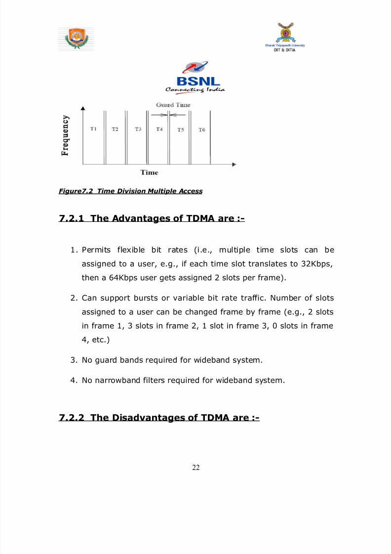
8142019 Dipti Report
httpslidepdfcomreaderfulldipti-report 2262
Figure72 Time Division Multiple Access
721 The Advantages of TDMA are -
1 Permits flexible bit rates (ie multiple time slots can be
assigned to a user eg if each time slot translates to 32Kbps
then a 64Kbps user gets assigned 2 slots per frame)
2 Can support bursts or variable bit rate traffic Number of slots
assigned to a user can be changed frame by frame (eg 2 slots
in frame 1 3 slots in frame 2 1 slot in frame 3 0 slots in frame
4 etc)
3 No guard bands required for wideband system
4 No narrowband filters required for wideband system
722 The Disadvantages of TDMA are -
22
8142019 Dipti Report
httpslidepdfcomreaderfulldipti-report 2362
1 The high bit rates of wideband systems require complex
equalization
2 Because of burst mode of operation a large number of overhead
bits for synchronization and framing are required
3 Guard time is required in each slot to accommodate time
inaccuracies because of clock instability
4 Electronics operating at high bit rates increase power
consumption
5 Complex signal processing is required for synchronize within a
short slot time
Figure 73 Combination of TDMA and FDMA
73 Code Division Multiple Access
(CDMA) -
Code Division Multiple Access system is very different from time and
frequency division multiplexing In this system a particular user has
23
8142019 Dipti Report
httpslidepdfcomreaderfulldipti-report 2462
access to the entire bandwidth for the entire time duration The basic
principle of CDMA is that different codes are used to distinguish
between the different users Typically used forms of modulation are
Direct Sequence spread spectrum (DS-CDMA) frequency hopping or
Joint Detection CDMA (JDCDMA) Here a signal is generated that
spreads out over a wide bandwidth A code known as a spreading code
is used to perform this action By using a group of codes which are
orthogonal to each other it is possible to pick out a signal with a given
code in the presence of many other signals with different orthogonal
codes In fact many different baseband signals with 6 different
spreading codes can be modulated onto the same carrier to enable
many different users to be supported By using different orthogonal
codes interference between the signals is minimal Conversely when
signals are received from several mobile stations the base station is
able to isolate each one as they have different orthogonal spreading
codes
CDMA has a-Spectrum of-4507008009001700180019002100
MHz
Channel Bandwidth of 125 MHz
731 The Advantages of CDMA are -
1 CDMA has a soft capacity The more the number of codes more
the number of users
24
8142019 Dipti Report
httpslidepdfcomreaderfulldipti-report 2562
2 CDMA requires tight power control as it suffers for far-near
effect In other words a user close to the base station
transmitting with the same power as a user farther away will
drown the latterrsquos signal All signals must have more or less
equal power at the receiver
3 Rake receivers can be used to improve signal reception Time
delayed versions (a chip or more delayed) of the signal(multipath signals) can be collected and used to make bit level
decisions
4 Mobiles can switch base stations without switching carriers Two
base stations receive the mobile signal and the mobile is
receiving from two base stations
732 The Disadvantages of CDMA are -
1 The code length has to be carefully selected A large code length
can induce delay or even cause interference
2 Time synchronization is necessary
3 Soft handoff increases use of radio resources and hence can
reduce capacity
4 As the sum of the power received at and transmitted from a
base station has to constant a tight power control is needed
This can result in more handoffs
25
8142019 Dipti Report
httpslidepdfcomreaderfulldipti-report 2662
Figure 74 Code Division Multiple Access
74 Leased line
To transmit data between computer and electronic information
devices BSNL provides data communication services to its
subscribers It offers a choice of high medium and low speed leased
data circuits as well as dial-up lines Bandwidth is available on
demand in most of the cities Managed leased Line Network (MLLN)
offers flexibility of providing circuits with speeds of n x 64 Kbps up to
2 Mbps
Leased circuits are provided to subscribers for internal communication
between their officesfactories at various sites within a citytown or
different citiestown on point to point basis or on a network basis
interconnecting the various sites
26
8142019 Dipti Report
httpslidepdfcomreaderfulldipti-report 2762
741 Services provided by leased line -
1 Speech circuits
2 Data circuits
a Point to point data circuit
b Private data network
c Closed user group
3 Telegraph and tele ndash printer circuits
4 International leased circuit
742 Managed Leased Line Service (MLLN)
The MLLN is a Managed Leased Line Network system which is proposed
to provide Leased line connectivity The State-of-the-art technology
equipment MLLN is designed mainly for having effective control
monitor on the leased line so that the down time is very much
minimized
27
8142019 Dipti Report
httpslidepdfcomreaderfulldipti-report 2862
CHAPTER 8
INTRODUCTION
BROADBAND
The Broadband service is based on DSL technology (on the same
copper cable that is used for connecting telephone) countrywide
spanning 198 cities BSNL has commissioned a world class multi-
gigabit multi-protocol convergent IP infrastructure through National
Internet Backbone-II (NIB-II)
The services includes always-on broadband access to the Internet for
residential and business customers Content based services Video
multicasting Video-on-demand and Interactive gaming Audio and
Video conferencing IP Telephony Distance learning Messaging plain
and feature rich Multi-site MPLS VPNs with Quality of Service (QoS)
guarantees The subscriber accesses the above services through
Subscriber Service Selection System (SSSS) portal
28
8142019 Dipti Report
httpslidepdfcomreaderfulldipti-report 2962
BROADBAND is a form of internet service The only difference
between broadband and internet is the speed We receive broadband
and caller facility on the same copper wire with the help of a
SPLITTER which is a kind of low pass filter which separates a normal
call from the broadband data BSNL provides a staggering speed of 2
MBPS which is the fastest in India
Since we require less uploading compared to downloading so
broadband provides higher bandwidth and speed for downlink as
compared to uplink to suit our necessity Since the uplink and
downlink speed and bandwidth is different so a process called ADSL is
used
ADSL stands for Asymmetric Digital Subscriber Line It is a technology
that allows copper telephone pairs to be used to provide a broadband
connection It provides lsquoalways-onrsquo Internet connection that is
automatically established once the PC and ADSL modem are switched
on and instant log-in procedure is completed
lsquoAlways-Onrsquo means that the broadband sets up a permanent
connection to the Internet that lets you access the Internet as soon as
you switch on the computer and the CPE and do an instant log-in with
your user name and password There will be no separate Internet
telephone call charges
81 Benefits of ADSL
bull Fast downloads
bull At least 45 times and upto 35 times faster than dial-up
29
8142019 Dipti Report
httpslidepdfcomreaderfulldipti-report 3062
connection
bull Always on connection
bull Telephone and Internet access can be used together
bull No telephone call charges for internet surfing
bull Cost effective way to access Internet
bull A host of free content on the web can be downloaded faster
82 Main Objectives of Broadband are -
bull To provide high speed Internet connectivity (upto 8 Mbps)
bull To provide Virtual Private Network (VPN) service to the
broadband customers
bull To provide dial VPN service to MPLS VPN customers
bull To provide multicast video services video-on-demand etc
through the Broadband Remote Access Server (BRAS)
bull To provide a means to bill for the aforesaid services by either
time-based or volume-based billing It shall provide the
customer with the option to select the services through web
server
bull To provide both pre-paid and post paid broadband services
83 Services available through Broadband -
bull High speed Internet Access This is the always-on
Internet access service with speed ranging from 256 kbps to 8
Mbps
30
8142019 Dipti Report
httpslidepdfcomreaderfulldipti-report 3162
bull Bandwidth on Demand This facilitates customer to
change bandwidth as per his her requirement For example a
customer with 256 kbps can change to 1 Mbps during the video
Conferencing session
bull Multicasting This provides video multicast services for
application in distance education telemedicine etc
bull Dial VPN Service This service allows remote users to
access their private network securely over the NIB-II
infrastructure
bull Video and Audio Conferencing
bull Content based Services Like Video on Demand
Interactive Gaming Live and time shifted TV
31
8142019 Dipti Report
httpslidepdfcomreaderfulldipti-report 3262
Figure 81 Front Screen for Broadband Connection
CHAPTER 9
INTRODUCTION
32
8142019 Dipti Report
httpslidepdfcomreaderfulldipti-report 3362
GSM
GSM (Global System for Mobile communications) is an open digital
cellular technology used for transmitting mobile voice and data
services GSM differs from first generation wireless systems in that it
uses digital technology and time division multiple access transmission
methods
GSM is a circuit-switched system that divides each 200 kHz channel
into eight 25 kHz time-slots GSM operates in the 900MHz and 18GHz
bands in Europe and the 19GHz and 850MHz bands in the US The
850MHz band is also used for GSM and 3GSM in Australia Canada and
many South American countries
GSM supports data transfer speeds of up to 96 kbits allowing the
transmission of basic data services such as SMS (Short Message
Service) Another major benefit is its international roaming capability
allowing users to access the same services when travelling abroad as
at home This gives consumers seamless and same number
connectivity in more than 210 countries GSM satellite roaming has
also extended service access to areas where terrestrial coverage is not
available
91 GSM Interfaces -
33
8142019 Dipti Report
httpslidepdfcomreaderfulldipti-report 3462
II A - Interface
This is the interface within the GSM network architecture between the
BSS (Base Station Subsystem) and an MSC (Mobile Switching Centre)
The interface supports standard 64Kbps channels for signalling and
traffic The primary protocols on this interface are DTAP (Direct
Transfer Application Part) and BSSMAP (Base Station Subsystem
Management Application Part)
Figure 91 A - Interface
III Abis ndash Interface
The interface within the GSM architecture between the BTS (Base Transceiver
Station) and BSC (Base Station Controller) This interface is usually configured
using a 16Kbps slot structure
34
8142019 Dipti Report
httpslidepdfcomreaderfulldipti-report 3562
Figure 92 Abis Interface
Air ndash Interface (UM Interface)Interface between MS to BTS
B ndash Interface
Interface between MSC to VLR
C- Interface
Interface between HLR to MSC
D-Interface
Interface between HLR to VLR
35
8142019 Dipti Report
httpslidepdfcomreaderfulldipti-report 3662
E-Interface
Interface between MSC to MSC
F-Interface
Interface between MSC to EIR
G-InterfaceInterface between VLR to VLR
H-Interface
Interface between HLR to AUC
Figure 93 Mobile Tower having Antenna
36
8142019 Dipti Report
httpslidepdfcomreaderfulldipti-report 3762
Figure 94 GSM Architecture along with Interfaces
92 Architecture of the GSM network
The GSM network can be divided into four main parts
bull The Mobile Station (MS)
bull The Base Station Subsystem (BSS)
bull The Network and Switching Subsystem (NSS)
bull The Operation and Support Subsystem (OSS)
921 Mobile Station
A Mobile Station consists of two main elements
37
8142019 Dipti Report
httpslidepdfcomreaderfulldipti-report 3862
bull The mobile equipment or terminal
bull The Subscriber Identity Module (SIM)
Figure 95 Mobile Equipment and SIM
The Terminal
There are different types of terminals distinguished principally by their
power and application
bull The `fixed terminals are the ones installed in cars Their
maximum allowed output power is 20 W
bull The GSM portable terminals can also be installed in vehicles
Their maximum allowed output power is 8W
bull The handhels terminals have experienced the biggest success
thanks to thei weight and volume which are continuously
decreasing These terminals can emit up to 2 W The evolution of
technologies allows to decrease the maximum allowed power to
08 W
38
8142019 Dipti Report
httpslidepdfcomreaderfulldipti-report 3962
The SIM
The SIM is a smart card that identifies the terminal By inserting the
SIM card into the terminal the user can have access to all the
subscribed services Without the SIM card the terminal is not
operational
Another advantage of the SIM card is the mobility of the users In fact
the only element that personalizes a terminal is the SIM card
922 The Base Station Subsystem
The BSS connects the Mobile Station and the NSS It is in charge of
the transmission and reception The BSS can be divided into two parts
bull The Base Transceiver Station (BTS) or Base Station
bull The Base Station Controller (BSC)
9221 The Base Transceiver Station
The BTS corresponds to the transceivers and antennas used in
each cell of the network A BTS is usually placed in the center of a cell
Its transmitting power defines the size of a cell Each BTS has between
one and sixteen transceivers depending on the density of users in the
cell
39
8142019 Dipti Report
httpslidepdfcomreaderfulldipti-report 4062
40
8142019 Dipti Report
httpslidepdfcomreaderfulldipti-report 4162
Figure96 Picture of BTS
9222 The Base Station Controller
The BSC controls a group of BTS and manages their radio ressources
A BSC is principally in charge of handovers frequency hopping
exchange functions and control of the radio frequency power levels of
the BTSs
41
8142019 Dipti Report
httpslidepdfcomreaderfulldipti-report 4262
Figure 97 Picture of BSC
42
8142019 Dipti Report
httpslidepdfcomreaderfulldipti-report 4362
923 The Network and Switching Subsystem
Its main role is to manage the communications between the mobile
users and other users such as mobile users ISDN users fixed
telephony users etc It also includes data bases needed in order to
store information about the subscribers and to manage their mobility
The different components of the NSS are described below
92 31 The Mobile services Switching Center (MSC)
It is the central component of the NSS The MSC
performs the switching functions of the network It also provides
connection to other networks
9232 The Gateway Mobile services Switching Center
(GMSC)
A gateway is a node interconnecting two networks The GMSC is the
interface between the mobile cellular network and the PSTN It is in
charge of routing calls from the fixed network towards a GSM user
The GMSC is often implemented in the same machines as the MSC
92 33 Home location register (HLR)
HLR stores information of subscriber belonging to the covering area of
MSC It also stores the current location of these subscribers and the
service to which they have access
43
8142019 Dipti Report
httpslidepdfcomreaderfulldipti-report 4462
9234 Visitor location register (VLR)
VLR contains information from subscriberrsquos HLR necessary in order to
provide the subscribed services to visiting users
VLR is always implemented together with a MSC soothe area under
control of the MSC is also the area under control of the VLR
9235 Authentication center (AUC)
AUC register is used for security purpose It helps to verify the userrsquos
identity
9236 Equipment identity register (EIR )
EIR contains a list of all valid terminals The EIR allows the forbid calls
from stolen or unauthorized terminals
92 37 The GSM Interworking Unit (GIWU)
The GIWU corresponds to an interface to various networks for data
communications During these communications the transmission of
speech and data can be alternated
924 The Operation and Support Subsystem (OSS)
The OSS is connected to the different components of the NSS and to
the BSC in order to control and monitor the GSM system It is also in
charge of controlling the traffic load of the BSS
44
8142019 Dipti Report
httpslidepdfcomreaderfulldipti-report 4562
Figure 98 BLOCK DIAGRAM OF MOBILE TOWER AND
TRANSMISSION
93 The GSM functions
In this paragraph the description of the GSM network is focused on
the differents functions to fulfil by the network and not on its physical
components In GSM five main functions can be defined
bull Transmission
bull Radio Resources management (RR)
bull Mobility Management (MM)
bull Communication Management (CM)
bull Operation Administration and Maintenance (OAM)
45
8142019 Dipti Report
httpslidepdfcomreaderfulldipti-report 4662
94 GSM Frequencies
In principle the GSM system can be implemented in any frequency
band However there are several bands where GSM terminals are or
will shortly be available Furthermore GSM terminals may incorporate
one or more of the GSM frequency bands listed below to facilitate
roaming on a global basis
Frequency Range
GSM400 4504 - 4576 MHz paired with 4604 - 4676
MHz
or
4788 - 486 MHz paired with 4888 - 496 MHz
GSM 850 824 - 849 MHz paired with 869 - 894 MHz
GSM900 880 - 915 MHz paired with 925 - 960 MHz
GSM1800 1710 - 1785 MHz paired with 1805 - 1880 MHz
GSM1900 1850 - 1910 MHz paired with 1930 - 1990 MHz
95 Frequency allocation
Two frequency bands of 25 Mhz each one have been allocated for the
GSM system
bull The band 890-915 Mhz has been allocated for the uplink
direction (transmitting from the mobile station to the base
station)
46
8142019 Dipti Report
httpslidepdfcomreaderfulldipti-report 4762
bull The band 935-960 Mhz has been allocated for the downlink
direction (transmitting from the base station to the mobile
station)
But not all the countries can use the whole GSM frequency bands
This is due principally to military reasons and to the existence of
previous analog systems using part of the two 25 Mhz frequency
bands
Traffic is measured in ERLANG
BSC Capacity is 1min 5000 ERLANG
Now in 3G in respect of BSC MSC
RNC(Radio Network Control) is used
CHAPTER 10
47
8142019 Dipti Report
httpslidepdfcomreaderfulldipti-report 4862
INTRODUCTION
MAIN DISTRIBUTION FRAME (MDF)
The main distribution frame acts as a link between the
exchange indoor and the exchange outdoor It not only
connects the exchange with the subscriber but also protects
the exchange from environmental hazards such as lightning
strike
There are two sides in a MDF -
101 Line side - The line side belongs to the outdoor The
subscriber is connected to the exchange via the MDF In the
line side there are analog connections
This side of the exchange consists of verticals Each vertical
has 100 trans and receive pairs connected to it ie 100
subscribers are connected to the exchange via one vertical
Each vertical corresponds to a particular pillar The line wires
emanating from the verticals are connected to a cabinet
from where it is taken to a pillar which then is connected to
48
8142019 Dipti Report
httpslidepdfcomreaderfulldipti-report 4962
a distribution pole (DP) From here the lines are distributed
to the subscribers
For line testing on the line side the dial tone is tested on the
vertical first If it is found to be ok then the testing is carried
forward to the cabinet From here line wires are carried
forward in a cluster of around 100 pairs to the pillar A pillar
is usually located in the central part of an area where the
pillar is established so that distribution is convenient and
less expensive One distribution pole is set up to provide
connection to around 15 to 20 homes From here the
subscribers are directly connected
102 Exchange side - Exchange side belongs to the
exchange On the exchange side of the MDF the connections
are DigitalThe connection between the
exchange and the subscriber is made in various stages On
the exchange side the MDF is directly connected to the DLU
in the SN (Switching Network) In the MDF the two sides
49
8142019 Dipti Report
httpslidepdfcomreaderfulldipti-report 5062
are connected through a jumper wire The line testing for
the exchange is done first here using a dial tone checker
For rectifying errors each subscriber is assigned an
Equipment Number (NE) This number is the identification
mark of the subscriber for the exchange It represents the
location in the DLU from where the connection is provided
The DLU is then connected to the LTG (Line Trunk Groups)
from here the switching network is connected
CHAPTER 11
50
8142019 Dipti Report
httpslidepdfcomreaderfulldipti-report 5162
INTRODUCTION
THE POWER PLANT
Power Plant is the main part of an Exchange It provide uninterrupted
power to the exchange continuously it also plays the role of converting
AC power to DC power
The arrangement made has one active and two standby systems for
supplying power This makes the system extremely reliable even in the
areas with acute power shortage Options like maintenance free
batteries (VRLA) also make it cost effective
There are three supply options in the power plant
bull The AC mains
bull The Value Regulated Lead Acid battery set
bull The engine alternator
111 The AC Mains
The exchange requires a constant supply voltage of 48V (DC) in the
running condition So the voltage obtained from which is 66 KV needs
51
8142019 Dipti Report
httpslidepdfcomreaderfulldipti-report 5262
to be stepped down and rectified to DC voltage This function is
performed by the float rectifier unit
112 The Battery Set
There are two sets of VRLA batteries which are maintenance free
batteries Each set is capable of providing the required 48V DC supply
and have a capacity of 4000 AH (Ampere Hour) They are named as
set A and set B One set is active while the other set is available for
standby In case AC mains power is on both the sets of batteries get
charged As soon as there is a power cut the load gets switched over
to the battery set and one of the sets gets active while the other is
available for standby But even this source cannot be trusted for very
long durations as each set is capable of sustaining the load only for
about 3 hours So we need another alternative to provide a fool proof
system This calls for the use of the engine alternator
1113 The Engine Alternator
Usually the battery set is always kept for standby operation In case
there is a power cut the battery set operates hardly for 5 to 10
minutes which is the time taken for the alternator to start
There are also two sets of generators which are rated as follows
bull 66 KV415V voltage rating with moisture absorber
bull 200 KVA power rating
52
8142019 Dipti Report
httpslidepdfcomreaderfulldipti-report 5362
CHAPTER 12
INTRODUCTION
OPERATION AND MAINTENANCE TERMINAL
On the basis of Operation and maintenance terminal Function it has
been grouped into following categories
121 OPERATING FUNCTIONS
1 Charging function
2 Continuous connectivity management
3 Memory management of Translator
122 SUPERVISION FUNCTIONS
1 Circuit tests
2 Line and subscriber set tests
3 Load and traffic observation
123 MAINTENANCE FUNCTIONS
1 Maintenance of exchange control unit memories
2 Fault location and trouble-shooting aid function
3 Telephone equipment position
53
8142019 Dipti Report
httpslidepdfcomreaderfulldipti-report 5462
CHAPTER 13
INTRODUCTION
PULSE CODE MODULATION
PCM is a process which converts a continuous analog signal into digital
signals It is a Multichannel transmission technique that explores the
advantage of digital transmission over analog transmission It only
realizes the advantages of improved transmission limits greater noise
immunity lesser distortion of dial pulses but also economy
Converting continuous analog signal into digital signals is
carried out in three stages-
131 Sampling- Sampling is a periodical
measurement of the value of the analog signal A sampled
data contains all the information of the signal if the
sampling frequency is at least twice the highest frequency
of the signal to be sampled As the signals in telephony are
band limited to 300-3400Hz a sampling are frequency of
8000Hz ie every 125 micro seconds is sufficient
54
8142019 Dipti Report
httpslidepdfcomreaderfulldipti-report 5562
132 Quantizing - representation of their amplitude is forced to
take certain value To ensure that the ratio between signal amplitude
and errors introduced by quantized and encoded (companding) law is
applied
133 Encoding - PAM signals are quantized and encoded into 8
bit symmetrical binary code and transmitted on line during the time
slot allotted to that channel as PCM signals
At the receive side these PCM signals are decoded into PAM
signals and smoothed out by passing through low-pass filters to filters
to get back originals signals
This PCM system can support 30 simultaneous telephone conversation
and optionally 8 telegraphteleprinter channels on one line Individual
channels have a transmission speed of 64 Kbitss and the total
transmission rate for all 32 channels in the system is 2048 Kbitss
55
8142019 Dipti Report
httpslidepdfcomreaderfulldipti-report 5662
CHAPTER 14
INTRODUCTION
SWITCHING
There are two types of switching namely CIRCUIT Switching and
PACKET Switching
141 CIRCUIT SWITCHING - A circuit switching network is onethat establishes a dedicated circuit between nodes and terminals
before the users may communicate Each circuit that is dedicated
cannot be used by other callers until the circuit is released and a new
connection is set up Even if no actual communication is taking place in
a dedicated circuit then that channel still remains unavailable to other
users Channels that are available for new calls to be set up are said to
be idle Early telephone exchanges are a suitable example of circuitswitching
142 PACKET SWITCHING - Packet switching is a
communications paradigm in which packets are routed between nodes
over data links shared with other traffic This contrasts with the other
56
8142019 Dipti Report
httpslidepdfcomreaderfulldipti-report 5762
principal paradigm circuit switching which sets up a dedicated
connection between the two nodes for their exclusive use for the
duration of the communication Packet switching is used to optimize
the use of the channel capacity available in a network to minimize the
transmission latency (ie the time it takes for data to pass across the
network) and to increase robustness of communication
143 Circuit Switching vs Packet
Switching
In principle circuit switching and packet switching both are used in
high-capacity networks In circuit-switched networks network
resources are static set in ldquocopperrdquo if you will from the sender to
receiver before the start of the transfer thus creating a ldquocircuitrdquo The
resources remain dedicated to the circuit during the entire transfer and
the entire message follows the same path In packet-switched
networks the message is broken into packets each of which can take
a different route to the destination where the packets are recompiled
into the original message Circuit switching contrasts with packet
switching which splits traffic data (for instance digital representation
of sound or computer data) into chunks called packets that are
routed over a shared network Packet switching networks do not
require a circuit to be established and allow many pairs of nodes to
communicate almost simultaneously over the same channel Each
57
8142019 Dipti Report
httpslidepdfcomreaderfulldipti-report 5862
packet is individually addressed precluding the need for a dedicated
path to help the packet find its way to its destination
CHAPTER 15
CONCLUSION
This Practical Training has given me an opportunity to know about various
technologies working behind in todayrsquos advanced world of telecommunication
All those that we read in our Book only theoretically by this training I observe all
those practically I come across different units in telecom exchange like
E10BOCBEWSD Mobile (GSM) BSC and BTS MDF and Power Plant
and Broadband I not only watch those equipment but also know about those
there working there functions and also how by work to provide us facility of
telecomI am very grateful to those persons who helped directly amp
indirectly in the successful completion of this practical training and this will
surely be fruitful in future
58
8142019 Dipti Report
httpslidepdfcomreaderfulldipti-report 5962
CHAPTER 16
APPENDIX
161 Loading statement of Jamshedpur OCB-283Capacity of the TAXndash22K Loading ndash 5915
Station IC OG Between Total PCM
Arra Nil Nil 30 1
Ambala Nil Nil 30 1
Bangalore Nil Nil 61 2
Bhagalpur Nil Nil 60 2
Chennai Nil Nil 30 1
Cuttack Nil Nil 184 6
Daltengung Nil Nil 30 1
Darbhanga Nil Nil 60 2
Delhi bsnl Nil Nil 122 4Delhi mtnl Nil Nil 91 3
Dhanbad Nil Nil 122 4
Dumka Nil Nil 30 1
Ericson1 Nil Nil 494 16
Ericson2 Ni Nil 122 4
Gaya Nil Nil 61 2
Hajipur Nil Nil 30 1
Hazaribag Nil Nil 91 3
Hyderabad Nil Nil 123 4
Kolkata Nil Nil 246 8
Kharagpur Nil Nil 91 3
Katihar Nil Nil 30 1
Lucknow Nil Nil 90 3
Mumbai bsnl Nil Nil 61 2
Mumbai mtnl Nil Nil 62 2
59
8142019 Dipti Report
httpslidepdfcomreaderfulldipti-report 6062
Munger Nil Nil 30 1
Muzafferpur Nil Nil 61 2
Nortel Nil Nil 587 19
Purulia Nil Nil 61 2
Patna Nil Nil 151 5
Patliputr Nil Nil 122 8
Raurkela Nil Nil 91 3
Ranchi 15 45 680 24
Sasaram Nil Nil 30 1
Saharsa Nil Nil 30 1Sakla Nil Nil 153 5
Sambalpur Nil Nil 30 1
Tarang Nil Nil 154 5
Baripada Nil Nil 60 2
MSCA Nil Nil 309 10
Msc bokaro Nil Nil 618 20
Total 15 45 5518 182
162 OCB ndash 283 MAIN TELEPHONE EXCHANGES
EXCHANGE CAPACITY PCM
Main Exchange 12k -
Rsu Telco 11256 15
Rsu Adityapur 3k -
Rsu Sidhgora 4k 12
Rsu Mani fit 4256k 11
Rsu Govindpur 2k 10
Rsu Tatanagar 4256k 14
Rsu Parsudih 4k 11
Dlcjsr 6rt -Dlc Parsudih 2rt -
DlcTelco 1rt -
RsuKharkai 1k -
Ghatsila 6585 12
Bahragora 6594 3
Chaibasa 6582 12
60
8142019 Dipti Report
httpslidepdfcomreaderfulldipti-report 6162
Chakardharpur 6587 5
Manoharpur 6593 2
Saraikela 6597 7
Chandil 6591 -
Jhinkpani 6589 -
Jagannathpur 6588 -
Giriburu 6596 4
Nowamundi 6596 5
Kharzwara 6583 -
163 PHONE CODES AND THEIR EXCHANGE CODE
61
PHONE CODE EXCHANGE
2758 JSR
2756 JSR
2421 JSR
243 JSR
244 JSR
248 JSR
222 JSR223 JSR
265 SNK
240 ADR
220 ADR
2370-3 ADR
2380-3 ADR
2386-87 GMR
246 amp 236 MNG
29 7 DIGIT WJSR
2270 GVP2277 GVP
2290-95 TAT
2296 PSD
230-231 KDM
234 GOL
226228 TLC
221 SDG
232 LIC
2249 KHL
8142019 Dipti Report
httpslidepdfcomreaderfulldipti-report 6262
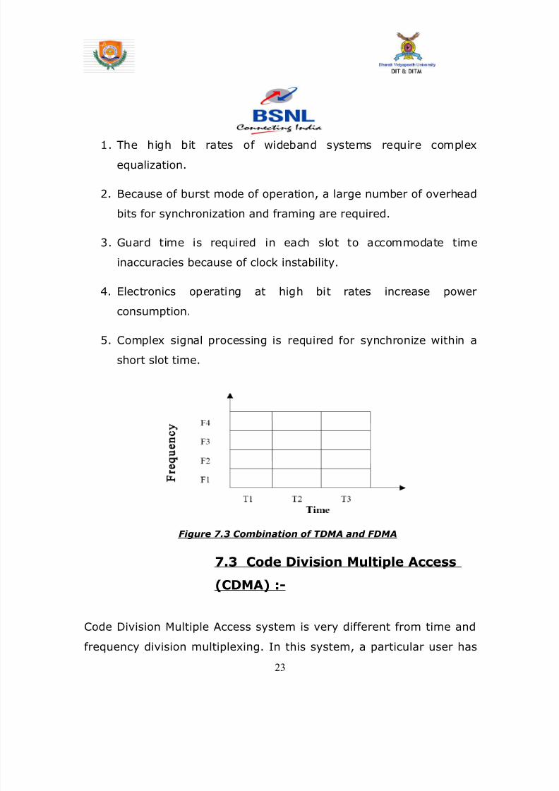
8142019 Dipti Report
httpslidepdfcomreaderfulldipti-report 2362
1 The high bit rates of wideband systems require complex
equalization
2 Because of burst mode of operation a large number of overhead
bits for synchronization and framing are required
3 Guard time is required in each slot to accommodate time
inaccuracies because of clock instability
4 Electronics operating at high bit rates increase power
consumption
5 Complex signal processing is required for synchronize within a
short slot time
Figure 73 Combination of TDMA and FDMA
73 Code Division Multiple Access
(CDMA) -
Code Division Multiple Access system is very different from time and
frequency division multiplexing In this system a particular user has
23
8142019 Dipti Report
httpslidepdfcomreaderfulldipti-report 2462
access to the entire bandwidth for the entire time duration The basic
principle of CDMA is that different codes are used to distinguish
between the different users Typically used forms of modulation are
Direct Sequence spread spectrum (DS-CDMA) frequency hopping or
Joint Detection CDMA (JDCDMA) Here a signal is generated that
spreads out over a wide bandwidth A code known as a spreading code
is used to perform this action By using a group of codes which are
orthogonal to each other it is possible to pick out a signal with a given
code in the presence of many other signals with different orthogonal
codes In fact many different baseband signals with 6 different
spreading codes can be modulated onto the same carrier to enable
many different users to be supported By using different orthogonal
codes interference between the signals is minimal Conversely when
signals are received from several mobile stations the base station is
able to isolate each one as they have different orthogonal spreading
codes
CDMA has a-Spectrum of-4507008009001700180019002100
MHz
Channel Bandwidth of 125 MHz
731 The Advantages of CDMA are -
1 CDMA has a soft capacity The more the number of codes more
the number of users
24
8142019 Dipti Report
httpslidepdfcomreaderfulldipti-report 2562
2 CDMA requires tight power control as it suffers for far-near
effect In other words a user close to the base station
transmitting with the same power as a user farther away will
drown the latterrsquos signal All signals must have more or less
equal power at the receiver
3 Rake receivers can be used to improve signal reception Time
delayed versions (a chip or more delayed) of the signal(multipath signals) can be collected and used to make bit level
decisions
4 Mobiles can switch base stations without switching carriers Two
base stations receive the mobile signal and the mobile is
receiving from two base stations
732 The Disadvantages of CDMA are -
1 The code length has to be carefully selected A large code length
can induce delay or even cause interference
2 Time synchronization is necessary
3 Soft handoff increases use of radio resources and hence can
reduce capacity
4 As the sum of the power received at and transmitted from a
base station has to constant a tight power control is needed
This can result in more handoffs
25
8142019 Dipti Report
httpslidepdfcomreaderfulldipti-report 2662
Figure 74 Code Division Multiple Access
74 Leased line
To transmit data between computer and electronic information
devices BSNL provides data communication services to its
subscribers It offers a choice of high medium and low speed leased
data circuits as well as dial-up lines Bandwidth is available on
demand in most of the cities Managed leased Line Network (MLLN)
offers flexibility of providing circuits with speeds of n x 64 Kbps up to
2 Mbps
Leased circuits are provided to subscribers for internal communication
between their officesfactories at various sites within a citytown or
different citiestown on point to point basis or on a network basis
interconnecting the various sites
26
8142019 Dipti Report
httpslidepdfcomreaderfulldipti-report 2762
741 Services provided by leased line -
1 Speech circuits
2 Data circuits
a Point to point data circuit
b Private data network
c Closed user group
3 Telegraph and tele ndash printer circuits
4 International leased circuit
742 Managed Leased Line Service (MLLN)
The MLLN is a Managed Leased Line Network system which is proposed
to provide Leased line connectivity The State-of-the-art technology
equipment MLLN is designed mainly for having effective control
monitor on the leased line so that the down time is very much
minimized
27
8142019 Dipti Report
httpslidepdfcomreaderfulldipti-report 2862
CHAPTER 8
INTRODUCTION
BROADBAND
The Broadband service is based on DSL technology (on the same
copper cable that is used for connecting telephone) countrywide
spanning 198 cities BSNL has commissioned a world class multi-
gigabit multi-protocol convergent IP infrastructure through National
Internet Backbone-II (NIB-II)
The services includes always-on broadband access to the Internet for
residential and business customers Content based services Video
multicasting Video-on-demand and Interactive gaming Audio and
Video conferencing IP Telephony Distance learning Messaging plain
and feature rich Multi-site MPLS VPNs with Quality of Service (QoS)
guarantees The subscriber accesses the above services through
Subscriber Service Selection System (SSSS) portal
28
8142019 Dipti Report
httpslidepdfcomreaderfulldipti-report 2962
BROADBAND is a form of internet service The only difference
between broadband and internet is the speed We receive broadband
and caller facility on the same copper wire with the help of a
SPLITTER which is a kind of low pass filter which separates a normal
call from the broadband data BSNL provides a staggering speed of 2
MBPS which is the fastest in India
Since we require less uploading compared to downloading so
broadband provides higher bandwidth and speed for downlink as
compared to uplink to suit our necessity Since the uplink and
downlink speed and bandwidth is different so a process called ADSL is
used
ADSL stands for Asymmetric Digital Subscriber Line It is a technology
that allows copper telephone pairs to be used to provide a broadband
connection It provides lsquoalways-onrsquo Internet connection that is
automatically established once the PC and ADSL modem are switched
on and instant log-in procedure is completed
lsquoAlways-Onrsquo means that the broadband sets up a permanent
connection to the Internet that lets you access the Internet as soon as
you switch on the computer and the CPE and do an instant log-in with
your user name and password There will be no separate Internet
telephone call charges
81 Benefits of ADSL
bull Fast downloads
bull At least 45 times and upto 35 times faster than dial-up
29
8142019 Dipti Report
httpslidepdfcomreaderfulldipti-report 3062
connection
bull Always on connection
bull Telephone and Internet access can be used together
bull No telephone call charges for internet surfing
bull Cost effective way to access Internet
bull A host of free content on the web can be downloaded faster
82 Main Objectives of Broadband are -
bull To provide high speed Internet connectivity (upto 8 Mbps)
bull To provide Virtual Private Network (VPN) service to the
broadband customers
bull To provide dial VPN service to MPLS VPN customers
bull To provide multicast video services video-on-demand etc
through the Broadband Remote Access Server (BRAS)
bull To provide a means to bill for the aforesaid services by either
time-based or volume-based billing It shall provide the
customer with the option to select the services through web
server
bull To provide both pre-paid and post paid broadband services
83 Services available through Broadband -
bull High speed Internet Access This is the always-on
Internet access service with speed ranging from 256 kbps to 8
Mbps
30
8142019 Dipti Report
httpslidepdfcomreaderfulldipti-report 3162
bull Bandwidth on Demand This facilitates customer to
change bandwidth as per his her requirement For example a
customer with 256 kbps can change to 1 Mbps during the video
Conferencing session
bull Multicasting This provides video multicast services for
application in distance education telemedicine etc
bull Dial VPN Service This service allows remote users to
access their private network securely over the NIB-II
infrastructure
bull Video and Audio Conferencing
bull Content based Services Like Video on Demand
Interactive Gaming Live and time shifted TV
31
8142019 Dipti Report
httpslidepdfcomreaderfulldipti-report 3262
Figure 81 Front Screen for Broadband Connection
CHAPTER 9
INTRODUCTION
32
8142019 Dipti Report
httpslidepdfcomreaderfulldipti-report 3362
GSM
GSM (Global System for Mobile communications) is an open digital
cellular technology used for transmitting mobile voice and data
services GSM differs from first generation wireless systems in that it
uses digital technology and time division multiple access transmission
methods
GSM is a circuit-switched system that divides each 200 kHz channel
into eight 25 kHz time-slots GSM operates in the 900MHz and 18GHz
bands in Europe and the 19GHz and 850MHz bands in the US The
850MHz band is also used for GSM and 3GSM in Australia Canada and
many South American countries
GSM supports data transfer speeds of up to 96 kbits allowing the
transmission of basic data services such as SMS (Short Message
Service) Another major benefit is its international roaming capability
allowing users to access the same services when travelling abroad as
at home This gives consumers seamless and same number
connectivity in more than 210 countries GSM satellite roaming has
also extended service access to areas where terrestrial coverage is not
available
91 GSM Interfaces -
33
8142019 Dipti Report
httpslidepdfcomreaderfulldipti-report 3462
II A - Interface
This is the interface within the GSM network architecture between the
BSS (Base Station Subsystem) and an MSC (Mobile Switching Centre)
The interface supports standard 64Kbps channels for signalling and
traffic The primary protocols on this interface are DTAP (Direct
Transfer Application Part) and BSSMAP (Base Station Subsystem
Management Application Part)
Figure 91 A - Interface
III Abis ndash Interface
The interface within the GSM architecture between the BTS (Base Transceiver
Station) and BSC (Base Station Controller) This interface is usually configured
using a 16Kbps slot structure
34
8142019 Dipti Report
httpslidepdfcomreaderfulldipti-report 3562
Figure 92 Abis Interface
Air ndash Interface (UM Interface)Interface between MS to BTS
B ndash Interface
Interface between MSC to VLR
C- Interface
Interface between HLR to MSC
D-Interface
Interface between HLR to VLR
35
8142019 Dipti Report
httpslidepdfcomreaderfulldipti-report 3662
E-Interface
Interface between MSC to MSC
F-Interface
Interface between MSC to EIR
G-InterfaceInterface between VLR to VLR
H-Interface
Interface between HLR to AUC
Figure 93 Mobile Tower having Antenna
36
8142019 Dipti Report
httpslidepdfcomreaderfulldipti-report 3762
Figure 94 GSM Architecture along with Interfaces
92 Architecture of the GSM network
The GSM network can be divided into four main parts
bull The Mobile Station (MS)
bull The Base Station Subsystem (BSS)
bull The Network and Switching Subsystem (NSS)
bull The Operation and Support Subsystem (OSS)
921 Mobile Station
A Mobile Station consists of two main elements
37
8142019 Dipti Report
httpslidepdfcomreaderfulldipti-report 3862
bull The mobile equipment or terminal
bull The Subscriber Identity Module (SIM)
Figure 95 Mobile Equipment and SIM
The Terminal
There are different types of terminals distinguished principally by their
power and application
bull The `fixed terminals are the ones installed in cars Their
maximum allowed output power is 20 W
bull The GSM portable terminals can also be installed in vehicles
Their maximum allowed output power is 8W
bull The handhels terminals have experienced the biggest success
thanks to thei weight and volume which are continuously
decreasing These terminals can emit up to 2 W The evolution of
technologies allows to decrease the maximum allowed power to
08 W
38
8142019 Dipti Report
httpslidepdfcomreaderfulldipti-report 3962
The SIM
The SIM is a smart card that identifies the terminal By inserting the
SIM card into the terminal the user can have access to all the
subscribed services Without the SIM card the terminal is not
operational
Another advantage of the SIM card is the mobility of the users In fact
the only element that personalizes a terminal is the SIM card
922 The Base Station Subsystem
The BSS connects the Mobile Station and the NSS It is in charge of
the transmission and reception The BSS can be divided into two parts
bull The Base Transceiver Station (BTS) or Base Station
bull The Base Station Controller (BSC)
9221 The Base Transceiver Station
The BTS corresponds to the transceivers and antennas used in
each cell of the network A BTS is usually placed in the center of a cell
Its transmitting power defines the size of a cell Each BTS has between
one and sixteen transceivers depending on the density of users in the
cell
39
8142019 Dipti Report
httpslidepdfcomreaderfulldipti-report 4062
40
8142019 Dipti Report
httpslidepdfcomreaderfulldipti-report 4162
Figure96 Picture of BTS
9222 The Base Station Controller
The BSC controls a group of BTS and manages their radio ressources
A BSC is principally in charge of handovers frequency hopping
exchange functions and control of the radio frequency power levels of
the BTSs
41
8142019 Dipti Report
httpslidepdfcomreaderfulldipti-report 4262
Figure 97 Picture of BSC
42
8142019 Dipti Report
httpslidepdfcomreaderfulldipti-report 4362
923 The Network and Switching Subsystem
Its main role is to manage the communications between the mobile
users and other users such as mobile users ISDN users fixed
telephony users etc It also includes data bases needed in order to
store information about the subscribers and to manage their mobility
The different components of the NSS are described below
92 31 The Mobile services Switching Center (MSC)
It is the central component of the NSS The MSC
performs the switching functions of the network It also provides
connection to other networks
9232 The Gateway Mobile services Switching Center
(GMSC)
A gateway is a node interconnecting two networks The GMSC is the
interface between the mobile cellular network and the PSTN It is in
charge of routing calls from the fixed network towards a GSM user
The GMSC is often implemented in the same machines as the MSC
92 33 Home location register (HLR)
HLR stores information of subscriber belonging to the covering area of
MSC It also stores the current location of these subscribers and the
service to which they have access
43
8142019 Dipti Report
httpslidepdfcomreaderfulldipti-report 4462
9234 Visitor location register (VLR)
VLR contains information from subscriberrsquos HLR necessary in order to
provide the subscribed services to visiting users
VLR is always implemented together with a MSC soothe area under
control of the MSC is also the area under control of the VLR
9235 Authentication center (AUC)
AUC register is used for security purpose It helps to verify the userrsquos
identity
9236 Equipment identity register (EIR )
EIR contains a list of all valid terminals The EIR allows the forbid calls
from stolen or unauthorized terminals
92 37 The GSM Interworking Unit (GIWU)
The GIWU corresponds to an interface to various networks for data
communications During these communications the transmission of
speech and data can be alternated
924 The Operation and Support Subsystem (OSS)
The OSS is connected to the different components of the NSS and to
the BSC in order to control and monitor the GSM system It is also in
charge of controlling the traffic load of the BSS
44
8142019 Dipti Report
httpslidepdfcomreaderfulldipti-report 4562
Figure 98 BLOCK DIAGRAM OF MOBILE TOWER AND
TRANSMISSION
93 The GSM functions
In this paragraph the description of the GSM network is focused on
the differents functions to fulfil by the network and not on its physical
components In GSM five main functions can be defined
bull Transmission
bull Radio Resources management (RR)
bull Mobility Management (MM)
bull Communication Management (CM)
bull Operation Administration and Maintenance (OAM)
45
8142019 Dipti Report
httpslidepdfcomreaderfulldipti-report 4662
94 GSM Frequencies
In principle the GSM system can be implemented in any frequency
band However there are several bands where GSM terminals are or
will shortly be available Furthermore GSM terminals may incorporate
one or more of the GSM frequency bands listed below to facilitate
roaming on a global basis
Frequency Range
GSM400 4504 - 4576 MHz paired with 4604 - 4676
MHz
or
4788 - 486 MHz paired with 4888 - 496 MHz
GSM 850 824 - 849 MHz paired with 869 - 894 MHz
GSM900 880 - 915 MHz paired with 925 - 960 MHz
GSM1800 1710 - 1785 MHz paired with 1805 - 1880 MHz
GSM1900 1850 - 1910 MHz paired with 1930 - 1990 MHz
95 Frequency allocation
Two frequency bands of 25 Mhz each one have been allocated for the
GSM system
bull The band 890-915 Mhz has been allocated for the uplink
direction (transmitting from the mobile station to the base
station)
46
8142019 Dipti Report
httpslidepdfcomreaderfulldipti-report 4762
bull The band 935-960 Mhz has been allocated for the downlink
direction (transmitting from the base station to the mobile
station)
But not all the countries can use the whole GSM frequency bands
This is due principally to military reasons and to the existence of
previous analog systems using part of the two 25 Mhz frequency
bands
Traffic is measured in ERLANG
BSC Capacity is 1min 5000 ERLANG
Now in 3G in respect of BSC MSC
RNC(Radio Network Control) is used
CHAPTER 10
47
8142019 Dipti Report
httpslidepdfcomreaderfulldipti-report 4862
INTRODUCTION
MAIN DISTRIBUTION FRAME (MDF)
The main distribution frame acts as a link between the
exchange indoor and the exchange outdoor It not only
connects the exchange with the subscriber but also protects
the exchange from environmental hazards such as lightning
strike
There are two sides in a MDF -
101 Line side - The line side belongs to the outdoor The
subscriber is connected to the exchange via the MDF In the
line side there are analog connections
This side of the exchange consists of verticals Each vertical
has 100 trans and receive pairs connected to it ie 100
subscribers are connected to the exchange via one vertical
Each vertical corresponds to a particular pillar The line wires
emanating from the verticals are connected to a cabinet
from where it is taken to a pillar which then is connected to
48
8142019 Dipti Report
httpslidepdfcomreaderfulldipti-report 4962
a distribution pole (DP) From here the lines are distributed
to the subscribers
For line testing on the line side the dial tone is tested on the
vertical first If it is found to be ok then the testing is carried
forward to the cabinet From here line wires are carried
forward in a cluster of around 100 pairs to the pillar A pillar
is usually located in the central part of an area where the
pillar is established so that distribution is convenient and
less expensive One distribution pole is set up to provide
connection to around 15 to 20 homes From here the
subscribers are directly connected
102 Exchange side - Exchange side belongs to the
exchange On the exchange side of the MDF the connections
are DigitalThe connection between the
exchange and the subscriber is made in various stages On
the exchange side the MDF is directly connected to the DLU
in the SN (Switching Network) In the MDF the two sides
49
8142019 Dipti Report
httpslidepdfcomreaderfulldipti-report 5062
are connected through a jumper wire The line testing for
the exchange is done first here using a dial tone checker
For rectifying errors each subscriber is assigned an
Equipment Number (NE) This number is the identification
mark of the subscriber for the exchange It represents the
location in the DLU from where the connection is provided
The DLU is then connected to the LTG (Line Trunk Groups)
from here the switching network is connected
CHAPTER 11
50
8142019 Dipti Report
httpslidepdfcomreaderfulldipti-report 5162
INTRODUCTION
THE POWER PLANT
Power Plant is the main part of an Exchange It provide uninterrupted
power to the exchange continuously it also plays the role of converting
AC power to DC power
The arrangement made has one active and two standby systems for
supplying power This makes the system extremely reliable even in the
areas with acute power shortage Options like maintenance free
batteries (VRLA) also make it cost effective
There are three supply options in the power plant
bull The AC mains
bull The Value Regulated Lead Acid battery set
bull The engine alternator
111 The AC Mains
The exchange requires a constant supply voltage of 48V (DC) in the
running condition So the voltage obtained from which is 66 KV needs
51
8142019 Dipti Report
httpslidepdfcomreaderfulldipti-report 5262
to be stepped down and rectified to DC voltage This function is
performed by the float rectifier unit
112 The Battery Set
There are two sets of VRLA batteries which are maintenance free
batteries Each set is capable of providing the required 48V DC supply
and have a capacity of 4000 AH (Ampere Hour) They are named as
set A and set B One set is active while the other set is available for
standby In case AC mains power is on both the sets of batteries get
charged As soon as there is a power cut the load gets switched over
to the battery set and one of the sets gets active while the other is
available for standby But even this source cannot be trusted for very
long durations as each set is capable of sustaining the load only for
about 3 hours So we need another alternative to provide a fool proof
system This calls for the use of the engine alternator
1113 The Engine Alternator
Usually the battery set is always kept for standby operation In case
there is a power cut the battery set operates hardly for 5 to 10
minutes which is the time taken for the alternator to start
There are also two sets of generators which are rated as follows
bull 66 KV415V voltage rating with moisture absorber
bull 200 KVA power rating
52
8142019 Dipti Report
httpslidepdfcomreaderfulldipti-report 5362
CHAPTER 12
INTRODUCTION
OPERATION AND MAINTENANCE TERMINAL
On the basis of Operation and maintenance terminal Function it has
been grouped into following categories
121 OPERATING FUNCTIONS
1 Charging function
2 Continuous connectivity management
3 Memory management of Translator
122 SUPERVISION FUNCTIONS
1 Circuit tests
2 Line and subscriber set tests
3 Load and traffic observation
123 MAINTENANCE FUNCTIONS
1 Maintenance of exchange control unit memories
2 Fault location and trouble-shooting aid function
3 Telephone equipment position
53
8142019 Dipti Report
httpslidepdfcomreaderfulldipti-report 5462
CHAPTER 13
INTRODUCTION
PULSE CODE MODULATION
PCM is a process which converts a continuous analog signal into digital
signals It is a Multichannel transmission technique that explores the
advantage of digital transmission over analog transmission It only
realizes the advantages of improved transmission limits greater noise
immunity lesser distortion of dial pulses but also economy
Converting continuous analog signal into digital signals is
carried out in three stages-
131 Sampling- Sampling is a periodical
measurement of the value of the analog signal A sampled
data contains all the information of the signal if the
sampling frequency is at least twice the highest frequency
of the signal to be sampled As the signals in telephony are
band limited to 300-3400Hz a sampling are frequency of
8000Hz ie every 125 micro seconds is sufficient
54
8142019 Dipti Report
httpslidepdfcomreaderfulldipti-report 5562
132 Quantizing - representation of their amplitude is forced to
take certain value To ensure that the ratio between signal amplitude
and errors introduced by quantized and encoded (companding) law is
applied
133 Encoding - PAM signals are quantized and encoded into 8
bit symmetrical binary code and transmitted on line during the time
slot allotted to that channel as PCM signals
At the receive side these PCM signals are decoded into PAM
signals and smoothed out by passing through low-pass filters to filters
to get back originals signals
This PCM system can support 30 simultaneous telephone conversation
and optionally 8 telegraphteleprinter channels on one line Individual
channels have a transmission speed of 64 Kbitss and the total
transmission rate for all 32 channels in the system is 2048 Kbitss
55
8142019 Dipti Report
httpslidepdfcomreaderfulldipti-report 5662
CHAPTER 14
INTRODUCTION
SWITCHING
There are two types of switching namely CIRCUIT Switching and
PACKET Switching
141 CIRCUIT SWITCHING - A circuit switching network is onethat establishes a dedicated circuit between nodes and terminals
before the users may communicate Each circuit that is dedicated
cannot be used by other callers until the circuit is released and a new
connection is set up Even if no actual communication is taking place in
a dedicated circuit then that channel still remains unavailable to other
users Channels that are available for new calls to be set up are said to
be idle Early telephone exchanges are a suitable example of circuitswitching
142 PACKET SWITCHING - Packet switching is a
communications paradigm in which packets are routed between nodes
over data links shared with other traffic This contrasts with the other
56
8142019 Dipti Report
httpslidepdfcomreaderfulldipti-report 5762
principal paradigm circuit switching which sets up a dedicated
connection between the two nodes for their exclusive use for the
duration of the communication Packet switching is used to optimize
the use of the channel capacity available in a network to minimize the
transmission latency (ie the time it takes for data to pass across the
network) and to increase robustness of communication
143 Circuit Switching vs Packet
Switching
In principle circuit switching and packet switching both are used in
high-capacity networks In circuit-switched networks network
resources are static set in ldquocopperrdquo if you will from the sender to
receiver before the start of the transfer thus creating a ldquocircuitrdquo The
resources remain dedicated to the circuit during the entire transfer and
the entire message follows the same path In packet-switched
networks the message is broken into packets each of which can take
a different route to the destination where the packets are recompiled
into the original message Circuit switching contrasts with packet
switching which splits traffic data (for instance digital representation
of sound or computer data) into chunks called packets that are
routed over a shared network Packet switching networks do not
require a circuit to be established and allow many pairs of nodes to
communicate almost simultaneously over the same channel Each
57
8142019 Dipti Report
httpslidepdfcomreaderfulldipti-report 5862
packet is individually addressed precluding the need for a dedicated
path to help the packet find its way to its destination
CHAPTER 15
CONCLUSION
This Practical Training has given me an opportunity to know about various
technologies working behind in todayrsquos advanced world of telecommunication
All those that we read in our Book only theoretically by this training I observe all
those practically I come across different units in telecom exchange like
E10BOCBEWSD Mobile (GSM) BSC and BTS MDF and Power Plant
and Broadband I not only watch those equipment but also know about those
there working there functions and also how by work to provide us facility of
telecomI am very grateful to those persons who helped directly amp
indirectly in the successful completion of this practical training and this will
surely be fruitful in future
58
8142019 Dipti Report
httpslidepdfcomreaderfulldipti-report 5962
CHAPTER 16
APPENDIX
161 Loading statement of Jamshedpur OCB-283Capacity of the TAXndash22K Loading ndash 5915
Station IC OG Between Total PCM
Arra Nil Nil 30 1
Ambala Nil Nil 30 1
Bangalore Nil Nil 61 2
Bhagalpur Nil Nil 60 2
Chennai Nil Nil 30 1
Cuttack Nil Nil 184 6
Daltengung Nil Nil 30 1
Darbhanga Nil Nil 60 2
Delhi bsnl Nil Nil 122 4Delhi mtnl Nil Nil 91 3
Dhanbad Nil Nil 122 4
Dumka Nil Nil 30 1
Ericson1 Nil Nil 494 16
Ericson2 Ni Nil 122 4
Gaya Nil Nil 61 2
Hajipur Nil Nil 30 1
Hazaribag Nil Nil 91 3
Hyderabad Nil Nil 123 4
Kolkata Nil Nil 246 8
Kharagpur Nil Nil 91 3
Katihar Nil Nil 30 1
Lucknow Nil Nil 90 3
Mumbai bsnl Nil Nil 61 2
Mumbai mtnl Nil Nil 62 2
59
8142019 Dipti Report
httpslidepdfcomreaderfulldipti-report 6062
Munger Nil Nil 30 1
Muzafferpur Nil Nil 61 2
Nortel Nil Nil 587 19
Purulia Nil Nil 61 2
Patna Nil Nil 151 5
Patliputr Nil Nil 122 8
Raurkela Nil Nil 91 3
Ranchi 15 45 680 24
Sasaram Nil Nil 30 1
Saharsa Nil Nil 30 1Sakla Nil Nil 153 5
Sambalpur Nil Nil 30 1
Tarang Nil Nil 154 5
Baripada Nil Nil 60 2
MSCA Nil Nil 309 10
Msc bokaro Nil Nil 618 20
Total 15 45 5518 182
162 OCB ndash 283 MAIN TELEPHONE EXCHANGES
EXCHANGE CAPACITY PCM
Main Exchange 12k -
Rsu Telco 11256 15
Rsu Adityapur 3k -
Rsu Sidhgora 4k 12
Rsu Mani fit 4256k 11
Rsu Govindpur 2k 10
Rsu Tatanagar 4256k 14
Rsu Parsudih 4k 11
Dlcjsr 6rt -Dlc Parsudih 2rt -
DlcTelco 1rt -
RsuKharkai 1k -
Ghatsila 6585 12
Bahragora 6594 3
Chaibasa 6582 12
60
8142019 Dipti Report
httpslidepdfcomreaderfulldipti-report 6162
Chakardharpur 6587 5
Manoharpur 6593 2
Saraikela 6597 7
Chandil 6591 -
Jhinkpani 6589 -
Jagannathpur 6588 -
Giriburu 6596 4
Nowamundi 6596 5
Kharzwara 6583 -
163 PHONE CODES AND THEIR EXCHANGE CODE
61
PHONE CODE EXCHANGE
2758 JSR
2756 JSR
2421 JSR
243 JSR
244 JSR
248 JSR
222 JSR223 JSR
265 SNK
240 ADR
220 ADR
2370-3 ADR
2380-3 ADR
2386-87 GMR
246 amp 236 MNG
29 7 DIGIT WJSR
2270 GVP2277 GVP
2290-95 TAT
2296 PSD
230-231 KDM
234 GOL
226228 TLC
221 SDG
232 LIC
2249 KHL
8142019 Dipti Report
httpslidepdfcomreaderfulldipti-report 6262
8142019 Dipti Report
httpslidepdfcomreaderfulldipti-report 2562
2 CDMA requires tight power control as it suffers for far-near
effect In other words a user close to the base station
transmitting with the same power as a user farther away will
drown the latterrsquos signal All signals must have more or less
equal power at the receiver
3 Rake receivers can be used to improve signal reception Time
delayed versions (a chip or more delayed) of the signal(multipath signals) can be collected and used to make bit level
decisions
4 Mobiles can switch base stations without switching carriers Two
base stations receive the mobile signal and the mobile is
receiving from two base stations
732 The Disadvantages of CDMA are -
1 The code length has to be carefully selected A large code length
can induce delay or even cause interference
2 Time synchronization is necessary
3 Soft handoff increases use of radio resources and hence can
reduce capacity
4 As the sum of the power received at and transmitted from a
base station has to constant a tight power control is needed
This can result in more handoffs
25
8142019 Dipti Report
httpslidepdfcomreaderfulldipti-report 2662
Figure 74 Code Division Multiple Access
74 Leased line
To transmit data between computer and electronic information
devices BSNL provides data communication services to its
subscribers It offers a choice of high medium and low speed leased
data circuits as well as dial-up lines Bandwidth is available on
demand in most of the cities Managed leased Line Network (MLLN)
offers flexibility of providing circuits with speeds of n x 64 Kbps up to
2 Mbps
Leased circuits are provided to subscribers for internal communication
between their officesfactories at various sites within a citytown or
different citiestown on point to point basis or on a network basis
interconnecting the various sites
26
8142019 Dipti Report
httpslidepdfcomreaderfulldipti-report 2762
741 Services provided by leased line -
1 Speech circuits
2 Data circuits
a Point to point data circuit
b Private data network
c Closed user group
3 Telegraph and tele ndash printer circuits
4 International leased circuit
742 Managed Leased Line Service (MLLN)
The MLLN is a Managed Leased Line Network system which is proposed
to provide Leased line connectivity The State-of-the-art technology
equipment MLLN is designed mainly for having effective control
monitor on the leased line so that the down time is very much
minimized
27
8142019 Dipti Report
httpslidepdfcomreaderfulldipti-report 2862
CHAPTER 8
INTRODUCTION
BROADBAND
The Broadband service is based on DSL technology (on the same
copper cable that is used for connecting telephone) countrywide
spanning 198 cities BSNL has commissioned a world class multi-
gigabit multi-protocol convergent IP infrastructure through National
Internet Backbone-II (NIB-II)
The services includes always-on broadband access to the Internet for
residential and business customers Content based services Video
multicasting Video-on-demand and Interactive gaming Audio and
Video conferencing IP Telephony Distance learning Messaging plain
and feature rich Multi-site MPLS VPNs with Quality of Service (QoS)
guarantees The subscriber accesses the above services through
Subscriber Service Selection System (SSSS) portal
28
8142019 Dipti Report
httpslidepdfcomreaderfulldipti-report 2962
BROADBAND is a form of internet service The only difference
between broadband and internet is the speed We receive broadband
and caller facility on the same copper wire with the help of a
SPLITTER which is a kind of low pass filter which separates a normal
call from the broadband data BSNL provides a staggering speed of 2
MBPS which is the fastest in India
Since we require less uploading compared to downloading so
broadband provides higher bandwidth and speed for downlink as
compared to uplink to suit our necessity Since the uplink and
downlink speed and bandwidth is different so a process called ADSL is
used
ADSL stands for Asymmetric Digital Subscriber Line It is a technology
that allows copper telephone pairs to be used to provide a broadband
connection It provides lsquoalways-onrsquo Internet connection that is
automatically established once the PC and ADSL modem are switched
on and instant log-in procedure is completed
lsquoAlways-Onrsquo means that the broadband sets up a permanent
connection to the Internet that lets you access the Internet as soon as
you switch on the computer and the CPE and do an instant log-in with
your user name and password There will be no separate Internet
telephone call charges
81 Benefits of ADSL
bull Fast downloads
bull At least 45 times and upto 35 times faster than dial-up
29
8142019 Dipti Report
httpslidepdfcomreaderfulldipti-report 3062
connection
bull Always on connection
bull Telephone and Internet access can be used together
bull No telephone call charges for internet surfing
bull Cost effective way to access Internet
bull A host of free content on the web can be downloaded faster
82 Main Objectives of Broadband are -
bull To provide high speed Internet connectivity (upto 8 Mbps)
bull To provide Virtual Private Network (VPN) service to the
broadband customers
bull To provide dial VPN service to MPLS VPN customers
bull To provide multicast video services video-on-demand etc
through the Broadband Remote Access Server (BRAS)
bull To provide a means to bill for the aforesaid services by either
time-based or volume-based billing It shall provide the
customer with the option to select the services through web
server
bull To provide both pre-paid and post paid broadband services
83 Services available through Broadband -
bull High speed Internet Access This is the always-on
Internet access service with speed ranging from 256 kbps to 8
Mbps
30
8142019 Dipti Report
httpslidepdfcomreaderfulldipti-report 3162
bull Bandwidth on Demand This facilitates customer to
change bandwidth as per his her requirement For example a
customer with 256 kbps can change to 1 Mbps during the video
Conferencing session
bull Multicasting This provides video multicast services for
application in distance education telemedicine etc
bull Dial VPN Service This service allows remote users to
access their private network securely over the NIB-II
infrastructure
bull Video and Audio Conferencing
bull Content based Services Like Video on Demand
Interactive Gaming Live and time shifted TV
31
8142019 Dipti Report
httpslidepdfcomreaderfulldipti-report 3262
Figure 81 Front Screen for Broadband Connection
CHAPTER 9
INTRODUCTION
32
8142019 Dipti Report
httpslidepdfcomreaderfulldipti-report 3362
GSM
GSM (Global System for Mobile communications) is an open digital
cellular technology used for transmitting mobile voice and data
services GSM differs from first generation wireless systems in that it
uses digital technology and time division multiple access transmission
methods
GSM is a circuit-switched system that divides each 200 kHz channel
into eight 25 kHz time-slots GSM operates in the 900MHz and 18GHz
bands in Europe and the 19GHz and 850MHz bands in the US The
850MHz band is also used for GSM and 3GSM in Australia Canada and
many South American countries
GSM supports data transfer speeds of up to 96 kbits allowing the
transmission of basic data services such as SMS (Short Message
Service) Another major benefit is its international roaming capability
allowing users to access the same services when travelling abroad as
at home This gives consumers seamless and same number
connectivity in more than 210 countries GSM satellite roaming has
also extended service access to areas where terrestrial coverage is not
available
91 GSM Interfaces -
33
8142019 Dipti Report
httpslidepdfcomreaderfulldipti-report 3462
II A - Interface
This is the interface within the GSM network architecture between the
BSS (Base Station Subsystem) and an MSC (Mobile Switching Centre)
The interface supports standard 64Kbps channels for signalling and
traffic The primary protocols on this interface are DTAP (Direct
Transfer Application Part) and BSSMAP (Base Station Subsystem
Management Application Part)
Figure 91 A - Interface
III Abis ndash Interface
The interface within the GSM architecture between the BTS (Base Transceiver
Station) and BSC (Base Station Controller) This interface is usually configured
using a 16Kbps slot structure
34
8142019 Dipti Report
httpslidepdfcomreaderfulldipti-report 3562
Figure 92 Abis Interface
Air ndash Interface (UM Interface)Interface between MS to BTS
B ndash Interface
Interface between MSC to VLR
C- Interface
Interface between HLR to MSC
D-Interface
Interface between HLR to VLR
35
8142019 Dipti Report
httpslidepdfcomreaderfulldipti-report 3662
E-Interface
Interface between MSC to MSC
F-Interface
Interface between MSC to EIR
G-InterfaceInterface between VLR to VLR
H-Interface
Interface between HLR to AUC
Figure 93 Mobile Tower having Antenna
36
8142019 Dipti Report
httpslidepdfcomreaderfulldipti-report 3762
Figure 94 GSM Architecture along with Interfaces
92 Architecture of the GSM network
The GSM network can be divided into four main parts
bull The Mobile Station (MS)
bull The Base Station Subsystem (BSS)
bull The Network and Switching Subsystem (NSS)
bull The Operation and Support Subsystem (OSS)
921 Mobile Station
A Mobile Station consists of two main elements
37
8142019 Dipti Report
httpslidepdfcomreaderfulldipti-report 3862
bull The mobile equipment or terminal
bull The Subscriber Identity Module (SIM)
Figure 95 Mobile Equipment and SIM
The Terminal
There are different types of terminals distinguished principally by their
power and application
bull The `fixed terminals are the ones installed in cars Their
maximum allowed output power is 20 W
bull The GSM portable terminals can also be installed in vehicles
Their maximum allowed output power is 8W
bull The handhels terminals have experienced the biggest success
thanks to thei weight and volume which are continuously
decreasing These terminals can emit up to 2 W The evolution of
technologies allows to decrease the maximum allowed power to
08 W
38
8142019 Dipti Report
httpslidepdfcomreaderfulldipti-report 3962
The SIM
The SIM is a smart card that identifies the terminal By inserting the
SIM card into the terminal the user can have access to all the
subscribed services Without the SIM card the terminal is not
operational
Another advantage of the SIM card is the mobility of the users In fact
the only element that personalizes a terminal is the SIM card
922 The Base Station Subsystem
The BSS connects the Mobile Station and the NSS It is in charge of
the transmission and reception The BSS can be divided into two parts
bull The Base Transceiver Station (BTS) or Base Station
bull The Base Station Controller (BSC)
9221 The Base Transceiver Station
The BTS corresponds to the transceivers and antennas used in
each cell of the network A BTS is usually placed in the center of a cell
Its transmitting power defines the size of a cell Each BTS has between
one and sixteen transceivers depending on the density of users in the
cell
39
8142019 Dipti Report
httpslidepdfcomreaderfulldipti-report 4062
40
8142019 Dipti Report
httpslidepdfcomreaderfulldipti-report 4162
Figure96 Picture of BTS
9222 The Base Station Controller
The BSC controls a group of BTS and manages their radio ressources
A BSC is principally in charge of handovers frequency hopping
exchange functions and control of the radio frequency power levels of
the BTSs
41
8142019 Dipti Report
httpslidepdfcomreaderfulldipti-report 4262
Figure 97 Picture of BSC
42
8142019 Dipti Report
httpslidepdfcomreaderfulldipti-report 4362
923 The Network and Switching Subsystem
Its main role is to manage the communications between the mobile
users and other users such as mobile users ISDN users fixed
telephony users etc It also includes data bases needed in order to
store information about the subscribers and to manage their mobility
The different components of the NSS are described below
92 31 The Mobile services Switching Center (MSC)
It is the central component of the NSS The MSC
performs the switching functions of the network It also provides
connection to other networks
9232 The Gateway Mobile services Switching Center
(GMSC)
A gateway is a node interconnecting two networks The GMSC is the
interface between the mobile cellular network and the PSTN It is in
charge of routing calls from the fixed network towards a GSM user
The GMSC is often implemented in the same machines as the MSC
92 33 Home location register (HLR)
HLR stores information of subscriber belonging to the covering area of
MSC It also stores the current location of these subscribers and the
service to which they have access
43
8142019 Dipti Report
httpslidepdfcomreaderfulldipti-report 4462
9234 Visitor location register (VLR)
VLR contains information from subscriberrsquos HLR necessary in order to
provide the subscribed services to visiting users
VLR is always implemented together with a MSC soothe area under
control of the MSC is also the area under control of the VLR
9235 Authentication center (AUC)
AUC register is used for security purpose It helps to verify the userrsquos
identity
9236 Equipment identity register (EIR )
EIR contains a list of all valid terminals The EIR allows the forbid calls
from stolen or unauthorized terminals
92 37 The GSM Interworking Unit (GIWU)
The GIWU corresponds to an interface to various networks for data
communications During these communications the transmission of
speech and data can be alternated
924 The Operation and Support Subsystem (OSS)
The OSS is connected to the different components of the NSS and to
the BSC in order to control and monitor the GSM system It is also in
charge of controlling the traffic load of the BSS
44
8142019 Dipti Report
httpslidepdfcomreaderfulldipti-report 4562
Figure 98 BLOCK DIAGRAM OF MOBILE TOWER AND
TRANSMISSION
93 The GSM functions
In this paragraph the description of the GSM network is focused on
the differents functions to fulfil by the network and not on its physical
components In GSM five main functions can be defined
bull Transmission
bull Radio Resources management (RR)
bull Mobility Management (MM)
bull Communication Management (CM)
bull Operation Administration and Maintenance (OAM)
45
8142019 Dipti Report
httpslidepdfcomreaderfulldipti-report 4662
94 GSM Frequencies
In principle the GSM system can be implemented in any frequency
band However there are several bands where GSM terminals are or
will shortly be available Furthermore GSM terminals may incorporate
one or more of the GSM frequency bands listed below to facilitate
roaming on a global basis
Frequency Range
GSM400 4504 - 4576 MHz paired with 4604 - 4676
MHz
or
4788 - 486 MHz paired with 4888 - 496 MHz
GSM 850 824 - 849 MHz paired with 869 - 894 MHz
GSM900 880 - 915 MHz paired with 925 - 960 MHz
GSM1800 1710 - 1785 MHz paired with 1805 - 1880 MHz
GSM1900 1850 - 1910 MHz paired with 1930 - 1990 MHz
95 Frequency allocation
Two frequency bands of 25 Mhz each one have been allocated for the
GSM system
bull The band 890-915 Mhz has been allocated for the uplink
direction (transmitting from the mobile station to the base
station)
46
8142019 Dipti Report
httpslidepdfcomreaderfulldipti-report 4762
bull The band 935-960 Mhz has been allocated for the downlink
direction (transmitting from the base station to the mobile
station)
But not all the countries can use the whole GSM frequency bands
This is due principally to military reasons and to the existence of
previous analog systems using part of the two 25 Mhz frequency
bands
Traffic is measured in ERLANG
BSC Capacity is 1min 5000 ERLANG
Now in 3G in respect of BSC MSC
RNC(Radio Network Control) is used
CHAPTER 10
47
8142019 Dipti Report
httpslidepdfcomreaderfulldipti-report 4862
INTRODUCTION
MAIN DISTRIBUTION FRAME (MDF)
The main distribution frame acts as a link between the
exchange indoor and the exchange outdoor It not only
connects the exchange with the subscriber but also protects
the exchange from environmental hazards such as lightning
strike
There are two sides in a MDF -
101 Line side - The line side belongs to the outdoor The
subscriber is connected to the exchange via the MDF In the
line side there are analog connections
This side of the exchange consists of verticals Each vertical
has 100 trans and receive pairs connected to it ie 100
subscribers are connected to the exchange via one vertical
Each vertical corresponds to a particular pillar The line wires
emanating from the verticals are connected to a cabinet
from where it is taken to a pillar which then is connected to
48
8142019 Dipti Report
httpslidepdfcomreaderfulldipti-report 4962
a distribution pole (DP) From here the lines are distributed
to the subscribers
For line testing on the line side the dial tone is tested on the
vertical first If it is found to be ok then the testing is carried
forward to the cabinet From here line wires are carried
forward in a cluster of around 100 pairs to the pillar A pillar
is usually located in the central part of an area where the
pillar is established so that distribution is convenient and
less expensive One distribution pole is set up to provide
connection to around 15 to 20 homes From here the
subscribers are directly connected
102 Exchange side - Exchange side belongs to the
exchange On the exchange side of the MDF the connections
are DigitalThe connection between the
exchange and the subscriber is made in various stages On
the exchange side the MDF is directly connected to the DLU
in the SN (Switching Network) In the MDF the two sides
49
8142019 Dipti Report
httpslidepdfcomreaderfulldipti-report 5062
are connected through a jumper wire The line testing for
the exchange is done first here using a dial tone checker
For rectifying errors each subscriber is assigned an
Equipment Number (NE) This number is the identification
mark of the subscriber for the exchange It represents the
location in the DLU from where the connection is provided
The DLU is then connected to the LTG (Line Trunk Groups)
from here the switching network is connected
CHAPTER 11
50
8142019 Dipti Report
httpslidepdfcomreaderfulldipti-report 5162
INTRODUCTION
THE POWER PLANT
Power Plant is the main part of an Exchange It provide uninterrupted
power to the exchange continuously it also plays the role of converting
AC power to DC power
The arrangement made has one active and two standby systems for
supplying power This makes the system extremely reliable even in the
areas with acute power shortage Options like maintenance free
batteries (VRLA) also make it cost effective
There are three supply options in the power plant
bull The AC mains
bull The Value Regulated Lead Acid battery set
bull The engine alternator
111 The AC Mains
The exchange requires a constant supply voltage of 48V (DC) in the
running condition So the voltage obtained from which is 66 KV needs
51
8142019 Dipti Report
httpslidepdfcomreaderfulldipti-report 5262
to be stepped down and rectified to DC voltage This function is
performed by the float rectifier unit
112 The Battery Set
There are two sets of VRLA batteries which are maintenance free
batteries Each set is capable of providing the required 48V DC supply
and have a capacity of 4000 AH (Ampere Hour) They are named as
set A and set B One set is active while the other set is available for
standby In case AC mains power is on both the sets of batteries get
charged As soon as there is a power cut the load gets switched over
to the battery set and one of the sets gets active while the other is
available for standby But even this source cannot be trusted for very
long durations as each set is capable of sustaining the load only for
about 3 hours So we need another alternative to provide a fool proof
system This calls for the use of the engine alternator
1113 The Engine Alternator
Usually the battery set is always kept for standby operation In case
there is a power cut the battery set operates hardly for 5 to 10
minutes which is the time taken for the alternator to start
There are also two sets of generators which are rated as follows
bull 66 KV415V voltage rating with moisture absorber
bull 200 KVA power rating
52
8142019 Dipti Report
httpslidepdfcomreaderfulldipti-report 5362
CHAPTER 12
INTRODUCTION
OPERATION AND MAINTENANCE TERMINAL
On the basis of Operation and maintenance terminal Function it has
been grouped into following categories
121 OPERATING FUNCTIONS
1 Charging function
2 Continuous connectivity management
3 Memory management of Translator
122 SUPERVISION FUNCTIONS
1 Circuit tests
2 Line and subscriber set tests
3 Load and traffic observation
123 MAINTENANCE FUNCTIONS
1 Maintenance of exchange control unit memories
2 Fault location and trouble-shooting aid function
3 Telephone equipment position
53
8142019 Dipti Report
httpslidepdfcomreaderfulldipti-report 5462
CHAPTER 13
INTRODUCTION
PULSE CODE MODULATION
PCM is a process which converts a continuous analog signal into digital
signals It is a Multichannel transmission technique that explores the
advantage of digital transmission over analog transmission It only
realizes the advantages of improved transmission limits greater noise
immunity lesser distortion of dial pulses but also economy
Converting continuous analog signal into digital signals is
carried out in three stages-
131 Sampling- Sampling is a periodical
measurement of the value of the analog signal A sampled
data contains all the information of the signal if the
sampling frequency is at least twice the highest frequency
of the signal to be sampled As the signals in telephony are
band limited to 300-3400Hz a sampling are frequency of
8000Hz ie every 125 micro seconds is sufficient
54
8142019 Dipti Report
httpslidepdfcomreaderfulldipti-report 5562
132 Quantizing - representation of their amplitude is forced to
take certain value To ensure that the ratio between signal amplitude
and errors introduced by quantized and encoded (companding) law is
applied
133 Encoding - PAM signals are quantized and encoded into 8
bit symmetrical binary code and transmitted on line during the time
slot allotted to that channel as PCM signals
At the receive side these PCM signals are decoded into PAM
signals and smoothed out by passing through low-pass filters to filters
to get back originals signals
This PCM system can support 30 simultaneous telephone conversation
and optionally 8 telegraphteleprinter channels on one line Individual
channels have a transmission speed of 64 Kbitss and the total
transmission rate for all 32 channels in the system is 2048 Kbitss
55
8142019 Dipti Report
httpslidepdfcomreaderfulldipti-report 5662
CHAPTER 14
INTRODUCTION
SWITCHING
There are two types of switching namely CIRCUIT Switching and
PACKET Switching
141 CIRCUIT SWITCHING - A circuit switching network is onethat establishes a dedicated circuit between nodes and terminals
before the users may communicate Each circuit that is dedicated
cannot be used by other callers until the circuit is released and a new
connection is set up Even if no actual communication is taking place in
a dedicated circuit then that channel still remains unavailable to other
users Channels that are available for new calls to be set up are said to
be idle Early telephone exchanges are a suitable example of circuitswitching
142 PACKET SWITCHING - Packet switching is a
communications paradigm in which packets are routed between nodes
over data links shared with other traffic This contrasts with the other
56
8142019 Dipti Report
httpslidepdfcomreaderfulldipti-report 5762
principal paradigm circuit switching which sets up a dedicated
connection between the two nodes for their exclusive use for the
duration of the communication Packet switching is used to optimize
the use of the channel capacity available in a network to minimize the
transmission latency (ie the time it takes for data to pass across the
network) and to increase robustness of communication
143 Circuit Switching vs Packet
Switching
In principle circuit switching and packet switching both are used in
high-capacity networks In circuit-switched networks network
resources are static set in ldquocopperrdquo if you will from the sender to
receiver before the start of the transfer thus creating a ldquocircuitrdquo The
resources remain dedicated to the circuit during the entire transfer and
the entire message follows the same path In packet-switched
networks the message is broken into packets each of which can take
a different route to the destination where the packets are recompiled
into the original message Circuit switching contrasts with packet
switching which splits traffic data (for instance digital representation
of sound or computer data) into chunks called packets that are
routed over a shared network Packet switching networks do not
require a circuit to be established and allow many pairs of nodes to
communicate almost simultaneously over the same channel Each
57
8142019 Dipti Report
httpslidepdfcomreaderfulldipti-report 5862
packet is individually addressed precluding the need for a dedicated
path to help the packet find its way to its destination
CHAPTER 15
CONCLUSION
This Practical Training has given me an opportunity to know about various
technologies working behind in todayrsquos advanced world of telecommunication
All those that we read in our Book only theoretically by this training I observe all
those practically I come across different units in telecom exchange like
E10BOCBEWSD Mobile (GSM) BSC and BTS MDF and Power Plant
and Broadband I not only watch those equipment but also know about those
there working there functions and also how by work to provide us facility of
telecomI am very grateful to those persons who helped directly amp
indirectly in the successful completion of this practical training and this will
surely be fruitful in future
58
8142019 Dipti Report
httpslidepdfcomreaderfulldipti-report 5962
CHAPTER 16
APPENDIX
161 Loading statement of Jamshedpur OCB-283Capacity of the TAXndash22K Loading ndash 5915
Station IC OG Between Total PCM
Arra Nil Nil 30 1
Ambala Nil Nil 30 1
Bangalore Nil Nil 61 2
Bhagalpur Nil Nil 60 2
Chennai Nil Nil 30 1
Cuttack Nil Nil 184 6
Daltengung Nil Nil 30 1
Darbhanga Nil Nil 60 2
Delhi bsnl Nil Nil 122 4Delhi mtnl Nil Nil 91 3
Dhanbad Nil Nil 122 4
Dumka Nil Nil 30 1
Ericson1 Nil Nil 494 16
Ericson2 Ni Nil 122 4
Gaya Nil Nil 61 2
Hajipur Nil Nil 30 1
Hazaribag Nil Nil 91 3
Hyderabad Nil Nil 123 4
Kolkata Nil Nil 246 8
Kharagpur Nil Nil 91 3
Katihar Nil Nil 30 1
Lucknow Nil Nil 90 3
Mumbai bsnl Nil Nil 61 2
Mumbai mtnl Nil Nil 62 2
59
8142019 Dipti Report
httpslidepdfcomreaderfulldipti-report 6062
Munger Nil Nil 30 1
Muzafferpur Nil Nil 61 2
Nortel Nil Nil 587 19
Purulia Nil Nil 61 2
Patna Nil Nil 151 5
Patliputr Nil Nil 122 8
Raurkela Nil Nil 91 3
Ranchi 15 45 680 24
Sasaram Nil Nil 30 1
Saharsa Nil Nil 30 1Sakla Nil Nil 153 5
Sambalpur Nil Nil 30 1
Tarang Nil Nil 154 5
Baripada Nil Nil 60 2
MSCA Nil Nil 309 10
Msc bokaro Nil Nil 618 20
Total 15 45 5518 182
162 OCB ndash 283 MAIN TELEPHONE EXCHANGES
EXCHANGE CAPACITY PCM
Main Exchange 12k -
Rsu Telco 11256 15
Rsu Adityapur 3k -
Rsu Sidhgora 4k 12
Rsu Mani fit 4256k 11
Rsu Govindpur 2k 10
Rsu Tatanagar 4256k 14
Rsu Parsudih 4k 11
Dlcjsr 6rt -Dlc Parsudih 2rt -
DlcTelco 1rt -
RsuKharkai 1k -
Ghatsila 6585 12
Bahragora 6594 3
Chaibasa 6582 12
60
8142019 Dipti Report
httpslidepdfcomreaderfulldipti-report 6162
Chakardharpur 6587 5
Manoharpur 6593 2
Saraikela 6597 7
Chandil 6591 -
Jhinkpani 6589 -
Jagannathpur 6588 -
Giriburu 6596 4
Nowamundi 6596 5
Kharzwara 6583 -
163 PHONE CODES AND THEIR EXCHANGE CODE
61
PHONE CODE EXCHANGE
2758 JSR
2756 JSR
2421 JSR
243 JSR
244 JSR
248 JSR
222 JSR223 JSR
265 SNK
240 ADR
220 ADR
2370-3 ADR
2380-3 ADR
2386-87 GMR
246 amp 236 MNG
29 7 DIGIT WJSR
2270 GVP2277 GVP
2290-95 TAT
2296 PSD
230-231 KDM
234 GOL
226228 TLC
221 SDG
232 LIC
2249 KHL
8142019 Dipti Report
httpslidepdfcomreaderfulldipti-report 6262

8142019 Dipti Report
httpslidepdfcomreaderfulldipti-report 2662
Figure 74 Code Division Multiple Access
74 Leased line
To transmit data between computer and electronic information
devices BSNL provides data communication services to its
subscribers It offers a choice of high medium and low speed leased
data circuits as well as dial-up lines Bandwidth is available on
demand in most of the cities Managed leased Line Network (MLLN)
offers flexibility of providing circuits with speeds of n x 64 Kbps up to
2 Mbps
Leased circuits are provided to subscribers for internal communication
between their officesfactories at various sites within a citytown or
different citiestown on point to point basis or on a network basis
interconnecting the various sites
26
8142019 Dipti Report
httpslidepdfcomreaderfulldipti-report 2762
741 Services provided by leased line -
1 Speech circuits
2 Data circuits
a Point to point data circuit
b Private data network
c Closed user group
3 Telegraph and tele ndash printer circuits
4 International leased circuit
742 Managed Leased Line Service (MLLN)
The MLLN is a Managed Leased Line Network system which is proposed
to provide Leased line connectivity The State-of-the-art technology
equipment MLLN is designed mainly for having effective control
monitor on the leased line so that the down time is very much
minimized
27
8142019 Dipti Report
httpslidepdfcomreaderfulldipti-report 2862
CHAPTER 8
INTRODUCTION
BROADBAND
The Broadband service is based on DSL technology (on the same
copper cable that is used for connecting telephone) countrywide
spanning 198 cities BSNL has commissioned a world class multi-
gigabit multi-protocol convergent IP infrastructure through National
Internet Backbone-II (NIB-II)
The services includes always-on broadband access to the Internet for
residential and business customers Content based services Video
multicasting Video-on-demand and Interactive gaming Audio and
Video conferencing IP Telephony Distance learning Messaging plain
and feature rich Multi-site MPLS VPNs with Quality of Service (QoS)
guarantees The subscriber accesses the above services through
Subscriber Service Selection System (SSSS) portal
28
8142019 Dipti Report
httpslidepdfcomreaderfulldipti-report 2962
BROADBAND is a form of internet service The only difference
between broadband and internet is the speed We receive broadband
and caller facility on the same copper wire with the help of a
SPLITTER which is a kind of low pass filter which separates a normal
call from the broadband data BSNL provides a staggering speed of 2
MBPS which is the fastest in India
Since we require less uploading compared to downloading so
broadband provides higher bandwidth and speed for downlink as
compared to uplink to suit our necessity Since the uplink and
downlink speed and bandwidth is different so a process called ADSL is
used
ADSL stands for Asymmetric Digital Subscriber Line It is a technology
that allows copper telephone pairs to be used to provide a broadband
connection It provides lsquoalways-onrsquo Internet connection that is
automatically established once the PC and ADSL modem are switched
on and instant log-in procedure is completed
lsquoAlways-Onrsquo means that the broadband sets up a permanent
connection to the Internet that lets you access the Internet as soon as
you switch on the computer and the CPE and do an instant log-in with
your user name and password There will be no separate Internet
telephone call charges
81 Benefits of ADSL
bull Fast downloads
bull At least 45 times and upto 35 times faster than dial-up
29
8142019 Dipti Report
httpslidepdfcomreaderfulldipti-report 3062
connection
bull Always on connection
bull Telephone and Internet access can be used together
bull No telephone call charges for internet surfing
bull Cost effective way to access Internet
bull A host of free content on the web can be downloaded faster
82 Main Objectives of Broadband are -
bull To provide high speed Internet connectivity (upto 8 Mbps)
bull To provide Virtual Private Network (VPN) service to the
broadband customers
bull To provide dial VPN service to MPLS VPN customers
bull To provide multicast video services video-on-demand etc
through the Broadband Remote Access Server (BRAS)
bull To provide a means to bill for the aforesaid services by either
time-based or volume-based billing It shall provide the
customer with the option to select the services through web
server
bull To provide both pre-paid and post paid broadband services
83 Services available through Broadband -
bull High speed Internet Access This is the always-on
Internet access service with speed ranging from 256 kbps to 8
Mbps
30
8142019 Dipti Report
httpslidepdfcomreaderfulldipti-report 3162
bull Bandwidth on Demand This facilitates customer to
change bandwidth as per his her requirement For example a
customer with 256 kbps can change to 1 Mbps during the video
Conferencing session
bull Multicasting This provides video multicast services for
application in distance education telemedicine etc
bull Dial VPN Service This service allows remote users to
access their private network securely over the NIB-II
infrastructure
bull Video and Audio Conferencing
bull Content based Services Like Video on Demand
Interactive Gaming Live and time shifted TV
31
8142019 Dipti Report
httpslidepdfcomreaderfulldipti-report 3262
Figure 81 Front Screen for Broadband Connection
CHAPTER 9
INTRODUCTION
32
8142019 Dipti Report
httpslidepdfcomreaderfulldipti-report 3362
GSM
GSM (Global System for Mobile communications) is an open digital
cellular technology used for transmitting mobile voice and data
services GSM differs from first generation wireless systems in that it
uses digital technology and time division multiple access transmission
methods
GSM is a circuit-switched system that divides each 200 kHz channel
into eight 25 kHz time-slots GSM operates in the 900MHz and 18GHz
bands in Europe and the 19GHz and 850MHz bands in the US The
850MHz band is also used for GSM and 3GSM in Australia Canada and
many South American countries
GSM supports data transfer speeds of up to 96 kbits allowing the
transmission of basic data services such as SMS (Short Message
Service) Another major benefit is its international roaming capability
allowing users to access the same services when travelling abroad as
at home This gives consumers seamless and same number
connectivity in more than 210 countries GSM satellite roaming has
also extended service access to areas where terrestrial coverage is not
available
91 GSM Interfaces -
33
8142019 Dipti Report
httpslidepdfcomreaderfulldipti-report 3462
II A - Interface
This is the interface within the GSM network architecture between the
BSS (Base Station Subsystem) and an MSC (Mobile Switching Centre)
The interface supports standard 64Kbps channels for signalling and
traffic The primary protocols on this interface are DTAP (Direct
Transfer Application Part) and BSSMAP (Base Station Subsystem
Management Application Part)
Figure 91 A - Interface
III Abis ndash Interface
The interface within the GSM architecture between the BTS (Base Transceiver
Station) and BSC (Base Station Controller) This interface is usually configured
using a 16Kbps slot structure
34
8142019 Dipti Report
httpslidepdfcomreaderfulldipti-report 3562
Figure 92 Abis Interface
Air ndash Interface (UM Interface)Interface between MS to BTS
B ndash Interface
Interface between MSC to VLR
C- Interface
Interface between HLR to MSC
D-Interface
Interface between HLR to VLR
35
8142019 Dipti Report
httpslidepdfcomreaderfulldipti-report 3662
E-Interface
Interface between MSC to MSC
F-Interface
Interface between MSC to EIR
G-InterfaceInterface between VLR to VLR
H-Interface
Interface between HLR to AUC
Figure 93 Mobile Tower having Antenna
36
8142019 Dipti Report
httpslidepdfcomreaderfulldipti-report 3762
Figure 94 GSM Architecture along with Interfaces
92 Architecture of the GSM network
The GSM network can be divided into four main parts
bull The Mobile Station (MS)
bull The Base Station Subsystem (BSS)
bull The Network and Switching Subsystem (NSS)
bull The Operation and Support Subsystem (OSS)
921 Mobile Station
A Mobile Station consists of two main elements
37
8142019 Dipti Report
httpslidepdfcomreaderfulldipti-report 3862
bull The mobile equipment or terminal
bull The Subscriber Identity Module (SIM)
Figure 95 Mobile Equipment and SIM
The Terminal
There are different types of terminals distinguished principally by their
power and application
bull The `fixed terminals are the ones installed in cars Their
maximum allowed output power is 20 W
bull The GSM portable terminals can also be installed in vehicles
Their maximum allowed output power is 8W
bull The handhels terminals have experienced the biggest success
thanks to thei weight and volume which are continuously
decreasing These terminals can emit up to 2 W The evolution of
technologies allows to decrease the maximum allowed power to
08 W
38
8142019 Dipti Report
httpslidepdfcomreaderfulldipti-report 3962
The SIM
The SIM is a smart card that identifies the terminal By inserting the
SIM card into the terminal the user can have access to all the
subscribed services Without the SIM card the terminal is not
operational
Another advantage of the SIM card is the mobility of the users In fact
the only element that personalizes a terminal is the SIM card
922 The Base Station Subsystem
The BSS connects the Mobile Station and the NSS It is in charge of
the transmission and reception The BSS can be divided into two parts
bull The Base Transceiver Station (BTS) or Base Station
bull The Base Station Controller (BSC)
9221 The Base Transceiver Station
The BTS corresponds to the transceivers and antennas used in
each cell of the network A BTS is usually placed in the center of a cell
Its transmitting power defines the size of a cell Each BTS has between
one and sixteen transceivers depending on the density of users in the
cell
39
8142019 Dipti Report
httpslidepdfcomreaderfulldipti-report 4062
40
8142019 Dipti Report
httpslidepdfcomreaderfulldipti-report 4162
Figure96 Picture of BTS
9222 The Base Station Controller
The BSC controls a group of BTS and manages their radio ressources
A BSC is principally in charge of handovers frequency hopping
exchange functions and control of the radio frequency power levels of
the BTSs
41
8142019 Dipti Report
httpslidepdfcomreaderfulldipti-report 4262
Figure 97 Picture of BSC
42
8142019 Dipti Report
httpslidepdfcomreaderfulldipti-report 4362
923 The Network and Switching Subsystem
Its main role is to manage the communications between the mobile
users and other users such as mobile users ISDN users fixed
telephony users etc It also includes data bases needed in order to
store information about the subscribers and to manage their mobility
The different components of the NSS are described below
92 31 The Mobile services Switching Center (MSC)
It is the central component of the NSS The MSC
performs the switching functions of the network It also provides
connection to other networks
9232 The Gateway Mobile services Switching Center
(GMSC)
A gateway is a node interconnecting two networks The GMSC is the
interface between the mobile cellular network and the PSTN It is in
charge of routing calls from the fixed network towards a GSM user
The GMSC is often implemented in the same machines as the MSC
92 33 Home location register (HLR)
HLR stores information of subscriber belonging to the covering area of
MSC It also stores the current location of these subscribers and the
service to which they have access
43
8142019 Dipti Report
httpslidepdfcomreaderfulldipti-report 4462
9234 Visitor location register (VLR)
VLR contains information from subscriberrsquos HLR necessary in order to
provide the subscribed services to visiting users
VLR is always implemented together with a MSC soothe area under
control of the MSC is also the area under control of the VLR
9235 Authentication center (AUC)
AUC register is used for security purpose It helps to verify the userrsquos
identity
9236 Equipment identity register (EIR )
EIR contains a list of all valid terminals The EIR allows the forbid calls
from stolen or unauthorized terminals
92 37 The GSM Interworking Unit (GIWU)
The GIWU corresponds to an interface to various networks for data
communications During these communications the transmission of
speech and data can be alternated
924 The Operation and Support Subsystem (OSS)
The OSS is connected to the different components of the NSS and to
the BSC in order to control and monitor the GSM system It is also in
charge of controlling the traffic load of the BSS
44
8142019 Dipti Report
httpslidepdfcomreaderfulldipti-report 4562
Figure 98 BLOCK DIAGRAM OF MOBILE TOWER AND
TRANSMISSION
93 The GSM functions
In this paragraph the description of the GSM network is focused on
the differents functions to fulfil by the network and not on its physical
components In GSM five main functions can be defined
bull Transmission
bull Radio Resources management (RR)
bull Mobility Management (MM)
bull Communication Management (CM)
bull Operation Administration and Maintenance (OAM)
45
8142019 Dipti Report
httpslidepdfcomreaderfulldipti-report 4662
94 GSM Frequencies
In principle the GSM system can be implemented in any frequency
band However there are several bands where GSM terminals are or
will shortly be available Furthermore GSM terminals may incorporate
one or more of the GSM frequency bands listed below to facilitate
roaming on a global basis
Frequency Range
GSM400 4504 - 4576 MHz paired with 4604 - 4676
MHz
or
4788 - 486 MHz paired with 4888 - 496 MHz
GSM 850 824 - 849 MHz paired with 869 - 894 MHz
GSM900 880 - 915 MHz paired with 925 - 960 MHz
GSM1800 1710 - 1785 MHz paired with 1805 - 1880 MHz
GSM1900 1850 - 1910 MHz paired with 1930 - 1990 MHz
95 Frequency allocation
Two frequency bands of 25 Mhz each one have been allocated for the
GSM system
bull The band 890-915 Mhz has been allocated for the uplink
direction (transmitting from the mobile station to the base
station)
46
8142019 Dipti Report
httpslidepdfcomreaderfulldipti-report 4762
bull The band 935-960 Mhz has been allocated for the downlink
direction (transmitting from the base station to the mobile
station)
But not all the countries can use the whole GSM frequency bands
This is due principally to military reasons and to the existence of
previous analog systems using part of the two 25 Mhz frequency
bands
Traffic is measured in ERLANG
BSC Capacity is 1min 5000 ERLANG
Now in 3G in respect of BSC MSC
RNC(Radio Network Control) is used
CHAPTER 10
47
8142019 Dipti Report
httpslidepdfcomreaderfulldipti-report 4862
INTRODUCTION
MAIN DISTRIBUTION FRAME (MDF)
The main distribution frame acts as a link between the
exchange indoor and the exchange outdoor It not only
connects the exchange with the subscriber but also protects
the exchange from environmental hazards such as lightning
strike
There are two sides in a MDF -
101 Line side - The line side belongs to the outdoor The
subscriber is connected to the exchange via the MDF In the
line side there are analog connections
This side of the exchange consists of verticals Each vertical
has 100 trans and receive pairs connected to it ie 100
subscribers are connected to the exchange via one vertical
Each vertical corresponds to a particular pillar The line wires
emanating from the verticals are connected to a cabinet
from where it is taken to a pillar which then is connected to
48
8142019 Dipti Report
httpslidepdfcomreaderfulldipti-report 4962
a distribution pole (DP) From here the lines are distributed
to the subscribers
For line testing on the line side the dial tone is tested on the
vertical first If it is found to be ok then the testing is carried
forward to the cabinet From here line wires are carried
forward in a cluster of around 100 pairs to the pillar A pillar
is usually located in the central part of an area where the
pillar is established so that distribution is convenient and
less expensive One distribution pole is set up to provide
connection to around 15 to 20 homes From here the
subscribers are directly connected
102 Exchange side - Exchange side belongs to the
exchange On the exchange side of the MDF the connections
are DigitalThe connection between the
exchange and the subscriber is made in various stages On
the exchange side the MDF is directly connected to the DLU
in the SN (Switching Network) In the MDF the two sides
49
8142019 Dipti Report
httpslidepdfcomreaderfulldipti-report 5062
are connected through a jumper wire The line testing for
the exchange is done first here using a dial tone checker
For rectifying errors each subscriber is assigned an
Equipment Number (NE) This number is the identification
mark of the subscriber for the exchange It represents the
location in the DLU from where the connection is provided
The DLU is then connected to the LTG (Line Trunk Groups)
from here the switching network is connected
CHAPTER 11
50
8142019 Dipti Report
httpslidepdfcomreaderfulldipti-report 5162
INTRODUCTION
THE POWER PLANT
Power Plant is the main part of an Exchange It provide uninterrupted
power to the exchange continuously it also plays the role of converting
AC power to DC power
The arrangement made has one active and two standby systems for
supplying power This makes the system extremely reliable even in the
areas with acute power shortage Options like maintenance free
batteries (VRLA) also make it cost effective
There are three supply options in the power plant
bull The AC mains
bull The Value Regulated Lead Acid battery set
bull The engine alternator
111 The AC Mains
The exchange requires a constant supply voltage of 48V (DC) in the
running condition So the voltage obtained from which is 66 KV needs
51
8142019 Dipti Report
httpslidepdfcomreaderfulldipti-report 5262
to be stepped down and rectified to DC voltage This function is
performed by the float rectifier unit
112 The Battery Set
There are two sets of VRLA batteries which are maintenance free
batteries Each set is capable of providing the required 48V DC supply
and have a capacity of 4000 AH (Ampere Hour) They are named as
set A and set B One set is active while the other set is available for
standby In case AC mains power is on both the sets of batteries get
charged As soon as there is a power cut the load gets switched over
to the battery set and one of the sets gets active while the other is
available for standby But even this source cannot be trusted for very
long durations as each set is capable of sustaining the load only for
about 3 hours So we need another alternative to provide a fool proof
system This calls for the use of the engine alternator
1113 The Engine Alternator
Usually the battery set is always kept for standby operation In case
there is a power cut the battery set operates hardly for 5 to 10
minutes which is the time taken for the alternator to start
There are also two sets of generators which are rated as follows
bull 66 KV415V voltage rating with moisture absorber
bull 200 KVA power rating
52
8142019 Dipti Report
httpslidepdfcomreaderfulldipti-report 5362
CHAPTER 12
INTRODUCTION
OPERATION AND MAINTENANCE TERMINAL
On the basis of Operation and maintenance terminal Function it has
been grouped into following categories
121 OPERATING FUNCTIONS
1 Charging function
2 Continuous connectivity management
3 Memory management of Translator
122 SUPERVISION FUNCTIONS
1 Circuit tests
2 Line and subscriber set tests
3 Load and traffic observation
123 MAINTENANCE FUNCTIONS
1 Maintenance of exchange control unit memories
2 Fault location and trouble-shooting aid function
3 Telephone equipment position
53
8142019 Dipti Report
httpslidepdfcomreaderfulldipti-report 5462
CHAPTER 13
INTRODUCTION
PULSE CODE MODULATION
PCM is a process which converts a continuous analog signal into digital
signals It is a Multichannel transmission technique that explores the
advantage of digital transmission over analog transmission It only
realizes the advantages of improved transmission limits greater noise
immunity lesser distortion of dial pulses but also economy
Converting continuous analog signal into digital signals is
carried out in three stages-
131 Sampling- Sampling is a periodical
measurement of the value of the analog signal A sampled
data contains all the information of the signal if the
sampling frequency is at least twice the highest frequency
of the signal to be sampled As the signals in telephony are
band limited to 300-3400Hz a sampling are frequency of
8000Hz ie every 125 micro seconds is sufficient
54
8142019 Dipti Report
httpslidepdfcomreaderfulldipti-report 5562
132 Quantizing - representation of their amplitude is forced to
take certain value To ensure that the ratio between signal amplitude
and errors introduced by quantized and encoded (companding) law is
applied
133 Encoding - PAM signals are quantized and encoded into 8
bit symmetrical binary code and transmitted on line during the time
slot allotted to that channel as PCM signals
At the receive side these PCM signals are decoded into PAM
signals and smoothed out by passing through low-pass filters to filters
to get back originals signals
This PCM system can support 30 simultaneous telephone conversation
and optionally 8 telegraphteleprinter channels on one line Individual
channels have a transmission speed of 64 Kbitss and the total
transmission rate for all 32 channels in the system is 2048 Kbitss
55
8142019 Dipti Report
httpslidepdfcomreaderfulldipti-report 5662
CHAPTER 14
INTRODUCTION
SWITCHING
There are two types of switching namely CIRCUIT Switching and
PACKET Switching
141 CIRCUIT SWITCHING - A circuit switching network is onethat establishes a dedicated circuit between nodes and terminals
before the users may communicate Each circuit that is dedicated
cannot be used by other callers until the circuit is released and a new
connection is set up Even if no actual communication is taking place in
a dedicated circuit then that channel still remains unavailable to other
users Channels that are available for new calls to be set up are said to
be idle Early telephone exchanges are a suitable example of circuitswitching
142 PACKET SWITCHING - Packet switching is a
communications paradigm in which packets are routed between nodes
over data links shared with other traffic This contrasts with the other
56
8142019 Dipti Report
httpslidepdfcomreaderfulldipti-report 5762
principal paradigm circuit switching which sets up a dedicated
connection between the two nodes for their exclusive use for the
duration of the communication Packet switching is used to optimize
the use of the channel capacity available in a network to minimize the
transmission latency (ie the time it takes for data to pass across the
network) and to increase robustness of communication
143 Circuit Switching vs Packet
Switching
In principle circuit switching and packet switching both are used in
high-capacity networks In circuit-switched networks network
resources are static set in ldquocopperrdquo if you will from the sender to
receiver before the start of the transfer thus creating a ldquocircuitrdquo The
resources remain dedicated to the circuit during the entire transfer and
the entire message follows the same path In packet-switched
networks the message is broken into packets each of which can take
a different route to the destination where the packets are recompiled
into the original message Circuit switching contrasts with packet
switching which splits traffic data (for instance digital representation
of sound or computer data) into chunks called packets that are
routed over a shared network Packet switching networks do not
require a circuit to be established and allow many pairs of nodes to
communicate almost simultaneously over the same channel Each
57
8142019 Dipti Report
httpslidepdfcomreaderfulldipti-report 5862
packet is individually addressed precluding the need for a dedicated
path to help the packet find its way to its destination
CHAPTER 15
CONCLUSION
This Practical Training has given me an opportunity to know about various
technologies working behind in todayrsquos advanced world of telecommunication
All those that we read in our Book only theoretically by this training I observe all
those practically I come across different units in telecom exchange like
E10BOCBEWSD Mobile (GSM) BSC and BTS MDF and Power Plant
and Broadband I not only watch those equipment but also know about those
there working there functions and also how by work to provide us facility of
telecomI am very grateful to those persons who helped directly amp
indirectly in the successful completion of this practical training and this will
surely be fruitful in future
58
8142019 Dipti Report
httpslidepdfcomreaderfulldipti-report 5962
CHAPTER 16
APPENDIX
161 Loading statement of Jamshedpur OCB-283Capacity of the TAXndash22K Loading ndash 5915
Station IC OG Between Total PCM
Arra Nil Nil 30 1
Ambala Nil Nil 30 1
Bangalore Nil Nil 61 2
Bhagalpur Nil Nil 60 2
Chennai Nil Nil 30 1
Cuttack Nil Nil 184 6
Daltengung Nil Nil 30 1
Darbhanga Nil Nil 60 2
Delhi bsnl Nil Nil 122 4Delhi mtnl Nil Nil 91 3
Dhanbad Nil Nil 122 4
Dumka Nil Nil 30 1
Ericson1 Nil Nil 494 16
Ericson2 Ni Nil 122 4
Gaya Nil Nil 61 2
Hajipur Nil Nil 30 1
Hazaribag Nil Nil 91 3
Hyderabad Nil Nil 123 4
Kolkata Nil Nil 246 8
Kharagpur Nil Nil 91 3
Katihar Nil Nil 30 1
Lucknow Nil Nil 90 3
Mumbai bsnl Nil Nil 61 2
Mumbai mtnl Nil Nil 62 2
59
8142019 Dipti Report
httpslidepdfcomreaderfulldipti-report 6062
Munger Nil Nil 30 1
Muzafferpur Nil Nil 61 2
Nortel Nil Nil 587 19
Purulia Nil Nil 61 2
Patna Nil Nil 151 5
Patliputr Nil Nil 122 8
Raurkela Nil Nil 91 3
Ranchi 15 45 680 24
Sasaram Nil Nil 30 1
Saharsa Nil Nil 30 1Sakla Nil Nil 153 5
Sambalpur Nil Nil 30 1
Tarang Nil Nil 154 5
Baripada Nil Nil 60 2
MSCA Nil Nil 309 10
Msc bokaro Nil Nil 618 20
Total 15 45 5518 182
162 OCB ndash 283 MAIN TELEPHONE EXCHANGES
EXCHANGE CAPACITY PCM
Main Exchange 12k -
Rsu Telco 11256 15
Rsu Adityapur 3k -
Rsu Sidhgora 4k 12
Rsu Mani fit 4256k 11
Rsu Govindpur 2k 10
Rsu Tatanagar 4256k 14
Rsu Parsudih 4k 11
Dlcjsr 6rt -Dlc Parsudih 2rt -
DlcTelco 1rt -
RsuKharkai 1k -
Ghatsila 6585 12
Bahragora 6594 3
Chaibasa 6582 12
60
8142019 Dipti Report
httpslidepdfcomreaderfulldipti-report 6162
Chakardharpur 6587 5
Manoharpur 6593 2
Saraikela 6597 7
Chandil 6591 -
Jhinkpani 6589 -
Jagannathpur 6588 -
Giriburu 6596 4
Nowamundi 6596 5
Kharzwara 6583 -
163 PHONE CODES AND THEIR EXCHANGE CODE
61
PHONE CODE EXCHANGE
2758 JSR
2756 JSR
2421 JSR
243 JSR
244 JSR
248 JSR
222 JSR223 JSR
265 SNK
240 ADR
220 ADR
2370-3 ADR
2380-3 ADR
2386-87 GMR
246 amp 236 MNG
29 7 DIGIT WJSR
2270 GVP2277 GVP
2290-95 TAT
2296 PSD
230-231 KDM
234 GOL
226228 TLC
221 SDG
232 LIC
2249 KHL
8142019 Dipti Report
httpslidepdfcomreaderfulldipti-report 6262
8142019 Dipti Report
httpslidepdfcomreaderfulldipti-report 2862
CHAPTER 8
INTRODUCTION
BROADBAND
The Broadband service is based on DSL technology (on the same
copper cable that is used for connecting telephone) countrywide
spanning 198 cities BSNL has commissioned a world class multi-
gigabit multi-protocol convergent IP infrastructure through National
Internet Backbone-II (NIB-II)
The services includes always-on broadband access to the Internet for
residential and business customers Content based services Video
multicasting Video-on-demand and Interactive gaming Audio and
Video conferencing IP Telephony Distance learning Messaging plain
and feature rich Multi-site MPLS VPNs with Quality of Service (QoS)
guarantees The subscriber accesses the above services through
Subscriber Service Selection System (SSSS) portal
28
8142019 Dipti Report
httpslidepdfcomreaderfulldipti-report 2962
BROADBAND is a form of internet service The only difference
between broadband and internet is the speed We receive broadband
and caller facility on the same copper wire with the help of a
SPLITTER which is a kind of low pass filter which separates a normal
call from the broadband data BSNL provides a staggering speed of 2
MBPS which is the fastest in India
Since we require less uploading compared to downloading so
broadband provides higher bandwidth and speed for downlink as
compared to uplink to suit our necessity Since the uplink and
downlink speed and bandwidth is different so a process called ADSL is
used
ADSL stands for Asymmetric Digital Subscriber Line It is a technology
that allows copper telephone pairs to be used to provide a broadband
connection It provides lsquoalways-onrsquo Internet connection that is
automatically established once the PC and ADSL modem are switched
on and instant log-in procedure is completed
lsquoAlways-Onrsquo means that the broadband sets up a permanent
connection to the Internet that lets you access the Internet as soon as
you switch on the computer and the CPE and do an instant log-in with
your user name and password There will be no separate Internet
telephone call charges
81 Benefits of ADSL
bull Fast downloads
bull At least 45 times and upto 35 times faster than dial-up
29
8142019 Dipti Report
httpslidepdfcomreaderfulldipti-report 3062
connection
bull Always on connection
bull Telephone and Internet access can be used together
bull No telephone call charges for internet surfing
bull Cost effective way to access Internet
bull A host of free content on the web can be downloaded faster
82 Main Objectives of Broadband are -
bull To provide high speed Internet connectivity (upto 8 Mbps)
bull To provide Virtual Private Network (VPN) service to the
broadband customers
bull To provide dial VPN service to MPLS VPN customers
bull To provide multicast video services video-on-demand etc
through the Broadband Remote Access Server (BRAS)
bull To provide a means to bill for the aforesaid services by either
time-based or volume-based billing It shall provide the
customer with the option to select the services through web
server
bull To provide both pre-paid and post paid broadband services
83 Services available through Broadband -
bull High speed Internet Access This is the always-on
Internet access service with speed ranging from 256 kbps to 8
Mbps
30
8142019 Dipti Report
httpslidepdfcomreaderfulldipti-report 3162
bull Bandwidth on Demand This facilitates customer to
change bandwidth as per his her requirement For example a
customer with 256 kbps can change to 1 Mbps during the video
Conferencing session
bull Multicasting This provides video multicast services for
application in distance education telemedicine etc
bull Dial VPN Service This service allows remote users to
access their private network securely over the NIB-II
infrastructure
bull Video and Audio Conferencing
bull Content based Services Like Video on Demand
Interactive Gaming Live and time shifted TV
31
8142019 Dipti Report
httpslidepdfcomreaderfulldipti-report 3262
Figure 81 Front Screen for Broadband Connection
CHAPTER 9
INTRODUCTION
32
8142019 Dipti Report
httpslidepdfcomreaderfulldipti-report 3362
GSM
GSM (Global System for Mobile communications) is an open digital
cellular technology used for transmitting mobile voice and data
services GSM differs from first generation wireless systems in that it
uses digital technology and time division multiple access transmission
methods
GSM is a circuit-switched system that divides each 200 kHz channel
into eight 25 kHz time-slots GSM operates in the 900MHz and 18GHz
bands in Europe and the 19GHz and 850MHz bands in the US The
850MHz band is also used for GSM and 3GSM in Australia Canada and
many South American countries
GSM supports data transfer speeds of up to 96 kbits allowing the
transmission of basic data services such as SMS (Short Message
Service) Another major benefit is its international roaming capability
allowing users to access the same services when travelling abroad as
at home This gives consumers seamless and same number
connectivity in more than 210 countries GSM satellite roaming has
also extended service access to areas where terrestrial coverage is not
available
91 GSM Interfaces -
33
8142019 Dipti Report
httpslidepdfcomreaderfulldipti-report 3462
II A - Interface
This is the interface within the GSM network architecture between the
BSS (Base Station Subsystem) and an MSC (Mobile Switching Centre)
The interface supports standard 64Kbps channels for signalling and
traffic The primary protocols on this interface are DTAP (Direct
Transfer Application Part) and BSSMAP (Base Station Subsystem
Management Application Part)
Figure 91 A - Interface
III Abis ndash Interface
The interface within the GSM architecture between the BTS (Base Transceiver
Station) and BSC (Base Station Controller) This interface is usually configured
using a 16Kbps slot structure
34
8142019 Dipti Report
httpslidepdfcomreaderfulldipti-report 3562
Figure 92 Abis Interface
Air ndash Interface (UM Interface)Interface between MS to BTS
B ndash Interface
Interface between MSC to VLR
C- Interface
Interface between HLR to MSC
D-Interface
Interface between HLR to VLR
35
8142019 Dipti Report
httpslidepdfcomreaderfulldipti-report 3662
E-Interface
Interface between MSC to MSC
F-Interface
Interface between MSC to EIR
G-InterfaceInterface between VLR to VLR
H-Interface
Interface between HLR to AUC
Figure 93 Mobile Tower having Antenna
36
8142019 Dipti Report
httpslidepdfcomreaderfulldipti-report 3762
Figure 94 GSM Architecture along with Interfaces
92 Architecture of the GSM network
The GSM network can be divided into four main parts
bull The Mobile Station (MS)
bull The Base Station Subsystem (BSS)
bull The Network and Switching Subsystem (NSS)
bull The Operation and Support Subsystem (OSS)
921 Mobile Station
A Mobile Station consists of two main elements
37
8142019 Dipti Report
httpslidepdfcomreaderfulldipti-report 3862
bull The mobile equipment or terminal
bull The Subscriber Identity Module (SIM)
Figure 95 Mobile Equipment and SIM
The Terminal
There are different types of terminals distinguished principally by their
power and application
bull The `fixed terminals are the ones installed in cars Their
maximum allowed output power is 20 W
bull The GSM portable terminals can also be installed in vehicles
Their maximum allowed output power is 8W
bull The handhels terminals have experienced the biggest success
thanks to thei weight and volume which are continuously
decreasing These terminals can emit up to 2 W The evolution of
technologies allows to decrease the maximum allowed power to
08 W
38
8142019 Dipti Report
httpslidepdfcomreaderfulldipti-report 3962
The SIM
The SIM is a smart card that identifies the terminal By inserting the
SIM card into the terminal the user can have access to all the
subscribed services Without the SIM card the terminal is not
operational
Another advantage of the SIM card is the mobility of the users In fact
the only element that personalizes a terminal is the SIM card
922 The Base Station Subsystem
The BSS connects the Mobile Station and the NSS It is in charge of
the transmission and reception The BSS can be divided into two parts
bull The Base Transceiver Station (BTS) or Base Station
bull The Base Station Controller (BSC)
9221 The Base Transceiver Station
The BTS corresponds to the transceivers and antennas used in
each cell of the network A BTS is usually placed in the center of a cell
Its transmitting power defines the size of a cell Each BTS has between
one and sixteen transceivers depending on the density of users in the
cell
39
8142019 Dipti Report
httpslidepdfcomreaderfulldipti-report 4062
40
8142019 Dipti Report
httpslidepdfcomreaderfulldipti-report 4162
Figure96 Picture of BTS
9222 The Base Station Controller
The BSC controls a group of BTS and manages their radio ressources
A BSC is principally in charge of handovers frequency hopping
exchange functions and control of the radio frequency power levels of
the BTSs
41
8142019 Dipti Report
httpslidepdfcomreaderfulldipti-report 4262
Figure 97 Picture of BSC
42
8142019 Dipti Report
httpslidepdfcomreaderfulldipti-report 4362
923 The Network and Switching Subsystem
Its main role is to manage the communications between the mobile
users and other users such as mobile users ISDN users fixed
telephony users etc It also includes data bases needed in order to
store information about the subscribers and to manage their mobility
The different components of the NSS are described below
92 31 The Mobile services Switching Center (MSC)
It is the central component of the NSS The MSC
performs the switching functions of the network It also provides
connection to other networks
9232 The Gateway Mobile services Switching Center
(GMSC)
A gateway is a node interconnecting two networks The GMSC is the
interface between the mobile cellular network and the PSTN It is in
charge of routing calls from the fixed network towards a GSM user
The GMSC is often implemented in the same machines as the MSC
92 33 Home location register (HLR)
HLR stores information of subscriber belonging to the covering area of
MSC It also stores the current location of these subscribers and the
service to which they have access
43
8142019 Dipti Report
httpslidepdfcomreaderfulldipti-report 4462
9234 Visitor location register (VLR)
VLR contains information from subscriberrsquos HLR necessary in order to
provide the subscribed services to visiting users
VLR is always implemented together with a MSC soothe area under
control of the MSC is also the area under control of the VLR
9235 Authentication center (AUC)
AUC register is used for security purpose It helps to verify the userrsquos
identity
9236 Equipment identity register (EIR )
EIR contains a list of all valid terminals The EIR allows the forbid calls
from stolen or unauthorized terminals
92 37 The GSM Interworking Unit (GIWU)
The GIWU corresponds to an interface to various networks for data
communications During these communications the transmission of
speech and data can be alternated
924 The Operation and Support Subsystem (OSS)
The OSS is connected to the different components of the NSS and to
the BSC in order to control and monitor the GSM system It is also in
charge of controlling the traffic load of the BSS
44
8142019 Dipti Report
httpslidepdfcomreaderfulldipti-report 4562
Figure 98 BLOCK DIAGRAM OF MOBILE TOWER AND
TRANSMISSION
93 The GSM functions
In this paragraph the description of the GSM network is focused on
the differents functions to fulfil by the network and not on its physical
components In GSM five main functions can be defined
bull Transmission
bull Radio Resources management (RR)
bull Mobility Management (MM)
bull Communication Management (CM)
bull Operation Administration and Maintenance (OAM)
45
8142019 Dipti Report
httpslidepdfcomreaderfulldipti-report 4662
94 GSM Frequencies
In principle the GSM system can be implemented in any frequency
band However there are several bands where GSM terminals are or
will shortly be available Furthermore GSM terminals may incorporate
one or more of the GSM frequency bands listed below to facilitate
roaming on a global basis
Frequency Range
GSM400 4504 - 4576 MHz paired with 4604 - 4676
MHz
or
4788 - 486 MHz paired with 4888 - 496 MHz
GSM 850 824 - 849 MHz paired with 869 - 894 MHz
GSM900 880 - 915 MHz paired with 925 - 960 MHz
GSM1800 1710 - 1785 MHz paired with 1805 - 1880 MHz
GSM1900 1850 - 1910 MHz paired with 1930 - 1990 MHz
95 Frequency allocation
Two frequency bands of 25 Mhz each one have been allocated for the
GSM system
bull The band 890-915 Mhz has been allocated for the uplink
direction (transmitting from the mobile station to the base
station)
46
8142019 Dipti Report
httpslidepdfcomreaderfulldipti-report 4762
bull The band 935-960 Mhz has been allocated for the downlink
direction (transmitting from the base station to the mobile
station)
But not all the countries can use the whole GSM frequency bands
This is due principally to military reasons and to the existence of
previous analog systems using part of the two 25 Mhz frequency
bands
Traffic is measured in ERLANG
BSC Capacity is 1min 5000 ERLANG
Now in 3G in respect of BSC MSC
RNC(Radio Network Control) is used
CHAPTER 10
47
8142019 Dipti Report
httpslidepdfcomreaderfulldipti-report 4862
INTRODUCTION
MAIN DISTRIBUTION FRAME (MDF)
The main distribution frame acts as a link between the
exchange indoor and the exchange outdoor It not only
connects the exchange with the subscriber but also protects
the exchange from environmental hazards such as lightning
strike
There are two sides in a MDF -
101 Line side - The line side belongs to the outdoor The
subscriber is connected to the exchange via the MDF In the
line side there are analog connections
This side of the exchange consists of verticals Each vertical
has 100 trans and receive pairs connected to it ie 100
subscribers are connected to the exchange via one vertical
Each vertical corresponds to a particular pillar The line wires
emanating from the verticals are connected to a cabinet
from where it is taken to a pillar which then is connected to
48
8142019 Dipti Report
httpslidepdfcomreaderfulldipti-report 4962
a distribution pole (DP) From here the lines are distributed
to the subscribers
For line testing on the line side the dial tone is tested on the
vertical first If it is found to be ok then the testing is carried
forward to the cabinet From here line wires are carried
forward in a cluster of around 100 pairs to the pillar A pillar
is usually located in the central part of an area where the
pillar is established so that distribution is convenient and
less expensive One distribution pole is set up to provide
connection to around 15 to 20 homes From here the
subscribers are directly connected
102 Exchange side - Exchange side belongs to the
exchange On the exchange side of the MDF the connections
are DigitalThe connection between the
exchange and the subscriber is made in various stages On
the exchange side the MDF is directly connected to the DLU
in the SN (Switching Network) In the MDF the two sides
49
8142019 Dipti Report
httpslidepdfcomreaderfulldipti-report 5062
are connected through a jumper wire The line testing for
the exchange is done first here using a dial tone checker
For rectifying errors each subscriber is assigned an
Equipment Number (NE) This number is the identification
mark of the subscriber for the exchange It represents the
location in the DLU from where the connection is provided
The DLU is then connected to the LTG (Line Trunk Groups)
from here the switching network is connected
CHAPTER 11
50
8142019 Dipti Report
httpslidepdfcomreaderfulldipti-report 5162
INTRODUCTION
THE POWER PLANT
Power Plant is the main part of an Exchange It provide uninterrupted
power to the exchange continuously it also plays the role of converting
AC power to DC power
The arrangement made has one active and two standby systems for
supplying power This makes the system extremely reliable even in the
areas with acute power shortage Options like maintenance free
batteries (VRLA) also make it cost effective
There are three supply options in the power plant
bull The AC mains
bull The Value Regulated Lead Acid battery set
bull The engine alternator
111 The AC Mains
The exchange requires a constant supply voltage of 48V (DC) in the
running condition So the voltage obtained from which is 66 KV needs
51
8142019 Dipti Report
httpslidepdfcomreaderfulldipti-report 5262
to be stepped down and rectified to DC voltage This function is
performed by the float rectifier unit
112 The Battery Set
There are two sets of VRLA batteries which are maintenance free
batteries Each set is capable of providing the required 48V DC supply
and have a capacity of 4000 AH (Ampere Hour) They are named as
set A and set B One set is active while the other set is available for
standby In case AC mains power is on both the sets of batteries get
charged As soon as there is a power cut the load gets switched over
to the battery set and one of the sets gets active while the other is
available for standby But even this source cannot be trusted for very
long durations as each set is capable of sustaining the load only for
about 3 hours So we need another alternative to provide a fool proof
system This calls for the use of the engine alternator
1113 The Engine Alternator
Usually the battery set is always kept for standby operation In case
there is a power cut the battery set operates hardly for 5 to 10
minutes which is the time taken for the alternator to start
There are also two sets of generators which are rated as follows
bull 66 KV415V voltage rating with moisture absorber
bull 200 KVA power rating
52
8142019 Dipti Report
httpslidepdfcomreaderfulldipti-report 5362
CHAPTER 12
INTRODUCTION
OPERATION AND MAINTENANCE TERMINAL
On the basis of Operation and maintenance terminal Function it has
been grouped into following categories
121 OPERATING FUNCTIONS
1 Charging function
2 Continuous connectivity management
3 Memory management of Translator
122 SUPERVISION FUNCTIONS
1 Circuit tests
2 Line and subscriber set tests
3 Load and traffic observation
123 MAINTENANCE FUNCTIONS
1 Maintenance of exchange control unit memories
2 Fault location and trouble-shooting aid function
3 Telephone equipment position
53
8142019 Dipti Report
httpslidepdfcomreaderfulldipti-report 5462
CHAPTER 13
INTRODUCTION
PULSE CODE MODULATION
PCM is a process which converts a continuous analog signal into digital
signals It is a Multichannel transmission technique that explores the
advantage of digital transmission over analog transmission It only
realizes the advantages of improved transmission limits greater noise
immunity lesser distortion of dial pulses but also economy
Converting continuous analog signal into digital signals is
carried out in three stages-
131 Sampling- Sampling is a periodical
measurement of the value of the analog signal A sampled
data contains all the information of the signal if the
sampling frequency is at least twice the highest frequency
of the signal to be sampled As the signals in telephony are
band limited to 300-3400Hz a sampling are frequency of
8000Hz ie every 125 micro seconds is sufficient
54
8142019 Dipti Report
httpslidepdfcomreaderfulldipti-report 5562
132 Quantizing - representation of their amplitude is forced to
take certain value To ensure that the ratio between signal amplitude
and errors introduced by quantized and encoded (companding) law is
applied
133 Encoding - PAM signals are quantized and encoded into 8
bit symmetrical binary code and transmitted on line during the time
slot allotted to that channel as PCM signals
At the receive side these PCM signals are decoded into PAM
signals and smoothed out by passing through low-pass filters to filters
to get back originals signals
This PCM system can support 30 simultaneous telephone conversation
and optionally 8 telegraphteleprinter channels on one line Individual
channels have a transmission speed of 64 Kbitss and the total
transmission rate for all 32 channels in the system is 2048 Kbitss
55
8142019 Dipti Report
httpslidepdfcomreaderfulldipti-report 5662
CHAPTER 14
INTRODUCTION
SWITCHING
There are two types of switching namely CIRCUIT Switching and
PACKET Switching
141 CIRCUIT SWITCHING - A circuit switching network is onethat establishes a dedicated circuit between nodes and terminals
before the users may communicate Each circuit that is dedicated
cannot be used by other callers until the circuit is released and a new
connection is set up Even if no actual communication is taking place in
a dedicated circuit then that channel still remains unavailable to other
users Channels that are available for new calls to be set up are said to
be idle Early telephone exchanges are a suitable example of circuitswitching
142 PACKET SWITCHING - Packet switching is a
communications paradigm in which packets are routed between nodes
over data links shared with other traffic This contrasts with the other
56
8142019 Dipti Report
httpslidepdfcomreaderfulldipti-report 5762
principal paradigm circuit switching which sets up a dedicated
connection between the two nodes for their exclusive use for the
duration of the communication Packet switching is used to optimize
the use of the channel capacity available in a network to minimize the
transmission latency (ie the time it takes for data to pass across the
network) and to increase robustness of communication
143 Circuit Switching vs Packet
Switching
In principle circuit switching and packet switching both are used in
high-capacity networks In circuit-switched networks network
resources are static set in ldquocopperrdquo if you will from the sender to
receiver before the start of the transfer thus creating a ldquocircuitrdquo The
resources remain dedicated to the circuit during the entire transfer and
the entire message follows the same path In packet-switched
networks the message is broken into packets each of which can take
a different route to the destination where the packets are recompiled
into the original message Circuit switching contrasts with packet
switching which splits traffic data (for instance digital representation
of sound or computer data) into chunks called packets that are
routed over a shared network Packet switching networks do not
require a circuit to be established and allow many pairs of nodes to
communicate almost simultaneously over the same channel Each
57
8142019 Dipti Report
httpslidepdfcomreaderfulldipti-report 5862
packet is individually addressed precluding the need for a dedicated
path to help the packet find its way to its destination
CHAPTER 15
CONCLUSION
This Practical Training has given me an opportunity to know about various
technologies working behind in todayrsquos advanced world of telecommunication
All those that we read in our Book only theoretically by this training I observe all
those practically I come across different units in telecom exchange like
E10BOCBEWSD Mobile (GSM) BSC and BTS MDF and Power Plant
and Broadband I not only watch those equipment but also know about those
there working there functions and also how by work to provide us facility of
telecomI am very grateful to those persons who helped directly amp
indirectly in the successful completion of this practical training and this will
surely be fruitful in future
58
8142019 Dipti Report
httpslidepdfcomreaderfulldipti-report 5962
CHAPTER 16
APPENDIX
161 Loading statement of Jamshedpur OCB-283Capacity of the TAXndash22K Loading ndash 5915
Station IC OG Between Total PCM
Arra Nil Nil 30 1
Ambala Nil Nil 30 1
Bangalore Nil Nil 61 2
Bhagalpur Nil Nil 60 2
Chennai Nil Nil 30 1
Cuttack Nil Nil 184 6
Daltengung Nil Nil 30 1
Darbhanga Nil Nil 60 2
Delhi bsnl Nil Nil 122 4Delhi mtnl Nil Nil 91 3
Dhanbad Nil Nil 122 4
Dumka Nil Nil 30 1
Ericson1 Nil Nil 494 16
Ericson2 Ni Nil 122 4
Gaya Nil Nil 61 2
Hajipur Nil Nil 30 1
Hazaribag Nil Nil 91 3
Hyderabad Nil Nil 123 4
Kolkata Nil Nil 246 8
Kharagpur Nil Nil 91 3
Katihar Nil Nil 30 1
Lucknow Nil Nil 90 3
Mumbai bsnl Nil Nil 61 2
Mumbai mtnl Nil Nil 62 2
59
8142019 Dipti Report
httpslidepdfcomreaderfulldipti-report 6062
Munger Nil Nil 30 1
Muzafferpur Nil Nil 61 2
Nortel Nil Nil 587 19
Purulia Nil Nil 61 2
Patna Nil Nil 151 5
Patliputr Nil Nil 122 8
Raurkela Nil Nil 91 3
Ranchi 15 45 680 24
Sasaram Nil Nil 30 1
Saharsa Nil Nil 30 1Sakla Nil Nil 153 5
Sambalpur Nil Nil 30 1
Tarang Nil Nil 154 5
Baripada Nil Nil 60 2
MSCA Nil Nil 309 10
Msc bokaro Nil Nil 618 20
Total 15 45 5518 182
162 OCB ndash 283 MAIN TELEPHONE EXCHANGES
EXCHANGE CAPACITY PCM
Main Exchange 12k -
Rsu Telco 11256 15
Rsu Adityapur 3k -
Rsu Sidhgora 4k 12
Rsu Mani fit 4256k 11
Rsu Govindpur 2k 10
Rsu Tatanagar 4256k 14
Rsu Parsudih 4k 11
Dlcjsr 6rt -Dlc Parsudih 2rt -
DlcTelco 1rt -
RsuKharkai 1k -
Ghatsila 6585 12
Bahragora 6594 3
Chaibasa 6582 12
60
8142019 Dipti Report
httpslidepdfcomreaderfulldipti-report 6162
Chakardharpur 6587 5
Manoharpur 6593 2
Saraikela 6597 7
Chandil 6591 -
Jhinkpani 6589 -
Jagannathpur 6588 -
Giriburu 6596 4
Nowamundi 6596 5
Kharzwara 6583 -
163 PHONE CODES AND THEIR EXCHANGE CODE
61
PHONE CODE EXCHANGE
2758 JSR
2756 JSR
2421 JSR
243 JSR
244 JSR
248 JSR
222 JSR223 JSR
265 SNK
240 ADR
220 ADR
2370-3 ADR
2380-3 ADR
2386-87 GMR
246 amp 236 MNG
29 7 DIGIT WJSR
2270 GVP2277 GVP
2290-95 TAT
2296 PSD
230-231 KDM
234 GOL
226228 TLC
221 SDG
232 LIC
2249 KHL
8142019 Dipti Report
httpslidepdfcomreaderfulldipti-report 6262

8142019 Dipti Report
httpslidepdfcomreaderfulldipti-report 2962
BROADBAND is a form of internet service The only difference
between broadband and internet is the speed We receive broadband
and caller facility on the same copper wire with the help of a
SPLITTER which is a kind of low pass filter which separates a normal
call from the broadband data BSNL provides a staggering speed of 2
MBPS which is the fastest in India
Since we require less uploading compared to downloading so
broadband provides higher bandwidth and speed for downlink as
compared to uplink to suit our necessity Since the uplink and
downlink speed and bandwidth is different so a process called ADSL is
used
ADSL stands for Asymmetric Digital Subscriber Line It is a technology
that allows copper telephone pairs to be used to provide a broadband
connection It provides lsquoalways-onrsquo Internet connection that is
automatically established once the PC and ADSL modem are switched
on and instant log-in procedure is completed
lsquoAlways-Onrsquo means that the broadband sets up a permanent
connection to the Internet that lets you access the Internet as soon as
you switch on the computer and the CPE and do an instant log-in with
your user name and password There will be no separate Internet
telephone call charges
81 Benefits of ADSL
bull Fast downloads
bull At least 45 times and upto 35 times faster than dial-up
29
8142019 Dipti Report
httpslidepdfcomreaderfulldipti-report 3062
connection
bull Always on connection
bull Telephone and Internet access can be used together
bull No telephone call charges for internet surfing
bull Cost effective way to access Internet
bull A host of free content on the web can be downloaded faster
82 Main Objectives of Broadband are -
bull To provide high speed Internet connectivity (upto 8 Mbps)
bull To provide Virtual Private Network (VPN) service to the
broadband customers
bull To provide dial VPN service to MPLS VPN customers
bull To provide multicast video services video-on-demand etc
through the Broadband Remote Access Server (BRAS)
bull To provide a means to bill for the aforesaid services by either
time-based or volume-based billing It shall provide the
customer with the option to select the services through web
server
bull To provide both pre-paid and post paid broadband services
83 Services available through Broadband -
bull High speed Internet Access This is the always-on
Internet access service with speed ranging from 256 kbps to 8
Mbps
30
8142019 Dipti Report
httpslidepdfcomreaderfulldipti-report 3162
bull Bandwidth on Demand This facilitates customer to
change bandwidth as per his her requirement For example a
customer with 256 kbps can change to 1 Mbps during the video
Conferencing session
bull Multicasting This provides video multicast services for
application in distance education telemedicine etc
bull Dial VPN Service This service allows remote users to
access their private network securely over the NIB-II
infrastructure
bull Video and Audio Conferencing
bull Content based Services Like Video on Demand
Interactive Gaming Live and time shifted TV
31
8142019 Dipti Report
httpslidepdfcomreaderfulldipti-report 3262
Figure 81 Front Screen for Broadband Connection
CHAPTER 9
INTRODUCTION
32
8142019 Dipti Report
httpslidepdfcomreaderfulldipti-report 3362
GSM
GSM (Global System for Mobile communications) is an open digital
cellular technology used for transmitting mobile voice and data
services GSM differs from first generation wireless systems in that it
uses digital technology and time division multiple access transmission
methods
GSM is a circuit-switched system that divides each 200 kHz channel
into eight 25 kHz time-slots GSM operates in the 900MHz and 18GHz
bands in Europe and the 19GHz and 850MHz bands in the US The
850MHz band is also used for GSM and 3GSM in Australia Canada and
many South American countries
GSM supports data transfer speeds of up to 96 kbits allowing the
transmission of basic data services such as SMS (Short Message
Service) Another major benefit is its international roaming capability
allowing users to access the same services when travelling abroad as
at home This gives consumers seamless and same number
connectivity in more than 210 countries GSM satellite roaming has
also extended service access to areas where terrestrial coverage is not
available
91 GSM Interfaces -
33
8142019 Dipti Report
httpslidepdfcomreaderfulldipti-report 3462
II A - Interface
This is the interface within the GSM network architecture between the
BSS (Base Station Subsystem) and an MSC (Mobile Switching Centre)
The interface supports standard 64Kbps channels for signalling and
traffic The primary protocols on this interface are DTAP (Direct
Transfer Application Part) and BSSMAP (Base Station Subsystem
Management Application Part)
Figure 91 A - Interface
III Abis ndash Interface
The interface within the GSM architecture between the BTS (Base Transceiver
Station) and BSC (Base Station Controller) This interface is usually configured
using a 16Kbps slot structure
34
8142019 Dipti Report
httpslidepdfcomreaderfulldipti-report 3562
Figure 92 Abis Interface
Air ndash Interface (UM Interface)Interface between MS to BTS
B ndash Interface
Interface between MSC to VLR
C- Interface
Interface between HLR to MSC
D-Interface
Interface between HLR to VLR
35
8142019 Dipti Report
httpslidepdfcomreaderfulldipti-report 3662
E-Interface
Interface between MSC to MSC
F-Interface
Interface between MSC to EIR
G-InterfaceInterface between VLR to VLR
H-Interface
Interface between HLR to AUC
Figure 93 Mobile Tower having Antenna
36
8142019 Dipti Report
httpslidepdfcomreaderfulldipti-report 3762
Figure 94 GSM Architecture along with Interfaces
92 Architecture of the GSM network
The GSM network can be divided into four main parts
bull The Mobile Station (MS)
bull The Base Station Subsystem (BSS)
bull The Network and Switching Subsystem (NSS)
bull The Operation and Support Subsystem (OSS)
921 Mobile Station
A Mobile Station consists of two main elements
37
8142019 Dipti Report
httpslidepdfcomreaderfulldipti-report 3862
bull The mobile equipment or terminal
bull The Subscriber Identity Module (SIM)
Figure 95 Mobile Equipment and SIM
The Terminal
There are different types of terminals distinguished principally by their
power and application
bull The `fixed terminals are the ones installed in cars Their
maximum allowed output power is 20 W
bull The GSM portable terminals can also be installed in vehicles
Their maximum allowed output power is 8W
bull The handhels terminals have experienced the biggest success
thanks to thei weight and volume which are continuously
decreasing These terminals can emit up to 2 W The evolution of
technologies allows to decrease the maximum allowed power to
08 W
38
8142019 Dipti Report
httpslidepdfcomreaderfulldipti-report 3962
The SIM
The SIM is a smart card that identifies the terminal By inserting the
SIM card into the terminal the user can have access to all the
subscribed services Without the SIM card the terminal is not
operational
Another advantage of the SIM card is the mobility of the users In fact
the only element that personalizes a terminal is the SIM card
922 The Base Station Subsystem
The BSS connects the Mobile Station and the NSS It is in charge of
the transmission and reception The BSS can be divided into two parts
bull The Base Transceiver Station (BTS) or Base Station
bull The Base Station Controller (BSC)
9221 The Base Transceiver Station
The BTS corresponds to the transceivers and antennas used in
each cell of the network A BTS is usually placed in the center of a cell
Its transmitting power defines the size of a cell Each BTS has between
one and sixteen transceivers depending on the density of users in the
cell
39
8142019 Dipti Report
httpslidepdfcomreaderfulldipti-report 4062
40
8142019 Dipti Report
httpslidepdfcomreaderfulldipti-report 4162
Figure96 Picture of BTS
9222 The Base Station Controller
The BSC controls a group of BTS and manages their radio ressources
A BSC is principally in charge of handovers frequency hopping
exchange functions and control of the radio frequency power levels of
the BTSs
41
8142019 Dipti Report
httpslidepdfcomreaderfulldipti-report 4262
Figure 97 Picture of BSC
42
8142019 Dipti Report
httpslidepdfcomreaderfulldipti-report 4362
923 The Network and Switching Subsystem
Its main role is to manage the communications between the mobile
users and other users such as mobile users ISDN users fixed
telephony users etc It also includes data bases needed in order to
store information about the subscribers and to manage their mobility
The different components of the NSS are described below
92 31 The Mobile services Switching Center (MSC)
It is the central component of the NSS The MSC
performs the switching functions of the network It also provides
connection to other networks
9232 The Gateway Mobile services Switching Center
(GMSC)
A gateway is a node interconnecting two networks The GMSC is the
interface between the mobile cellular network and the PSTN It is in
charge of routing calls from the fixed network towards a GSM user
The GMSC is often implemented in the same machines as the MSC
92 33 Home location register (HLR)
HLR stores information of subscriber belonging to the covering area of
MSC It also stores the current location of these subscribers and the
service to which they have access
43
8142019 Dipti Report
httpslidepdfcomreaderfulldipti-report 4462
9234 Visitor location register (VLR)
VLR contains information from subscriberrsquos HLR necessary in order to
provide the subscribed services to visiting users
VLR is always implemented together with a MSC soothe area under
control of the MSC is also the area under control of the VLR
9235 Authentication center (AUC)
AUC register is used for security purpose It helps to verify the userrsquos
identity
9236 Equipment identity register (EIR )
EIR contains a list of all valid terminals The EIR allows the forbid calls
from stolen or unauthorized terminals
92 37 The GSM Interworking Unit (GIWU)
The GIWU corresponds to an interface to various networks for data
communications During these communications the transmission of
speech and data can be alternated
924 The Operation and Support Subsystem (OSS)
The OSS is connected to the different components of the NSS and to
the BSC in order to control and monitor the GSM system It is also in
charge of controlling the traffic load of the BSS
44
8142019 Dipti Report
httpslidepdfcomreaderfulldipti-report 4562
Figure 98 BLOCK DIAGRAM OF MOBILE TOWER AND
TRANSMISSION
93 The GSM functions
In this paragraph the description of the GSM network is focused on
the differents functions to fulfil by the network and not on its physical
components In GSM five main functions can be defined
bull Transmission
bull Radio Resources management (RR)
bull Mobility Management (MM)
bull Communication Management (CM)
bull Operation Administration and Maintenance (OAM)
45
8142019 Dipti Report
httpslidepdfcomreaderfulldipti-report 4662
94 GSM Frequencies
In principle the GSM system can be implemented in any frequency
band However there are several bands where GSM terminals are or
will shortly be available Furthermore GSM terminals may incorporate
one or more of the GSM frequency bands listed below to facilitate
roaming on a global basis
Frequency Range
GSM400 4504 - 4576 MHz paired with 4604 - 4676
MHz
or
4788 - 486 MHz paired with 4888 - 496 MHz
GSM 850 824 - 849 MHz paired with 869 - 894 MHz
GSM900 880 - 915 MHz paired with 925 - 960 MHz
GSM1800 1710 - 1785 MHz paired with 1805 - 1880 MHz
GSM1900 1850 - 1910 MHz paired with 1930 - 1990 MHz
95 Frequency allocation
Two frequency bands of 25 Mhz each one have been allocated for the
GSM system
bull The band 890-915 Mhz has been allocated for the uplink
direction (transmitting from the mobile station to the base
station)
46
8142019 Dipti Report
httpslidepdfcomreaderfulldipti-report 4762
bull The band 935-960 Mhz has been allocated for the downlink
direction (transmitting from the base station to the mobile
station)
But not all the countries can use the whole GSM frequency bands
This is due principally to military reasons and to the existence of
previous analog systems using part of the two 25 Mhz frequency
bands
Traffic is measured in ERLANG
BSC Capacity is 1min 5000 ERLANG
Now in 3G in respect of BSC MSC
RNC(Radio Network Control) is used
CHAPTER 10
47
8142019 Dipti Report
httpslidepdfcomreaderfulldipti-report 4862
INTRODUCTION
MAIN DISTRIBUTION FRAME (MDF)
The main distribution frame acts as a link between the
exchange indoor and the exchange outdoor It not only
connects the exchange with the subscriber but also protects
the exchange from environmental hazards such as lightning
strike
There are two sides in a MDF -
101 Line side - The line side belongs to the outdoor The
subscriber is connected to the exchange via the MDF In the
line side there are analog connections
This side of the exchange consists of verticals Each vertical
has 100 trans and receive pairs connected to it ie 100
subscribers are connected to the exchange via one vertical
Each vertical corresponds to a particular pillar The line wires
emanating from the verticals are connected to a cabinet
from where it is taken to a pillar which then is connected to
48
8142019 Dipti Report
httpslidepdfcomreaderfulldipti-report 4962
a distribution pole (DP) From here the lines are distributed
to the subscribers
For line testing on the line side the dial tone is tested on the
vertical first If it is found to be ok then the testing is carried
forward to the cabinet From here line wires are carried
forward in a cluster of around 100 pairs to the pillar A pillar
is usually located in the central part of an area where the
pillar is established so that distribution is convenient and
less expensive One distribution pole is set up to provide
connection to around 15 to 20 homes From here the
subscribers are directly connected
102 Exchange side - Exchange side belongs to the
exchange On the exchange side of the MDF the connections
are DigitalThe connection between the
exchange and the subscriber is made in various stages On
the exchange side the MDF is directly connected to the DLU
in the SN (Switching Network) In the MDF the two sides
49
8142019 Dipti Report
httpslidepdfcomreaderfulldipti-report 5062
are connected through a jumper wire The line testing for
the exchange is done first here using a dial tone checker
For rectifying errors each subscriber is assigned an
Equipment Number (NE) This number is the identification
mark of the subscriber for the exchange It represents the
location in the DLU from where the connection is provided
The DLU is then connected to the LTG (Line Trunk Groups)
from here the switching network is connected
CHAPTER 11
50
8142019 Dipti Report
httpslidepdfcomreaderfulldipti-report 5162
INTRODUCTION
THE POWER PLANT
Power Plant is the main part of an Exchange It provide uninterrupted
power to the exchange continuously it also plays the role of converting
AC power to DC power
The arrangement made has one active and two standby systems for
supplying power This makes the system extremely reliable even in the
areas with acute power shortage Options like maintenance free
batteries (VRLA) also make it cost effective
There are three supply options in the power plant
bull The AC mains
bull The Value Regulated Lead Acid battery set
bull The engine alternator
111 The AC Mains
The exchange requires a constant supply voltage of 48V (DC) in the
running condition So the voltage obtained from which is 66 KV needs
51
8142019 Dipti Report
httpslidepdfcomreaderfulldipti-report 5262
to be stepped down and rectified to DC voltage This function is
performed by the float rectifier unit
112 The Battery Set
There are two sets of VRLA batteries which are maintenance free
batteries Each set is capable of providing the required 48V DC supply
and have a capacity of 4000 AH (Ampere Hour) They are named as
set A and set B One set is active while the other set is available for
standby In case AC mains power is on both the sets of batteries get
charged As soon as there is a power cut the load gets switched over
to the battery set and one of the sets gets active while the other is
available for standby But even this source cannot be trusted for very
long durations as each set is capable of sustaining the load only for
about 3 hours So we need another alternative to provide a fool proof
system This calls for the use of the engine alternator
1113 The Engine Alternator
Usually the battery set is always kept for standby operation In case
there is a power cut the battery set operates hardly for 5 to 10
minutes which is the time taken for the alternator to start
There are also two sets of generators which are rated as follows
bull 66 KV415V voltage rating with moisture absorber
bull 200 KVA power rating
52
8142019 Dipti Report
httpslidepdfcomreaderfulldipti-report 5362
CHAPTER 12
INTRODUCTION
OPERATION AND MAINTENANCE TERMINAL
On the basis of Operation and maintenance terminal Function it has
been grouped into following categories
121 OPERATING FUNCTIONS
1 Charging function
2 Continuous connectivity management
3 Memory management of Translator
122 SUPERVISION FUNCTIONS
1 Circuit tests
2 Line and subscriber set tests
3 Load and traffic observation
123 MAINTENANCE FUNCTIONS
1 Maintenance of exchange control unit memories
2 Fault location and trouble-shooting aid function
3 Telephone equipment position
53
8142019 Dipti Report
httpslidepdfcomreaderfulldipti-report 5462
CHAPTER 13
INTRODUCTION
PULSE CODE MODULATION
PCM is a process which converts a continuous analog signal into digital
signals It is a Multichannel transmission technique that explores the
advantage of digital transmission over analog transmission It only
realizes the advantages of improved transmission limits greater noise
immunity lesser distortion of dial pulses but also economy
Converting continuous analog signal into digital signals is
carried out in three stages-
131 Sampling- Sampling is a periodical
measurement of the value of the analog signal A sampled
data contains all the information of the signal if the
sampling frequency is at least twice the highest frequency
of the signal to be sampled As the signals in telephony are
band limited to 300-3400Hz a sampling are frequency of
8000Hz ie every 125 micro seconds is sufficient
54
8142019 Dipti Report
httpslidepdfcomreaderfulldipti-report 5562
132 Quantizing - representation of their amplitude is forced to
take certain value To ensure that the ratio between signal amplitude
and errors introduced by quantized and encoded (companding) law is
applied
133 Encoding - PAM signals are quantized and encoded into 8
bit symmetrical binary code and transmitted on line during the time
slot allotted to that channel as PCM signals
At the receive side these PCM signals are decoded into PAM
signals and smoothed out by passing through low-pass filters to filters
to get back originals signals
This PCM system can support 30 simultaneous telephone conversation
and optionally 8 telegraphteleprinter channels on one line Individual
channels have a transmission speed of 64 Kbitss and the total
transmission rate for all 32 channels in the system is 2048 Kbitss
55
8142019 Dipti Report
httpslidepdfcomreaderfulldipti-report 5662
CHAPTER 14
INTRODUCTION
SWITCHING
There are two types of switching namely CIRCUIT Switching and
PACKET Switching
141 CIRCUIT SWITCHING - A circuit switching network is onethat establishes a dedicated circuit between nodes and terminals
before the users may communicate Each circuit that is dedicated
cannot be used by other callers until the circuit is released and a new
connection is set up Even if no actual communication is taking place in
a dedicated circuit then that channel still remains unavailable to other
users Channels that are available for new calls to be set up are said to
be idle Early telephone exchanges are a suitable example of circuitswitching
142 PACKET SWITCHING - Packet switching is a
communications paradigm in which packets are routed between nodes
over data links shared with other traffic This contrasts with the other
56
8142019 Dipti Report
httpslidepdfcomreaderfulldipti-report 5762
principal paradigm circuit switching which sets up a dedicated
connection between the two nodes for their exclusive use for the
duration of the communication Packet switching is used to optimize
the use of the channel capacity available in a network to minimize the
transmission latency (ie the time it takes for data to pass across the
network) and to increase robustness of communication
143 Circuit Switching vs Packet
Switching
In principle circuit switching and packet switching both are used in
high-capacity networks In circuit-switched networks network
resources are static set in ldquocopperrdquo if you will from the sender to
receiver before the start of the transfer thus creating a ldquocircuitrdquo The
resources remain dedicated to the circuit during the entire transfer and
the entire message follows the same path In packet-switched
networks the message is broken into packets each of which can take
a different route to the destination where the packets are recompiled
into the original message Circuit switching contrasts with packet
switching which splits traffic data (for instance digital representation
of sound or computer data) into chunks called packets that are
routed over a shared network Packet switching networks do not
require a circuit to be established and allow many pairs of nodes to
communicate almost simultaneously over the same channel Each
57
8142019 Dipti Report
httpslidepdfcomreaderfulldipti-report 5862
packet is individually addressed precluding the need for a dedicated
path to help the packet find its way to its destination
CHAPTER 15
CONCLUSION
This Practical Training has given me an opportunity to know about various
technologies working behind in todayrsquos advanced world of telecommunication
All those that we read in our Book only theoretically by this training I observe all
those practically I come across different units in telecom exchange like
E10BOCBEWSD Mobile (GSM) BSC and BTS MDF and Power Plant
and Broadband I not only watch those equipment but also know about those
there working there functions and also how by work to provide us facility of
telecomI am very grateful to those persons who helped directly amp
indirectly in the successful completion of this practical training and this will
surely be fruitful in future
58
8142019 Dipti Report
httpslidepdfcomreaderfulldipti-report 5962
CHAPTER 16
APPENDIX
161 Loading statement of Jamshedpur OCB-283Capacity of the TAXndash22K Loading ndash 5915
Station IC OG Between Total PCM
Arra Nil Nil 30 1
Ambala Nil Nil 30 1
Bangalore Nil Nil 61 2
Bhagalpur Nil Nil 60 2
Chennai Nil Nil 30 1
Cuttack Nil Nil 184 6
Daltengung Nil Nil 30 1
Darbhanga Nil Nil 60 2
Delhi bsnl Nil Nil 122 4Delhi mtnl Nil Nil 91 3
Dhanbad Nil Nil 122 4
Dumka Nil Nil 30 1
Ericson1 Nil Nil 494 16
Ericson2 Ni Nil 122 4
Gaya Nil Nil 61 2
Hajipur Nil Nil 30 1
Hazaribag Nil Nil 91 3
Hyderabad Nil Nil 123 4
Kolkata Nil Nil 246 8
Kharagpur Nil Nil 91 3
Katihar Nil Nil 30 1
Lucknow Nil Nil 90 3
Mumbai bsnl Nil Nil 61 2
Mumbai mtnl Nil Nil 62 2
59
8142019 Dipti Report
httpslidepdfcomreaderfulldipti-report 6062
Munger Nil Nil 30 1
Muzafferpur Nil Nil 61 2
Nortel Nil Nil 587 19
Purulia Nil Nil 61 2
Patna Nil Nil 151 5
Patliputr Nil Nil 122 8
Raurkela Nil Nil 91 3
Ranchi 15 45 680 24
Sasaram Nil Nil 30 1
Saharsa Nil Nil 30 1Sakla Nil Nil 153 5
Sambalpur Nil Nil 30 1
Tarang Nil Nil 154 5
Baripada Nil Nil 60 2
MSCA Nil Nil 309 10
Msc bokaro Nil Nil 618 20
Total 15 45 5518 182
162 OCB ndash 283 MAIN TELEPHONE EXCHANGES
EXCHANGE CAPACITY PCM
Main Exchange 12k -
Rsu Telco 11256 15
Rsu Adityapur 3k -
Rsu Sidhgora 4k 12
Rsu Mani fit 4256k 11
Rsu Govindpur 2k 10
Rsu Tatanagar 4256k 14
Rsu Parsudih 4k 11
Dlcjsr 6rt -Dlc Parsudih 2rt -
DlcTelco 1rt -
RsuKharkai 1k -
Ghatsila 6585 12
Bahragora 6594 3
Chaibasa 6582 12
60
8142019 Dipti Report
httpslidepdfcomreaderfulldipti-report 6162
Chakardharpur 6587 5
Manoharpur 6593 2
Saraikela 6597 7
Chandil 6591 -
Jhinkpani 6589 -
Jagannathpur 6588 -
Giriburu 6596 4
Nowamundi 6596 5
Kharzwara 6583 -
163 PHONE CODES AND THEIR EXCHANGE CODE
61
PHONE CODE EXCHANGE
2758 JSR
2756 JSR
2421 JSR
243 JSR
244 JSR
248 JSR
222 JSR223 JSR
265 SNK
240 ADR
220 ADR
2370-3 ADR
2380-3 ADR
2386-87 GMR
246 amp 236 MNG
29 7 DIGIT WJSR
2270 GVP2277 GVP
2290-95 TAT
2296 PSD
230-231 KDM
234 GOL
226228 TLC
221 SDG
232 LIC
2249 KHL
8142019 Dipti Report
httpslidepdfcomreaderfulldipti-report 6262
8142019 Dipti Report
httpslidepdfcomreaderfulldipti-report 3062
connection
bull Always on connection
bull Telephone and Internet access can be used together
bull No telephone call charges for internet surfing
bull Cost effective way to access Internet
bull A host of free content on the web can be downloaded faster
82 Main Objectives of Broadband are -
bull To provide high speed Internet connectivity (upto 8 Mbps)
bull To provide Virtual Private Network (VPN) service to the
broadband customers
bull To provide dial VPN service to MPLS VPN customers
bull To provide multicast video services video-on-demand etc
through the Broadband Remote Access Server (BRAS)
bull To provide a means to bill for the aforesaid services by either
time-based or volume-based billing It shall provide the
customer with the option to select the services through web
server
bull To provide both pre-paid and post paid broadband services
83 Services available through Broadband -
bull High speed Internet Access This is the always-on
Internet access service with speed ranging from 256 kbps to 8
Mbps
30
8142019 Dipti Report
httpslidepdfcomreaderfulldipti-report 3162
bull Bandwidth on Demand This facilitates customer to
change bandwidth as per his her requirement For example a
customer with 256 kbps can change to 1 Mbps during the video
Conferencing session
bull Multicasting This provides video multicast services for
application in distance education telemedicine etc
bull Dial VPN Service This service allows remote users to
access their private network securely over the NIB-II
infrastructure
bull Video and Audio Conferencing
bull Content based Services Like Video on Demand
Interactive Gaming Live and time shifted TV
31
8142019 Dipti Report
httpslidepdfcomreaderfulldipti-report 3262
Figure 81 Front Screen for Broadband Connection
CHAPTER 9
INTRODUCTION
32
8142019 Dipti Report
httpslidepdfcomreaderfulldipti-report 3362
GSM
GSM (Global System for Mobile communications) is an open digital
cellular technology used for transmitting mobile voice and data
services GSM differs from first generation wireless systems in that it
uses digital technology and time division multiple access transmission
methods
GSM is a circuit-switched system that divides each 200 kHz channel
into eight 25 kHz time-slots GSM operates in the 900MHz and 18GHz
bands in Europe and the 19GHz and 850MHz bands in the US The
850MHz band is also used for GSM and 3GSM in Australia Canada and
many South American countries
GSM supports data transfer speeds of up to 96 kbits allowing the
transmission of basic data services such as SMS (Short Message
Service) Another major benefit is its international roaming capability
allowing users to access the same services when travelling abroad as
at home This gives consumers seamless and same number
connectivity in more than 210 countries GSM satellite roaming has
also extended service access to areas where terrestrial coverage is not
available
91 GSM Interfaces -
33
8142019 Dipti Report
httpslidepdfcomreaderfulldipti-report 3462
II A - Interface
This is the interface within the GSM network architecture between the
BSS (Base Station Subsystem) and an MSC (Mobile Switching Centre)
The interface supports standard 64Kbps channels for signalling and
traffic The primary protocols on this interface are DTAP (Direct
Transfer Application Part) and BSSMAP (Base Station Subsystem
Management Application Part)
Figure 91 A - Interface
III Abis ndash Interface
The interface within the GSM architecture between the BTS (Base Transceiver
Station) and BSC (Base Station Controller) This interface is usually configured
using a 16Kbps slot structure
34
8142019 Dipti Report
httpslidepdfcomreaderfulldipti-report 3562
Figure 92 Abis Interface
Air ndash Interface (UM Interface)Interface between MS to BTS
B ndash Interface
Interface between MSC to VLR
C- Interface
Interface between HLR to MSC
D-Interface
Interface between HLR to VLR
35
8142019 Dipti Report
httpslidepdfcomreaderfulldipti-report 3662
E-Interface
Interface between MSC to MSC
F-Interface
Interface between MSC to EIR
G-InterfaceInterface between VLR to VLR
H-Interface
Interface between HLR to AUC
Figure 93 Mobile Tower having Antenna
36
8142019 Dipti Report
httpslidepdfcomreaderfulldipti-report 3762
Figure 94 GSM Architecture along with Interfaces
92 Architecture of the GSM network
The GSM network can be divided into four main parts
bull The Mobile Station (MS)
bull The Base Station Subsystem (BSS)
bull The Network and Switching Subsystem (NSS)
bull The Operation and Support Subsystem (OSS)
921 Mobile Station
A Mobile Station consists of two main elements
37
8142019 Dipti Report
httpslidepdfcomreaderfulldipti-report 3862
bull The mobile equipment or terminal
bull The Subscriber Identity Module (SIM)
Figure 95 Mobile Equipment and SIM
The Terminal
There are different types of terminals distinguished principally by their
power and application
bull The `fixed terminals are the ones installed in cars Their
maximum allowed output power is 20 W
bull The GSM portable terminals can also be installed in vehicles
Their maximum allowed output power is 8W
bull The handhels terminals have experienced the biggest success
thanks to thei weight and volume which are continuously
decreasing These terminals can emit up to 2 W The evolution of
technologies allows to decrease the maximum allowed power to
08 W
38
8142019 Dipti Report
httpslidepdfcomreaderfulldipti-report 3962
The SIM
The SIM is a smart card that identifies the terminal By inserting the
SIM card into the terminal the user can have access to all the
subscribed services Without the SIM card the terminal is not
operational
Another advantage of the SIM card is the mobility of the users In fact
the only element that personalizes a terminal is the SIM card
922 The Base Station Subsystem
The BSS connects the Mobile Station and the NSS It is in charge of
the transmission and reception The BSS can be divided into two parts
bull The Base Transceiver Station (BTS) or Base Station
bull The Base Station Controller (BSC)
9221 The Base Transceiver Station
The BTS corresponds to the transceivers and antennas used in
each cell of the network A BTS is usually placed in the center of a cell
Its transmitting power defines the size of a cell Each BTS has between
one and sixteen transceivers depending on the density of users in the
cell
39
8142019 Dipti Report
httpslidepdfcomreaderfulldipti-report 4062
40
8142019 Dipti Report
httpslidepdfcomreaderfulldipti-report 4162
Figure96 Picture of BTS
9222 The Base Station Controller
The BSC controls a group of BTS and manages their radio ressources
A BSC is principally in charge of handovers frequency hopping
exchange functions and control of the radio frequency power levels of
the BTSs
41
8142019 Dipti Report
httpslidepdfcomreaderfulldipti-report 4262
Figure 97 Picture of BSC
42
8142019 Dipti Report
httpslidepdfcomreaderfulldipti-report 4362
923 The Network and Switching Subsystem
Its main role is to manage the communications between the mobile
users and other users such as mobile users ISDN users fixed
telephony users etc It also includes data bases needed in order to
store information about the subscribers and to manage their mobility
The different components of the NSS are described below
92 31 The Mobile services Switching Center (MSC)
It is the central component of the NSS The MSC
performs the switching functions of the network It also provides
connection to other networks
9232 The Gateway Mobile services Switching Center
(GMSC)
A gateway is a node interconnecting two networks The GMSC is the
interface between the mobile cellular network and the PSTN It is in
charge of routing calls from the fixed network towards a GSM user
The GMSC is often implemented in the same machines as the MSC
92 33 Home location register (HLR)
HLR stores information of subscriber belonging to the covering area of
MSC It also stores the current location of these subscribers and the
service to which they have access
43
8142019 Dipti Report
httpslidepdfcomreaderfulldipti-report 4462
9234 Visitor location register (VLR)
VLR contains information from subscriberrsquos HLR necessary in order to
provide the subscribed services to visiting users
VLR is always implemented together with a MSC soothe area under
control of the MSC is also the area under control of the VLR
9235 Authentication center (AUC)
AUC register is used for security purpose It helps to verify the userrsquos
identity
9236 Equipment identity register (EIR )
EIR contains a list of all valid terminals The EIR allows the forbid calls
from stolen or unauthorized terminals
92 37 The GSM Interworking Unit (GIWU)
The GIWU corresponds to an interface to various networks for data
communications During these communications the transmission of
speech and data can be alternated
924 The Operation and Support Subsystem (OSS)
The OSS is connected to the different components of the NSS and to
the BSC in order to control and monitor the GSM system It is also in
charge of controlling the traffic load of the BSS
44
8142019 Dipti Report
httpslidepdfcomreaderfulldipti-report 4562
Figure 98 BLOCK DIAGRAM OF MOBILE TOWER AND
TRANSMISSION
93 The GSM functions
In this paragraph the description of the GSM network is focused on
the differents functions to fulfil by the network and not on its physical
components In GSM five main functions can be defined
bull Transmission
bull Radio Resources management (RR)
bull Mobility Management (MM)
bull Communication Management (CM)
bull Operation Administration and Maintenance (OAM)
45
8142019 Dipti Report
httpslidepdfcomreaderfulldipti-report 4662
94 GSM Frequencies
In principle the GSM system can be implemented in any frequency
band However there are several bands where GSM terminals are or
will shortly be available Furthermore GSM terminals may incorporate
one or more of the GSM frequency bands listed below to facilitate
roaming on a global basis
Frequency Range
GSM400 4504 - 4576 MHz paired with 4604 - 4676
MHz
or
4788 - 486 MHz paired with 4888 - 496 MHz
GSM 850 824 - 849 MHz paired with 869 - 894 MHz
GSM900 880 - 915 MHz paired with 925 - 960 MHz
GSM1800 1710 - 1785 MHz paired with 1805 - 1880 MHz
GSM1900 1850 - 1910 MHz paired with 1930 - 1990 MHz
95 Frequency allocation
Two frequency bands of 25 Mhz each one have been allocated for the
GSM system
bull The band 890-915 Mhz has been allocated for the uplink
direction (transmitting from the mobile station to the base
station)
46
8142019 Dipti Report
httpslidepdfcomreaderfulldipti-report 4762
bull The band 935-960 Mhz has been allocated for the downlink
direction (transmitting from the base station to the mobile
station)
But not all the countries can use the whole GSM frequency bands
This is due principally to military reasons and to the existence of
previous analog systems using part of the two 25 Mhz frequency
bands
Traffic is measured in ERLANG
BSC Capacity is 1min 5000 ERLANG
Now in 3G in respect of BSC MSC
RNC(Radio Network Control) is used
CHAPTER 10
47
8142019 Dipti Report
httpslidepdfcomreaderfulldipti-report 4862
INTRODUCTION
MAIN DISTRIBUTION FRAME (MDF)
The main distribution frame acts as a link between the
exchange indoor and the exchange outdoor It not only
connects the exchange with the subscriber but also protects
the exchange from environmental hazards such as lightning
strike
There are two sides in a MDF -
101 Line side - The line side belongs to the outdoor The
subscriber is connected to the exchange via the MDF In the
line side there are analog connections
This side of the exchange consists of verticals Each vertical
has 100 trans and receive pairs connected to it ie 100
subscribers are connected to the exchange via one vertical
Each vertical corresponds to a particular pillar The line wires
emanating from the verticals are connected to a cabinet
from where it is taken to a pillar which then is connected to
48
8142019 Dipti Report
httpslidepdfcomreaderfulldipti-report 4962
a distribution pole (DP) From here the lines are distributed
to the subscribers
For line testing on the line side the dial tone is tested on the
vertical first If it is found to be ok then the testing is carried
forward to the cabinet From here line wires are carried
forward in a cluster of around 100 pairs to the pillar A pillar
is usually located in the central part of an area where the
pillar is established so that distribution is convenient and
less expensive One distribution pole is set up to provide
connection to around 15 to 20 homes From here the
subscribers are directly connected
102 Exchange side - Exchange side belongs to the
exchange On the exchange side of the MDF the connections
are DigitalThe connection between the
exchange and the subscriber is made in various stages On
the exchange side the MDF is directly connected to the DLU
in the SN (Switching Network) In the MDF the two sides
49
8142019 Dipti Report
httpslidepdfcomreaderfulldipti-report 5062
are connected through a jumper wire The line testing for
the exchange is done first here using a dial tone checker
For rectifying errors each subscriber is assigned an
Equipment Number (NE) This number is the identification
mark of the subscriber for the exchange It represents the
location in the DLU from where the connection is provided
The DLU is then connected to the LTG (Line Trunk Groups)
from here the switching network is connected
CHAPTER 11
50
8142019 Dipti Report
httpslidepdfcomreaderfulldipti-report 5162
INTRODUCTION
THE POWER PLANT
Power Plant is the main part of an Exchange It provide uninterrupted
power to the exchange continuously it also plays the role of converting
AC power to DC power
The arrangement made has one active and two standby systems for
supplying power This makes the system extremely reliable even in the
areas with acute power shortage Options like maintenance free
batteries (VRLA) also make it cost effective
There are three supply options in the power plant
bull The AC mains
bull The Value Regulated Lead Acid battery set
bull The engine alternator
111 The AC Mains
The exchange requires a constant supply voltage of 48V (DC) in the
running condition So the voltage obtained from which is 66 KV needs
51
8142019 Dipti Report
httpslidepdfcomreaderfulldipti-report 5262
to be stepped down and rectified to DC voltage This function is
performed by the float rectifier unit
112 The Battery Set
There are two sets of VRLA batteries which are maintenance free
batteries Each set is capable of providing the required 48V DC supply
and have a capacity of 4000 AH (Ampere Hour) They are named as
set A and set B One set is active while the other set is available for
standby In case AC mains power is on both the sets of batteries get
charged As soon as there is a power cut the load gets switched over
to the battery set and one of the sets gets active while the other is
available for standby But even this source cannot be trusted for very
long durations as each set is capable of sustaining the load only for
about 3 hours So we need another alternative to provide a fool proof
system This calls for the use of the engine alternator
1113 The Engine Alternator
Usually the battery set is always kept for standby operation In case
there is a power cut the battery set operates hardly for 5 to 10
minutes which is the time taken for the alternator to start
There are also two sets of generators which are rated as follows
bull 66 KV415V voltage rating with moisture absorber
bull 200 KVA power rating
52
8142019 Dipti Report
httpslidepdfcomreaderfulldipti-report 5362
CHAPTER 12
INTRODUCTION
OPERATION AND MAINTENANCE TERMINAL
On the basis of Operation and maintenance terminal Function it has
been grouped into following categories
121 OPERATING FUNCTIONS
1 Charging function
2 Continuous connectivity management
3 Memory management of Translator
122 SUPERVISION FUNCTIONS
1 Circuit tests
2 Line and subscriber set tests
3 Load and traffic observation
123 MAINTENANCE FUNCTIONS
1 Maintenance of exchange control unit memories
2 Fault location and trouble-shooting aid function
3 Telephone equipment position
53
8142019 Dipti Report
httpslidepdfcomreaderfulldipti-report 5462
CHAPTER 13
INTRODUCTION
PULSE CODE MODULATION
PCM is a process which converts a continuous analog signal into digital
signals It is a Multichannel transmission technique that explores the
advantage of digital transmission over analog transmission It only
realizes the advantages of improved transmission limits greater noise
immunity lesser distortion of dial pulses but also economy
Converting continuous analog signal into digital signals is
carried out in three stages-
131 Sampling- Sampling is a periodical
measurement of the value of the analog signal A sampled
data contains all the information of the signal if the
sampling frequency is at least twice the highest frequency
of the signal to be sampled As the signals in telephony are
band limited to 300-3400Hz a sampling are frequency of
8000Hz ie every 125 micro seconds is sufficient
54
8142019 Dipti Report
httpslidepdfcomreaderfulldipti-report 5562
132 Quantizing - representation of their amplitude is forced to
take certain value To ensure that the ratio between signal amplitude
and errors introduced by quantized and encoded (companding) law is
applied
133 Encoding - PAM signals are quantized and encoded into 8
bit symmetrical binary code and transmitted on line during the time
slot allotted to that channel as PCM signals
At the receive side these PCM signals are decoded into PAM
signals and smoothed out by passing through low-pass filters to filters
to get back originals signals
This PCM system can support 30 simultaneous telephone conversation
and optionally 8 telegraphteleprinter channels on one line Individual
channels have a transmission speed of 64 Kbitss and the total
transmission rate for all 32 channels in the system is 2048 Kbitss
55
8142019 Dipti Report
httpslidepdfcomreaderfulldipti-report 5662
CHAPTER 14
INTRODUCTION
SWITCHING
There are two types of switching namely CIRCUIT Switching and
PACKET Switching
141 CIRCUIT SWITCHING - A circuit switching network is onethat establishes a dedicated circuit between nodes and terminals
before the users may communicate Each circuit that is dedicated
cannot be used by other callers until the circuit is released and a new
connection is set up Even if no actual communication is taking place in
a dedicated circuit then that channel still remains unavailable to other
users Channels that are available for new calls to be set up are said to
be idle Early telephone exchanges are a suitable example of circuitswitching
142 PACKET SWITCHING - Packet switching is a
communications paradigm in which packets are routed between nodes
over data links shared with other traffic This contrasts with the other
56
8142019 Dipti Report
httpslidepdfcomreaderfulldipti-report 5762
principal paradigm circuit switching which sets up a dedicated
connection between the two nodes for their exclusive use for the
duration of the communication Packet switching is used to optimize
the use of the channel capacity available in a network to minimize the
transmission latency (ie the time it takes for data to pass across the
network) and to increase robustness of communication
143 Circuit Switching vs Packet
Switching
In principle circuit switching and packet switching both are used in
high-capacity networks In circuit-switched networks network
resources are static set in ldquocopperrdquo if you will from the sender to
receiver before the start of the transfer thus creating a ldquocircuitrdquo The
resources remain dedicated to the circuit during the entire transfer and
the entire message follows the same path In packet-switched
networks the message is broken into packets each of which can take
a different route to the destination where the packets are recompiled
into the original message Circuit switching contrasts with packet
switching which splits traffic data (for instance digital representation
of sound or computer data) into chunks called packets that are
routed over a shared network Packet switching networks do not
require a circuit to be established and allow many pairs of nodes to
communicate almost simultaneously over the same channel Each
57
8142019 Dipti Report
httpslidepdfcomreaderfulldipti-report 5862
packet is individually addressed precluding the need for a dedicated
path to help the packet find its way to its destination
CHAPTER 15
CONCLUSION
This Practical Training has given me an opportunity to know about various
technologies working behind in todayrsquos advanced world of telecommunication
All those that we read in our Book only theoretically by this training I observe all
those practically I come across different units in telecom exchange like
E10BOCBEWSD Mobile (GSM) BSC and BTS MDF and Power Plant
and Broadband I not only watch those equipment but also know about those
there working there functions and also how by work to provide us facility of
telecomI am very grateful to those persons who helped directly amp
indirectly in the successful completion of this practical training and this will
surely be fruitful in future
58
8142019 Dipti Report
httpslidepdfcomreaderfulldipti-report 5962
CHAPTER 16
APPENDIX
161 Loading statement of Jamshedpur OCB-283Capacity of the TAXndash22K Loading ndash 5915
Station IC OG Between Total PCM
Arra Nil Nil 30 1
Ambala Nil Nil 30 1
Bangalore Nil Nil 61 2
Bhagalpur Nil Nil 60 2
Chennai Nil Nil 30 1
Cuttack Nil Nil 184 6
Daltengung Nil Nil 30 1
Darbhanga Nil Nil 60 2
Delhi bsnl Nil Nil 122 4Delhi mtnl Nil Nil 91 3
Dhanbad Nil Nil 122 4
Dumka Nil Nil 30 1
Ericson1 Nil Nil 494 16
Ericson2 Ni Nil 122 4
Gaya Nil Nil 61 2
Hajipur Nil Nil 30 1
Hazaribag Nil Nil 91 3
Hyderabad Nil Nil 123 4
Kolkata Nil Nil 246 8
Kharagpur Nil Nil 91 3
Katihar Nil Nil 30 1
Lucknow Nil Nil 90 3
Mumbai bsnl Nil Nil 61 2
Mumbai mtnl Nil Nil 62 2
59
8142019 Dipti Report
httpslidepdfcomreaderfulldipti-report 6062
Munger Nil Nil 30 1
Muzafferpur Nil Nil 61 2
Nortel Nil Nil 587 19
Purulia Nil Nil 61 2
Patna Nil Nil 151 5
Patliputr Nil Nil 122 8
Raurkela Nil Nil 91 3
Ranchi 15 45 680 24
Sasaram Nil Nil 30 1
Saharsa Nil Nil 30 1Sakla Nil Nil 153 5
Sambalpur Nil Nil 30 1
Tarang Nil Nil 154 5
Baripada Nil Nil 60 2
MSCA Nil Nil 309 10
Msc bokaro Nil Nil 618 20
Total 15 45 5518 182
162 OCB ndash 283 MAIN TELEPHONE EXCHANGES
EXCHANGE CAPACITY PCM
Main Exchange 12k -
Rsu Telco 11256 15
Rsu Adityapur 3k -
Rsu Sidhgora 4k 12
Rsu Mani fit 4256k 11
Rsu Govindpur 2k 10
Rsu Tatanagar 4256k 14
Rsu Parsudih 4k 11
Dlcjsr 6rt -Dlc Parsudih 2rt -
DlcTelco 1rt -
RsuKharkai 1k -
Ghatsila 6585 12
Bahragora 6594 3
Chaibasa 6582 12
60
8142019 Dipti Report
httpslidepdfcomreaderfulldipti-report 6162
Chakardharpur 6587 5
Manoharpur 6593 2
Saraikela 6597 7
Chandil 6591 -
Jhinkpani 6589 -
Jagannathpur 6588 -
Giriburu 6596 4
Nowamundi 6596 5
Kharzwara 6583 -
163 PHONE CODES AND THEIR EXCHANGE CODE
61
PHONE CODE EXCHANGE
2758 JSR
2756 JSR
2421 JSR
243 JSR
244 JSR
248 JSR
222 JSR223 JSR
265 SNK
240 ADR
220 ADR
2370-3 ADR
2380-3 ADR
2386-87 GMR
246 amp 236 MNG
29 7 DIGIT WJSR
2270 GVP2277 GVP
2290-95 TAT
2296 PSD
230-231 KDM
234 GOL
226228 TLC
221 SDG
232 LIC
2249 KHL
8142019 Dipti Report
httpslidepdfcomreaderfulldipti-report 6262

8142019 Dipti Report
httpslidepdfcomreaderfulldipti-report 3162
bull Bandwidth on Demand This facilitates customer to
change bandwidth as per his her requirement For example a
customer with 256 kbps can change to 1 Mbps during the video
Conferencing session
bull Multicasting This provides video multicast services for
application in distance education telemedicine etc
bull Dial VPN Service This service allows remote users to
access their private network securely over the NIB-II
infrastructure
bull Video and Audio Conferencing
bull Content based Services Like Video on Demand
Interactive Gaming Live and time shifted TV
31
8142019 Dipti Report
httpslidepdfcomreaderfulldipti-report 3262
Figure 81 Front Screen for Broadband Connection
CHAPTER 9
INTRODUCTION
32
8142019 Dipti Report
httpslidepdfcomreaderfulldipti-report 3362
GSM
GSM (Global System for Mobile communications) is an open digital
cellular technology used for transmitting mobile voice and data
services GSM differs from first generation wireless systems in that it
uses digital technology and time division multiple access transmission
methods
GSM is a circuit-switched system that divides each 200 kHz channel
into eight 25 kHz time-slots GSM operates in the 900MHz and 18GHz
bands in Europe and the 19GHz and 850MHz bands in the US The
850MHz band is also used for GSM and 3GSM in Australia Canada and
many South American countries
GSM supports data transfer speeds of up to 96 kbits allowing the
transmission of basic data services such as SMS (Short Message
Service) Another major benefit is its international roaming capability
allowing users to access the same services when travelling abroad as
at home This gives consumers seamless and same number
connectivity in more than 210 countries GSM satellite roaming has
also extended service access to areas where terrestrial coverage is not
available
91 GSM Interfaces -
33
8142019 Dipti Report
httpslidepdfcomreaderfulldipti-report 3462
II A - Interface
This is the interface within the GSM network architecture between the
BSS (Base Station Subsystem) and an MSC (Mobile Switching Centre)
The interface supports standard 64Kbps channels for signalling and
traffic The primary protocols on this interface are DTAP (Direct
Transfer Application Part) and BSSMAP (Base Station Subsystem
Management Application Part)
Figure 91 A - Interface
III Abis ndash Interface
The interface within the GSM architecture between the BTS (Base Transceiver
Station) and BSC (Base Station Controller) This interface is usually configured
using a 16Kbps slot structure
34
8142019 Dipti Report
httpslidepdfcomreaderfulldipti-report 3562
Figure 92 Abis Interface
Air ndash Interface (UM Interface)Interface between MS to BTS
B ndash Interface
Interface between MSC to VLR
C- Interface
Interface between HLR to MSC
D-Interface
Interface between HLR to VLR
35
8142019 Dipti Report
httpslidepdfcomreaderfulldipti-report 3662
E-Interface
Interface between MSC to MSC
F-Interface
Interface between MSC to EIR
G-InterfaceInterface between VLR to VLR
H-Interface
Interface between HLR to AUC
Figure 93 Mobile Tower having Antenna
36
8142019 Dipti Report
httpslidepdfcomreaderfulldipti-report 3762
Figure 94 GSM Architecture along with Interfaces
92 Architecture of the GSM network
The GSM network can be divided into four main parts
bull The Mobile Station (MS)
bull The Base Station Subsystem (BSS)
bull The Network and Switching Subsystem (NSS)
bull The Operation and Support Subsystem (OSS)
921 Mobile Station
A Mobile Station consists of two main elements
37
8142019 Dipti Report
httpslidepdfcomreaderfulldipti-report 3862
bull The mobile equipment or terminal
bull The Subscriber Identity Module (SIM)
Figure 95 Mobile Equipment and SIM
The Terminal
There are different types of terminals distinguished principally by their
power and application
bull The `fixed terminals are the ones installed in cars Their
maximum allowed output power is 20 W
bull The GSM portable terminals can also be installed in vehicles
Their maximum allowed output power is 8W
bull The handhels terminals have experienced the biggest success
thanks to thei weight and volume which are continuously
decreasing These terminals can emit up to 2 W The evolution of
technologies allows to decrease the maximum allowed power to
08 W
38
8142019 Dipti Report
httpslidepdfcomreaderfulldipti-report 3962
The SIM
The SIM is a smart card that identifies the terminal By inserting the
SIM card into the terminal the user can have access to all the
subscribed services Without the SIM card the terminal is not
operational
Another advantage of the SIM card is the mobility of the users In fact
the only element that personalizes a terminal is the SIM card
922 The Base Station Subsystem
The BSS connects the Mobile Station and the NSS It is in charge of
the transmission and reception The BSS can be divided into two parts
bull The Base Transceiver Station (BTS) or Base Station
bull The Base Station Controller (BSC)
9221 The Base Transceiver Station
The BTS corresponds to the transceivers and antennas used in
each cell of the network A BTS is usually placed in the center of a cell
Its transmitting power defines the size of a cell Each BTS has between
one and sixteen transceivers depending on the density of users in the
cell
39
8142019 Dipti Report
httpslidepdfcomreaderfulldipti-report 4062
40
8142019 Dipti Report
httpslidepdfcomreaderfulldipti-report 4162
Figure96 Picture of BTS
9222 The Base Station Controller
The BSC controls a group of BTS and manages their radio ressources
A BSC is principally in charge of handovers frequency hopping
exchange functions and control of the radio frequency power levels of
the BTSs
41
8142019 Dipti Report
httpslidepdfcomreaderfulldipti-report 4262
Figure 97 Picture of BSC
42
8142019 Dipti Report
httpslidepdfcomreaderfulldipti-report 4362
923 The Network and Switching Subsystem
Its main role is to manage the communications between the mobile
users and other users such as mobile users ISDN users fixed
telephony users etc It also includes data bases needed in order to
store information about the subscribers and to manage their mobility
The different components of the NSS are described below
92 31 The Mobile services Switching Center (MSC)
It is the central component of the NSS The MSC
performs the switching functions of the network It also provides
connection to other networks
9232 The Gateway Mobile services Switching Center
(GMSC)
A gateway is a node interconnecting two networks The GMSC is the
interface between the mobile cellular network and the PSTN It is in
charge of routing calls from the fixed network towards a GSM user
The GMSC is often implemented in the same machines as the MSC
92 33 Home location register (HLR)
HLR stores information of subscriber belonging to the covering area of
MSC It also stores the current location of these subscribers and the
service to which they have access
43
8142019 Dipti Report
httpslidepdfcomreaderfulldipti-report 4462
9234 Visitor location register (VLR)
VLR contains information from subscriberrsquos HLR necessary in order to
provide the subscribed services to visiting users
VLR is always implemented together with a MSC soothe area under
control of the MSC is also the area under control of the VLR
9235 Authentication center (AUC)
AUC register is used for security purpose It helps to verify the userrsquos
identity
9236 Equipment identity register (EIR )
EIR contains a list of all valid terminals The EIR allows the forbid calls
from stolen or unauthorized terminals
92 37 The GSM Interworking Unit (GIWU)
The GIWU corresponds to an interface to various networks for data
communications During these communications the transmission of
speech and data can be alternated
924 The Operation and Support Subsystem (OSS)
The OSS is connected to the different components of the NSS and to
the BSC in order to control and monitor the GSM system It is also in
charge of controlling the traffic load of the BSS
44
8142019 Dipti Report
httpslidepdfcomreaderfulldipti-report 4562
Figure 98 BLOCK DIAGRAM OF MOBILE TOWER AND
TRANSMISSION
93 The GSM functions
In this paragraph the description of the GSM network is focused on
the differents functions to fulfil by the network and not on its physical
components In GSM five main functions can be defined
bull Transmission
bull Radio Resources management (RR)
bull Mobility Management (MM)
bull Communication Management (CM)
bull Operation Administration and Maintenance (OAM)
45
8142019 Dipti Report
httpslidepdfcomreaderfulldipti-report 4662
94 GSM Frequencies
In principle the GSM system can be implemented in any frequency
band However there are several bands where GSM terminals are or
will shortly be available Furthermore GSM terminals may incorporate
one or more of the GSM frequency bands listed below to facilitate
roaming on a global basis
Frequency Range
GSM400 4504 - 4576 MHz paired with 4604 - 4676
MHz
or
4788 - 486 MHz paired with 4888 - 496 MHz
GSM 850 824 - 849 MHz paired with 869 - 894 MHz
GSM900 880 - 915 MHz paired with 925 - 960 MHz
GSM1800 1710 - 1785 MHz paired with 1805 - 1880 MHz
GSM1900 1850 - 1910 MHz paired with 1930 - 1990 MHz
95 Frequency allocation
Two frequency bands of 25 Mhz each one have been allocated for the
GSM system
bull The band 890-915 Mhz has been allocated for the uplink
direction (transmitting from the mobile station to the base
station)
46
8142019 Dipti Report
httpslidepdfcomreaderfulldipti-report 4762
bull The band 935-960 Mhz has been allocated for the downlink
direction (transmitting from the base station to the mobile
station)
But not all the countries can use the whole GSM frequency bands
This is due principally to military reasons and to the existence of
previous analog systems using part of the two 25 Mhz frequency
bands
Traffic is measured in ERLANG
BSC Capacity is 1min 5000 ERLANG
Now in 3G in respect of BSC MSC
RNC(Radio Network Control) is used
CHAPTER 10
47
8142019 Dipti Report
httpslidepdfcomreaderfulldipti-report 4862
INTRODUCTION
MAIN DISTRIBUTION FRAME (MDF)
The main distribution frame acts as a link between the
exchange indoor and the exchange outdoor It not only
connects the exchange with the subscriber but also protects
the exchange from environmental hazards such as lightning
strike
There are two sides in a MDF -
101 Line side - The line side belongs to the outdoor The
subscriber is connected to the exchange via the MDF In the
line side there are analog connections
This side of the exchange consists of verticals Each vertical
has 100 trans and receive pairs connected to it ie 100
subscribers are connected to the exchange via one vertical
Each vertical corresponds to a particular pillar The line wires
emanating from the verticals are connected to a cabinet
from where it is taken to a pillar which then is connected to
48
8142019 Dipti Report
httpslidepdfcomreaderfulldipti-report 4962
a distribution pole (DP) From here the lines are distributed
to the subscribers
For line testing on the line side the dial tone is tested on the
vertical first If it is found to be ok then the testing is carried
forward to the cabinet From here line wires are carried
forward in a cluster of around 100 pairs to the pillar A pillar
is usually located in the central part of an area where the
pillar is established so that distribution is convenient and
less expensive One distribution pole is set up to provide
connection to around 15 to 20 homes From here the
subscribers are directly connected
102 Exchange side - Exchange side belongs to the
exchange On the exchange side of the MDF the connections
are DigitalThe connection between the
exchange and the subscriber is made in various stages On
the exchange side the MDF is directly connected to the DLU
in the SN (Switching Network) In the MDF the two sides
49
8142019 Dipti Report
httpslidepdfcomreaderfulldipti-report 5062
are connected through a jumper wire The line testing for
the exchange is done first here using a dial tone checker
For rectifying errors each subscriber is assigned an
Equipment Number (NE) This number is the identification
mark of the subscriber for the exchange It represents the
location in the DLU from where the connection is provided
The DLU is then connected to the LTG (Line Trunk Groups)
from here the switching network is connected
CHAPTER 11
50
8142019 Dipti Report
httpslidepdfcomreaderfulldipti-report 5162
INTRODUCTION
THE POWER PLANT
Power Plant is the main part of an Exchange It provide uninterrupted
power to the exchange continuously it also plays the role of converting
AC power to DC power
The arrangement made has one active and two standby systems for
supplying power This makes the system extremely reliable even in the
areas with acute power shortage Options like maintenance free
batteries (VRLA) also make it cost effective
There are three supply options in the power plant
bull The AC mains
bull The Value Regulated Lead Acid battery set
bull The engine alternator
111 The AC Mains
The exchange requires a constant supply voltage of 48V (DC) in the
running condition So the voltage obtained from which is 66 KV needs
51
8142019 Dipti Report
httpslidepdfcomreaderfulldipti-report 5262
to be stepped down and rectified to DC voltage This function is
performed by the float rectifier unit
112 The Battery Set
There are two sets of VRLA batteries which are maintenance free
batteries Each set is capable of providing the required 48V DC supply
and have a capacity of 4000 AH (Ampere Hour) They are named as
set A and set B One set is active while the other set is available for
standby In case AC mains power is on both the sets of batteries get
charged As soon as there is a power cut the load gets switched over
to the battery set and one of the sets gets active while the other is
available for standby But even this source cannot be trusted for very
long durations as each set is capable of sustaining the load only for
about 3 hours So we need another alternative to provide a fool proof
system This calls for the use of the engine alternator
1113 The Engine Alternator
Usually the battery set is always kept for standby operation In case
there is a power cut the battery set operates hardly for 5 to 10
minutes which is the time taken for the alternator to start
There are also two sets of generators which are rated as follows
bull 66 KV415V voltage rating with moisture absorber
bull 200 KVA power rating
52
8142019 Dipti Report
httpslidepdfcomreaderfulldipti-report 5362
CHAPTER 12
INTRODUCTION
OPERATION AND MAINTENANCE TERMINAL
On the basis of Operation and maintenance terminal Function it has
been grouped into following categories
121 OPERATING FUNCTIONS
1 Charging function
2 Continuous connectivity management
3 Memory management of Translator
122 SUPERVISION FUNCTIONS
1 Circuit tests
2 Line and subscriber set tests
3 Load and traffic observation
123 MAINTENANCE FUNCTIONS
1 Maintenance of exchange control unit memories
2 Fault location and trouble-shooting aid function
3 Telephone equipment position
53
8142019 Dipti Report
httpslidepdfcomreaderfulldipti-report 5462
CHAPTER 13
INTRODUCTION
PULSE CODE MODULATION
PCM is a process which converts a continuous analog signal into digital
signals It is a Multichannel transmission technique that explores the
advantage of digital transmission over analog transmission It only
realizes the advantages of improved transmission limits greater noise
immunity lesser distortion of dial pulses but also economy
Converting continuous analog signal into digital signals is
carried out in three stages-
131 Sampling- Sampling is a periodical
measurement of the value of the analog signal A sampled
data contains all the information of the signal if the
sampling frequency is at least twice the highest frequency
of the signal to be sampled As the signals in telephony are
band limited to 300-3400Hz a sampling are frequency of
8000Hz ie every 125 micro seconds is sufficient
54
8142019 Dipti Report
httpslidepdfcomreaderfulldipti-report 5562
132 Quantizing - representation of their amplitude is forced to
take certain value To ensure that the ratio between signal amplitude
and errors introduced by quantized and encoded (companding) law is
applied
133 Encoding - PAM signals are quantized and encoded into 8
bit symmetrical binary code and transmitted on line during the time
slot allotted to that channel as PCM signals
At the receive side these PCM signals are decoded into PAM
signals and smoothed out by passing through low-pass filters to filters
to get back originals signals
This PCM system can support 30 simultaneous telephone conversation
and optionally 8 telegraphteleprinter channels on one line Individual
channels have a transmission speed of 64 Kbitss and the total
transmission rate for all 32 channels in the system is 2048 Kbitss
55
8142019 Dipti Report
httpslidepdfcomreaderfulldipti-report 5662
CHAPTER 14
INTRODUCTION
SWITCHING
There are two types of switching namely CIRCUIT Switching and
PACKET Switching
141 CIRCUIT SWITCHING - A circuit switching network is onethat establishes a dedicated circuit between nodes and terminals
before the users may communicate Each circuit that is dedicated
cannot be used by other callers until the circuit is released and a new
connection is set up Even if no actual communication is taking place in
a dedicated circuit then that channel still remains unavailable to other
users Channels that are available for new calls to be set up are said to
be idle Early telephone exchanges are a suitable example of circuitswitching
142 PACKET SWITCHING - Packet switching is a
communications paradigm in which packets are routed between nodes
over data links shared with other traffic This contrasts with the other
56
8142019 Dipti Report
httpslidepdfcomreaderfulldipti-report 5762
principal paradigm circuit switching which sets up a dedicated
connection between the two nodes for their exclusive use for the
duration of the communication Packet switching is used to optimize
the use of the channel capacity available in a network to minimize the
transmission latency (ie the time it takes for data to pass across the
network) and to increase robustness of communication
143 Circuit Switching vs Packet
Switching
In principle circuit switching and packet switching both are used in
high-capacity networks In circuit-switched networks network
resources are static set in ldquocopperrdquo if you will from the sender to
receiver before the start of the transfer thus creating a ldquocircuitrdquo The
resources remain dedicated to the circuit during the entire transfer and
the entire message follows the same path In packet-switched
networks the message is broken into packets each of which can take
a different route to the destination where the packets are recompiled
into the original message Circuit switching contrasts with packet
switching which splits traffic data (for instance digital representation
of sound or computer data) into chunks called packets that are
routed over a shared network Packet switching networks do not
require a circuit to be established and allow many pairs of nodes to
communicate almost simultaneously over the same channel Each
57
8142019 Dipti Report
httpslidepdfcomreaderfulldipti-report 5862
packet is individually addressed precluding the need for a dedicated
path to help the packet find its way to its destination
CHAPTER 15
CONCLUSION
This Practical Training has given me an opportunity to know about various
technologies working behind in todayrsquos advanced world of telecommunication
All those that we read in our Book only theoretically by this training I observe all
those practically I come across different units in telecom exchange like
E10BOCBEWSD Mobile (GSM) BSC and BTS MDF and Power Plant
and Broadband I not only watch those equipment but also know about those
there working there functions and also how by work to provide us facility of
telecomI am very grateful to those persons who helped directly amp
indirectly in the successful completion of this practical training and this will
surely be fruitful in future
58
8142019 Dipti Report
httpslidepdfcomreaderfulldipti-report 5962
CHAPTER 16
APPENDIX
161 Loading statement of Jamshedpur OCB-283Capacity of the TAXndash22K Loading ndash 5915
Station IC OG Between Total PCM
Arra Nil Nil 30 1
Ambala Nil Nil 30 1
Bangalore Nil Nil 61 2
Bhagalpur Nil Nil 60 2
Chennai Nil Nil 30 1
Cuttack Nil Nil 184 6
Daltengung Nil Nil 30 1
Darbhanga Nil Nil 60 2
Delhi bsnl Nil Nil 122 4Delhi mtnl Nil Nil 91 3
Dhanbad Nil Nil 122 4
Dumka Nil Nil 30 1
Ericson1 Nil Nil 494 16
Ericson2 Ni Nil 122 4
Gaya Nil Nil 61 2
Hajipur Nil Nil 30 1
Hazaribag Nil Nil 91 3
Hyderabad Nil Nil 123 4
Kolkata Nil Nil 246 8
Kharagpur Nil Nil 91 3
Katihar Nil Nil 30 1
Lucknow Nil Nil 90 3
Mumbai bsnl Nil Nil 61 2
Mumbai mtnl Nil Nil 62 2
59
8142019 Dipti Report
httpslidepdfcomreaderfulldipti-report 6062
Munger Nil Nil 30 1
Muzafferpur Nil Nil 61 2
Nortel Nil Nil 587 19
Purulia Nil Nil 61 2
Patna Nil Nil 151 5
Patliputr Nil Nil 122 8
Raurkela Nil Nil 91 3
Ranchi 15 45 680 24
Sasaram Nil Nil 30 1
Saharsa Nil Nil 30 1Sakla Nil Nil 153 5
Sambalpur Nil Nil 30 1
Tarang Nil Nil 154 5
Baripada Nil Nil 60 2
MSCA Nil Nil 309 10
Msc bokaro Nil Nil 618 20
Total 15 45 5518 182
162 OCB ndash 283 MAIN TELEPHONE EXCHANGES
EXCHANGE CAPACITY PCM
Main Exchange 12k -
Rsu Telco 11256 15
Rsu Adityapur 3k -
Rsu Sidhgora 4k 12
Rsu Mani fit 4256k 11
Rsu Govindpur 2k 10
Rsu Tatanagar 4256k 14
Rsu Parsudih 4k 11
Dlcjsr 6rt -Dlc Parsudih 2rt -
DlcTelco 1rt -
RsuKharkai 1k -
Ghatsila 6585 12
Bahragora 6594 3
Chaibasa 6582 12
60
8142019 Dipti Report
httpslidepdfcomreaderfulldipti-report 6162
Chakardharpur 6587 5
Manoharpur 6593 2
Saraikela 6597 7
Chandil 6591 -
Jhinkpani 6589 -
Jagannathpur 6588 -
Giriburu 6596 4
Nowamundi 6596 5
Kharzwara 6583 -
163 PHONE CODES AND THEIR EXCHANGE CODE
61
PHONE CODE EXCHANGE
2758 JSR
2756 JSR
2421 JSR
243 JSR
244 JSR
248 JSR
222 JSR223 JSR
265 SNK
240 ADR
220 ADR
2370-3 ADR
2380-3 ADR
2386-87 GMR
246 amp 236 MNG
29 7 DIGIT WJSR
2270 GVP2277 GVP
2290-95 TAT
2296 PSD
230-231 KDM
234 GOL
226228 TLC
221 SDG
232 LIC
2249 KHL
8142019 Dipti Report
httpslidepdfcomreaderfulldipti-report 6262
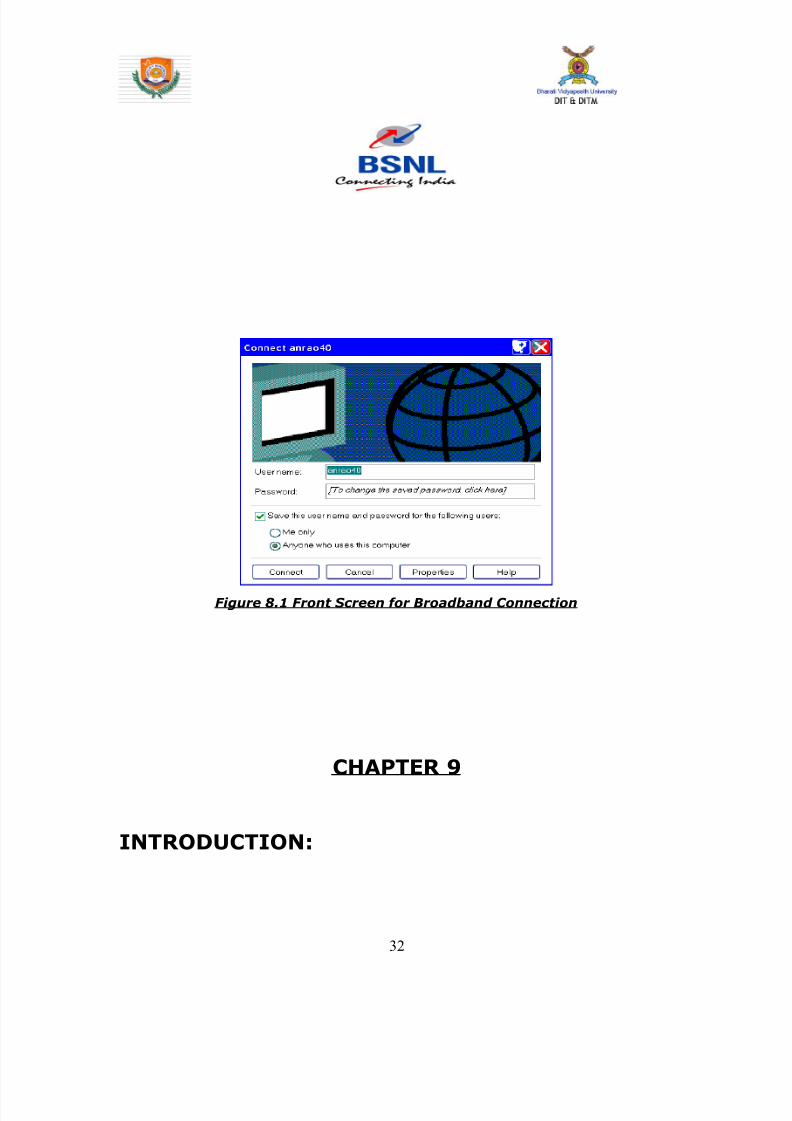
8142019 Dipti Report
httpslidepdfcomreaderfulldipti-report 3262
Figure 81 Front Screen for Broadband Connection
CHAPTER 9
INTRODUCTION
32
8142019 Dipti Report
httpslidepdfcomreaderfulldipti-report 3362
GSM
GSM (Global System for Mobile communications) is an open digital
cellular technology used for transmitting mobile voice and data
services GSM differs from first generation wireless systems in that it
uses digital technology and time division multiple access transmission
methods
GSM is a circuit-switched system that divides each 200 kHz channel
into eight 25 kHz time-slots GSM operates in the 900MHz and 18GHz
bands in Europe and the 19GHz and 850MHz bands in the US The
850MHz band is also used for GSM and 3GSM in Australia Canada and
many South American countries
GSM supports data transfer speeds of up to 96 kbits allowing the
transmission of basic data services such as SMS (Short Message
Service) Another major benefit is its international roaming capability
allowing users to access the same services when travelling abroad as
at home This gives consumers seamless and same number
connectivity in more than 210 countries GSM satellite roaming has
also extended service access to areas where terrestrial coverage is not
available
91 GSM Interfaces -
33
8142019 Dipti Report
httpslidepdfcomreaderfulldipti-report 3462
II A - Interface
This is the interface within the GSM network architecture between the
BSS (Base Station Subsystem) and an MSC (Mobile Switching Centre)
The interface supports standard 64Kbps channels for signalling and
traffic The primary protocols on this interface are DTAP (Direct
Transfer Application Part) and BSSMAP (Base Station Subsystem
Management Application Part)
Figure 91 A - Interface
III Abis ndash Interface
The interface within the GSM architecture between the BTS (Base Transceiver
Station) and BSC (Base Station Controller) This interface is usually configured
using a 16Kbps slot structure
34
8142019 Dipti Report
httpslidepdfcomreaderfulldipti-report 3562
Figure 92 Abis Interface
Air ndash Interface (UM Interface)Interface between MS to BTS
B ndash Interface
Interface between MSC to VLR
C- Interface
Interface between HLR to MSC
D-Interface
Interface between HLR to VLR
35
8142019 Dipti Report
httpslidepdfcomreaderfulldipti-report 3662
E-Interface
Interface between MSC to MSC
F-Interface
Interface between MSC to EIR
G-InterfaceInterface between VLR to VLR
H-Interface
Interface between HLR to AUC
Figure 93 Mobile Tower having Antenna
36
8142019 Dipti Report
httpslidepdfcomreaderfulldipti-report 3762
Figure 94 GSM Architecture along with Interfaces
92 Architecture of the GSM network
The GSM network can be divided into four main parts
bull The Mobile Station (MS)
bull The Base Station Subsystem (BSS)
bull The Network and Switching Subsystem (NSS)
bull The Operation and Support Subsystem (OSS)
921 Mobile Station
A Mobile Station consists of two main elements
37
8142019 Dipti Report
httpslidepdfcomreaderfulldipti-report 3862
bull The mobile equipment or terminal
bull The Subscriber Identity Module (SIM)
Figure 95 Mobile Equipment and SIM
The Terminal
There are different types of terminals distinguished principally by their
power and application
bull The `fixed terminals are the ones installed in cars Their
maximum allowed output power is 20 W
bull The GSM portable terminals can also be installed in vehicles
Their maximum allowed output power is 8W
bull The handhels terminals have experienced the biggest success
thanks to thei weight and volume which are continuously
decreasing These terminals can emit up to 2 W The evolution of
technologies allows to decrease the maximum allowed power to
08 W
38
8142019 Dipti Report
httpslidepdfcomreaderfulldipti-report 3962
The SIM
The SIM is a smart card that identifies the terminal By inserting the
SIM card into the terminal the user can have access to all the
subscribed services Without the SIM card the terminal is not
operational
Another advantage of the SIM card is the mobility of the users In fact
the only element that personalizes a terminal is the SIM card
922 The Base Station Subsystem
The BSS connects the Mobile Station and the NSS It is in charge of
the transmission and reception The BSS can be divided into two parts
bull The Base Transceiver Station (BTS) or Base Station
bull The Base Station Controller (BSC)
9221 The Base Transceiver Station
The BTS corresponds to the transceivers and antennas used in
each cell of the network A BTS is usually placed in the center of a cell
Its transmitting power defines the size of a cell Each BTS has between
one and sixteen transceivers depending on the density of users in the
cell
39
8142019 Dipti Report
httpslidepdfcomreaderfulldipti-report 4062
40
8142019 Dipti Report
httpslidepdfcomreaderfulldipti-report 4162
Figure96 Picture of BTS
9222 The Base Station Controller
The BSC controls a group of BTS and manages their radio ressources
A BSC is principally in charge of handovers frequency hopping
exchange functions and control of the radio frequency power levels of
the BTSs
41
8142019 Dipti Report
httpslidepdfcomreaderfulldipti-report 4262
Figure 97 Picture of BSC
42
8142019 Dipti Report
httpslidepdfcomreaderfulldipti-report 4362
923 The Network and Switching Subsystem
Its main role is to manage the communications between the mobile
users and other users such as mobile users ISDN users fixed
telephony users etc It also includes data bases needed in order to
store information about the subscribers and to manage their mobility
The different components of the NSS are described below
92 31 The Mobile services Switching Center (MSC)
It is the central component of the NSS The MSC
performs the switching functions of the network It also provides
connection to other networks
9232 The Gateway Mobile services Switching Center
(GMSC)
A gateway is a node interconnecting two networks The GMSC is the
interface between the mobile cellular network and the PSTN It is in
charge of routing calls from the fixed network towards a GSM user
The GMSC is often implemented in the same machines as the MSC
92 33 Home location register (HLR)
HLR stores information of subscriber belonging to the covering area of
MSC It also stores the current location of these subscribers and the
service to which they have access
43
8142019 Dipti Report
httpslidepdfcomreaderfulldipti-report 4462
9234 Visitor location register (VLR)
VLR contains information from subscriberrsquos HLR necessary in order to
provide the subscribed services to visiting users
VLR is always implemented together with a MSC soothe area under
control of the MSC is also the area under control of the VLR
9235 Authentication center (AUC)
AUC register is used for security purpose It helps to verify the userrsquos
identity
9236 Equipment identity register (EIR )
EIR contains a list of all valid terminals The EIR allows the forbid calls
from stolen or unauthorized terminals
92 37 The GSM Interworking Unit (GIWU)
The GIWU corresponds to an interface to various networks for data
communications During these communications the transmission of
speech and data can be alternated
924 The Operation and Support Subsystem (OSS)
The OSS is connected to the different components of the NSS and to
the BSC in order to control and monitor the GSM system It is also in
charge of controlling the traffic load of the BSS
44
8142019 Dipti Report
httpslidepdfcomreaderfulldipti-report 4562
Figure 98 BLOCK DIAGRAM OF MOBILE TOWER AND
TRANSMISSION
93 The GSM functions
In this paragraph the description of the GSM network is focused on
the differents functions to fulfil by the network and not on its physical
components In GSM five main functions can be defined
bull Transmission
bull Radio Resources management (RR)
bull Mobility Management (MM)
bull Communication Management (CM)
bull Operation Administration and Maintenance (OAM)
45
8142019 Dipti Report
httpslidepdfcomreaderfulldipti-report 4662
94 GSM Frequencies
In principle the GSM system can be implemented in any frequency
band However there are several bands where GSM terminals are or
will shortly be available Furthermore GSM terminals may incorporate
one or more of the GSM frequency bands listed below to facilitate
roaming on a global basis
Frequency Range
GSM400 4504 - 4576 MHz paired with 4604 - 4676
MHz
or
4788 - 486 MHz paired with 4888 - 496 MHz
GSM 850 824 - 849 MHz paired with 869 - 894 MHz
GSM900 880 - 915 MHz paired with 925 - 960 MHz
GSM1800 1710 - 1785 MHz paired with 1805 - 1880 MHz
GSM1900 1850 - 1910 MHz paired with 1930 - 1990 MHz
95 Frequency allocation
Two frequency bands of 25 Mhz each one have been allocated for the
GSM system
bull The band 890-915 Mhz has been allocated for the uplink
direction (transmitting from the mobile station to the base
station)
46
8142019 Dipti Report
httpslidepdfcomreaderfulldipti-report 4762
bull The band 935-960 Mhz has been allocated for the downlink
direction (transmitting from the base station to the mobile
station)
But not all the countries can use the whole GSM frequency bands
This is due principally to military reasons and to the existence of
previous analog systems using part of the two 25 Mhz frequency
bands
Traffic is measured in ERLANG
BSC Capacity is 1min 5000 ERLANG
Now in 3G in respect of BSC MSC
RNC(Radio Network Control) is used
CHAPTER 10
47
8142019 Dipti Report
httpslidepdfcomreaderfulldipti-report 4862
INTRODUCTION
MAIN DISTRIBUTION FRAME (MDF)
The main distribution frame acts as a link between the
exchange indoor and the exchange outdoor It not only
connects the exchange with the subscriber but also protects
the exchange from environmental hazards such as lightning
strike
There are two sides in a MDF -
101 Line side - The line side belongs to the outdoor The
subscriber is connected to the exchange via the MDF In the
line side there are analog connections
This side of the exchange consists of verticals Each vertical
has 100 trans and receive pairs connected to it ie 100
subscribers are connected to the exchange via one vertical
Each vertical corresponds to a particular pillar The line wires
emanating from the verticals are connected to a cabinet
from where it is taken to a pillar which then is connected to
48
8142019 Dipti Report
httpslidepdfcomreaderfulldipti-report 4962
a distribution pole (DP) From here the lines are distributed
to the subscribers
For line testing on the line side the dial tone is tested on the
vertical first If it is found to be ok then the testing is carried
forward to the cabinet From here line wires are carried
forward in a cluster of around 100 pairs to the pillar A pillar
is usually located in the central part of an area where the
pillar is established so that distribution is convenient and
less expensive One distribution pole is set up to provide
connection to around 15 to 20 homes From here the
subscribers are directly connected
102 Exchange side - Exchange side belongs to the
exchange On the exchange side of the MDF the connections
are DigitalThe connection between the
exchange and the subscriber is made in various stages On
the exchange side the MDF is directly connected to the DLU
in the SN (Switching Network) In the MDF the two sides
49
8142019 Dipti Report
httpslidepdfcomreaderfulldipti-report 5062
are connected through a jumper wire The line testing for
the exchange is done first here using a dial tone checker
For rectifying errors each subscriber is assigned an
Equipment Number (NE) This number is the identification
mark of the subscriber for the exchange It represents the
location in the DLU from where the connection is provided
The DLU is then connected to the LTG (Line Trunk Groups)
from here the switching network is connected
CHAPTER 11
50
8142019 Dipti Report
httpslidepdfcomreaderfulldipti-report 5162
INTRODUCTION
THE POWER PLANT
Power Plant is the main part of an Exchange It provide uninterrupted
power to the exchange continuously it also plays the role of converting
AC power to DC power
The arrangement made has one active and two standby systems for
supplying power This makes the system extremely reliable even in the
areas with acute power shortage Options like maintenance free
batteries (VRLA) also make it cost effective
There are three supply options in the power plant
bull The AC mains
bull The Value Regulated Lead Acid battery set
bull The engine alternator
111 The AC Mains
The exchange requires a constant supply voltage of 48V (DC) in the
running condition So the voltage obtained from which is 66 KV needs
51
8142019 Dipti Report
httpslidepdfcomreaderfulldipti-report 5262
to be stepped down and rectified to DC voltage This function is
performed by the float rectifier unit
112 The Battery Set
There are two sets of VRLA batteries which are maintenance free
batteries Each set is capable of providing the required 48V DC supply
and have a capacity of 4000 AH (Ampere Hour) They are named as
set A and set B One set is active while the other set is available for
standby In case AC mains power is on both the sets of batteries get
charged As soon as there is a power cut the load gets switched over
to the battery set and one of the sets gets active while the other is
available for standby But even this source cannot be trusted for very
long durations as each set is capable of sustaining the load only for
about 3 hours So we need another alternative to provide a fool proof
system This calls for the use of the engine alternator
1113 The Engine Alternator
Usually the battery set is always kept for standby operation In case
there is a power cut the battery set operates hardly for 5 to 10
minutes which is the time taken for the alternator to start
There are also two sets of generators which are rated as follows
bull 66 KV415V voltage rating with moisture absorber
bull 200 KVA power rating
52
8142019 Dipti Report
httpslidepdfcomreaderfulldipti-report 5362
CHAPTER 12
INTRODUCTION
OPERATION AND MAINTENANCE TERMINAL
On the basis of Operation and maintenance terminal Function it has
been grouped into following categories
121 OPERATING FUNCTIONS
1 Charging function
2 Continuous connectivity management
3 Memory management of Translator
122 SUPERVISION FUNCTIONS
1 Circuit tests
2 Line and subscriber set tests
3 Load and traffic observation
123 MAINTENANCE FUNCTIONS
1 Maintenance of exchange control unit memories
2 Fault location and trouble-shooting aid function
3 Telephone equipment position
53
8142019 Dipti Report
httpslidepdfcomreaderfulldipti-report 5462
CHAPTER 13
INTRODUCTION
PULSE CODE MODULATION
PCM is a process which converts a continuous analog signal into digital
signals It is a Multichannel transmission technique that explores the
advantage of digital transmission over analog transmission It only
realizes the advantages of improved transmission limits greater noise
immunity lesser distortion of dial pulses but also economy
Converting continuous analog signal into digital signals is
carried out in three stages-
131 Sampling- Sampling is a periodical
measurement of the value of the analog signal A sampled
data contains all the information of the signal if the
sampling frequency is at least twice the highest frequency
of the signal to be sampled As the signals in telephony are
band limited to 300-3400Hz a sampling are frequency of
8000Hz ie every 125 micro seconds is sufficient
54
8142019 Dipti Report
httpslidepdfcomreaderfulldipti-report 5562
132 Quantizing - representation of their amplitude is forced to
take certain value To ensure that the ratio between signal amplitude
and errors introduced by quantized and encoded (companding) law is
applied
133 Encoding - PAM signals are quantized and encoded into 8
bit symmetrical binary code and transmitted on line during the time
slot allotted to that channel as PCM signals
At the receive side these PCM signals are decoded into PAM
signals and smoothed out by passing through low-pass filters to filters
to get back originals signals
This PCM system can support 30 simultaneous telephone conversation
and optionally 8 telegraphteleprinter channels on one line Individual
channels have a transmission speed of 64 Kbitss and the total
transmission rate for all 32 channels in the system is 2048 Kbitss
55
8142019 Dipti Report
httpslidepdfcomreaderfulldipti-report 5662
CHAPTER 14
INTRODUCTION
SWITCHING
There are two types of switching namely CIRCUIT Switching and
PACKET Switching
141 CIRCUIT SWITCHING - A circuit switching network is onethat establishes a dedicated circuit between nodes and terminals
before the users may communicate Each circuit that is dedicated
cannot be used by other callers until the circuit is released and a new
connection is set up Even if no actual communication is taking place in
a dedicated circuit then that channel still remains unavailable to other
users Channels that are available for new calls to be set up are said to
be idle Early telephone exchanges are a suitable example of circuitswitching
142 PACKET SWITCHING - Packet switching is a
communications paradigm in which packets are routed between nodes
over data links shared with other traffic This contrasts with the other
56
8142019 Dipti Report
httpslidepdfcomreaderfulldipti-report 5762
principal paradigm circuit switching which sets up a dedicated
connection between the two nodes for their exclusive use for the
duration of the communication Packet switching is used to optimize
the use of the channel capacity available in a network to minimize the
transmission latency (ie the time it takes for data to pass across the
network) and to increase robustness of communication
143 Circuit Switching vs Packet
Switching
In principle circuit switching and packet switching both are used in
high-capacity networks In circuit-switched networks network
resources are static set in ldquocopperrdquo if you will from the sender to
receiver before the start of the transfer thus creating a ldquocircuitrdquo The
resources remain dedicated to the circuit during the entire transfer and
the entire message follows the same path In packet-switched
networks the message is broken into packets each of which can take
a different route to the destination where the packets are recompiled
into the original message Circuit switching contrasts with packet
switching which splits traffic data (for instance digital representation
of sound or computer data) into chunks called packets that are
routed over a shared network Packet switching networks do not
require a circuit to be established and allow many pairs of nodes to
communicate almost simultaneously over the same channel Each
57
8142019 Dipti Report
httpslidepdfcomreaderfulldipti-report 5862
packet is individually addressed precluding the need for a dedicated
path to help the packet find its way to its destination
CHAPTER 15
CONCLUSION
This Practical Training has given me an opportunity to know about various
technologies working behind in todayrsquos advanced world of telecommunication
All those that we read in our Book only theoretically by this training I observe all
those practically I come across different units in telecom exchange like
E10BOCBEWSD Mobile (GSM) BSC and BTS MDF and Power Plant
and Broadband I not only watch those equipment but also know about those
there working there functions and also how by work to provide us facility of
telecomI am very grateful to those persons who helped directly amp
indirectly in the successful completion of this practical training and this will
surely be fruitful in future
58
8142019 Dipti Report
httpslidepdfcomreaderfulldipti-report 5962
CHAPTER 16
APPENDIX
161 Loading statement of Jamshedpur OCB-283Capacity of the TAXndash22K Loading ndash 5915
Station IC OG Between Total PCM
Arra Nil Nil 30 1
Ambala Nil Nil 30 1
Bangalore Nil Nil 61 2
Bhagalpur Nil Nil 60 2
Chennai Nil Nil 30 1
Cuttack Nil Nil 184 6
Daltengung Nil Nil 30 1
Darbhanga Nil Nil 60 2
Delhi bsnl Nil Nil 122 4Delhi mtnl Nil Nil 91 3
Dhanbad Nil Nil 122 4
Dumka Nil Nil 30 1
Ericson1 Nil Nil 494 16
Ericson2 Ni Nil 122 4
Gaya Nil Nil 61 2
Hajipur Nil Nil 30 1
Hazaribag Nil Nil 91 3
Hyderabad Nil Nil 123 4
Kolkata Nil Nil 246 8
Kharagpur Nil Nil 91 3
Katihar Nil Nil 30 1
Lucknow Nil Nil 90 3
Mumbai bsnl Nil Nil 61 2
Mumbai mtnl Nil Nil 62 2
59
8142019 Dipti Report
httpslidepdfcomreaderfulldipti-report 6062
Munger Nil Nil 30 1
Muzafferpur Nil Nil 61 2
Nortel Nil Nil 587 19
Purulia Nil Nil 61 2
Patna Nil Nil 151 5
Patliputr Nil Nil 122 8
Raurkela Nil Nil 91 3
Ranchi 15 45 680 24
Sasaram Nil Nil 30 1
Saharsa Nil Nil 30 1Sakla Nil Nil 153 5
Sambalpur Nil Nil 30 1
Tarang Nil Nil 154 5
Baripada Nil Nil 60 2
MSCA Nil Nil 309 10
Msc bokaro Nil Nil 618 20
Total 15 45 5518 182
162 OCB ndash 283 MAIN TELEPHONE EXCHANGES
EXCHANGE CAPACITY PCM
Main Exchange 12k -
Rsu Telco 11256 15
Rsu Adityapur 3k -
Rsu Sidhgora 4k 12
Rsu Mani fit 4256k 11
Rsu Govindpur 2k 10
Rsu Tatanagar 4256k 14
Rsu Parsudih 4k 11
Dlcjsr 6rt -Dlc Parsudih 2rt -
DlcTelco 1rt -
RsuKharkai 1k -
Ghatsila 6585 12
Bahragora 6594 3
Chaibasa 6582 12
60
8142019 Dipti Report
httpslidepdfcomreaderfulldipti-report 6162
Chakardharpur 6587 5
Manoharpur 6593 2
Saraikela 6597 7
Chandil 6591 -
Jhinkpani 6589 -
Jagannathpur 6588 -
Giriburu 6596 4
Nowamundi 6596 5
Kharzwara 6583 -
163 PHONE CODES AND THEIR EXCHANGE CODE
61
PHONE CODE EXCHANGE
2758 JSR
2756 JSR
2421 JSR
243 JSR
244 JSR
248 JSR
222 JSR223 JSR
265 SNK
240 ADR
220 ADR
2370-3 ADR
2380-3 ADR
2386-87 GMR
246 amp 236 MNG
29 7 DIGIT WJSR
2270 GVP2277 GVP
2290-95 TAT
2296 PSD
230-231 KDM
234 GOL
226228 TLC
221 SDG
232 LIC
2249 KHL
8142019 Dipti Report
httpslidepdfcomreaderfulldipti-report 6262
8142019 Dipti Report
httpslidepdfcomreaderfulldipti-report 3362
GSM
GSM (Global System for Mobile communications) is an open digital
cellular technology used for transmitting mobile voice and data
services GSM differs from first generation wireless systems in that it
uses digital technology and time division multiple access transmission
methods
GSM is a circuit-switched system that divides each 200 kHz channel
into eight 25 kHz time-slots GSM operates in the 900MHz and 18GHz
bands in Europe and the 19GHz and 850MHz bands in the US The
850MHz band is also used for GSM and 3GSM in Australia Canada and
many South American countries
GSM supports data transfer speeds of up to 96 kbits allowing the
transmission of basic data services such as SMS (Short Message
Service) Another major benefit is its international roaming capability
allowing users to access the same services when travelling abroad as
at home This gives consumers seamless and same number
connectivity in more than 210 countries GSM satellite roaming has
also extended service access to areas where terrestrial coverage is not
available
91 GSM Interfaces -
33
8142019 Dipti Report
httpslidepdfcomreaderfulldipti-report 3462
II A - Interface
This is the interface within the GSM network architecture between the
BSS (Base Station Subsystem) and an MSC (Mobile Switching Centre)
The interface supports standard 64Kbps channels for signalling and
traffic The primary protocols on this interface are DTAP (Direct
Transfer Application Part) and BSSMAP (Base Station Subsystem
Management Application Part)
Figure 91 A - Interface
III Abis ndash Interface
The interface within the GSM architecture between the BTS (Base Transceiver
Station) and BSC (Base Station Controller) This interface is usually configured
using a 16Kbps slot structure
34
8142019 Dipti Report
httpslidepdfcomreaderfulldipti-report 3562
Figure 92 Abis Interface
Air ndash Interface (UM Interface)Interface between MS to BTS
B ndash Interface
Interface between MSC to VLR
C- Interface
Interface between HLR to MSC
D-Interface
Interface between HLR to VLR
35
8142019 Dipti Report
httpslidepdfcomreaderfulldipti-report 3662
E-Interface
Interface between MSC to MSC
F-Interface
Interface between MSC to EIR
G-InterfaceInterface between VLR to VLR
H-Interface
Interface between HLR to AUC
Figure 93 Mobile Tower having Antenna
36
8142019 Dipti Report
httpslidepdfcomreaderfulldipti-report 3762
Figure 94 GSM Architecture along with Interfaces
92 Architecture of the GSM network
The GSM network can be divided into four main parts
bull The Mobile Station (MS)
bull The Base Station Subsystem (BSS)
bull The Network and Switching Subsystem (NSS)
bull The Operation and Support Subsystem (OSS)
921 Mobile Station
A Mobile Station consists of two main elements
37
8142019 Dipti Report
httpslidepdfcomreaderfulldipti-report 3862
bull The mobile equipment or terminal
bull The Subscriber Identity Module (SIM)
Figure 95 Mobile Equipment and SIM
The Terminal
There are different types of terminals distinguished principally by their
power and application
bull The `fixed terminals are the ones installed in cars Their
maximum allowed output power is 20 W
bull The GSM portable terminals can also be installed in vehicles
Their maximum allowed output power is 8W
bull The handhels terminals have experienced the biggest success
thanks to thei weight and volume which are continuously
decreasing These terminals can emit up to 2 W The evolution of
technologies allows to decrease the maximum allowed power to
08 W
38
8142019 Dipti Report
httpslidepdfcomreaderfulldipti-report 3962
The SIM
The SIM is a smart card that identifies the terminal By inserting the
SIM card into the terminal the user can have access to all the
subscribed services Without the SIM card the terminal is not
operational
Another advantage of the SIM card is the mobility of the users In fact
the only element that personalizes a terminal is the SIM card
922 The Base Station Subsystem
The BSS connects the Mobile Station and the NSS It is in charge of
the transmission and reception The BSS can be divided into two parts
bull The Base Transceiver Station (BTS) or Base Station
bull The Base Station Controller (BSC)
9221 The Base Transceiver Station
The BTS corresponds to the transceivers and antennas used in
each cell of the network A BTS is usually placed in the center of a cell
Its transmitting power defines the size of a cell Each BTS has between
one and sixteen transceivers depending on the density of users in the
cell
39
8142019 Dipti Report
httpslidepdfcomreaderfulldipti-report 4062
40
8142019 Dipti Report
httpslidepdfcomreaderfulldipti-report 4162
Figure96 Picture of BTS
9222 The Base Station Controller
The BSC controls a group of BTS and manages their radio ressources
A BSC is principally in charge of handovers frequency hopping
exchange functions and control of the radio frequency power levels of
the BTSs
41
8142019 Dipti Report
httpslidepdfcomreaderfulldipti-report 4262
Figure 97 Picture of BSC
42
8142019 Dipti Report
httpslidepdfcomreaderfulldipti-report 4362
923 The Network and Switching Subsystem
Its main role is to manage the communications between the mobile
users and other users such as mobile users ISDN users fixed
telephony users etc It also includes data bases needed in order to
store information about the subscribers and to manage their mobility
The different components of the NSS are described below
92 31 The Mobile services Switching Center (MSC)
It is the central component of the NSS The MSC
performs the switching functions of the network It also provides
connection to other networks
9232 The Gateway Mobile services Switching Center
(GMSC)
A gateway is a node interconnecting two networks The GMSC is the
interface between the mobile cellular network and the PSTN It is in
charge of routing calls from the fixed network towards a GSM user
The GMSC is often implemented in the same machines as the MSC
92 33 Home location register (HLR)
HLR stores information of subscriber belonging to the covering area of
MSC It also stores the current location of these subscribers and the
service to which they have access
43
8142019 Dipti Report
httpslidepdfcomreaderfulldipti-report 4462
9234 Visitor location register (VLR)
VLR contains information from subscriberrsquos HLR necessary in order to
provide the subscribed services to visiting users
VLR is always implemented together with a MSC soothe area under
control of the MSC is also the area under control of the VLR
9235 Authentication center (AUC)
AUC register is used for security purpose It helps to verify the userrsquos
identity
9236 Equipment identity register (EIR )
EIR contains a list of all valid terminals The EIR allows the forbid calls
from stolen or unauthorized terminals
92 37 The GSM Interworking Unit (GIWU)
The GIWU corresponds to an interface to various networks for data
communications During these communications the transmission of
speech and data can be alternated
924 The Operation and Support Subsystem (OSS)
The OSS is connected to the different components of the NSS and to
the BSC in order to control and monitor the GSM system It is also in
charge of controlling the traffic load of the BSS
44
8142019 Dipti Report
httpslidepdfcomreaderfulldipti-report 4562
Figure 98 BLOCK DIAGRAM OF MOBILE TOWER AND
TRANSMISSION
93 The GSM functions
In this paragraph the description of the GSM network is focused on
the differents functions to fulfil by the network and not on its physical
components In GSM five main functions can be defined
bull Transmission
bull Radio Resources management (RR)
bull Mobility Management (MM)
bull Communication Management (CM)
bull Operation Administration and Maintenance (OAM)
45
8142019 Dipti Report
httpslidepdfcomreaderfulldipti-report 4662
94 GSM Frequencies
In principle the GSM system can be implemented in any frequency
band However there are several bands where GSM terminals are or
will shortly be available Furthermore GSM terminals may incorporate
one or more of the GSM frequency bands listed below to facilitate
roaming on a global basis
Frequency Range
GSM400 4504 - 4576 MHz paired with 4604 - 4676
MHz
or
4788 - 486 MHz paired with 4888 - 496 MHz
GSM 850 824 - 849 MHz paired with 869 - 894 MHz
GSM900 880 - 915 MHz paired with 925 - 960 MHz
GSM1800 1710 - 1785 MHz paired with 1805 - 1880 MHz
GSM1900 1850 - 1910 MHz paired with 1930 - 1990 MHz
95 Frequency allocation
Two frequency bands of 25 Mhz each one have been allocated for the
GSM system
bull The band 890-915 Mhz has been allocated for the uplink
direction (transmitting from the mobile station to the base
station)
46
8142019 Dipti Report
httpslidepdfcomreaderfulldipti-report 4762
bull The band 935-960 Mhz has been allocated for the downlink
direction (transmitting from the base station to the mobile
station)
But not all the countries can use the whole GSM frequency bands
This is due principally to military reasons and to the existence of
previous analog systems using part of the two 25 Mhz frequency
bands
Traffic is measured in ERLANG
BSC Capacity is 1min 5000 ERLANG
Now in 3G in respect of BSC MSC
RNC(Radio Network Control) is used
CHAPTER 10
47
8142019 Dipti Report
httpslidepdfcomreaderfulldipti-report 4862
INTRODUCTION
MAIN DISTRIBUTION FRAME (MDF)
The main distribution frame acts as a link between the
exchange indoor and the exchange outdoor It not only
connects the exchange with the subscriber but also protects
the exchange from environmental hazards such as lightning
strike
There are two sides in a MDF -
101 Line side - The line side belongs to the outdoor The
subscriber is connected to the exchange via the MDF In the
line side there are analog connections
This side of the exchange consists of verticals Each vertical
has 100 trans and receive pairs connected to it ie 100
subscribers are connected to the exchange via one vertical
Each vertical corresponds to a particular pillar The line wires
emanating from the verticals are connected to a cabinet
from where it is taken to a pillar which then is connected to
48
8142019 Dipti Report
httpslidepdfcomreaderfulldipti-report 4962
a distribution pole (DP) From here the lines are distributed
to the subscribers
For line testing on the line side the dial tone is tested on the
vertical first If it is found to be ok then the testing is carried
forward to the cabinet From here line wires are carried
forward in a cluster of around 100 pairs to the pillar A pillar
is usually located in the central part of an area where the
pillar is established so that distribution is convenient and
less expensive One distribution pole is set up to provide
connection to around 15 to 20 homes From here the
subscribers are directly connected
102 Exchange side - Exchange side belongs to the
exchange On the exchange side of the MDF the connections
are DigitalThe connection between the
exchange and the subscriber is made in various stages On
the exchange side the MDF is directly connected to the DLU
in the SN (Switching Network) In the MDF the two sides
49
8142019 Dipti Report
httpslidepdfcomreaderfulldipti-report 5062
are connected through a jumper wire The line testing for
the exchange is done first here using a dial tone checker
For rectifying errors each subscriber is assigned an
Equipment Number (NE) This number is the identification
mark of the subscriber for the exchange It represents the
location in the DLU from where the connection is provided
The DLU is then connected to the LTG (Line Trunk Groups)
from here the switching network is connected
CHAPTER 11
50
8142019 Dipti Report
httpslidepdfcomreaderfulldipti-report 5162
INTRODUCTION
THE POWER PLANT
Power Plant is the main part of an Exchange It provide uninterrupted
power to the exchange continuously it also plays the role of converting
AC power to DC power
The arrangement made has one active and two standby systems for
supplying power This makes the system extremely reliable even in the
areas with acute power shortage Options like maintenance free
batteries (VRLA) also make it cost effective
There are three supply options in the power plant
bull The AC mains
bull The Value Regulated Lead Acid battery set
bull The engine alternator
111 The AC Mains
The exchange requires a constant supply voltage of 48V (DC) in the
running condition So the voltage obtained from which is 66 KV needs
51
8142019 Dipti Report
httpslidepdfcomreaderfulldipti-report 5262
to be stepped down and rectified to DC voltage This function is
performed by the float rectifier unit
112 The Battery Set
There are two sets of VRLA batteries which are maintenance free
batteries Each set is capable of providing the required 48V DC supply
and have a capacity of 4000 AH (Ampere Hour) They are named as
set A and set B One set is active while the other set is available for
standby In case AC mains power is on both the sets of batteries get
charged As soon as there is a power cut the load gets switched over
to the battery set and one of the sets gets active while the other is
available for standby But even this source cannot be trusted for very
long durations as each set is capable of sustaining the load only for
about 3 hours So we need another alternative to provide a fool proof
system This calls for the use of the engine alternator
1113 The Engine Alternator
Usually the battery set is always kept for standby operation In case
there is a power cut the battery set operates hardly for 5 to 10
minutes which is the time taken for the alternator to start
There are also two sets of generators which are rated as follows
bull 66 KV415V voltage rating with moisture absorber
bull 200 KVA power rating
52
8142019 Dipti Report
httpslidepdfcomreaderfulldipti-report 5362
CHAPTER 12
INTRODUCTION
OPERATION AND MAINTENANCE TERMINAL
On the basis of Operation and maintenance terminal Function it has
been grouped into following categories
121 OPERATING FUNCTIONS
1 Charging function
2 Continuous connectivity management
3 Memory management of Translator
122 SUPERVISION FUNCTIONS
1 Circuit tests
2 Line and subscriber set tests
3 Load and traffic observation
123 MAINTENANCE FUNCTIONS
1 Maintenance of exchange control unit memories
2 Fault location and trouble-shooting aid function
3 Telephone equipment position
53
8142019 Dipti Report
httpslidepdfcomreaderfulldipti-report 5462
CHAPTER 13
INTRODUCTION
PULSE CODE MODULATION
PCM is a process which converts a continuous analog signal into digital
signals It is a Multichannel transmission technique that explores the
advantage of digital transmission over analog transmission It only
realizes the advantages of improved transmission limits greater noise
immunity lesser distortion of dial pulses but also economy
Converting continuous analog signal into digital signals is
carried out in three stages-
131 Sampling- Sampling is a periodical
measurement of the value of the analog signal A sampled
data contains all the information of the signal if the
sampling frequency is at least twice the highest frequency
of the signal to be sampled As the signals in telephony are
band limited to 300-3400Hz a sampling are frequency of
8000Hz ie every 125 micro seconds is sufficient
54
8142019 Dipti Report
httpslidepdfcomreaderfulldipti-report 5562
132 Quantizing - representation of their amplitude is forced to
take certain value To ensure that the ratio between signal amplitude
and errors introduced by quantized and encoded (companding) law is
applied
133 Encoding - PAM signals are quantized and encoded into 8
bit symmetrical binary code and transmitted on line during the time
slot allotted to that channel as PCM signals
At the receive side these PCM signals are decoded into PAM
signals and smoothed out by passing through low-pass filters to filters
to get back originals signals
This PCM system can support 30 simultaneous telephone conversation
and optionally 8 telegraphteleprinter channels on one line Individual
channels have a transmission speed of 64 Kbitss and the total
transmission rate for all 32 channels in the system is 2048 Kbitss
55
8142019 Dipti Report
httpslidepdfcomreaderfulldipti-report 5662
CHAPTER 14
INTRODUCTION
SWITCHING
There are two types of switching namely CIRCUIT Switching and
PACKET Switching
141 CIRCUIT SWITCHING - A circuit switching network is onethat establishes a dedicated circuit between nodes and terminals
before the users may communicate Each circuit that is dedicated
cannot be used by other callers until the circuit is released and a new
connection is set up Even if no actual communication is taking place in
a dedicated circuit then that channel still remains unavailable to other
users Channels that are available for new calls to be set up are said to
be idle Early telephone exchanges are a suitable example of circuitswitching
142 PACKET SWITCHING - Packet switching is a
communications paradigm in which packets are routed between nodes
over data links shared with other traffic This contrasts with the other
56
8142019 Dipti Report
httpslidepdfcomreaderfulldipti-report 5762
principal paradigm circuit switching which sets up a dedicated
connection between the two nodes for their exclusive use for the
duration of the communication Packet switching is used to optimize
the use of the channel capacity available in a network to minimize the
transmission latency (ie the time it takes for data to pass across the
network) and to increase robustness of communication
143 Circuit Switching vs Packet
Switching
In principle circuit switching and packet switching both are used in
high-capacity networks In circuit-switched networks network
resources are static set in ldquocopperrdquo if you will from the sender to
receiver before the start of the transfer thus creating a ldquocircuitrdquo The
resources remain dedicated to the circuit during the entire transfer and
the entire message follows the same path In packet-switched
networks the message is broken into packets each of which can take
a different route to the destination where the packets are recompiled
into the original message Circuit switching contrasts with packet
switching which splits traffic data (for instance digital representation
of sound or computer data) into chunks called packets that are
routed over a shared network Packet switching networks do not
require a circuit to be established and allow many pairs of nodes to
communicate almost simultaneously over the same channel Each
57
8142019 Dipti Report
httpslidepdfcomreaderfulldipti-report 5862
packet is individually addressed precluding the need for a dedicated
path to help the packet find its way to its destination
CHAPTER 15
CONCLUSION
This Practical Training has given me an opportunity to know about various
technologies working behind in todayrsquos advanced world of telecommunication
All those that we read in our Book only theoretically by this training I observe all
those practically I come across different units in telecom exchange like
E10BOCBEWSD Mobile (GSM) BSC and BTS MDF and Power Plant
and Broadband I not only watch those equipment but also know about those
there working there functions and also how by work to provide us facility of
telecomI am very grateful to those persons who helped directly amp
indirectly in the successful completion of this practical training and this will
surely be fruitful in future
58
8142019 Dipti Report
httpslidepdfcomreaderfulldipti-report 5962
CHAPTER 16
APPENDIX
161 Loading statement of Jamshedpur OCB-283Capacity of the TAXndash22K Loading ndash 5915
Station IC OG Between Total PCM
Arra Nil Nil 30 1
Ambala Nil Nil 30 1
Bangalore Nil Nil 61 2
Bhagalpur Nil Nil 60 2
Chennai Nil Nil 30 1
Cuttack Nil Nil 184 6
Daltengung Nil Nil 30 1
Darbhanga Nil Nil 60 2
Delhi bsnl Nil Nil 122 4Delhi mtnl Nil Nil 91 3
Dhanbad Nil Nil 122 4
Dumka Nil Nil 30 1
Ericson1 Nil Nil 494 16
Ericson2 Ni Nil 122 4
Gaya Nil Nil 61 2
Hajipur Nil Nil 30 1
Hazaribag Nil Nil 91 3
Hyderabad Nil Nil 123 4
Kolkata Nil Nil 246 8
Kharagpur Nil Nil 91 3
Katihar Nil Nil 30 1
Lucknow Nil Nil 90 3
Mumbai bsnl Nil Nil 61 2
Mumbai mtnl Nil Nil 62 2
59
8142019 Dipti Report
httpslidepdfcomreaderfulldipti-report 6062
Munger Nil Nil 30 1
Muzafferpur Nil Nil 61 2
Nortel Nil Nil 587 19
Purulia Nil Nil 61 2
Patna Nil Nil 151 5
Patliputr Nil Nil 122 8
Raurkela Nil Nil 91 3
Ranchi 15 45 680 24
Sasaram Nil Nil 30 1
Saharsa Nil Nil 30 1Sakla Nil Nil 153 5
Sambalpur Nil Nil 30 1
Tarang Nil Nil 154 5
Baripada Nil Nil 60 2
MSCA Nil Nil 309 10
Msc bokaro Nil Nil 618 20
Total 15 45 5518 182
162 OCB ndash 283 MAIN TELEPHONE EXCHANGES
EXCHANGE CAPACITY PCM
Main Exchange 12k -
Rsu Telco 11256 15
Rsu Adityapur 3k -
Rsu Sidhgora 4k 12
Rsu Mani fit 4256k 11
Rsu Govindpur 2k 10
Rsu Tatanagar 4256k 14
Rsu Parsudih 4k 11
Dlcjsr 6rt -Dlc Parsudih 2rt -
DlcTelco 1rt -
RsuKharkai 1k -
Ghatsila 6585 12
Bahragora 6594 3
Chaibasa 6582 12
60
8142019 Dipti Report
httpslidepdfcomreaderfulldipti-report 6162
Chakardharpur 6587 5
Manoharpur 6593 2
Saraikela 6597 7
Chandil 6591 -
Jhinkpani 6589 -
Jagannathpur 6588 -
Giriburu 6596 4
Nowamundi 6596 5
Kharzwara 6583 -
163 PHONE CODES AND THEIR EXCHANGE CODE
61
PHONE CODE EXCHANGE
2758 JSR
2756 JSR
2421 JSR
243 JSR
244 JSR
248 JSR
222 JSR223 JSR
265 SNK
240 ADR
220 ADR
2370-3 ADR
2380-3 ADR
2386-87 GMR
246 amp 236 MNG
29 7 DIGIT WJSR
2270 GVP2277 GVP
2290-95 TAT
2296 PSD
230-231 KDM
234 GOL
226228 TLC
221 SDG
232 LIC
2249 KHL
8142019 Dipti Report
httpslidepdfcomreaderfulldipti-report 6262

8142019 Dipti Report
httpslidepdfcomreaderfulldipti-report 3562
Figure 92 Abis Interface
Air ndash Interface (UM Interface)Interface between MS to BTS
B ndash Interface
Interface between MSC to VLR
C- Interface
Interface between HLR to MSC
D-Interface
Interface between HLR to VLR
35
8142019 Dipti Report
httpslidepdfcomreaderfulldipti-report 3662
E-Interface
Interface between MSC to MSC
F-Interface
Interface between MSC to EIR
G-InterfaceInterface between VLR to VLR
H-Interface
Interface between HLR to AUC
Figure 93 Mobile Tower having Antenna
36
8142019 Dipti Report
httpslidepdfcomreaderfulldipti-report 3762
Figure 94 GSM Architecture along with Interfaces
92 Architecture of the GSM network
The GSM network can be divided into four main parts
bull The Mobile Station (MS)
bull The Base Station Subsystem (BSS)
bull The Network and Switching Subsystem (NSS)
bull The Operation and Support Subsystem (OSS)
921 Mobile Station
A Mobile Station consists of two main elements
37
8142019 Dipti Report
httpslidepdfcomreaderfulldipti-report 3862
bull The mobile equipment or terminal
bull The Subscriber Identity Module (SIM)
Figure 95 Mobile Equipment and SIM
The Terminal
There are different types of terminals distinguished principally by their
power and application
bull The `fixed terminals are the ones installed in cars Their
maximum allowed output power is 20 W
bull The GSM portable terminals can also be installed in vehicles
Their maximum allowed output power is 8W
bull The handhels terminals have experienced the biggest success
thanks to thei weight and volume which are continuously
decreasing These terminals can emit up to 2 W The evolution of
technologies allows to decrease the maximum allowed power to
08 W
38
8142019 Dipti Report
httpslidepdfcomreaderfulldipti-report 3962
The SIM
The SIM is a smart card that identifies the terminal By inserting the
SIM card into the terminal the user can have access to all the
subscribed services Without the SIM card the terminal is not
operational
Another advantage of the SIM card is the mobility of the users In fact
the only element that personalizes a terminal is the SIM card
922 The Base Station Subsystem
The BSS connects the Mobile Station and the NSS It is in charge of
the transmission and reception The BSS can be divided into two parts
bull The Base Transceiver Station (BTS) or Base Station
bull The Base Station Controller (BSC)
9221 The Base Transceiver Station
The BTS corresponds to the transceivers and antennas used in
each cell of the network A BTS is usually placed in the center of a cell
Its transmitting power defines the size of a cell Each BTS has between
one and sixteen transceivers depending on the density of users in the
cell
39
8142019 Dipti Report
httpslidepdfcomreaderfulldipti-report 4062
40
8142019 Dipti Report
httpslidepdfcomreaderfulldipti-report 4162
Figure96 Picture of BTS
9222 The Base Station Controller
The BSC controls a group of BTS and manages their radio ressources
A BSC is principally in charge of handovers frequency hopping
exchange functions and control of the radio frequency power levels of
the BTSs
41
8142019 Dipti Report
httpslidepdfcomreaderfulldipti-report 4262
Figure 97 Picture of BSC
42
8142019 Dipti Report
httpslidepdfcomreaderfulldipti-report 4362
923 The Network and Switching Subsystem
Its main role is to manage the communications between the mobile
users and other users such as mobile users ISDN users fixed
telephony users etc It also includes data bases needed in order to
store information about the subscribers and to manage their mobility
The different components of the NSS are described below
92 31 The Mobile services Switching Center (MSC)
It is the central component of the NSS The MSC
performs the switching functions of the network It also provides
connection to other networks
9232 The Gateway Mobile services Switching Center
(GMSC)
A gateway is a node interconnecting two networks The GMSC is the
interface between the mobile cellular network and the PSTN It is in
charge of routing calls from the fixed network towards a GSM user
The GMSC is often implemented in the same machines as the MSC
92 33 Home location register (HLR)
HLR stores information of subscriber belonging to the covering area of
MSC It also stores the current location of these subscribers and the
service to which they have access
43
8142019 Dipti Report
httpslidepdfcomreaderfulldipti-report 4462
9234 Visitor location register (VLR)
VLR contains information from subscriberrsquos HLR necessary in order to
provide the subscribed services to visiting users
VLR is always implemented together with a MSC soothe area under
control of the MSC is also the area under control of the VLR
9235 Authentication center (AUC)
AUC register is used for security purpose It helps to verify the userrsquos
identity
9236 Equipment identity register (EIR )
EIR contains a list of all valid terminals The EIR allows the forbid calls
from stolen or unauthorized terminals
92 37 The GSM Interworking Unit (GIWU)
The GIWU corresponds to an interface to various networks for data
communications During these communications the transmission of
speech and data can be alternated
924 The Operation and Support Subsystem (OSS)
The OSS is connected to the different components of the NSS and to
the BSC in order to control and monitor the GSM system It is also in
charge of controlling the traffic load of the BSS
44
8142019 Dipti Report
httpslidepdfcomreaderfulldipti-report 4562
Figure 98 BLOCK DIAGRAM OF MOBILE TOWER AND
TRANSMISSION
93 The GSM functions
In this paragraph the description of the GSM network is focused on
the differents functions to fulfil by the network and not on its physical
components In GSM five main functions can be defined
bull Transmission
bull Radio Resources management (RR)
bull Mobility Management (MM)
bull Communication Management (CM)
bull Operation Administration and Maintenance (OAM)
45
8142019 Dipti Report
httpslidepdfcomreaderfulldipti-report 4662
94 GSM Frequencies
In principle the GSM system can be implemented in any frequency
band However there are several bands where GSM terminals are or
will shortly be available Furthermore GSM terminals may incorporate
one or more of the GSM frequency bands listed below to facilitate
roaming on a global basis
Frequency Range
GSM400 4504 - 4576 MHz paired with 4604 - 4676
MHz
or
4788 - 486 MHz paired with 4888 - 496 MHz
GSM 850 824 - 849 MHz paired with 869 - 894 MHz
GSM900 880 - 915 MHz paired with 925 - 960 MHz
GSM1800 1710 - 1785 MHz paired with 1805 - 1880 MHz
GSM1900 1850 - 1910 MHz paired with 1930 - 1990 MHz
95 Frequency allocation
Two frequency bands of 25 Mhz each one have been allocated for the
GSM system
bull The band 890-915 Mhz has been allocated for the uplink
direction (transmitting from the mobile station to the base
station)
46
8142019 Dipti Report
httpslidepdfcomreaderfulldipti-report 4762
bull The band 935-960 Mhz has been allocated for the downlink
direction (transmitting from the base station to the mobile
station)
But not all the countries can use the whole GSM frequency bands
This is due principally to military reasons and to the existence of
previous analog systems using part of the two 25 Mhz frequency
bands
Traffic is measured in ERLANG
BSC Capacity is 1min 5000 ERLANG
Now in 3G in respect of BSC MSC
RNC(Radio Network Control) is used
CHAPTER 10
47
8142019 Dipti Report
httpslidepdfcomreaderfulldipti-report 4862
INTRODUCTION
MAIN DISTRIBUTION FRAME (MDF)
The main distribution frame acts as a link between the
exchange indoor and the exchange outdoor It not only
connects the exchange with the subscriber but also protects
the exchange from environmental hazards such as lightning
strike
There are two sides in a MDF -
101 Line side - The line side belongs to the outdoor The
subscriber is connected to the exchange via the MDF In the
line side there are analog connections
This side of the exchange consists of verticals Each vertical
has 100 trans and receive pairs connected to it ie 100
subscribers are connected to the exchange via one vertical
Each vertical corresponds to a particular pillar The line wires
emanating from the verticals are connected to a cabinet
from where it is taken to a pillar which then is connected to
48
8142019 Dipti Report
httpslidepdfcomreaderfulldipti-report 4962
a distribution pole (DP) From here the lines are distributed
to the subscribers
For line testing on the line side the dial tone is tested on the
vertical first If it is found to be ok then the testing is carried
forward to the cabinet From here line wires are carried
forward in a cluster of around 100 pairs to the pillar A pillar
is usually located in the central part of an area where the
pillar is established so that distribution is convenient and
less expensive One distribution pole is set up to provide
connection to around 15 to 20 homes From here the
subscribers are directly connected
102 Exchange side - Exchange side belongs to the
exchange On the exchange side of the MDF the connections
are DigitalThe connection between the
exchange and the subscriber is made in various stages On
the exchange side the MDF is directly connected to the DLU
in the SN (Switching Network) In the MDF the two sides
49
8142019 Dipti Report
httpslidepdfcomreaderfulldipti-report 5062
are connected through a jumper wire The line testing for
the exchange is done first here using a dial tone checker
For rectifying errors each subscriber is assigned an
Equipment Number (NE) This number is the identification
mark of the subscriber for the exchange It represents the
location in the DLU from where the connection is provided
The DLU is then connected to the LTG (Line Trunk Groups)
from here the switching network is connected
CHAPTER 11
50
8142019 Dipti Report
httpslidepdfcomreaderfulldipti-report 5162
INTRODUCTION
THE POWER PLANT
Power Plant is the main part of an Exchange It provide uninterrupted
power to the exchange continuously it also plays the role of converting
AC power to DC power
The arrangement made has one active and two standby systems for
supplying power This makes the system extremely reliable even in the
areas with acute power shortage Options like maintenance free
batteries (VRLA) also make it cost effective
There are three supply options in the power plant
bull The AC mains
bull The Value Regulated Lead Acid battery set
bull The engine alternator
111 The AC Mains
The exchange requires a constant supply voltage of 48V (DC) in the
running condition So the voltage obtained from which is 66 KV needs
51
8142019 Dipti Report
httpslidepdfcomreaderfulldipti-report 5262
to be stepped down and rectified to DC voltage This function is
performed by the float rectifier unit
112 The Battery Set
There are two sets of VRLA batteries which are maintenance free
batteries Each set is capable of providing the required 48V DC supply
and have a capacity of 4000 AH (Ampere Hour) They are named as
set A and set B One set is active while the other set is available for
standby In case AC mains power is on both the sets of batteries get
charged As soon as there is a power cut the load gets switched over
to the battery set and one of the sets gets active while the other is
available for standby But even this source cannot be trusted for very
long durations as each set is capable of sustaining the load only for
about 3 hours So we need another alternative to provide a fool proof
system This calls for the use of the engine alternator
1113 The Engine Alternator
Usually the battery set is always kept for standby operation In case
there is a power cut the battery set operates hardly for 5 to 10
minutes which is the time taken for the alternator to start
There are also two sets of generators which are rated as follows
bull 66 KV415V voltage rating with moisture absorber
bull 200 KVA power rating
52
8142019 Dipti Report
httpslidepdfcomreaderfulldipti-report 5362
CHAPTER 12
INTRODUCTION
OPERATION AND MAINTENANCE TERMINAL
On the basis of Operation and maintenance terminal Function it has
been grouped into following categories
121 OPERATING FUNCTIONS
1 Charging function
2 Continuous connectivity management
3 Memory management of Translator
122 SUPERVISION FUNCTIONS
1 Circuit tests
2 Line and subscriber set tests
3 Load and traffic observation
123 MAINTENANCE FUNCTIONS
1 Maintenance of exchange control unit memories
2 Fault location and trouble-shooting aid function
3 Telephone equipment position
53
8142019 Dipti Report
httpslidepdfcomreaderfulldipti-report 5462
CHAPTER 13
INTRODUCTION
PULSE CODE MODULATION
PCM is a process which converts a continuous analog signal into digital
signals It is a Multichannel transmission technique that explores the
advantage of digital transmission over analog transmission It only
realizes the advantages of improved transmission limits greater noise
immunity lesser distortion of dial pulses but also economy
Converting continuous analog signal into digital signals is
carried out in three stages-
131 Sampling- Sampling is a periodical
measurement of the value of the analog signal A sampled
data contains all the information of the signal if the
sampling frequency is at least twice the highest frequency
of the signal to be sampled As the signals in telephony are
band limited to 300-3400Hz a sampling are frequency of
8000Hz ie every 125 micro seconds is sufficient
54
8142019 Dipti Report
httpslidepdfcomreaderfulldipti-report 5562
132 Quantizing - representation of their amplitude is forced to
take certain value To ensure that the ratio between signal amplitude
and errors introduced by quantized and encoded (companding) law is
applied
133 Encoding - PAM signals are quantized and encoded into 8
bit symmetrical binary code and transmitted on line during the time
slot allotted to that channel as PCM signals
At the receive side these PCM signals are decoded into PAM
signals and smoothed out by passing through low-pass filters to filters
to get back originals signals
This PCM system can support 30 simultaneous telephone conversation
and optionally 8 telegraphteleprinter channels on one line Individual
channels have a transmission speed of 64 Kbitss and the total
transmission rate for all 32 channels in the system is 2048 Kbitss
55
8142019 Dipti Report
httpslidepdfcomreaderfulldipti-report 5662
CHAPTER 14
INTRODUCTION
SWITCHING
There are two types of switching namely CIRCUIT Switching and
PACKET Switching
141 CIRCUIT SWITCHING - A circuit switching network is onethat establishes a dedicated circuit between nodes and terminals
before the users may communicate Each circuit that is dedicated
cannot be used by other callers until the circuit is released and a new
connection is set up Even if no actual communication is taking place in
a dedicated circuit then that channel still remains unavailable to other
users Channels that are available for new calls to be set up are said to
be idle Early telephone exchanges are a suitable example of circuitswitching
142 PACKET SWITCHING - Packet switching is a
communications paradigm in which packets are routed between nodes
over data links shared with other traffic This contrasts with the other
56
8142019 Dipti Report
httpslidepdfcomreaderfulldipti-report 5762
principal paradigm circuit switching which sets up a dedicated
connection between the two nodes for their exclusive use for the
duration of the communication Packet switching is used to optimize
the use of the channel capacity available in a network to minimize the
transmission latency (ie the time it takes for data to pass across the
network) and to increase robustness of communication
143 Circuit Switching vs Packet
Switching
In principle circuit switching and packet switching both are used in
high-capacity networks In circuit-switched networks network
resources are static set in ldquocopperrdquo if you will from the sender to
receiver before the start of the transfer thus creating a ldquocircuitrdquo The
resources remain dedicated to the circuit during the entire transfer and
the entire message follows the same path In packet-switched
networks the message is broken into packets each of which can take
a different route to the destination where the packets are recompiled
into the original message Circuit switching contrasts with packet
switching which splits traffic data (for instance digital representation
of sound or computer data) into chunks called packets that are
routed over a shared network Packet switching networks do not
require a circuit to be established and allow many pairs of nodes to
communicate almost simultaneously over the same channel Each
57
8142019 Dipti Report
httpslidepdfcomreaderfulldipti-report 5862
packet is individually addressed precluding the need for a dedicated
path to help the packet find its way to its destination
CHAPTER 15
CONCLUSION
This Practical Training has given me an opportunity to know about various
technologies working behind in todayrsquos advanced world of telecommunication
All those that we read in our Book only theoretically by this training I observe all
those practically I come across different units in telecom exchange like
E10BOCBEWSD Mobile (GSM) BSC and BTS MDF and Power Plant
and Broadband I not only watch those equipment but also know about those
there working there functions and also how by work to provide us facility of
telecomI am very grateful to those persons who helped directly amp
indirectly in the successful completion of this practical training and this will
surely be fruitful in future
58
8142019 Dipti Report
httpslidepdfcomreaderfulldipti-report 5962
CHAPTER 16
APPENDIX
161 Loading statement of Jamshedpur OCB-283Capacity of the TAXndash22K Loading ndash 5915
Station IC OG Between Total PCM
Arra Nil Nil 30 1
Ambala Nil Nil 30 1
Bangalore Nil Nil 61 2
Bhagalpur Nil Nil 60 2
Chennai Nil Nil 30 1
Cuttack Nil Nil 184 6
Daltengung Nil Nil 30 1
Darbhanga Nil Nil 60 2
Delhi bsnl Nil Nil 122 4Delhi mtnl Nil Nil 91 3
Dhanbad Nil Nil 122 4
Dumka Nil Nil 30 1
Ericson1 Nil Nil 494 16
Ericson2 Ni Nil 122 4
Gaya Nil Nil 61 2
Hajipur Nil Nil 30 1
Hazaribag Nil Nil 91 3
Hyderabad Nil Nil 123 4
Kolkata Nil Nil 246 8
Kharagpur Nil Nil 91 3
Katihar Nil Nil 30 1
Lucknow Nil Nil 90 3
Mumbai bsnl Nil Nil 61 2
Mumbai mtnl Nil Nil 62 2
59
8142019 Dipti Report
httpslidepdfcomreaderfulldipti-report 6062
Munger Nil Nil 30 1
Muzafferpur Nil Nil 61 2
Nortel Nil Nil 587 19
Purulia Nil Nil 61 2
Patna Nil Nil 151 5
Patliputr Nil Nil 122 8
Raurkela Nil Nil 91 3
Ranchi 15 45 680 24
Sasaram Nil Nil 30 1
Saharsa Nil Nil 30 1Sakla Nil Nil 153 5
Sambalpur Nil Nil 30 1
Tarang Nil Nil 154 5
Baripada Nil Nil 60 2
MSCA Nil Nil 309 10
Msc bokaro Nil Nil 618 20
Total 15 45 5518 182
162 OCB ndash 283 MAIN TELEPHONE EXCHANGES
EXCHANGE CAPACITY PCM
Main Exchange 12k -
Rsu Telco 11256 15
Rsu Adityapur 3k -
Rsu Sidhgora 4k 12
Rsu Mani fit 4256k 11
Rsu Govindpur 2k 10
Rsu Tatanagar 4256k 14
Rsu Parsudih 4k 11
Dlcjsr 6rt -Dlc Parsudih 2rt -
DlcTelco 1rt -
RsuKharkai 1k -
Ghatsila 6585 12
Bahragora 6594 3
Chaibasa 6582 12
60
8142019 Dipti Report
httpslidepdfcomreaderfulldipti-report 6162
Chakardharpur 6587 5
Manoharpur 6593 2
Saraikela 6597 7
Chandil 6591 -
Jhinkpani 6589 -
Jagannathpur 6588 -
Giriburu 6596 4
Nowamundi 6596 5
Kharzwara 6583 -
163 PHONE CODES AND THEIR EXCHANGE CODE
61
PHONE CODE EXCHANGE
2758 JSR
2756 JSR
2421 JSR
243 JSR
244 JSR
248 JSR
222 JSR223 JSR
265 SNK
240 ADR
220 ADR
2370-3 ADR
2380-3 ADR
2386-87 GMR
246 amp 236 MNG
29 7 DIGIT WJSR
2270 GVP2277 GVP
2290-95 TAT
2296 PSD
230-231 KDM
234 GOL
226228 TLC
221 SDG
232 LIC
2249 KHL
8142019 Dipti Report
httpslidepdfcomreaderfulldipti-report 6262
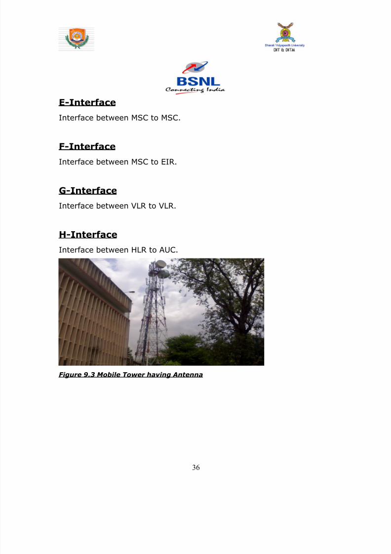
8142019 Dipti Report
httpslidepdfcomreaderfulldipti-report 3862
bull The mobile equipment or terminal
bull The Subscriber Identity Module (SIM)
Figure 95 Mobile Equipment and SIM
The Terminal
There are different types of terminals distinguished principally by their
power and application
bull The `fixed terminals are the ones installed in cars Their
maximum allowed output power is 20 W
bull The GSM portable terminals can also be installed in vehicles
Their maximum allowed output power is 8W
bull The handhels terminals have experienced the biggest success
thanks to thei weight and volume which are continuously
decreasing These terminals can emit up to 2 W The evolution of
technologies allows to decrease the maximum allowed power to
08 W
38
8142019 Dipti Report
httpslidepdfcomreaderfulldipti-report 3962
The SIM
The SIM is a smart card that identifies the terminal By inserting the
SIM card into the terminal the user can have access to all the
subscribed services Without the SIM card the terminal is not
operational
Another advantage of the SIM card is the mobility of the users In fact
the only element that personalizes a terminal is the SIM card
922 The Base Station Subsystem
The BSS connects the Mobile Station and the NSS It is in charge of
the transmission and reception The BSS can be divided into two parts
bull The Base Transceiver Station (BTS) or Base Station
bull The Base Station Controller (BSC)
9221 The Base Transceiver Station
The BTS corresponds to the transceivers and antennas used in
each cell of the network A BTS is usually placed in the center of a cell
Its transmitting power defines the size of a cell Each BTS has between
one and sixteen transceivers depending on the density of users in the
cell
39
8142019 Dipti Report
httpslidepdfcomreaderfulldipti-report 4062
40
8142019 Dipti Report
httpslidepdfcomreaderfulldipti-report 4162
Figure96 Picture of BTS
9222 The Base Station Controller
The BSC controls a group of BTS and manages their radio ressources
A BSC is principally in charge of handovers frequency hopping
exchange functions and control of the radio frequency power levels of
the BTSs
41
8142019 Dipti Report
httpslidepdfcomreaderfulldipti-report 4262
Figure 97 Picture of BSC
42
8142019 Dipti Report
httpslidepdfcomreaderfulldipti-report 4362
923 The Network and Switching Subsystem
Its main role is to manage the communications between the mobile
users and other users such as mobile users ISDN users fixed
telephony users etc It also includes data bases needed in order to
store information about the subscribers and to manage their mobility
The different components of the NSS are described below
92 31 The Mobile services Switching Center (MSC)
It is the central component of the NSS The MSC
performs the switching functions of the network It also provides
connection to other networks
9232 The Gateway Mobile services Switching Center
(GMSC)
A gateway is a node interconnecting two networks The GMSC is the
interface between the mobile cellular network and the PSTN It is in
charge of routing calls from the fixed network towards a GSM user
The GMSC is often implemented in the same machines as the MSC
92 33 Home location register (HLR)
HLR stores information of subscriber belonging to the covering area of
MSC It also stores the current location of these subscribers and the
service to which they have access
43
8142019 Dipti Report
httpslidepdfcomreaderfulldipti-report 4462
9234 Visitor location register (VLR)
VLR contains information from subscriberrsquos HLR necessary in order to
provide the subscribed services to visiting users
VLR is always implemented together with a MSC soothe area under
control of the MSC is also the area under control of the VLR
9235 Authentication center (AUC)
AUC register is used for security purpose It helps to verify the userrsquos
identity
9236 Equipment identity register (EIR )
EIR contains a list of all valid terminals The EIR allows the forbid calls
from stolen or unauthorized terminals
92 37 The GSM Interworking Unit (GIWU)
The GIWU corresponds to an interface to various networks for data
communications During these communications the transmission of
speech and data can be alternated
924 The Operation and Support Subsystem (OSS)
The OSS is connected to the different components of the NSS and to
the BSC in order to control and monitor the GSM system It is also in
charge of controlling the traffic load of the BSS
44
8142019 Dipti Report
httpslidepdfcomreaderfulldipti-report 4562
Figure 98 BLOCK DIAGRAM OF MOBILE TOWER AND
TRANSMISSION
93 The GSM functions
In this paragraph the description of the GSM network is focused on
the differents functions to fulfil by the network and not on its physical
components In GSM five main functions can be defined
bull Transmission
bull Radio Resources management (RR)
bull Mobility Management (MM)
bull Communication Management (CM)
bull Operation Administration and Maintenance (OAM)
45
8142019 Dipti Report
httpslidepdfcomreaderfulldipti-report 4662
94 GSM Frequencies
In principle the GSM system can be implemented in any frequency
band However there are several bands where GSM terminals are or
will shortly be available Furthermore GSM terminals may incorporate
one or more of the GSM frequency bands listed below to facilitate
roaming on a global basis
Frequency Range
GSM400 4504 - 4576 MHz paired with 4604 - 4676
MHz
or
4788 - 486 MHz paired with 4888 - 496 MHz
GSM 850 824 - 849 MHz paired with 869 - 894 MHz
GSM900 880 - 915 MHz paired with 925 - 960 MHz
GSM1800 1710 - 1785 MHz paired with 1805 - 1880 MHz
GSM1900 1850 - 1910 MHz paired with 1930 - 1990 MHz
95 Frequency allocation
Two frequency bands of 25 Mhz each one have been allocated for the
GSM system
bull The band 890-915 Mhz has been allocated for the uplink
direction (transmitting from the mobile station to the base
station)
46
8142019 Dipti Report
httpslidepdfcomreaderfulldipti-report 4762
bull The band 935-960 Mhz has been allocated for the downlink
direction (transmitting from the base station to the mobile
station)
But not all the countries can use the whole GSM frequency bands
This is due principally to military reasons and to the existence of
previous analog systems using part of the two 25 Mhz frequency
bands
Traffic is measured in ERLANG
BSC Capacity is 1min 5000 ERLANG
Now in 3G in respect of BSC MSC
RNC(Radio Network Control) is used
CHAPTER 10
47
8142019 Dipti Report
httpslidepdfcomreaderfulldipti-report 4862
INTRODUCTION
MAIN DISTRIBUTION FRAME (MDF)
The main distribution frame acts as a link between the
exchange indoor and the exchange outdoor It not only
connects the exchange with the subscriber but also protects
the exchange from environmental hazards such as lightning
strike
There are two sides in a MDF -
101 Line side - The line side belongs to the outdoor The
subscriber is connected to the exchange via the MDF In the
line side there are analog connections
This side of the exchange consists of verticals Each vertical
has 100 trans and receive pairs connected to it ie 100
subscribers are connected to the exchange via one vertical
Each vertical corresponds to a particular pillar The line wires
emanating from the verticals are connected to a cabinet
from where it is taken to a pillar which then is connected to
48
8142019 Dipti Report
httpslidepdfcomreaderfulldipti-report 4962
a distribution pole (DP) From here the lines are distributed
to the subscribers
For line testing on the line side the dial tone is tested on the
vertical first If it is found to be ok then the testing is carried
forward to the cabinet From here line wires are carried
forward in a cluster of around 100 pairs to the pillar A pillar
is usually located in the central part of an area where the
pillar is established so that distribution is convenient and
less expensive One distribution pole is set up to provide
connection to around 15 to 20 homes From here the
subscribers are directly connected
102 Exchange side - Exchange side belongs to the
exchange On the exchange side of the MDF the connections
are DigitalThe connection between the
exchange and the subscriber is made in various stages On
the exchange side the MDF is directly connected to the DLU
in the SN (Switching Network) In the MDF the two sides
49
8142019 Dipti Report
httpslidepdfcomreaderfulldipti-report 5062
are connected through a jumper wire The line testing for
the exchange is done first here using a dial tone checker
For rectifying errors each subscriber is assigned an
Equipment Number (NE) This number is the identification
mark of the subscriber for the exchange It represents the
location in the DLU from where the connection is provided
The DLU is then connected to the LTG (Line Trunk Groups)
from here the switching network is connected
CHAPTER 11
50
8142019 Dipti Report
httpslidepdfcomreaderfulldipti-report 5162
INTRODUCTION
THE POWER PLANT
Power Plant is the main part of an Exchange It provide uninterrupted
power to the exchange continuously it also plays the role of converting
AC power to DC power
The arrangement made has one active and two standby systems for
supplying power This makes the system extremely reliable even in the
areas with acute power shortage Options like maintenance free
batteries (VRLA) also make it cost effective
There are three supply options in the power plant
bull The AC mains
bull The Value Regulated Lead Acid battery set
bull The engine alternator
111 The AC Mains
The exchange requires a constant supply voltage of 48V (DC) in the
running condition So the voltage obtained from which is 66 KV needs
51
8142019 Dipti Report
httpslidepdfcomreaderfulldipti-report 5262
to be stepped down and rectified to DC voltage This function is
performed by the float rectifier unit
112 The Battery Set
There are two sets of VRLA batteries which are maintenance free
batteries Each set is capable of providing the required 48V DC supply
and have a capacity of 4000 AH (Ampere Hour) They are named as
set A and set B One set is active while the other set is available for
standby In case AC mains power is on both the sets of batteries get
charged As soon as there is a power cut the load gets switched over
to the battery set and one of the sets gets active while the other is
available for standby But even this source cannot be trusted for very
long durations as each set is capable of sustaining the load only for
about 3 hours So we need another alternative to provide a fool proof
system This calls for the use of the engine alternator
1113 The Engine Alternator
Usually the battery set is always kept for standby operation In case
there is a power cut the battery set operates hardly for 5 to 10
minutes which is the time taken for the alternator to start
There are also two sets of generators which are rated as follows
bull 66 KV415V voltage rating with moisture absorber
bull 200 KVA power rating
52
8142019 Dipti Report
httpslidepdfcomreaderfulldipti-report 5362
CHAPTER 12
INTRODUCTION
OPERATION AND MAINTENANCE TERMINAL
On the basis of Operation and maintenance terminal Function it has
been grouped into following categories
121 OPERATING FUNCTIONS
1 Charging function
2 Continuous connectivity management
3 Memory management of Translator
122 SUPERVISION FUNCTIONS
1 Circuit tests
2 Line and subscriber set tests
3 Load and traffic observation
123 MAINTENANCE FUNCTIONS
1 Maintenance of exchange control unit memories
2 Fault location and trouble-shooting aid function
3 Telephone equipment position
53
8142019 Dipti Report
httpslidepdfcomreaderfulldipti-report 5462
CHAPTER 13
INTRODUCTION
PULSE CODE MODULATION
PCM is a process which converts a continuous analog signal into digital
signals It is a Multichannel transmission technique that explores the
advantage of digital transmission over analog transmission It only
realizes the advantages of improved transmission limits greater noise
immunity lesser distortion of dial pulses but also economy
Converting continuous analog signal into digital signals is
carried out in three stages-
131 Sampling- Sampling is a periodical
measurement of the value of the analog signal A sampled
data contains all the information of the signal if the
sampling frequency is at least twice the highest frequency
of the signal to be sampled As the signals in telephony are
band limited to 300-3400Hz a sampling are frequency of
8000Hz ie every 125 micro seconds is sufficient
54
8142019 Dipti Report
httpslidepdfcomreaderfulldipti-report 5562
132 Quantizing - representation of their amplitude is forced to
take certain value To ensure that the ratio between signal amplitude
and errors introduced by quantized and encoded (companding) law is
applied
133 Encoding - PAM signals are quantized and encoded into 8
bit symmetrical binary code and transmitted on line during the time
slot allotted to that channel as PCM signals
At the receive side these PCM signals are decoded into PAM
signals and smoothed out by passing through low-pass filters to filters
to get back originals signals
This PCM system can support 30 simultaneous telephone conversation
and optionally 8 telegraphteleprinter channels on one line Individual
channels have a transmission speed of 64 Kbitss and the total
transmission rate for all 32 channels in the system is 2048 Kbitss
55
8142019 Dipti Report
httpslidepdfcomreaderfulldipti-report 5662
CHAPTER 14
INTRODUCTION
SWITCHING
There are two types of switching namely CIRCUIT Switching and
PACKET Switching
141 CIRCUIT SWITCHING - A circuit switching network is onethat establishes a dedicated circuit between nodes and terminals
before the users may communicate Each circuit that is dedicated
cannot be used by other callers until the circuit is released and a new
connection is set up Even if no actual communication is taking place in
a dedicated circuit then that channel still remains unavailable to other
users Channels that are available for new calls to be set up are said to
be idle Early telephone exchanges are a suitable example of circuitswitching
142 PACKET SWITCHING - Packet switching is a
communications paradigm in which packets are routed between nodes
over data links shared with other traffic This contrasts with the other
56
8142019 Dipti Report
httpslidepdfcomreaderfulldipti-report 5762
principal paradigm circuit switching which sets up a dedicated
connection between the two nodes for their exclusive use for the
duration of the communication Packet switching is used to optimize
the use of the channel capacity available in a network to minimize the
transmission latency (ie the time it takes for data to pass across the
network) and to increase robustness of communication
143 Circuit Switching vs Packet
Switching
In principle circuit switching and packet switching both are used in
high-capacity networks In circuit-switched networks network
resources are static set in ldquocopperrdquo if you will from the sender to
receiver before the start of the transfer thus creating a ldquocircuitrdquo The
resources remain dedicated to the circuit during the entire transfer and
the entire message follows the same path In packet-switched
networks the message is broken into packets each of which can take
a different route to the destination where the packets are recompiled
into the original message Circuit switching contrasts with packet
switching which splits traffic data (for instance digital representation
of sound or computer data) into chunks called packets that are
routed over a shared network Packet switching networks do not
require a circuit to be established and allow many pairs of nodes to
communicate almost simultaneously over the same channel Each
57
8142019 Dipti Report
httpslidepdfcomreaderfulldipti-report 5862
packet is individually addressed precluding the need for a dedicated
path to help the packet find its way to its destination
CHAPTER 15
CONCLUSION
This Practical Training has given me an opportunity to know about various
technologies working behind in todayrsquos advanced world of telecommunication
All those that we read in our Book only theoretically by this training I observe all
those practically I come across different units in telecom exchange like
E10BOCBEWSD Mobile (GSM) BSC and BTS MDF and Power Plant
and Broadband I not only watch those equipment but also know about those
there working there functions and also how by work to provide us facility of
telecomI am very grateful to those persons who helped directly amp
indirectly in the successful completion of this practical training and this will
surely be fruitful in future
58
8142019 Dipti Report
httpslidepdfcomreaderfulldipti-report 5962
CHAPTER 16
APPENDIX
161 Loading statement of Jamshedpur OCB-283Capacity of the TAXndash22K Loading ndash 5915
Station IC OG Between Total PCM
Arra Nil Nil 30 1
Ambala Nil Nil 30 1
Bangalore Nil Nil 61 2
Bhagalpur Nil Nil 60 2
Chennai Nil Nil 30 1
Cuttack Nil Nil 184 6
Daltengung Nil Nil 30 1
Darbhanga Nil Nil 60 2
Delhi bsnl Nil Nil 122 4Delhi mtnl Nil Nil 91 3
Dhanbad Nil Nil 122 4
Dumka Nil Nil 30 1
Ericson1 Nil Nil 494 16
Ericson2 Ni Nil 122 4
Gaya Nil Nil 61 2
Hajipur Nil Nil 30 1
Hazaribag Nil Nil 91 3
Hyderabad Nil Nil 123 4
Kolkata Nil Nil 246 8
Kharagpur Nil Nil 91 3
Katihar Nil Nil 30 1
Lucknow Nil Nil 90 3
Mumbai bsnl Nil Nil 61 2
Mumbai mtnl Nil Nil 62 2
59
8142019 Dipti Report
httpslidepdfcomreaderfulldipti-report 6062
Munger Nil Nil 30 1
Muzafferpur Nil Nil 61 2
Nortel Nil Nil 587 19
Purulia Nil Nil 61 2
Patna Nil Nil 151 5
Patliputr Nil Nil 122 8
Raurkela Nil Nil 91 3
Ranchi 15 45 680 24
Sasaram Nil Nil 30 1
Saharsa Nil Nil 30 1Sakla Nil Nil 153 5
Sambalpur Nil Nil 30 1
Tarang Nil Nil 154 5
Baripada Nil Nil 60 2
MSCA Nil Nil 309 10
Msc bokaro Nil Nil 618 20
Total 15 45 5518 182
162 OCB ndash 283 MAIN TELEPHONE EXCHANGES
EXCHANGE CAPACITY PCM
Main Exchange 12k -
Rsu Telco 11256 15
Rsu Adityapur 3k -
Rsu Sidhgora 4k 12
Rsu Mani fit 4256k 11
Rsu Govindpur 2k 10
Rsu Tatanagar 4256k 14
Rsu Parsudih 4k 11
Dlcjsr 6rt -Dlc Parsudih 2rt -
DlcTelco 1rt -
RsuKharkai 1k -
Ghatsila 6585 12
Bahragora 6594 3
Chaibasa 6582 12
60
8142019 Dipti Report
httpslidepdfcomreaderfulldipti-report 6162
Chakardharpur 6587 5
Manoharpur 6593 2
Saraikela 6597 7
Chandil 6591 -
Jhinkpani 6589 -
Jagannathpur 6588 -
Giriburu 6596 4
Nowamundi 6596 5
Kharzwara 6583 -
163 PHONE CODES AND THEIR EXCHANGE CODE
61
PHONE CODE EXCHANGE
2758 JSR
2756 JSR
2421 JSR
243 JSR
244 JSR
248 JSR
222 JSR223 JSR
265 SNK
240 ADR
220 ADR
2370-3 ADR
2380-3 ADR
2386-87 GMR
246 amp 236 MNG
29 7 DIGIT WJSR
2270 GVP2277 GVP
2290-95 TAT
2296 PSD
230-231 KDM
234 GOL
226228 TLC
221 SDG
232 LIC
2249 KHL
8142019 Dipti Report
httpslidepdfcomreaderfulldipti-report 6262
8142019 Dipti Report
httpslidepdfcomreaderfulldipti-report 3962
The SIM
The SIM is a smart card that identifies the terminal By inserting the
SIM card into the terminal the user can have access to all the
subscribed services Without the SIM card the terminal is not
operational
Another advantage of the SIM card is the mobility of the users In fact
the only element that personalizes a terminal is the SIM card
922 The Base Station Subsystem
The BSS connects the Mobile Station and the NSS It is in charge of
the transmission and reception The BSS can be divided into two parts
bull The Base Transceiver Station (BTS) or Base Station
bull The Base Station Controller (BSC)
9221 The Base Transceiver Station
The BTS corresponds to the transceivers and antennas used in
each cell of the network A BTS is usually placed in the center of a cell
Its transmitting power defines the size of a cell Each BTS has between
one and sixteen transceivers depending on the density of users in the
cell
39
8142019 Dipti Report
httpslidepdfcomreaderfulldipti-report 4062
40
8142019 Dipti Report
httpslidepdfcomreaderfulldipti-report 4162
Figure96 Picture of BTS
9222 The Base Station Controller
The BSC controls a group of BTS and manages their radio ressources
A BSC is principally in charge of handovers frequency hopping
exchange functions and control of the radio frequency power levels of
the BTSs
41
8142019 Dipti Report
httpslidepdfcomreaderfulldipti-report 4262
Figure 97 Picture of BSC
42
8142019 Dipti Report
httpslidepdfcomreaderfulldipti-report 4362
923 The Network and Switching Subsystem
Its main role is to manage the communications between the mobile
users and other users such as mobile users ISDN users fixed
telephony users etc It also includes data bases needed in order to
store information about the subscribers and to manage their mobility
The different components of the NSS are described below
92 31 The Mobile services Switching Center (MSC)
It is the central component of the NSS The MSC
performs the switching functions of the network It also provides
connection to other networks
9232 The Gateway Mobile services Switching Center
(GMSC)
A gateway is a node interconnecting two networks The GMSC is the
interface between the mobile cellular network and the PSTN It is in
charge of routing calls from the fixed network towards a GSM user
The GMSC is often implemented in the same machines as the MSC
92 33 Home location register (HLR)
HLR stores information of subscriber belonging to the covering area of
MSC It also stores the current location of these subscribers and the
service to which they have access
43
8142019 Dipti Report
httpslidepdfcomreaderfulldipti-report 4462
9234 Visitor location register (VLR)
VLR contains information from subscriberrsquos HLR necessary in order to
provide the subscribed services to visiting users
VLR is always implemented together with a MSC soothe area under
control of the MSC is also the area under control of the VLR
9235 Authentication center (AUC)
AUC register is used for security purpose It helps to verify the userrsquos
identity
9236 Equipment identity register (EIR )
EIR contains a list of all valid terminals The EIR allows the forbid calls
from stolen or unauthorized terminals
92 37 The GSM Interworking Unit (GIWU)
The GIWU corresponds to an interface to various networks for data
communications During these communications the transmission of
speech and data can be alternated
924 The Operation and Support Subsystem (OSS)
The OSS is connected to the different components of the NSS and to
the BSC in order to control and monitor the GSM system It is also in
charge of controlling the traffic load of the BSS
44
8142019 Dipti Report
httpslidepdfcomreaderfulldipti-report 4562
Figure 98 BLOCK DIAGRAM OF MOBILE TOWER AND
TRANSMISSION
93 The GSM functions
In this paragraph the description of the GSM network is focused on
the differents functions to fulfil by the network and not on its physical
components In GSM five main functions can be defined
bull Transmission
bull Radio Resources management (RR)
bull Mobility Management (MM)
bull Communication Management (CM)
bull Operation Administration and Maintenance (OAM)
45
8142019 Dipti Report
httpslidepdfcomreaderfulldipti-report 4662
94 GSM Frequencies
In principle the GSM system can be implemented in any frequency
band However there are several bands where GSM terminals are or
will shortly be available Furthermore GSM terminals may incorporate
one or more of the GSM frequency bands listed below to facilitate
roaming on a global basis
Frequency Range
GSM400 4504 - 4576 MHz paired with 4604 - 4676
MHz
or
4788 - 486 MHz paired with 4888 - 496 MHz
GSM 850 824 - 849 MHz paired with 869 - 894 MHz
GSM900 880 - 915 MHz paired with 925 - 960 MHz
GSM1800 1710 - 1785 MHz paired with 1805 - 1880 MHz
GSM1900 1850 - 1910 MHz paired with 1930 - 1990 MHz
95 Frequency allocation
Two frequency bands of 25 Mhz each one have been allocated for the
GSM system
bull The band 890-915 Mhz has been allocated for the uplink
direction (transmitting from the mobile station to the base
station)
46
8142019 Dipti Report
httpslidepdfcomreaderfulldipti-report 4762
bull The band 935-960 Mhz has been allocated for the downlink
direction (transmitting from the base station to the mobile
station)
But not all the countries can use the whole GSM frequency bands
This is due principally to military reasons and to the existence of
previous analog systems using part of the two 25 Mhz frequency
bands
Traffic is measured in ERLANG
BSC Capacity is 1min 5000 ERLANG
Now in 3G in respect of BSC MSC
RNC(Radio Network Control) is used
CHAPTER 10
47
8142019 Dipti Report
httpslidepdfcomreaderfulldipti-report 4862
INTRODUCTION
MAIN DISTRIBUTION FRAME (MDF)
The main distribution frame acts as a link between the
exchange indoor and the exchange outdoor It not only
connects the exchange with the subscriber but also protects
the exchange from environmental hazards such as lightning
strike
There are two sides in a MDF -
101 Line side - The line side belongs to the outdoor The
subscriber is connected to the exchange via the MDF In the
line side there are analog connections
This side of the exchange consists of verticals Each vertical
has 100 trans and receive pairs connected to it ie 100
subscribers are connected to the exchange via one vertical
Each vertical corresponds to a particular pillar The line wires
emanating from the verticals are connected to a cabinet
from where it is taken to a pillar which then is connected to
48
8142019 Dipti Report
httpslidepdfcomreaderfulldipti-report 4962
a distribution pole (DP) From here the lines are distributed
to the subscribers
For line testing on the line side the dial tone is tested on the
vertical first If it is found to be ok then the testing is carried
forward to the cabinet From here line wires are carried
forward in a cluster of around 100 pairs to the pillar A pillar
is usually located in the central part of an area where the
pillar is established so that distribution is convenient and
less expensive One distribution pole is set up to provide
connection to around 15 to 20 homes From here the
subscribers are directly connected
102 Exchange side - Exchange side belongs to the
exchange On the exchange side of the MDF the connections
are DigitalThe connection between the
exchange and the subscriber is made in various stages On
the exchange side the MDF is directly connected to the DLU
in the SN (Switching Network) In the MDF the two sides
49
8142019 Dipti Report
httpslidepdfcomreaderfulldipti-report 5062
are connected through a jumper wire The line testing for
the exchange is done first here using a dial tone checker
For rectifying errors each subscriber is assigned an
Equipment Number (NE) This number is the identification
mark of the subscriber for the exchange It represents the
location in the DLU from where the connection is provided
The DLU is then connected to the LTG (Line Trunk Groups)
from here the switching network is connected
CHAPTER 11
50
8142019 Dipti Report
httpslidepdfcomreaderfulldipti-report 5162
INTRODUCTION
THE POWER PLANT
Power Plant is the main part of an Exchange It provide uninterrupted
power to the exchange continuously it also plays the role of converting
AC power to DC power
The arrangement made has one active and two standby systems for
supplying power This makes the system extremely reliable even in the
areas with acute power shortage Options like maintenance free
batteries (VRLA) also make it cost effective
There are three supply options in the power plant
bull The AC mains
bull The Value Regulated Lead Acid battery set
bull The engine alternator
111 The AC Mains
The exchange requires a constant supply voltage of 48V (DC) in the
running condition So the voltage obtained from which is 66 KV needs
51
8142019 Dipti Report
httpslidepdfcomreaderfulldipti-report 5262
to be stepped down and rectified to DC voltage This function is
performed by the float rectifier unit
112 The Battery Set
There are two sets of VRLA batteries which are maintenance free
batteries Each set is capable of providing the required 48V DC supply
and have a capacity of 4000 AH (Ampere Hour) They are named as
set A and set B One set is active while the other set is available for
standby In case AC mains power is on both the sets of batteries get
charged As soon as there is a power cut the load gets switched over
to the battery set and one of the sets gets active while the other is
available for standby But even this source cannot be trusted for very
long durations as each set is capable of sustaining the load only for
about 3 hours So we need another alternative to provide a fool proof
system This calls for the use of the engine alternator
1113 The Engine Alternator
Usually the battery set is always kept for standby operation In case
there is a power cut the battery set operates hardly for 5 to 10
minutes which is the time taken for the alternator to start
There are also two sets of generators which are rated as follows
bull 66 KV415V voltage rating with moisture absorber
bull 200 KVA power rating
52
8142019 Dipti Report
httpslidepdfcomreaderfulldipti-report 5362
CHAPTER 12
INTRODUCTION
OPERATION AND MAINTENANCE TERMINAL
On the basis of Operation and maintenance terminal Function it has
been grouped into following categories
121 OPERATING FUNCTIONS
1 Charging function
2 Continuous connectivity management
3 Memory management of Translator
122 SUPERVISION FUNCTIONS
1 Circuit tests
2 Line and subscriber set tests
3 Load and traffic observation
123 MAINTENANCE FUNCTIONS
1 Maintenance of exchange control unit memories
2 Fault location and trouble-shooting aid function
3 Telephone equipment position
53
8142019 Dipti Report
httpslidepdfcomreaderfulldipti-report 5462
CHAPTER 13
INTRODUCTION
PULSE CODE MODULATION
PCM is a process which converts a continuous analog signal into digital
signals It is a Multichannel transmission technique that explores the
advantage of digital transmission over analog transmission It only
realizes the advantages of improved transmission limits greater noise
immunity lesser distortion of dial pulses but also economy
Converting continuous analog signal into digital signals is
carried out in three stages-
131 Sampling- Sampling is a periodical
measurement of the value of the analog signal A sampled
data contains all the information of the signal if the
sampling frequency is at least twice the highest frequency
of the signal to be sampled As the signals in telephony are
band limited to 300-3400Hz a sampling are frequency of
8000Hz ie every 125 micro seconds is sufficient
54
8142019 Dipti Report
httpslidepdfcomreaderfulldipti-report 5562
132 Quantizing - representation of their amplitude is forced to
take certain value To ensure that the ratio between signal amplitude
and errors introduced by quantized and encoded (companding) law is
applied
133 Encoding - PAM signals are quantized and encoded into 8
bit symmetrical binary code and transmitted on line during the time
slot allotted to that channel as PCM signals
At the receive side these PCM signals are decoded into PAM
signals and smoothed out by passing through low-pass filters to filters
to get back originals signals
This PCM system can support 30 simultaneous telephone conversation
and optionally 8 telegraphteleprinter channels on one line Individual
channels have a transmission speed of 64 Kbitss and the total
transmission rate for all 32 channels in the system is 2048 Kbitss
55
8142019 Dipti Report
httpslidepdfcomreaderfulldipti-report 5662
CHAPTER 14
INTRODUCTION
SWITCHING
There are two types of switching namely CIRCUIT Switching and
PACKET Switching
141 CIRCUIT SWITCHING - A circuit switching network is onethat establishes a dedicated circuit between nodes and terminals
before the users may communicate Each circuit that is dedicated
cannot be used by other callers until the circuit is released and a new
connection is set up Even if no actual communication is taking place in
a dedicated circuit then that channel still remains unavailable to other
users Channels that are available for new calls to be set up are said to
be idle Early telephone exchanges are a suitable example of circuitswitching
142 PACKET SWITCHING - Packet switching is a
communications paradigm in which packets are routed between nodes
over data links shared with other traffic This contrasts with the other
56
8142019 Dipti Report
httpslidepdfcomreaderfulldipti-report 5762
principal paradigm circuit switching which sets up a dedicated
connection between the two nodes for their exclusive use for the
duration of the communication Packet switching is used to optimize
the use of the channel capacity available in a network to minimize the
transmission latency (ie the time it takes for data to pass across the
network) and to increase robustness of communication
143 Circuit Switching vs Packet
Switching
In principle circuit switching and packet switching both are used in
high-capacity networks In circuit-switched networks network
resources are static set in ldquocopperrdquo if you will from the sender to
receiver before the start of the transfer thus creating a ldquocircuitrdquo The
resources remain dedicated to the circuit during the entire transfer and
the entire message follows the same path In packet-switched
networks the message is broken into packets each of which can take
a different route to the destination where the packets are recompiled
into the original message Circuit switching contrasts with packet
switching which splits traffic data (for instance digital representation
of sound or computer data) into chunks called packets that are
routed over a shared network Packet switching networks do not
require a circuit to be established and allow many pairs of nodes to
communicate almost simultaneously over the same channel Each
57
8142019 Dipti Report
httpslidepdfcomreaderfulldipti-report 5862
packet is individually addressed precluding the need for a dedicated
path to help the packet find its way to its destination
CHAPTER 15
CONCLUSION
This Practical Training has given me an opportunity to know about various
technologies working behind in todayrsquos advanced world of telecommunication
All those that we read in our Book only theoretically by this training I observe all
those practically I come across different units in telecom exchange like
E10BOCBEWSD Mobile (GSM) BSC and BTS MDF and Power Plant
and Broadband I not only watch those equipment but also know about those
there working there functions and also how by work to provide us facility of
telecomI am very grateful to those persons who helped directly amp
indirectly in the successful completion of this practical training and this will
surely be fruitful in future
58
8142019 Dipti Report
httpslidepdfcomreaderfulldipti-report 5962
CHAPTER 16
APPENDIX
161 Loading statement of Jamshedpur OCB-283Capacity of the TAXndash22K Loading ndash 5915
Station IC OG Between Total PCM
Arra Nil Nil 30 1
Ambala Nil Nil 30 1
Bangalore Nil Nil 61 2
Bhagalpur Nil Nil 60 2
Chennai Nil Nil 30 1
Cuttack Nil Nil 184 6
Daltengung Nil Nil 30 1
Darbhanga Nil Nil 60 2
Delhi bsnl Nil Nil 122 4Delhi mtnl Nil Nil 91 3
Dhanbad Nil Nil 122 4
Dumka Nil Nil 30 1
Ericson1 Nil Nil 494 16
Ericson2 Ni Nil 122 4
Gaya Nil Nil 61 2
Hajipur Nil Nil 30 1
Hazaribag Nil Nil 91 3
Hyderabad Nil Nil 123 4
Kolkata Nil Nil 246 8
Kharagpur Nil Nil 91 3
Katihar Nil Nil 30 1
Lucknow Nil Nil 90 3
Mumbai bsnl Nil Nil 61 2
Mumbai mtnl Nil Nil 62 2
59
8142019 Dipti Report
httpslidepdfcomreaderfulldipti-report 6062
Munger Nil Nil 30 1
Muzafferpur Nil Nil 61 2
Nortel Nil Nil 587 19
Purulia Nil Nil 61 2
Patna Nil Nil 151 5
Patliputr Nil Nil 122 8
Raurkela Nil Nil 91 3
Ranchi 15 45 680 24
Sasaram Nil Nil 30 1
Saharsa Nil Nil 30 1Sakla Nil Nil 153 5
Sambalpur Nil Nil 30 1
Tarang Nil Nil 154 5
Baripada Nil Nil 60 2
MSCA Nil Nil 309 10
Msc bokaro Nil Nil 618 20
Total 15 45 5518 182
162 OCB ndash 283 MAIN TELEPHONE EXCHANGES
EXCHANGE CAPACITY PCM
Main Exchange 12k -
Rsu Telco 11256 15
Rsu Adityapur 3k -
Rsu Sidhgora 4k 12
Rsu Mani fit 4256k 11
Rsu Govindpur 2k 10
Rsu Tatanagar 4256k 14
Rsu Parsudih 4k 11
Dlcjsr 6rt -Dlc Parsudih 2rt -
DlcTelco 1rt -
RsuKharkai 1k -
Ghatsila 6585 12
Bahragora 6594 3
Chaibasa 6582 12
60
8142019 Dipti Report
httpslidepdfcomreaderfulldipti-report 6162
Chakardharpur 6587 5
Manoharpur 6593 2
Saraikela 6597 7
Chandil 6591 -
Jhinkpani 6589 -
Jagannathpur 6588 -
Giriburu 6596 4
Nowamundi 6596 5
Kharzwara 6583 -
163 PHONE CODES AND THEIR EXCHANGE CODE
61
PHONE CODE EXCHANGE
2758 JSR
2756 JSR
2421 JSR
243 JSR
244 JSR
248 JSR
222 JSR223 JSR
265 SNK
240 ADR
220 ADR
2370-3 ADR
2380-3 ADR
2386-87 GMR
246 amp 236 MNG
29 7 DIGIT WJSR
2270 GVP2277 GVP
2290-95 TAT
2296 PSD
230-231 KDM
234 GOL
226228 TLC
221 SDG
232 LIC
2249 KHL
8142019 Dipti Report
httpslidepdfcomreaderfulldipti-report 6262
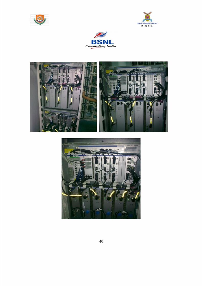
8142019 Dipti Report
httpslidepdfcomreaderfulldipti-report 4062
40
8142019 Dipti Report
httpslidepdfcomreaderfulldipti-report 4162
Figure96 Picture of BTS
9222 The Base Station Controller
The BSC controls a group of BTS and manages their radio ressources
A BSC is principally in charge of handovers frequency hopping
exchange functions and control of the radio frequency power levels of
the BTSs
41
8142019 Dipti Report
httpslidepdfcomreaderfulldipti-report 4262
Figure 97 Picture of BSC
42
8142019 Dipti Report
httpslidepdfcomreaderfulldipti-report 4362
923 The Network and Switching Subsystem
Its main role is to manage the communications between the mobile
users and other users such as mobile users ISDN users fixed
telephony users etc It also includes data bases needed in order to
store information about the subscribers and to manage their mobility
The different components of the NSS are described below
92 31 The Mobile services Switching Center (MSC)
It is the central component of the NSS The MSC
performs the switching functions of the network It also provides
connection to other networks
9232 The Gateway Mobile services Switching Center
(GMSC)
A gateway is a node interconnecting two networks The GMSC is the
interface between the mobile cellular network and the PSTN It is in
charge of routing calls from the fixed network towards a GSM user
The GMSC is often implemented in the same machines as the MSC
92 33 Home location register (HLR)
HLR stores information of subscriber belonging to the covering area of
MSC It also stores the current location of these subscribers and the
service to which they have access
43
8142019 Dipti Report
httpslidepdfcomreaderfulldipti-report 4462
9234 Visitor location register (VLR)
VLR contains information from subscriberrsquos HLR necessary in order to
provide the subscribed services to visiting users
VLR is always implemented together with a MSC soothe area under
control of the MSC is also the area under control of the VLR
9235 Authentication center (AUC)
AUC register is used for security purpose It helps to verify the userrsquos
identity
9236 Equipment identity register (EIR )
EIR contains a list of all valid terminals The EIR allows the forbid calls
from stolen or unauthorized terminals
92 37 The GSM Interworking Unit (GIWU)
The GIWU corresponds to an interface to various networks for data
communications During these communications the transmission of
speech and data can be alternated
924 The Operation and Support Subsystem (OSS)
The OSS is connected to the different components of the NSS and to
the BSC in order to control and monitor the GSM system It is also in
charge of controlling the traffic load of the BSS
44
8142019 Dipti Report
httpslidepdfcomreaderfulldipti-report 4562
Figure 98 BLOCK DIAGRAM OF MOBILE TOWER AND
TRANSMISSION
93 The GSM functions
In this paragraph the description of the GSM network is focused on
the differents functions to fulfil by the network and not on its physical
components In GSM five main functions can be defined
bull Transmission
bull Radio Resources management (RR)
bull Mobility Management (MM)
bull Communication Management (CM)
bull Operation Administration and Maintenance (OAM)
45
8142019 Dipti Report
httpslidepdfcomreaderfulldipti-report 4662
94 GSM Frequencies
In principle the GSM system can be implemented in any frequency
band However there are several bands where GSM terminals are or
will shortly be available Furthermore GSM terminals may incorporate
one or more of the GSM frequency bands listed below to facilitate
roaming on a global basis
Frequency Range
GSM400 4504 - 4576 MHz paired with 4604 - 4676
MHz
or
4788 - 486 MHz paired with 4888 - 496 MHz
GSM 850 824 - 849 MHz paired with 869 - 894 MHz
GSM900 880 - 915 MHz paired with 925 - 960 MHz
GSM1800 1710 - 1785 MHz paired with 1805 - 1880 MHz
GSM1900 1850 - 1910 MHz paired with 1930 - 1990 MHz
95 Frequency allocation
Two frequency bands of 25 Mhz each one have been allocated for the
GSM system
bull The band 890-915 Mhz has been allocated for the uplink
direction (transmitting from the mobile station to the base
station)
46
8142019 Dipti Report
httpslidepdfcomreaderfulldipti-report 4762
bull The band 935-960 Mhz has been allocated for the downlink
direction (transmitting from the base station to the mobile
station)
But not all the countries can use the whole GSM frequency bands
This is due principally to military reasons and to the existence of
previous analog systems using part of the two 25 Mhz frequency
bands
Traffic is measured in ERLANG
BSC Capacity is 1min 5000 ERLANG
Now in 3G in respect of BSC MSC
RNC(Radio Network Control) is used
CHAPTER 10
47
8142019 Dipti Report
httpslidepdfcomreaderfulldipti-report 4862
INTRODUCTION
MAIN DISTRIBUTION FRAME (MDF)
The main distribution frame acts as a link between the
exchange indoor and the exchange outdoor It not only
connects the exchange with the subscriber but also protects
the exchange from environmental hazards such as lightning
strike
There are two sides in a MDF -
101 Line side - The line side belongs to the outdoor The
subscriber is connected to the exchange via the MDF In the
line side there are analog connections
This side of the exchange consists of verticals Each vertical
has 100 trans and receive pairs connected to it ie 100
subscribers are connected to the exchange via one vertical
Each vertical corresponds to a particular pillar The line wires
emanating from the verticals are connected to a cabinet
from where it is taken to a pillar which then is connected to
48
8142019 Dipti Report
httpslidepdfcomreaderfulldipti-report 4962
a distribution pole (DP) From here the lines are distributed
to the subscribers
For line testing on the line side the dial tone is tested on the
vertical first If it is found to be ok then the testing is carried
forward to the cabinet From here line wires are carried
forward in a cluster of around 100 pairs to the pillar A pillar
is usually located in the central part of an area where the
pillar is established so that distribution is convenient and
less expensive One distribution pole is set up to provide
connection to around 15 to 20 homes From here the
subscribers are directly connected
102 Exchange side - Exchange side belongs to the
exchange On the exchange side of the MDF the connections
are DigitalThe connection between the
exchange and the subscriber is made in various stages On
the exchange side the MDF is directly connected to the DLU
in the SN (Switching Network) In the MDF the two sides
49
8142019 Dipti Report
httpslidepdfcomreaderfulldipti-report 5062
are connected through a jumper wire The line testing for
the exchange is done first here using a dial tone checker
For rectifying errors each subscriber is assigned an
Equipment Number (NE) This number is the identification
mark of the subscriber for the exchange It represents the
location in the DLU from where the connection is provided
The DLU is then connected to the LTG (Line Trunk Groups)
from here the switching network is connected
CHAPTER 11
50
8142019 Dipti Report
httpslidepdfcomreaderfulldipti-report 5162
INTRODUCTION
THE POWER PLANT
Power Plant is the main part of an Exchange It provide uninterrupted
power to the exchange continuously it also plays the role of converting
AC power to DC power
The arrangement made has one active and two standby systems for
supplying power This makes the system extremely reliable even in the
areas with acute power shortage Options like maintenance free
batteries (VRLA) also make it cost effective
There are three supply options in the power plant
bull The AC mains
bull The Value Regulated Lead Acid battery set
bull The engine alternator
111 The AC Mains
The exchange requires a constant supply voltage of 48V (DC) in the
running condition So the voltage obtained from which is 66 KV needs
51
8142019 Dipti Report
httpslidepdfcomreaderfulldipti-report 5262
to be stepped down and rectified to DC voltage This function is
performed by the float rectifier unit
112 The Battery Set
There are two sets of VRLA batteries which are maintenance free
batteries Each set is capable of providing the required 48V DC supply
and have a capacity of 4000 AH (Ampere Hour) They are named as
set A and set B One set is active while the other set is available for
standby In case AC mains power is on both the sets of batteries get
charged As soon as there is a power cut the load gets switched over
to the battery set and one of the sets gets active while the other is
available for standby But even this source cannot be trusted for very
long durations as each set is capable of sustaining the load only for
about 3 hours So we need another alternative to provide a fool proof
system This calls for the use of the engine alternator
1113 The Engine Alternator
Usually the battery set is always kept for standby operation In case
there is a power cut the battery set operates hardly for 5 to 10
minutes which is the time taken for the alternator to start
There are also two sets of generators which are rated as follows
bull 66 KV415V voltage rating with moisture absorber
bull 200 KVA power rating
52
8142019 Dipti Report
httpslidepdfcomreaderfulldipti-report 5362
CHAPTER 12
INTRODUCTION
OPERATION AND MAINTENANCE TERMINAL
On the basis of Operation and maintenance terminal Function it has
been grouped into following categories
121 OPERATING FUNCTIONS
1 Charging function
2 Continuous connectivity management
3 Memory management of Translator
122 SUPERVISION FUNCTIONS
1 Circuit tests
2 Line and subscriber set tests
3 Load and traffic observation
123 MAINTENANCE FUNCTIONS
1 Maintenance of exchange control unit memories
2 Fault location and trouble-shooting aid function
3 Telephone equipment position
53
8142019 Dipti Report
httpslidepdfcomreaderfulldipti-report 5462
CHAPTER 13
INTRODUCTION
PULSE CODE MODULATION
PCM is a process which converts a continuous analog signal into digital
signals It is a Multichannel transmission technique that explores the
advantage of digital transmission over analog transmission It only
realizes the advantages of improved transmission limits greater noise
immunity lesser distortion of dial pulses but also economy
Converting continuous analog signal into digital signals is
carried out in three stages-
131 Sampling- Sampling is a periodical
measurement of the value of the analog signal A sampled
data contains all the information of the signal if the
sampling frequency is at least twice the highest frequency
of the signal to be sampled As the signals in telephony are
band limited to 300-3400Hz a sampling are frequency of
8000Hz ie every 125 micro seconds is sufficient
54
8142019 Dipti Report
httpslidepdfcomreaderfulldipti-report 5562
132 Quantizing - representation of their amplitude is forced to
take certain value To ensure that the ratio between signal amplitude
and errors introduced by quantized and encoded (companding) law is
applied
133 Encoding - PAM signals are quantized and encoded into 8
bit symmetrical binary code and transmitted on line during the time
slot allotted to that channel as PCM signals
At the receive side these PCM signals are decoded into PAM
signals and smoothed out by passing through low-pass filters to filters
to get back originals signals
This PCM system can support 30 simultaneous telephone conversation
and optionally 8 telegraphteleprinter channels on one line Individual
channels have a transmission speed of 64 Kbitss and the total
transmission rate for all 32 channels in the system is 2048 Kbitss
55
8142019 Dipti Report
httpslidepdfcomreaderfulldipti-report 5662
CHAPTER 14
INTRODUCTION
SWITCHING
There are two types of switching namely CIRCUIT Switching and
PACKET Switching
141 CIRCUIT SWITCHING - A circuit switching network is onethat establishes a dedicated circuit between nodes and terminals
before the users may communicate Each circuit that is dedicated
cannot be used by other callers until the circuit is released and a new
connection is set up Even if no actual communication is taking place in
a dedicated circuit then that channel still remains unavailable to other
users Channels that are available for new calls to be set up are said to
be idle Early telephone exchanges are a suitable example of circuitswitching
142 PACKET SWITCHING - Packet switching is a
communications paradigm in which packets are routed between nodes
over data links shared with other traffic This contrasts with the other
56
8142019 Dipti Report
httpslidepdfcomreaderfulldipti-report 5762
principal paradigm circuit switching which sets up a dedicated
connection between the two nodes for their exclusive use for the
duration of the communication Packet switching is used to optimize
the use of the channel capacity available in a network to minimize the
transmission latency (ie the time it takes for data to pass across the
network) and to increase robustness of communication
143 Circuit Switching vs Packet
Switching
In principle circuit switching and packet switching both are used in
high-capacity networks In circuit-switched networks network
resources are static set in ldquocopperrdquo if you will from the sender to
receiver before the start of the transfer thus creating a ldquocircuitrdquo The
resources remain dedicated to the circuit during the entire transfer and
the entire message follows the same path In packet-switched
networks the message is broken into packets each of which can take
a different route to the destination where the packets are recompiled
into the original message Circuit switching contrasts with packet
switching which splits traffic data (for instance digital representation
of sound or computer data) into chunks called packets that are
routed over a shared network Packet switching networks do not
require a circuit to be established and allow many pairs of nodes to
communicate almost simultaneously over the same channel Each
57
8142019 Dipti Report
httpslidepdfcomreaderfulldipti-report 5862
packet is individually addressed precluding the need for a dedicated
path to help the packet find its way to its destination
CHAPTER 15
CONCLUSION
This Practical Training has given me an opportunity to know about various
technologies working behind in todayrsquos advanced world of telecommunication
All those that we read in our Book only theoretically by this training I observe all
those practically I come across different units in telecom exchange like
E10BOCBEWSD Mobile (GSM) BSC and BTS MDF and Power Plant
and Broadband I not only watch those equipment but also know about those
there working there functions and also how by work to provide us facility of
telecomI am very grateful to those persons who helped directly amp
indirectly in the successful completion of this practical training and this will
surely be fruitful in future
58
8142019 Dipti Report
httpslidepdfcomreaderfulldipti-report 5962
CHAPTER 16
APPENDIX
161 Loading statement of Jamshedpur OCB-283Capacity of the TAXndash22K Loading ndash 5915
Station IC OG Between Total PCM
Arra Nil Nil 30 1
Ambala Nil Nil 30 1
Bangalore Nil Nil 61 2
Bhagalpur Nil Nil 60 2
Chennai Nil Nil 30 1
Cuttack Nil Nil 184 6
Daltengung Nil Nil 30 1
Darbhanga Nil Nil 60 2
Delhi bsnl Nil Nil 122 4Delhi mtnl Nil Nil 91 3
Dhanbad Nil Nil 122 4
Dumka Nil Nil 30 1
Ericson1 Nil Nil 494 16
Ericson2 Ni Nil 122 4
Gaya Nil Nil 61 2
Hajipur Nil Nil 30 1
Hazaribag Nil Nil 91 3
Hyderabad Nil Nil 123 4
Kolkata Nil Nil 246 8
Kharagpur Nil Nil 91 3
Katihar Nil Nil 30 1
Lucknow Nil Nil 90 3
Mumbai bsnl Nil Nil 61 2
Mumbai mtnl Nil Nil 62 2
59
8142019 Dipti Report
httpslidepdfcomreaderfulldipti-report 6062
Munger Nil Nil 30 1
Muzafferpur Nil Nil 61 2
Nortel Nil Nil 587 19
Purulia Nil Nil 61 2
Patna Nil Nil 151 5
Patliputr Nil Nil 122 8
Raurkela Nil Nil 91 3
Ranchi 15 45 680 24
Sasaram Nil Nil 30 1
Saharsa Nil Nil 30 1Sakla Nil Nil 153 5
Sambalpur Nil Nil 30 1
Tarang Nil Nil 154 5
Baripada Nil Nil 60 2
MSCA Nil Nil 309 10
Msc bokaro Nil Nil 618 20
Total 15 45 5518 182
162 OCB ndash 283 MAIN TELEPHONE EXCHANGES
EXCHANGE CAPACITY PCM
Main Exchange 12k -
Rsu Telco 11256 15
Rsu Adityapur 3k -
Rsu Sidhgora 4k 12
Rsu Mani fit 4256k 11
Rsu Govindpur 2k 10
Rsu Tatanagar 4256k 14
Rsu Parsudih 4k 11
Dlcjsr 6rt -Dlc Parsudih 2rt -
DlcTelco 1rt -
RsuKharkai 1k -
Ghatsila 6585 12
Bahragora 6594 3
Chaibasa 6582 12
60
8142019 Dipti Report
httpslidepdfcomreaderfulldipti-report 6162
Chakardharpur 6587 5
Manoharpur 6593 2
Saraikela 6597 7
Chandil 6591 -
Jhinkpani 6589 -
Jagannathpur 6588 -
Giriburu 6596 4
Nowamundi 6596 5
Kharzwara 6583 -
163 PHONE CODES AND THEIR EXCHANGE CODE
61
PHONE CODE EXCHANGE
2758 JSR
2756 JSR
2421 JSR
243 JSR
244 JSR
248 JSR
222 JSR223 JSR
265 SNK
240 ADR
220 ADR
2370-3 ADR
2380-3 ADR
2386-87 GMR
246 amp 236 MNG
29 7 DIGIT WJSR
2270 GVP2277 GVP
2290-95 TAT
2296 PSD
230-231 KDM
234 GOL
226228 TLC
221 SDG
232 LIC
2249 KHL
8142019 Dipti Report
httpslidepdfcomreaderfulldipti-report 6262
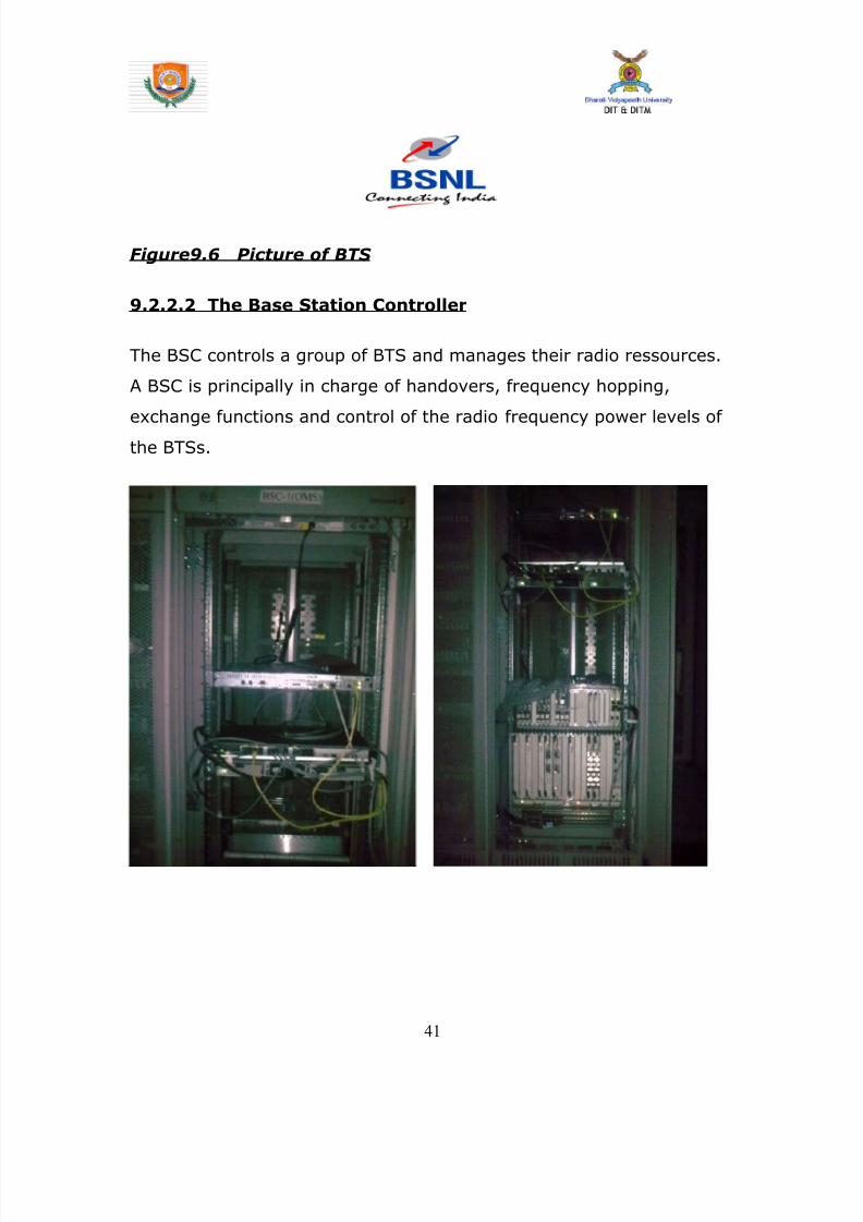
8142019 Dipti Report
httpslidepdfcomreaderfulldipti-report 4362
923 The Network and Switching Subsystem
Its main role is to manage the communications between the mobile
users and other users such as mobile users ISDN users fixed
telephony users etc It also includes data bases needed in order to
store information about the subscribers and to manage their mobility
The different components of the NSS are described below
92 31 The Mobile services Switching Center (MSC)
It is the central component of the NSS The MSC
performs the switching functions of the network It also provides
connection to other networks
9232 The Gateway Mobile services Switching Center
(GMSC)
A gateway is a node interconnecting two networks The GMSC is the
interface between the mobile cellular network and the PSTN It is in
charge of routing calls from the fixed network towards a GSM user
The GMSC is often implemented in the same machines as the MSC
92 33 Home location register (HLR)
HLR stores information of subscriber belonging to the covering area of
MSC It also stores the current location of these subscribers and the
service to which they have access
43
8142019 Dipti Report
httpslidepdfcomreaderfulldipti-report 4462
9234 Visitor location register (VLR)
VLR contains information from subscriberrsquos HLR necessary in order to
provide the subscribed services to visiting users
VLR is always implemented together with a MSC soothe area under
control of the MSC is also the area under control of the VLR
9235 Authentication center (AUC)
AUC register is used for security purpose It helps to verify the userrsquos
identity
9236 Equipment identity register (EIR )
EIR contains a list of all valid terminals The EIR allows the forbid calls
from stolen or unauthorized terminals
92 37 The GSM Interworking Unit (GIWU)
The GIWU corresponds to an interface to various networks for data
communications During these communications the transmission of
speech and data can be alternated
924 The Operation and Support Subsystem (OSS)
The OSS is connected to the different components of the NSS and to
the BSC in order to control and monitor the GSM system It is also in
charge of controlling the traffic load of the BSS
44
8142019 Dipti Report
httpslidepdfcomreaderfulldipti-report 4562
Figure 98 BLOCK DIAGRAM OF MOBILE TOWER AND
TRANSMISSION
93 The GSM functions
In this paragraph the description of the GSM network is focused on
the differents functions to fulfil by the network and not on its physical
components In GSM five main functions can be defined
bull Transmission
bull Radio Resources management (RR)
bull Mobility Management (MM)
bull Communication Management (CM)
bull Operation Administration and Maintenance (OAM)
45
8142019 Dipti Report
httpslidepdfcomreaderfulldipti-report 4662
94 GSM Frequencies
In principle the GSM system can be implemented in any frequency
band However there are several bands where GSM terminals are or
will shortly be available Furthermore GSM terminals may incorporate
one or more of the GSM frequency bands listed below to facilitate
roaming on a global basis
Frequency Range
GSM400 4504 - 4576 MHz paired with 4604 - 4676
MHz
or
4788 - 486 MHz paired with 4888 - 496 MHz
GSM 850 824 - 849 MHz paired with 869 - 894 MHz
GSM900 880 - 915 MHz paired with 925 - 960 MHz
GSM1800 1710 - 1785 MHz paired with 1805 - 1880 MHz
GSM1900 1850 - 1910 MHz paired with 1930 - 1990 MHz
95 Frequency allocation
Two frequency bands of 25 Mhz each one have been allocated for the
GSM system
bull The band 890-915 Mhz has been allocated for the uplink
direction (transmitting from the mobile station to the base
station)
46
8142019 Dipti Report
httpslidepdfcomreaderfulldipti-report 4762
bull The band 935-960 Mhz has been allocated for the downlink
direction (transmitting from the base station to the mobile
station)
But not all the countries can use the whole GSM frequency bands
This is due principally to military reasons and to the existence of
previous analog systems using part of the two 25 Mhz frequency
bands
Traffic is measured in ERLANG
BSC Capacity is 1min 5000 ERLANG
Now in 3G in respect of BSC MSC
RNC(Radio Network Control) is used
CHAPTER 10
47
8142019 Dipti Report
httpslidepdfcomreaderfulldipti-report 4862
INTRODUCTION
MAIN DISTRIBUTION FRAME (MDF)
The main distribution frame acts as a link between the
exchange indoor and the exchange outdoor It not only
connects the exchange with the subscriber but also protects
the exchange from environmental hazards such as lightning
strike
There are two sides in a MDF -
101 Line side - The line side belongs to the outdoor The
subscriber is connected to the exchange via the MDF In the
line side there are analog connections
This side of the exchange consists of verticals Each vertical
has 100 trans and receive pairs connected to it ie 100
subscribers are connected to the exchange via one vertical
Each vertical corresponds to a particular pillar The line wires
emanating from the verticals are connected to a cabinet
from where it is taken to a pillar which then is connected to
48
8142019 Dipti Report
httpslidepdfcomreaderfulldipti-report 4962
a distribution pole (DP) From here the lines are distributed
to the subscribers
For line testing on the line side the dial tone is tested on the
vertical first If it is found to be ok then the testing is carried
forward to the cabinet From here line wires are carried
forward in a cluster of around 100 pairs to the pillar A pillar
is usually located in the central part of an area where the
pillar is established so that distribution is convenient and
less expensive One distribution pole is set up to provide
connection to around 15 to 20 homes From here the
subscribers are directly connected
102 Exchange side - Exchange side belongs to the
exchange On the exchange side of the MDF the connections
are DigitalThe connection between the
exchange and the subscriber is made in various stages On
the exchange side the MDF is directly connected to the DLU
in the SN (Switching Network) In the MDF the two sides
49
8142019 Dipti Report
httpslidepdfcomreaderfulldipti-report 5062
are connected through a jumper wire The line testing for
the exchange is done first here using a dial tone checker
For rectifying errors each subscriber is assigned an
Equipment Number (NE) This number is the identification
mark of the subscriber for the exchange It represents the
location in the DLU from where the connection is provided
The DLU is then connected to the LTG (Line Trunk Groups)
from here the switching network is connected
CHAPTER 11
50
8142019 Dipti Report
httpslidepdfcomreaderfulldipti-report 5162
INTRODUCTION
THE POWER PLANT
Power Plant is the main part of an Exchange It provide uninterrupted
power to the exchange continuously it also plays the role of converting
AC power to DC power
The arrangement made has one active and two standby systems for
supplying power This makes the system extremely reliable even in the
areas with acute power shortage Options like maintenance free
batteries (VRLA) also make it cost effective
There are three supply options in the power plant
bull The AC mains
bull The Value Regulated Lead Acid battery set
bull The engine alternator
111 The AC Mains
The exchange requires a constant supply voltage of 48V (DC) in the
running condition So the voltage obtained from which is 66 KV needs
51
8142019 Dipti Report
httpslidepdfcomreaderfulldipti-report 5262
to be stepped down and rectified to DC voltage This function is
performed by the float rectifier unit
112 The Battery Set
There are two sets of VRLA batteries which are maintenance free
batteries Each set is capable of providing the required 48V DC supply
and have a capacity of 4000 AH (Ampere Hour) They are named as
set A and set B One set is active while the other set is available for
standby In case AC mains power is on both the sets of batteries get
charged As soon as there is a power cut the load gets switched over
to the battery set and one of the sets gets active while the other is
available for standby But even this source cannot be trusted for very
long durations as each set is capable of sustaining the load only for
about 3 hours So we need another alternative to provide a fool proof
system This calls for the use of the engine alternator
1113 The Engine Alternator
Usually the battery set is always kept for standby operation In case
there is a power cut the battery set operates hardly for 5 to 10
minutes which is the time taken for the alternator to start
There are also two sets of generators which are rated as follows
bull 66 KV415V voltage rating with moisture absorber
bull 200 KVA power rating
52
8142019 Dipti Report
httpslidepdfcomreaderfulldipti-report 5362
CHAPTER 12
INTRODUCTION
OPERATION AND MAINTENANCE TERMINAL
On the basis of Operation and maintenance terminal Function it has
been grouped into following categories
121 OPERATING FUNCTIONS
1 Charging function
2 Continuous connectivity management
3 Memory management of Translator
122 SUPERVISION FUNCTIONS
1 Circuit tests
2 Line and subscriber set tests
3 Load and traffic observation
123 MAINTENANCE FUNCTIONS
1 Maintenance of exchange control unit memories
2 Fault location and trouble-shooting aid function
3 Telephone equipment position
53
8142019 Dipti Report
httpslidepdfcomreaderfulldipti-report 5462
CHAPTER 13
INTRODUCTION
PULSE CODE MODULATION
PCM is a process which converts a continuous analog signal into digital
signals It is a Multichannel transmission technique that explores the
advantage of digital transmission over analog transmission It only
realizes the advantages of improved transmission limits greater noise
immunity lesser distortion of dial pulses but also economy
Converting continuous analog signal into digital signals is
carried out in three stages-
131 Sampling- Sampling is a periodical
measurement of the value of the analog signal A sampled
data contains all the information of the signal if the
sampling frequency is at least twice the highest frequency
of the signal to be sampled As the signals in telephony are
band limited to 300-3400Hz a sampling are frequency of
8000Hz ie every 125 micro seconds is sufficient
54
8142019 Dipti Report
httpslidepdfcomreaderfulldipti-report 5562
132 Quantizing - representation of their amplitude is forced to
take certain value To ensure that the ratio between signal amplitude
and errors introduced by quantized and encoded (companding) law is
applied
133 Encoding - PAM signals are quantized and encoded into 8
bit symmetrical binary code and transmitted on line during the time
slot allotted to that channel as PCM signals
At the receive side these PCM signals are decoded into PAM
signals and smoothed out by passing through low-pass filters to filters
to get back originals signals
This PCM system can support 30 simultaneous telephone conversation
and optionally 8 telegraphteleprinter channels on one line Individual
channels have a transmission speed of 64 Kbitss and the total
transmission rate for all 32 channels in the system is 2048 Kbitss
55
8142019 Dipti Report
httpslidepdfcomreaderfulldipti-report 5662
CHAPTER 14
INTRODUCTION
SWITCHING
There are two types of switching namely CIRCUIT Switching and
PACKET Switching
141 CIRCUIT SWITCHING - A circuit switching network is onethat establishes a dedicated circuit between nodes and terminals
before the users may communicate Each circuit that is dedicated
cannot be used by other callers until the circuit is released and a new
connection is set up Even if no actual communication is taking place in
a dedicated circuit then that channel still remains unavailable to other
users Channels that are available for new calls to be set up are said to
be idle Early telephone exchanges are a suitable example of circuitswitching
142 PACKET SWITCHING - Packet switching is a
communications paradigm in which packets are routed between nodes
over data links shared with other traffic This contrasts with the other
56
8142019 Dipti Report
httpslidepdfcomreaderfulldipti-report 5762
principal paradigm circuit switching which sets up a dedicated
connection between the two nodes for their exclusive use for the
duration of the communication Packet switching is used to optimize
the use of the channel capacity available in a network to minimize the
transmission latency (ie the time it takes for data to pass across the
network) and to increase robustness of communication
143 Circuit Switching vs Packet
Switching
In principle circuit switching and packet switching both are used in
high-capacity networks In circuit-switched networks network
resources are static set in ldquocopperrdquo if you will from the sender to
receiver before the start of the transfer thus creating a ldquocircuitrdquo The
resources remain dedicated to the circuit during the entire transfer and
the entire message follows the same path In packet-switched
networks the message is broken into packets each of which can take
a different route to the destination where the packets are recompiled
into the original message Circuit switching contrasts with packet
switching which splits traffic data (for instance digital representation
of sound or computer data) into chunks called packets that are
routed over a shared network Packet switching networks do not
require a circuit to be established and allow many pairs of nodes to
communicate almost simultaneously over the same channel Each
57
8142019 Dipti Report
httpslidepdfcomreaderfulldipti-report 5862
packet is individually addressed precluding the need for a dedicated
path to help the packet find its way to its destination
CHAPTER 15
CONCLUSION
This Practical Training has given me an opportunity to know about various
technologies working behind in todayrsquos advanced world of telecommunication
All those that we read in our Book only theoretically by this training I observe all
those practically I come across different units in telecom exchange like
E10BOCBEWSD Mobile (GSM) BSC and BTS MDF and Power Plant
and Broadband I not only watch those equipment but also know about those
there working there functions and also how by work to provide us facility of
telecomI am very grateful to those persons who helped directly amp
indirectly in the successful completion of this practical training and this will
surely be fruitful in future
58
8142019 Dipti Report
httpslidepdfcomreaderfulldipti-report 5962
CHAPTER 16
APPENDIX
161 Loading statement of Jamshedpur OCB-283Capacity of the TAXndash22K Loading ndash 5915
Station IC OG Between Total PCM
Arra Nil Nil 30 1
Ambala Nil Nil 30 1
Bangalore Nil Nil 61 2
Bhagalpur Nil Nil 60 2
Chennai Nil Nil 30 1
Cuttack Nil Nil 184 6
Daltengung Nil Nil 30 1
Darbhanga Nil Nil 60 2
Delhi bsnl Nil Nil 122 4Delhi mtnl Nil Nil 91 3
Dhanbad Nil Nil 122 4
Dumka Nil Nil 30 1
Ericson1 Nil Nil 494 16
Ericson2 Ni Nil 122 4
Gaya Nil Nil 61 2
Hajipur Nil Nil 30 1
Hazaribag Nil Nil 91 3
Hyderabad Nil Nil 123 4
Kolkata Nil Nil 246 8
Kharagpur Nil Nil 91 3
Katihar Nil Nil 30 1
Lucknow Nil Nil 90 3
Mumbai bsnl Nil Nil 61 2
Mumbai mtnl Nil Nil 62 2
59
8142019 Dipti Report
httpslidepdfcomreaderfulldipti-report 6062
Munger Nil Nil 30 1
Muzafferpur Nil Nil 61 2
Nortel Nil Nil 587 19
Purulia Nil Nil 61 2
Patna Nil Nil 151 5
Patliputr Nil Nil 122 8
Raurkela Nil Nil 91 3
Ranchi 15 45 680 24
Sasaram Nil Nil 30 1
Saharsa Nil Nil 30 1Sakla Nil Nil 153 5
Sambalpur Nil Nil 30 1
Tarang Nil Nil 154 5
Baripada Nil Nil 60 2
MSCA Nil Nil 309 10
Msc bokaro Nil Nil 618 20
Total 15 45 5518 182
162 OCB ndash 283 MAIN TELEPHONE EXCHANGES
EXCHANGE CAPACITY PCM
Main Exchange 12k -
Rsu Telco 11256 15
Rsu Adityapur 3k -
Rsu Sidhgora 4k 12
Rsu Mani fit 4256k 11
Rsu Govindpur 2k 10
Rsu Tatanagar 4256k 14
Rsu Parsudih 4k 11
Dlcjsr 6rt -Dlc Parsudih 2rt -
DlcTelco 1rt -
RsuKharkai 1k -
Ghatsila 6585 12
Bahragora 6594 3
Chaibasa 6582 12
60
8142019 Dipti Report
httpslidepdfcomreaderfulldipti-report 6162
Chakardharpur 6587 5
Manoharpur 6593 2
Saraikela 6597 7
Chandil 6591 -
Jhinkpani 6589 -
Jagannathpur 6588 -
Giriburu 6596 4
Nowamundi 6596 5
Kharzwara 6583 -
163 PHONE CODES AND THEIR EXCHANGE CODE
61
PHONE CODE EXCHANGE
2758 JSR
2756 JSR
2421 JSR
243 JSR
244 JSR
248 JSR
222 JSR223 JSR
265 SNK
240 ADR
220 ADR
2370-3 ADR
2380-3 ADR
2386-87 GMR
246 amp 236 MNG
29 7 DIGIT WJSR
2270 GVP2277 GVP
2290-95 TAT
2296 PSD
230-231 KDM
234 GOL
226228 TLC
221 SDG
232 LIC
2249 KHL
8142019 Dipti Report
httpslidepdfcomreaderfulldipti-report 6262
8142019 Dipti Report
httpslidepdfcomreaderfulldipti-report 4462
9234 Visitor location register (VLR)
VLR contains information from subscriberrsquos HLR necessary in order to
provide the subscribed services to visiting users
VLR is always implemented together with a MSC soothe area under
control of the MSC is also the area under control of the VLR
9235 Authentication center (AUC)
AUC register is used for security purpose It helps to verify the userrsquos
identity
9236 Equipment identity register (EIR )
EIR contains a list of all valid terminals The EIR allows the forbid calls
from stolen or unauthorized terminals
92 37 The GSM Interworking Unit (GIWU)
The GIWU corresponds to an interface to various networks for data
communications During these communications the transmission of
speech and data can be alternated
924 The Operation and Support Subsystem (OSS)
The OSS is connected to the different components of the NSS and to
the BSC in order to control and monitor the GSM system It is also in
charge of controlling the traffic load of the BSS
44
8142019 Dipti Report
httpslidepdfcomreaderfulldipti-report 4562
Figure 98 BLOCK DIAGRAM OF MOBILE TOWER AND
TRANSMISSION
93 The GSM functions
In this paragraph the description of the GSM network is focused on
the differents functions to fulfil by the network and not on its physical
components In GSM five main functions can be defined
bull Transmission
bull Radio Resources management (RR)
bull Mobility Management (MM)
bull Communication Management (CM)
bull Operation Administration and Maintenance (OAM)
45
8142019 Dipti Report
httpslidepdfcomreaderfulldipti-report 4662
94 GSM Frequencies
In principle the GSM system can be implemented in any frequency
band However there are several bands where GSM terminals are or
will shortly be available Furthermore GSM terminals may incorporate
one or more of the GSM frequency bands listed below to facilitate
roaming on a global basis
Frequency Range
GSM400 4504 - 4576 MHz paired with 4604 - 4676
MHz
or
4788 - 486 MHz paired with 4888 - 496 MHz
GSM 850 824 - 849 MHz paired with 869 - 894 MHz
GSM900 880 - 915 MHz paired with 925 - 960 MHz
GSM1800 1710 - 1785 MHz paired with 1805 - 1880 MHz
GSM1900 1850 - 1910 MHz paired with 1930 - 1990 MHz
95 Frequency allocation
Two frequency bands of 25 Mhz each one have been allocated for the
GSM system
bull The band 890-915 Mhz has been allocated for the uplink
direction (transmitting from the mobile station to the base
station)
46
8142019 Dipti Report
httpslidepdfcomreaderfulldipti-report 4762
bull The band 935-960 Mhz has been allocated for the downlink
direction (transmitting from the base station to the mobile
station)
But not all the countries can use the whole GSM frequency bands
This is due principally to military reasons and to the existence of
previous analog systems using part of the two 25 Mhz frequency
bands
Traffic is measured in ERLANG
BSC Capacity is 1min 5000 ERLANG
Now in 3G in respect of BSC MSC
RNC(Radio Network Control) is used
CHAPTER 10
47
8142019 Dipti Report
httpslidepdfcomreaderfulldipti-report 4862
INTRODUCTION
MAIN DISTRIBUTION FRAME (MDF)
The main distribution frame acts as a link between the
exchange indoor and the exchange outdoor It not only
connects the exchange with the subscriber but also protects
the exchange from environmental hazards such as lightning
strike
There are two sides in a MDF -
101 Line side - The line side belongs to the outdoor The
subscriber is connected to the exchange via the MDF In the
line side there are analog connections
This side of the exchange consists of verticals Each vertical
has 100 trans and receive pairs connected to it ie 100
subscribers are connected to the exchange via one vertical
Each vertical corresponds to a particular pillar The line wires
emanating from the verticals are connected to a cabinet
from where it is taken to a pillar which then is connected to
48
8142019 Dipti Report
httpslidepdfcomreaderfulldipti-report 4962
a distribution pole (DP) From here the lines are distributed
to the subscribers
For line testing on the line side the dial tone is tested on the
vertical first If it is found to be ok then the testing is carried
forward to the cabinet From here line wires are carried
forward in a cluster of around 100 pairs to the pillar A pillar
is usually located in the central part of an area where the
pillar is established so that distribution is convenient and
less expensive One distribution pole is set up to provide
connection to around 15 to 20 homes From here the
subscribers are directly connected
102 Exchange side - Exchange side belongs to the
exchange On the exchange side of the MDF the connections
are DigitalThe connection between the
exchange and the subscriber is made in various stages On
the exchange side the MDF is directly connected to the DLU
in the SN (Switching Network) In the MDF the two sides
49
8142019 Dipti Report
httpslidepdfcomreaderfulldipti-report 5062
are connected through a jumper wire The line testing for
the exchange is done first here using a dial tone checker
For rectifying errors each subscriber is assigned an
Equipment Number (NE) This number is the identification
mark of the subscriber for the exchange It represents the
location in the DLU from where the connection is provided
The DLU is then connected to the LTG (Line Trunk Groups)
from here the switching network is connected
CHAPTER 11
50
8142019 Dipti Report
httpslidepdfcomreaderfulldipti-report 5162
INTRODUCTION
THE POWER PLANT
Power Plant is the main part of an Exchange It provide uninterrupted
power to the exchange continuously it also plays the role of converting
AC power to DC power
The arrangement made has one active and two standby systems for
supplying power This makes the system extremely reliable even in the
areas with acute power shortage Options like maintenance free
batteries (VRLA) also make it cost effective
There are three supply options in the power plant
bull The AC mains
bull The Value Regulated Lead Acid battery set
bull The engine alternator
111 The AC Mains
The exchange requires a constant supply voltage of 48V (DC) in the
running condition So the voltage obtained from which is 66 KV needs
51
8142019 Dipti Report
httpslidepdfcomreaderfulldipti-report 5262
to be stepped down and rectified to DC voltage This function is
performed by the float rectifier unit
112 The Battery Set
There are two sets of VRLA batteries which are maintenance free
batteries Each set is capable of providing the required 48V DC supply
and have a capacity of 4000 AH (Ampere Hour) They are named as
set A and set B One set is active while the other set is available for
standby In case AC mains power is on both the sets of batteries get
charged As soon as there is a power cut the load gets switched over
to the battery set and one of the sets gets active while the other is
available for standby But even this source cannot be trusted for very
long durations as each set is capable of sustaining the load only for
about 3 hours So we need another alternative to provide a fool proof
system This calls for the use of the engine alternator
1113 The Engine Alternator
Usually the battery set is always kept for standby operation In case
there is a power cut the battery set operates hardly for 5 to 10
minutes which is the time taken for the alternator to start
There are also two sets of generators which are rated as follows
bull 66 KV415V voltage rating with moisture absorber
bull 200 KVA power rating
52
8142019 Dipti Report
httpslidepdfcomreaderfulldipti-report 5362
CHAPTER 12
INTRODUCTION
OPERATION AND MAINTENANCE TERMINAL
On the basis of Operation and maintenance terminal Function it has
been grouped into following categories
121 OPERATING FUNCTIONS
1 Charging function
2 Continuous connectivity management
3 Memory management of Translator
122 SUPERVISION FUNCTIONS
1 Circuit tests
2 Line and subscriber set tests
3 Load and traffic observation
123 MAINTENANCE FUNCTIONS
1 Maintenance of exchange control unit memories
2 Fault location and trouble-shooting aid function
3 Telephone equipment position
53
8142019 Dipti Report
httpslidepdfcomreaderfulldipti-report 5462
CHAPTER 13
INTRODUCTION
PULSE CODE MODULATION
PCM is a process which converts a continuous analog signal into digital
signals It is a Multichannel transmission technique that explores the
advantage of digital transmission over analog transmission It only
realizes the advantages of improved transmission limits greater noise
immunity lesser distortion of dial pulses but also economy
Converting continuous analog signal into digital signals is
carried out in three stages-
131 Sampling- Sampling is a periodical
measurement of the value of the analog signal A sampled
data contains all the information of the signal if the
sampling frequency is at least twice the highest frequency
of the signal to be sampled As the signals in telephony are
band limited to 300-3400Hz a sampling are frequency of
8000Hz ie every 125 micro seconds is sufficient
54
8142019 Dipti Report
httpslidepdfcomreaderfulldipti-report 5562
132 Quantizing - representation of their amplitude is forced to
take certain value To ensure that the ratio between signal amplitude
and errors introduced by quantized and encoded (companding) law is
applied
133 Encoding - PAM signals are quantized and encoded into 8
bit symmetrical binary code and transmitted on line during the time
slot allotted to that channel as PCM signals
At the receive side these PCM signals are decoded into PAM
signals and smoothed out by passing through low-pass filters to filters
to get back originals signals
This PCM system can support 30 simultaneous telephone conversation
and optionally 8 telegraphteleprinter channels on one line Individual
channels have a transmission speed of 64 Kbitss and the total
transmission rate for all 32 channels in the system is 2048 Kbitss
55
8142019 Dipti Report
httpslidepdfcomreaderfulldipti-report 5662
CHAPTER 14
INTRODUCTION
SWITCHING
There are two types of switching namely CIRCUIT Switching and
PACKET Switching
141 CIRCUIT SWITCHING - A circuit switching network is onethat establishes a dedicated circuit between nodes and terminals
before the users may communicate Each circuit that is dedicated
cannot be used by other callers until the circuit is released and a new
connection is set up Even if no actual communication is taking place in
a dedicated circuit then that channel still remains unavailable to other
users Channels that are available for new calls to be set up are said to
be idle Early telephone exchanges are a suitable example of circuitswitching
142 PACKET SWITCHING - Packet switching is a
communications paradigm in which packets are routed between nodes
over data links shared with other traffic This contrasts with the other
56
8142019 Dipti Report
httpslidepdfcomreaderfulldipti-report 5762
principal paradigm circuit switching which sets up a dedicated
connection between the two nodes for their exclusive use for the
duration of the communication Packet switching is used to optimize
the use of the channel capacity available in a network to minimize the
transmission latency (ie the time it takes for data to pass across the
network) and to increase robustness of communication
143 Circuit Switching vs Packet
Switching
In principle circuit switching and packet switching both are used in
high-capacity networks In circuit-switched networks network
resources are static set in ldquocopperrdquo if you will from the sender to
receiver before the start of the transfer thus creating a ldquocircuitrdquo The
resources remain dedicated to the circuit during the entire transfer and
the entire message follows the same path In packet-switched
networks the message is broken into packets each of which can take
a different route to the destination where the packets are recompiled
into the original message Circuit switching contrasts with packet
switching which splits traffic data (for instance digital representation
of sound or computer data) into chunks called packets that are
routed over a shared network Packet switching networks do not
require a circuit to be established and allow many pairs of nodes to
communicate almost simultaneously over the same channel Each
57
8142019 Dipti Report
httpslidepdfcomreaderfulldipti-report 5862
packet is individually addressed precluding the need for a dedicated
path to help the packet find its way to its destination
CHAPTER 15
CONCLUSION
This Practical Training has given me an opportunity to know about various
technologies working behind in todayrsquos advanced world of telecommunication
All those that we read in our Book only theoretically by this training I observe all
those practically I come across different units in telecom exchange like
E10BOCBEWSD Mobile (GSM) BSC and BTS MDF and Power Plant
and Broadband I not only watch those equipment but also know about those
there working there functions and also how by work to provide us facility of
telecomI am very grateful to those persons who helped directly amp
indirectly in the successful completion of this practical training and this will
surely be fruitful in future
58
8142019 Dipti Report
httpslidepdfcomreaderfulldipti-report 5962
CHAPTER 16
APPENDIX
161 Loading statement of Jamshedpur OCB-283Capacity of the TAXndash22K Loading ndash 5915
Station IC OG Between Total PCM
Arra Nil Nil 30 1
Ambala Nil Nil 30 1
Bangalore Nil Nil 61 2
Bhagalpur Nil Nil 60 2
Chennai Nil Nil 30 1
Cuttack Nil Nil 184 6
Daltengung Nil Nil 30 1
Darbhanga Nil Nil 60 2
Delhi bsnl Nil Nil 122 4Delhi mtnl Nil Nil 91 3
Dhanbad Nil Nil 122 4
Dumka Nil Nil 30 1
Ericson1 Nil Nil 494 16
Ericson2 Ni Nil 122 4
Gaya Nil Nil 61 2
Hajipur Nil Nil 30 1
Hazaribag Nil Nil 91 3
Hyderabad Nil Nil 123 4
Kolkata Nil Nil 246 8
Kharagpur Nil Nil 91 3
Katihar Nil Nil 30 1
Lucknow Nil Nil 90 3
Mumbai bsnl Nil Nil 61 2
Mumbai mtnl Nil Nil 62 2
59
8142019 Dipti Report
httpslidepdfcomreaderfulldipti-report 6062
Munger Nil Nil 30 1
Muzafferpur Nil Nil 61 2
Nortel Nil Nil 587 19
Purulia Nil Nil 61 2
Patna Nil Nil 151 5
Patliputr Nil Nil 122 8
Raurkela Nil Nil 91 3
Ranchi 15 45 680 24
Sasaram Nil Nil 30 1
Saharsa Nil Nil 30 1Sakla Nil Nil 153 5
Sambalpur Nil Nil 30 1
Tarang Nil Nil 154 5
Baripada Nil Nil 60 2
MSCA Nil Nil 309 10
Msc bokaro Nil Nil 618 20
Total 15 45 5518 182
162 OCB ndash 283 MAIN TELEPHONE EXCHANGES
EXCHANGE CAPACITY PCM
Main Exchange 12k -
Rsu Telco 11256 15
Rsu Adityapur 3k -
Rsu Sidhgora 4k 12
Rsu Mani fit 4256k 11
Rsu Govindpur 2k 10
Rsu Tatanagar 4256k 14
Rsu Parsudih 4k 11
Dlcjsr 6rt -Dlc Parsudih 2rt -
DlcTelco 1rt -
RsuKharkai 1k -
Ghatsila 6585 12
Bahragora 6594 3
Chaibasa 6582 12
60
8142019 Dipti Report
httpslidepdfcomreaderfulldipti-report 6162
Chakardharpur 6587 5
Manoharpur 6593 2
Saraikela 6597 7
Chandil 6591 -
Jhinkpani 6589 -
Jagannathpur 6588 -
Giriburu 6596 4
Nowamundi 6596 5
Kharzwara 6583 -
163 PHONE CODES AND THEIR EXCHANGE CODE
61
PHONE CODE EXCHANGE
2758 JSR
2756 JSR
2421 JSR
243 JSR
244 JSR
248 JSR
222 JSR223 JSR
265 SNK
240 ADR
220 ADR
2370-3 ADR
2380-3 ADR
2386-87 GMR
246 amp 236 MNG
29 7 DIGIT WJSR
2270 GVP2277 GVP
2290-95 TAT
2296 PSD
230-231 KDM
234 GOL
226228 TLC
221 SDG
232 LIC
2249 KHL
8142019 Dipti Report
httpslidepdfcomreaderfulldipti-report 6262
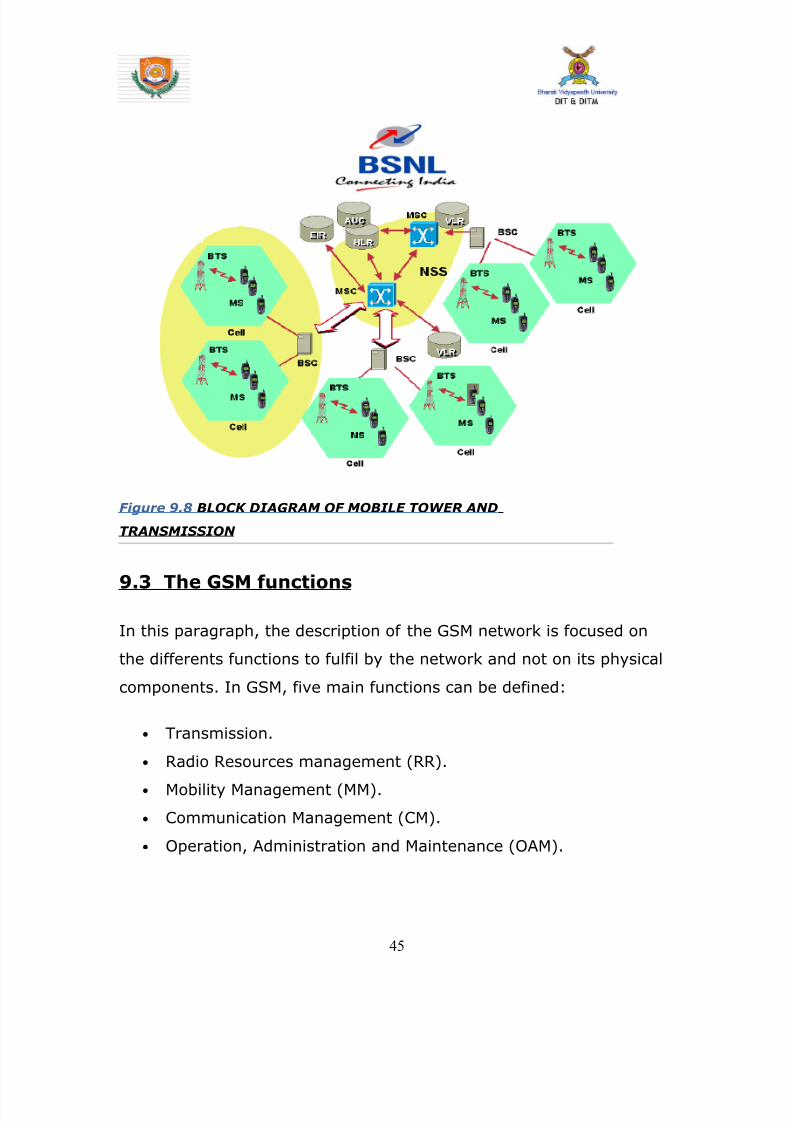
8142019 Dipti Report
httpslidepdfcomreaderfulldipti-report 4662
94 GSM Frequencies
In principle the GSM system can be implemented in any frequency
band However there are several bands where GSM terminals are or
will shortly be available Furthermore GSM terminals may incorporate
one or more of the GSM frequency bands listed below to facilitate
roaming on a global basis
Frequency Range
GSM400 4504 - 4576 MHz paired with 4604 - 4676
MHz
or
4788 - 486 MHz paired with 4888 - 496 MHz
GSM 850 824 - 849 MHz paired with 869 - 894 MHz
GSM900 880 - 915 MHz paired with 925 - 960 MHz
GSM1800 1710 - 1785 MHz paired with 1805 - 1880 MHz
GSM1900 1850 - 1910 MHz paired with 1930 - 1990 MHz
95 Frequency allocation
Two frequency bands of 25 Mhz each one have been allocated for the
GSM system
bull The band 890-915 Mhz has been allocated for the uplink
direction (transmitting from the mobile station to the base
station)
46
8142019 Dipti Report
httpslidepdfcomreaderfulldipti-report 4762
bull The band 935-960 Mhz has been allocated for the downlink
direction (transmitting from the base station to the mobile
station)
But not all the countries can use the whole GSM frequency bands
This is due principally to military reasons and to the existence of
previous analog systems using part of the two 25 Mhz frequency
bands
Traffic is measured in ERLANG
BSC Capacity is 1min 5000 ERLANG
Now in 3G in respect of BSC MSC
RNC(Radio Network Control) is used
CHAPTER 10
47
8142019 Dipti Report
httpslidepdfcomreaderfulldipti-report 4862
INTRODUCTION
MAIN DISTRIBUTION FRAME (MDF)
The main distribution frame acts as a link between the
exchange indoor and the exchange outdoor It not only
connects the exchange with the subscriber but also protects
the exchange from environmental hazards such as lightning
strike
There are two sides in a MDF -
101 Line side - The line side belongs to the outdoor The
subscriber is connected to the exchange via the MDF In the
line side there are analog connections
This side of the exchange consists of verticals Each vertical
has 100 trans and receive pairs connected to it ie 100
subscribers are connected to the exchange via one vertical
Each vertical corresponds to a particular pillar The line wires
emanating from the verticals are connected to a cabinet
from where it is taken to a pillar which then is connected to
48
8142019 Dipti Report
httpslidepdfcomreaderfulldipti-report 4962
a distribution pole (DP) From here the lines are distributed
to the subscribers
For line testing on the line side the dial tone is tested on the
vertical first If it is found to be ok then the testing is carried
forward to the cabinet From here line wires are carried
forward in a cluster of around 100 pairs to the pillar A pillar
is usually located in the central part of an area where the
pillar is established so that distribution is convenient and
less expensive One distribution pole is set up to provide
connection to around 15 to 20 homes From here the
subscribers are directly connected
102 Exchange side - Exchange side belongs to the
exchange On the exchange side of the MDF the connections
are DigitalThe connection between the
exchange and the subscriber is made in various stages On
the exchange side the MDF is directly connected to the DLU
in the SN (Switching Network) In the MDF the two sides
49
8142019 Dipti Report
httpslidepdfcomreaderfulldipti-report 5062
are connected through a jumper wire The line testing for
the exchange is done first here using a dial tone checker
For rectifying errors each subscriber is assigned an
Equipment Number (NE) This number is the identification
mark of the subscriber for the exchange It represents the
location in the DLU from where the connection is provided
The DLU is then connected to the LTG (Line Trunk Groups)
from here the switching network is connected
CHAPTER 11
50
8142019 Dipti Report
httpslidepdfcomreaderfulldipti-report 5162
INTRODUCTION
THE POWER PLANT
Power Plant is the main part of an Exchange It provide uninterrupted
power to the exchange continuously it also plays the role of converting
AC power to DC power
The arrangement made has one active and two standby systems for
supplying power This makes the system extremely reliable even in the
areas with acute power shortage Options like maintenance free
batteries (VRLA) also make it cost effective
There are three supply options in the power plant
bull The AC mains
bull The Value Regulated Lead Acid battery set
bull The engine alternator
111 The AC Mains
The exchange requires a constant supply voltage of 48V (DC) in the
running condition So the voltage obtained from which is 66 KV needs
51
8142019 Dipti Report
httpslidepdfcomreaderfulldipti-report 5262
to be stepped down and rectified to DC voltage This function is
performed by the float rectifier unit
112 The Battery Set
There are two sets of VRLA batteries which are maintenance free
batteries Each set is capable of providing the required 48V DC supply
and have a capacity of 4000 AH (Ampere Hour) They are named as
set A and set B One set is active while the other set is available for
standby In case AC mains power is on both the sets of batteries get
charged As soon as there is a power cut the load gets switched over
to the battery set and one of the sets gets active while the other is
available for standby But even this source cannot be trusted for very
long durations as each set is capable of sustaining the load only for
about 3 hours So we need another alternative to provide a fool proof
system This calls for the use of the engine alternator
1113 The Engine Alternator
Usually the battery set is always kept for standby operation In case
there is a power cut the battery set operates hardly for 5 to 10
minutes which is the time taken for the alternator to start
There are also two sets of generators which are rated as follows
bull 66 KV415V voltage rating with moisture absorber
bull 200 KVA power rating
52
8142019 Dipti Report
httpslidepdfcomreaderfulldipti-report 5362
CHAPTER 12
INTRODUCTION
OPERATION AND MAINTENANCE TERMINAL
On the basis of Operation and maintenance terminal Function it has
been grouped into following categories
121 OPERATING FUNCTIONS
1 Charging function
2 Continuous connectivity management
3 Memory management of Translator
122 SUPERVISION FUNCTIONS
1 Circuit tests
2 Line and subscriber set tests
3 Load and traffic observation
123 MAINTENANCE FUNCTIONS
1 Maintenance of exchange control unit memories
2 Fault location and trouble-shooting aid function
3 Telephone equipment position
53
8142019 Dipti Report
httpslidepdfcomreaderfulldipti-report 5462
CHAPTER 13
INTRODUCTION
PULSE CODE MODULATION
PCM is a process which converts a continuous analog signal into digital
signals It is a Multichannel transmission technique that explores the
advantage of digital transmission over analog transmission It only
realizes the advantages of improved transmission limits greater noise
immunity lesser distortion of dial pulses but also economy
Converting continuous analog signal into digital signals is
carried out in three stages-
131 Sampling- Sampling is a periodical
measurement of the value of the analog signal A sampled
data contains all the information of the signal if the
sampling frequency is at least twice the highest frequency
of the signal to be sampled As the signals in telephony are
band limited to 300-3400Hz a sampling are frequency of
8000Hz ie every 125 micro seconds is sufficient
54
8142019 Dipti Report
httpslidepdfcomreaderfulldipti-report 5562
132 Quantizing - representation of their amplitude is forced to
take certain value To ensure that the ratio between signal amplitude
and errors introduced by quantized and encoded (companding) law is
applied
133 Encoding - PAM signals are quantized and encoded into 8
bit symmetrical binary code and transmitted on line during the time
slot allotted to that channel as PCM signals
At the receive side these PCM signals are decoded into PAM
signals and smoothed out by passing through low-pass filters to filters
to get back originals signals
This PCM system can support 30 simultaneous telephone conversation
and optionally 8 telegraphteleprinter channels on one line Individual
channels have a transmission speed of 64 Kbitss and the total
transmission rate for all 32 channels in the system is 2048 Kbitss
55
8142019 Dipti Report
httpslidepdfcomreaderfulldipti-report 5662
CHAPTER 14
INTRODUCTION
SWITCHING
There are two types of switching namely CIRCUIT Switching and
PACKET Switching
141 CIRCUIT SWITCHING - A circuit switching network is onethat establishes a dedicated circuit between nodes and terminals
before the users may communicate Each circuit that is dedicated
cannot be used by other callers until the circuit is released and a new
connection is set up Even if no actual communication is taking place in
a dedicated circuit then that channel still remains unavailable to other
users Channels that are available for new calls to be set up are said to
be idle Early telephone exchanges are a suitable example of circuitswitching
142 PACKET SWITCHING - Packet switching is a
communications paradigm in which packets are routed between nodes
over data links shared with other traffic This contrasts with the other
56
8142019 Dipti Report
httpslidepdfcomreaderfulldipti-report 5762
principal paradigm circuit switching which sets up a dedicated
connection between the two nodes for their exclusive use for the
duration of the communication Packet switching is used to optimize
the use of the channel capacity available in a network to minimize the
transmission latency (ie the time it takes for data to pass across the
network) and to increase robustness of communication
143 Circuit Switching vs Packet
Switching
In principle circuit switching and packet switching both are used in
high-capacity networks In circuit-switched networks network
resources are static set in ldquocopperrdquo if you will from the sender to
receiver before the start of the transfer thus creating a ldquocircuitrdquo The
resources remain dedicated to the circuit during the entire transfer and
the entire message follows the same path In packet-switched
networks the message is broken into packets each of which can take
a different route to the destination where the packets are recompiled
into the original message Circuit switching contrasts with packet
switching which splits traffic data (for instance digital representation
of sound or computer data) into chunks called packets that are
routed over a shared network Packet switching networks do not
require a circuit to be established and allow many pairs of nodes to
communicate almost simultaneously over the same channel Each
57
8142019 Dipti Report
httpslidepdfcomreaderfulldipti-report 5862
packet is individually addressed precluding the need for a dedicated
path to help the packet find its way to its destination
CHAPTER 15
CONCLUSION
This Practical Training has given me an opportunity to know about various
technologies working behind in todayrsquos advanced world of telecommunication
All those that we read in our Book only theoretically by this training I observe all
those practically I come across different units in telecom exchange like
E10BOCBEWSD Mobile (GSM) BSC and BTS MDF and Power Plant
and Broadband I not only watch those equipment but also know about those
there working there functions and also how by work to provide us facility of
telecomI am very grateful to those persons who helped directly amp
indirectly in the successful completion of this practical training and this will
surely be fruitful in future
58
8142019 Dipti Report
httpslidepdfcomreaderfulldipti-report 5962
CHAPTER 16
APPENDIX
161 Loading statement of Jamshedpur OCB-283Capacity of the TAXndash22K Loading ndash 5915
Station IC OG Between Total PCM
Arra Nil Nil 30 1
Ambala Nil Nil 30 1
Bangalore Nil Nil 61 2
Bhagalpur Nil Nil 60 2
Chennai Nil Nil 30 1
Cuttack Nil Nil 184 6
Daltengung Nil Nil 30 1
Darbhanga Nil Nil 60 2
Delhi bsnl Nil Nil 122 4Delhi mtnl Nil Nil 91 3
Dhanbad Nil Nil 122 4
Dumka Nil Nil 30 1
Ericson1 Nil Nil 494 16
Ericson2 Ni Nil 122 4
Gaya Nil Nil 61 2
Hajipur Nil Nil 30 1
Hazaribag Nil Nil 91 3
Hyderabad Nil Nil 123 4
Kolkata Nil Nil 246 8
Kharagpur Nil Nil 91 3
Katihar Nil Nil 30 1
Lucknow Nil Nil 90 3
Mumbai bsnl Nil Nil 61 2
Mumbai mtnl Nil Nil 62 2
59
8142019 Dipti Report
httpslidepdfcomreaderfulldipti-report 6062
Munger Nil Nil 30 1
Muzafferpur Nil Nil 61 2
Nortel Nil Nil 587 19
Purulia Nil Nil 61 2
Patna Nil Nil 151 5
Patliputr Nil Nil 122 8
Raurkela Nil Nil 91 3
Ranchi 15 45 680 24
Sasaram Nil Nil 30 1
Saharsa Nil Nil 30 1Sakla Nil Nil 153 5
Sambalpur Nil Nil 30 1
Tarang Nil Nil 154 5
Baripada Nil Nil 60 2
MSCA Nil Nil 309 10
Msc bokaro Nil Nil 618 20
Total 15 45 5518 182
162 OCB ndash 283 MAIN TELEPHONE EXCHANGES
EXCHANGE CAPACITY PCM
Main Exchange 12k -
Rsu Telco 11256 15
Rsu Adityapur 3k -
Rsu Sidhgora 4k 12
Rsu Mani fit 4256k 11
Rsu Govindpur 2k 10
Rsu Tatanagar 4256k 14
Rsu Parsudih 4k 11
Dlcjsr 6rt -Dlc Parsudih 2rt -
DlcTelco 1rt -
RsuKharkai 1k -
Ghatsila 6585 12
Bahragora 6594 3
Chaibasa 6582 12
60
8142019 Dipti Report
httpslidepdfcomreaderfulldipti-report 6162
Chakardharpur 6587 5
Manoharpur 6593 2
Saraikela 6597 7
Chandil 6591 -
Jhinkpani 6589 -
Jagannathpur 6588 -
Giriburu 6596 4
Nowamundi 6596 5
Kharzwara 6583 -
163 PHONE CODES AND THEIR EXCHANGE CODE
61
PHONE CODE EXCHANGE
2758 JSR
2756 JSR
2421 JSR
243 JSR
244 JSR
248 JSR
222 JSR223 JSR
265 SNK
240 ADR
220 ADR
2370-3 ADR
2380-3 ADR
2386-87 GMR
246 amp 236 MNG
29 7 DIGIT WJSR
2270 GVP2277 GVP
2290-95 TAT
2296 PSD
230-231 KDM
234 GOL
226228 TLC
221 SDG
232 LIC
2249 KHL
8142019 Dipti Report
httpslidepdfcomreaderfulldipti-report 6262
8142019 Dipti Report
httpslidepdfcomreaderfulldipti-report 5662
CHAPTER 14
INTRODUCTION
SWITCHING
There are two types of switching namely CIRCUIT Switching and
PACKET Switching
141 CIRCUIT SWITCHING - A circuit switching network is onethat establishes a dedicated circuit between nodes and terminals
before the users may communicate Each circuit that is dedicated
cannot be used by other callers until the circuit is released and a new
connection is set up Even if no actual communication is taking place in
a dedicated circuit then that channel still remains unavailable to other
users Channels that are available for new calls to be set up are said to
be idle Early telephone exchanges are a suitable example of circuitswitching
142 PACKET SWITCHING - Packet switching is a
communications paradigm in which packets are routed between nodes
over data links shared with other traffic This contrasts with the other
56
8142019 Dipti Report
httpslidepdfcomreaderfulldipti-report 5762
principal paradigm circuit switching which sets up a dedicated
connection between the two nodes for their exclusive use for the
duration of the communication Packet switching is used to optimize
the use of the channel capacity available in a network to minimize the
transmission latency (ie the time it takes for data to pass across the
network) and to increase robustness of communication
143 Circuit Switching vs Packet
Switching
In principle circuit switching and packet switching both are used in
high-capacity networks In circuit-switched networks network
resources are static set in ldquocopperrdquo if you will from the sender to
receiver before the start of the transfer thus creating a ldquocircuitrdquo The
resources remain dedicated to the circuit during the entire transfer and
the entire message follows the same path In packet-switched
networks the message is broken into packets each of which can take
a different route to the destination where the packets are recompiled
into the original message Circuit switching contrasts with packet
switching which splits traffic data (for instance digital representation
of sound or computer data) into chunks called packets that are
routed over a shared network Packet switching networks do not
require a circuit to be established and allow many pairs of nodes to
communicate almost simultaneously over the same channel Each
57
8142019 Dipti Report
httpslidepdfcomreaderfulldipti-report 5862
packet is individually addressed precluding the need for a dedicated
path to help the packet find its way to its destination
CHAPTER 15
CONCLUSION
This Practical Training has given me an opportunity to know about various
technologies working behind in todayrsquos advanced world of telecommunication
All those that we read in our Book only theoretically by this training I observe all
those practically I come across different units in telecom exchange like
E10BOCBEWSD Mobile (GSM) BSC and BTS MDF and Power Plant
and Broadband I not only watch those equipment but also know about those
there working there functions and also how by work to provide us facility of
telecomI am very grateful to those persons who helped directly amp
indirectly in the successful completion of this practical training and this will
surely be fruitful in future
58
8142019 Dipti Report
httpslidepdfcomreaderfulldipti-report 5962
CHAPTER 16
APPENDIX
161 Loading statement of Jamshedpur OCB-283Capacity of the TAXndash22K Loading ndash 5915
Station IC OG Between Total PCM
Arra Nil Nil 30 1
Ambala Nil Nil 30 1
Bangalore Nil Nil 61 2
Bhagalpur Nil Nil 60 2
Chennai Nil Nil 30 1
Cuttack Nil Nil 184 6
Daltengung Nil Nil 30 1
Darbhanga Nil Nil 60 2
Delhi bsnl Nil Nil 122 4Delhi mtnl Nil Nil 91 3
Dhanbad Nil Nil 122 4
Dumka Nil Nil 30 1
Ericson1 Nil Nil 494 16
Ericson2 Ni Nil 122 4
Gaya Nil Nil 61 2
Hajipur Nil Nil 30 1
Hazaribag Nil Nil 91 3
Hyderabad Nil Nil 123 4
Kolkata Nil Nil 246 8
Kharagpur Nil Nil 91 3
Katihar Nil Nil 30 1
Lucknow Nil Nil 90 3
Mumbai bsnl Nil Nil 61 2
Mumbai mtnl Nil Nil 62 2
59
8142019 Dipti Report
httpslidepdfcomreaderfulldipti-report 6062
Munger Nil Nil 30 1
Muzafferpur Nil Nil 61 2
Nortel Nil Nil 587 19
Purulia Nil Nil 61 2
Patna Nil Nil 151 5
Patliputr Nil Nil 122 8
Raurkela Nil Nil 91 3
Ranchi 15 45 680 24
Sasaram Nil Nil 30 1
Saharsa Nil Nil 30 1Sakla Nil Nil 153 5
Sambalpur Nil Nil 30 1
Tarang Nil Nil 154 5
Baripada Nil Nil 60 2
MSCA Nil Nil 309 10
Msc bokaro Nil Nil 618 20
Total 15 45 5518 182
162 OCB ndash 283 MAIN TELEPHONE EXCHANGES
EXCHANGE CAPACITY PCM
Main Exchange 12k -
Rsu Telco 11256 15
Rsu Adityapur 3k -
Rsu Sidhgora 4k 12
Rsu Mani fit 4256k 11
Rsu Govindpur 2k 10
Rsu Tatanagar 4256k 14
Rsu Parsudih 4k 11
Dlcjsr 6rt -Dlc Parsudih 2rt -
DlcTelco 1rt -
RsuKharkai 1k -
Ghatsila 6585 12
Bahragora 6594 3
Chaibasa 6582 12
60
8142019 Dipti Report
httpslidepdfcomreaderfulldipti-report 6162
Chakardharpur 6587 5
Manoharpur 6593 2
Saraikela 6597 7
Chandil 6591 -
Jhinkpani 6589 -
Jagannathpur 6588 -
Giriburu 6596 4
Nowamundi 6596 5
Kharzwara 6583 -
163 PHONE CODES AND THEIR EXCHANGE CODE
61
PHONE CODE EXCHANGE
2758 JSR
2756 JSR
2421 JSR
243 JSR
244 JSR
248 JSR
222 JSR223 JSR
265 SNK
240 ADR
220 ADR
2370-3 ADR
2380-3 ADR
2386-87 GMR
246 amp 236 MNG
29 7 DIGIT WJSR
2270 GVP2277 GVP
2290-95 TAT
2296 PSD
230-231 KDM
234 GOL
226228 TLC
221 SDG
232 LIC
2249 KHL
8142019 Dipti Report
httpslidepdfcomreaderfulldipti-report 6262

8142019 Dipti Report
httpslidepdfcomreaderfulldipti-report 5762
principal paradigm circuit switching which sets up a dedicated
connection between the two nodes for their exclusive use for the
duration of the communication Packet switching is used to optimize
the use of the channel capacity available in a network to minimize the
transmission latency (ie the time it takes for data to pass across the
network) and to increase robustness of communication
143 Circuit Switching vs Packet
Switching
In principle circuit switching and packet switching both are used in
high-capacity networks In circuit-switched networks network
resources are static set in ldquocopperrdquo if you will from the sender to
receiver before the start of the transfer thus creating a ldquocircuitrdquo The
resources remain dedicated to the circuit during the entire transfer and
the entire message follows the same path In packet-switched
networks the message is broken into packets each of which can take
a different route to the destination where the packets are recompiled
into the original message Circuit switching contrasts with packet
switching which splits traffic data (for instance digital representation
of sound or computer data) into chunks called packets that are
routed over a shared network Packet switching networks do not
require a circuit to be established and allow many pairs of nodes to
communicate almost simultaneously over the same channel Each
57
8142019 Dipti Report
httpslidepdfcomreaderfulldipti-report 5862
packet is individually addressed precluding the need for a dedicated
path to help the packet find its way to its destination
CHAPTER 15
CONCLUSION
This Practical Training has given me an opportunity to know about various
technologies working behind in todayrsquos advanced world of telecommunication
All those that we read in our Book only theoretically by this training I observe all
those practically I come across different units in telecom exchange like
E10BOCBEWSD Mobile (GSM) BSC and BTS MDF and Power Plant
and Broadband I not only watch those equipment but also know about those
there working there functions and also how by work to provide us facility of
telecomI am very grateful to those persons who helped directly amp
indirectly in the successful completion of this practical training and this will
surely be fruitful in future
58
8142019 Dipti Report
httpslidepdfcomreaderfulldipti-report 5962
CHAPTER 16
APPENDIX
161 Loading statement of Jamshedpur OCB-283Capacity of the TAXndash22K Loading ndash 5915
Station IC OG Between Total PCM
Arra Nil Nil 30 1
Ambala Nil Nil 30 1
Bangalore Nil Nil 61 2
Bhagalpur Nil Nil 60 2
Chennai Nil Nil 30 1
Cuttack Nil Nil 184 6
Daltengung Nil Nil 30 1
Darbhanga Nil Nil 60 2
Delhi bsnl Nil Nil 122 4Delhi mtnl Nil Nil 91 3
Dhanbad Nil Nil 122 4
Dumka Nil Nil 30 1
Ericson1 Nil Nil 494 16
Ericson2 Ni Nil 122 4
Gaya Nil Nil 61 2
Hajipur Nil Nil 30 1
Hazaribag Nil Nil 91 3
Hyderabad Nil Nil 123 4
Kolkata Nil Nil 246 8
Kharagpur Nil Nil 91 3
Katihar Nil Nil 30 1
Lucknow Nil Nil 90 3
Mumbai bsnl Nil Nil 61 2
Mumbai mtnl Nil Nil 62 2
59
8142019 Dipti Report
httpslidepdfcomreaderfulldipti-report 6062
Munger Nil Nil 30 1
Muzafferpur Nil Nil 61 2
Nortel Nil Nil 587 19
Purulia Nil Nil 61 2
Patna Nil Nil 151 5
Patliputr Nil Nil 122 8
Raurkela Nil Nil 91 3
Ranchi 15 45 680 24
Sasaram Nil Nil 30 1
Saharsa Nil Nil 30 1Sakla Nil Nil 153 5
Sambalpur Nil Nil 30 1
Tarang Nil Nil 154 5
Baripada Nil Nil 60 2
MSCA Nil Nil 309 10
Msc bokaro Nil Nil 618 20
Total 15 45 5518 182
162 OCB ndash 283 MAIN TELEPHONE EXCHANGES
EXCHANGE CAPACITY PCM
Main Exchange 12k -
Rsu Telco 11256 15
Rsu Adityapur 3k -
Rsu Sidhgora 4k 12
Rsu Mani fit 4256k 11
Rsu Govindpur 2k 10
Rsu Tatanagar 4256k 14
Rsu Parsudih 4k 11
Dlcjsr 6rt -Dlc Parsudih 2rt -
DlcTelco 1rt -
RsuKharkai 1k -
Ghatsila 6585 12
Bahragora 6594 3
Chaibasa 6582 12
60
8142019 Dipti Report
httpslidepdfcomreaderfulldipti-report 6162
Chakardharpur 6587 5
Manoharpur 6593 2
Saraikela 6597 7
Chandil 6591 -
Jhinkpani 6589 -
Jagannathpur 6588 -
Giriburu 6596 4
Nowamundi 6596 5
Kharzwara 6583 -
163 PHONE CODES AND THEIR EXCHANGE CODE
61
PHONE CODE EXCHANGE
2758 JSR
2756 JSR
2421 JSR
243 JSR
244 JSR
248 JSR
222 JSR223 JSR
265 SNK
240 ADR
220 ADR
2370-3 ADR
2380-3 ADR
2386-87 GMR
246 amp 236 MNG
29 7 DIGIT WJSR
2270 GVP2277 GVP
2290-95 TAT
2296 PSD
230-231 KDM
234 GOL
226228 TLC
221 SDG
232 LIC
2249 KHL
8142019 Dipti Report
httpslidepdfcomreaderfulldipti-report 6262
8142019 Dipti Report
httpslidepdfcomreaderfulldipti-report 5862
packet is individually addressed precluding the need for a dedicated
path to help the packet find its way to its destination
CHAPTER 15
CONCLUSION
This Practical Training has given me an opportunity to know about various
technologies working behind in todayrsquos advanced world of telecommunication
All those that we read in our Book only theoretically by this training I observe all
those practically I come across different units in telecom exchange like
E10BOCBEWSD Mobile (GSM) BSC and BTS MDF and Power Plant
and Broadband I not only watch those equipment but also know about those
there working there functions and also how by work to provide us facility of
telecomI am very grateful to those persons who helped directly amp
indirectly in the successful completion of this practical training and this will
surely be fruitful in future
58
8142019 Dipti Report
httpslidepdfcomreaderfulldipti-report 5962
CHAPTER 16
APPENDIX
161 Loading statement of Jamshedpur OCB-283Capacity of the TAXndash22K Loading ndash 5915
Station IC OG Between Total PCM
Arra Nil Nil 30 1
Ambala Nil Nil 30 1
Bangalore Nil Nil 61 2
Bhagalpur Nil Nil 60 2
Chennai Nil Nil 30 1
Cuttack Nil Nil 184 6
Daltengung Nil Nil 30 1
Darbhanga Nil Nil 60 2
Delhi bsnl Nil Nil 122 4Delhi mtnl Nil Nil 91 3
Dhanbad Nil Nil 122 4
Dumka Nil Nil 30 1
Ericson1 Nil Nil 494 16
Ericson2 Ni Nil 122 4
Gaya Nil Nil 61 2
Hajipur Nil Nil 30 1
Hazaribag Nil Nil 91 3
Hyderabad Nil Nil 123 4
Kolkata Nil Nil 246 8
Kharagpur Nil Nil 91 3
Katihar Nil Nil 30 1
Lucknow Nil Nil 90 3
Mumbai bsnl Nil Nil 61 2
Mumbai mtnl Nil Nil 62 2
59
8142019 Dipti Report
httpslidepdfcomreaderfulldipti-report 6062
Munger Nil Nil 30 1
Muzafferpur Nil Nil 61 2
Nortel Nil Nil 587 19
Purulia Nil Nil 61 2
Patna Nil Nil 151 5
Patliputr Nil Nil 122 8
Raurkela Nil Nil 91 3
Ranchi 15 45 680 24
Sasaram Nil Nil 30 1
Saharsa Nil Nil 30 1Sakla Nil Nil 153 5
Sambalpur Nil Nil 30 1
Tarang Nil Nil 154 5
Baripada Nil Nil 60 2
MSCA Nil Nil 309 10
Msc bokaro Nil Nil 618 20
Total 15 45 5518 182
162 OCB ndash 283 MAIN TELEPHONE EXCHANGES
EXCHANGE CAPACITY PCM
Main Exchange 12k -
Rsu Telco 11256 15
Rsu Adityapur 3k -
Rsu Sidhgora 4k 12
Rsu Mani fit 4256k 11
Rsu Govindpur 2k 10
Rsu Tatanagar 4256k 14
Rsu Parsudih 4k 11
Dlcjsr 6rt -Dlc Parsudih 2rt -
DlcTelco 1rt -
RsuKharkai 1k -
Ghatsila 6585 12
Bahragora 6594 3
Chaibasa 6582 12
60
8142019 Dipti Report
httpslidepdfcomreaderfulldipti-report 6162
Chakardharpur 6587 5
Manoharpur 6593 2
Saraikela 6597 7
Chandil 6591 -
Jhinkpani 6589 -
Jagannathpur 6588 -
Giriburu 6596 4
Nowamundi 6596 5
Kharzwara 6583 -
163 PHONE CODES AND THEIR EXCHANGE CODE
61
PHONE CODE EXCHANGE
2758 JSR
2756 JSR
2421 JSR
243 JSR
244 JSR
248 JSR
222 JSR223 JSR
265 SNK
240 ADR
220 ADR
2370-3 ADR
2380-3 ADR
2386-87 GMR
246 amp 236 MNG
29 7 DIGIT WJSR
2270 GVP2277 GVP
2290-95 TAT
2296 PSD
230-231 KDM
234 GOL
226228 TLC
221 SDG
232 LIC
2249 KHL
8142019 Dipti Report
httpslidepdfcomreaderfulldipti-report 6262
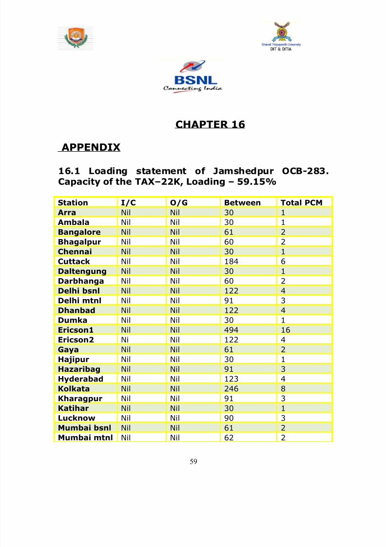
8142019 Dipti Report
httpslidepdfcomreaderfulldipti-report 5962
CHAPTER 16
APPENDIX
161 Loading statement of Jamshedpur OCB-283Capacity of the TAXndash22K Loading ndash 5915
Station IC OG Between Total PCM
Arra Nil Nil 30 1
Ambala Nil Nil 30 1
Bangalore Nil Nil 61 2
Bhagalpur Nil Nil 60 2
Chennai Nil Nil 30 1
Cuttack Nil Nil 184 6
Daltengung Nil Nil 30 1
Darbhanga Nil Nil 60 2
Delhi bsnl Nil Nil 122 4Delhi mtnl Nil Nil 91 3
Dhanbad Nil Nil 122 4
Dumka Nil Nil 30 1
Ericson1 Nil Nil 494 16
Ericson2 Ni Nil 122 4
Gaya Nil Nil 61 2
Hajipur Nil Nil 30 1
Hazaribag Nil Nil 91 3
Hyderabad Nil Nil 123 4
Kolkata Nil Nil 246 8
Kharagpur Nil Nil 91 3
Katihar Nil Nil 30 1
Lucknow Nil Nil 90 3
Mumbai bsnl Nil Nil 61 2
Mumbai mtnl Nil Nil 62 2
59
8142019 Dipti Report
httpslidepdfcomreaderfulldipti-report 6062
Munger Nil Nil 30 1
Muzafferpur Nil Nil 61 2
Nortel Nil Nil 587 19
Purulia Nil Nil 61 2
Patna Nil Nil 151 5
Patliputr Nil Nil 122 8
Raurkela Nil Nil 91 3
Ranchi 15 45 680 24
Sasaram Nil Nil 30 1
Saharsa Nil Nil 30 1Sakla Nil Nil 153 5
Sambalpur Nil Nil 30 1
Tarang Nil Nil 154 5
Baripada Nil Nil 60 2
MSCA Nil Nil 309 10
Msc bokaro Nil Nil 618 20
Total 15 45 5518 182
162 OCB ndash 283 MAIN TELEPHONE EXCHANGES
EXCHANGE CAPACITY PCM
Main Exchange 12k -
Rsu Telco 11256 15
Rsu Adityapur 3k -
Rsu Sidhgora 4k 12
Rsu Mani fit 4256k 11
Rsu Govindpur 2k 10
Rsu Tatanagar 4256k 14
Rsu Parsudih 4k 11
Dlcjsr 6rt -Dlc Parsudih 2rt -
DlcTelco 1rt -
RsuKharkai 1k -
Ghatsila 6585 12
Bahragora 6594 3
Chaibasa 6582 12
60
8142019 Dipti Report
httpslidepdfcomreaderfulldipti-report 6162
Chakardharpur 6587 5
Manoharpur 6593 2
Saraikela 6597 7
Chandil 6591 -
Jhinkpani 6589 -
Jagannathpur 6588 -
Giriburu 6596 4
Nowamundi 6596 5
Kharzwara 6583 -
163 PHONE CODES AND THEIR EXCHANGE CODE
61
PHONE CODE EXCHANGE
2758 JSR
2756 JSR
2421 JSR
243 JSR
244 JSR
248 JSR
222 JSR223 JSR
265 SNK
240 ADR
220 ADR
2370-3 ADR
2380-3 ADR
2386-87 GMR
246 amp 236 MNG
29 7 DIGIT WJSR
2270 GVP2277 GVP
2290-95 TAT
2296 PSD
230-231 KDM
234 GOL
226228 TLC
221 SDG
232 LIC
2249 KHL
8142019 Dipti Report
httpslidepdfcomreaderfulldipti-report 6262
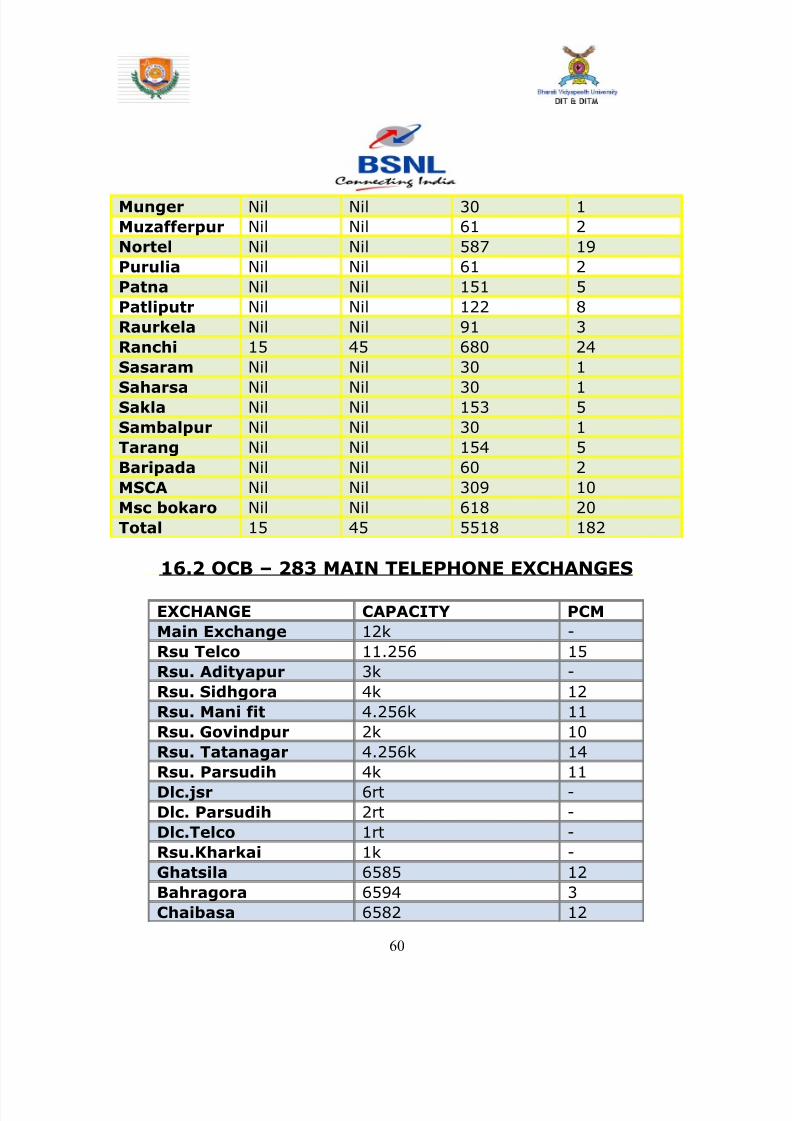
8142019 Dipti Report
httpslidepdfcomreaderfulldipti-report 6062
Munger Nil Nil 30 1
Muzafferpur Nil Nil 61 2
Nortel Nil Nil 587 19
Purulia Nil Nil 61 2
Patna Nil Nil 151 5
Patliputr Nil Nil 122 8
Raurkela Nil Nil 91 3
Ranchi 15 45 680 24
Sasaram Nil Nil 30 1
Saharsa Nil Nil 30 1Sakla Nil Nil 153 5
Sambalpur Nil Nil 30 1
Tarang Nil Nil 154 5
Baripada Nil Nil 60 2
MSCA Nil Nil 309 10
Msc bokaro Nil Nil 618 20
Total 15 45 5518 182
162 OCB ndash 283 MAIN TELEPHONE EXCHANGES
EXCHANGE CAPACITY PCM
Main Exchange 12k -
Rsu Telco 11256 15
Rsu Adityapur 3k -
Rsu Sidhgora 4k 12
Rsu Mani fit 4256k 11
Rsu Govindpur 2k 10
Rsu Tatanagar 4256k 14
Rsu Parsudih 4k 11
Dlcjsr 6rt -Dlc Parsudih 2rt -
DlcTelco 1rt -
RsuKharkai 1k -
Ghatsila 6585 12
Bahragora 6594 3
Chaibasa 6582 12
60
8142019 Dipti Report
httpslidepdfcomreaderfulldipti-report 6162
Chakardharpur 6587 5
Manoharpur 6593 2
Saraikela 6597 7
Chandil 6591 -
Jhinkpani 6589 -
Jagannathpur 6588 -
Giriburu 6596 4
Nowamundi 6596 5
Kharzwara 6583 -
163 PHONE CODES AND THEIR EXCHANGE CODE
61
PHONE CODE EXCHANGE
2758 JSR
2756 JSR
2421 JSR
243 JSR
244 JSR
248 JSR
222 JSR223 JSR
265 SNK
240 ADR
220 ADR
2370-3 ADR
2380-3 ADR
2386-87 GMR
246 amp 236 MNG
29 7 DIGIT WJSR
2270 GVP2277 GVP
2290-95 TAT
2296 PSD
230-231 KDM
234 GOL
226228 TLC
221 SDG
232 LIC
2249 KHL
8142019 Dipti Report
httpslidepdfcomreaderfulldipti-report 6262
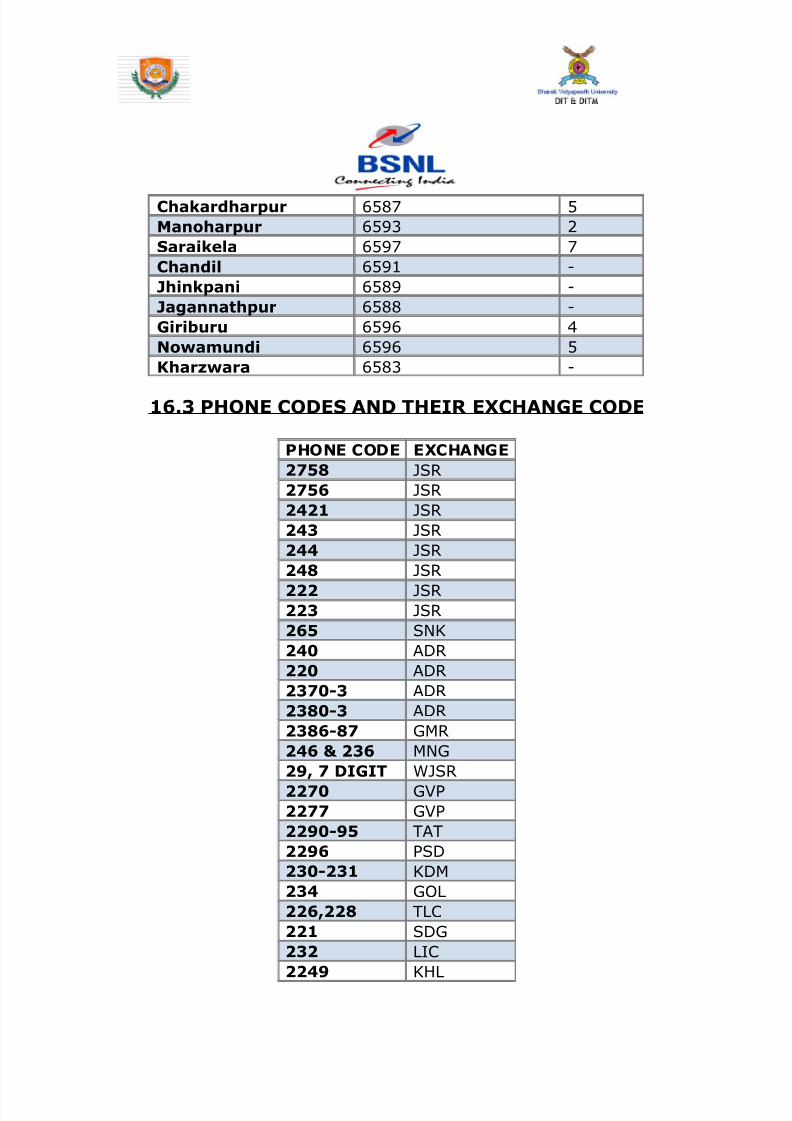
8142019 Dipti Report
httpslidepdfcomreaderfulldipti-report 6262