8310 pm revd 011907 - goodsononline.com.au · scanteam 8310/pm series programming manual use this...
TRANSCRIPT
MICR Check Reader
Programming Manual

Disclaimer UIC reserves the right to make changes in specifications and other information contained in this document without prior notice, and the user should in all cases consult UIC to determine whether any such changes have been made. The information in this publication does not represent a commitment on the part of UIC. UIC shall not be liable for technical or editorial errors or omissions contained herein; nor for incidental or consequential damages resulting from the furnishing, performance, or use of this material. This document contains proprietary information which is protected by copyright. All rights are reserved. No part of this document may be photocopied, reproduced, or translated into another language without the prior written consent of UIC. © 2007 Uniform Industrial Corp. All rights reserved.
Web Address: http://www.uicusa.com
1
SCANTEAM 8310/PM Series Programming Manual
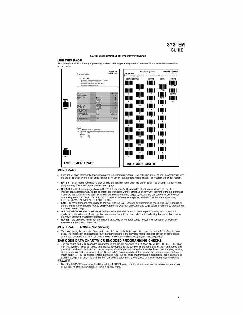
USE THIS PAGE As a general overview of the programming manual. The programming manual consists of two basic components as shown below.
MENU PAGE • Each menu page represents one section of the programming manual. Use individual menu pages in combination with
the bar code chart on the back page foldout, or MICR encoded programming checks, to program the check reader.
• ENTER – Each menu page has its own unique ENTER bar code; scan this bar code or feed through the equivalent programming check to activate desired menu page.
• DEFAULT – Most menu pages have a DEFAULT bar code/MICR encoded check which allows the user to independently default menu pages to asterisked (*) values without affecting, in any way, the rest of the programming menu. Default values can be easily selected from the desired menu pages by reading the bar code or MICR encoded check sequence ENTER, DEFAULT, EXIT. Individual defaults for a specific selection can be made by reading ENTER, ROMAN NUMERAL, DEFAULT, EXIT.
• EXIT – To move from one menu page to another, read the EXIT bar code or programming check. The EXIT bar code or programming check must be read to end programming selection on each menu page before beginning to program on a different menu page.
• SELECTIONS/VARIABLES – Lists all of the options available on each menu page. Following each option are symbols in shaded areas. These symbols correspond to both the bar codes on the adjoining bar code chart and to the MICR encoded programming checks.
• NOTES – are provided to call out any unusual situations and/or refer you to necessary information or examples elsewhere in the menu or manual.
MENU PAGE FACING (Not Shown) • The page facing the menu is often used to supplement or clarify the material presented on the front of each menu
page. The information and examples found here are specific to the individual menu page and contain, in some cases, charts and diagrams that must be used in order to determine the correct programming sequence.
BAR CODE DATA CHART/MICR ENCODED PROGRAMMING CHECKS • The bar codes and MICR encoded programming checks are assigned to a ROMAN NUMERAL, DIGIT, LETTER or
YES/NO symbol. These bar codes and checks correspond to the symbols in shaded areas on the menu pages and are read in various combinations to enter programming sequences to the check reader. Bar codes and programming checks are meaningless unless an ENTER bar code/programming check from one of the menu pages is first read. When an ENTER bar code/programming check is read, the bar code chart/programming checks become specific to that menu page and remain so until the EXIT bar code/programming check is read or another menu page is selected.
ESCAPE • Scan the ESCAPE bar code or feed through the ESCAPE programming check to cancel the current programming
sequence. All other parameters will remain as they were.
SYSTEMGUIDE
Programming Menu
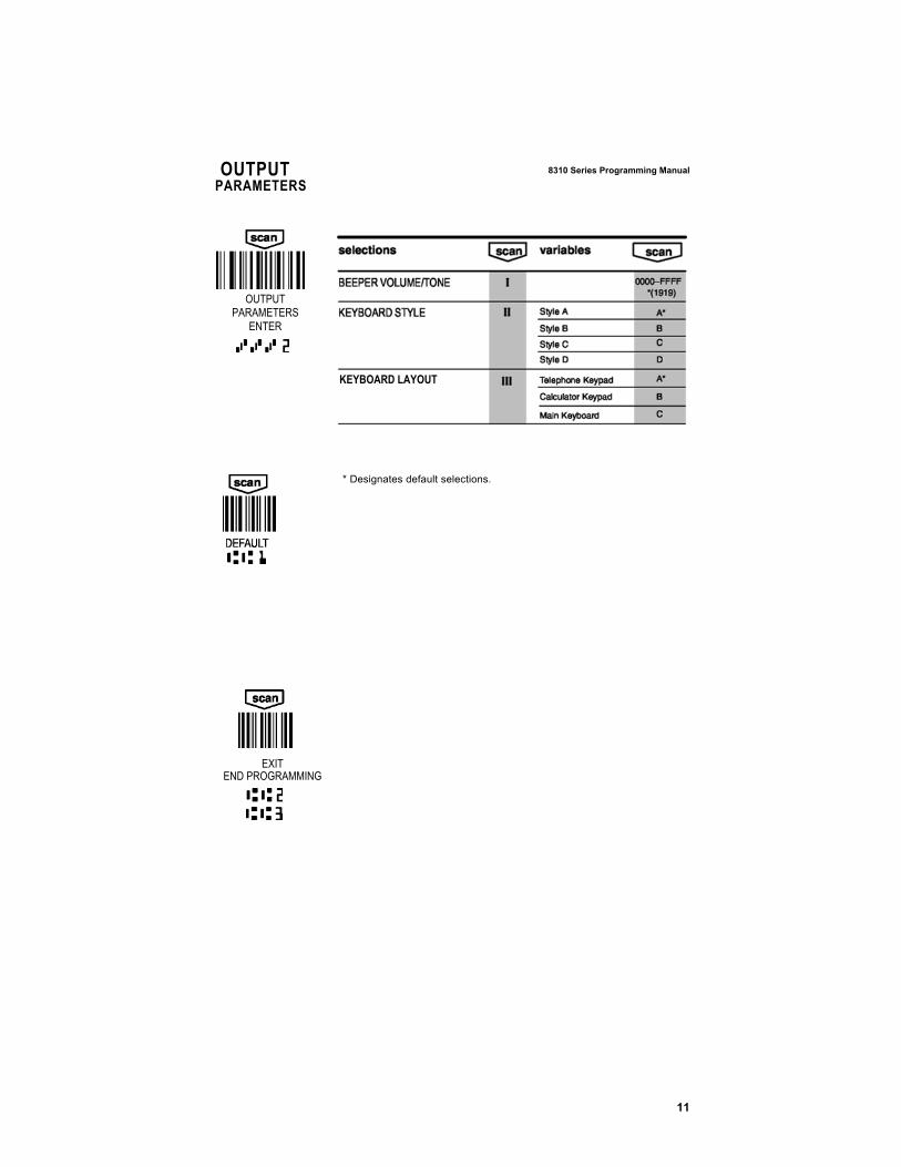
O U T P U T PARAMETERS
BEEPER VOLUME/TONE ~ 0000–FFFF
*(0190)
Primary Secondary
A* B
Tertiary C
KEYBOARD STYLE ~ ~
Quaternary D Layout 1 A* KEYBOARD
LAYOUT III ~ ~ ~ Layout 2 Layout 3
B C
INTERCHARACT-~ ~ ~ ER DELAY
x%ms
INTERFUNCTION ~ ~ ~ ~ x5ms *0000–999 DELAY INTERMESSAGE ~ ~ x5ms *0000–999 DELAY
Notes:
(1) * Designates DEFAULT selections. (2) The following are suggested Beeper Volume/Tone settings:
High 0190 Medium 00F0 Low 0080 Off 0000
SAMPLE MENU PAGE
USE THIS PAGE • To default this page to asterisked (*) values. • To set beeper volume and tone. • To program keyboard style and layout. • To program delay functions.
PROGRAMMING INSTRUCTIONS 8 3 1 0 S e r i e s P r o g r am m i ng M a n u a l
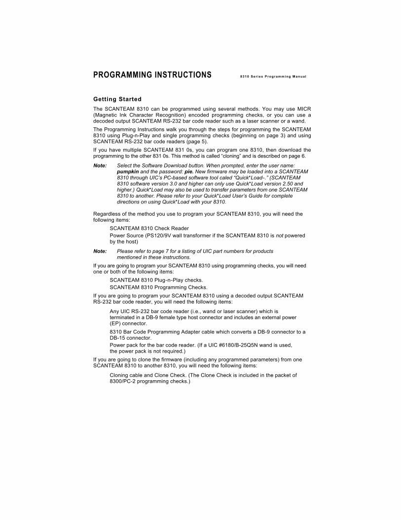
Getting Started The SCANTEAM 8310 can be programmed using several methods. You may use MICR (Magnetic Ink Character Recognition) encoded programming checks, or you can use a decoded output SCANTEAM RS-232 bar code reader such as a laser scanner or a wand. The Programming Instructions walk you through the steps for programming the SCANTEAM 8310 using Plug-n-Play and single programming checks (beginning on page 3) and using SCANTEAM RS-232 bar code readers (page 5). If you have multiple SCANTEAM 831 0s, you can program one 8310, then download the programming to the other 831 0s. This method is called “cloning” and is described on page 6.
Note: Select the Software Download button. When prompted, enter the user name: pumpkin and the password: pie. New firmware may be loaded into a SCANTEAM 8310 through UIC’s PC-based software tool caled “Quick*Load~.” (SCANTEAM 8310 software version 3.0 and higher can only use Quick*Load version 2.50 and higher.) Quick*Load may also be used to transfer parameters from one SCANTEAM 8310 to another. Please refer to your Quick*Load User’s Guide for complete directions on using Quick*Load with your 8310.
Regardless of the method you use to program your SCANTEAM 8310, you will need the following items:
� SCANTEAM 8310 Check Reader � Power Source (PS120/9V wall transformer if the SCANTEAM 8310 is not powered
by the host)
Note: Please refer to page 7 for a listing of UIC part numbers for products mentioned in these instructions.
If you are going to program your SCANTEAM 8310 using programming checks, you will need one or both of the following items:
� SCANTEAM 8310 Plug~n~Play checks. � SCANTEAM 8310 Programming Checks.
If you are going to program your SCANTEAM 8310 using a decoded output SCANTEAM RS-232 bar code reader, you will need the following items:
� Any UIC RS-232 bar code reader (i.e., wand or laser scanner) which is terminated in a DB-9 female type host connector and includes an external power (EP) connector.
� 8310 Bar Code Programming Adapter cable which converts a DB-9 connector to a DB-15 connector.
� Power pack for the bar code reader. (If a UIC #6180/B-25Q5N wand is used, the power pack is not required.)
If you are going to clone the firmware (including any programmed parameters) from one SCANTEAM 8310 to another 8310, you will need the following items:
� Cloning cable and Clone Check. (The Clone Check is included in the packet of 8300/PC-2 programming checks.)
3
8 3 1 0 S e r i e s P r o g r am m i ng M a n u a l PROGRAMMING INSTRUCTIONSContinued
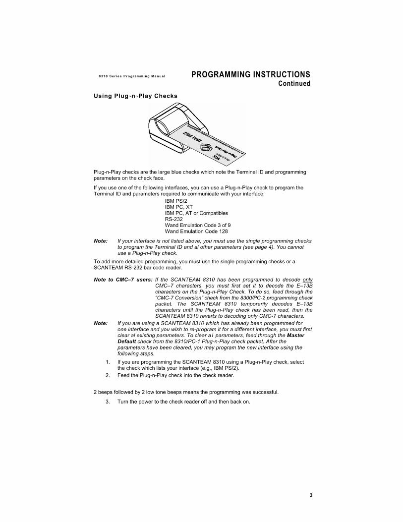
Using Plug~n~Play Checks
Plug-n-Play checks are the large blue checks which note the Terminal ID and programming parameters on the check face.
If you use one of the following interfaces, you can use a Plug-n-Play check to program the Terminal ID and parameters required to communicate with your interface:
IBM PS/2 IBM PC, XT IBM PC, AT or Compatibles RS-232 Wand Emulation Code 3 of 9 Wand Emulation Code 128
Note: If your interface is not listed above, you must use the single programming checks to program the Terminal ID and al other parameters (see page 4). You cannot use a Plug-n-Play check.
To add more detailed programming, you must use the single programming checks or a SCANTEAM RS-232 bar code reader.
Note to CMC–7 users: If the SCANTEAM 8310 has been programmed to decode only CMC–7 characters, you must first set it to decode the E–13B characters on the Plug-n-Play Check. To do so, feed through the “CMC-7 Conversion” check from the 8300/PC-2 programming check packet. The SCANTEAM 8310 temporarily decodes E–13B characters until the Plug-n-Play check has been read, then the SCANTEAM 8310 reverts to decoding only CMC-7 characters.
Note: If you are using a SCANTEAM 8310 which has already been programmed for one interface and you wish to re-program it for a different interface, you must first clear al existing parameters. To clear a l parameters, feed through the Master Default check from the 8310/PC-1 Plug-n-Play check packet. After the parameters have been cleared, you may program the new interface using the following steps.
1. If you are programming the SCANTEAM 8310 using a Plug-n-Play check, select the check which lists your interface (e.g., IBM PS/2).
2. Feed the Plug-n-Play check into the check reader.
2 beeps followed by 2 low tone beeps means the programming was successful.
3. Turn the power to the check reader off and then back on.
4
PROGRAMMING INSTRUCTIONS 8 3 1 0 S e r i e s P r o g r am m i ng M a n u a l
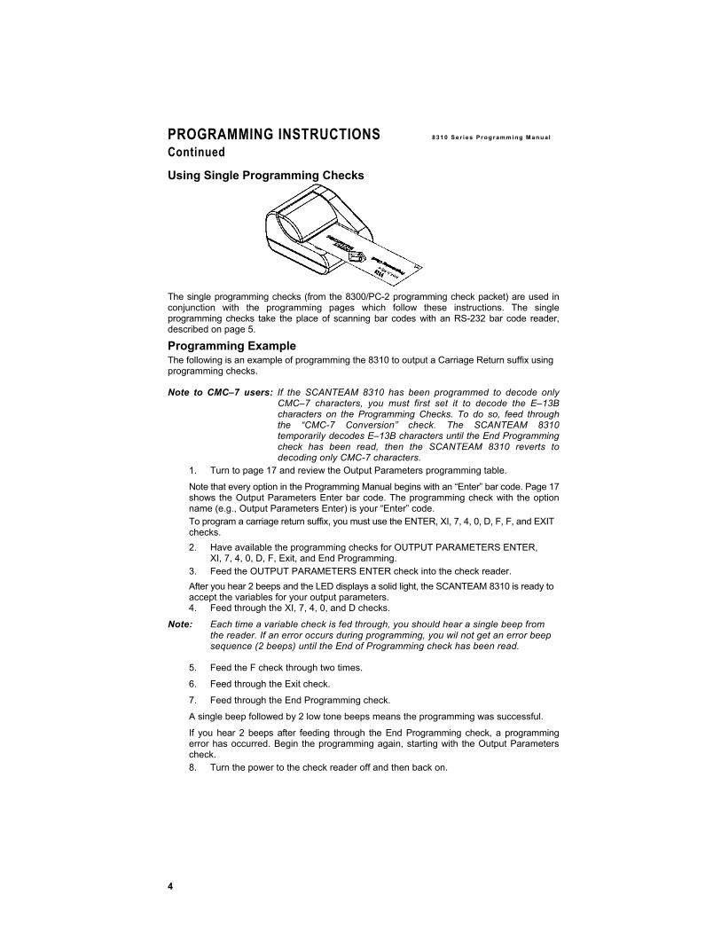
Using Single Programming Checks
The single programming checks (from the 8300/PC-2 programming check packet) are used in conjunction with the programming pages which follow these instructions. The single programming checks take the place of scanning bar codes with an RS-232 bar code reader, described on page 5.
Programming Example The following is an example of programming the 8310 to output a Carriage Return suffix using programming checks.
Note to CMC–7 users: If the SCANTEAM 8310 has been programmed to decode only CMC–7 characters, you must first set it to decode the E–13B characters on the Programming Checks. To do so, feed through the “CMC-7 Conversion” check. The SCANTEAM 8310 temporarily decodes E–13B characters until the End Programming check has been read, then the SCANTEAM 8310 reverts to decoding only CMC-7 characters.
1. Turn to page 17 and review the Output Parameters programming table.
Note that every option in the Programming Manual begins with an “Enter” bar code. Page 17 shows the Output Parameters Enter bar code. The programming check with the option name (e.g., Output Parameters Enter) is your “Enter” code. To program a carriage return suffix, you must use the ENTER, XI, 7, 4, 0, D, F, F, and EXIT checks. 2. Have available the programming checks for OUTPUT PARAMETERS ENTER,
XI, 7, 4, 0, D, F, Exit, and End Programming. 3. Feed the OUTPUT PARAMETERS ENTER check into the check reader. After you hear 2 beeps and the LED displays a solid light, the SCANTEAM 8310 is ready to accept the variables for your output parameters. 4. Feed through the XI, 7, 4, 0, and D checks.
Note: Each time a variable check is fed through, you should hear a single beep from the reader. If an error occurs during programming, you wil not get an error beep sequence (2 beeps) until the End of Programming check has been read.
5. Feed the F check through two times.
6. Feed through the Exit check.
7. Feed through the End Programming check.
A single beep followed by 2 low tone beeps means the programming was successful.
If you hear 2 beeps after feeding through the End Programming check, a programming error has occurred. Begin the programming again, starting with the Output Parameters check. 8. Turn the power to the check reader off and then back on.
Continued
PROGRAMMING INSTRUCTIONS 8 3 1 0 S e r i e s P r o g r am m i ng M a n u a l
Using the method just described, program the parameters necessary for your SCANTEAM 8310. Begin at page 9 if you need to program the Terminal ID, or at page 12 if you programmed your Terminal ID with a Plug-n-Play check.
Programming the SCANTEAM 8310 Using a SCANTEAM RS-232 Bar Code Reader
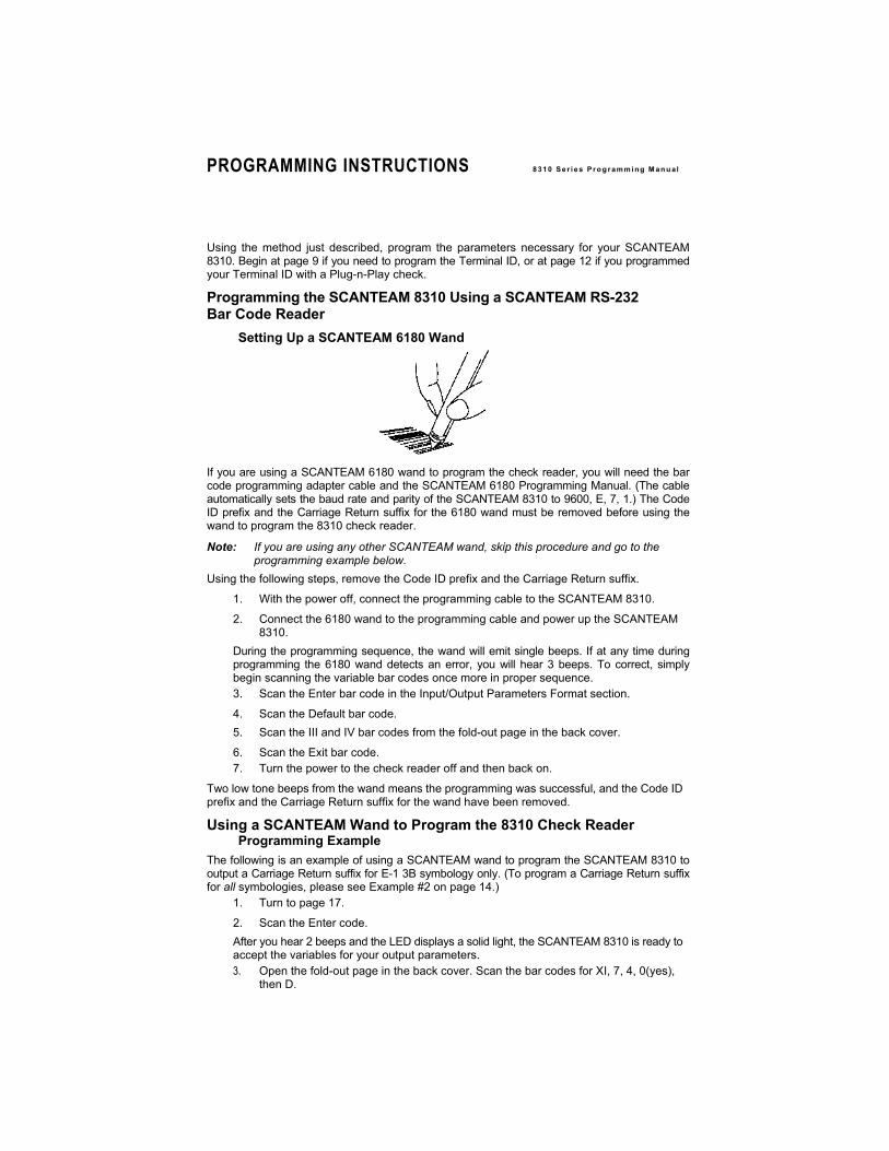
Setting Up a SCANTEAM 6180 Wand
If you are using a SCANTEAM 6180 wand to program the check reader, you will need the bar code programming adapter cable and the SCANTEAM 6180 Programming Manual. (The cable automatically sets the baud rate and parity of the SCANTEAM 8310 to 9600, E, 7, 1.) The Code ID prefix and the Carriage Return suffix for the 6180 wand must be removed before using the wand to program the 8310 check reader.
Note: If you are using any other SCANTEAM wand, skip this procedure and go to the programming example below.
Using the following steps, remove the Code ID prefix and the Carriage Return suffix.
1. With the power off, connect the programming cable to the SCANTEAM 8310.
2. Connect the 6180 wand to the programming cable and power up the SCANTEAM 8310.
During the programming sequence, the wand will emit single beeps. If at any time during programming the 6180 wand detects an error, you will hear 3 beeps. To correct, simply begin scanning the variable bar codes once more in proper sequence. 3. Scan the Enter bar code in the Input/Output Parameters Format section.
4. Scan the Default bar code. 5. Scan the III and IV bar codes from the fold-out page in the back cover.
6. Scan the Exit bar code. 7. Turn the power to the check reader off and then back on.
Two low tone beeps from the wand means the programming was successful, and the Code ID prefix and the Carriage Return suffix for the wand have been removed.
Using a SCANTEAM Wand to Program the 8310 Check Reader Programming Example
The following is an example of using a SCANTEAM wand to program the SCANTEAM 8310 to output a Carriage Return suffix for E-1 3B symbology only. (To program a Carriage Return suffix for all symbologies, please see Example #2 on page 14.)
1. Turn to page 17.
2. Scan the Enter code. After you hear 2 beeps and the LED displays a solid light, the SCANTEAM 8310 is ready to accept the variables for your output parameters. 3. Open the fold-out page in the back cover. Scan the bar codes for XI, 7, 4, 0(yes),
then D.
6
PROGRAMMING INSTRUCTIONS 8 3 1 0 S e r i e s P r o g r am m i ng M a n u a l
During the programming sequence, the wand will emit single beeps. If at any time during programming the SCANTEAM wand detects an error, you will hear 3 beeps. To correct, simply begin scanning the variable bar codes once more in proper sequence. 4. Scan the F bar code two times. 5. Scan the Exit bar code. 6. Turn the power to the check reader off and then back on.
Two low tone beeps from the wand means the programming was successful, and a carriage return suffix has been added to the 8310 output parameters.
Using the method just described, program the parameters necessary for your SCANTEAM 8310 using the SCANTEAM wand.
Using Other SCANTEAM RS-232 Bar Code Readers
Any other SCANTEAM RS-232 bar code reader used to program the SCANTEAM 8310 must be defaulted to RS-232 protocol. It also must use an external power (EP) cable and an EP power pack, dedicated to supplying power only to the scanner. You must also use the 8310 bar code programming adapter cable to convert the DB-9 connector to a DB-1 5 connector. Once these requirements have been met, you may follow the Programming Example on page 5. The beep sequence for correct scans and errors is the same as for a SCANTEAM wand. Cloning Instructions The SCANTEAM 8310 check reader includes a cloning capability which provides a way to download the memory contents from a “source” 8310 to any additional (“destination”) SCANTEAM 831 0s.
1. Program the SCANTEAM 8310 source reader using any programming method.
2. Connect the cloning cable (part number 42205383–01) to the 15 pin port on the 8310 source reader.
3. Power up the 8310 source reader.
4. Plug the other end of the cloning cable into the 8310 destination reader.
The power will be carried through the cable to power up the destination SCANTEAM 8310 automatically.
Note to CMC–7 users: If the SCANTEAM 8310 has been programmed to decode only CMC–7 characters, you must first set it to decode the E–13B characters on the Clone Check. To do so, feed through the “CMC-7 Conversion” check. The SCANTEAM 8310 temporarily decodes E–13B characters until the Clone Check has been read, then the SCANTEAM 8310 reverts to decoding only CMC-7 characters.
5. Feed the Clone Check through the 8310 source reader.
The 8310 source reader will emit a single beep. The source 8310 sends (512) 64 byte blocks of information followed by a block check character. This takes approximately 15 seconds. After 15 seconds, you will hear 3 beeps from the 8310 source and a single beep from the 8310 destination reader. This indicates the programming was received by the 8310 destination reader. Disconnect the cable from the 8310 destination reader which is now ready for operation. Note: ROM and RAM tests are performed in the destination reader. If the destination
8310 fails the ROM and/or RAM tests, you wil hear three beeps (five if both tests fail).
Continued

8 3 1 0 S e r i e s P r o g r am m i ng M a n u a l PROGRAMMING INSTRUCTIONSContinued
If you have additional SCANTEAM 8310 check readers to clone, you do not have to disconnect the 8310 source. Simply connect an 8310 destination reader to the cloning cable and run the Clone Check through the 8310 source reader. This method may be used to copy memory from the source reader to each destination reader.
UIC Part Numbers
Item UIC
Part #
SCANTEAM 8310 Plug-n-Play Checks 8310/PC-1
SCANTEAM 8310 Programming Checks 8300/PC-2 8310 Bar Code Programming Adapter Cable, 42205384-01 DB9 to DB15
8310 to 8310 Cloning Cable, DB-15M to DB-15M 42205383-01 SCANTEAM 6180 Power Pack PS5/C (not necessary if using a 6180/B-25Q5N wand) Quick*Load User’s Guide QL/UG
SCANTEAM 6180 Programming Manual 6180/PM 8300 & 8310 Bootstrap Download Adapter Cable, 42205385–01 DB–1 5M to DB–1 5F
6180 Wand Scanner 61 80/B-25Q5N

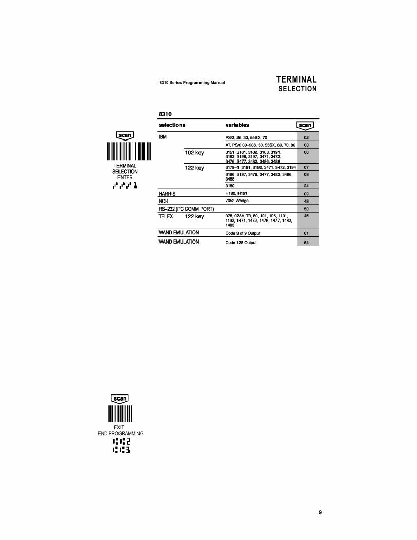
TERMINAL 8310 Series Information and Examples
SELECTION
TERMINAL SELECTION Use the bar codes on the following page to program the SCANTEAM 8310 to work with your terminal.
9
8310 Series Programming Manual TERMINAL
SELECTION
EXIT END PROGRAMMING
OUTPUT 8310 Ser ies In format ion and Examples
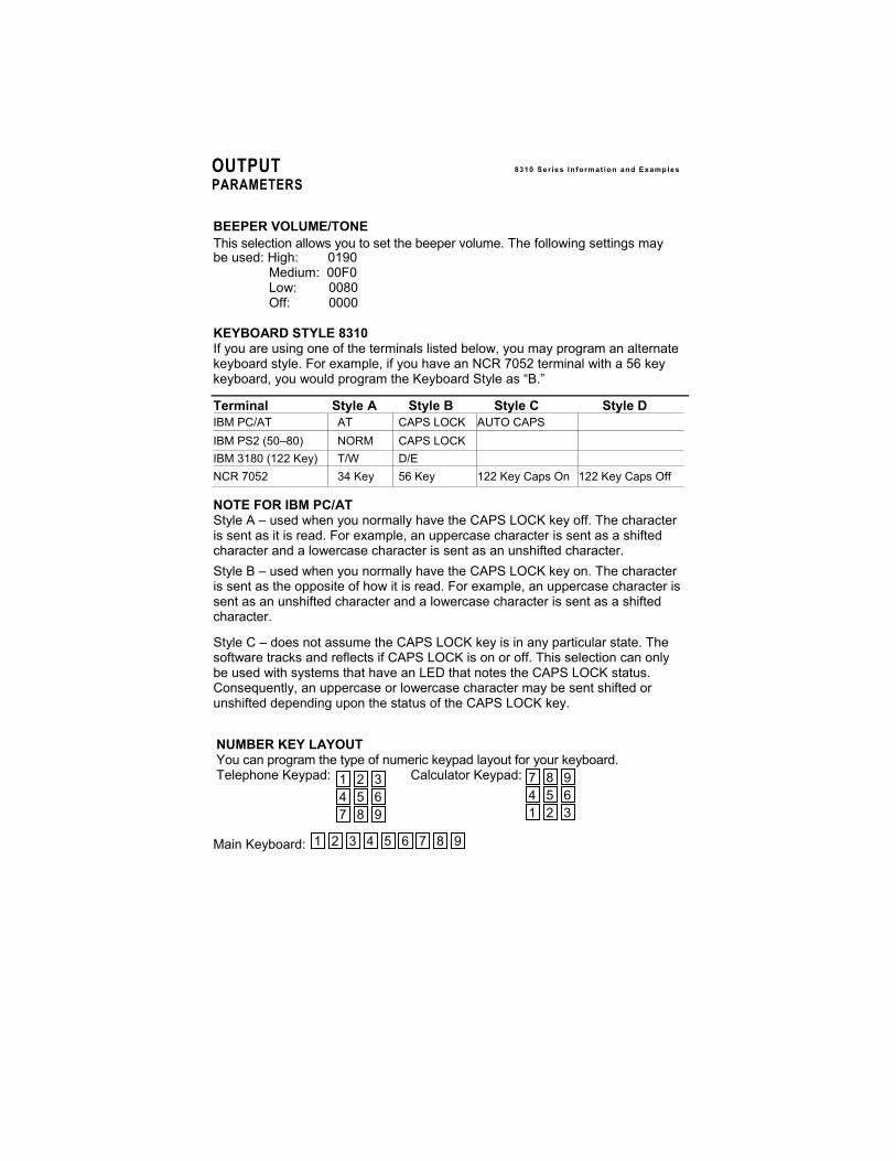
PARAMETERS BEEPER VOLUME/TONE This selection allows you to set the beeper volume. The following settings may be used: High: 0190
Medium: 00F0 Low: 0080 Off: 0000
KEYBOARD STYLE 8310 If you are using one of the terminals listed below, you may program an alternate keyboard style. For example, if you have an NCR 7052 terminal with a 56 key keyboard, you would program the Keyboard Style as “B.”
Terminal Style A Style B Style C Style D IBM PC/AT AT CAPS LOCK AUTO CAPS IBM PS2 (50–80) NORM CAPS LOCK IBM 3180 (122 Key) T/W D/E NCR 7052 34 Key 56 Key 122 Key Caps On 122 Key Caps Off NOTE FOR IBM PC/AT Style A – used when you normally have the CAPS LOCK key off. The character is sent as it is read. For example, an uppercase character is sent as a shifted character and a lowercase character is sent as an unshifted character. Style B – used when you normally have the CAPS LOCK key on. The character is sent as the opposite of how it is read. For example, an uppercase character is sent as an unshifted character and a lowercase character is sent as a shifted character.
Style C – does not assume the CAPS LOCK key is in any particular state. The software tracks and reflects if CAPS LOCK is on or off. This selection can only be used with systems that have an LED that notes the CAPS LOCK status. Consequently, an uppercase or lowercase character may be sent shifted or unshifted depending upon the status of the CAPS LOCK key.
NUMBER KEY LAYOUT You can program the type of numeric keypad layout for your keyboard. Telephone Keypad: Calculator Keypad: Main Keyboard:
1 2 3 4 5 6 7 8 9
1 2 34 5 67 8 9
7 8 94 5 61 2 3
8310 Series Programming Manual
11
OUTPUT PARAMETERS
* Designates default selections.
EXIT END PROGRAMMING
OUTPUT
PARAMETERS ENTER
KEYBOARD LAYOUT

12
OUTPUT 8310 Ser ies In format ion and Examples
PARAMETERS
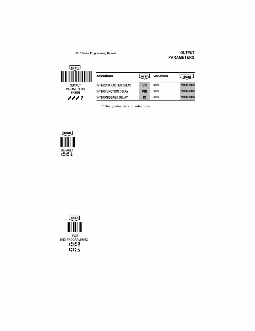
INTERCHARACTER, INTERFUNCTION, AND INTERMESSAGE DELAYS Some terminals drop information (characters) if data comes through too quickly. Intercharacter, interfunction, and intermessage delays slow the transmission of data, which increases data integrity. Intercharacter Delay:
An intercharacter delay is a delay of up to 9999 milliseconds (in multiples of 5) which is placed between the transmission of each character of scanned data.
Scanned Data
Intercharacter Delay
Interfunction Delay: An interfunction delay is a delay of up to 9999 milliseconds (in multiples of 5) which is placed between the transmission of each segment of the message string.
Prefix Scanned Data Suffix
Interfunction Delays
Intermessage Delay: An intermessage delay is a delay of up to 9999 milliseconds (in multiples of 5) which is placed between each data transmission.
1st Data Transmission Intermessage Delay
2nd Data Transmission
* Designates default selections.
EXIT END PROGRAMMING
8310 Series Programming Manual OUTPUTPARAMETERS
14
OUTPUT 8 3 1 0 S e r i e s I n fo r m at i on a nd E x a m p l e s
PARAMETERS continued
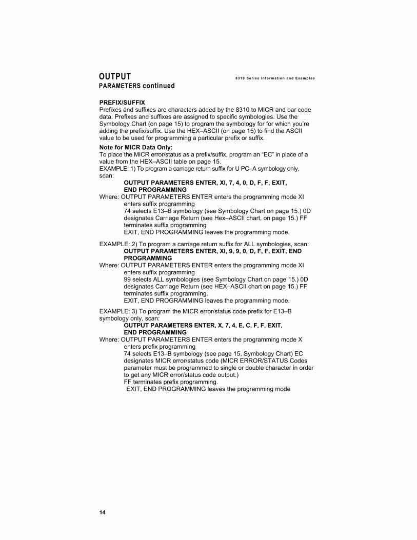
PREFIX/SUFFIX Prefixes and suffixes are characters added by the 8310 to MICR and bar code data. Prefixes and suffixes are assigned to specific symbologies. Use the Symbology Chart (on page 15) to program the symbology for for which you’re adding the prefix/suffix. Use the HEX–ASCII (on page 15) to find the ASCII value to be used for programming a particular prefix or suffix. Note for MICR Data Only: To place the MICR error/status as a prefix/suffix, program an “EC” in place of a value from the HEX–ASCII table on page 15. EXAMPLE: 1) To program a carriage return suffix for U PC–A symbology only, scan:
OUTPUT PARAMETERS ENTER, XI, 7, 4, 0, D, F, F, EXIT, END PROGRAMMING
Where: OUTPUT PARAMETERS ENTER enters the programming mode XI enters suffix programming 74 selects E13–B symbology (see Symbology Chart on page 15.) 0D designates Carriage Return (see Hex–ASCII chart, on page 15.) FF terminates suffix programming EXIT, END PROGRAMMING leaves the programming mode.
EXAMPLE: 2) To program a carriage return suffix for ALL symbologies, scan: OUTPUT PARAMETERS ENTER, XI, 9, 9, 0, D, F, F, EXIT, END PROGRAMMING
Where: OUTPUT PARAMETERS ENTER enters the programming mode XI enters suffix programming 99 selects ALL symbologies (see Symbology Chart on page 15.) 0D designates Carriage Return (see HEX–ASCII chart on page 15.) FF terminates suffix programming. EXIT, END PROGRAMMING leaves the programming mode.
EXAMPLE: 3) To program the MICR error/status code prefix for E13–B symbology only, scan:
OUTPUT PARAMETERS ENTER, X, 7, 4, E, C, F, F, EXIT, END PROGRAMMING
Where: OUTPUT PARAMETERS ENTER enters the programming mode X enters prefix programming 74 selects E13–B symbology (see page 15, Symbology Chart) EC designates MICR error/status code (MICR ERROR/STATUS Codes parameter must be programmed to single or double character in order to get any MICR error/status code output.) FF terminates prefix programming. EXIT, END PROGRAMMING leaves the programming mode
15
OUTPUT PARAMETERS continued
8310 Series Information and Examples
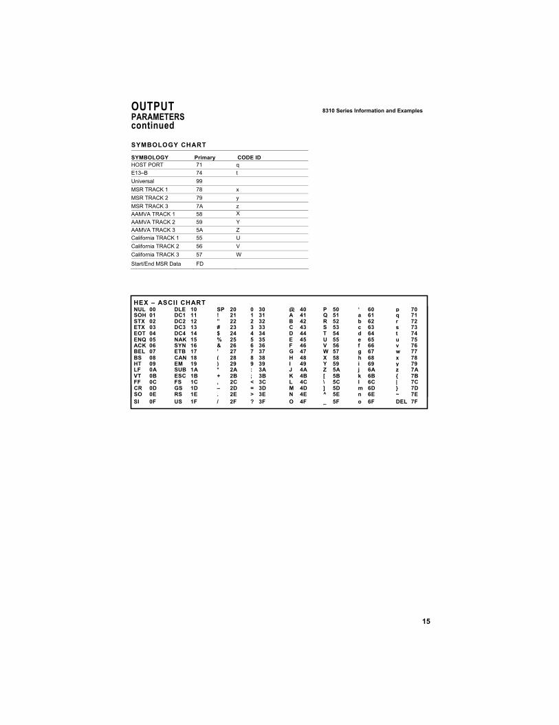
SYMBOLOGY CHART
SYMBOLOGY Primary CODE ID HOST PORT 71 q E13–B 74 t Universal 99 MSR TRACK 1 78 x MSR TRACK 2 79 y MSR TRACK 3 7A z AAMVA TRACK 1 58 X AAMVA TRACK 2 59 Y AAMVA TRACK 3 5A Z California TRACK 1 55 U California TRACK 2 56 V California TRACK 3 57 W
Start/End MSR Data FD
HEX – ASCII CHART NUL 00 DLE 10 SP 20 0 30 @ 40 P 50 ‘ 60 p 70 SOH 01 DC1 11 ! 21 1 31 A 41 Q 51 a 61 q 71 STX 02 DC2 12 ” 22 2 32 B 42 R 52 b 62 r 72 ETX 03 DC3 13 # 23 3 33 C 43 S 53 c 63 s 73 EOT 04 DC4 14 $ 24 4 34 D 44 T 54 d 64 t 74 ENQ 05 NAK 15 % 25 5 35 E 45 U 55 e 65 u 75 ACK 06 SYN 16 & 26 6 36 F 46 V 56 f 66 v 76 BEL 07 ETB 17 ’ 27 7 37 G 47 W 57 g 67 w 77 BS 08 CAN 18 ( 28 8 38 H 48 X 58 h 68 x 78 HT 09 EM 19 ) 29 9 39 I 49 Y 59 i 69 y 79 LF 0A SUB 1A * 2A : 3A J 4A Z 5A j 6A z 7A VT 0B ESC 1B + 2B ; 3B K 4B [ 5B k 6B { 7B FF 0C FS 1C , 2C < 3C L 4C \ 5C l 6C | 7C CR 0D GS 1D – 2D = 3D M 4D ] 5D m 6D } 7D SO 0E RS 1E . 2E > 3E N 4E ^ 5E n 6E ~ 7E SI 0F US 1F / 2F ? 3F O 4F _ 5F o 6F DEL 7F
16
OUTPUT 8 3 1 0 S e r i e s I n fo r m at i on a nd E x a m p l e s
PARAMETERS continued
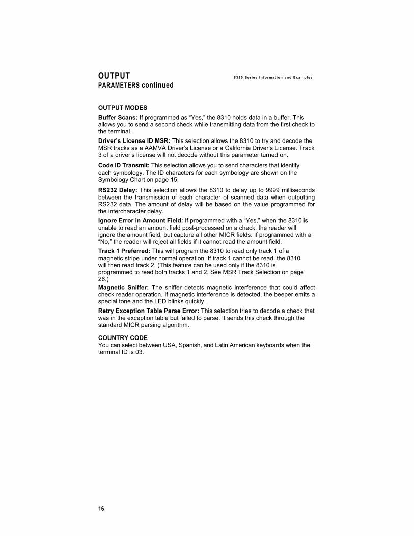
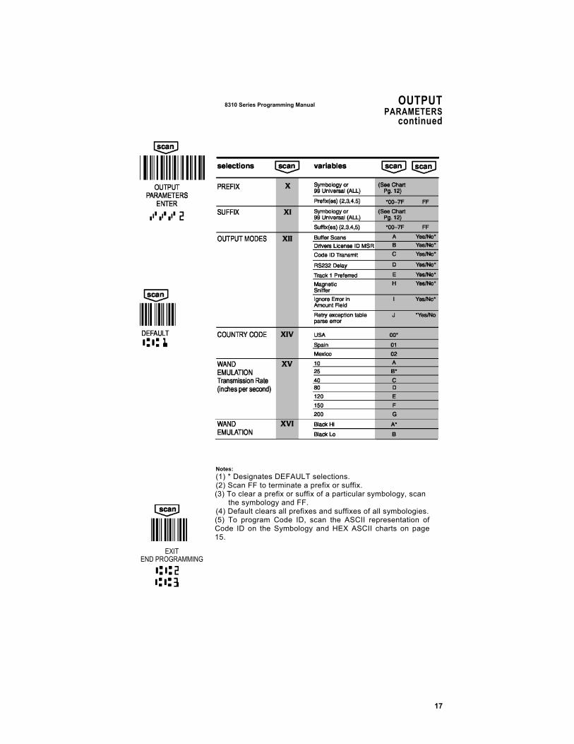
OUTPUT MODES Buffer Scans: If programmed as “Yes,” the 8310 holds data in a buffer. This allows you to send a second check while transmitting data from the first check to the terminal. Driver’s License ID MSR: This selection allows the 8310 to try and decode the MSR tracks as a AAMVA Driver’s License or a California Driver’s License. Track 3 of a driver’s license will not decode without this parameter turned on.
Code ID Transmit: This selection allows you to send characters that identify each symbology. The ID characters for each symbology are shown on the Symbology Chart on page 15.
RS232 Delay: This selection allows the 8310 to delay up to 9999 milliseconds between the transmission of each character of scanned data when outputting RS232 data. The amount of delay will be based on the value programmed for the intercharacter delay. Ignore Error in Amount Field: If programmed with a “Yes,” when the 8310 is unable to read an amount field post-processed on a check, the reader will ignore the amount field, but capture all other MICR fields. If programmed with a “No,” the reader will reject all fields if it cannot read the amount field. Track 1 Preferred: This will program the 8310 to read only track 1 of a magnetic stripe under normal operation. If track 1 cannot be read, the 8310 will then read track 2. (This feature can be used only if the 8310 is programmed to read both tracks 1 and 2. See MSR Track Selection on page 26.) Magnetic Sniffer: The sniffer detects magnetic interference that could affect check reader operation. If magnetic interference is detected, the beeper emits a special tone and the LED blinks quickly. Retry Exception Table Parse Error: This selection tries to decode a check that was in the exception table but failed to parse. It sends this check through the standard MICR parsing algorithm.
COUNTRY CODE You can select between USA, Spanish, and Latin American keyboards when the terminal ID is 03.
17
Notes: (1) * Designates DEFAULT selections. (2) Scan FF to terminate a prefix or suffix. (3) To clear a prefix or suffix of a particular symbology, scan
the symbology and FF. (4) Default clears all prefixes and suffixes of all symbologies. (5) To program Code ID, scan the ASCII representation of Code ID on the Symbology and HEX ASCII charts on page 15.
EXIT END PROGRAMMING
8310 Series Programming Manual OUTPUTPARAMETERS
continued
18
OUTPUT 8 3 1 0 S e r i e s I n fo r m at i on a nd E x a m p l e s
PARAMETERS continued
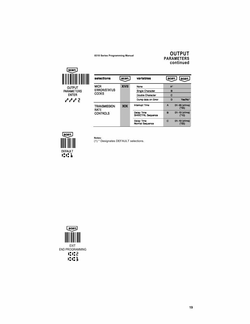
OUTPUT MODES MICR ERROR/STATUS CODES Use this option to output either a single or double character when there is a MICR Error/Status code to report. This selection also allows you to dump out any MICR data read on an error condition. Note: For Error Conditions When the MICR code on the check is in error and a triple beep occurs, the error code will only be output when this selection is set to single or double character. Note: For Status Conditions When the MICR code on the check is not in error but does have some other status condition to report (i.e., serial number in range 151 –300), this status code will only be output when this selection is set to single or double character AND the placement of the status code is set by either a prefix/suffix or data formatter command.
Note: For Placement and programmable MICR Error/Status Codes All MICR error/status code values can be programmed – see the MICR Data Formatter (page 31) to do this. To place the error/status code at the beginning or end of a MICR output string, use EC as the ASCII value when programming in a prefix/suffix. To place the error/status code in the middle of a MICR output string, use the EC Data Formatter Command.
TRANSMISSION RATE CONTROLS The Transmission Rate Controls can be used to speed up or slow down transmission when the check reader is interfacing keyboard wedge with a terminal ID 03. Use these selections to control how much delay there is between make/break sequences when wedging in keyboard data. Interrupt Time: Use this selection to control the amount of interrupt time between characters output.
Delay time Shift/CTRL Sequence: Use this selection to control the amount of delay time between make/break codes when outputting a shifted or CTRL key character.
Delay Time Normal Sequence: Use this selection to control the amount of delay time between make/break codes when outputting a normal data key character.
19
8310 Series Programming Manual OUTPUT
PARAMETERScontinued
Notes: (1) * Designates DEFAULT selections.
EXIT END PROGRAMMING
20
MAIN PORT CONFIGURATION 8310 Ser ies In format ion and Examples
Output
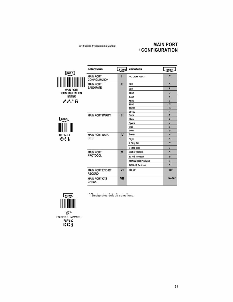
BAUD RATE The baud rate is programmable from 300 bits per second to 38,400 bits per second.
PARITY Parity provides a means of checking data bit patterns for validity. The parity should be programmed to match the parity of the terminal being used. If the parity is not set correctly, the resulting data may be incorrect.
DATA BITS The data bits selection must match the requirements of the terminal being used.
PROTOCOL A set of rules governing the exchange of data between communications devices. See Appendix A of the SCANTEAM 8300 Technical Manual for complete descriptions of supported protocols.
END OF RECORD Marks the end of an incoming data record from the Main Port. Use the HEX ASCII chart on page 15 to find the alpha–numeric codes used for programming a particular End of Record. The 8310 does not send End of Record characters to the terminal.
MAIN PORT CTS CHECK If programmed on (Yes), the 8310 will not transmit data until the CTS input is positive.
21
8310 Series Programming Manual MAIN PORTCONFIGURATION
EXIT END PROGRAMMING
* Designates default selections.

22
Notes: T h e s p a c e b e l o w m a y b e u s e d f o r n o t e s . . . .
23
8300 Ser ies In format ion and Examples DATA FORMATTERCOMMANDS
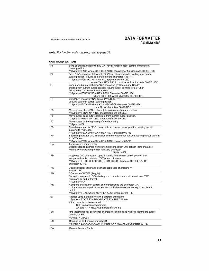
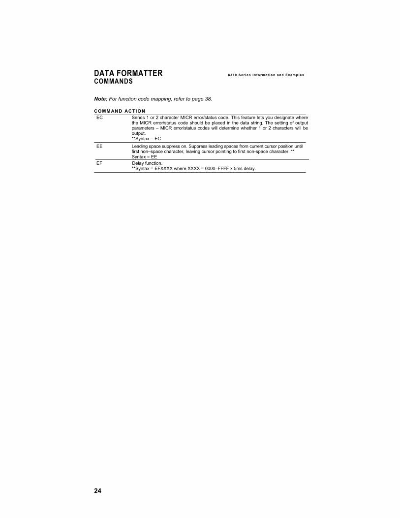
Note: For function code mapping, refer to page 38.
COMM AND ACTION F1 Send all characters followed by “XX” key or function code, starting from current
cursor position. ** Syntax = F1XX where XX = HEX ASCII character or function code 00–FE HEX F2 Send “NN” characters followed by “XX” key or function code, starting from current
cursor position, leaving cursor pointing to character “NN” + 1. ** Syntax = F2NNXX NN = No. of Characters 00–99 DEC.
where XX = HEX ASCII character or function code 00–FE HEX F3 Send up to but not including “SS” character, (** Search and Send**)
Starting from current cursor position, leaving cursor pointing to “SS” Char. followed by “XX” key or function code. ** Syntax = F3SSXX SS = HEX ASCII Character 00–FE HEX.
where XX = HEX ASCII character 00–FE HEX. F4 Send “XX” character “NN” times, (***INSERT***)
Leaving cursor in current cursor position. ** Syntax = F4XXNN where XX = HEX ASCII character 00–FE HEX
NN = No. of characters 00–99 DEC. F5 Move cursor ahead “NN” characters from current cursor position.
** Syntax = F5NN NN = No. of characters 00–99 DEC. F6 Move cursor back “NN” characters from current cursor position.
** Syntax = F6NN NN = No. of characters 00–99 DEC. F7 Move cursor to the beginning of the data string.
** Syntax = F7 F8 Searching ahead for “XX” character from current cursor position, leaving cursor
pointing to “XX” char. ** Syntax = F8XX where XX = HEX ASCII character 00-FE.
F9 Searching back for “XX” character from current cursor position, leaving cursor pointing to “XX” char. ** Syntax = F9XX where XX = HEX ASCII character 00-FE.
FA Leading zero suppress on Suppress leading zeroes from current cursor position until 1st non–zero character, leaving cursor pointing to first non-zero character.
** Syntax = FA FB Suppress “XX” character(s) up to 4 starting from current cursor position until
suppress disable command “FC” or end of format. ** Syntax = FBXXFB, FBXXXXFB, FBXXXXXXFB where XX = HEX ASCII character 00–FE.
FC Disable suppress filter and clear all suppressed characters. ** Syntax = FC
FD DCA mode ON/OFF (Toggle) Convert characters to DCA starting from current cursor position until next “FD” command or end of format. ** Syntax = FD
FE Compare character in current cursor position to the character “XX.” If characters are equal, increment cursor. If characters are not equal, no format match.
** Syntax = FEXX where XX = HEX ASCII Character 00 –FE E7 Replace up to 5 characters with 5 different characters.
**Syntax = E7XXRRXXRRXXRRXXRRXXRRE7 Where XX = character to be replaced
RR = replacement character XX and RR = HEX ACSII character 00–FE
E8 Find last (rightmost) occurrence of character and replace with RR, leaving the cursor pointing to RR.
**Syntax = E8XXRR E9 Replace up to 4 characters with RR. **Syntax = E9XXXXXXXXE9RR where XX = HEX ASCII Character 00–FE
EA Clear – Replace Table.
24
DATA FORMATTER 8 3 1 0 S e r i e s I n fo r m at i on a nd E x a m p l e s
Note: For function code mapping, refer to page 38.
COMM AND ACTION EC Sends 1 or 2 character MICR error/status code. This feature lets you designate where
the MICR error/status code should be placed in the data string. The setting of output parameters – MICR error/status codes will determine whether 1 or 2 characters will be output. **Syntax = EC
EE Leading space suppress on. Suppress leading spaces from current cursor position until first non–space character, leaving cursor pointing to first non-space character. ** Syntax = EE
EF Delay function. **Syntax = EFXXXX where XXXX = 0000–FFFF x 5ms delay.
COMMANDS
25
Notes:
(1) * Designates default selections. (2) For terminal selection, see page 9.
EXIT END PROGRAMMING
26
DATA FORMATTER 8310 Ser ies In format ion and Examples
COMMANDS continued
MSR DATA
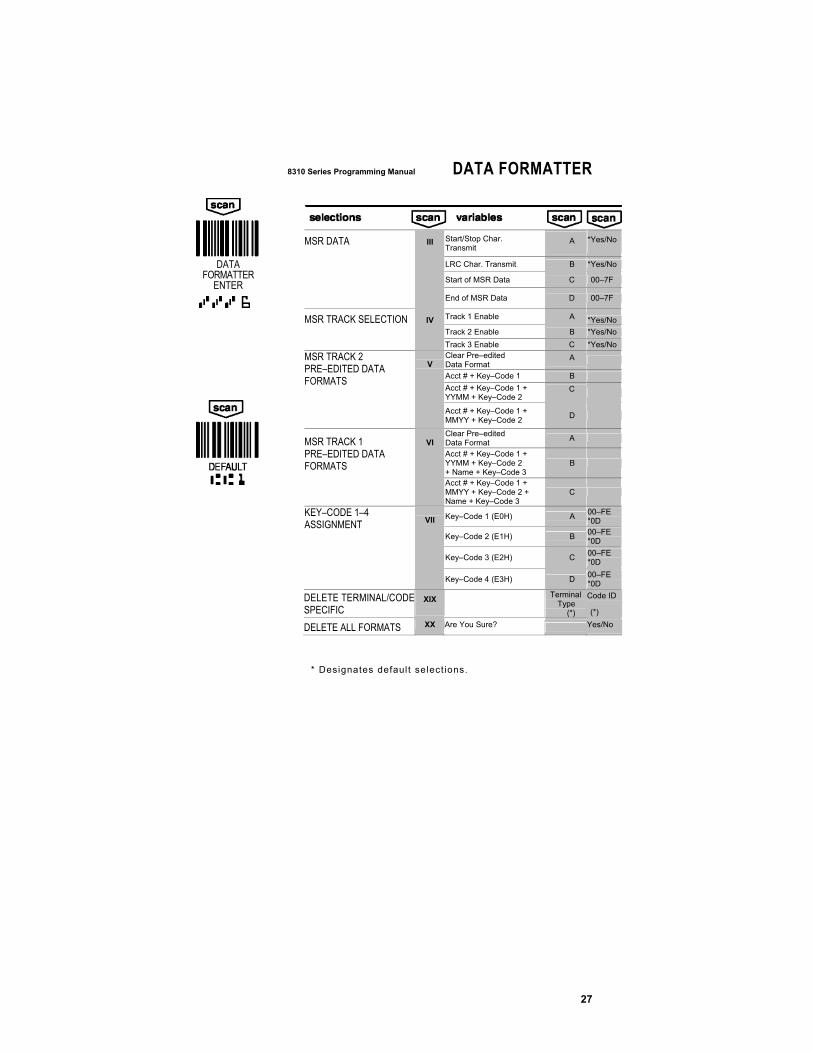
Start/Stop Character Transmit: Start/Stop characters identify the leading and trailing ends of the MSR data. You may either transmit, or not transmit Start/Stop characters.
LRC Character Transmit: This setting will enable or disable the transmission of a check digit for mag stripe data.
Start and End of MSR Data: Use these selections to program the start/stop characters you wish to use for MSR data. The start and end of MSR data is assigned a special symbology of “FD.”
MSR TRACK SELECTION Use this selection if you wish to enable or disable tracks 1, 2, and/or 3.
MSR PRE–EDITED DATA FORMATS These selections allow you to program the 8310 to transmit magnetic stripe data in a variety of formats which can include the account number, date, customer name, and any of the key code variables.
Note: Choosing a pre-edited MSR Data Format results in default selections for MSR Data (III). Therefore, Start/Stop Character Transmit and LRC Character Transmit will default to Yes.
KEY CODE ASSIGNMENT Key Codes are variables used to represent values in MSR data formats. Use this selection to assign values to the key codes. Note: Assignable delimiter or function codes al default to “0D.”
DELETE TERMINAL/CODE SPECIFIC
Use this selection to delete any formats which are specific to certain terminal and code ID combinations.
27
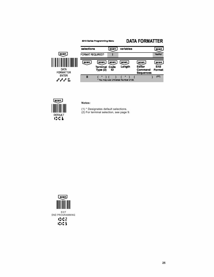
8310 Series Programming Manual DATA FORMATTER
* Designates default select ions.
DATA FORMATTER
ENTER
Start/Stop Char. Transmit
A *Yes/No
LRC Char. Transmit B *Yes/No
Start of MSR Data C 00–7F
MSR DATA III
End of MSR Data D 00–7F
Track 1 Enable A *Yes/No Track 2 Enable B *Yes/No
MSR TRACK SELECTION IV
Track 3 Enable C *Yes/No Clear Pre–edited Data Format
A
Acct # + Key–Code 1 B Acct # + Key–Code 1 + YYMM + Key–Code 2
C
MSR TRACK 2 PRE–EDITED DATA FORMATS
V
Acct # + Key–Code 1 + MMYY + Key–Code 2 D
Clear Pre–edited Data Format A
Acct # + Key–Code 1 + YYMM + Key–Code 2 + Name + Key–Code 3
B
MSR TRACK 1 PRE–EDITED DATA FORMATS
VI
Acct # + Key–Code 1 + MMYY + Key–Code 2 + Name + Key–Code 3
C
Key–Code 1 (E0H) A 00–FE *0D
Key–Code 2 (E1H) B 00–FE *0D
Key–Code 3 (E2H) C 00–FE *0D
KEY–CODE 1–4 ASSIGNMENT
VII
Key–Code 4 (E3H) D 00–FE *0D
DELETE TERMINAL/CODESPECIFIC
XIX Terminal
Type (*)
Code ID
(*)
DELETE ALL FORMATS XX Are You Sure? Yes/No

28
DATA FORMATTER continued 8300 Ser ies In format ion and Examples
Formatting MICR Output Example
Scenario: You have the following data on a check:
You have set the MICR Data Formatter output format to 02, which is <TRANSIT#>T<ACCOUNT#>A<CHECK SERIAL #>
The output you would like is: 021300381 <CR> 324036091 <CR> 4973
Solution: Go to page 25 (Data Formatter).
Step 1. Scan ENTER.
Step 2. Scan XX, then Yes to clear previous formats (this choice is from page 27).
Step 3. Scan II to enter Data Formatting parameters Scan 99 for universal terminal type Scan 74 for MICR symbology Scan 99 for variable length
Step 4. Scan your format parameters (scan each character in order): FB 20 64 FB F3 54 0D F5 01 F3 41 0D F5 01 F1 0D FF
Why: FB 20 64 FB
F3 54 0D
F5 01 F3 41 0D
F5 01 F1 0D
FF
FB suppresses characters, and you want to suppress spaces and dashes. Sends everything up to a T (hex 54), followed by a <CR> (hex 0D). Moves the cursor past the T. Sends everything up to an A (hex 41), followed by a <CR> (hex 0D). Moves the cursor past the A. Sends the rest of the code, followed by a <CR> (hex 0D). Termination character for end of format.
Step 5. Scan EXIT END PROGRAMMING.
29
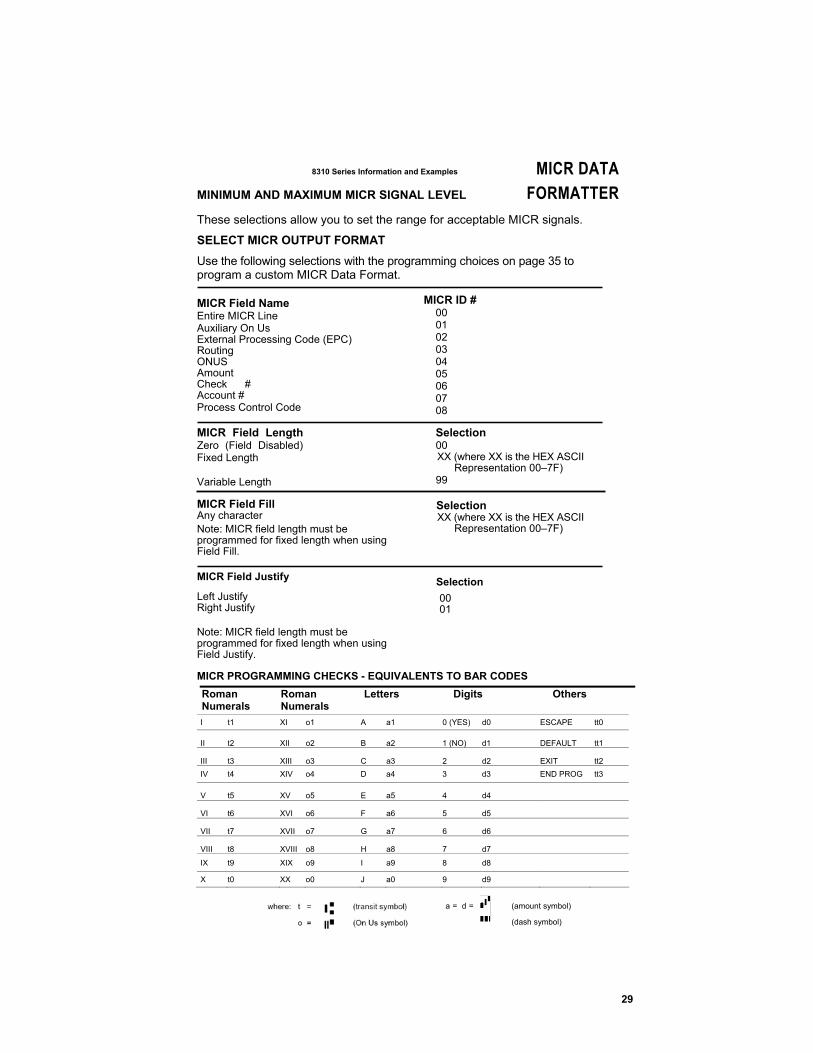
8310 Series Information and Examples MICR DATA MINIMUM AND MAXIMUM MICR SIGNAL LEVEL FORMATTER These selections allow you to set the range for acceptable MICR signals.
SELECT MICR OUTPUT FORMAT
Use the following selections with the programming choices on page 35 to program a custom MICR Data Format. MICR Field Name Entire MICR Line Auxiliary On Us External Processing Code (EPC) Routing ONUS Amount Check # Account # Process Control Code
MICR ID # 00 01 02 03 04 05 06 07 08
MICR Field Length Zero (Field Disabled) Fixed Length Variable Length
MICR Field Fill Any character Note: MICR field length must be programmed for fixed length when using Field Fill.
Selection 00 XX (where XX is the HEX ASCII
Representation 00–7F) 99 Selection XX (where XX is the HEX ASCII
Representation 00–7F)
MICR Field Justify
Left Justify Right Justify Note: MICR field length must be programmed for fixed length when using Field Justify.
Selection 00 01
MICR PROGRAMMING CHECKS - EQUIVALENTS TO BAR CODES Roman Roman Letters Digits Others Numerals Numerals I t1 XI o1 A a1 0 (YES) d0 ESCAPE tt0
II t2 XII o2 B a2 1 (NO) d1 DEFAULT tt1
III t3 XIII o3 C a3 2 d2 EXIT tt2 IV t4 XIV o4 D a4 3 d3 END PROG tt3
V t5 XV o5 E a5 4 d4
VI t6 XVI o6 F a6 5 d5
VII t7 XVII o7 G a7 6 d6
VIII t8 XVIII o8 H a8 7 d7 IX t9 XIX o9 I a9 8 d8 X t0 XX o0 J a0 9 d9
a = d =
(amount symbol)
(dash symbol)
30
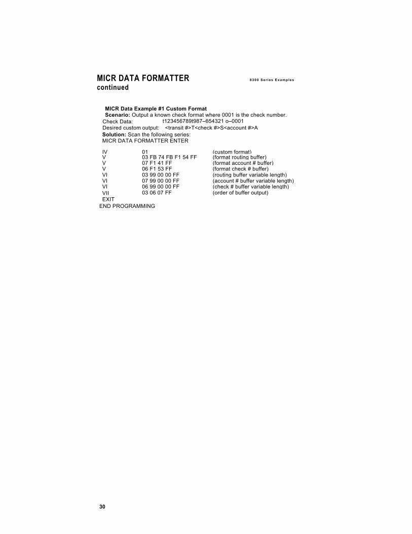
MICR DATA FORMATTER 8 3 0 0 S e r i e s E x a m p le s
continued
MICR Data Example #1 Custom Format Scenario: Output a known check format where 0001 is the check number.
t123456789t987–654321 o–0001Check Data: Desired custom output: <transit #>T<check #>S<account #>A Solution: Scan the following series: MICR DATA FORMATTER ENTER
IV 01 (custom format)V 03 FB 74 FB F1 54 FF (format routing buffer)V 07 F1 41 FF (format account # buffer)V 06 F1 53 FF (format check # buffer)VI 03 99 00 00 FF (routing buffer variable length)VI 07 99 00 00 FF (account # buffer variable length) VI 06 99 00 00 FF (check # buffer variable length)VII EXIT
03 06 07 FF (order of buffer output)
END PROGRAMMING
8310 Series Programming Manual MICR DATA FORMATTER
31
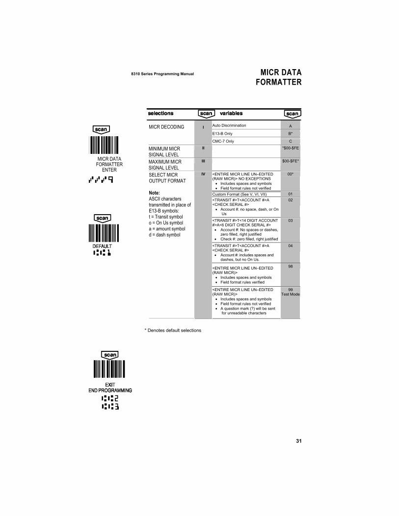
Auto Discrimination A
E13-B Only B* MICR DECODING I
CMC-7 Only C
MINIMUM MICR SIGNAL LEVEL
II
*$00-$FE
MAXIMUM MICR SIGNAL LEVEL
III
$00-$FE*
<ENTIRE MICR LINE UN–EDITED (RAW MICR)> NO EXCEPTIONS • Includes spaces and symbols • Field format rules not verified
00*
Custom Format (See V, VI, VII) 01 <TRANSIT #>T<ACCOUNT #>A <CHECK SERIAL #> • Account #: no space, dash, or On
Us
02
<TRANSIT #>T<14 DIGIT ACCOUNT #>A<6 DIGIT CHECK SERIAL #> • Account #: No spaces or dashes,
zero filled, right justified • Check #: zero filled, right justified
03
<TRANSIT #>T<ACCOUNT #>A <CHECK SERIAL #> • Account #: includes spaces and
dashes, but no On Us.
04
<ENTIRE MICR LINE UN–EDITED (RAW MICR)> • Includes spaces and symbols • Field format rules verified
98
SELECT MICR OUTPUT FORMAT Note: ASCII characters transmitted in place of E13-B symbols: t = Transit symbol o = On Us symbol a = amount symbol d = dash symbol
IV
<ENTIRE MICR LINE UN–EDITED (RAW MICR)> • Includes spaces and symbols • Field format rules not verified • A question mark (?) will be sent
for unreadable characters
99 Test Mode
* Denotes default selections
MICR DATA
FORMATTER ENTER
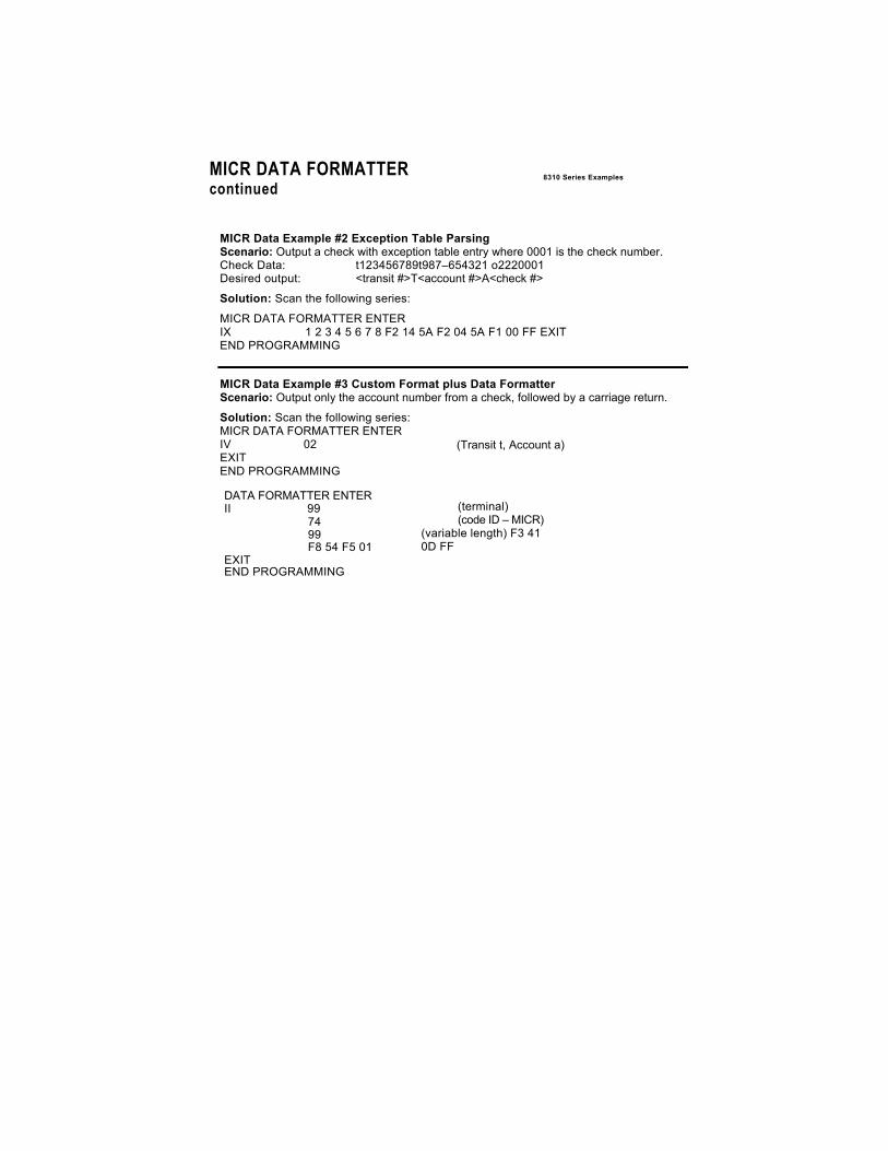
MICR DATA FORMATTER continued
8310 Series Examples
MICR Data Example #2 Exception Table Parsing Scenario: Output a check with exception table entry where 0001 is the check number. Check Data: t123456789t987–654321 o2220001 Desired output: <transit #>T<account #>A<check #>
Solution: Scan the following series:
MICR DATA FORMATTER ENTER IX 1 2 3 4 5 6 7 8 F2 14 5A F2 04 5A F1 00 FF EXIT END PROGRAMMING
MICR Data Example #3 Custom Format plus Data Formatter Scenario: Output only the account number from a check, followed by a carriage return.
Solution: Scan the following series: MICR DATA FORMATTER ENTER IV 02 EXIT END PROGRAMMING
(Transit t, Account a)
DATA FORMATTER ENTER II 99
74 99 F8 54 F5 01
EXIT END PROGRAMMING
(terminal) (code ID – MICR)
(variable length) F3 41 0D FF
33
8310 Series Programming Manual MICR DATA
FORMATTERcontinued
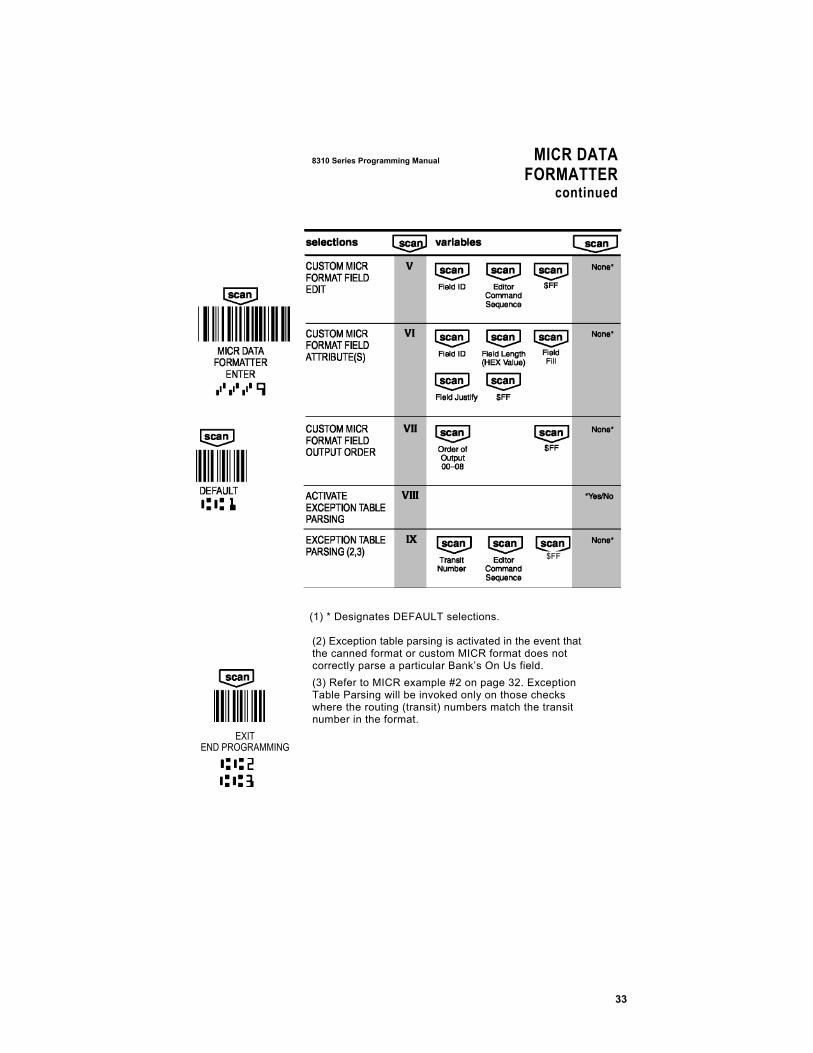
(1) * Designates DEFAULT selections.
(2) Exception table parsing is activated in the event that the canned format or custom MICR format does not correctly parse a particular Bank’s On Us field. (3) Refer to MICR example #2 on page 32. Exception Table Parsing will be invoked only on those checks where the routing (transit) numbers match the transit number in the format.
EXIT END PROGRAMMING
$FF
MICR DATA FORMATTER continued
8310 Series Examples
MICR ERROR/STATUS CODES Use the MICR ERROR/STATUS codes to control the values for all possible MICR error/status codes.
Each character must be from the HEX–ASCII table. For example, to program No MICR to a value of “XY”:
MICR DATA FORMATTER ENTER, XI, B, 58, 59, EXIT
When the OUTPUT PARAMETERS MICR ERROR/STATUS CODE is programmed to single character, only the second character for that particular error/status code will be output. In the above example, only “Y” will be output.
35
8310 Series Programming Manual MICR DATA
FORMATTERcontinued
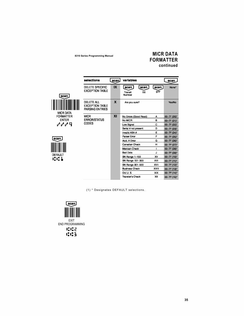
(1) * Des ignates DEFAULT se lect ions.
EXIT
END PROGRAMMING

STATUS CHECK 8310 Ser ies Programming M anual
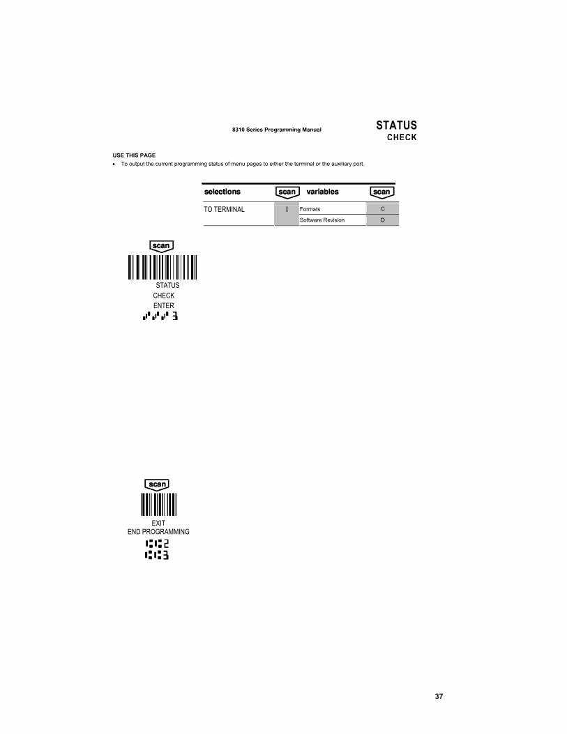
The Formats selection, choice C, lists the existing formats entered using the Data Formatter Programming page. Each format will be followed by a CR (carriage return) as listed.
37
8310 Series Programming Manual STATUS
CHECK USE THIS PAGE • To output the current programming status of menu pages to either the terminal or the auxiliary port.
EXIT
END PROGRAMMING
Formats C TO TERMINAL I
Software Revision D
STATUS
CHECK ENTER
38
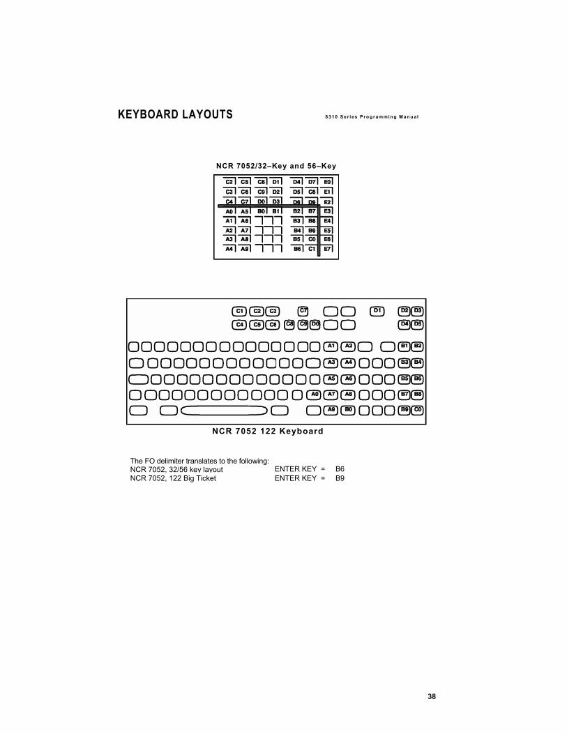
KEYBOARD LAYOUTS 8 3 1 0 S e r i e s P r o g r am m i ng M a n u a l
NCR 7052/32–Key and 56–Key
NCR 7052 122 Keyboard
The FO delimiter translates to the following: NCR 7052, 32/56 key layout ENTER KEY = B6 NCR 7052, 122 Big Ticket ENTER KEY = B9

39


41
8 3 1 0 S e r i e s P r o g r am m i ng M a n u a l USER’SNOTES
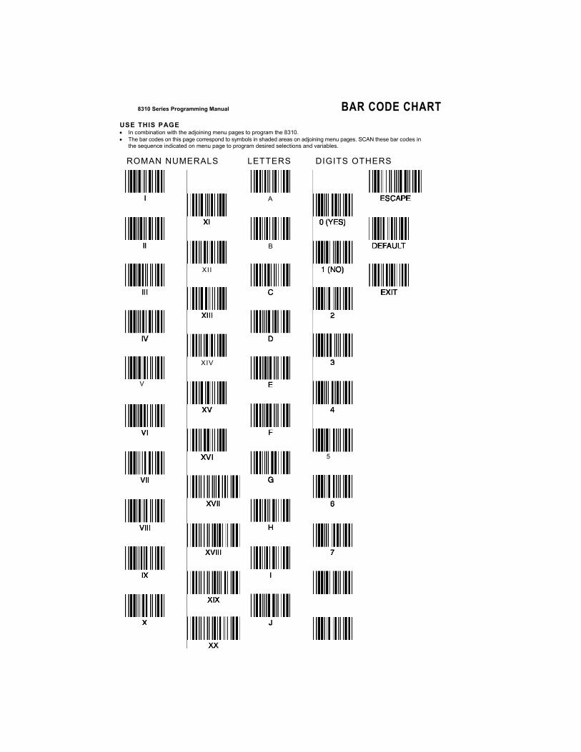
8310 Series Programming Manual BAR CODE CHART USE THIS PAGE • In combination with the adjoining menu pages to program the 8310. • The bar codes on this page correspond to symbols in shaded areas on adjoining menu pages. SCAN these bar codes in
the sequence indicated on menu page to program desired selections and variables.
ROMAN NUMERALS LETTERS DIGITS OTHERS
A
B
XII
XIV
5
V

43
8 3 1 0 S e r i e s P r o g r am m i ng M a n u a l USER’SNOTES

UIC Taipei Office: 1F, No.1, Lane 15, Chih Chiang St.,Tu Cheng City, Taipei Hsien, Taiwan, R.O.C.
UIC USA Office: 47709 Fremont Blvd., Fremont, CA 94538. USA. www.uicusa.com
8310/PM Rev D