a guide to machine safeguarding - summitholdings.com · from the principles and techniques of...
TRANSCRIPT

A Guide to
Machine Safeguarding
Bobby R. DavisSeries Editor
Division of Occupational Safety and HealthN.C. Department of Labor1101 Mail Service CenterRaleigh, NC 27699-1101
Cherie K. BerryCommissioner of Labor

N.C. Department of LaborOccupational Safety and Health Program
Cherie K. BerryCommissioner of Labor
OSHA State Plan Designee
Allen McNeelyDeputy Commissioner for Safety and Health
Kevin BeauregardAssistant Deputy Commissioner for Safety and Health
This edition of A Guide to Machine Safeguarding has been updated with material originally pre-pared in OSHA Publication 3067 (U.S. Department of Labor, Occupational Safety and HealthAdministration), Concepts and Techniques of Machine Safeguarding. OSHA Publication 3067 isreprinted in part within this guide with the permission of the U.S. Department of Labor for use bythe N.C. Department of Labor. This guide also contains information provided by U.S. Department ofHealth and Human Services, National Institute for Occupational Safety and Health. In addition, thispublication was also supplemented by a limited number of written explanations and illustrationsfrom The Principles and Techniques of Mechanical Guarding (Occupational Safety and HealthAdministration of the Arkansas Department of Labor); Injuries and Amputations Resulting FromWork With Mechanical Power Presses (NIOSH Publication No. 87-107); and the Health and SafetyGuide for the Tanning Industry (NIOSH Publication No. 77-101). Some changes have been made toreflect the North Carolina experience.
To obtain additional copies of this book, or if you have questions about N.C. occupational safety andhealth standards or rules, please contact:
N.C. Department of LaborBureau of Education, Training and Technical Assistance
1101 Mail Service CenterRaleigh, NC 27699-1101
Phone: (919) 807-2875 or 1-800-NC-LABOR (1-800-625-2267)
____________________
Additional sources of information are listed on the inside back cover of this book.
____________________
The projected cost of the OSHNC program for federal fiscal year 2000–2001 is $14,152,395. Federal funding provides approximately 30 percent($4,528,766) of this total.
Printed 08/01, 1M
ContentsPart Page
Foreword . . . . . . . . . . . . . . . . . . . . . . . . . . . . . . . . . . . . . . . . . . .1iiv
Introduction . . . . . . . . . . . . . . . . . . . . . . . . . . . . . . . . . . . . . . . .1iiv
1 Basics of Machine Safeguarding . . . . . . . . . . . . . . . . . . . . . . .1ii1
2 Methods of Machine Safeguarding . . . . . . . . . . . . . . . . . . . . . . ii10
3 Guard Construction (and special notice of abrasive wheel guards andof power press guards) . . . . . . . . . . . . . . . . . . . . . . . . . . . . . ii52
4 Machinery Maintenance and Repair . . . . . . . . . . . . . . . . . . . . . ii57
5 Cooperation and Assistance . . . . . . . . . . . . . . . . . . . . . . . . . . ii61
Checklist . . . . . . . . . . . . . . . . . . . . . . . . . . . . . . . . . . . . ii62
iii
ForewordUnguarded machinery claims far too many limbs and lives from North Carolina’s working people. Such
tragedies can be avoided by better training for machine operators, and most importantly, by makingmachines in the workplace safer.
This guide examines dozens of possible ways to safeguard machinery. There is even a machine safetychecklist in the back of the book so the reader can see how his or her own workplace rates. A Guide toMachine Safeguarding also explains many issues related to making workplaces safer.
In North Carolina, state inspectors enforce the federal Occupational Safety and Health Act (OSHA)through a state plan approved by the U.S. Department of Labor. The N.C. Department of Labor’s Divisionof Occupational Safety and Health is charged with this mission. OSHNC offers many educational pro-grams to the public and produces publications, including this guide, to help inform people about theirrights and responsibilities regarding occupational safety and health.
When looking through this guide, please remember that OSHNC’s mission is greater than just toenforce regulations. An equally important goal is to help citizens find ways to create safe workplaces.Everyone profits when managers and employees work together for safety. This booklet, like the other edu-cational materials produced by the N.C. Department of Labor, can help.
Reading and understanding A Guide to Machine Safeguarding will help you form a sound occupationalsafety and health policy where you work.
Cherie K. BerryCommissioner of Labor
iv
IntroductionThis industry guide has been prepared as an aid to employers, employees, machine manufacturers,
machine guard designers and fabricators, and all others with an interest in protecting workers againstthe hazards of moving machine parts. It identifies the major mechanical motions and actions, and thegeneral principles of safeguarding them.
The basic types of mechanical action or motion that must be guarded are found in many machines inmany industries. Current applications of each technique are shown in accompanying illustrations of spe-cific operations and machines. The concepts described here may, with due care, be transferred to differentmachines with similar motions. Any moving part creates a hazard and guarding eliminates or controlsthe hazard. However, this guide does not attempt to discuss all possible approaches to machine safe-guarding.
For particular areas of concern, the reader should consult additional sources of information. Two topicsthat demand further research on the reader’s part are safeguarding practices and procedures during themaintenance of machinery and safeguards for robotic machinery.
• Injuries from machinery undergoing maintenance are numerous. Preventing such injuries fromoccurring during machine maintenance requires further study on the reader’s part.
• Although robotic machinery is relatively new, its use is expanding at a fast pace. Therefore, safe-guarding for robotic machinery demands additional research efforts.
In machine safeguarding, as in other regulated areas of the American workplace, to a certain extent,Occupational Safety and Health Administration standards govern function and practice. This text is nota substitute for OSHA standards. For OSHA standards regarding machine guards, the reader shouldrefer to North Carolina OSHA Standards for General Industry (Subpart O—Machinery and MachineGuarding).
This is a manual of basic technical information and workable ideas that the employer may use as aguide to voluntary compliance. By understanding the basic techniques for guarding simple machinery,one is better able to cope with the problems involving more complex machinery. This guide offers anoverview of the machine safeguarding problem in its industrial setting, an assortment of solutions in pop-ular use, and a challenge to all whose work involves machines.
Many readers of this guide already have the judgment, knowledge and skill to develop effectiveanswers to problems yet unsolved. Innovators are encouraged to use this guide to help them find newways to eliminate hazards by properly guarding the machines used by North Carolina employees.
Though this guide is intended to be consistent with OSHA standards, if an area is considered by thereader to be inconsistent, the OSHA standard should be followed.
v
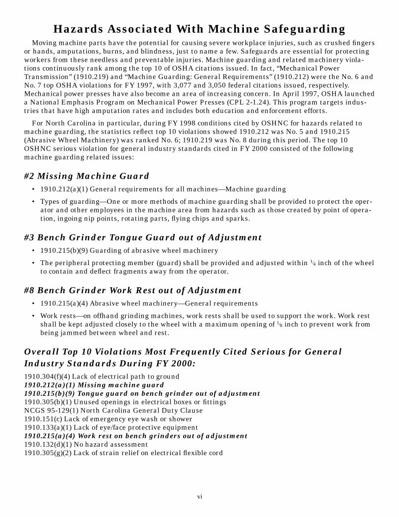
Hazards Associated With Machine SafeguardingMoving machine parts have the potential for causing severe workplace injuries, such as crushed fingers
or hands, amputations, burns, and blindness, just to name a few. Safeguards are essential for protectingworkers from these needless and preventable injuries. Machine guarding and related machinery viola-tions continuously rank among the top 10 of OSHA citations issued. In fact, “Mechanical PowerTransmission” (1910.219) and “Machine Guarding: General Requirements” (1910.212) were the No. 6 andNo. 7 top OSHA violations for FY 1997, with 3,077 and 3,050 federal citations issued, respectively.Mechanical power presses have also become an area of increasing concern. In April 1997, OSHA launcheda National Emphasis Program on Mechanical Power Presses (CPL 2-1.24). This program targets indus-tries that have high amputation rates and includes both education and enforcement efforts.
For North Carolina in particular, during FY 1998 conditions cited by OSHNC for hazards related tomachine guarding, the statistics reflect top 10 violations showed 1910.212 was No. 5 and 1910.215(Abrasive Wheel Machinery) was ranked No. 6; 1910.219 was No. 8 during this period. The top 10OSHNC serious violation for general industry standards cited in FY 2000 consisted of the followingmachine guarding related issues:
#2 Missing Machine Guard• 1910.212(a)(1) General requirements for all machines—Machine guarding
• Types of guarding—One or more methods of machine guarding shall be provided to protect the oper-ator and other employees in the machine area from hazards such as those created by point of opera-tion, ingoing nip points, rotating parts, flying chips and sparks.
#3 Bench Grinder Tongue Guard out of Adjustment• 1910.215(b)(9) Guarding of abrasive wheel machinery
• The peripheral protecting member (guard) shall be provided and adjusted within 1/4 inch of the wheelto contain and deflect fragments away from the operator.
#8 Bench Grinder Work Rest out of Adjustment• 1910.215(a)(4) Abrasive wheel machinery—General requirements
• Work rests—on offhand grinding machines, work rests shall be used to support the work. Work restshall be kept adjusted closely to the wheel with a maximum opening of 1/8 inch to prevent work frombeing jammed between wheel and rest.
Overall Top 10 Violations Most Frequently Cited Serious for GeneralIndustry Standards During FY 2000:1910.304(f)(4) Lack of electrical path to ground1910.212(a)(1) Missing machine guard1910.215(b)(9) Tongue guard on bench grinder out of adjustment1910.305(b)(1) Unused openings in electrical boxes or fittingsNCGS 95-129(1) North Carolina General Duty Clause1910.151(c) Lack of emergency eye wash or shower 1910.133(a)(1) Lack of eye/face protective equipment1910.215(a)(4) Work rest on bench grinders out of adjustment1910.132(d)(1) No hazard assessment 1910.305(g)(2) Lack of strain relief on electrical flexible cord
vi

Deaths and Injuries in North Carolina Associated WithMachine Safeguarding Problems
The absence of proper safeguarding of machinery is a major cause of injuries to employees in NorthCarolina. The following list provides examples of such injuries.
• James T. Briggs was killed by the unguarded tenter frame he operated. Mr. Briggs was a doffer for atextile company in Greensboro, N.C. He was fatally injured when he leaned into an unguarded area ofthe machine to untangle a piece of cloth from the rollers. The transfer unit sides of the machine closedon Mr. Briggs’ head, causing his death.
• M.C. Tate’s middle and index fingers were amputated from his right hand after he was injured by anunguarded 60 ton punch press. Mr. Tate was employed as a punch-press operator by a manufacturerin Burlington, N.C.
• Michelle Robbins’ left arm was severed at her elbow by the unguarded meat-grinding machine shewas operating. Not only was the chute of the meat grinder unguarded, but there was no push stickavailable to distance her hands from the point of operation. The auger of the grinder grabbed Ms.Robbins’ fingers and continuously pulled her hand and arm into the machine. Ms. Robbins was 19years old. She was an employee of a grocery store in Fuquay-Varina, N.C.
• Two of the fingers on Andrew Houser’s left hand were removed after he was injured by a mechanicalpower press. Mr. Houser, then 19, was employed by a metal fabricating company in Wilmington, N.C.Mr. Houser’s operating procedure was to place pieces of metal into the point of operation, then causethe ram of the machine to descend, by depressing a push-button trip that could be activated with onlyone hand. The press cycled as Mr. Houser removed a piece of metal from the point of operation.
• Emergency surgery was required to remove a piece of wood from Glen Beverly’s stomach. The woodwas driven into his stomach after splintering from lumber running through the edger that Mr.Beverly operated. Mr. Beverly was employed in a sawmill in Mount Airy, N.C.
• Sylvia Coxum’s left index finger was severed by a mechanical power press. Ms. Coxum was not ade-quately trained to make certain that the point of operation was guarded prior to operating the press.The injury occurred when she used her hand to remove a part from the die of the unguarded press.Ms. Coxum was 29 years old when she was injured on her job. She worked for a manufacturer inDunn, N.C.
• James R. Smith, 49, lost a finger to the unguarded cigarette-making machine that he operated. Mr.Smith was employed by a tobacco company in Winston-Salem, N.C.
• Stanford C. Joyner had two fingers amputated after being injured by a mechanical power press. Mr.Joyner was employed in a factory as a set-up man. The injury occurred as Mr. Joyner was checkingthe parts produced by the machine following his set-up of the press die.
vii
1Basics of Machine Safeguarding
Crushed hands and arms, severed fingers, blindness—the list of possible machinery-related injuries isas long as it is horrifying. There seem to be as many hazards created by moving machine parts as thereare types of machines. Safeguards are essential for protecting workers from needless and preventableinjuries.
A good rule to remember is: Any machine part, function or process that may cause injury must be safe-guarded. Where the operation of a machine or accidental contact with it can injure the operator or othersin the vicinity, the hazard must be either eliminated or controlled.
This guide describes the various hazards of mechanical motion and action and presents some tech-niques for protecting workers from these hazards. General information is covered in this chapter: wheremechanical hazards occur, the kinds of motions that need safeguarding, the requirements for effectivesafeguards, a brief discussion of nonmechanical hazards, and some other considerations.
Where Mechanical Hazards OccurDangerous moving parts in these three basic areas need safeguarding:
The Point of Operation
The point of operation is that point where work is performed on the material, such as cutting, shaping,boring or forming of stock.
Power Transmission Apparatus
Power transmission apparatus are all components of the mechanical system that transmit energy tothe part of the machine performing the work. These components include flywheels, pulleys, belts, con-necting rods, couplings, cams, spindles, chains, cranks and gears.
Other Moving Parts
Other moving parts include all parts of the machine that move while the machine is working. Thesecan be reciprocating, rotating and transverse moving parts, as well as feed mechanisms and auxiliaryparts of the machine.
Hazardous Mechanical Motions and ActionsA wide variety of mechanical motions and actions may present hazards to the worker. These can
include the movement of rotating members, reciprocating arms, moving belts, meshing gears, cuttingteeth, and any parts that impact or shear. These different types of hazardous mechanical motions andactions are basic to nearly all machines, and recognizing them is the first step toward protecting workersfrom the danger they present.
The basic types of hazardous mechanical motions and actions are:(Motions) (Actions)• rotating (including in-running nip points) • cutting• reciprocating • punching• transverse • shearing
• bending
We will briefly examine each of these basic types, in turn.
1
Motions
Rotating Motion
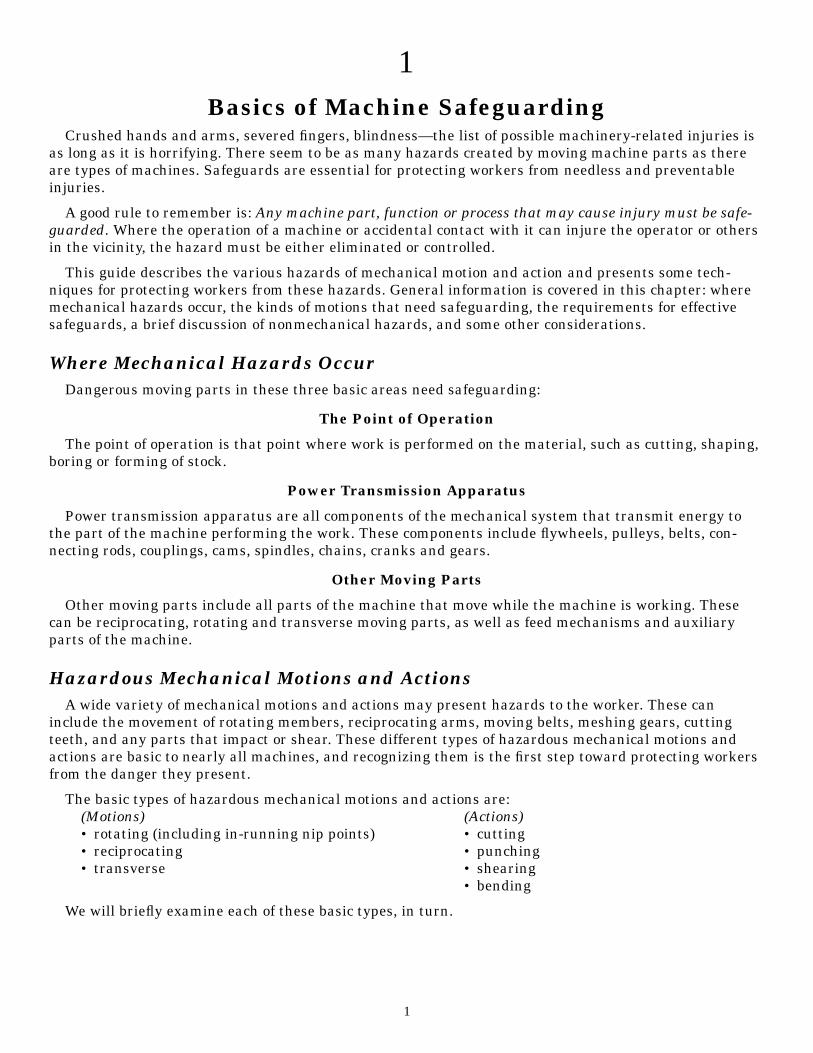
Rotating motion can be dangerous; even smooth, slowly rotating shafts can grip clothing, and throughmere skin contact, force an arm or hand into a dangerous position. Injuries due to contact with rotatingparts can be severe.
Collars, couplings, cams, clutches, flywheels, shaft ends, spindles, and horizontal or vertical shaftingare some examples of common rotating mechanisms that may be hazardous. The danger increases whenbolts, nicks, abrasions, and projecting keys or set screws are exposed on rotating parts. See figure 1.
Figure 1
Examples of Typical Rotating Mechanisms
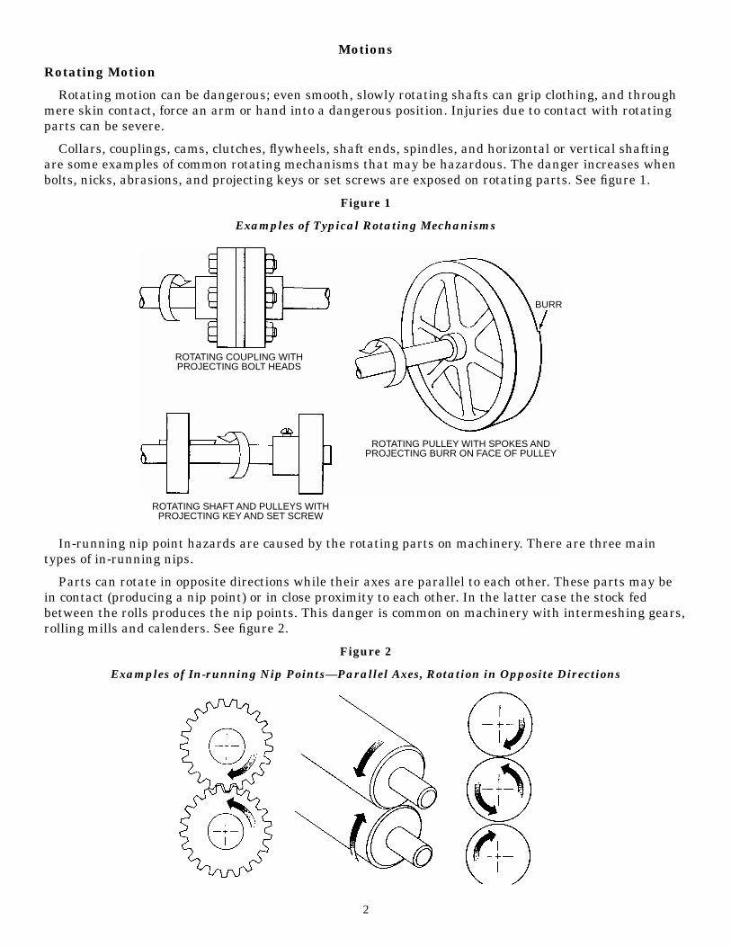
In-running nip point hazards are caused by the rotating parts on machinery. There are three maintypes of in-running nips.
Parts can rotate in opposite directions while their axes are parallel to each other. These parts may bein contact (producing a nip point) or in close proximity to each other. In the latter case the stock fedbetween the rolls produces the nip points. This danger is common on machinery with intermeshing gears,rolling mills and calenders. See figure 2.
Figure 2
Examples of In-running Nip Points—Parallel Axes, Rotation in Opposite Directions
2
ROTATING COUPLING WITHPROJECTING BOLT HEADS
ROTATING SHAFT AND PULLEYS WITHPROJECTING KEY AND SET SCREW
ROTATING PULLEY WITH SPOKES ANDPROJECTING BURR ON FACE OF PULLEY
BURR
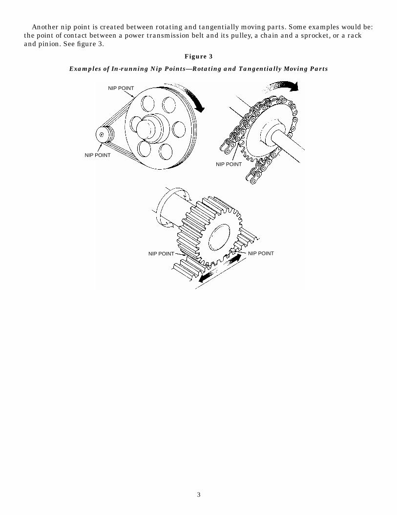
Another nip point is created between rotating and tangentially moving parts. Some examples would be:the point of contact between a power transmission belt and its pulley, a chain and a sprocket, or a rackand pinion. See figure 3.
Figure 3
Examples of In-running Nip Points—Rotating and Tangentially Moving Parts
3
NIP POINT
NIP POINT
NIP POINT NIP POINT
NIP POINT
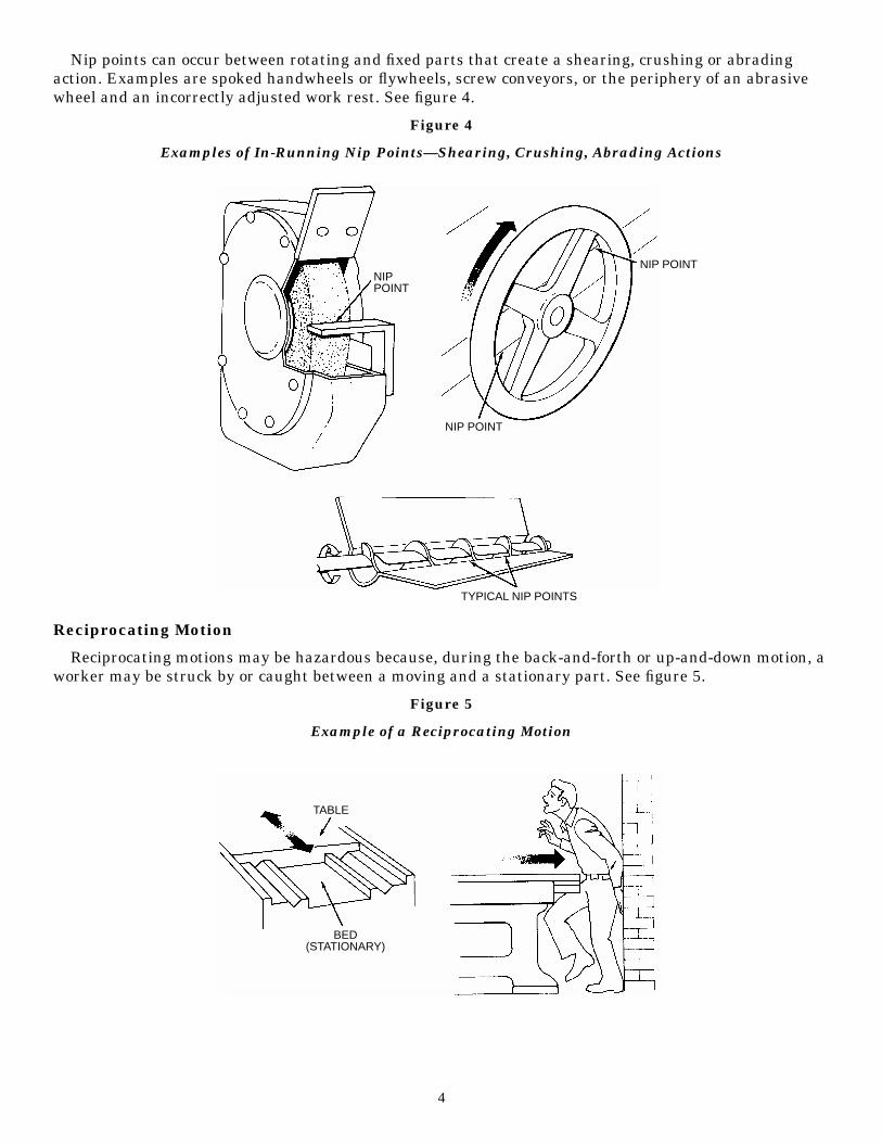
Nip points can occur between rotating and fixed parts that create a shearing, crushing or abradingaction. Examples are spoked handwheels or flywheels, screw conveyors, or the periphery of an abrasivewheel and an incorrectly adjusted work rest. See figure 4.
Figure 4
Examples of In-Running Nip Points—Shearing, Crushing, Abrading Actions
Reciprocating Motion
Reciprocating motions may be hazardous because, during the back-and-forth or up-and-down motion, aworker may be struck by or caught between a moving and a stationary part. See figure 5.
Figure 5
Example of a Reciprocating Motion
4
NIPPOINT
NIP POINT
NIP POINT
TYPICAL NIP POINTS
TABLE
BED(STATIONARY)
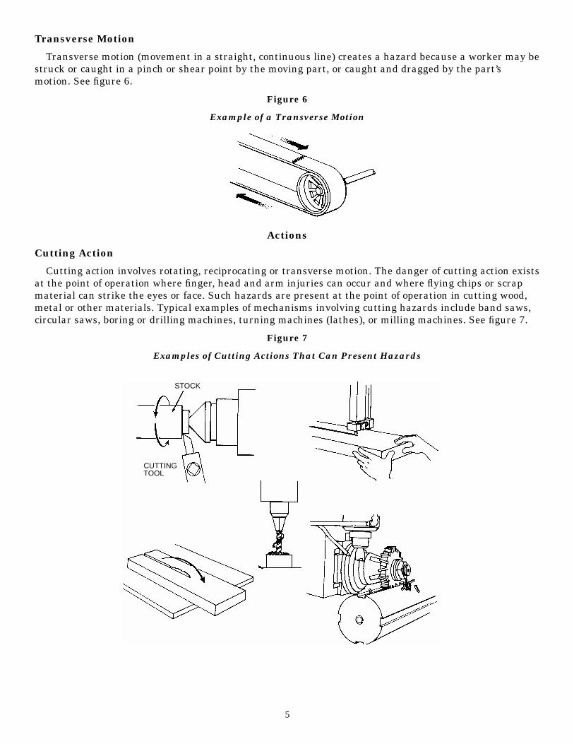
Transverse Motion
Transverse motion (movement in a straight, continuous line) creates a hazard because a worker may bestruck or caught in a pinch or shear point by the moving part, or caught and dragged by the part’smotion. See figure 6.
Figure 6
Example of a Transverse Motion
Actions
Cutting Action
Cutting action involves rotating, reciprocating or transverse motion. The danger of cutting action existsat the point of operation where finger, head and arm injuries can occur and where flying chips or scrapmaterial can strike the eyes or face. Such hazards are present at the point of operation in cutting wood,metal or other materials. Typical examples of mechanisms involving cutting hazards include band saws,circular saws, boring or drilling machines, turning machines (lathes), or milling machines. See figure 7.
Figure 7
Examples of Cutting Actions That Can Present Hazards
5
STOCK
CUTTINGTOOL
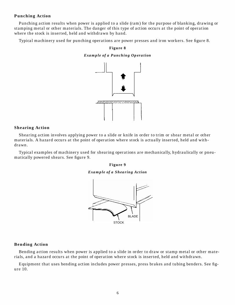
Punching Action
Punching action results when power is applied to a slide (ram) for the purpose of blanking, drawing orstamping metal or other materials. The danger of this type of action occurs at the point of operationwhere the stock is inserted, held and withdrawn by hand.
Typical machinery used for punching operations are power presses and iron workers. See figure 8.
Figure 8
Example of a Punching Operation
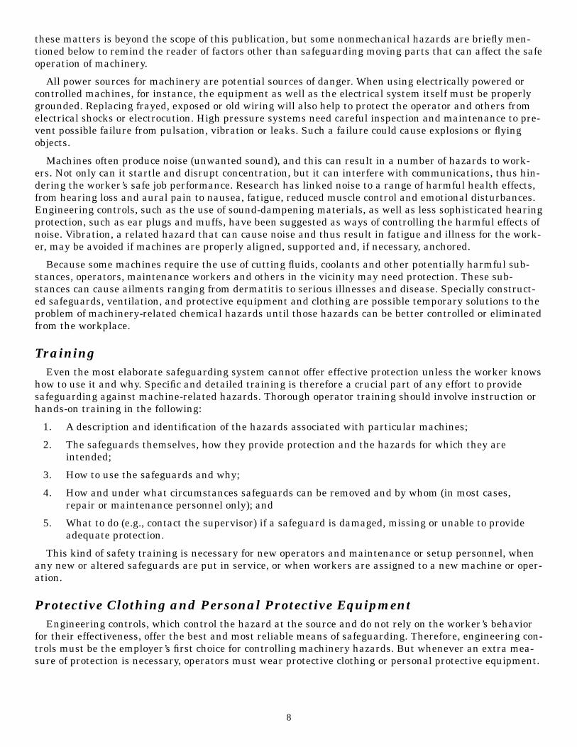
Shearing Action
Shearing action involves applying power to a slide or knife in order to trim or shear metal or othermaterials. A hazard occurs at the point of operation where stock is actually inserted, held and with-drawn.
Typical examples of machinery used for shearing operations are mechanically, hydraulically or pneu-matically powered shears. See figure 9.
Figure 9
Example of a Shearing Action
Bending Action
Bending action results when power is applied to a slide in order to draw or stamp metal or other mate-rials, and a hazard occurs at the point of operation where stock is inserted, held and withdrawn.
Equipment that uses bending action includes power presses, press brakes and tubing benders. See fig-ure 10.
6
STOCK
BLADE

Figure 10
Example of a Bending Operation
Requirements for SafeguardsWhat must a safeguard do to protect workers against mechanical hazards? Safeguards must meet
these minimum general requirements:
Prevent Contact
The safeguard must prevent hands, arms or any other part of a worker’s body from making contactwith dangerous moving parts. A good safeguard system eliminates the possibility of the operator oranother worker placing his or her hands near hazardous moving parts.
Be Secured to the Machine
Workers should not be able to remove or tamper easily with the safeguard, because a safeguard thatcan easily be made ineffective is no safeguard at all. Guards and safety devices should be made of durablematerial that will withstand the conditions of normal use. They must be firmly secured to the machine.
Protect From Falling Objects
The safeguard should ensure that no objects can fall into moving parts. A small tool that is droppedinto a cycling machine could easily become a projectile that could strike and injure someone.
Not Create New Hazards
A safeguard defeats its own purpose if it creates a hazard of its own, such as a shear point, a jaggededge or an unfinished surface that can cause a laceration. The edges of guards, for instance, should berolled or bolted in such a way that they eliminate sharp edges.
Not Interfere With Job Performance
Any safeguard that impedes a worker from performing the job quickly and comfortably might soon beoverridden or disregarded. Proper safeguarding can actually enhance efficiency since it can relieve theworker’s apprehensions about injury.
Allow for Safe Lubrication of the Machine
If possible, one should be able to lubricate the machine without removing the safeguards. Locating oilreservoirs outside the guard, with a line leading to the lubrication point, will reduce the need for theoperator or maintenance worker to enter the hazardous area.
Nonmechanical HazardsWhile this manual concentrates attention on concepts and techniques for safeguarding mechanical
motion, machines obviously present a variety of other hazards that cannot be ignored. Full discussion of
7
PUNCH
STOCK
DIE
these matters is beyond the scope of this publication, but some nonmechanical hazards are briefly men-tioned below to remind the reader of factors other than safeguarding moving parts that can affect the safeoperation of machinery.
All power sources for machinery are potential sources of danger. When using electrically powered orcontrolled machines, for instance, the equipment as well as the electrical system itself must be properlygrounded. Replacing frayed, exposed or old wiring will also help to protect the operator and others fromelectrical shocks or electrocution. High pressure systems need careful inspection and maintenance to pre-vent possible failure from pulsation, vibration or leaks. Such a failure could cause explosions or flyingobjects.
Machines often produce noise (unwanted sound), and this can result in a number of hazards to work-ers. Not only can it startle and disrupt concentration, but it can interfere with communications, thus hin-dering the worker’s safe job performance. Research has linked noise to a range of harmful health effects,from hearing loss and aural pain to nausea, fatigue, reduced muscle control and emotional disturbances.Engineering controls, such as the use of sound-dampening materials, as well as less sophisticated hearingprotection, such as ear plugs and muffs, have been suggested as ways of controlling the harmful effects ofnoise. Vibration, a related hazard that can cause noise and thus result in fatigue and illness for the work-er, may be avoided if machines are properly aligned, supported and, if necessary, anchored.
Because some machines require the use of cutting fluids, coolants and other potentially harmful sub-stances, operators, maintenance workers and others in the vicinity may need protection. These sub-stances can cause ailments ranging from dermatitis to serious illnesses and disease. Specially construct-ed safeguards, ventilation, and protective equipment and clothing are possible temporary solutions to theproblem of machinery-related chemical hazards until those hazards can be better controlled or eliminatedfrom the workplace.
TrainingEven the most elaborate safeguarding system cannot offer effective protection unless the worker knows
how to use it and why. Specific and detailed training is therefore a crucial part of any effort to providesafeguarding against machine-related hazards. Thorough operator training should involve instruction orhands-on training in the following:
1. A description and identification of the hazards associated with particular machines;
2. The safeguards themselves, how they provide protection and the hazards for which they areintended;
3. How to use the safeguards and why;
4. How and under what circumstances safeguards can be removed and by whom (in most cases,repair or maintenance personnel only); and
5. What to do (e.g., contact the supervisor) if a safeguard is damaged, missing or unable to provideadequate protection.
This kind of safety training is necessary for new operators and maintenance or setup personnel, whenany new or altered safeguards are put in service, or when workers are assigned to a new machine or oper-ation.
Protective Clothing and Personal Protective EquipmentEngineering controls, which control the hazard at the source and do not rely on the worker’s behavior
for their effectiveness, offer the best and most reliable means of safeguarding. Therefore, engineering con-trols must be the employer’s first choice for controlling machinery hazards. But whenever an extra mea-sure of protection is necessary, operators must wear protective clothing or personal protective equipment.
8
If it is to provide adequate protection, the protective clothing and equipment selected must always be:
1. Appropriate for the particular hazards.
2. Maintained in good condition.
3. Properly stored when not in use, to prevent damage or loss.
4. Kept clean and sanitary.
Protective clothing is, of course, available for different parts of the body. Hard hats can protect thehead from the impact of bumps and falling objects when the worker is handling stock; caps and hair netscan help keep the worker’s hair from being caught in machinery. If machinery coolants could splash or ifparticles could fly into the operator’s eyes or face, then face shields, safety goggles, glasses or similarkinds of protection might be necessary. Hearing protection may be needed when workers operate noisymachinery. To guard the trunk of the body from cuts or impacts from heavy or rough-edged stock, thereare certain protective coveralls, jackets, vests, aprons and full-body suits. Workers can protect theirhands and arms from the same kinds of injury with special sleeves and gloves. And safety shoes andboots, or other acceptable foot guards, can shield the feet against injury in case the worker needs to han-dle heavy stock that might drop.
NOTE: It is important to note that protective clothing and equipment themselves can create hazards.A protective glove that can become caught between rotating parts, or a respirator facepiece that hin-ders the wearer’s vision, for example, requires alertness and careful supervision whenever it is used.
Other aspects of the worker’s dress may present additional safety hazards. Loose-fitting clothing mightpossibly become entangled in rotating spindles or other kinds of moving machinery. Jewelry, such asbracelets and rings, can catch on machine parts or stock and lead to serious injury by pulling a hand intothe danger area.
9
2Methods of Machine Safeguarding
There are many ways to safeguard machinery. The type of operation, the size or shape of stock, themethod of handling, the physical layout of the work area, the type of material, and production require-ments or limitations will help to determine the appropriate safeguarding method for the individualmachine.
As a general rule, power transmission apparatus is best protected by fixed guards that enclose the dan-ger area. For hazards at the point of operation, where moving parts actually perform work on stock, sev-eral kinds of safeguarding are possible. One must always choose the most effective and practical meansavailable.
We can group safeguards under five general classifications:
1. GuardsA. FixedB. InterlockedC. AdjustableD. Self-adjusting
2. DevicesA. Presence Sensing
i. Photoelectric (optical)ii. Radiofrequency (capacitance)
iii. ElectromechanicalB. PullbackC. RestraintD. Safety Controls
i. Safety trip controla. Pressure-sensitive body barb. Safety tripodc. Safety tripwire cable
ii. Two-hand controliii. Two-hand trip
E. Gatesi. Interlocked
ii. Other
3. Location/Distance
4. Potential Feeding and Ejection Methods to Improve Safety for the OperatorA. Automatic feedB. Semi-automatic feedC. Automatic ejectionD. Semi-automatic ejectionE. Robot
5. Miscellaneous AidsA. Awareness barriersB. Miscellaneous protective shieldsC. Holding fixtures and hand-feeding tools
10
GuardsGuards are barriers that prevent access to danger areas. There are four general types of guards:
Fixed Guards
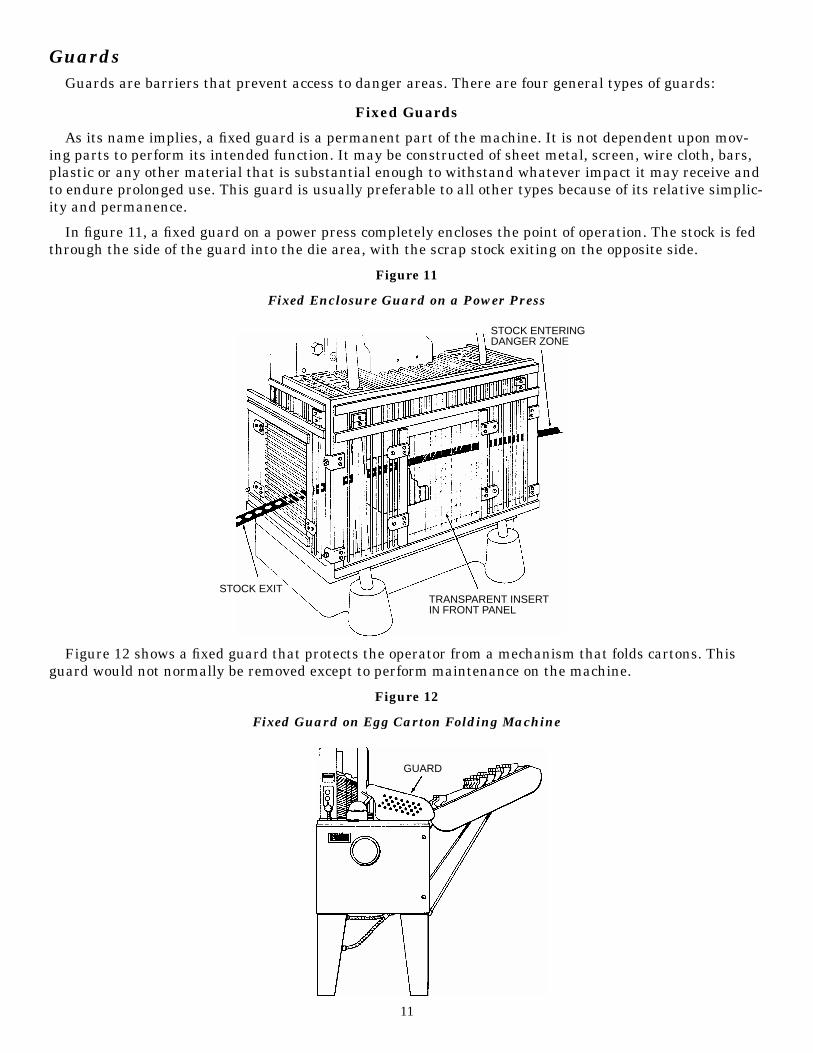
As its name implies, a fixed guard is a permanent part of the machine. It is not dependent upon mov-ing parts to perform its intended function. It may be constructed of sheet metal, screen, wire cloth, bars,plastic or any other material that is substantial enough to withstand whatever impact it may receive andto endure prolonged use. This guard is usually preferable to all other types because of its relative simplic-ity and permanence.
In figure 11, a fixed guard on a power press completely encloses the point of operation. The stock is fedthrough the side of the guard into the die area, with the scrap stock exiting on the opposite side.
Figure 11
Fixed Enclosure Guard on a Power Press
Figure 12 shows a fixed guard that protects the operator from a mechanism that folds cartons. Thisguard would not normally be removed except to perform maintenance on the machine.
Figure 12
Fixed Guard on Egg Carton Folding Machine
11
STOCK EXITTRANSPARENT INSERTIN FRONT PANEL
STOCK ENTERINGDANGER ZONE
GUARD
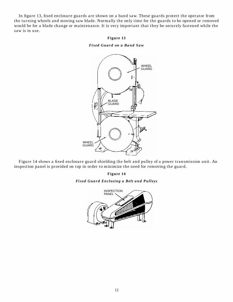
In figure 13, fixed enclosure guards are shown on a band saw. These guards protect the operator fromthe turning wheels and moving saw blade. Normally the only time for the guards to be opened or removedwould be for a blade change or maintenance. It is very important that they be securely fastened while thesaw is in use.
Figure 13
Fixed Guard on a Band Saw
Figure 14 shows a fixed enclosure guard shielding the belt and pulley of a power transmission unit. Aninspection panel is provided on top in order to minimize the need for removing the guard.
Figure 14
Fixed Guard Enclosing a Belt and Pulleys
12
WHEELGUARD
BLADEGUARD
WHEELGUARD
INSPECTIONPANEL
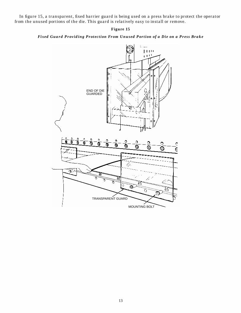
In figure 15, a transparent, fixed barrier guard is being used on a press brake to protect the operatorfrom the unused portions of the die. This guard is relatively easy to install or remove.
Figure 15
Fixed Guard Providing Protection From Unused Portion of a Die on a Press Brake
13
END OF DIEGUARDED
TRANSPARENT GUARD
MOUNTING BOLT

A fixed guard is shown on a veneer clipper in figure 16. This guard acts as a barrier, protecting fingersfrom exposure to the blade. Note the side view of the curved portion of the guard.
Figure 16
Fixed Guard on Veneer Clipper
Figure 17 shows both a fixed blade guard and a throat and gap guard on a power squaring shear. Theseguards should be removed only for maintenance or blade changes.
Figure 17
Fixed Guard on a Power Squaring Shear
14
GUARD
BLADE GUARD
THROAT ANDGAP GUARD

Interlocked Guards
When the interlocked guard is opened or removed, the tripping mechanism and/or power automaticallyshuts off or disengages, and the machine cannot cycle or be started until the guard is back in place.
An interlocked guard may use electrical, mechanical, hydraulic or pneumatic power or any combinationof these. Interlocks should not prevent “inching” by remote control, if required. Replacing the guardshould not automatically restart the machine.
Figure 18 shows an interlocked barrier guard mounted on an automatic bread bagging machine. Whenthe guard is removed, the machine will not function.
Figure 18
Interlocked Guard on Automatic Bread Bagging Machine
In figure 19, the beater mechanism of a picker machine (used in the textile industry) is covered by aninterlocked barrier guard. This guard cannot be raised while the machine is running, nor can themachine be restarted with the guard in the raised position.
Figure 19
Interlocked Guard on Picker Machine
15
GUARD
GUARD
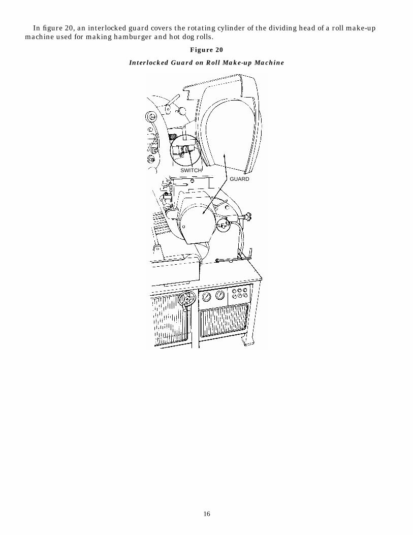
In figure 20, an interlocked guard covers the rotating cylinder of the dividing head of a roll make-upmachine used for making hamburger and hot dog rolls.
Figure 20
Interlocked Guard on Roll Make-up Machine
16
SWITCH
GUARD
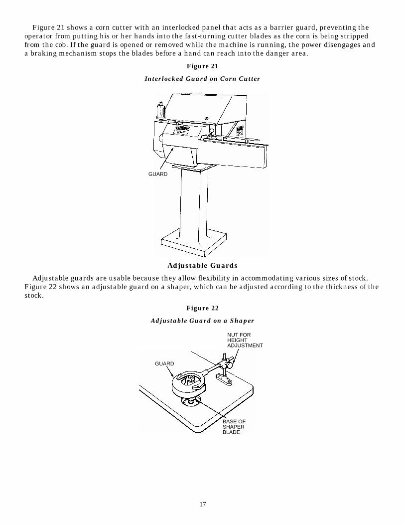
Figure 21 shows a corn cutter with an interlocked panel that acts as a barrier guard, preventing theoperator from putting his or her hands into the fast-turning cutter blades as the corn is being strippedfrom the cob. If the guard is opened or removed while the machine is running, the power disengages anda braking mechanism stops the blades before a hand can reach into the danger area.
Figure 21
Interlocked Guard on Corn Cutter
Adjustable Guards
Adjustable guards are usable because they allow flexibility in accommodating various sizes of stock.Figure 22 shows an adjustable guard on a shaper, which can be adjusted according to the thickness of thestock.
Figure 22
Adjustable Guard on a Shaper
17
GUARD
GUARD
NUT FORHEIGHTADJUSTMENT
BASE OFSHAPERBLADE
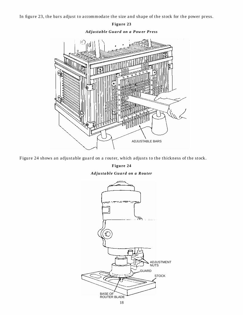
In figure 23, the bars adjust to accommodate the size and shape of the stock for the power press.
Figure 23
Adjustable Guard on a Power Press
Figure 24 shows an adjustable guard on a router, which adjusts to the thickness of the stock.
Figure 24
Adjustable Guard on a Router
18
ADJUSTABLE BARS
ADJUSTMENTNUTS
GUARD
STOCK
BASE OFROUTER BLADE

Figure 25 shows an adjustable enclosure guard on a band saw.
Figure 25
Adjustable Guard on a Band Saw
In figure 26, the guard adjusts to provide a barrier between the operator and the blade.
Figure 26
Adjustable Guard on a Table Saw
19
ADJUSTABLEBLADE GUARD
AIR HOSE
TRANSPARENTGUARD
BLADE
SAW TABLE
STOCK
SAW BLADE
HANDLE FOR EXTENDINGOR RETRACTING GUARD
OVER BLADE
CRANK FORHEIGHT ADJUSTMENT
GUARD

Figure 27 shows a band saw with an adjustable guard to protect the operator from the unused portionof the blade. This guard can be adjusted according to the size of stock.
Figure 27
Adjustable Guard on a Horizontal Band Saw
Self-Adjusting Guards
The openings of these barriers are determined by the movement of the stock. As the operator moves thestock into the danger area, the guard is pushed away, providing an opening that is only large enough toadmit the stock. After the stock is removed, the guard returns to the rest position. This guard protectsthe operator by placing a barrier between the danger area and the operator. The guards may be con-structed of plastic, metal or other substantial material. Self-adjusting guards offer different degrees ofprotection.
20
ADJUSTMENT KNOB
GUARD
BLADE
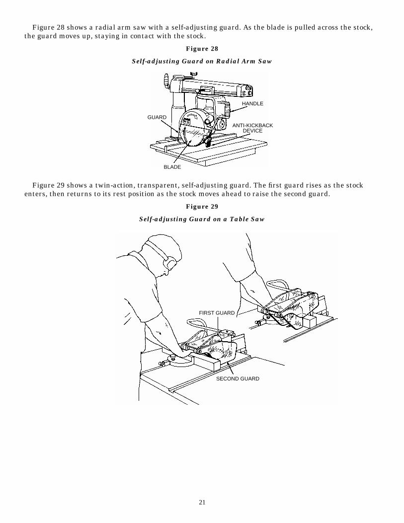
Figure 28 shows a radial arm saw with a self-adjusting guard. As the blade is pulled across the stock,the guard moves up, staying in contact with the stock.
Figure 28
Self-adjusting Guard on Radial Arm Saw
Figure 29 shows a twin-action, transparent, self-adjusting guard. The first guard rises as the stockenters, then returns to its rest position as the stock moves ahead to raise the second guard.
Figure 29
Self-adjusting Guard on a Table Saw
21
ANTI-KICKBACKDEVICE
BLADE
GUARD
HANDLE
FIRST GUARD
SECOND GUARD

A self-adjusting guard is shown in figure 30. As the blade moves through the stock, the guard rises upto the stock surface.
Figure 30
Self-adjusting Guard on a Circular Saw
22
GUARD RETRACTED
STOCK
BLADE
GUARD
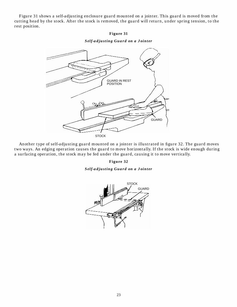
Figure 31 shows a self-adjusting enclosure guard mounted on a jointer. This guard is moved from thecutting head by the stock. After the stock is removed, the guard will return, under spring tension, to therest position.
Figure 31
Self-adjusting Guard on a Jointer
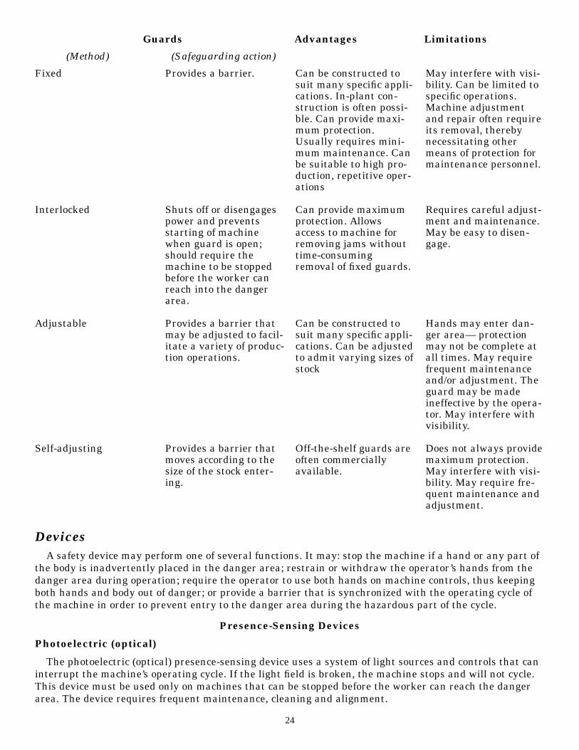
Another type of self-adjusting guard mounted on a jointer is illustrated in figure 32. The guard movestwo ways. An edging operation causes the guard to move horizontally. If the stock is wide enough duringa surfacing operation, the stock may be fed under the guard, causing it to move vertically.
Figure 32
Self-adjusting Guard on a Jointer
23
GUARD IN RESTPOSITION
STOCK
GUARD
STOCK
GUARD
DevicesA safety device may perform one of several functions. It may: stop the machine if a hand or any part of
the body is inadvertently placed in the danger area; restrain or withdraw the operator’s hands from thedanger area during operation; require the operator to use both hands on machine controls, thus keepingboth hands and body out of danger; or provide a barrier that is synchronized with the operating cycle ofthe machine in order to prevent entry to the danger area during the hazardous part of the cycle.
Presence-Sensing Devices
Photoelectric (optical)
The photoelectric (optical) presence-sensing device uses a system of light sources and controls that caninterrupt the machine’s operating cycle. If the light field is broken, the machine stops and will not cycle.This device must be used only on machines that can be stopped before the worker can reach the dangerarea. The device requires frequent maintenance, cleaning and alignment.
24
Fixed
Interlocked
Adjustable
Self-adjusting
Provides a barrier.
Shuts off or disengagespower and preventsstarting of machinewhen guard is open;should require themachine to be stoppedbefore the worker canreach into the dangerarea.
Provides a barrier thatmay be adjusted to facil-itate a variety of produc-tion operations.
Provides a barrier thatmoves according to thesize of the stock enter-ing.
Can be constructed tosuit many specific appli-cations. In-plant con-struction is often possi-ble. Can provide maxi-mum protection.Usually requires mini-mum maintenance. Canbe suitable to high pro-duction, repetitive oper-ations
Can provide maximumprotection. Allowsaccess to machine forremoving jams withouttime-consumingremoval of fixed guards.
Can be constructed tosuit many specific appli-cations. Can be adjustedto admit varying sizes ofstock
Off-the-shelf guards areoften commerciallyavailable.
May interfere with visi-bility. Can be limited tospecific operations.Machine adjustmentand repair often requireits removal, therebynecessitating othermeans of protection formaintenance personnel.
Requires careful adjust-ment and maintenance.May be easy to disen-gage.
Hands may enter dan-ger area— protectionmay not be complete atall times. May requirefrequent maintenanceand/or adjustment. Theguard may be madeineffective by the opera-tor. May interfere withvisibility.
Does not always providemaximum protection.May interfere with visi-bility. May require fre-quent maintenance andadjustment.
Guards Advantages Limitations
(Method) (Safeguarding action)

Figure 33 shows a photoelectric presence-sensing device on a part-revolution power press. When thelight beam is broken, either the ram will not start to cycle, or, if the press is already functioning, the stop-ping mechanism will be activated.
Figure 33
Photoelectric Presence-Sensing Device on Power Press
A photoelectric presence-sensing device used with a press brake is illustrated in figure 34. The devicemay be swung up or down to accommodate different production requirements.
Figure 34
Photoelectric Presence-Sensing Device on Press Brake
25
SENSING DEVICE
DANGER AREA
SENSING DEVICE
Radiofrequency (capacitance)
The radiofrequency (capacitance) presence-sensing device uses a radio beam that is part of the machinecontrol circuit. When the capacitance field is broken, the machine will stop or will not activate. Like thephotoelectric device, this device must only be used on machines that can be stopped before the worker canreach the danger area. This requires the machine to have a friction clutch or other reliable means forstopping.
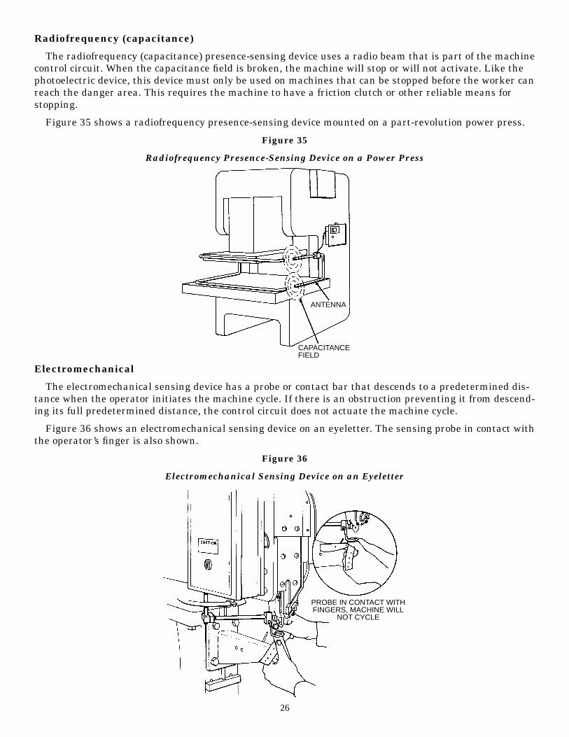
Figure 35 shows a radiofrequency presence-sensing device mounted on a part-revolution power press.
Figure 35
Radiofrequency Presence-Sensing Device on a Power Press
Electromechanical
The electromechanical sensing device has a probe or contact bar that descends to a predetermined dis-tance when the operator initiates the machine cycle. If there is an obstruction preventing it from descend-ing its full predetermined distance, the control circuit does not actuate the machine cycle.
Figure 36 shows an electromechanical sensing device on an eyeletter. The sensing probe in contact withthe operator’s finger is also shown.
Figure 36
Electromechanical Sensing Device on an Eyeletter
26
ANTENNA
CAPACITANCEFIELD
PROBE IN CONTACT WITHFINGERS, MACHINE WILL
NOT CYCLE
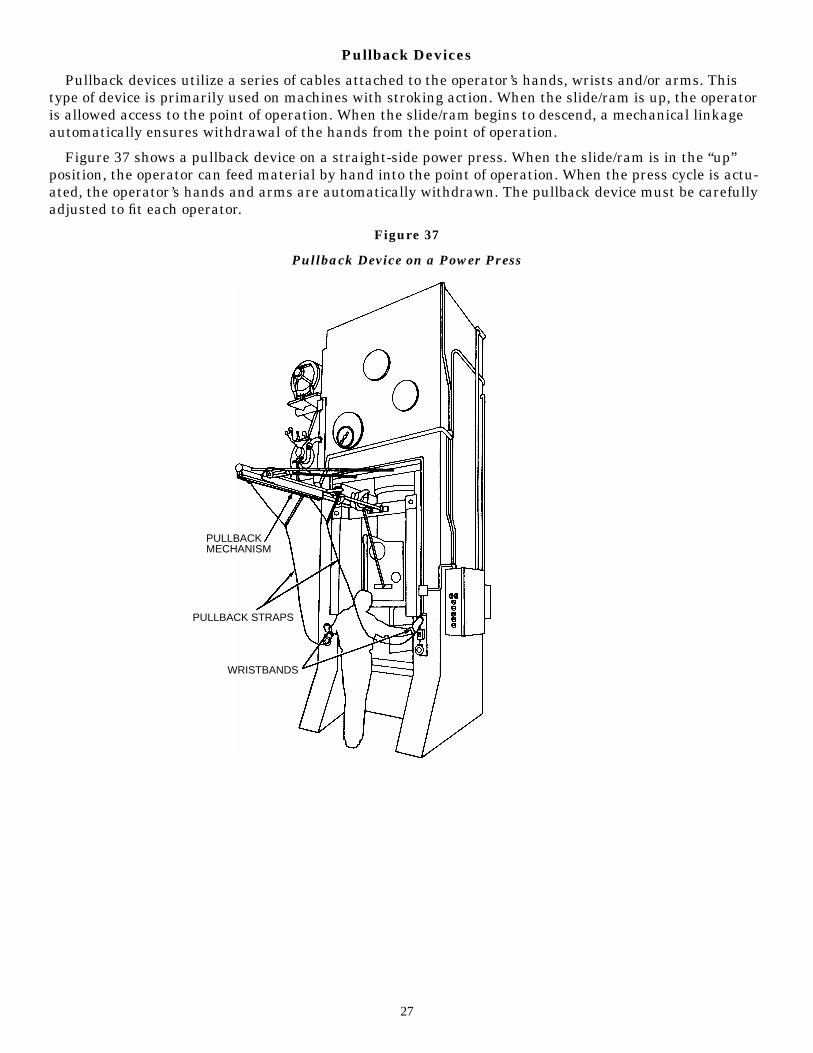
Pullback Devices
Pullback devices utilize a series of cables attached to the operator’s hands, wrists and/or arms. Thistype of device is primarily used on machines with stroking action. When the slide/ram is up, the operatoris allowed access to the point of operation. When the slide/ram begins to descend, a mechanical linkageautomatically ensures withdrawal of the hands from the point of operation.
Figure 37 shows a pullback device on a straight-side power press. When the slide/ram is in the “up”position, the operator can feed material by hand into the point of operation. When the press cycle is actu-ated, the operator’s hands and arms are automatically withdrawn. The pullback device must be carefullyadjusted to fit each operator.
Figure 37
Pullback Device on a Power Press
27
PULLBACKMECHANISM
PULLBACK STRAPS
WRISTBANDS
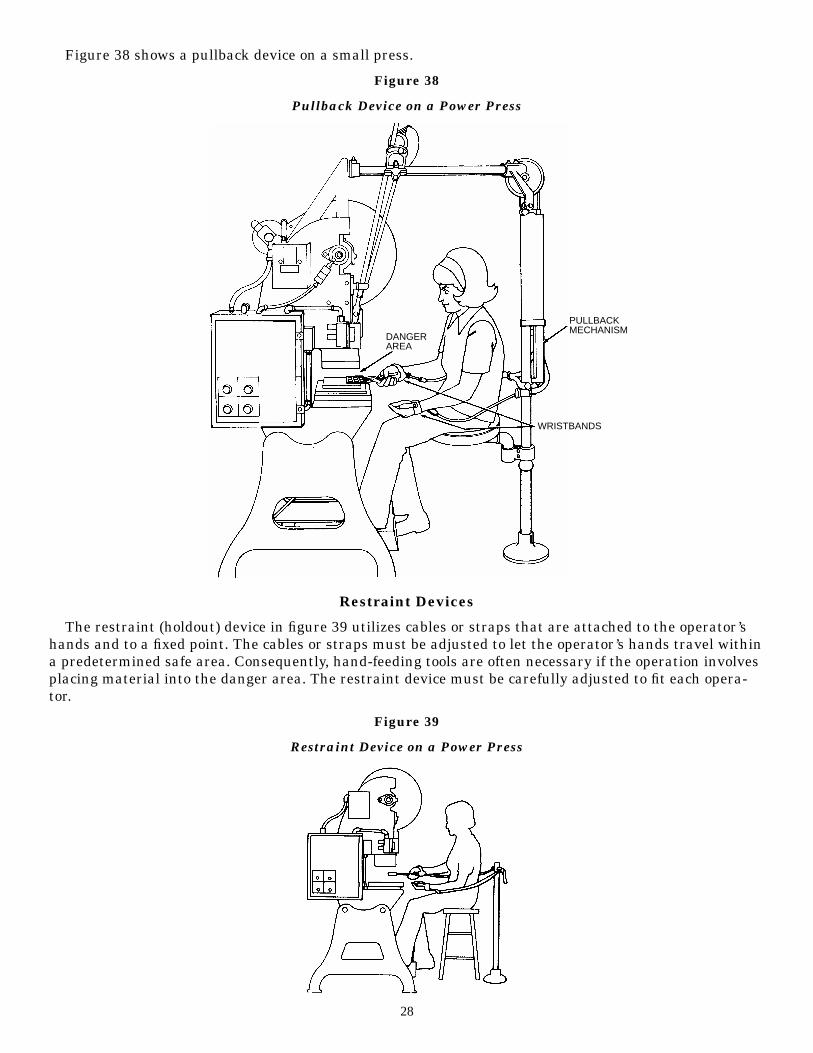
Figure 38 shows a pullback device on a small press.
Figure 38
Pullback Device on a Power Press
Restraint Devices
The restraint (holdout) device in figure 39 utilizes cables or straps that are attached to the operator’shands and to a fixed point. The cables or straps must be adjusted to let the operator’s hands travel withina predetermined safe area. Consequently, hand-feeding tools are often necessary if the operation involvesplacing material into the danger area. The restraint device must be carefully adjusted to fit each opera-tor.
Figure 39
Restraint Device on a Power Press
28
DANGERAREA
PULLBACKMECHANISM
WRISTBANDS
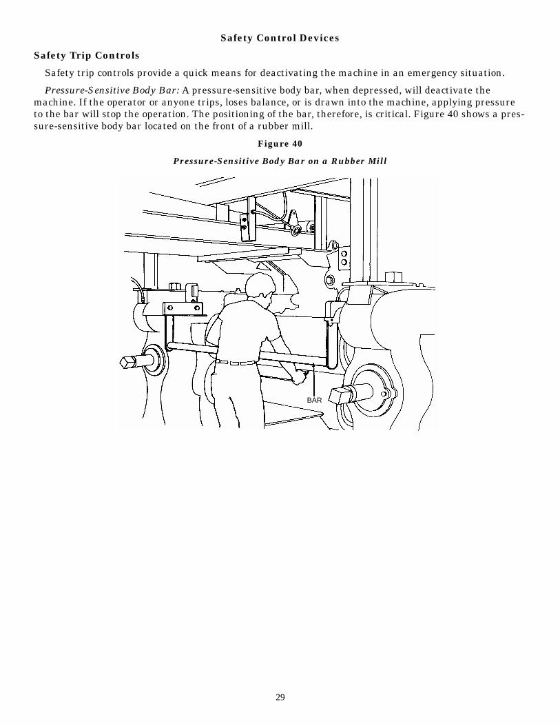
Safety Control Devices
Safety Trip Controls
Safety trip controls provide a quick means for deactivating the machine in an emergency situation.
Pressure-Sensitive Body Bar: A pressure-sensitive body bar, when depressed, will deactivate themachine. If the operator or anyone trips, loses balance, or is drawn into the machine, applying pressureto the bar will stop the operation. The positioning of the bar, therefore, is critical. Figure 40 shows a pres-sure-sensitive body bar located on the front of a rubber mill.
Figure 40
Pressure-Sensitive Body Bar on a Rubber Mill
29
BAR
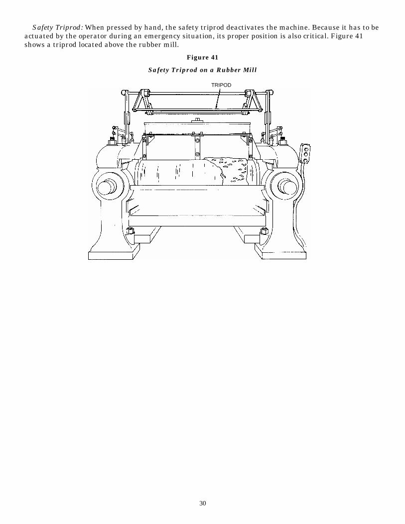
Safety Triprod: When pressed by hand, the safety triprod deactivates the machine. Because it has to beactuated by the operator during an emergency situation, its proper position is also critical. Figure 41shows a triprod located above the rubber mill.
Figure 41
Safety Triprod on a Rubber Mill
30
TRIPOD
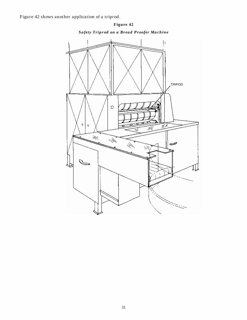
Figure 42 shows another application of a triprod.
Figure 42
Safety Triprod on a Bread Proofer Machine
31
TRIPOD
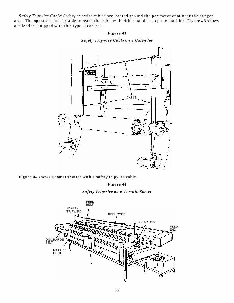
Safety Tripwire Cable: Safety tripwire cables are located around the perimeter of or near the dangerarea. The operator must be able to reach the cable with either hand to stop the machine. Figure 43 showsa calender equipped with this type of control.
Figure 43
Safety Tripwire Cable on a Calender
Figure 44 shows a tomato sorter with a safety tripwire cable.
Figure 44
Safety Tripwire on a Tomato Sorter
32
CABLE
SAFETYTRIPWIRE
FEEDBELT
DISCHARGEBELT
DISPOSALCHUTE
REEL CORE
GEAR BOX
FEEDEND
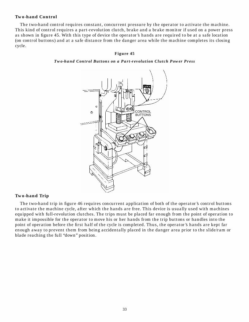
Two-hand Control
The two-hand control requires constant, concurrent pressure by the operator to activate the machine.This kind of control requires a part-revolution clutch, brake and a brake monitor if used on a power pressas shown in figure 45. With this type of device the operator’s hands are required to be at a safe location(on control buttons) and at a safe distance from the danger area while the machine completes its closingcycle.
Figure 45
Two-hand Control Buttons on a Part-revolution Clutch Power Press
Two-hand Trip
The two-hand trip in figure 46 requires concurrent application of both of the operator’s control buttonsto activate the machine cycle, after which the hands are free. This device is usually used with machinesequipped with full-revolution clutches. The trips must be placed far enough from the point of operation tomake it impossible for the operator to move his or her hands from the trip buttons or handles into thepoint of operation before the first half of the cycle is completed. Thus, the operator’s hands are kept farenough away to prevent them from being accidentally placed in the danger area prior to the slide/ram orblade reaching the full “down” position.
33
CONTROLBUTTONS
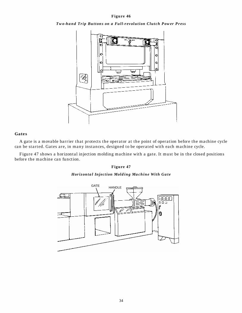
Figure 46
Two-hand Trip Buttons on a Full-revolution Clutch Power Press
Gates
A gate is a movable barrier that protects the operator at the point of operation before the machine cyclecan be started. Gates are, in many instances, designed to be operated with each machine cycle.
Figure 47 shows a horizontal injection molding machine with a gate. It must be in the closed positionsbefore the machine can function.
Figure 47
Horizontal Injection Molding Machine With Gate
34
GATE HANDLE
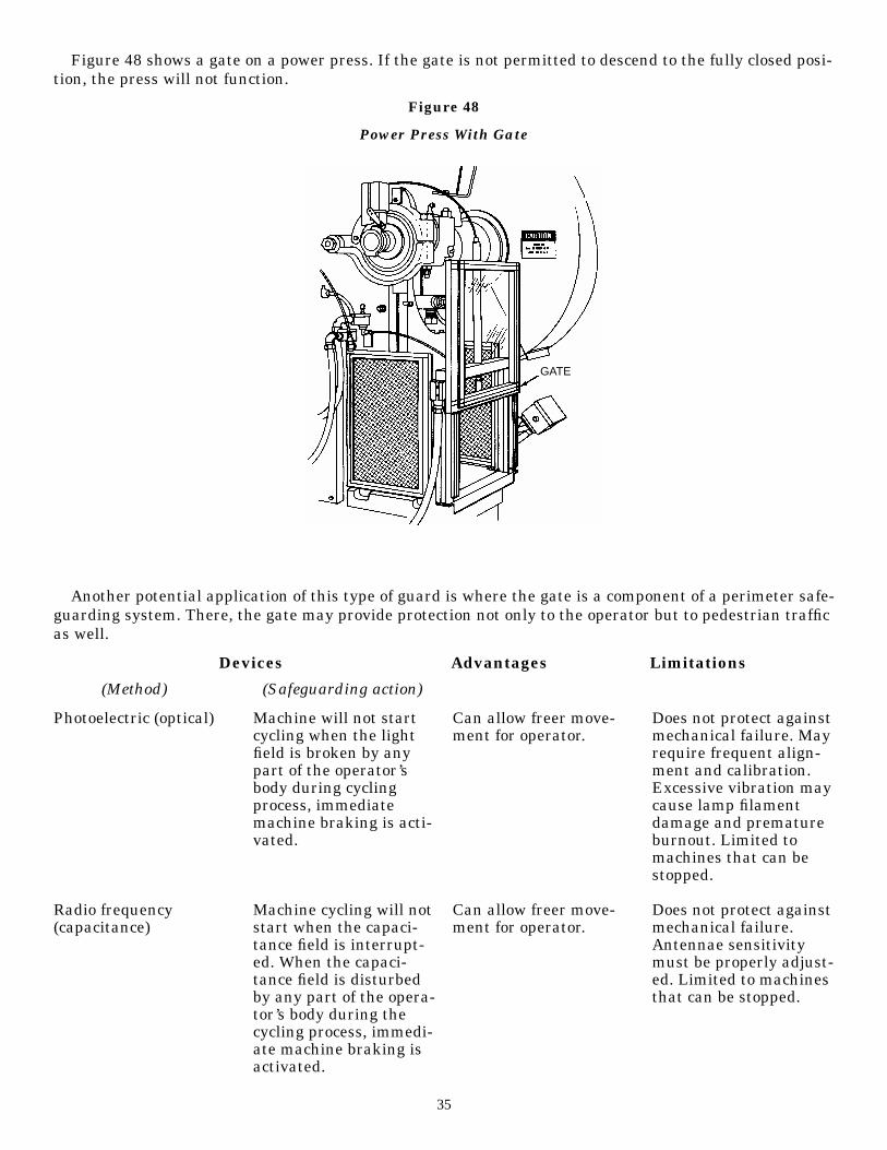
Figure 48 shows a gate on a power press. If the gate is not permitted to descend to the fully closed posi-tion, the press will not function.
Figure 48
Power Press With Gate
Another potential application of this type of guard is where the gate is a component of a perimeter safe-guarding system. There, the gate may provide protection not only to the operator but to pedestrian trafficas well.
35
GATE
Photoelectric (optical)
Radio frequency(capacitance)
Machine will not startcycling when the lightfield is broken by anypart of the operator’sbody during cyclingprocess, immediatemachine braking is acti-vated.
Machine cycling will notstart when the capaci-tance field is interrupt-ed. When the capaci-tance field is disturbedby any part of the opera-tor’s body during thecycling process, immedi-ate machine braking isactivated.
Can allow freer move-ment for operator.
Can allow freer move-ment for operator.
Does not protect againstmechanical failure. Mayrequire frequent align-ment and calibration.Excessive vibration maycause lamp filamentdamage and prematureburnout. Limited tomachines that can bestopped.
Does not protect againstmechanical failure.Antennae sensitivitymust be properly adjust-ed. Limited to machinesthat can be stopped.
Devices Advantages Limitations
(Method) (Safeguarding action)
36
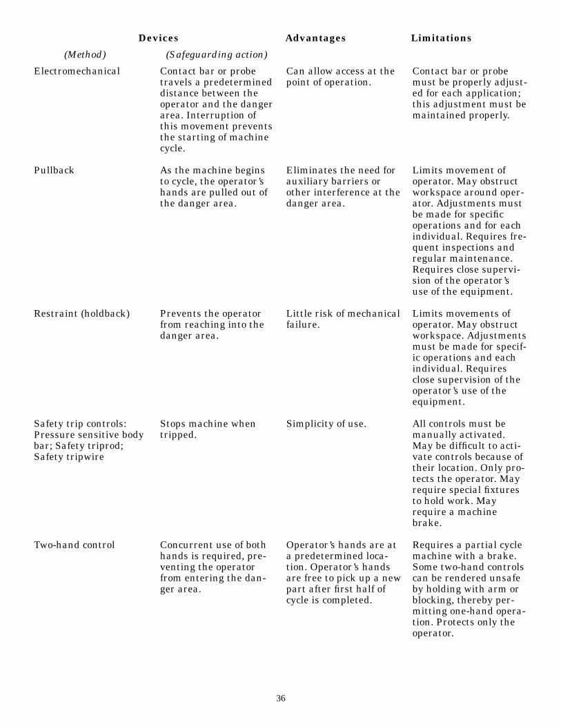
Electromechanical
Pullback
Restraint (holdback)
Safety trip controls:Pressure sensitive bodybar; Safety triprod;Safety tripwire
Two-hand control
Contact bar or probetravels a predetermineddistance between theoperator and the dangerarea. Interruption ofthis movement preventsthe starting of machinecycle.
As the machine beginsto cycle, the operator’shands are pulled out ofthe danger area.
Prevents the operatorfrom reaching into thedanger area.
Stops machine whentripped.
Concurrent use of bothhands is required, pre-venting the operatorfrom entering the dan-ger area.
Can allow access at thepoint of operation.
Eliminates the need forauxiliary barriers orother interference at thedanger area.
Little risk of mechanicalfailure.
Simplicity of use.
Operator’s hands are ata predetermined loca-tion. Operator’s handsare free to pick up a newpart after first half ofcycle is completed.
Contact bar or probemust be properly adjust-ed for each application;this adjustment must bemaintained properly.
Limits movement ofoperator. May obstructworkspace around oper-ator. Adjustments mustbe made for specificoperations and for eachindividual. Requires fre-quent inspections andregular maintenance.Requires close supervi-sion of the operator’suse of the equipment.
Limits movements ofoperator. May obstructworkspace. Adjustmentsmust be made for specif-ic operations and eachindividual. Requiresclose supervision of theoperator’s use of theequipment.
All controls must bemanually activated.May be difficult to acti-vate controls because oftheir location. Only pro-tects the operator. Mayrequire special fixturesto hold work. Mayrequire a machinebrake.
Requires a partial cyclemachine with a brake.Some two-hand controlscan be rendered unsafeby holding with arm orblocking, thereby per-mitting one-hand opera-tion. Protects only theoperator.
Devices Advantages Limitations
(Method) (Safeguarding action)
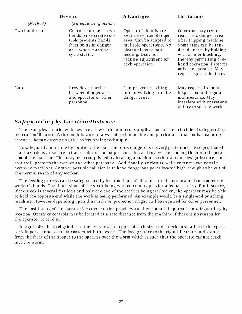
Safeguarding by Location/DistanceThe examples mentioned below are a few of the numerous applications of the principle of safeguarding
by location/distance. A thorough hazard analysis of each machine and particular situation is absolutelyessential before attempting this safeguarding technique.
To safeguard a machine by location, the machine or its dangerous moving parts must be so positionedthat hazardous areas are not accessible or do not present a hazard to a worker during the normal opera-tion of the machine. This may be accomplished by locating a machine so that a plant design feature, suchas a wall, protects the worker and other personnel. Additionally, enclosure walls or fences can restrictaccess to machines. Another possible solution is to have dangerous parts located high enough to be out ofthe normal reach of any worker.
The feeding process can be safeguarded by location if a safe distance can be maintained to protect theworker’s hands. The dimensions of the stock being worked on may provide adequate safety. For instance,if the stock is several feet long and only one end of the stock is being worked on, the operator may be ableto hold the opposite end while the work is being performed. An example would be a single-end punchingmachine. However depending upon the machine, protection might still be required for other personnel.
The positioning of the operator’s control station provides another potential approach to safeguarding bylocation. Operator controls may be located at a safe distance from the machine if there is no reason forthe operator to tend it.
In figure 49, the food grinder to the left shows a hopper of such size and a neck so small that the opera-tor’s fingers cannot come in contact with the worm. The food grinder to the right illustrates a distancefrom the front of the hopper to the opening over the worm which is such that the operator cannot reachinto the worm.
37
Two-hand trip
Gate
Concurrent use of twohands on separate con-trols prevents handsfrom being in dangerarea when machinecycle starts.
Provides a barrierbetween danger areaand operator or otherpersonnel.
Operator’s hands arekept away from dangerarea. Can be adapted tomultiple operations. Noobstructions to handfeeding. Does notrequire adjustment foreach operation.
Can prevent reachinginto or walking into thedanger area.
Operator may try toreach into danger areaafter tripping machine.Some trips can be ren-dered unsafe by holdingwith arm or blocking,thereby permitting one-hand operation. Protectsonly the operator. Mayrequire special features.
May require frequentinspection and regularmaintenance. Mayinterfere with operator’sability to see the work.
Devices Advantages Limitations
(Method) (Safeguarding action)

Figure 49
Food Grinders—Guarding by Position
Feeding and Ejection Methods to Improve Operator SafetyMany feeding and ejection methods do not require the operator to place his or her hands in the danger
area. In some cases, no operator involvement is necessary after the machine is set up. In other situations,operators can manually feed the stock with the assistance of a feeding mechanism. Properly designedejection methods do not require any operator involvement after the machine starts to function.
Some feeding and ejection methods may even create hazards themselves. For instance a robot mayeliminate the need for an operator to be near the machine but may create a new hazard itself by themovement of its arm.
Using these feeding and ejection methods does not eliminate the need for guards and devices. Guardsand devices must be used wherever they are necessary and possible in order to provide protection fromexposure to hazards.
Automatic Feeds
Automatic feeds reduce the exposure of the operator during the work process, and sometimes do notrequire any effort by the operator after the machine is set up and running.
In figure 50, the power press has an automatic feeding mechanism. Notice the transparent fixed enclo-sure guard at the danger area.
38
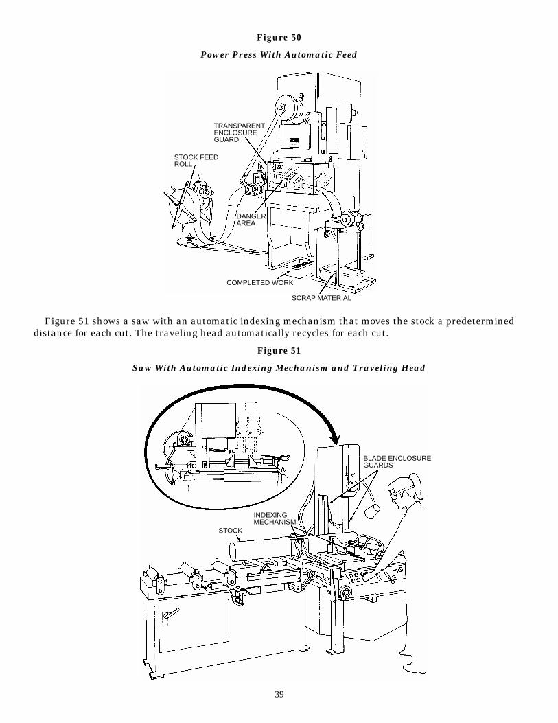
Figure 50
Power Press With Automatic Feed
Figure 51 shows a saw with an automatic indexing mechanism that moves the stock a predetermineddistance for each cut. The traveling head automatically recycles for each cut.
Figure 51
Saw With Automatic Indexing Mechanism and Traveling Head
39
TRANSPARENTENCLOSUREGUARD
STOCK FEEDROLL
DANGERAREA
COMPLETED WORK
SCRAP MATERIAL
BLADE ENCLOSUREGUARDS
INDEXINGMECHANISM
STOCK
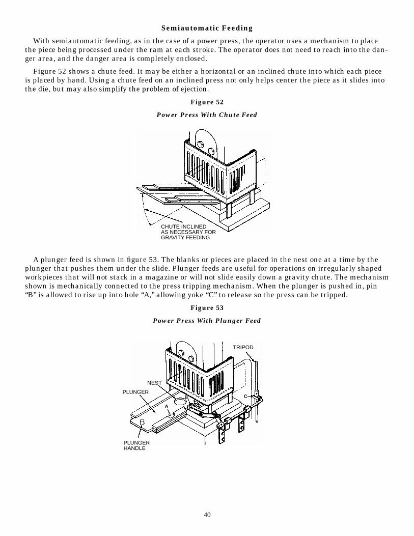
Semiautomatic Feeding
With semiautomatic feeding, as in the case of a power press, the operator uses a mechanism to placethe piece being processed under the ram at each stroke. The operator does not need to reach into the dan-ger area, and the danger area is completely enclosed.
Figure 52 shows a chute feed. It may be either a horizontal or an inclined chute into which each pieceis placed by hand. Using a chute feed on an inclined press not only helps center the piece as it slides intothe die, but may also simplify the problem of ejection.
Figure 52
Power Press With Chute Feed
A plunger feed is shown in figure 53. The blanks or pieces are placed in the nest one at a time by theplunger that pushes them under the slide. Plunger feeds are useful for operations on irregularly shapedworkpieces that will not stack in a magazine or will not slide easily down a gravity chute. The mechanismshown is mechanically connected to the press tripping mechanism. When the plunger is pushed in, pin“B” is allowed to rise up into hole “A,” allowing yoke “C” to release so the press can be tripped.
Figure 53
Power Press With Plunger Feed
40
CHUTE INCLINEDAS NECESSARY FORGRAVITY FEEDING
TRIPOD
NEST
PLUNGER
PLUNGERHANDLE
A
B C
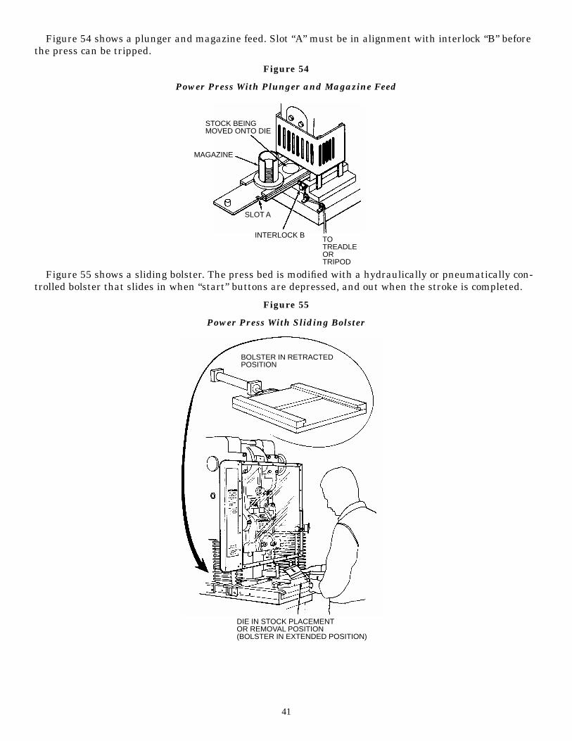
Figure 54 shows a plunger and magazine feed. Slot “A” must be in alignment with interlock “B” beforethe press can be tripped.
Figure 54
Power Press With Plunger and Magazine Feed
Figure 55 shows a sliding bolster. The press bed is modified with a hydraulically or pneumatically con-trolled bolster that slides in when “start” buttons are depressed, and out when the stroke is completed.
Figure 55
Power Press With Sliding Bolster
41
STOCK BEINGMOVED ONTO DIE
MAGAZINE
SLOT A
INTERLOCK B TOTREADLEORTRIPOD
BOLSTER IN RETRACTEDPOSITION
DIE IN STOCK PLACEMENTOR REMOVAL POSITION(BOLSTER IN EXTENDED POSITION)
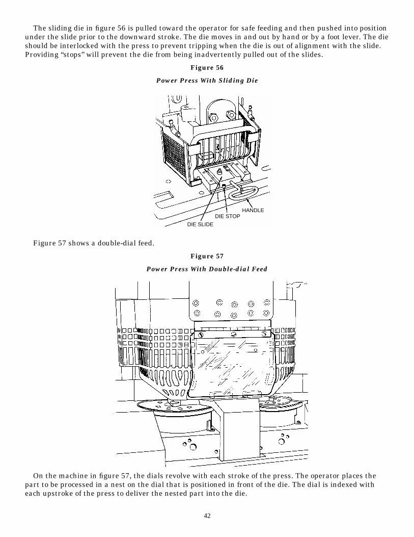
The sliding die in figure 56 is pulled toward the operator for safe feeding and then pushed into positionunder the slide prior to the downward stroke. The die moves in and out by hand or by a foot lever. The dieshould be interlocked with the press to prevent tripping when the die is out of alignment with the slide.Providing “stops” will prevent the die from being inadvertently pulled out of the slides.
Figure 56
Power Press With Sliding Die
Figure 57 shows a double-dial feed.
Figure 57
Power Press With Double-dial Feed
On the machine in figure 57, the dials revolve with each stroke of the press. The operator places thepart to be processed in a nest on the dial that is positioned in front of the die. The dial is indexed witheach upstroke of the press to deliver the nested part into the die.
42
DIE SLIDE
DIE STOPHANDLE
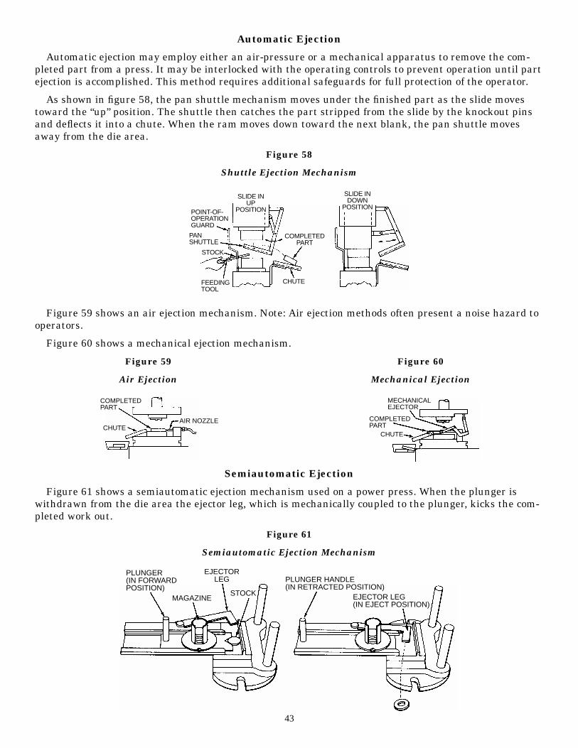
Automatic Ejection
Automatic ejection may employ either an air-pressure or a mechanical apparatus to remove the com-pleted part from a press. It may be interlocked with the operating controls to prevent operation until partejection is accomplished. This method requires additional safeguards for full protection of the operator.
As shown in figure 58, the pan shuttle mechanism moves under the finished part as the slide movestoward the “up” position. The shuttle then catches the part stripped from the slide by the knockout pinsand deflects it into a chute. When the ram moves down toward the next blank, the pan shuttle movesaway from the die area.
Figure 58
Shuttle Ejection Mechanism
Figure 59 shows an air ejection mechanism. Note: Air ejection methods often present a noise hazard tooperators.
Figure 60 shows a mechanical ejection mechanism.
Figure 59 Figure 60
Air Ejection Mechanical Ejection
Semiautomatic Ejection
Figure 61 shows a semiautomatic ejection mechanism used on a power press. When the plunger iswithdrawn from the die area the ejector leg, which is mechanically coupled to the plunger, kicks the com-pleted work out.
Figure 61
Semiautomatic Ejection Mechanism
43
SLIDE INUP
POSITION
SLIDE INDOWN
POSITION
COMPLETEDPART
POINT-OF-OPERATIONGUARD
PANSHUTTLE
STOCK
FEEDINGTOOL
CHUTE
COMPLETEDPART
CHUTEAIR NOZZLE
MECHANICALEJECTOR
COMPLETEDPART
CHUTE
PLUNGER(IN FORWARDPOSITION)
MAGAZINE
EJECTORLEG
STOCK
PLUNGER HANDLE(IN RETRACTED POSITION)
EJECTOR LEG(IN EJECT POSITION)
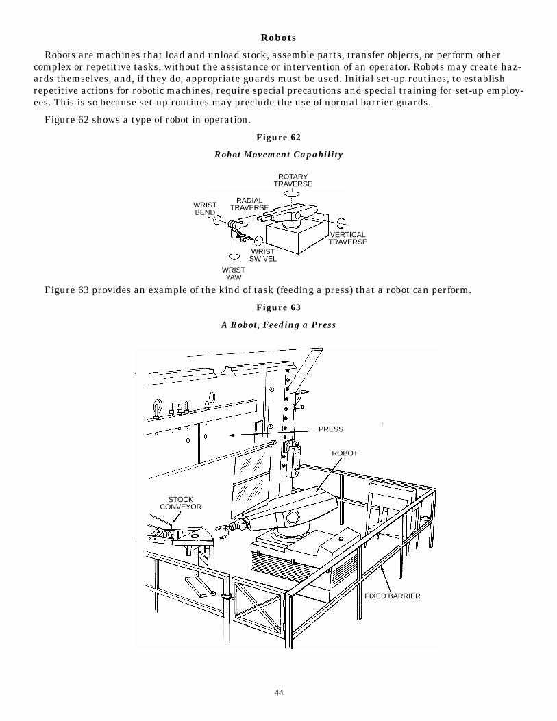
Robots
Robots are machines that load and unload stock, assemble parts, transfer objects, or perform othercomplex or repetitive tasks, without the assistance or intervention of an operator. Robots may create haz-ards themselves, and, if they do, appropriate guards must be used. Initial set-up routines, to establishrepetitive actions for robotic machines, require special precautions and special training for set-up employ-ees. This is so because set-up routines may preclude the use of normal barrier guards.
Figure 62 shows a type of robot in operation.
Figure 62
Robot Movement Capability
Figure 63 provides an example of the kind of task (feeding a press) that a robot can perform.
Figure 63
A Robot, Feeding a Press
44
WRISTBEND
RADIALTRAVERSE
ROTARYTRAVERSE
WRISTSWIVEL
WRISTYAW
VERTICALTRAVERSE
PRESS
ROBOT
FIXED BARRIER
STOCKCONVEYOR
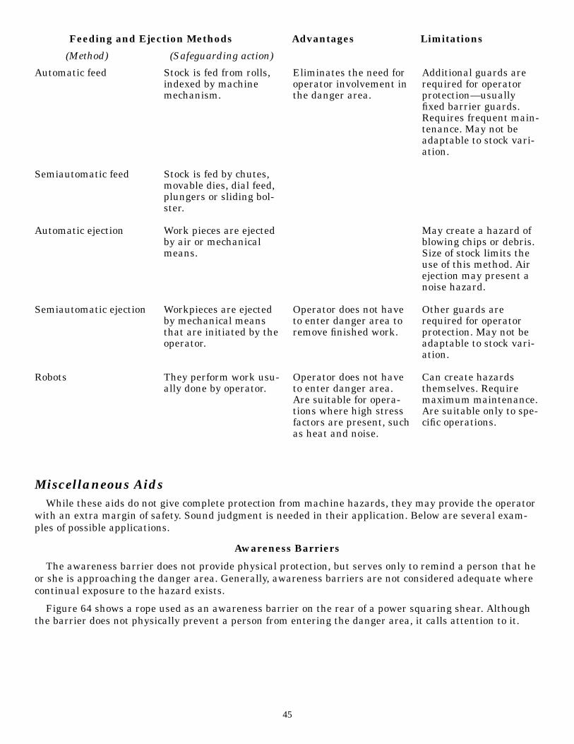
Miscellaneous AidsWhile these aids do not give complete protection from machine hazards, they may provide the operator
with an extra margin of safety. Sound judgment is needed in their application. Below are several exam-ples of possible applications.
Awareness Barriers
The awareness barrier does not provide physical protection, but serves only to remind a person that heor she is approaching the danger area. Generally, awareness barriers are not considered adequate wherecontinual exposure to the hazard exists.
Figure 64 shows a rope used as an awareness barrier on the rear of a power squaring shear. Althoughthe barrier does not physically prevent a person from entering the danger area, it calls attention to it.
45
Automatic feed
Semiautomatic feed
Automatic ejection
Semiautomatic ejection
Robots
Stock is fed from rolls,indexed by machinemechanism.
Stock is fed by chutes,movable dies, dial feed,plungers or sliding bol-ster.
Work pieces are ejectedby air or mechanicalmeans.
Workpieces are ejectedby mechanical meansthat are initiated by theoperator.
They perform work usu-ally done by operator.
Eliminates the need foroperator involvement inthe danger area.
Operator does not haveto enter danger area toremove finished work.
Operator does not haveto enter danger area.Are suitable for opera-tions where high stressfactors are present, suchas heat and noise.
Additional guards arerequired for operatorprotection—usuallyfixed barrier guards.Requires frequent main-tenance. May not beadaptable to stock vari-ation.
May create a hazard ofblowing chips or debris.Size of stock limits theuse of this method. Airejection may present anoise hazard.
Other guards arerequired for operatorprotection. May not beadaptable to stock vari-ation.
Can create hazardsthemselves. Requiremaximum maintenance.Are suitable only to spe-cific operations.
Feeding and Ejection Methods Advantages Limitations
(Method) (Safeguarding action)
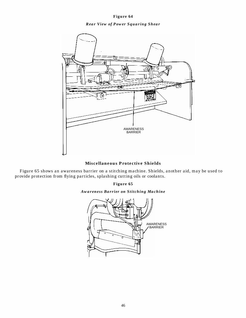
Figure 64
Rear View of Power Squaring Shear
Miscellaneous Protective Shields
Figure 65 shows an awareness barrier on a stitching machine. Shields, another aid, may be used toprovide protection from flying particles, splashing cutting oils or coolants.
Figure 65
Awareness Barrier on Stitching Machine
46
AWARENESSBARRIER
AWARENESSBARRIER
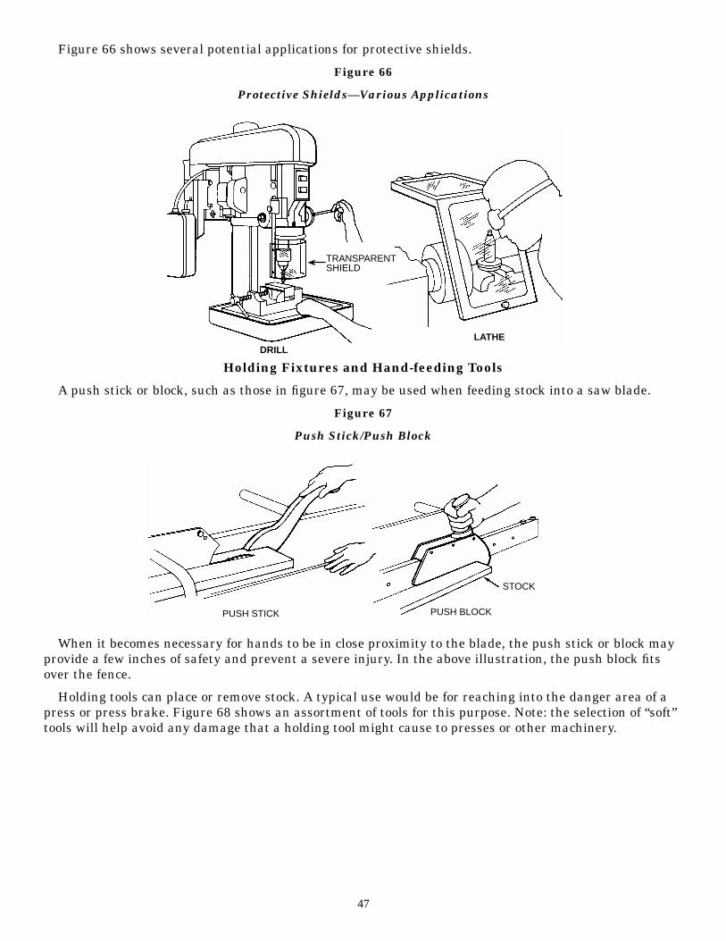
Figure 66 shows several potential applications for protective shields.
Figure 66
Protective Shields—Various Applications
Holding Fixtures and Hand-feeding Tools
A push stick or block, such as those in figure 67, may be used when feeding stock into a saw blade.
Figure 67
Push Stick/Push Block
When it becomes necessary for hands to be in close proximity to the blade, the push stick or block mayprovide a few inches of safety and prevent a severe injury. In the above illustration, the push block fitsover the fence.
Holding tools can place or remove stock. A typical use would be for reaching into the danger area of apress or press brake. Figure 68 shows an assortment of tools for this purpose. Note: the selection of “soft”tools will help avoid any damage that a holding tool might cause to presses or other machinery.
47
TRANSPARENTSHIELD
DRILLLATHE
PUSH STICK PUSH BLOCK
STOCK
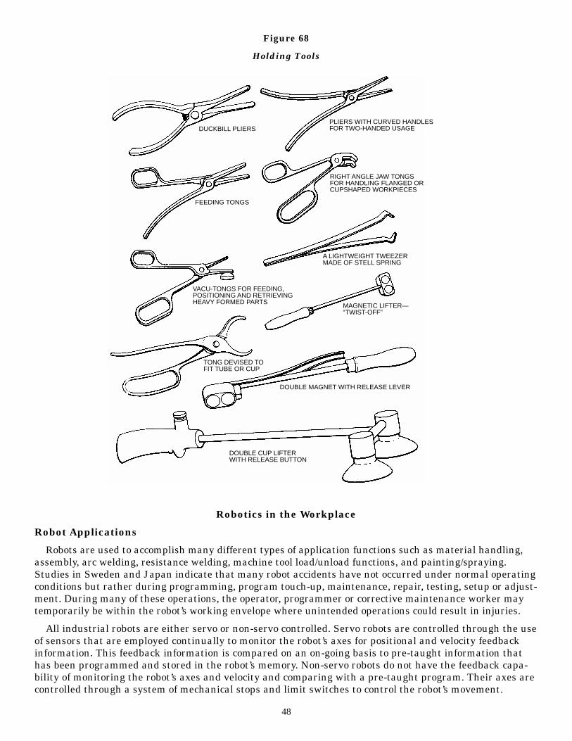
Figure 68
Holding Tools
Robotics in the Workplace
Robot Applications
Robots are used to accomplish many different types of application functions such as material handling,assembly, arc welding, resistance welding, machine tool load/unload functions, and painting/spraying.Studies in Sweden and Japan indicate that many robot accidents have not occurred under normal operatingconditions but rather during programming, program touch-up, maintenance, repair, testing, setup or adjust-ment. During many of these operations, the operator, programmer or corrective maintenance worker maytemporarily be within the robot’s working envelope where unintended operations could result in injuries.
All industrial robots are either servo or non-servo controlled. Servo robots are controlled through the useof sensors that are employed continually to monitor the robot’s axes for positional and velocity feedbackinformation. This feedback information is compared on an on-going basis to pre-taught information thathas been programmed and stored in the robot’s memory. Non-servo robots do not have the feedback capa-bility of monitoring the robot’s axes and velocity and comparing with a pre-taught program. Their axes arecontrolled through a system of mechanical stops and limit switches to control the robot’s movement.
48
DUCKBILL PLIERS
FEEDING TONGS
PLIERS WITH CURVED HANDLESFOR TWO-HANDED USAGE
RIGHT ANGLE JAW TONGSFOR HANDLING FLANGED ORCUPSHAPED WORKPIECES
A LIGHTWEIGHT TWEEZERMADE OF STELL SPRING
MAGNETIC LIFTER—“TWIST-OFF”
VACU-TONGS FOR FEEDING,POSITIONING AND RETRIEVINGHEAVY FORMED PARTS
TONG DEVISED TOFIT TUBE OR CUP
DOUBLE MAGNET WITH RELEASE LEVER
DOUBLE CUP LIFTERWITH RELEASE BUTTON
Type of Potential Hazards
The use of robotics in the workplace can also pose potential mechanical and human hazards.Mechanical hazards might include workers colliding with equipment, being crushed or trapped by equip-ment, or being injured by falling equipment components. For example, a worker could collide with therobot’s arm or peripheral equipment as a result of unpredicted movements, component malfunctions orunpredicted program changes. A worker could be injured by being trapped between the robot’s arm andother peripheral equipment or being crushed by peripheral equipment as a result of being impacted bythe robot into this equipment.
Mechanical hazards can also result from the mechanical failure of components associated with therobot or its power source, drive components, tooling or end-effector, and/or peripheral equipment. Possiblehazards include the failure of gripper mechanisms with resultant release of parts or the failure of end-effector power tools such as grinding wheels, buffing wheels, deburring tools, power screwdrivers, and nutrunners.
Human errors can result in hazards both to personnel and equipment. Errors in programming, inter-facing peripheral equipment and connecting input/output sensors can all result in unpredicted movementor action by the robot, which can result in personnel injury or equipment breakage. Human errors injudgment result frequently from incorrectly activating the teach pendant or control panel. The greatesthuman judgment error results from becoming so familiar with the robot’s redundant motions that person-nel are too trusting in assuming the nature of these motions and place themselves in hazardous positionswhile programming or performing maintenance within the robot’s work envelope.
Robots in the workplace are generally associated with the machine tools or process equipment. Robotsare machines and as such must be safeguarded in ways similar to those presented for any hazardousremotely controlled machine.
Various techniques are available to prevent employee exposure to the hazards that can be imposed byrobots. The most common technique is through the installation of perimeter guarding with interlockedgates. A critical parameter relates to the manner in which the interlocks function. Of major concern iswhether the computer program, control circuit or the primary power circuit is interrupted when an inter-lock is activated. The various industry standards should be investigated for guidance; however, it is gen-erally accepted that the primary motive power to the robot should be interrupted by the interlock.
The ANSI safety standard for industrial robots, ANSI/RIA R15.06-1986, is very informative and pre-sents certain basic requirements for protecting the worker. However, when a robot is to be used in aworkplace, the employer should accomplish a comprehensive operational safety/health hazard analysisand then devise and implement an effective safeguarding system that is fully responsive to the situation.(Various effective safeguarding techniques are described in ANSI B11.19-1990.)
The Utilization of Industry Consensus Standards
OSHA uses industry consensus standards, related to the safe operation of equipment, as guidance ofthe industry accepted practice for safe operations. Industry consensus standards that describe equipmentconfiguration or design but that do not describe safe and/or healthful use and operation of the equipmentare of limited assistance to OSHA. In any event, even when an industry consensus standard addressessafety/health considerations, OSHA may determine that the safety/health practices described by thatindustry consensus standard are deficient when related to the requirement(s) set forth by the pertinentOSHA regulation(s). However, many of the various ANSI safety standards devoted to the safe use ofequipment and machines are pertinent and provide valuable guidance as they relate to the multitude ofsafe operating procedures regularly discussed in ANSI safety standards.
All of the requirements of 29 CFR 1910.212, are applicable to machines found in industry. Paragraph(a)(1) requires that employees be protected from the hazards created by the point of operation, ingoingnip points, and rotating parts. Paragraph (a)(2) describes the manner in which guards shall be affixed.The proper application of devices are not described; therefore, other similar OSHA or pertinent industrystandards must be referred to for guidance. Paragraph (a)(3) describes, with particularity, the require-ments for safeguarding the point of operation.
49
The OSHA standard specifically requires that at the point of operation, “the guarding device shall be inconformity with any appropriate standards therefore, or in the absence of applicable specific standards,shall be so designed and constructed as to prevent the operator from having any part of his body in thedanger zone during the operating cycle.” Applicable standards include any similar OSHA standard or anyOSHA adopted industry consensus standards that provide for the safety of the operator during the oper-ating cycle. However, any specific industry consensus standard, such as an ANSI standard for the partic-ular machine or equipment, should be used for guidance relative to the accepted procedures for safe-guarding workers and operators from the recognized hazards of the equipment.
OSHA encourages employers to abide by the more current industry consensus standards since thosestandards are more likely to be abreast of the state of the art than an applicable OSHA standard may be.Employers who comply with the requirements of an industry consensus standard, where such compliancedeviates from the requirements of OSHA standard, should satisfy the intent of OSHA standard wheresuch compliance provides equal or more conservative safeguarding concept as compared to a specificOSHA standard. Furthermore, the industry consensus standards will usually discuss a variety of tech-niques for averting exposure to the identified hazards of the machine or process.
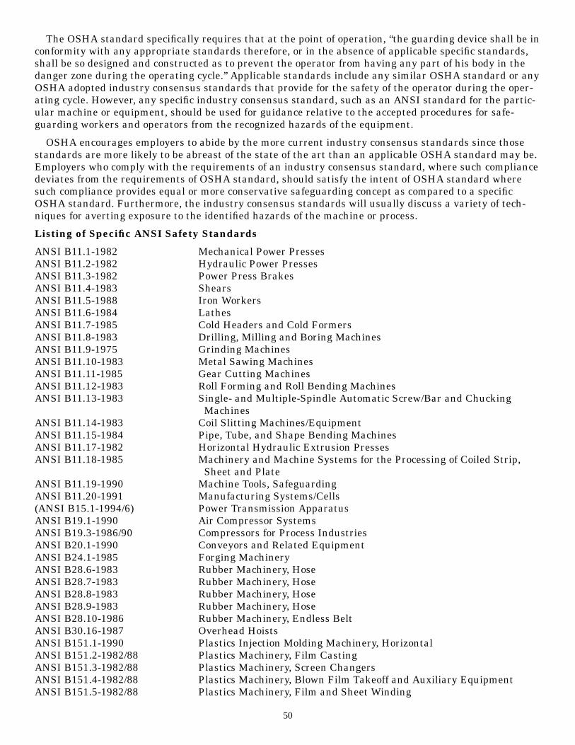
Listing of Specific ANSI Safety Standards
ANSI B11.1-1982 Mechanical Power PressesANSI B11.2-1982 Hydraulic Power PressesANSI B11.3-1982 Power Press BrakesANSI B11.4-1983 ShearsANSI B11.5-1988 Iron WorkersANSI B11.6-1984 LathesANSI B11.7-1985 Cold Headers and Cold FormersANSI B11.8-1983 Drilling, Milling and Boring MachinesANSI B11.9-1975 Grinding MachinesANSI B11.10-1983 Metal Sawing MachinesANSI B11.11-1985 Gear Cutting MachinesANSI B11.12-1983 Roll Forming and Roll Bending MachinesANSI B11.13-1983 Single- and Multiple-Spindle Automatic Screw/Bar and Chucking
MachinesANSI B11.14-1983 Coil Slitting Machines/EquipmentANSI B11.15-1984 Pipe, Tube, and Shape Bending MachinesANSI B11.17-1982 Horizontal Hydraulic Extrusion PressesANSI B11.18-1985 Machinery and Machine Systems for the Processing of Coiled Strip,
Sheet and PlateANSI B11.19-1990 Machine Tools, SafeguardingANSI B11.20-1991 Manufacturing Systems/Cells(ANSI B15.1-1994/6) Power Transmission ApparatusANSI B19.1-1990 Air Compressor SystemsANSI B19.3-1986/90 Compressors for Process IndustriesANSI B20.1-1990 Conveyors and Related EquipmentANSI B24.1-1985 Forging MachineryANSI B28.6-1983 Rubber Machinery, HoseANSI B28.7-1983 Rubber Machinery, HoseANSI B28.8-1983 Rubber Machinery, HoseANSI B28.9-1983 Rubber Machinery, HoseANSI B28.10-1986 Rubber Machinery, Endless BeltANSI B30.16-1987 Overhead HoistsANSI B151.1-1990 Plastics Injection Molding Machinery, HorizontalANSI B151.2-1982/88 Plastics Machinery, Film CastingANSI B151.3-1982/88 Plastics Machinery, Screen ChangersANSI B151.4-1982/88 Plastics Machinery, Blown Film Takeoff and Auxiliary EquipmentANSI B151.5-1982/88 Plastics Machinery, Film and Sheet Winding
50

ANSI B151.6-1982/88 Plastics Machinery, Slit Tape and Monofilament PostextrusionEquipment
ANSI B151.7-1982/88 Plastics and Rubber Extrusion MachineryANSI B151.11-1982 Plastics Machinery, Granulators, Pelletizers and DicersANSI B151.15-1985 Plastics Machinery, Extrusion Blow MoldingANSI B151.21-1986 Plastics Machinery, Injection Blow MoldingANSI B151.25-1988 Plastics Machinery, Injection MoldingANSI B152.2-1982 Permanent-Mold Casting Machines (Other Than Gray Iron)ANSI B153.1-1990 Automotive LiftsANSI B155.1-1986 Packaging MachineryANSI B169.1-1990 Envelope Manufacturing MachineryANSI B176-1985 Copper-Alloy DiecastingANSI B177.2-1977/82 Printing Ink Vertical Post MixersANSI/NEMA ICS2:225.95-1983 Interlocking Control Circuits for Personnel ProtectionANSI/NFPA 79-1991 Electrical Standard for Industrial MachineryANSI/RIA R15.06-1986 Industrial Robots and Robot SystemsANSI Z8.1-1972 Commercial Laundry and Dry-Cleaning EquipmentANSI Z241.1-1989 Foundry, Sand Preparation, Molding and Core-MakingANSI Z241.2-1989 Foundry, Melting and Pouring of MetalsANSI Z241.3-1989 Foundry, Cleaning and Finishing of CastingsANSI Z245.1-1984 Refuse Collecting and Compacting EquipmentANSI Z245.3-1977/83 Stability of Refuse BinsANSI Z245.5-1982 Bailing EquipmentANSI Z268.1-1082 Metal Scrap Processing Equipment
51
3Guard Construction
Today, many builders of single-purpose machines provide point-of-operation and power transmissionsafeguards as standard equipment. Not all machines have built-in safeguards provided by manufactur-ers; some must be specified in the purchase agreements.
Guards designed and installed by the builder offer two main advantages:
• They usually conform to the design and function of the machine.
• They can be designed to strengthen the machine in some way or to serve some additional functionalpurposes.
User-built guards are sometimes necessary for a variety of reasons. They have these advantages:
• Often, with older machinery, they are the only practical solution.
• They may be the only choice for mechanical power transmission apparatus in older plants, wheremachinery is not powered by individual motor drive.
• They permit options for point-of-operation safeguards when skilled personnel and machinery areavailable to make them.
• They can be designed and built to fit unique and even changing situations.
• They can be installed on individual dies and feeding mechanisms.
• Design and installation of machine safeguards by plant personnel can help to promote safety con-sciousness in the workplace.
However, they also have disadvantages:
• User-built guards may not conform well to the configuration and function of the machine.
• There is a risk that user-built guards may be poorly designed or built.
Point-of-Operation GuardsPoint-of-operation guarding is complicated by the number and complexity of machines and also by the
different uses for individual machines. For these reasons, not all machine builders provide point-of-opera-tion guards on their products. In many cases, a point-of-operation guard can only be made and installedby the user after a thorough hazard analysis of the work requirements.
Because abrasive wheels are so pervasive, and because of the incidence of amputations from powerpress injuries, special attention is given here to the selection, positioning and construction of guards forgrinders and mechanical power presses.
Grinders
Figure 69 shows a properly guarded abrasive wheel. Following figure 69 is discussion of the properlyguarded grinder. In addition to proper guarding the grinder operator would wear goggles or a face shield.
52

Figure 69
Properly Guarded Abrasive Wheel
Wheel safety guards cover the spindle end, nut and flange projections. The exposed area of the grindingwheel does not exceed more than one-fourth of the area of the entire wheel. Note: when the guard open-ing is measured, the visors and other accessory equipment are not included as part of the guard unlessthey are as strong as the guard.
The work or tool rest is of strong construction and is adjustable to compensate for wheel wear. Thework rest is kept closely adjusted to the wheel, to prevent the work from becoming jammed between thewheel and the work rest. The maximum clearance between the wheel and the work rest is 1/8 inch.
The tongue guards (upper peripheral guards) are constructed so that they adjust to the wheel as itwears down. A maximum clearance of 1/4 inch is allowed between the wheel and the tongue guard.
Figure 70 shows portable abrasive wheels, which should also be guarded by as complete an enclosureas practical. The operator of a portable grinder would also wear goggles or a face shield.
Figure 70
Portable Abrasive Wheels
Mechanical Power Presses
Below are facts that should be observed by any person who operates or requires the operation of powerpresses.
11. Figure 71 shows the distances that guards should be positioned from the point of operation, inaccordance with the required openings.
53
ADJUSTABLETONGUEGUARD
1/4" MAX.
FLANGE
SPINDALEGUARD
WORKREST
1/8" MAX.
EYE SHIELD
1/8
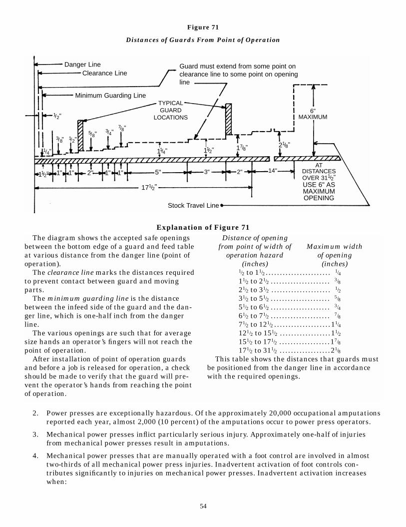
Figure 71
Distances of Guards From Point of Operation
Explanation of Figure 71
12. Power presses are exceptionally hazardous. Of the approximately 20,000 occupational amputationsreported each year, almost 2,000 (10 percent) of the amputations occur to power press operators.
13. Mechanical power presses inflict particularly serious injury. Approximately one-half of injuriesfrom mechanical power presses result in amputations.
14. Mechanical power presses that are manually operated with a foot control are involved in almosttwo-thirds of all mechanical power press injuries. Inadvertent activation of foot controls con-tributes significantly to injuries on mechanical power presses. Inadvertent activation increaseswhen:
54
Danger LineClearance Line
Minimum Guarding LineTYPICALGUARD
LOCATIONS6"
MAXIMUM
ATDISTANCESOVER 311/2"USE 6" ASMAXIMUMOPENING
Stock Travel Line
171/2"
Guard must extend from some point onclearance line to some point on openingline
3" 2" 14"2"
17/8"1/4"
3/4"7/8"
3/8"
1/2"
1/2"5/8"
5"
11/4" 11/2"
1"1"1" 1"11/2"
21/8"
The diagram shows the accepted safe openingsbetween the bottom edge of a guard and feed tableat various distance from the danger line (point ofoperation).
The clearance line marks the distances requiredto prevent contact between guard and movingparts.
The minimum guarding line is the distancebetween the infeed side of the guard and the dan-ger line, which is one-half inch from the dangerline.
The various openings are such that for averagesize hands an operator’s fingers will not reach thepoint of operation.
After installation of point of operation guardsand before a job is released for operation, a checkshould be made to verify that the guard will pre-vent the operator’s hands from reaching the pointof operation.
Distance of openingfrom point of width of Maximum width
operation hazard of opening(inches) (inches)
1/2 to 11/2 . . . . . . . . . . . . . . . . . . . . . . .11/4
11/2 to 21/2 . . . . . . . . . . . . . . . . . . . . .13/8
21/2 to 31/2 . . . . . . . . . . . . . . . . . . . . .11/2
31/2 to 51/2 . . . . . . . . . . . . . . . . . . . . .15/8
51/2 to 61/2 . . . . . . . . . . . . . . . . . . . . .13/4
61/2 to 71/2 . . . . . . . . . . . . . . . . . . . . .17/8
71/2 to 121/2 . . . . . . . . . . . . . . . . . . . .11/4
121/2 to 151/2 . . . . . . . . . . . . . . . . . .11/2
151/2 to 171/2 . . . . . . . . . . . . . . . . . .17/8
171/2 to 311/2 . . . . . . . . . . . . . . . . . .21/8
This table shows the distances that guards mustbe positioned from the danger line in accordancewith the required openings.
a. The operator is required to repeat the job task at a rate that is too fast. Each task should bestudied to determine its “critical cycling rate,” beyond which the rate is too fast and inadvertentactivation of the foot control substantially increases.
b. The operator loses balance, or normal task rhythm is interrupted. A correct sitting work posi-tion reduces fatigue; foot strain is lessened by a foot rest positioned near the foot control.
c. The operator “rides” the foot control (keeps the foot on the pedal without actually depressing it).Work rules should prohibit riding the foot control. The foot control should be set to require it to befully depressed then released before the press cycle can be repeated.
d. Objects fall upon the foot control. There should be a guard or cover over the foot control.
15. Intentional deactivation or overriding of safeguards contributes to injuries on mechanical powerpresses. (Foot controls should be used in conjunction with point-of-operation safeguards that can-not be easily bypassed. Foot controls can be interlocked with other safeguards which, if not func-tioning, cause the foot control to be inoperable.)
16. Attempts by the operator to correct the placement of a workpiece after the downstroke of the presshas been initiated contributes to injuries on mechanical power presses. (Safeguards for foot-con-trolled mechanical power presses include devices that attach to the operator and physicallyrestrain or pull back from the point of operation. Such devices must be adjusted for each operator.)
17. Mechanical power presses that are manually operated with dual palm buttons (two-hand controls)are involved in approximately one-third of all mechanical power press injuries. Dual palm buttonsmay be located so close to the die area that an operator can move his or her hands from the palmbuttons to the point of operation before the ram has completed its downstroke. This “after-reach”hazard results from failure to account for differences in hand speed when fixing the dual palm but-tons to the press. If any press operator exceeds the current OSHA hand-speed constant (found at29 Code of Federal Regulations 1910.217(c)(3)(vii)(c)):
a. Additional safeguarding, such as fixed barrier guards, might be employed.
b. The palm buttons should be moved a greater distance from the press.
18. Palm buttons should be fixed so that only a supervisor or setup person can remove them.
19. Operation of the palm buttons should require both hands if one operator is required or both handsof each person if more than one operator is required.
10. The press should be monitored frequently to ensure that the safety features of the palm buttonsare not being bypassed.
11. Items 2 through 10 of the above information and additional information about mechanical pressesare found in: Injuries and Amputations Resulting From Work With Mechanical Power Presses,NIOSH (National Institute for Occupational Safety and Health) Current Intelligence Bulletin 49(May 22, 1987), NIOSH Publication No. 87-107. Write to NIOSH, 4676 Columbia Parkway,Cincinnati, OH 45226; or telephone (513)-841-4287.
Mechanical Power Transmission Apparatus GuardingA significant difference between power transmission guards and point-of-operation guards is that the
former type needs no opening for feeding stock. The only openings necessary for power transmissionguards are those for lubrication, adjustment, repair and inspection. These openings should be providedwith covers that cannot be removed except by using tools for service or adjustment.
To be effective, power transmission guards should cover all moving parts in such a manner that no partof the operator’s body can come in contact with them.
55

Guard MaterialUnder many circumstances, metal is the best material for guards. Guard framework is usually made
from structural shapes, pipe, bar or rod stock. Filler material generally is expanded or perforated or solidsheet metal or wire mesh. It may be feasible to use plastic or safety glass where visibility is required.
Guards made of wood generally are not recommended because of their flammability and lack of dura-bility and strength. However, in areas where corrosive materials are present, wooden guards may be thebetter choice.
56
4Machinery Maintenance and Repair
Good maintenance and repair procedures can contribute significantly to the safety of the maintenancecrew as well as to that of machine operators. But the variety and complexity of machines to be serviced,the hazards associated with their power sources, the special dangers that may be present during machinebreakdown, and the severe time constraints often placed on maintenance personnel all make safe mainte-nance and repair work difficult.
Training and aptitude of people assigned to these jobs should make them alert for the intermittentelectrical failure, the worn part, the inappropriate noise, the cracks or other signs that warn of impend-ing breakage or that a safeguard has been damaged, altered or removed. By observing machine operatorsat their tasks and listening to their comments, maintenance personnel may learn where potential troublespots are and give them early attention before they develop into sources of accidents and injury.Sometimes all that is needed to keep things running smoothly and safely is machine lubrication oradjustment. Any damage observed or suspected should be reported to the supervisor; if the conditionimpairs safe operation, the machine should be taken out of service for repair. Safeguards that are miss-ing, altered or damaged also should be reported so appropriate action can be taken to ensure againstworker injury.
If possible, machine design should permit routine lubrication and adjustment without removal of safe-guards. But when safeguards must be removed, the maintenance and repair crew must never fail toreplace them before the job is considered finished.
Is it necessary to oil machine parts while a machine is running? If so, special safeguarding equipmentmay be needed solely to protect the oiler from exposure to hazardous moving parts. Maintenance person-nel must know which machines can be serviced while running and which cannot. “If in doubt, lock it out.”
Obviously, the danger of accident or injury is reduced by shutting off all sources of energy.
In situations where the maintenance or repair worker would necessarily be exposed to electrical ele-ments or hazardous moving machine parts in the performance of the job, there is no question that powersources must be shut off and locked out before work begins. Warning signs or tags are inadequate insur-ance against the untimely energizing of mechanical equipment.
Thus, one of the first procedures for the maintenance person is to disconnect and lock out the machinefrom its power sources, whether the source is electrical, mechanical, pneumatic, hydraulic or a combina-tion of these. Energy accumulation devices must be “bled down.”
ElectricalUnexpected energizing of any electrical equipment that can be started by automatic or manual remote
control may cause electric shock or other serious injuries to the machine operator, the maintenance work-er or others operating adjacent machines controlled by the same circuit. For this reason, when mainte-nance personnel must repair electrically powered equipment, they should open the circuit at the switchbox and padlock the switch (lock it out) in the “off ’ position. This switch should be tagged with a descrip-tion of the work being done, the name of the maintenance person who should keep the key, and thedepartment involved. See figure 72.
57
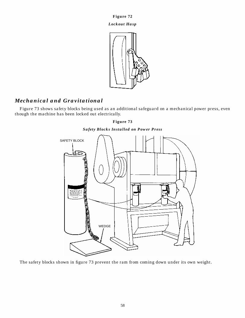
Figure 72
Lockout Hasp
Mechanical and GravitationalFigure 73 shows safety blocks being used as an additional safeguard on a mechanical power press, even
though the machine has been locked out electrically.
Figure 73
Safety Blocks Installed on Power Press
The safety blocks shown in figure 73 prevent the ram from coming down under its own weight.
58
SAFETY BLOCK
WEDGE
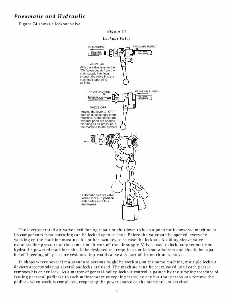
Pneumatic and HydraulicFigure 74 shows a lockout valve.
Figure 74
Lockout Valve
The lever-operated air valve used during repair or shutdown to keep a pneumatic-powered machine orits components from operating can be locked open or shut. Before the valve can be opened, everyoneworking on the machine must use his or her own key to release the lockout. A sliding-sleeve valveexhausts line pressure at the same time it cuts off the air supply. Valves used to lock out pneumatic orhydraulic-powered machines should be designed to accept locks or lockout adapters and should be capa-ble of “bleeding off ’ pressure residues that could cause any part of the machine to move.
In shops where several maintenance persons might be working on the same machine, multiple lockoutdevices accommodating several padlocks are used. The machine can’t be reactivated until each personremoves his or her lock. As a matter of general policy, lockout control is gained by the simple procedure ofissuing personal padlocks to each maintenance or repair person; no one but that person can remove thepadlock when work is completed, reopening the power source on the machine just serviced.
59
FULL LINEPRESSURE
FULL LINEPRESSURE
FULL LINEPRESSURE
PRESSURE BLEEDINGTO ATMOSPHERE
TO MACHINE FROM AIR SUPPLY
FROM MACHINE FROM AIR SUPPLY
VALVE ON
VALVE OFF
With the valve lever in the“ON” position, air from themain supply line flowsthrough the valve into themachine’s operatingair lines.
Moving the lever to “OFF”cuts off all air supply to themachine. At the same time,exhaust ports are opened,bleeding all air pressure inthe machine to atmosphere.
Automatic bleeder valvelocked in “OFF” positionwith padlocks of fouremployees.
Following are the steps of a typical lockout procedure that can be used by maintenance and repaircrews:
1. Alert the operator and supervisor.
2. Identify all sources of residual energy.
3. Before starting work, place padlocks on the switch, lever or valve, locking it in the “off” position,installing tags at such locations to indicate maintenance in progress.
4. Ensure that all power sources are off, and “bleed off ” hydraulic or pneumatic pressure, or “bleedoff ” any electrical current (capacitance), as required, so machine components will not accidentallymove.
5. Test operator controls.
6. After maintenance is completed, all machine safeguards that were removed should be replaced,secured and checked to be sure they are functioning properly.
7. Only after ascertaining that the machine is ready to perform safely should padlocks be removedand the machine cleared for operation.
The maintenance and repair facility in the plant deserves consideration here. Are all the right tools onhand and in good repair? Are lubricating oils and other common supplies readily available and safelystored? Are commonly used machine parts and hardware kept in stock so that the crews are not encour-aged (even obliged) to improvise, at the risk of doing an unsafe repair, or to postpone a repair job? Anddon’t overlook the possibility that maintenance equipment itself may need guarding of some sort. Thesame precaution applies to tools and machines used in the repair shop. Certainly, the maintenance andrepair crew are entitled to the same protection that their service provides to the machine operators in theplant.
60

5Cooperation and Assistance
Safety in the workplace demands cooperation and alertness on everyone’s part. Supervisors, operatorsand other workers who notice hazards in need of safeguarding, or existing systems that need repair orimprovement, should notify the proper authority immediately.
Supervisors have these additional, special responsibilities with regard to safety in the workplace:encouraging safe work habits and correcting unsafe ones; explaining to the workers all the potential haz-ards associated with the machines and processes in the work area; and being responsive to employerrequests for action or information regarding machine hazards. The first-line supervisor plays a pivotalrole in communicating the safety needs of the workers to management and the employer’s safety rulesand policies to the workers.
Sometimes the solution to a machine safeguarding problem may require expertise that is not availablein a given establishment. The readers of this manual are encouraged to find out where help is availableand, when necessary, to request it.
A machine’s manufacturer is often a good place to start when looking for assistance with a safeguard-ing problem. Manufacturers can often supply the necessary literature or advice. Insurance carriers, too,will often make their safety specialists available to the establishments whose assets they insure. Unionsafety specialists can also lend significant assistance.
An important source of information and assistance is the Occupational Safety and Health Division ofthe North Carolina Department of Labor. Within OSHNC are the Bureau of Education, Training andTechnical Assistance and the Bureau of Consultative Services. Both bureaus are separate from the Bureauof Compliance. Neither the Bureau of Education, Training and Technical Assistance nor the Bureau ofConsultative Services issues citations for violations of occupational safety and health standards.Assistance from both bureaus is free. For information on where to write or to telephone for information orassistance, see the inside of the back cover of this publication.
61
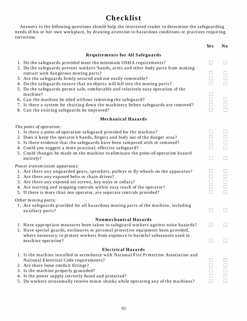
ChecklistAnswers to the following questions should help the interested reader to determine the safeguarding
needs of his or her own workplace, by drawing attention to hazardous conditions or practices requiringcorrection.
Yes No
Requirements for All Safeguards
1. Do the safeguards provided meet the minimum OSHA requirements? ■■ ■■2. Do the safeguards prevent workers’ hands, arms and other body parts from making
contact with dangerous moving parts? ■■ ■■3. Are the safeguards firmly secured and not easily removable? ■■ ■■4. Do the safeguards ensure that no objects will fall into the moving parts? ■■ ■■5. Do the safeguards permit safe, comfortable and relatively easy operation of the
machine? ■■6. Can the machine be oiled without removing the safeguard? ■■ ■■7. Is there a system for shutting down the machinery before safeguards are removed? ■■ ■■8. Can the existing safeguards be improved? ■■ ■■
Mechanical Hazards
The point of operation:1. Is there a point-of-operation safeguard provided for the machine? ■■ ■■2. Does it keep the operator’s hands, fingers and body out of the danger area? ■■ ■■3. Is there evidence that the safeguards have been tampered with or removed? ■■ ■■4. Could you suggest a more practical, effective safeguard? ■■ ■■5. Could changes be made on the machine to eliminate the point-of-operation hazard
entirely? ■■ ■■
Power transmission apparatus:1. Are there any unguarded gears, sprockets, pulleys or fly-wheels on the apparatus? ■■ ■■2. Are there any exposed belts or chain drives? ■■ ■■3. Are there any exposed set screws, key ways or collars? ■■ ■■4. Are starting and stopping controls within easy reach of the operator? ■■ ■■5. If there is more than one operator, are separate controls provided? ■■ ■■
Other moving parts:1. Are safeguards provided for all hazardous moving parts of the machine, including
auxiliary parts? ■■ ■■
Nonmechanical Hazards1. Have appropriate measures been taken to safeguard workers against noise hazards? ■■ ■■2. Have special guards, enclosures or personal protective equipment been provided,
where necessary, to protect workers from exposure to harmful substances used inmachine operation? ■■ ■■
Electrical Hazards1. Is the machine installed in accordance with National Fire Protection Association and
National Electrical Code requirements? ■■ ■■2. Are there loose conduit fittings? ■■ ■■3. Is the machine properly grounded? ■■ ■■4. Is the power supply correctly fused and protected? ■■ ■■5. Do workers occasionally receive minor shocks while operating any of the machines? ■■ ■■
62

Training1. Do operators and maintenance workers have the necessary training in how to use the
safeguards and why? ■■ ■■2. Have operators and maintenance workers been trained in where the safeguards are
located, how they provide protection, and what hazards they protect against? ■■ ■■3. Have operators and maintenance workers been trained in how and under what
circumstances guards can be removed? ■■ ■■4. Have workers been trained in the procedures to follow if they notice guards that are
damaged, missing or inadequate? ■■ ■■
Protective Equipment and Proper Clothing1. Is protective equipment required? ■■ ■■2. If protective equipment is required, is it appropriate for the job, in good condition, kept
clean and sanitary, and stored carefully when not in use? ■■ ■■3. Is the operator dressed safely for the job (that is, no loose-fitting clothing or jewelry)? ■■ ■■
Machinery Maintenance and Repair1. Have maintenance workers received up-to-date instruction on the machinery they
service? ■■ ■■2. Do maintenance workers lock out the machine from its power sources before beginning
repairs? ■■ ■■3. Where several maintenance persons work on the same machine, are multiple lockout
devices used? ■■ ■■4. Do maintenance persons use appropriate and safe equipment in their repair work? ■■ ■■5. Is the maintenance equipment itself properly guarded? ■■ ■■
Other Items to Check1. Are emergency stop buttons, wires or bars provided? ■■ ■■2. Are the emergency stops clearly marked and painted red? ■■ ■■3. Are there warning labels or markings to show hazardous areas? ■■ ■■4. Are the warning labels or markings appropriately identified by yellow, yellow and
black, or orange colors? ■■ ■■
63

The following industry guides are available from the N.C. Department of Labor’s Division ofOccupational Safety and Health:
1#1. A Guide to Safety in Confined Spaces
1#2. A Guide to Procedures of the Safety and Health Review Board of North Carolina
1#3. A Guide to Machine Safeguarding
1#4. A Guide to OSHA in North Carolina
1#5. A Guide for Persons Employed in Cotton Dust Environments
1#6. A Guide to Lead Exposure in the Construction Industry
1#7. A Guide to Bloodborne Pathogens in the Workplace
1#8. A Guide to Voluntary Training and Training Requirements in OSHA Standards
1#9. A Guide to Ergonomics
#10. A Guide to Farm Safety and Health
#11. A Guide to Radio Frequency Hazards With Electric Detonators
#12. A Guide to Forklift Operator Training
#13. A Guide to the Safe Storage of Explosive Materials
#14. A Guide to the OSHA Excavations Standard
#15. A Guide to Developing and Maintaining an Effective Hearing Conservation Program
#17. A Guide to Asbestos for Industry
#18. A Guide to Electrical Safety
#19. A Guide to Occupational Exposure to Wood and Wood Dust
#20. A Guide to Crane Safety
#21. A Guide to School Safety and Health
#23. A Guide to Working With Electricity
#25. A Guide to Personal Protective Equipment
#26. A Guide to Manual Materials Handling and Back Safety
#27. A Guide to the Control of Hazardous Energy (Lockout/Tagout)
#28. A Guide to Eye Wash and Safety Shower Facilities
#29. A Guide to Safety and Health in Feed and Grain Mills
#30. A Guide to Working With Corrosive Substances
#31. A Guide to Formaldehyde
#32. A Guide to Fall Prevention in Industry
#33. A Guide to Office Safety and Health
#34. A Guide to Safety and Health in the Poultry Industry
#35. A Guide to Preventing Heat Stress
#36. A Guide to the Safe Use of Escalators and Elevators
#37. A Guide to Boilers and Pressure Vessels
#38. A Guide to Safe Scaffolding
#39. A Guide to Safety in the Textile Industry
#40. A Guide to Emergency Action Planning
#41. A Guide to OSHA for Small Businesses in North Carolina

Occupational Safety and Health (OSH)Sources of Information
You may call 1-800-NC-LABOR (1-800-625-2267) to reach any division of the N.C. Department of Labor; or visit theNCDOL home page on the World Wide Web, Internet Web site address: http://www.nclabor.com.N.C. Division of Occupational Safety and Health
Mailing Address: Physical Location:1101 Mail Service Center 111 Hillsborough St.Raleigh, NC 27699-1101 (Old Revenue Building, 3rd Floor)Local Telephone: (919) 807-2900 Fax: (919) 807-2856
For information concerning education, training and interpretations of occupational safety and health standards contact:Bureau of Education, Training and Technical Assistance
Mailing Address: Physical Location:1101 Mail Service Center 111 Hillsborough St.Raleigh, NC 27699-1101 (Old Revenue Building, 4th Floor)Telephone: (919) 807-2875 Fax: (919) 807-2876
For information concerning occupational safety and health consultative services and safety awards programs contact:Bureau of Consultative Services
Mailing Address: Physical Location:1101 Mail Service Center 111 Hillsborough St.Raleigh, NC 27699-1101 (Old Revenue Building, 3rd Floor)Telephone: (919) 807-2899 Fax: (919) 807-2902
For information concerning migrant housing inspections and other related activities contact:Agricultural Safety and Health Bureau
Mailing Address: Physical Location:1101 Mail Service Center 111 Hillsborough St.Raleigh, NC 27699-1101 (Old Revenue Building, 2nd Floor)Telephone: (919) 807-2923 Fax: (919) 807-2924
For information concerning occupational safety and health compliance contact:Safety and Health Compliance District Offices
Raleigh District Office (313 Chapanoke Road, Raleigh, NC 27603)Telephone: Safety (919) 662-4597 Fax: (919) 662-4709
Health (919) 662-4711Asheville District Office (204 Charlotte Highway, Suite B, Asheville, NC 28803-8681)Telephone: (828) 299-8232 Fax: (828) 299-8266Charlotte District Office (901 Blairhill Road, Suite 200, Charlotte, NC 28217-1578)Telephone: Safety (704) 342-6163 Fax: (704) 342-5919Winston-Salem District Office (901 Peters Creek Parkway, Winston-Salem, NC 27103-4551)Telephone: Safety (336) 761-2700 Fax: (336) 761-2326
Health (336) 761-2700 Fax: (336) 761-2130Wilmington District Office (1200 N. 23rd St., Suite 205, Wilmington, NC 28405-1824)Telephone: (910) 251-2678 Fax: (910) 251-2654
***To make an OSHA Complaint, OSH Complaint Desk: (919) 807-2796***For statistical information concerning program activities contact:Planning, Statistics and Information Management
Mailing Address: Physical Location:1101 Mail Service Center 111 Hillsborough St.Raleigh, NC 27699-1101 (Old Revenue Building, 2nd Floor)Telephone: (919) 807-2950 Fax: (919) 807-2951
For information about books, periodicals, vertical files, videos, films, audio/slide sets and computer databases contact:N.C. Department of Labor Library
Mailing Address: Physical Location:1101 Mail Service Center 111 Hillsborough St.Raleigh, NC 27699-1101 (Old Revenue Building, 5th Floor)Telephone: (919) 807-2848 Fax: (919) 807-2849
N.C. Department of Labor (Other than OSH)1101 Mail Service CenterRaleigh, NC 27699-1101Telephone: (919) 733-7166 Fax: (919) 733-6197