aapm tg 35, tg 45 safety considerations for linear accelerators
TRANSCRIPT

AAPM Task Group:
TG-35, TG-45
SAMIR LAOUI, Ph.D.

TG-35

Accelerator Safety Hazards
Most common hazards
Incorrect radiation dose
Dose delivered to wrong region
Collision between patient and machine
Incorrect beam energy or modality
Electrical/mechanical problems
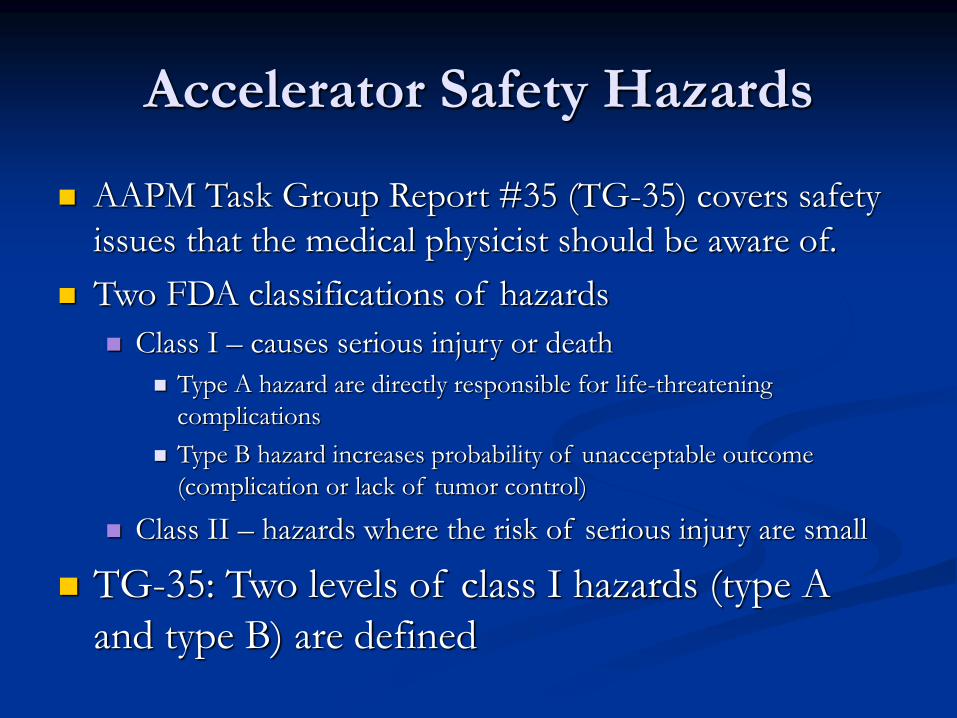
Accelerator Safety Hazards
AAPM Task Group Report #35 (TG-35) covers safety
issues that the medical physicist should be aware of.
Two FDA classifications of hazards
Class I – causes serious injury or death
Type A hazard are directly responsible for life-threatening
complications
Type B hazard increases probability of unacceptable outcome
(complication or lack of tumor control)
Class II – hazards where the risk of serious injury are small
TG-35: Two levels of class I hazards (type A
and type B) are defined

Type of Hazards
Type A hazard: Involves improper delivery of
25% of prescribed dose
The total dose error threshold is on the order of 10-
15 Gy
Radiation overdose caused by a faulty machine
Dose outside the intended radiation field (Critical
Organs)
Patient-machine collision
Incorrect beam energy or modality

Type of Hazards
Type B Hazards:
The total dose error threshold is on the order of 4 Gy
Radiation overdose caused by a faulty machine
Dose outside the intended radiation field
Incorrect energy or mode
Underdose

Accelerator hazards occurrence rate
TG-35: Unable to find published accident
frequencies for radiation therapy devices
Estimation: 40 per day per machine with 15 year
machine lifetime. If 1 type A incident occurs
5 X 10⁻⁶ per patient treatment.
Error rate for faults leading to type B problems
should be set at about 10-4

Procedures in response to
potential hazard It is highly desirable to prepare and adopt a set of procedures for
medical physicists to follow if faced with safety hazards
It is essential to establish a written reporting and documenting
mechanism
In the occurrence of significant un-prescribed radiation exposures
to the patient, the radiation oncologist must take an active primary
role in
The immediate evaluation of the affected patient
Informing the patient of the occurrence and potential for acute and late effects
Informing the other physicians in respective specialties responsible for the
patient’s care
The termination or alteration of the fraction size from the intended regimen of
radiation therapy
Implementing a rigorous timeline for followup patient care to assess the
occurrence of acute and late effects

Reporting of incidents, malfunctions or
machine breakdowns
The most frequent problems can be classified
into three categories 1. Clear breakdowns-no beam
2. Machine suffers frequent interlock interrupts-beam available if
radiation therapy technologist continually resets interlock
3. Machine gives occasional problems that can easily be overridden by
radiation therapy technologist
Seemingly benign faults that are easily reset can
be misleading. They must be reported to physics
Therapist should be trained to identify unusual
situations and change in machine performance
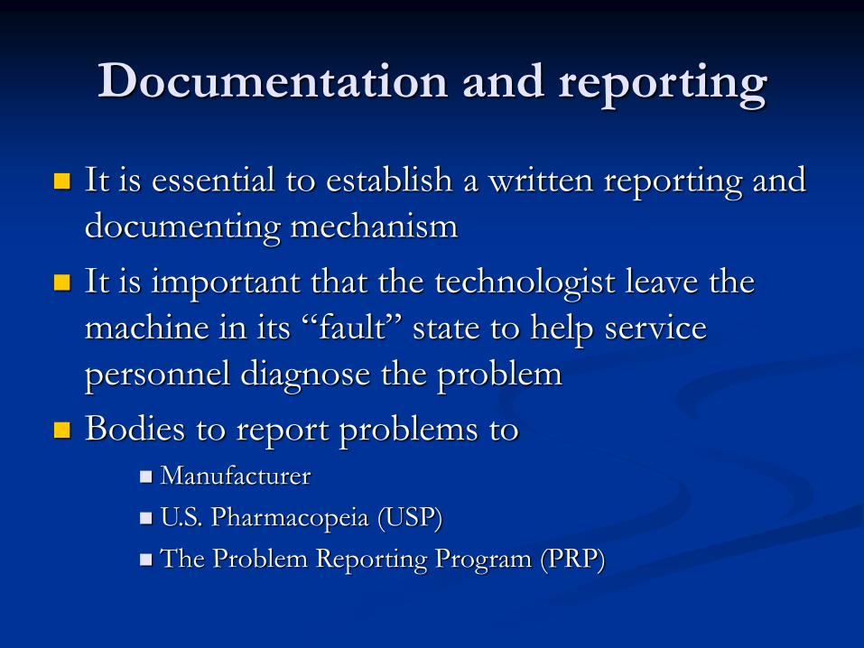
Documentation and reporting
It is essential to establish a written reporting and
documenting mechanism
It is important that the technologist leave the
machine in its “fault” state to help service
personnel diagnose the problem
Bodies to report problems to
Manufacturer
U.S. Pharmacopeia (USP)
The Problem Reporting Program (PRP)


TG-45

PART 1: ADMINISTRATION
Radiation Oncology needs Housing and support equipment
Equipment Selection Acceptance Testing
Commissioning Initial and continuing staff training
Maintenance Quality Assurance (Periodic)
Facilities be staffed at levels that closely follow the guidelines
given in the “Blue Book”
Recommends the radiation oncology physicist be certified in
radiation oncology physics by either the American Board of
Radiology, American Board of Medical Physics, or the Canadian
College of Medical Physics

Medical Physicist
The Physicist is responsible for Acceptance testing
Commissioning
Calibration
Periodic QA
Dosimetry
Treatment planning
Research
the qualified radiation oncology physicist is the
sole individual who can make a decision on the
working conditions of a medical accelerator for
patient treatments
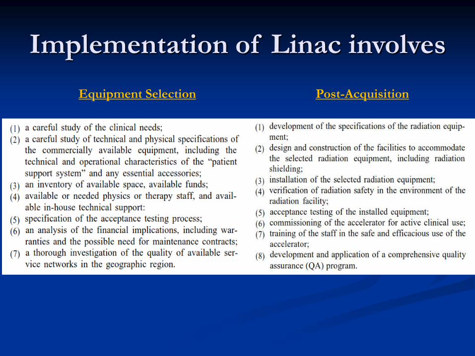
Implementation of Linac involves
Equipment Selection Post-Acquisition

FACILITY PLANNING AND
RADIATION PROTECTION The radiation oncology physicist should be involved in the
design of the facility
Shielding design
Neutron concern at above about 10 MV
Maze (Leads to lighter door)
Door weight and manual access
Room location and orientation
Radiation safety survey
Neutron leakage
Radiation levels outside the room

Radiation Protection Regulation
Regulatory bodies
Linear Accelerators
National Council on Radiation Protection and
Measurements (NCRP)
Individual states (Suggested State Regulations for Control
of Radiation, SSRCR)
Cobalt-60
Nuclear Regulatory Commission (NRC)
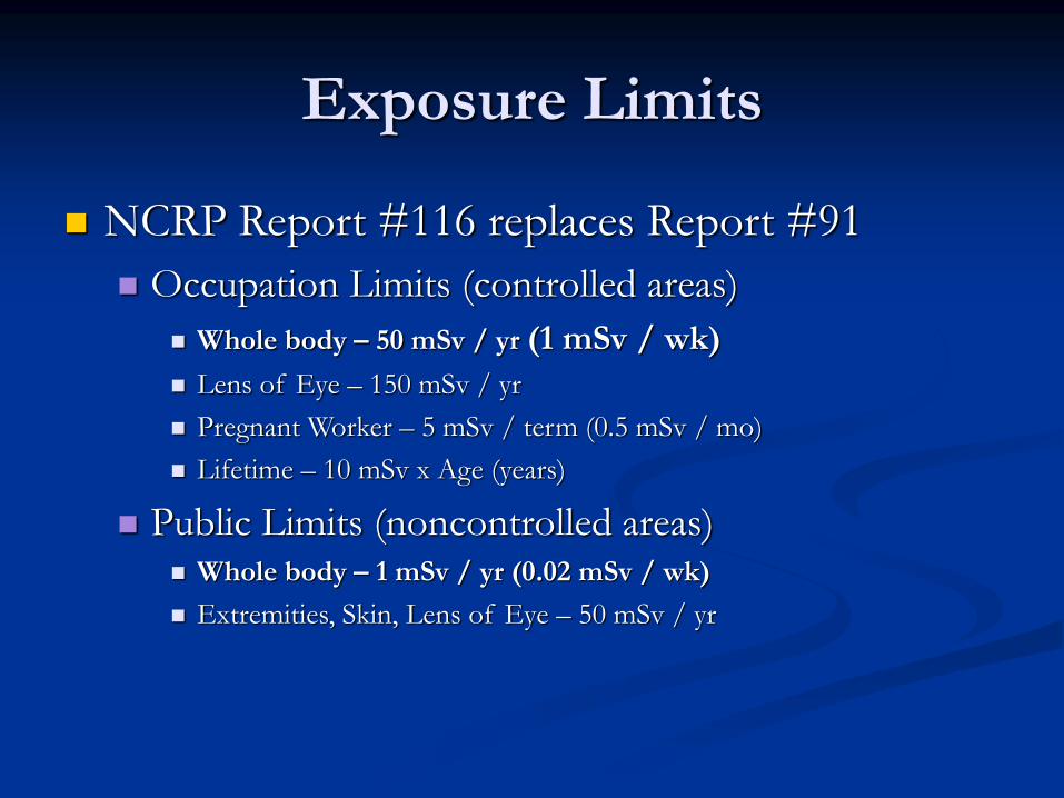
Exposure Limits
NCRP Report #116 replaces Report #91
Occupation Limits (controlled areas)
Whole body – 50 mSv / yr (1 mSv / wk)
Lens of Eye – 150 mSv / yr
Pregnant Worker – 5 mSv / term (0.5 mSv / mo)
Lifetime – 10 mSv x Age (years)
Public Limits (noncontrolled areas) Whole body – 1 mSv / yr (0.02 mSv / wk)
Extremities, Skin, Lens of Eye – 50 mSv / yr

ACCEPTANCE TESTING
Purpose:
Machines meets or exceeds the contractual specifications
Assures the safety of patients and machine operators
Provides critical baseline data for future QA
Checking the treatment area:
During Installation: Warning signs, training, warning lights, audio and
video, door interlocks, emergency power failure
At first delivery of beam: validation of the proper operation of the
door interlock system, Emergency off switches proper operation,
Calibration of the machine output in all modes, Radiation levels outside
the room

ACCEPTANCE TESTING
Mechanical Checks
Alignment of collimator axis and collimator jaws
Collimator axis, light localizer axis, and cross hairs
Light field and radiation field congruence and coincidence
Light field and radiation field symmetry: Collimator jaws symmetry
Light field, radiation field and field readout agreement, and accuracy:
Over full range of collimator and gantry rotations.
Mechanical isocenter location: Sphere containing the
intersection point for all machine orientations.
Radiation isocenter location
With respect to the collimator axis
With respect to couch
With respect to gantry angle
ACCEPTANCE TESTING
Other mechanical system tests Patient support system: Couch verification with and without load
Anti-collision system(s)
Beam Modifiers: electron collimators, Beam stoppers
Console system tests Mode selection
Computer-controlled accelerator software validation: Software updates
must be subjected to an ATP
Readout linearity: Can be done during initial tests cited earlier
Record and verify system: Maintain and record patient’s TX parameters

Radiation beam parameters
Beam output
Calibration TG-21; TG 51
Adjustability and range: cG/MU range
Stability: cG/MU adjustment should be stable
Timer must be accurate and stable
Monitor characteristics
Linearity and end effects: MU linearity
Dose rate accuracy (MU per unit-time)
Dose rate dependence (MU per unit-time settings)
Constancy of output with gantry position

Radiation beam parameters
Flatness
Maximum variation of dose in central 80% of the FWHM of the open field.
X-ray off-axis ratios (“horns”)
Symmetry
Maximum percent deviation of the “left-side” dose from the “right-side” dose at the 80% of the FWHM.
Penumbra
Film is choice because of spatial resolution

Radiation beam parameters
X-ray beam energy
Specified as depth of dmax and/or %dd at 10-cm depth for a
10x10-cm2 field. Example: 18 MV at 3.3 cm. PDD 80% at 10 cm
Electron beam energy
Usually specified at depth of 80% and 50% dose for a 10x10-cm2
field. 12 MeV 80% at 3.8 cm 50% at 5.2 cm

COMMISSIONING
Definition: refers to the process whereby the needed
machine-specific beam data are acquired and
operational procedures are defined
Includes but not limited to:
Beam data acquisition
Entry of beam data into an RTP system and testing of its accuracy
Development of operational procedures
Training of all concerned with the operation of the new accelerator.
Commissioning pre-requisites
Enough time to perform the tests
Using water phantoms and precise equipment

Commissioning of photon beam
One of the most important tasks in commissioning
photon beams is selecting a method for dose calculations
and then collecting the necessary beam data
The accuracy of computerized radiation treatment
planning (RTP) systems for photon beams can be verified
using the data provided by AAPM Task Group 23
The treatment planning system data should be modified
such that the resultant isodose curves match the measured
data

Commissioning of photon beam
Square and rectangular photon beams MU
calculation To calculate the number of MU required to deliver a prescribed absorbed
dose, the following are needed:

Commissioning of photon beam
Wedged photon beams Wedge factor: Ratio of the absorbed dose at specified depth, measured
in the standard geometry with the wedge in place , to the absorbed dose
in the same geometry without the wedge.
Beam-shaping blocks for photons Purpose: conform the basic rectangular field shape to the beam’s eye view
of the target volume
Block transmission factor BTF

Commissioning stationary
electron beams Dose distributions in an electron field depend strongly on the
design and construction of the collimating system- applicators

Dosimetry data for electron
beams The following characteristics must be measured
Output factors
Central axis depth dose curves
Isodose charts
Cross beam profiles
Dosimetry parameters depend strongly upon electron energy that must be
specified for each clinical electron beam
Dose: TG-25
Because of the complexity of the spectrum, there is no single energy parameter
that will fully characterize the electron beam

Commissioning of special procedures
Total and half body photon irradiation Inverse square law may not accurately predict the decrease in beam
intensity at large distances
Change in photon spectrum for large fields (Change in mass abs. coef.)
Large phantoms
Total Skin Electron Irradiation
Additional load placed on linacs by increased dose rate

Intraoperative Radiotherapy
Multidisciplinary procedure: Radiation therapy +
Surgery
Dose delivered at the time on the surgery
Requires special cones
PPD change associated with cones has to be
measured

Stereotactic radiosurgery
Delivers a large dose in a single fraction for the
treatment of intracranial targets
SRS is distinguished from routine TX:
Routine SIM is not done for target volume
determination
3D planning is necessary
More stringent isocenter criteria
Smaller beams are utilized
One fraction

SRS Commissioning
Imaging: Target localization
Treatment planning:
3D dose computation along fined grids (1mm)
Dosimetry: Small fields dose measurement
challenges

QUALITY ASSURANCE
PROGRAMS
Radiation protection of personnel and patients
Safe maintenance and operation of machine
Safety: Emergency situations
Security
Maintenance: the physicist must be aware of what
was done and how it might affect the accelerator’s
operation
Training: Accelerator operation and emergency
procedures
Logistics

QUALITY ASSURANCE
PROGRAMS
Accuracy of dose delivery
An effective quality control program to prevent
treatment errors due to machine malfunction
Maintenance of QA records
Critical parameters should be checked frequently
Refer to AAPM TG-40 for more details