ad-a 141 826c - dtic
TRANSCRIPT

AD-A 141 826C
AFWAL-TR-84-4029
STRENGTH OF BOLTED JOINTS INLAMINATED COMPOSITES
Fu-Kuo ChangRichard A. ScottGeorge S. Springer
Department of Mechanical Engineering and Applited MechanicsThe University of MichiganAnn Arbor. MI 48109
March 1984
Final R~eport for Period June 1983-December 1983
V I DTICELECTEJUN5W
Approved for Public Release; Difstribution Unlimited
fzMATERIALS LABORATORYAIR FORCE WRIZIIT AERtONAUJTICAL LABORATORIESAIR FORCE SYSTENS CONNAND
. .... . ... WR16NT-PATTERSO AF1s. OHIO 4543.3
2 84 06 04 044

NOTICE
When Government drawings, specifications, or other data are usedfor any purpose other than in connection with a definitely related Govern-ment procurement operation, the United States Government thereby incurs noresponsibility nor any obligation whatsoever; and the fact that the Govern-ment may h,•ve formulated, furnished, or in any way supplied the said draw-ings, specifications, or other data, is not to be regarded by implicationor otherwise as in any manner licensing the holder or any other person orcorporation, or conveying any rights or permission to manufacture, use, orsell any patented invention that may in any way be related thereto.
This report has been reviewed by the Office of Public Affairs (ASP/PA)and is releasable to the National Technical Information Service (NTIS). AtNTIS, it will be available to the general public, including foreign nations.
This technical report has been reviewed and is approved for publication.
K.._s11.rPoJ~ect Engin~e eR&Ti_&_CbMechanics and Surface Interactio-. BranchNmvett~lic Materials Division
FOR THE COMMANDER
* I
F.D. tHEARYs ChiefNU.&Otlic 4Tgterils Division
'if your address h4s changed, If you wish to be reove4 from our mail-Ing list, or If the addressee Is no longer employed by your organization pteaseSnotify ANWALIIN, VoPAPS, 01o •,5433 to help us mainGUin a curn'at nailinglist.
Copies of this report should not be returned unless return is requtred by; I / security consideratioms. contractual obligations, or notice on a specific
if

UNCLASSIFIEDSECURITY CLASSIFICATION OF THIS PAGE (*)ýon Does. Entered)
REPORT DOCUMENTATION PAGE READ INSTRUCTONSL REORTNUMBR 1 GOV ACC!.SION NO. S. RECIPIENT'$ CATALOG NUMBERI.~~F NEOG0UOE
AFWAL-TR-84 -4029 14 4v 1 _____ ________
4. TITLE (.dod Soille) S. TYPE OF' REPORT 6 PERIOD COVERED
Final ReportSTRENGTH OF BOLTED JOINTS IN LAMINATED June, 1983-0ecernber 1983COMPOSITES 6. PERFORMING ORG. REPORT NUMBER.
7. AUTNOR(o) S. coN#TxACT 00 GRAN4T S4UMUKR(8
Fu-kuo ChangR~ichard A. Scott F33615-81-c.5050
2_ogeS. Springer______________T. P45oroqmsur ORGANIZATION NAME AND ADDRESS SO- PROGRAM ELEMENT. PROJECT. TASK
)episrtment of Mechanical Engineering and Applied AE O~UI USR
Mechanics, The University of Michigan, FY1457-81-02013Ar-. Arbor, Michigan 48109
11. CONTRaILII4G, OPPICE NAME ANO AOUR92S It. REPORT DATENa~tLcials Laboratory (AFWAL/HLBM) Ratrch 1984Air Force Wright Aeronautical Laboratories(AFSC) is, NUMBER Of PAGESWrigh-z-Patterson, AFB, OH 45433o~, 175 CAS .aJ .
MON.V01140 AQ N NAMC 4 ADORE5(CII~t... 41oa mCx.W.jOt.* 1I-SECURITY 6AS(*am#f t
Unclassified
Is.M bi C L A S CE IN6V~~JA4Q
Approved for public release. diotributiou uali.ms3.ed
i3. ()'STAIMOJY&OU 5ATEMENT aI(#*#A "LAO*"e toi.4 6Akw SO.#U*t saeM
Arthe4 iii wo tt a foric luedtesC m thed taieeorti iMf4ur 4& 0
tacludus evo~ Atps Fi'aro the iacreso didtributia in the laitatea to calciala-ialurewdeare prdco byr ~awa of a propwiod failurwe hyoc'wiio together
wittl cth Yana"ta-Stzn tadtaure criteriou. A computor code siis developod, v.hlchc~ be uued to ealeulkace the manimus load ati4 the moa& of failure of johcagtaslt~viu )awtroaci vitih differenst ply orteatmtions. dif -rent a.3teriat
DD 1013 MLASSIFtIO____

UNCLASSIFIEDSeCURITY CLASSIFICATION OV THIS PAGE(Whan Dots Utort.)
[properties, and different geometries.
Tests were performed, measuring the rail-shear strength and the characteristiclengths for Fiberite T3001l34-C composites. Tests were also conducted, measur-ing the failure strengths and failure modes of Fiberite T300/1034-C laminatescontaining a pin-loaded hole or two pin-loaded holes in parallel or in series.
Comparisons were made between the data and the results of the model. Goodagreement was found between the analytical and the experimental results.
Using the computer code, parametric studies were performed, illustrating theprocedures which can be used to size composites containing pin-loaded holes.\
"aV
/w
' '• LtrNCL SSI1FI1 El

FOREWORD
This report was prepared by Fu-Kuo Chang, Richard A. Scott, andGeorge S. Springer, Department of Mechanical Engineering and AppliedMechanics, The University of Michigan for the Mechanics and SurfaceInteractions Branch (AFWAL/MLBM), Nonmetallic Materials Division,Materials Laboratory, Air Force Wright Aeronautical Laboratories,Wright-Patterson AFB, Ohio. The work was performed under Contract Num-ber F 336lS81-C5050, Project number FY1457-81-02013.
This report covers work accomplished during the period June 1983-
December 1983.
I t
ii
t. OlutI •1?1
•! |T"
'Jil
L ... .. ... 0

TABLE OF CONTENTS
SECTION Page-
I. INTRODUCTIO71 1
I I . PROBLE), STATEMENT 3
III. STRESS ANALYSIS 7
3.1 Governing Equation 83.2 Boundary Conditions: Single Hole and
Two Holes in Parallel 133.3 Boundary Conditions: Two Holes in Series 173.4 Finite Element Analysis 20
3.4.1. Method of Solution, Single Hole andTwo Holes in Parallel 25
3.4.2. Method of Solution; Two Holesin Series 26
IV. PREDICTION OF FAILURE 34
4.1 Failure Criterion 344.2 Failure Hypothesis---Characteristic Curve 354.3 Solution Procedure 38
V. NUMERICAL SOLUTION 41
V1. EXPERIMENT 47
6.1 Measurement Procedure for the LaminateShear Strength S 47
6.2 Measurement Procedure for6 The Characteristic Length R 496.3 Measurement Procedure for
The Characteriutic Length R 506.4 Strength of Mechanically raitened
Composite Joints 536.5 Specimen Preparation 54
.
V

TABLE OF CONTENTS (Coatcluded)
VII. MEASUREMENT OF S, Rt, AND Rc 58
7.1 Rail Shear Strength S 587.2 Characteristic Length Rt 597.3 Characteristic Length R 64
VIII. EXPERIMENTAL VALIDATION OF THE MODEL 66
IX. DESIGN CONSIDERATIONS 79
9.1 Interaction Coefficients 809.2 Numerical Values of Interaction
Coefficients 829.3 Laminates With One or Two Holes 889.4 Laminates With Multiple Holes 929.5 Failure Mode 97
X. SUMMARY AND CONCLUSIONS 101
REFERENCES 103
APPENDI CES
A The Transformed Reduced Stiffness Matrix p 1078 The Coordinate Transformation Matrix Ti.J IU9C The Hinite Element Mesh Generator 110D Shape Function Used in the Finite Element Code 113E Listing of a Sample of Input-Output of the 115
Computer Code 114F Suftury of Data for Calculating S. Rt, 129G Summary of Data for Loaded Holes 139
I
vi!i"

LIST OF ILLUSTRATIONS
Figure page
1. Descriptions of the Problem. Top: Single HoleModel; Middle: Two Holes in Series; Bottom:Two Holes in Parallel. 4
2. Illustration of the Three Basic Failure Modes 6
3. Elastic Laminates with One Hole (Left), TwoHoles in Parallel (Middle), and Two Holes inSeries (Right). 9
4. Configurations Used in the Finite ElementCalculations. 14
5. Grid Used in the Finite Element Analysis for aSingle Hole. Right Hand Figure is an EnlargedView of the Grid Around the Hole. 21
6. Grid Used in the Finite Element Analysis forTwo Holes in Parallel. Right Hand Figure is anEnlarged View of the Grid Around One ofthe Holes. 22
7. Grid Used in the Finite Element Analysis forTwo Holes in Series. Right Hand Figure is anEnlarged View of the Grid Around Hole. 23
8. Illustrotion of the Local Coordinate System x1and x2 along the Contact Sjrfaces 27
9. illustration of the Reversal of the NormalStresses When the Assumed Contact Angles 9a.and 0 are Greater than the Actual Contact-Angles L(Left). No Stress Reversal Occurs forthe Actual Contact Angles 0 and aL (Right). 32
10. Variation of the Contact Angle With the widthRatio for a Laminate Containing Two Holesir. Series. 33
)I. Description of the Characteristic Curve. 36
12. Location of railure 'eal) Along theCharacteristic Curve. 40
13. Stress oa Along x.-axis in an Iso t ropicSInfinite Plate Co~taining a Circular Hole.
SjComparison of Present Results with Theoretic:.lResults Given by Tiaoshenko (38). ParametersUsed in Numerical Calculations: o-2.37 kei.D.2a-0.3 in. W/D.*1, C/.8. L/Du.28. 43
/ vli

LIST OF ILLUSTRATIONS (Cont'd)
14. Stress 02 Along the x -axis in an IsotropicPlate of Finite Width Containing a Loaded Hole.Comparison of the Present Results With theTheoretical Results Given by De Jong (243.Parameters Used in the Numerical Calculations:D=O.3 in, W/D-5, E/D=4, L/D-14. 45
15. Stress o Along the x -axis in an OrthotropicFinite Piate (0/903 containing a Circular Hole.Comparison of the P?esent Results With theTheoreticla Results Obtained by Nuismer andWhitney (34]. Parameters Used in the NumericalCalculations: Materi9l: Graphite/EpojyT300/5208, j 1 =21.4x1O ksi, E =l.6xI0 ksi,G j=0.77x10 ksi, ,p= 0 . 2 9, o=i.3 ksi,Du in, W/D-3, E/D- , LE/D=14 46
16. Schematic of Rail Shear Test Fixture. 48
17. Fixture Used in Testing Loaded Holes (Base PlateGeometry Given in Figure 18 and Table 2). 51
1B. Base Plates Configurations (See Figure 17)Plate Thickness 1/4 in. The Dimensions G, D,and E are Given in Table 2. 55
19. Variation in Rail Shear Strength with theVolume Fraction of 0 Degree Plies of Cross PlyLaminates. o Data. - Fit to Data. S50-50% Volume Fraction of 0 Degree Plies *19400 psi 61
20. Characteristic Length in Tension R as Functionof Hole Diameter. Width Ratio. i•dPly,Orientation. 62
21. Variation of Characteristic Length in Tension RtWith Hole Diameter. Data are for the LaminateConfigurations Given iW Figure ZC. 63
22. Bearing Strengths of Fiberite T300/1034-CLaminates Containing a Single Loaded Hole.Comparisons Between the Data and the Results ofthe Model. The Failure Modes Calculated by theModel are the Same as Those of the Data UnlessIndicated by a Letter in Parentheses next tothe Data Point. 70
Vt

LIST OF ILLUSTRATIONS (Con'd)
23. Bearing Strengths of Fiberite T300/1034-C
Laminates Containing a Single Loaded Hole.Comparisons Between the Data and the Results ofthe Modle. The Failure Modes Calculated by theModle are the Same as Those of the Data UnlessIndicated by a Letter in Parentheses next tothe Data Point. 71
24. Bearing Strengths of Fiberite T300/1034-CLaminates Containing a Single Loaded Hole.Comparisons Between the Data and the Results ofthe Model. The Failure Modes Calculated by theModel are the Same as Those of the Data UnlessIndicated by a Letter in Parentheses next tothe Data Point. 72
25. Bearing Strengths of Fiberite T300/1034-CLaminates Containing Two Loaded Holes in Parallel.Comparisons Between the Data and the Results ofthe Model. The Failure Modes Calculated by theModel are the Same as Those of the Data UnlessIndicated by a Letter in Parentheses next tothe Data Point. 73
26. Bearing Strengths e:.f Fiberite T300/1034-CLaminates Containing Two Loaded Holes in Parallel.Comparisons Between the Data and the Results ofthe Moeel. The Failure Modes Calculated by thethe Model are the Same as Those of the Data Unlessindicated by a Letteb- in Parentheses next tothe Data Point. 74
27. Bearing Strengths of Fiberite T300/1034-CLaminates Containing Two Loaded Holes in Series.Comparisons Between the data and the Results of
V the Model. The Failure Modes Calculated by theModel are the Same as Those of the Data Unlesuindicated by a Letter in Parentheses next tot• the Data Point. 75
I *28. Bearing Strengths of Fiberite T300/1034-C
Laminates Containing Two Loaded Holes in Series.Comparisons Between the Data and the Results ofthe Model. The Failure Modes Calculated by theModel are the Same as Those of the Data UnlessIndicated by a Letter in Parentheses next to' =the Data Point. 76

LIST OF ILLUSTRATIONS (Cont'd)
29. Bearing Strengths of Fibtrite T300/1034-CLaminates Containing Two Loaded Holes in Series.Comparisons Between the Data and the Results ofthe Model. The Failure Modes Calculated by theModel are the Same as Those of the Data. 77
30. Interaction Coefficient for Two Holes inParallel. Results of the Model. 84
31. Interaction Coefficient for Two Holes in Series.Results of the Model. 85
32. Edge Interaction Coefficient. Results ofthe Model. 86
33. Side Interaction Coefficient. Results of theModel. 87
34. Description of the Problem Used in DesigningLaminates With a) Single Pin-Loaded Hole, b)Two Pin-Loaded Holes in Parallel, c) Two Pin-Loaded Holes in Series. 89
35. Failure Load as a Function of Edo- Ratio forLaminates Containing a Single Pik.-Loaded Holes.Results of the Model. 90
36. Failure Load (Top) and Failure !,oad Per Unitweight (Bottom) of Laminates Containing a SinglePin-Loaded Hole , Two Pin-Loaded Holes inParallel and Two Pin-Loaded Holes in Series.Results of the Model. 93
37. Geometry of Single Row of Holes (Top) and TwoRows of Holes (Bottom). 94
38. Failure Load (Top) and Failure Load Per UnitWeiqht (Bottom) of Laminates Containing One Row(Le:t) and Two Rows (Right) of Pin-Loaded Holes.Results of the Moýil. 99
39. Failure Modes of Laminates Containing a SingleRow (Let) and Two Rows (Right) of Pin-LoodedHoles. Results of the Model.
40. Geometry of an Element Used in the Finite Eleme:v'Calculations: Left: Element in the x-x,Coordinate System. Right: element (Maiteoelement) in the Local (r-s) Coordinate System.x. is the Coordinate of Node * in the iDi ection, q• is the Displacement of Nodea in the i Dvection and 4r *s ) are theCoordinates of Node a in thg rrs CoordinateSystem. iol,2. cia.2.3. or 4. 114

LIST OF TABLES
Table Page
1. Input Parameters Required by Computer Code andthe Output Provided by Code. 42
2. Dimensions of the Base Plates in Figures 17and 18 . All Units in Inches. 56
3. Properties of Fibecite T300/1034-C Graphite-Epoxy Composite 57
4. The Characteristic Length in Compression Rc forFiberite T300/1034-C. Data Obtained forD-0.25 in, W-2.0 in , Lv7.0 in, E1.25 in. 65
5. Approximate Differences Between the Experimental(P and Calculated (P_) Failure Loads ofLaminates Containing S Single Loaded Hole.The Numbers Indicate Maximum Differences (inPercent! for the Indicated Hole Diameters andPly Orientations 78
6. Rail Shear Strength S of Cross Ply [0,190]laminates. (411 Length Units in inches) 130
7. Chnracteristic Length iaTension Rt-Ply Orientation ((0/t45/90) 31]S 131
8. Characteristic Length in Tension Rt.Ply orientation (O(•45)3/90-3S 132
9. Characteristic Length in Tension Rt.Ply Orientation (0(:45)2/90515 133
10. Characteristic Length in Tension Rt.Ply Orientation (07t45/9071, 134
II. Characteristic Length in Tepsion RtePly Orientation [(g10 /:60/:30)2 ]s 135
12. Characteristic Len th in Tension R t 136Ply Orientation (1 /90)(| 1
13. Characteristic Length in Tension Rt.Ply Orientation ((:45)] 13?
14. Characteristic Length in Compression Rc 138
15. DaMta and Calculated Values for JointsContaining a Single Hole. ((0/:45/90)31, 140
16. Data and Calculated Values for joints
Si'
£:
LIST OF TABLES (Cont'd)
Containing a Single Hole. [0/(±45) 3 /90 3 1s 142
17. Data and Calculated Values for JointsContaining a Single Hole. [0/(±45)2/905)s 143
18. Data and Calculated Values for JointsContaining a Single Hole. [0/±45/907]s 144
19. Data and Calculated Values for JointsContaining a Single Hole. P(902/±60/±30)21s 145
20. Data and Calculated Values for JointsContaining a Single Hole. [(0/90) 6] 147
21. Data and Calculated Values for JointsContaining a Single Hole. ((±45)61s 149
22. Data and Calculated Values for JointsContaining Two Holes in Parallel.[(0/±45/90)31s 151
23. Data and Calculated Values for JointsContaining Two Holes in Parallel.C[(902/±60/±30)2]s 152
24. Data and Calculated Values for JointsContaining Two Holes in Parallel. ((0/90)6]s 153
25. Data and Calculated Values for JointsContaining Two Holes in Parallel. [(±45) 154
26. Data and Calculated Values for JointsContaining Two Holes in Series. [(0/±45/90)3]s 155
27. Data and Calculated Values for JointsContaining Two Holes in Series.[( 9 02/±60/±30)2]s 156
28. Data and Calculated Values fov JointsContaining Two Holes in Series. [(0/90)6 157
29. Data and Calculated Values for JointsContaining Two Holes in Series. (t45)61s 156
xii

LIST OF SYMBOLS
A Total Surface Area of Laminate
AL Stress Prescribed Area
AF Stress Free Area
AR Displacement Prescribed Area
ARS Surface Along Symmetric Axis
ARC Total Contact Surfaces Inside Upper and Lower
Holes
A Surface Area of an Element g on Which SurfaceLg Tractions are Applied
B Bearing Stress
D Diameter of Hole
E Edge Distance
Ei "•qtic ModuliijklEmn Reduced Elastic Moduli
e Failure Indicator (e<1 Non-Failure, eal Failure)
eo Maximum Value of e on Characteristic Curve
f Fraction of By-Pass Load over Total Load
Assembled Load Vector
GH Distance Between Two Holes in Parallel
Gv Distance Between Two Holes in Series
9E Edge Distance Coefficient
9 H Parallel Hole Interaction Coefiicient
9S Side Interaction Coefficient
gV Series Hole Interaction Coefficient
H Thickness of Laminate
hp Thickness of p-th Ply
iiii~t I
'r: 4

LIST OF SYMBOLS (Cont'd)
Kg.ika Stiffness Matrix of g-th Element
K Assembled Stiffness Matrix
L Plate Length
L Total Length of Steel Pin
M Number of Element
N Number of Plies in Laminate
N Number of Holes in a Row
N Shape Function
nj Unit Vector Normal to Surface
P Applied Load
P Load Carried by Pin (Pins)
P By-pass Load
Failure Load of Laminate Containing One Row ofHoles
Failure Load of Laminate Containing T'io Row ofHoles
SPc CFailure Load of Laminate (width W) ContainingSingle Hole at the Center of Laminate
PG Failure Load of Laminate (width 2W) ContainingTwo Holes Separated by Distance GH (61 2 W)
P H Failure Load of Laminate (width 2W) ContainingTwo Holes Separated by Distance W
P Failure Load of Laminate (width W) ContainingSingle Hole at Distance F from the Edge
Failure Load of Laminate NWidth.W) ContainingS, Two Holes; One Located at Distance E from the
Edge, the Other Located at the Center of theLaminate
*1 Failure Load of Laminate (Width W) ContainingTwo Holes in Series
iPH Maximum Failure Load of a Laminate ContainingPin-Loaded Holes
i1 P Failure Load Pe Unit Weight
U' 0v
7-

LIST OF SYMBOLS (Cont'd)
P• M Maximum Failure Load Per Unit Weight of aLaminate Containing Pin-Loaded !-oles
P Failure Load Per Unit Weight of a Laminater] Containing one Row of Holes
P r2 Failure Load Per Unit Weight of a LaminateContaining Two Rows of Holes
P_ Failure Load Carried by Second ThroughN 0Next to Last Pins in Laminate Containing One Row
or Two Rows of Holes
Psid Failure Load Carried by the Two Pins Next tothe Sides in a Laminate Containing One Row or TwoRows of Holes
Q The Distance Between the Side and the Adjacent
Hole
QP Transformed Reduced Stiffness Matrix of p-thPly
q• Nodal Displacement
Radial Distance
rc Radial Distance to the Characteristic Curve
R t Characteristic Length for Tension
R c Charecteristic Length for Compression
S Larainate Shear Strength
S Laminatc Shear Strength of [0/90) Laminate50 With 50 Percent Volume Fraction of 0 Degree
* j 7ibers.
5 Total Surface Area of fTo-DimensionalI, L~ami !aa~e
S! sg Area of glament g
Surface Traction Component
6T Surface Traction Cumponent on ALl Surface
Surface Trac.ion Component on AL2 Surface
T Normal Stress on Hole $,-rtace at 0 * 0
jui Displacements
1
AV
.7 77=

LIST OF SYMBOLS (Cont'd)
ui Arbitrary Displacement Functions
V0 Total Volume of Laminate
Vg Volume of Element g
W Width of Plate
w The Combined Weight of Laminate and Pins
w The Weight of the Laminate
wi ws The Weight of the Pins
X xt Ply Tensile Strength
.Xc CPly Compressive Strength
x Coordinate Along Fiber Direction in Each Ply
xi Coordinate Perpendicular tothe Loading
Sx 2 Coordinate Opposed to the Loading Direction and2 Perpendicular to the x Direction
x 3 Coordinate Perpendicular to the x1 and x 2 Axes
y Coordinate Perpendicular to the Fiber Directionin Each Ply
rL Boundary Curve of Hole on Which SurfaceFL Traction is Applied
Fcg Boundary of Element Along Contact Regionsr Boundary Curve of Element g on WhichLg Surface Traction is Applied
Strain Components in xl-X Coordinate System
1 n Angle Measured Counterclockwise from xl-axis
Of Angle at which Failure OccursfThe Contact Angle on the Upper Hole
80 The Contact Angle on the Lower Hole
Pc Density of the Laminate
pi Density of the pin
S•oVolume Fraction of Plies With 0 Degree FibersS0
: XVi,i 4 S:

LIST OF SYMBOLS (Concluded)
oij Stress Components in the xl-X2 Coordinate System
a "ao, Stress Components in the x-y Coordinate System
xvii
.!I*'" "::",. •" . L.• ::•,•."::;..- ., ,. '. . *,,.o <.' ;f • • -l ••? '.- i@ , ..

-i- -i -•' "
I'
SECTION I
I NTRODUCTI ON
Among the major advantages of laminated composite
structures over conventional metal structures are their
comparatively high strength to weight and stiffness to
weight ratios. As a result, fiber reinforced composite
materials have been gaining wide application in aircraft and
spacecraft construction. These applications require joining
composites either to composites or to metals. Most
commonly, joints are formed by using mechanical fasteners.
Therefore, suitable methods must be found to determine the
failure strengths and failure modes of mechanically-fastened
joints. A knowledge of the failure strength and failure
modes would help in selecting the appropriate size joint in
a given application.
Owing to the significance of the problem, several
investigators have developed analytical procedures for
calculating the strength of bolted joints in composite
: materials. Among the recent studies are those of Waszczak
and Cruse (Reference 1), Oplinger and Gandhi (References 2 & 3), Agarwal
(Reference 4), Soni (Reference 5), Garbo and Oyonowski (Reference 6).
York, Wilson. and Pipes (References 7 & 8),and Collings (9). The
results of these investiqations apply only to joints containing a
single hole, and, with the exception of Agarwal's method, none of the
previous methods can predict the mode of failure. Furthermore, as will be
discussed in Section VIII, the previous methods provide conservative
results and underestiiate the failure strength, often by as much as 50
percent.

2
The first objective of the investigation was,
therefore, to develop a method which a) can be used to
estimate both the failure strength and the failure mode of
pin-loaded holes in composites, b) applies to laminates
containing either one pin-loaded hole or two pin-loaded
holes in parallel, or two pin-loaded holes in series, c)
provide results with better accuracy than the existing
analytical methods and, d) can be used in the design of
mechanically-fastened composite joints. The second
objective was to develop a "user friendly" computer code
which can be used to predict the failure strength and
failure mode of loaded holes (joincs) involving laminates
with different ply orientations, different material
properties, and different configurations-- including
different hole sizes, hole positions, and joint thicknesses.
The third objective was to generate data which can be used
to assess the accuracies of analytical methods,
The analytical model and the corresponding numericalmethod of solution are presented in Sectiohs II-VI. The
experimental apparatus and procedures are given in Section
VZX. The data, and comparisons between the analytical and
experimental results are presented in Section V!Zi. "he use
of the model in the design of joints is described in Section
'IX.
a • iJ.I
SECTION II
PROBLEM STATEMENT
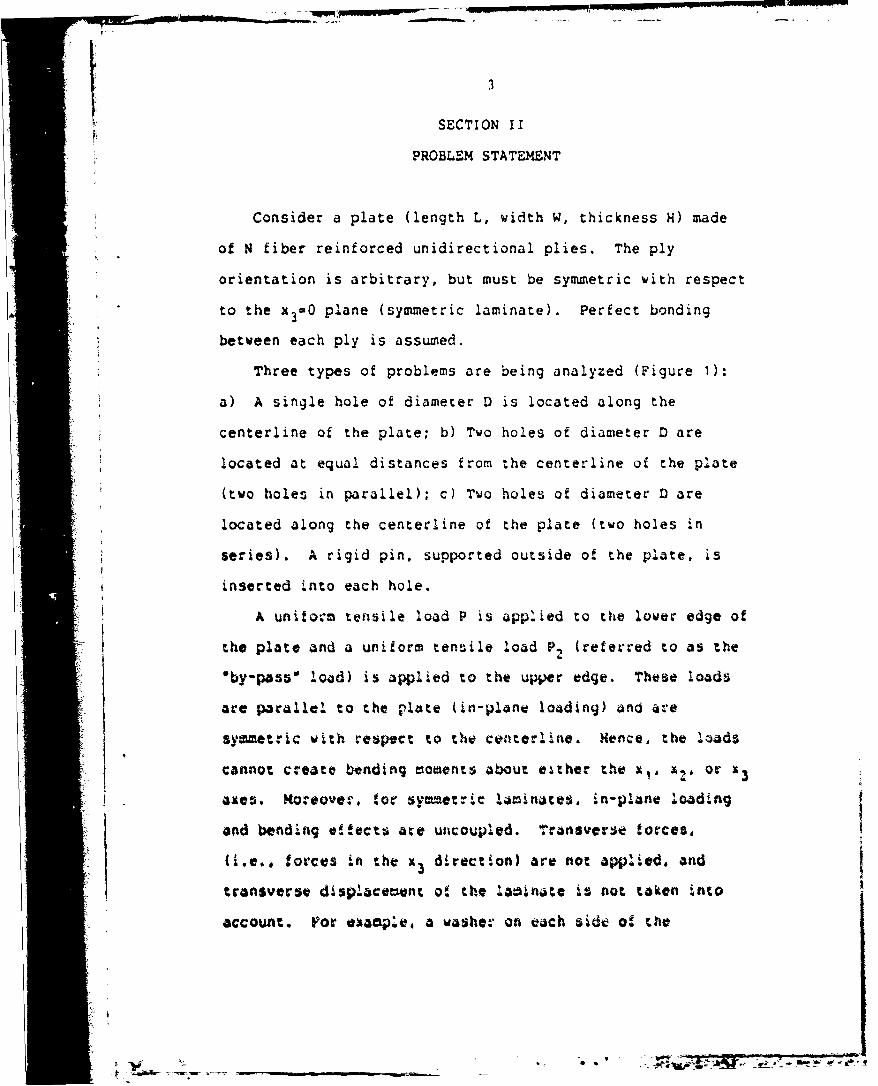
Consider a plate (length L, width W, thickness H) made
of N fiber reinforced unidirectional plies. The ply
orientation is arbitrary, but must be symmetric with respect
to the x 3 -0 plane (symmetric laminate). Perfect bonding
between each ply is assumed.
Three types of problems are being analyzed (Figure 1):
a) A single hole of diameter D is located along the
centerline of the plate; b) Two holes of diameter D are
located at equal distances from the centerline of the plate
(two holes in parallel); c) Two holes of diameter D are
located along the centerline of the plate (two holes in
series). A rigid pin, supported outside of the plate, is
inserted into each hole.
A unito'm tensile load P is applied to the lower edge of
the plate and a uniform tensile load P, (referred to as the
"by-pass' load) is applied to the upper edge. These loads
are parallel to the plate (in-plane loading) and are
symmetric with respoct to the centerline. Hence, the loads
cannot create bending moments about either the x•, XV or I3
axes. Moreover., !or symmetric i.miates, in-plane loading
and bending e!!ects are uncoupled. Transverse forces.
(i.e.. forces in the x, direction) are not applied. and
transverse displacement o! the la.inate .s not taken into
account. For exhaople, a washe, on each aide o! the
-7 W17-

p pp2 p2
X2ttt tX
p2 pl
L
w H
p pfigure 1. De-Scriptions of the Problqtm. Top: Single Role
Model: Middle: TVo HoleS in Series; Bottom:'No Holes in parallel.

I,
laminate, supported by a lightly-tightened ("finger-tight*)
bolt in the hole, would ensure that there is no transverse
displacement, and that the condition of two dimensionality
is satisfied 110).
It is desired to find
1) the maximum (failure) load (P) that can be applied
before the joint fails, and
2) the mode of failure.
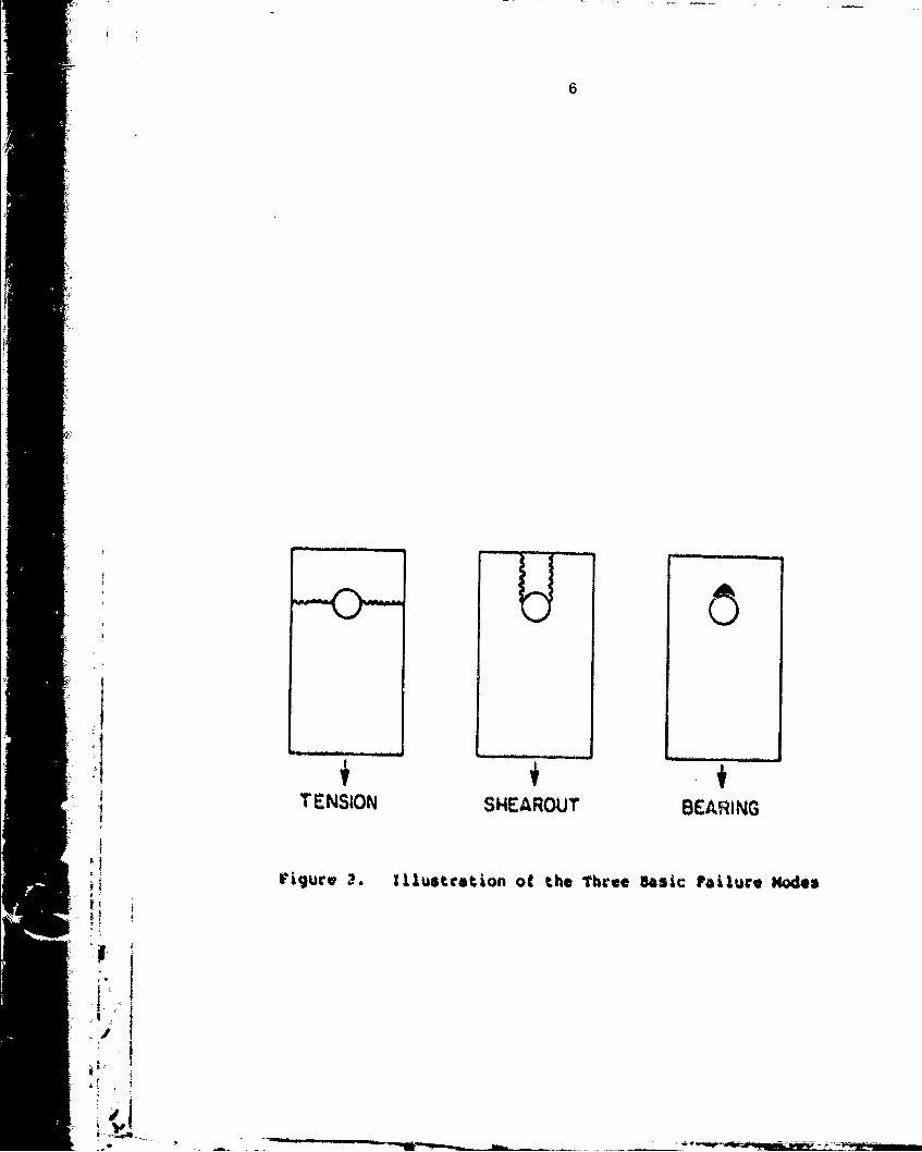
Point 2 refers to the fact that, according to
experimental evidence, mechanically-fastened joints under
tensile loads generally fail in three basic modes, referred
to as tension mode, shear-out mode, and bearing mode. The
type of damage resulting from each of these modes is
illustrated in Figure 2. The objective, listed in point 2
"above, is to determine which of these modes will most be
responsible for the failure.
The calculation proceeds in three steps. For a given
geometry and load •
1) the stress and strain distributions around the hole arecalculated,
2) the maximum (failure) load is predicted,
3) the mode of failure is determined.
The details of these steps are presented in Sections IIN andIV.
ii
e- •
6
4 TENSION SHEAROUT BEARING
Figure I. Illustration of the Three Basic railure Modes
i F
* I•
7
SECTION III
STRESS ANALYSIS
The calculation of Stresses raises the issue of whether
a two or three dimensional stress analysis is required. If
tests were to show that the stacking sequence did not affect
the failure strength and the failure mode, then a two
dimensional stress analysis would suffice. Existing
experimental evidence indicates that the stacking sequence
is important only when a) the laminate is narrow (and edge
effects are not negligible [11]). or b) the laminate is
unrestrained laterally (12]. However, even when the
stacking sequence affects the results, it seems to affect
the failure strength by only 10 percent to 20 percent
[11-15]. Furthermore, the failure strength and the failure
mode seem unaffected by the stacking sequence when there is
a slight lateral constraint on the laminate, such as
provided by lightly tightened (finger-tight) bolts
i i (c,0.6.,7].
For these reasons, a two dimensional stress analysis was
chosen for the present work. As will be demonst:ated in
Section ViIl. this analysis provides a useful estimate of
the failure strength and the failure =We of loaded holes.
in addition to beiag reasonably accurate, the two
dimensional analysis adopted here also provides a simple and
inexpensive means for calculating failure strengtht and
failure modes. making it an attractive design aid.
/

/I I
3.1) Governing Equations
The stresses in the laminate are calculated on the bases
of theory of anisotropic elasticity and classical-lamination
plate theory. Accordingly, in the analysis, planes are
taken to remain planes, the strain across the thickness ;s
taken to be constant ([ij'f(xlx2)], and only plane stresses
are considered (c13ao23=033a0). Under these conditions, in
the absence of body forces, the condition of force
equilibriui can be expressed as E18]
(1)
Bo2 1/ax 1*ao 22 /0-x 2 0
In index notation eq. (t) becomes
c 0 (2)
oij is the stress component in the plane nor-=! to the
"x ax is and is in the xj direction. The subscripts i anid j
may have the values of I or 2. Now consider an elastic
laminate o! volume V0 containing a single pin-loaded hole or
two pin-loaded holes, as shown in Figure 3. Loads are
applied over the surface area AL. The displacements along
the surface area a are restricted in a stnner described
st-t'sequently. The surface area is tree of applied
stress.
* *i

C~
0L
o E-
a)) C
CL0
< Dc
a)a
.- rl 0'0
< N)
CIA

To
The total surface area is
A- AL AR +AF(3
Let us denote by Zi any arbitrary displacement inside
the body. *~is a test function. The only requirement is
that u.be continuous and differentiable. In addition,
along the A R surface, the components of 5i normal to the
surface must be zero. By multiplying eq.(2) by 5.and by
taking the volume integral of the resulting expression, we
obtaiin
ifff 0 03ij,j Ui~ :
By employing tý'e identity
~ 5.*(O. *j o* (5)
'I and by utilizing Gauss' theorem, eq. (4) may be- written as
nj01 dA O- o dVu 0
where n. is the unit vector normal to the srface. By
utilihzing tiq.(3). eq.(6) can be express.eda
o nudA * (i o.ijai, d.CA oj *Up.j dA
* Iff~ o uij(7)
Hi ijU~

On the free surface AF the stresses are zero. This
condition gives
HAF aij nj U1 d " 0 (8)
The forces per unit area (called surface traction) at each
point of the surface area AL are (182
T.- a.. n. (9)i1)
Equations (7)-(9) yield
ffLT ii dA M ffAR oijnidA fjfv oijij dV (10)
The stress is related to the displacement through the stress
-strain relationship, which for an elastic body is [183
°ij " -ijkl Ckl •
The subscripts k and I may take on the values of I or 2. in
order to 7educe the analysis from three dimensiont to tvo
dimensions, the reduced modulus 9 is introduced
I a j(hP/i4) OP12
t here hP is the thickness of the p-th ply, and 011P is the
transformed reduced stiffn•ss matriu for the P-th ply [193
.-- .a..'-'a'.$r-~Pe*. - ~-;, - ';A ':. W
L _ _ _ _ _ _ _ _~- -

12
(Appendix A). The subscripts i,j,k, and 1 are related to m
and n as follows
i-j-1 M r-1 k=l-1 n-1
i-j-2 - m-2 k-1=2 nw2
i#j - m-3 kol n=3 (13)
Note that this reduced modulus is a constant and is
independent of the thickness of the laminate. The strains
are related to the displacements ul by the expression
ckl - (1/2)( auk/axl + aul/axk ) (14)
By combining eqs (10)-(14) we obtain
fIfV EijklUijuk,1 dV .ffA Ti.i dA fAR oijnjuidA (15)
Since the problem is treated as two dimensional, the
"displacements and, consequently the strains are constant
I: across the laminate. Hence the stresses, as defined by
I eq.(11), are also constant across the laminate. However,
the on axis stresses in each ply vary froi ply-to-ply, and
are given by
op
Po' (TIE.lT 62 (16)
aPXy Y12
.. 777" ---

13
where the subscripts x and y represent the directions
parallel and normal to the fibers, respectively. The matrix
[TI is the coordinate transformation matrix given in
Appendix B.
3.2), Boundary Conditions; Single Hole and Two Holes in
Parallel
For problems involving a single hole and two holes in
parallel, it is assumed that a portion of the surface of
each hole is subjected to a surface traction Ti (Figure 4).
The parameter T. is related to the applied load. Thei
spatial distribution of Ti* depends on the magnitude of the
applied load, on the material properties, and on the
geometry in a complex manner. It is extremely difficult to
I: determine the exact distribution of Ti* inside the hole
[20-22]. To overcome this difficulty, a cosine normal load
distribution was assumed. With this approximation, a force
balance in the x2direction gives
'T 2
Pu P2 + H f (D/2)T cos 2 e do (17)
where T2 is the normal stress at the hole surface at e90.
At any arbitrary angle 6 (-v/25 eOw/2), the stress normal to
the surface is
T Tx ni cose (18)
................-x-.~-

14
_L ~U)-j
00 cr.
V) C)
0 C0
0
_ -IA_ a6
-~ W j (A

15
Eq(17) and (18) give
-4 C((P-P2 )/7DH) ni cose (19)
where P2 is the by-pass load which is a fraction f of the
total load P
aP fP (20)
The values of either P and P2 or P and f must be specified.
Thus, the surface traction on ALl can be written as
Ti -C (P(1-f)/7DH)ni cose (21)
The surface traction on AL2 is
T (P2/HW) ni = (fP/HW) ni (22)
For a single hole C is equal to 1 and, for two holes in
parallel it is equal to 1/2. The angle 9 varies from -w/2
to w/2 in each hole. The angle 6 is in the Xl-X2 plane,
and is measured clockwise from the x2 axis (Figurel). For
isotropic materials, the cosine normal load distribution
(eq.21) was found to represent closely the actual load
distribution [23]. Calculations performed by previous
investigators also showed that, for composite materials, the
stress distribution inside the body is insensitive to the
K'
',.'- . .":• .. . . "" . .. .... ... . . .. .. • ' " ., • - ' I, ] -•? - 2

16
assumed load distribution [1, 6, 24). Therefore, eq. (2t)
should suffice for the purpose of the present analysis,
which is to determine the overall strength of the joint.
Equations(10),(20),(21) and (22) give
H fV0 Eijkl i,juk,, dV - IfALi -C(4p(1-f)/vDH)ni icose dA
ffA (fp/HW) ni dA + .fARij nj Ui dA (23)L2 A R f * .u A(3
We recall that ui are function! that can be selected
arbi'rarily. The unknowns in eq.(23) are the displacements
uk. once uk are known, the stresses at every point can be
calculated from eqs (14) and (16).
Solutions to eq.(23) must be obtained subject to the
following constraints: a) Along the symmetry axis and along
the lower edge, displacements are allowed only in the
direction tangential to the surface. These tangentiatl
displacements may occur freely without any restraints. b)
The intersection of the symmetry axis and the lower odge
must not move (i.e., the intersection is rigidly fixed).
The integral (eq. 23) over the A surface now applies to
the surfaces along the symmetry axis and along the lower
edge (Figure 4). On these surfaces, the normal component of
the displacement and the tangential component of the surface
traction are zero. Accordingly, we have
If oijnjidA - 0 (24)K:

V- 17
Equation (23) can now be simplified, and becomes
ffmvo Eijkl i juk l dV -fAL - C(4P(1-f)/vfX)ni icose dA
SffA (fP/HW)ni.i dA (25)L2
*, The method of solution of eq.(25) is describ-od in
Section 3.4.
3.3) Boundary Condition; Two Holes in Series
For the problems of two holes in series, the fractions of
the load carried by each pin ace unknown. To analyze the
the problem, it is assumed that a uniform load distribution
is applied along the lower edge of the plate. and it is
further assumed that a rigid pin is inside each hole. The
assumption of the rigid pins implies that the normal
displacements are :ero along the contact surface (Figure 4).
The extent of the contact surfaces are as yet unknown and
need to be determined.
*,The uniform load distribution on the kt. surface is
, Ti -(PAWi) n i (26)
where H and WI are the thickness and the width of the plate,
respectively (t'igure o1.
79!

18
Equations (15), (22), (26) give
ffEijklUi,juk,ldV ffAL1 (P/HW)niuidA AL2 (fP/HW)niuidA
' 27)
As before, Zi can be selected arbitrarily, but must
satisfy the displacement boundary conditions. Hence, the
unknowns in eq.(27) are the displacements uk. The solution
to eq.(27) must be obtained with the displacement uk subject
to the following constraints:
a) Along the symmetry axis, displacements are allowed only
in the direction tangential to the surface (i.e., in the
x direction). This tangential displacement may occur
freely.
b) The contacts between the rigid pins and the surfaces of
the holes are assumed to be frictionless and are assumed
to take place through arcs bounded by the angles %U and
OL (Pigure 4). Along the arcs the surface displacements
can take place only in the direction tangential to the
surface. Because of the assumption of frictionless
contact, this displacement may occur freely.
c) The radial displacements at the intersections of the
symetry axis and the upper edge of each hole are zero
(i.e., these intersections are rigidly fixed ). This
corresponds to the rigid supporting pins being fixed in
space.
I .

19
The integral over the AR area now applies to the
symmetry axis and to contact surfaces. We express AR as
the sum of two surfaces
AR= ARS +A~c (28)
ARS is the surface area along the symmetry axis and ARC is
the total contact surface inside the upper and lower holes.
Along the symmetry axis, the normal component of the
displacement and the tangential component of surface
traction are zero. Accordingly, we have
ffARsOijnj~ioA - 0 (29)
Equation (27) gives
fv 0oEijkli,juk,ldV ffALi -(P/HW)nL5idA *
MA (fp/HWlni~idA + A ff .ijnj~idA (30)L2 R
Solution to eq.(30) require that the contact area ARC (i.e.,
the contact angles 6 and eL , Figure 4) be known. However,
i the contact angles eu and 8L are as yet unknown; therefore,
these angles must be determined beor soluin for Uk Can
: .1 be obtained. Procedures for calculating 0 and 0L are
described in Section 3.4. Note that the procedure was also
performed for 4 single hole. Little difference was found
between the predicted failure load and the one predicted
using the stress boundary condition.
1147. . ... . .. .. .. ..

20
3.4) Finite Element Analysis
Solutions to eq.(25) and (30) were obtained by a finite
element method. As a first step in the solution procedure,
the volume V0 is subdivided into M subdomains of volume vg
MV0 g•jVg (31)
Eqs.(25) and (30) may now be written as
M ModVV• T dA"USSV EijklUi jUkl dV IA i ui dA
9:1 g g=1 LgIM MSTi u A oija *njýi dA (32)g AL- i i ÷ cg i
Ti and T i are the surface tractions given by eqs.(21) and
(22) for a single hole and two holes in parallel, and by
eqs. (22) and (26) for two holes in series. ALg is the
*• surface of an element where the surface traction is applied.
At any surface where load is not applied, ALgIS zero. Aeg
is the surface of an element along the contact surfaces.
For problems involving a single hole and two holes in
parallel the summation over ALg is zero.
ij Advantage is now taken of the assumption that the
strains (C1,c2, and c2), the reduced modulus Emn. and the
stress (eq. 11) are independent of the thickness. Thus, the
three dimensional grid, consisting of 1 volume elements, may
be

21
rL92
FrL.
Figure S. Grid Used in the Finite Z1ew~nt Analysis for a* Single Hjole. Right H~and Figure io an Enlecg~d* View of the Grid Around the 11016.
-- F
/n
* ~ -- -- _ _ _ _ _ q'-

22
Iid 7
I Ir,, ..
I-: I
jJIT
Figure 6. Grid Used in the rinite Element Analysis forTwo .1oles in Paeallel. Right Hand Figure Is enenlarqed Vie* of the Grid Around One of
the Holes.
I .,°/|

23
-4
I Io
8U
IF
8L________
~~TrzLz9Fiue . GrdUsd intheFnt lmntAayi o
Tw Hlsi Seies ih adFgr saEnare V'iewo h rdAon oe

24
replaced by a two dimensional grid consisting of M surface
elements of area s (Figures 5-7)
Ms IS (33)
Equation (32) thus becomes
SM M"ffs Eij U-i,jUkl ds -* r- T iUi dP
.,.g ~ f 9 M :1 L ,g lT gi •g 1
r T idA Ur ,jnju d(34)9:1 Lg2 g91 cg
Where rL9 and rLg2 are segments of a line which coincide
with tshe boundary of an eleatent g where the load is applied
(Figure 5-7). rcg denotes the boundary of an element along
the contact regions bounded by eU and 0, (Figure 7).
Isoparametric 4-node elements were used in the
investigation. The mesh was generated using a mesh
generator. This mesh generator was designed to
automatically generate grid si:es around the hole (or holes)
in a mannet which ensures accurate resolution of the
stresses in the vicinity of the holes (Appendix C). S=aller
grids were used around the holes to obtain a better
resolution of the stresses. Utilizing the sym0etry about
the x axis. grids were placed on one half of the laminate.
as illustrated in Figures 5-'. Grids cunsisting of 306, 612
. I and 655 elements were used for probloms involving a singlehole, two holes in parallel, and two holes in series,
I, f resp~ectively.
A '. 41.I
S* "• : ". j " .1 , " ."M- • , --..-- - ,.-. ,: "- .. • -: ;: ., _ . . .,,.

•- 25
3.4.1 Method of Solution; Single Hole and Two Holes in
Parallel
For problems involving a single hole and two holes in
* parallel, the displacements in each element can be expressed
in terms of the displacements of the four nodal points [25,
261i ~ui" Na qia
U i -N "i (35)
The subscript a designates the nodal points (a -1,2,3, or
4). N is the shape funct'ion described in detail in!a
Appendix D. qi, is the displacement at the nodal point a in
the i direction.
We define a stiffness matrix for the q-th element as
• •g~isk• ffsg EijklI,: a s 1j
9
,1K9 is an eight by eight matrix. The subscript a may
take on the values 1, 2, 3, and 4. The i.odal displacements
and are independent of the surface ond line
Accordingly, eqs(34), (35). and 436) yield
* - [ B -C(4?P/t )nj Ntcose dr
.4J (fPAiW) N at 8r) (37 ý
- - 7-.73 -1"

26
The nodal displacements qi, are arbitrary functions and
hence eq. (37) can be written
K~j q (38)
where the global stiffness matrix R. and the load vectorika
F. are given by18M
ik (39)
M,Fi Z( fr -g(4P/vDH)ni N cos6 dr
g=i Lgj
+ fr 9 2(fP/HW)niN dr (40)
The elements of i and the components of the vector Fi
are known; hence, q, can be obtained from eq. (38), using
the Gaussian elimination method [27]. Once qk are known,
the displacements ui are calculated from eq. (35).
3.4.2 Method of Solution; Two Holes in Series
For problems involving two holes in series, a local
F' ,coordinate system is employed along the contact surfaces.
The coordinates of thitr system'tx/ and x') are everywhere
normal and tangential to the contact surfaces as illustrated
in Figure 8.
' /
- •.

27
Ixi
rc9
~Lg1
SFigure 8. Illustration of the Local coordinate System X"and x, along the contact Surfaces
177'1f
-- ~ 7 7 ,

28
In this coordinate system the component of ui, i and
aij are denoted by the symbols, ul, ui, and oij,
respectively. These parameters in the local coordinate
system are related to the parameters in the fixed x1, x
coordinate system by the expressions
= Aim UM
1 im M0. *fl= Ai a'flm(1oijnj Aim mknk (41)
I The above transformations (eq.40) are only used for the
"elements adjacent to the contact surfaces. For all other
* elements these transformations are not employed, and we have
I - ,Ui = Ui
ojnj - oijnj (42)i1).J
Therefore, for elements adjacent to the contact surface, the
matrix [A] is:
Cosa sinf 11 [A] [43)n coso I
l C s
i is the angle measured clockwise from the xi axis to the x
axis [26] (Figure 8). For any other elements which are not
* I
-| k. ,' . -
29
adjacent to the contact surfaces, the matrix (A) is
1F 0
[A] (44)S0 1
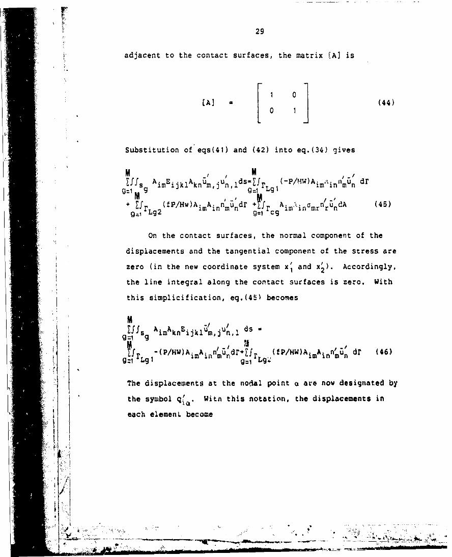
Substitution of eqs(41) and (42) into eq.(34) gives
M M ,_nIffS AimEijklAknUmjUn ldS ;Ur (-P/HW)AiminrlmUn dr
gzl M g= Lg 1M ~' MUr (fP/Hw)Ai A n' u dr + 1rAi A a n undA (45)
im in m n +Ir i in mrrngzI Lg2 g=1 cg
On the contact surfaces, the normal component of the
displacements and the tangential component of the stress are
zero (in the new coordinate system x' and x'). Accordingly,
the line integral along the contact surfaces is zero. With
this simplicification, eq.(451 becomes
M g -, / ds -gfsi kimkkn'ijklum,jUnI
UrJ" -(P/HW)Ai Ainnmundi'*Zfi' (fp/HW)A.mAinnun dm (46)g:1 Lg I g=1 g'&
The displacements at the nodal point a ar•e now designated by
the symbol q!. With this notation, the displacements in
each elemenL become
5!~j
ii
::".'i + " " ':'" ,, " " "

30
r /
ui N1i Qi
Ui N a q io (47)
N a is the shape function given in Appendix D. The
calculation now proceeds along the line developed previously
for problems involving either a single hole or two holes in
parallel (Section 3.4.1). The stiffness matrix of the g-th
"element is defined as
Kg f A ds (48)mono "f 9f~ Aim kn ijkl MiNO'j
As before, the nodal displacements qi, are independent of
the surface and line integrations. Thus eqs(48)-(4!9) yield
t Kg9~n• n * " -(P/HW)A. A. n'N drmono no Lglqm( im in ~n8 d
1r (P2 /HW)Al A n#N dr (49)
Lg2 ~ in
The nodal displacements are arbitrary functions. Thus
eq.(49) can be written as
A •mna no too (SO)
Uhere and t are gien by
flno K9 mono(51)U-t
/
a i
--. ,,. i. -• • • • - • ,

31
M
"m8 J..(frLg- (P/HW)AimAinnn N dr
+ frLg2 (fP/HW) Aim Ain n N Bdr) (52)
The elements of Km8 n and the components of the vector Fma
are known, provided that the components of the matrix (A] in
eq.(50), are known. Hence, eq(50) can be solved, once the
contact angles have been determined. This can be
accomplished as follows.
Values of U and 0L, e8 U and 0a are assumed such that
8aU and 6aL are greater than n/2. The displacements ui are
then calculated from eqs (41), (42) and (47). Using
eqs(I1), (14), (41) and (42), the normal stresses along the
contact surfaces bounded by the arcs 08aU and OaL are then
calculated. For contact angles greater than the actual
contact angles compressive stresses become tensile (stress
reserval), as illustrated in Figure 9. The angles 9a andUaL re then decreased slightly (by one grid length, say),
and the stresses are calculated again. This procedure is
repeated until no reversal in sign of the normal stressesIoccurs along the arcs, 0 to 8 and 0 to 8L (I.e., both
contact surfaces are in compression) . These values, and
S.L' are taken to be the contact angles. As an illustration.
values of the contact angles were calculated for Fiberite
T300/1034-C composites with different width ratios. The
variation in the contact angles with the width ratios are
given in Figure 10.

32
U eu$I
L LeL~eL
L 6
Figure 9. llustrtion otheRevrsalofthe Normal*Streeies When the Assumed Contact Angles ,and . are Greater than the actual ContactUAngles (Left). No Stress Reversal Occurs forthe Actual Contact Angles OU and *L (Right)$
, L
-, - -- -

33
4O N
00
0 d
we0.4
(0c 'U00
0~~ Ol0%A0
(884 P) 8 -lE)V LOJLNO
0ý7. 7oi

SECTION IV
PREDICTION OF FAILURE
In order to determine the load at which a joint fails
(failure load) and the mode of failure, the conditions for
failure must be established. In this investigation, the
joint is taken to have Zailed when certain combined stresses
have exceeded a prescribed limit in any of the plies along
a chosen curve(denoted as the characteristic curve). The
combined stress limit is evaluated using the failure
criterion proposed by Yamada-Sun (28].
4.1) Failure Criterion
Numerous criteria for failure have been proposed in the
past (29, 30-33]. Although the concepts underlying the
different failure criteria may be different, the results of
the various criteria are generally quite similar. in this
investigation, the Yamada-Sun failure criterion was adopted
(28]. This criterion is based on the assumption that just
prior to failure of the laminate ,every ply has failed due
to cracks along the fibers. This criterion states that
failure occurs when the following condition is met in any
one of the plies
) (oXy/S) 2 - e2 ,e no failure (53)
.e fi failure
./
":• • 'O'-' -" 14 "" ' -

35
As indicated in eq. (53) failure occurs when e is equal to
or greater than unity. In the above equation, ax and Xy
are the longitudinal and shear stresses in a ply,
respectively (x and y being the coordinates parallel and
/ normal to the fibers in the ply). S is the rail shear
strength of a symmetric, cross ply laminate [O/O/s, X is
either the* longitudinal tensile strength or the longitu$ nal
compressive strength of a single pay. The tensile strength
(X-Xt) is used when the stress ox is in tension (o,>O). The
compressive strtngth (X-Zc) is used when o is compressive
(ox <0).
4.2) Failure Hypothesis-Chara.cteristic Curve
The hypothesis is proposed he%-e that tailure occurs
when, in any one oif tsite plies, the --ombined stresses satisfy
an appropr ate y-chosen failL,-e criteri•'n at any point on a
characteristic curve. The cho cteor-stic -urve !'Figure 11)
is specified by the expression
r(8) D/2 R (RC. -R cos5
The angle m, easured clurckvise tro the a -X2 aXA.sk WAY
;.:ange in value frz -r/2 to 1/2. a and P are refer.-od to
as the characteristic inths tor tension and coopression.
A 1- -
Kl 11'.

S~oo
CHARACTERISTICCURVE
R L ii
-, I
¾c:. A.
#'su~s U. DScription Of the, Char4ceorstic Curve.* I!
I.-'
•"_ _ _ __ _ _ _ __ _ _ _ _ __ _ _ _ __ _ __"__ _ _ _ __ _ _ _ _

t !37
These parameters must be determined experimentally.
The concept of the characteristic length in tension Rt
was introduced by Whitney and Nuismer (34-37]. In recent
years, several investigators utilized this concept in
analyzing the strength of loaded holes. However, different
investigators used different definitions of Rt, and employed
different procedures for determiring the value of Rt. As
will be discussed in Sections VI and VII, the method
proposed here for determining Rt differs from that proposed
by previous investigators (7, 34, 35]. It is also noted
that the characteristic length in compression Rc has not yet
been employed ".n the strangth Rnalysis of loaded holes.
in this investigation, the characteristic curve is used
together with the Yamada-Sun failure criterion. Accordingly
(see e'q. 53), failure occurs when the parameter e is equal
to, or is greater than unity at any point on the
characteristic curve
No failure e < 1 at r r (55)
Failure e Z 1
It is emphasized that the above failure hypothesis is
used here in conjunction with the Yamada-Sun failure
criterion (eq. 53). However, the hypothesis is general and
is not restricted to the Yamada-Sun criterion. The
characteristic curve proposed here may be used with any
other failure criterion.
i '

38
[ 4.3) Solution Procedure
Whether or not a joint fails under a given condition is
determined as follows. For a given load
a) The components of strains of 1,1' £22 and c12 are
calculated, using the method of solution described in
Section III.
b) The lcngitudinal and shear stresses in each ply are
calculated using eq.(16'.
c) The parameter e is calculated (eq.53) along the
characteristic curve.
1'd) If e equals or exceeds the value of unity (eal) in any
ply along the characteristic curve, the joint is taken
to have failed.
The procedure outlined above is used to predict whether
or not failure occurs under a given load. Due to the
assumption of a linear stress-strain relationship, the
calculated stresses are linearly proportional to the applied
"load P. This fact, together with Yamada-Suh Zailure
I criterion (eq.53) gives
This relationship is utilized to determine the maximum
load (P~x) which can be imposed on the joint. For a given
ma

39
load P, values of e are calculated on the characteristic
curve, as discussed above (points a-d). Note that there are
two characteristic curves when there are two holes. The
highest value of e (eo) is then determined, and the maximm
load is calculated by the expression
Pmax P/e (57)
The calculation procedure described in the foregoing
also provides the location (angle Of) at which e first
reaches the value of unity (e-1) on the characteristic curve
(Figurel2). A knowledge of Of provides an estimate of the
mode of failure. When Of is small (0f=00), failure occurs0by the bearing mode. When 0f=45 failure is due to
shearout; when 0 :900, failure is caused by tension.
In summary
-15 : 0I < IS5 bearing mode
30°O : S60, shearout mode (58)
A t int.aediate volues of at, failure may b* caused by a
combiPi~on oft thes* modes.
A
4,¢
41:j
- /. • -... -. : • .:•,• , ,' ,,. : •.•, , .•• .• <'. ,,.••'• • :", " •• •• :o• :•:..a .•.-•-- .• :: • • .• ..•, • ,,•.•,•,•,. ••;.•.. .N "-:,: ,,.... •,- . • . . .°5 ...... '. V" -"•

40
~X2
i~fCHARACTERISTIC
I
I~~~'iqure~~t~ý' 12 oaono ý7ue(~) ln h

SECTION V
NUMERICAL SOLUTION
A "user friendly" computer code (designated as BOLT) was
developed which is suitable for generating solutions to the
problem formulated in Sections III-IV. The required input
parameters and the output provided by the code are
summarized in Table 1. The input-output is illustrated by
the sample calculations included in Appendix E.
In order to assess the accuracy of the numerical method,
solutions were generated to problems for which analytical
solutions were available. Specifically, stress
distributions were calculated in isotropic plates containing
both unloaded (open) and loaded holes, and in orthotropic
plates containing unloaded holes.
An analytical solution for the stress distribution in an
infinite (w c• ) isotropic plate containing an unloaded hole
was given by Timoshenko [381. The stress distribution in
such a plate was also calculated by the present method. The
parameters used in the numerical calculations are given in
calculation to approximate an infinite plate. The results
of the present method and the analytical solution of
"Timoshenko are compared in Figure 13. There is excellent
agreement between the stresses calculated by the two
methods.
• 7 : 41
/ -. . ...
. ?_
C DA'

42
Table 1. Input parameters required by the computer code andthe output provided by the code.
INPUT PARAMETERS
1) Material Properties
a) Longitudinal and transverse Young's moduli; EI and E2
b) Shear modulus, G12
c) Poisson's ratio, U12
d) Longitudinal tensile and compressive ply strength,xt and XC.
e) Rail shear strength of a cross ply laminate
[0/901s 5 0
f) Characteristic lengths, Rt and Rc
2) Geometry
a) hole diameter, D
b) thickness, H
c) width, W
d) length, L
e) edge distance, E
f) distance between two holes, G (for two holes only)
3) Ply orientations
OUTPUT PARAMETERS
1) Failure load
2) failure mode
-/

43
x2
1 o PRESENT METHOD
4-0- TIMOSHENKO4.0- •x
lb if#R
•3.0 r
(I,
(,
2.0o
..0 - L 0-
0 2 4 6 8 10DISTANCE, x/ R
!Figure 13. Stress a2 Along x -,•XiS in an Isotropicinfinite 2Plzte CoAt-iining a Circular Hole.Comparison of Prese-it Results with TheoreticalResults Given by Tituoshenko [38). ParametersUsed in Numerical Colculations: 5w2.37 ksi,D-ZR-0.3 in. W/D-1,. E/D-8, L/D-28.
! I
ii
SI
44
The stresses in isotropic plates containing loaded holes
were also calculated. Plates of infinite and finite width
were considered. Calculations were performed for the
parameters given in Figure 14.
As shown in Figure 14, the stresses calculated by the
present method are in excellent agreement with De Jong's
approximate solution [24].
The stress distribution in an orthotropic plate of
finite width containing an open (unloaded) hole was also
calculated. The calculations were performed for a plate
with the symmetric laminate lay up of [0/90] . An
analytical solution for this problem was provided previously
by Nuismer and Whitney (35], who modified Lekhnitskii's
earlier solution (39] for an infinite plate. The results
given in Figure 15 show excellent agreement between the
stresses calculated by the present method and by the
analytical solution.
The aforementioned comparisons indicate that the present
method predicts the stress distribution around loaded and
unloaded holes with high accuracy.
t1
'I
__ _ __ -
-. - --i* * *

45
o PRESENT METHOD
- DeJONG PB
--1.5- I 2R
Cn 1.0 -0.
p
(I)
0.5 -
0 2 3 4 5 6DISTANCE, x,/R
Figure 14. Stress 02 Along the x -axis in an IsotropicPlate of Finite width Containing a Loaded Hole.Comparison of the Present Results With theTheoretical Results Given by De Jong [24).Parameters Used in the Numerical Calculations%DgO3 in, V/Dw5, E/D=4, L/D'14.
• 1
A. -
'. .- -•i

46
T E2
Q PRESENT METHOD L E
-- NUISMER-WHITNEY
S2R~
lbt
Ib
4.0-w
( ,
2.0-
I 1 _ . _ .. L I I ..
o0' i.0 i.Z. 1.4 1.6 1.8 2.0DISTANCE, x, /R
Figure 15. Stress a Along the x -axis in an OrthotropicFinite Pate [0/90] taining a Circular Hole.
Comparison of the pResent Results with the
Theoreticla Results Obtained by Nuismer andWhitney [34]. Parameters Used in the NumericalCalculations: Materijl: Graphite/EpopyT300/5208, i-21.4xl0 ksi, 5EKl.6xl0 ksi,
,-0.77x10 ks1,U1-.0.29, a-.3 ksi,D-, in, W/D-3, E/DF-, ",/D.14

7jSECTION VI
EXPERIMENT
An experiment was performed to measure the mechanical
properties of composite laminates (with and without holes),
and the failure strengths and failure modes of mechanically-
fastened composite joints.
The apparatus and procedures used in the tests are
described in this section. A brief description of the
procedure used to fabricate the test specimens is also
given.
6.1) Measurement Procedure for the Laminate Shear Strength S
Rail shear tests were performed to measure the laminate
shear strength. Cross ply [0/901s laminates made of either
20 or 24 plies were used in the tests. Laminates with
different volume fractions v of 0 plies were tested. is
4 the number of zero degree plies divided by the total number
of plies.
Tbe specimens ranged fcom 8 in to 7.75 in in length and
2 in to 1.5 in in width. These specimen dimensions were
selected because it was demonstrated by previous
investigators that for such specimens, edge effects are
negligible (40,41]. The configurations of the rail-shear
specimens are shown in Appendix E.
47Al

48
'LOAD TESTSPECI MEN
1/" /1"Do.3/16"I Dia.
+ ~~Holes --
1" (8 Holes+ + on each -
side)
3/4" x3/4
8"+t Steel Plates--
+ +
++
+ +
-,y
t LOAD
Figure 16. Schematic if Rail Shear Test Fixture.
q F

49
Light 3/16 in diameter holes were drilled along two
sides of the specimens, as illustrated in Figure 16. The
specimens were placed between a rail-shear fixture. The
geometry and dimension of this fixture are given in Figure
16. The specimen was fastened to the rail-shear fixture by
16 bolts. The bolts were tightened to at least 80 ft-lbf
torque.
The shear tests were performed by placing the rail-shear
fixture into a mechanical testing machine and by applying a
compressive load. The ultimate failure load of the laminate
was recorded.
6.2) Measurement Procedure for the Characteristic
Length R
The characteristic length R "as measured usingt
rectangular specimens with an open hole in the center of the
specimen. Tests were performed with specimens having
different ply orientations. differen- hole si:es, and
different dimensions (Appendix F). During each test. the
specimen was subjected to a tensile load and the ultimate
load was recorded. in addition, (after failure) the
specimens were inspected visually to establish the uode of
failure. "
*1 from the measured tensile strength the value of R wast
determined as follows
At the failure load, the stresses in the laminate were
r
-U

50
calc-lated, using the model described in Section III for a
laminate containing and open hole. The stresses calculated
in each ply along the 0=90 line were substituted into the
Yamada-Sun failure criterion (eq. 53). The point
along this line was found at which the value e became unity.
The distance between this point and the edge of the hole was
taken to be Rt. The values of Rt thus measured are
presented in Section VII.
6.3)Measurement Procedure for the Characteristic
Length RI
The characteristic length Rc was determined by the
following method. A single hole was drilled into the
specimen. The position and the diameter of the hole. the
specimen geometry, and the laminate configurations used in
the tests are given in Appendix F. The specimen was
inserted into a fixture shown in Figure 17. The top part of
the fixture consisted of two 3 in wide and 5 in long steel
plates (main plates*). A 1.25 in diamete. and 3.5 in long
rod was inserted between these plates. The rod was !astened
to the main plates by bolts. A 0.2 in diameter hole was
drilled along the center line o! each main plate, 1.5 in
from the bottom edge. A 0.5 in dowel pin was inserted into
this hole.
The bottom part of the fixture consisted of two 3 in
S.-. •

i•, 51
Steel Rod-- Dic: 1.25"
Length 3.5"
Steel Main Plates---- Dowel Pin. . (5" x 3"x 3/s•') 1/2 Dia.
>.;:, "-"--3/i6" Dia Bolts
Steel Base Plates(3 /•' x 3"•x 1/)
- Dowel Pin.. - ..- 1/2" Dia.
S--Dowel Pin1/4" Die.
I I
I I
iiI I
,,.,-Specimen
Figure 17. Fixture Used in Testing Loaded Holes (Base Plate
Geometry Given in Figure 18 and Table23).
.777
~ON
i!,• . . . . ' . . ,ll •.•• ". . o •

52
wide and 5 in long "base plates." These plates were
supported by the dowel pin. The material to be tested was
placed between the two base plates. A second 0.5 in
diameter dowel pin was passed through the base plates and
the laminate.
A C clamp was placed around the base plates near the
lower dowel pin and tightened by hand. The purpose of this
clamp was to simulate the lateral force which would be
[ provided by "finger-tight" bolts in the hole.
During the tests the rod protruding from the main plates
was inserted into the upper grips, and the laminate was
inserted into the lower grips of a mechanical testing
machine. A tensile load was applied by the machine and the
ultimate tensile strength was recorded.
From the measured tensile strength, the characteristic
length Rc was determined . The stresses were calculated
using the model described in Section III for a loaded hole.
I A value of R was assumed and the characteristic curve wasc
constructed in the manner given in Section IV. The value e
in the Yamada-Sun failure criterion (eq.53) was determined
* Iin each ply along a segment of the characteristic curve,
I ranging from 0-15 to G--15. The procedure was repeated for
different assumed values of Rc until (in any ply) the value
e-l was reached along the characteristic curve segment
(-15:e5+15). This value was then taken to be Rc. The
measured values of Rc are presented subsequently (Section
7.3).'I

53
6.4) Strength of Mechanically Fastened Composite Joints
The strengths of mechanically fastened joints (loaded
holes) were determined using rectangular specimens. Either
a single hole or two holes in parallel or in series were
drilled in each specimen. The geometries of the specimens
and the laminate configurations used in the tests are
described in Appendix G.
The test was performed by placing the laminate into the
fixture described previously and illustrated in Figure 17.
In each test the same main plate and the dowel pin were
uesd. The dimensions of the base plates were different,
depending upon the specimen configurations. The dimension
of the base plates are given in Figure 18 and Table 2.
During the test, a lateral f4rce was applied with one C
claanp to simulate the lateral force that would be provided
by 'finger-tight* bolts placed in the hole. The fixture was
inserted into a mechanical testing machine. A tensile load
was applied and the ultimate tensile strength as recorded.
After the test, each specimen was inspected and the mode of
failure was determined.
54
6,5) Specimen Preparation
The laminates were constructed from Fiberite ?300/1034-C
prepreg tape. The panels were cured in an autoclave [43).
The test specimens were cut by a diamond saw. The holes
were drilled with solid carbide drills for hole diameters
less than one half inch anO by carbide tip drills for 1/2 in
diameter holes. The nominal sizes of holes were 0.125 in,
0.1875 in, 0.25 in, and 0.5 -in. The nominal size dowel pins
were the same. To provide a close fit, each dowel pin was
dressed down by about 0.001 in. The properties of Fiberite
T300/1034-C are listed in Table 3.
I
* i
* a
II
* I i
I,

55
,I I
a lC
CII
........

56
Table 2 Dimensions of the base plates shown in Figures 17and 18. All units in inches.
Single Hole D G E
plate 1 0.5 1.5
plate 2 0.25 1.0
plate 3 0.1875 0.75
plate 4 0.125 0.5
Two Holes in Parallel
plate 1 0.5 2.5 1.5
plate 2 0.5 1.5 1.5
plate 3 0.25 1.25 1.0
plate 4 0.25 0.75 1.0
Two Holes in Series
plate 1 0.25 1.25 0.75
plate 2 0.25 0.75 0.75
plate 3 0.1875 0.625 0.5
plate 4 0.1875 0.375 0.5
t, i
I

5;
Table 3 Properties of Fiberj.te T300/1034-C craphite/epoxycomposite
Longitudinal Young's modulus, 1l m 21300000 psi
Transverse Young's modulus, E2 a 1700000 psi
Shear Modulus, G12 n 897000 psi
Poisson's Ratio U12 a 0.3
Longitudinal tensile strength, Xt a 251000 psi
Longitudinal compressive streiigth, Xc - 200000 psi
Rail shear strength, S-S5 0 U 19400 psi
Characteristic length in tension, Rt U 0.018 i.!
Characteristic length in comFression, Rc * 0.07 in
I :w

SECTION VII
MEASUREMENTS OF S, Rto AND Rc
Tests were performed to determine the rail-shear
strength S and the characteristic lengths Rt and Rc of
Fiberite T300/1034-C composites. These data were generated
because they are required in the numerical calculation of
the failure strength and the failure mode of loaded holes.
The data obtained also indicate the sensitivities of S. RtV
and Rc to such parameters as specimen geometry and laminate
configuration.
The material properties used in deducing S, Rt. and R
from the measured data are listed in Table 3. In these
tables the values of S. Rt, and R c obtained in this
investigation are also included.
7. 1) Rail Shear Strength_S
Rail shear tests were performed with symmetric cross-ply
laminates [0/901s having different volume fractions of zero
degree plies and different geometries. The test conditions
and the test results are summarized in Appendix F. During
some of the tests, cracks were observed near the top and
• I bottom holes of the rail-shear fixture. These c€racks
resulted in a reduction of shear strength. Specimens with
such cracks were not used in calculating the rail-shear
strengths. Accordingly, the rail-shear strength of cross-
- -! .. ..... . .

59
ply (0/90) specimens having 50 percent zero-degree plies by
volume was found to be S50 =19.4 ksi.
The rail-shear strength depends on the volume fraction
of the zero degree plies in the laminates. At volume
fractions above 50 percent the rail shear strength decreases
(Figure 19). At volume fractions above 60 percent the rti±
shear strength remains nearly constant. Therefore, when the
volume fraction of zero-degree plies is higher than 50
percent, the rail-shear strength corresponding to the
appropriate volume fraction should be used in calculating
the failure strength and the failure mode.
It was observed that the shear stress to shear strain
relationship was nonlinear. However, in the present model,
this nonlinearity was not taken into account. The
assumption of linear stress-strain -elation may result in
some error in the calculated values of the failure strength
(Section VIII), especially for joints consisting
predominantly of 10/901 and [t451 laminates.
7.2) Characteristic lenqth R
The characteristic length R was determined using{tilaminates with difievent geometries and different ply
orientations. The detailed results of the measurements are
given in Appendix F. The data are summari:ed in Figures 20
and 21. Each data point in these figures is the average of
four measurements. Figure 20 shows the variations in Rt
with .aminate lay up. :n Figure 21. all but one set of data

60
are presented in a single plot. The data for [(±45)]
laminates were excluded from Figure 21, because with these
laminates failure occurred not by tension, but by tear-out
along the 45 dwgree fibers.
The results in Figure 20 show that the value of Rt
depends on the hole diameter, the width ratio (W/D), and the
ply orientation. The value of Rt increases with increasing
hole diameter (Figures 20 and 21). As was discussed
previously (Section 4.2), different investigators use
different definitions of the characteristic length. It is
still noteworthy that an increase in characteristic length
with hole diameter was also observed by Whitney and Nuismer
[34, 35] and by Pipes et al. (7) in their tests with
T300/5208 and AS-3501-6 graphite/epoxy laminates. It is
difficult to discern definite trends in Rt with width ratio
and ply orientation. In calculating the strength of loaded
hole, the Rt value appropriate to the laminate and hole
configurations should be used. When this value is
unavailable, an approximate value of R must be used..1tA -Fortunately, it was found that strength prediction is not
too sensitive to the value of R . For example, the failureit
strengths of loaded holes in T300/1034-C laminates were
calculated with the values of Rt *0.007, 0.018, and 0.04 in.
v} The use of tht lowor and higher Rt values yielded failure
strengths which were about 10 percent to 20 percent
different from the one obtained by the average R value
(Yt-O.018 in )
4.-

61
T300/i034-C"o [0/90]S
_0.8z
W 0.4
JS0.2
0 50 60 70VOLUME FRACTION OF 0 PLIES u0 (percent)
Figure i9. variation in Rail Shear Strength with theVolume Fraction of 0 Degree Plies of Cross PlyLaminates. o Data. - Fit to Data. S50-50% Volume Fraction of 0 Degree Plies -19400 psi
I'
;ji ~ -- - -- ---- - .

62
0
000
00 0
C -6
NO-IN

63
T300/i034-C
w 0.04-JU Q
00 S-- -- - - - - -- - - -
0.25 0.50HOLE DIAMETER D(in)
: i Diatmeter. Wta• are for Laminate Coantgurati•onseGiven in P.•'e 20.
I
,.?

64
7.3) The Characteristic Length R
The value of Rc was determined for four different ply
orientations, as indicated in Appendix F. The data are
summarized in Table 4. Each Rc value in this table is the
average of four measuremen:ts.
As was discussed in Section 6.3, the values of R werec
obtained from data generated using loaded holes and from the
Yamada-Sun failure criterion (eq.53). Both the longitudinal
and shear etresses play a role in this criterion. Thus,
both of these stresses may affect the value of Rc. The
shear stress has a significant effect in those laminates in
thich the shear stress to shear strength ratio (ay/S) is
comparable to the longitudinal stress to longitudinal
compressive strength ratio 'ox/Zc), This situation arises,
for example, in [0/90]s and (±45]s laminates.
In calculating R , the stresses were assumed to vary
linearly with strains. As was noted previously (Section
S I61). for shear stresses this assumption may be invalid.
since the value R may depend on the shear stress. This
assumption may have affected the valmues o! R•, especially
for the tvo ccoss-ply 1**inate% in Table 4. The cffects
introduced in AC by the assumption of linear stress-strain
relationship is un~novn; theretove, the value of R (w-.07
in.) obtained to: qusi-itotropic laminates vas adopted in
this investigation.
;= i
-I

65
Table 4 The Characteristic Length in Compression Rfor Fiberite T300/1034-C. Data obtained fSrD=0.25 in, W=2.0 in, L=7.0 in , E-1.25 in
Ply Orientation Characteristic Length Rc (in)
[(O/±45/90) 3J5 0.07
B(902/±60/±30)2]s 0.08
[(0/90)6 1 0.09
S[±45) 6]3 0.13
, I
1i
t

SECTION VIII
EXPERIMENTAL VALIDATION OF THE MODEL
In this section, comparisons between data and the
results of the model are presented. The data used in the
comparisons were generated during the course of this
investigation with Fiberite T300/1034-C graphite/epoxy
composite having different geometries and different ply
orientations. The failure strength and the failure modes
were measured with composites containing either one pin-
loaded hole or two pin-loaded holes in parallel, or two pin-
loaded holes in series. The experimental results are
presented in Figures 22 through 29.
To facilitate comparisons between the data and the
results of the model, the ordinates in these figures
represent the bearing strength PB' For laminates with a
single hole or with two holes in series, the bearing
strength is expressed as PB= P/DH. For laminates containing
two holes in parallel, the bearing strength is taken as P
P/2DH. P is the failure load and DH represents the cross
sectional area of the hole. In Figures 22-29 the measured
bearing strengths and failure modes are represented by
different symbols.
Tie bearing strengths and failure modes were also
calculated by the model. The numerical calculations were
performed using the material properties listed in Table 3.
The numerical results are included in these figures. The
66

67
calculated bearing strengths are given by solid lines. The
calculated failure modes were not identified separately as
long as they were the same as those given by the data. In
those cases where the calculated failure model differs from
the data, the calculated failure mode is identified by the
letters T, B, or S, next to the corresponding data point.
These letters represent failure in tension, bearing, and
shearout modes.
As indicated in Figures 22-29, for [(0/±45/90)3]s and
[(902/±60/±30)2] laminates the calculated failure strengths
agree with the data within 10 percent to 30 percent. The
specimen geometry (hole diameter, edge distance, and width)
has little effect on the accuracy of the model.
For cross-ply laminates([O/90] and [±45]s) the5 S
difference between the calculated bearing strengths and the
data ranges from about 10 to 40 percent. The accuracy is
better for smaller holes (10 percent for D= 1/8 in) and
j decreases the hole size increases. The differences
between the calculated and measured bearing strengths become
' about 40 percent for 1/2 in diameter holes. In all cases,
the calculated values are conservative and underestimate the
actual bearing strengths. The veason for the lower accuracy"of the model for cross ply laminates is most likely due to
the assumption that the shear stress is linearly
proportional to the shear strain. Since shear stresses are
important in determining the failure strengths of cross ply
laminates (Section VII), the use of nonlinear shear stress-

68
strain relationships should improve the accuracy of.the
model for such laminates.
The results in Figures 22-29 show that the model predicts
the failure mode with good accuracy. Of the 83 specimen
configurations tested, the model failed to predict
accurately the failure mode only in 9 cases - - these cases
being indicated by the letters, T, B, or S, in Figures
22-29. In 3 of those cases where the model gave different
failure modes than the data, the data were ambiguous.
Failure, in fact, may have occurred by the combination of
two different modes.
The results discussed in the foregoing, and represented
in Figures 22-29, show that the model provides the failure
strengths and failure modes of loaded holes with reasonable
accuracy. The accuracy of the present model could be
improved further if, instead of the average values of S, Rt
and RC, the values corresponding to the specific geometry
and laminate configuration were used in the calculations.
It is worthwhile to compare the accuracy of the present
model with the accuracy of the models developed by previous
investtgators. A summary of the accuracies of the various
models is presented in Table 5.
The accuracy may depend on the geometry, ply
orientation, and material properties. Therefore, the
accuracies in Table 5 must be viewed with caution.
Nevertheless, the numbers in this provide an estimate of the
magnitudes of error of the different models. The present
, . -- - - - --

69
"model appears to be more accurate than any of the other
models.
Two points are worth noting: First, the models
developed previously apply only to laminates containing a
single hole. None of the models except the present one
applies to laminates containing two holes. Second, of the
existing models, only the present one and the one by Garbo
"and Ogonowski (61 have been supplemented with *user
friendly' computer codes. Therefore, presently, only these
two models can be used readily. Furthermore, the Garbo and
Ogonowski model yields the failure strength, but does not
provide the mode of failure.
/,

70
150 [(O/±45/90)3]5 -(90/-260/- 30) ]S,a5 _/D5
01W/0=3 ()50- " .E/D 3 (B)
#p T300/1034C
15 0- [0/(!45)3/ 'qo 3]5 - [(0/so l6,]
1t001003 W/WDD5
50 3
, 150- [ / 4 ) q1b- [o I -' 5)2/ o•]s[(._45)f,
U "5ý D(T)
W/D -3
O' a I I _ I _ I I I I
10.
'-0'0 025 0.5t50 [0/45/907]5 DIAMETER, D (in)
100- LTA BEAR- SHEARW/O TENSION ING OUT
50 - 5 3 5
II MODEL -
0 0. 5 0.5
DIAMETER, D (in)Figure 22. Bearing Strengths of Fiberite T300/]034-CDIAM0ER034-CLaminates Containing a Single Loaded Hole.Comparisons Between the Data and the Results ofthe Model. The Failure Modes Calculated by theModel are the Same as Those of the Data UnlessIndicated by a Letter in Parentheses next tothe Data Point.
• /

* 71
150 - (0/ ±45/90)3 1s "[(902/±60/ ±30)213
0 T300 / t034-C
100 0=0.i875in
50- E/D 2
0 L 1 L1 L L I I l
'50 [(0/(t.45),90,3]) (O/90]
I-
(-0/ (!45)2/90o53 ((t456 is
ztoo-7~00
0i 0
J 50
0 1 1 l I I I I I J0 5 10
(0 -[/45/907 WIDTH RATIO, W/D
DATA100 o TENSION
0 BEARING
50_ * SHEAROU'"
-MODEL
-0 5 toWIDTH RATIO, W/D
Figure 23. Bearing Strengths of Fiberite T300/1034-CLaminates Containing a Single [oaded Hole.Comparisons Between the Data and the Results ofthe Madle. The F'ailure Modes Calculated by theModle are the Same as Those of the Data Unl,.ssindicated by a Letter in Parentheses next tothe Data Point.
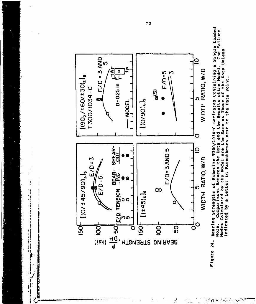
72
*0
0-i
0~~ In-__ _ _ _ __ _ _ _ Oui at
1 0 %W W4+1 tý 0 0 g
0 4)4jt+ = c 4)S
_u 0
cS~00 toa0n 0~ 0
4, 0 ton c
X 0 0*jai 0 w
M c 0ad
cr. 0
000
0 .0
(A C 00.N0 6
HA 0OS4) HION81S N13
djJbg
N o 6

73
0
0 EO
It -1-14) .
m.
U
00
I') I C~0)
0 L) fl
0~
.L~Lo ajo 4t1
It~ CohN...
t00V)tf 00 (D VVj L
N K) 0 .d.-4
0 0 0 00 0 0 ~
H(12)
o 0)4 - Li31SO183

74
0
r-" II I n
0E~0
- oto00 #--% a
k.o - ANQa0 co 00
0 0
0 N.C
-r 00
0 .". a4
00 A 04 4* w 0jI
~0 N
Qt -
00
00) c) 0
-SX -3'H.LSN38iS O1V1
.16
7/ ý0

75
200o0•o/,45/9• 9 3 '(90 /_6oI-3o),]S
0-9s)
100 G/D 3 AND5
a.l• G/D TENSION SHEAROUT
. 50- 3 o 05 0 U
MODELz .0 t I I _ _ _ _ _ _ _ _ _ _ _ _
200 O- [(:t45),ls-[09•1(n ((0/9015J W
_9 150 - T
,• o~~(S) 1Li OZS0(S) )co i00 - 0o /*
50 -/ 3AND G/Da 3 AND 5
0 5 10 0 5 10WIDTH RATIO, WID WIDTH RATIO, W/O
I
Figure 27. Bearing Strengths of Fiberite T300/1034-C
Ladinates Containing Two Loaded Itoles in Series.
"V Comparisons Between the data *nd the Results okthe Model. The Failure Modes Calculated by theModel are the Same as Those of the Data UnlessIndicated by a Letter in Parentheses next tothe Bata Point.
I)
-

76
2..00- \ (0/!t45/90)35 -[((90,/a60/t30)lzs0 T300/1034- C
"- 150
~ ¶00 W/D:1I00- 5 ý
DAT7A 4jiý TENSION SHEARQUT
T 50- 3 05 0 U MODEL-z 5 C) 2
I t I
20 (.45)6 [(O/90)61$E
q \E/Oz3LW O(S)
100-
50 4- ..3
025 05 025 05DIAMETER. O(•t) OIAMET.R, O(irt)
11
Figure 28. Dearinq Strength2 of I'iberite T3OO/1034-CLaminate5 Containing Tuo Loaded Holes in Series.Cooparisotis Setveen the Data and the Results ofthe Model. The railure Modes Calculated by theMod-el are the Same as Those of the .ata Unlessindicated bT a Letter in Parentheses next tO
the Data Potnt.
3;,
7 '111.: .

77
0 C
00to 0~
E4
0 00.~
0)0
0 (:j
NO%0 0<00ý -l a01 6ro so
0 S
t~ I
'Cap,
00u
C- t

78
LI uo o
0 0j
E 0 in 00 t Ln
-44
o ~ 0
ONN
~v v
& Q 0 04
.4-
~~00
*0

SECTION IX
DESIGN CONSIDERATIONS
As illustrated by the sample computer input-output in
Appendix E, the model, together with the computer code, can
readily be used to calculate the failure strengths and
failure modes of laminates containing a single pin-loaded
hole, two pin-loaded holes in parallel, or two pin-loaded
holes in series. The model can also be used to design
joints containing many pin loaded holes. In joint design,
it is desired to determine the number of holes, the hole
diameter, and the hole positions which result in the maximum
failure load P and the maximum failure load per unit weightP The failure load per unit weight is defined as
*I • /w(59)P mP/W
where P is the failure load, and w is the combined weight of
the composite wc and the pin w5
I.-wwc + w (60)
In this section, procedures suitable for calculating PM
and PM are illustrated via two sample problems. In these
problems, the failure load of 24-ply (thickness H-0.125 in)
[(0/±45/90)3 Fiberite T300/1034-C graphite-epoxy
composites are determined. The material properties used in
"79

30
the calculations are listed in Table 1. The density of the
composite is PC n 0.00194 ibm/in3. The pia or pins are
assumed to be 3/4 in long and to be made of steel (density
Psm 0.0093 ibm/in').
The calculation procedures are presented in Section 9.3
for joints containing one or two holes, and in Section 9.4
for joints containing three or more holes. First, however,
interferences between two aujacent holes, between the edge
and an adjacent hole, and between the side and an adjacent
hole are discussed.
"9.1) Interaction Cuefficients
It is desired to know under what conditions, if any, the
proximity of two holes, or the proximity of a hole to the
edge or to the side of the laminate, affects the failure
load. The interaction between two holes, between a hole and
the edge, and between a hole and the side, can best be8 evaluated by the use of interaction coefficients.
Two Holes in Parallel The parallel hole interaction
coefficient g. is defined as
*1, P /(PH/2) (61)
Where P5 is the failure load of a GH wide laminate
containing a single hole, and P is the failure load of' a
2GH wide laminate containing two loaded holes separated by a

81
distance GM (Figure 30). When GM becomes large, the
interaction between two holes becomes small (PH/2 . ps).and
the interaction coefficient approaches unity (gH 1).
Two Holes in Series The series hole interaction
coefficient.gV is defined as
(62)
where P is the faiiure load of a laminate (width W)
containing two loaded holes separated by a distance Gv. PT
is the failure load of a laminate with the same width
containing two holes; one located at a distance E from the
edge, and the other located at the center of the laminate
(Figure 31). When the hole distance increases, the
influence of one hole on the other becomes small; the
failure load PV approaches P (Pv .P) and gv approaches
unity (9v . 1).
Edge Interaction The edge interaction coefficient gF is
defined as
9E PS/Pc (63)
where PS is the failure load of laminates (width W) with a
single loaded hole at distance E from the edge. PC is the
failure load of a laminate of width W with a hole in the
center (Figure 32). The influence of the edge on the

82
failure load becomes smaller as the edge distance increases.
When the hole is moved to the center (E-L/2), PS becomes PC
and the interaction coefficient becomes unity (gE . 1).
Side Interaction Coefficient The side interaction
coefficient gS is defined as
S /P (64)
where PH is the failure load of a laminate (width W)
containing two loaded holes separated by a distance W/2. PG
is the failure load of a laminate with the same width
containing two loaded holes separated by a distance GH (GH
W/2, Figure 33). As the distance Q between the side and the
hole increases P P and the interaction coefficient g
approaches unity.
9.2) Numerical values of the interaction Coefficients
in order to illustrate the trend in the interaction
coefficients these coefficients were calculated for Fiberite
T300/1034-C graphite-epoxy composite laminates with ply
orientations of [(0/t45/90)3))s and E(0 2 /45) 3 3. The
ii results, obtained using the computer code, are presented in
Figures 30-33. The most significant feature of these
results is that the failure load is not affected
significantly
,-. .
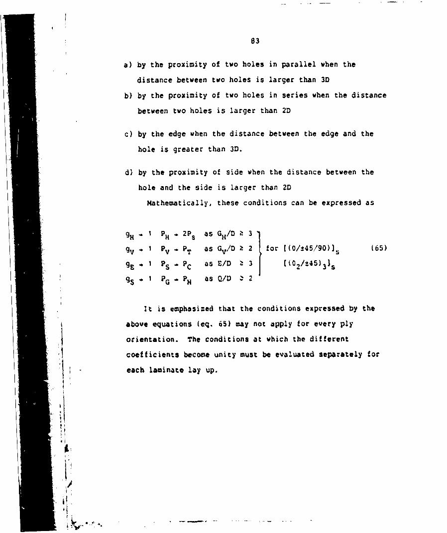
83
a) by the proximity of two holes in parallel when the
distance between two holes is larger than 3D
b) by the proximity of two holes in series when the distance
between two holes is larger than 2D
c) by the edge when the distance between the edge and the
hole is greater than 3D.
d) by the proximity of side when the distance between the
hole and the side is larger than 2D
Mathematically, these conditions can be expressed as
9H I P H 2Ps as GH/D a 3
gV ° I Pv " PT as Gv/D Z 2 for [(0/t45/90)), (65)
gE I PS PC as E/D Z 3 ((02/145)315
gS I P G PH as Q/D Z 2
it is emphosi:ed that the conditions expressed by the
above equations (eq. 65) may not apply for every ply
orientation. The conditions at which the different
I coefficients become unity must be evaluated separately for
each laminate lay up.

84
C
U) 0
0
(n'
in3
C~Co
+1 'UjLLJa
N C5J60 0
Y0
-i W
ON c5
Cl) 0)
dzIto
"d) 5d)
IN10-.r 0 N01OV8IN

85
0~iII 00.1.. 0
cr 00
C 0
0
to C) +1 Is iUl 0
+10N 0**- J390
(4
to 0
0 0,
I,0 J~ -.
lu
to do(D U.)in
CI)
d 4g01UJ0 NOIOWON
V-.

86
C'j
00
(0±1
U, I crUlU,
00
N -4
Qf 0-00
I 9)l~
C~C
0- I.
00On(
/S' sd 6'iN31:I--30:) NOLLOV83.LM 3903

87
[(0/145/90)315 DzO.5tn w .4
D 0. 125 in N0 -a: T3O0/!034-C ,•. /0-3, L!DzO E201
"v,,t W/o5 W/018 W/o 0a8
"L& U I!- 1/, wo,
/ ((0/ 45/90)3132
S• -((0=s/-45)31, - [(O2/ !40),1 15
II• ! W/O5" W/D=:
0 3 0SIDE DIS AONSOE DISTANCE RATIO, Q/0
Figure 33. Side interaction Coef•icient. Results of the Model.
[ii,*
¼

88
9.3) Laminates with One or Two Holes
In this subsection, a procedure is described which can
be used to size a laminate containing either one or two pin-
loaded holes.
We consider a laminate of known width (W-1 in), length
8(L- in) and thickness (H- 0.125 in ). The laminate may
contain either one pin-loaded hole or two pin-loaded holes
in parallel or in series, as illustrated in Figure 34.
It is desired tj find the number of holes ( one or two
holes), the hole diameter D, the edge distance E, and the
distance between two holes G, which result in the maximum
failure load P and in the maximum failuce load per unit
weight P M"
"The calculation proceeds along the following major
steps:
a) Using the computer code. the failure loads of
a laminate containing a single-loaded hole are
calculated for different hole diameters D and
for different edge distance ratios C/D.
The failure load is plotted versus the edge ratio
S/D (Figure 35). The desired edge ratio
W"1D) is selected.
Here, the edge ratio E/O-3 was selected because the failure
load reaches a MaXiMUM at the edge ratio of about 3 and
remains nearly constant at higher edge ratios. 7his
,,a

89
1"0 0 .GTGvT~Ko DT
L
IIfigure 34. D)es~?ipýicr 04 P-0b~e' Used~ ýr De~ig ..acinazesWith a Single Pin-Loaded Ho'le, b)* To Pin-Loaded Holes in P3Ca110., C) Two Pin-Loaded
,oles 5n Series.
*II,
I al !

g0
T300/1034- C
O 0.25 i
x I W I in. L=8in.
oU - -- wl-_t
0 2 4SEDGE RATIO, E/D
" i
SFigure 3S. railure Load as a *'unction at edlge Ratio tac' i •Liminates Containing a Single Pan-L~oaded Moles.• ' Reultsl at the Model.
0.
/
,DG R
A

91
value (E/D) will also be used for joints containing two
loaded holes in parallel and two holes in series. The
reasons for this choice of E/D are as follows: 1) For
parallel holes the interaction between two holes has almost
no effect on the failure load (gH . 1 and PH/2 , PS,
Section 9.2 ). Hence, when G /D>3 (as is the case in the
present problem), two parallel holes can be treated as two
independent holes. 2) For two holesin series, the
interaction between the holes is unimportant, when Gv/D>3
(gV * 1 and PV + PC, Section 9.2). Two holes can be
considered as two independent holes sharing part of the
total load. Hence the value of E/D=3 is a suitable choice
for the present problem when Gv/D> 3 .
b) Using the computer code, the failure loads are
'. I calculated for different hole diameters, and
for different hole separations G for two holes in
parallel and for two holes in series. The failure
loads are plotted as functions of the hole distance
ratio G/D (Figure 36, top). From these plots,
the maximum failure load PM can be obtained.
For the problem under consideration, the maximum failure
load is 5000 lb. This load is achieved by two 0.125in pins
in parallel separated by a distance GH-0.5 in (GH/D * 4).
c) Frcm the known values of the failure load P,
the failure load per unit weight P• is
calculated using the expression
A,

92
* 2P = P/AP WHL + a (rD /4)(PsLs-PLH)] (6f)
where L is the length of the pin. The
parameter a=1 for a single hole, a=2 for
two holes. The failure load per unit weight
is plotted as a function of G/D
(Figure 36, bottom).
For the present problem, the maximum failure load per unit
weight P*M is 8000 lbf/lbf and occurs with two 0.125-in
diameter pins separated by a horizontal distance G 0.5 in
(GH/D =4).
9.4) 1-!.iir.Ates with Multiple Holes
This problem is concerned with laminates containing
several pin-loaded holes spaced evenly, either in a single
row or in two parallel rows, as illustrated in Figure 37.
The number of holes in the laminate with a single row of
holes, or the number of columns in the laminates with two
rows of holes is
N 0 W/GH (67)
It is desired to determine the number of holes No, the
hole size D, the positions of the holes G and GV, and the
edge distance E, which result in the maximum failure load.
K7 77________77

* 93
U) c
ItL&j~~ '0
04
00
U-).0~0'0
E 00 FO 00o~~~ mooI'* IX-0
(f) 0 0or
0 it Q CA
M (A
CT) 4oNm 0
0oo
0 0) 0 CD
0~U
U -W
~~400
o. 00I'l ; j
ql~~~r Ej L-01XdI 3_Oj~~~9 X 'V-13MV
UNfl 63cd OVO'l 36flhivi
~, * l,

94
To 0
0 0 0
0
~0 00
VV
IL A WC.
0 7,

9•
The model developed in this investigation can be applied
only to laminates containing either a single pin-loaded
hole, or two pin-loaded holes in parallel or in series.
Therefore, the model can not be used directly to calculate
the failure load of laminate containing several holes. The
failurt loads of such laminates can still be estimated with
the use of the model by the procedure described below.
a) The interaction coefficients gB and gv are calculated and
plotted in the manner described in Section 9.1.
b) The ratios E/D and GV/D are selected, which correspond to
the conditions g. 1 and gV* 1. In this investigation,
C the values of both E/D and Gv/D were selected to be 3
because both and gVreach unity at this ratio. ThisSE/D ratio is used or a single row of holes. This is
also a reasonable choice for two rows of holes, because
I the first row of holes acts independently of second rows
of holes, to a very large degree.
c) Values are assumed for the number of holes and the hole
diameter. The distance GH is calculated form
GH - w/•1(68)
%• • i.....• ............. ':•• i ........

96
d) Using the computer code, the failure load is calculated
for a 2G wide laminate containing two loaded holes in
parallel PH' and for a G. wide laminate containing two
loaded holes in series PV. The interaction parameter 9H
is then calculated for the geometry under consideration,
according to the method given in Section 9.2.
e) The failure load is approximated by the expression
P P + 2 P (69)N 0-2 side
where P~-2 is the load carried by the second (n-2) throughthe next to last (n=No-1) pins, and Pside is the load
carried by the first (n=1) and last (n-N 0 ) pins. Thus, the
failure load of a laminate containing one or two rows of
holes is
Pr ((N2)/2)P +gSPH (one row) (70)
0 2r2 (No -2)gPV + 2 gSPV (two rows) (71)
If Q-GH/ 2 then g, is equal to unity. This is the case
in the present problem. Accordingly,
Pr" ((N-Z )/2)gHPH + PH (72)
2' r2 N N0 2)9H PV + 29HPV (73)
4-1
Ad-7z IO

,97
f) The failure load per unit weight P* is calculated
P rl,r2 =Pr,r2/[PCWHL+aNo(rD2/4)(PS L S-p H)] (74)
where the subscripts ri and r2 refer to one row or two rows
of holes, respectively.
g) The calculations are repeated tor different values of NO
and D. The failure load Prl,r2 and the failure load per
unit weight P rl,r2 are plotted as functions of No. From
these figures, the maximum failure load rM and the
maximum failure load per unit weight P M are determined.
in the present problem a 4 in wide and 10 in long
composite laminate was considered. The ply orientation is
[(0/t45/±90)3]s. The material properties are listed in
Table 3. The procedures gave the maximum failure load PM
23400 lbf when there are twelve 0.125 in diameter holes
arranged in two rows of holes (Figure 38). The maximum
failure load per unit weight (P* - 67000 lbf/lbf) is
achieved with twelve 0.125 in diameter holes in a single row
(Figure 38).
9.5) Failure Mode
The results generated by the computer code also show the
modes of the failure. The changes in the modes of failure
with the number of holes No are illustrated in Figure 39.
pe ; In the present sample problem, at the condition of the

98
maximum failure load (NoW12) the failure mode is in tension.
Failure in such mode often happens quite suddenly. In some
situations it might be preferable to choose a design in
which failure occurs by a less sudden failure mode. For
example, failure would have occurred in bearing mode if, in
the present problem, a hole diameter of 0.125 in were
chosen, and the number of holes were taken to be No=6.
Howeverthis would have resulted in a 30 percent to 40
percent reduction in the failure load.
- I
'I -
[i•af .

99
_ (o/;45/9O)s T300/,1034-C Pm E :3
- 20 DaQI25in. - 0iZ5'n. W=4in.LzIO in'~~~2n - ,h,,.L =_ •
a. Da Q25 in.=. ~03 02./_ o a25 in,
0 *11 O .5 ,in. ' 1 ino 1
0LL
00 tO 20 20
6 -- 0 0. 12 in.
'i~ ~~~~~r Ab+-/Xooam t46- DaO.25in. D02 j
"0 '---1LxDcr5'. Dzo Oa .225 in.
-0 I Ia C in
i0 0 20 0 .. 20NUMBER OF HOLES, No NUMBER OF HOLES, No
"" Figure 38. Failure Load (Top) and Failure Load Per Unit
w'eight (Bottom) of Laminates Containing One Row-. K (Left) and Two Rows (Right) of Pin-Loaded Holes.r ~Results of the Model.
'ii;-l # !
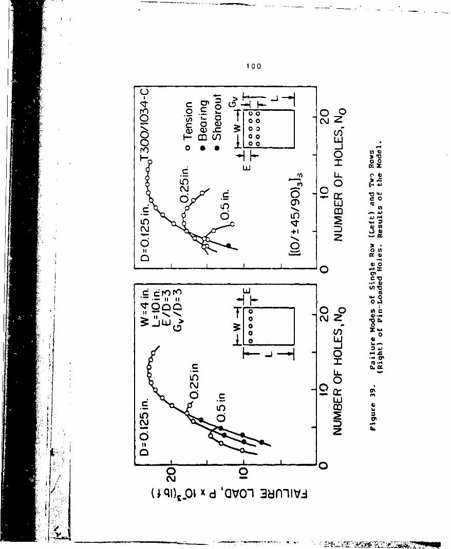
100
u-
r4 o r n0o$ 1001L
0 V00 a) 0 L
_ 00
L~Ld
9yh LU0 EU) v
N +1
c0
P- V
4H 00
00
uLitc)N 06
(iqlt lX d 'GO'O1 3dflhiiv

SECTION X
SUMMARY AND CONCLUSIONS
The following major tasks were completed during the
course of this investigation:
a) A model and a computer code were developed which can be
used in the design of mechanically-fastened composite
joints involving fiber reinforced laminates. The model
can be used to determine the failure loads and failure
modes of laminates containing a single pin-loaded hole,
two pin-loaded holes in parallel, and two pin-loaded
holes in series.
b) Experimental procedures were developed to determine the
characteristic lengths.
c) Tests were performed to determine the values of the rail-
shear strength and the characteristic lengths of Fiberite
T300/1034-C composites, and to evaluate the effects of
geometry and laminate lay up on these parameters.
d) A series of tests was performed measuring the failure
strengths and failure modes of Fiberite T300/1034-C
laminates containing a single-pin loaded hole, two pin-
loaded holes in parallel, and two pin-loaded holes in
series.
101
4_f

102
e) Comparisons were made between the data and the results of
the model. Good agreements were found between the
analytical 7na the experimental results.
f) Procedures were developed for the design of composite
laminates containing one, two, or more pin-loaded holes.
The model was developed on the basis of the following
assumptions: a) classical, two-dimensional laminate plate
theory, and b) linear relationship between the stresses and
strains. Good agreements between the results of the model
and the data suggest that these assumptions are reasonable
for a wide range of problems. Three dimensional stress
distributions and nonlinear stress-strain relationships
could be incorporated into the model in the future.
pp
If¼!i +

REFERENCES
1. J.P. Waszczak and T7. (. use, "Failure Hcde andStrength Predictict-; c.. Anisotropic Holt BearingSpecimens," J. of (rimposite Materials, Vol. 5, 1971,pp. 421 45.
2. D.W. Oplinger 4,i D.R. Gandhi, "Stresses inMechanicall,1 -stened Orthotropic Laminates,"Proceedinc':. of the 2nd Conference on Fibz-ous Compositesin Flight viehicle D~esign, May 1974, pp.813-834.
3. D.W. -~...Linger and D.R. Gandhi, "Analytical Studies of!;tr;,.,-ural Pe~rformance in Mechanically Fastened Fiber-JHeinfor-ed Plates," in Proceedings of the ArmySy4, osaiuat on Solid Mechanics, 1974: The Role ofMechanicei In Design-Structural Joints, Army Materialsand Mechani:s Research Center, 1974, AMMRC MS 74-'8,pp.2 11-242.
4. B.L. Agarwal, *Static Strength Prediction of BoltedJoint in Composite Material," AIAA Journal, Vol. Is,1980, pp. 1345-1375.
5. S.R. Soni, "Filure Analysis of Composite Larninateswith a Fastener Hole."3. oi Coinvosite Materials, 1981,pp. 145-164.
6. S.P. Garbo and J.M. Ogonowski, "ffet~c of Varýiances andManufacturing Tolerancies on the Dlesign Strength andLife of Mechanically Fastened Composite Joints,* FlightDynamics Laboratory, Air F'orce Wright AeroauticalLaboratories, T1echnical Peport AFAL-'TA-8-304, A
* 1981.
7. J.L. York, D.W. Wili-,on, andi R.fl. Pipes,uAnalysis. OfTension Failure Mode in Composite Bolted Jointxe~,3. ot Reinforced Plastics and Co=. sires. Vol. 1, 1982,
8. D.W. Wilson and R.fl. Pipos, "Analysis of the ShearoutFailure Mode in Composite Balted Joints,* Proceedingsof the 1st Inteiknational Conierence on CompositeStructure, Paisley College of Technology, Scotland.1981, pp. 34-49.
9. qA. C-ý11ings, 'Oq Z* Barin; stength ot Cr~pLamintes. joses, Vol. 13, 1982. pp, 242-252.
103
:L

104REFERENCES (Cont'd)
10. C.M.S. Wong and F.L. Matthews, " A Finite ElementAnalysis of Single and Two-Hole Bolted Joints in FibreReinforced Plastic," J. of Composite Materials,Vol. 16, 1982, pp.481-491.
11. N,J. Pagano, R.B. Pipes, "The Influence of StackingSequence on Laminate Strength," J. of CompositeMaterials, 1971, pp.50-57.
12. W.J. Quinn and F.L. Matthews, "The Effect of StackingSequence on the Pin-Bearing Strength in Glass FibreReinforced Plastic,' J. of Composite Materials,Vol. 11, 1977, pp. 139-145.
13., J.M. Whitney and R.Y. Kim, "Effect of Stacking Sequenceon the Notched Strength of Laminated Composites,"Composite Materials: Testing and Design (FourthConference), ASTM STP 617, 1977, pp 229-242.
14. I.M. Daniel, R.E. Rowlands, and J.B. Whiteside,"Effects of Material and Stacking Sequence on the
Behavior of Composite Plates With Holes," ExperimentalMechanics, 1974. pp. 1-9.
15. E.F. Rybicke and D.W. Schmueser, "Effect of Stackingand Lay-Up Angle on Free Edge Stresses Around a Hole ina Laminated Plate Uader Tension," J. of Composite.4atrrials, Vol. 12, 1978, pp. 300-313.
16. T.A. Collings,"The Strength of Bolted Joints inMulti-Directional CFRP Laminates," British RoyalkAicraft Establishment, TR 75127, 1975.
"17. J.H. Stockdale and F.L. Matthevs,"The Effect ofClamping Pressure on Bolt Bearing Loads in GlassFibre Reinforced Plastic5," Composites, Vol. 7, 1976,pp.34-38.
"18. Y.C. Fung, Foundations of Solid Mechanics, Prentice-Hall. Inc. Fn9Nv6"O M~iffs New eriiey, 1965.
19. R.M. Jones. Mechanics of Composite Materials, ScriptaI Book C pny, wihington, D.C. 1975.
20. T.L. Wilkinson, R.E. Rowlands and R.D. Cook. "Anincremental Finite Element Determination o! Stresses
S ': • Around Loaded Holes in Wood Plates.,.%nd Structures, 1961, Vol 1•, pp. 1232TaB'
,. t1. C.-S. Hong. "Stresses Around Pin-Loaded Hole in finiteOrthotropic Laminates," Transactions of the JapanSociety for Composite Materials. Trans. JSCM,0 Vol. 6,1960. pp. 50-55.
T=
i :
,:.4..
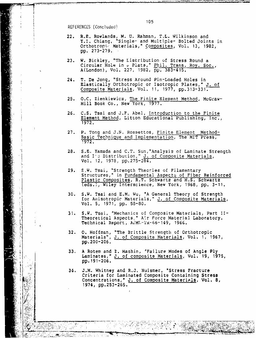
105REFERENCES (Concluded)
22. R.E. Rowlands, M. U. Rahman, T.L. Wilkinson andY.I. Chiang, "Single- and Multiple- Bolted Joints inOrthotroli, Materials," Composites, Vol. 13, 1982,pp. 273-279.
23. W. Bickley, "The Listribution of Stress Round aCircular Hole in v Plate," Phil. Trans. Roy. Soc.,A(London), Vol. 227, 1982, pp. 383-415.
24. T. De Jong, "Stress Around Pin-Loaded Holes inElastically Orthotropic or Isotropic Plates," J. ofComposite Materials, Vol. 11, 1977, pp.313-331.
25. O.C. Zienkiewicz, The Finite Element Method, McGraw-Hill Book Co., New York, 1977.
26. C.S. Tsai and J.F. Abel, Introduction to the FiniteElement Method, Litton Educational Publishing, Inc.,1972.
27. P. Tong and J.N. Rossettos, Finite Element Method-Basic Technique and Implementation, The MIT Press,1972.
28. S.E. Yamada and C.T. Sun,"Analysis of Laminate Strengthand If;; Distribution," J. of Composite Materials,Vol. 12, 1978, pp.275-284.
29. S.W. Tsai, "Strength Theories of FilamentaryStructures," in Fundamental Aspects of Fiber ReinforcedPlastic Composites, R.T. Schwartz and H.S. Schwartz(eds.), Wiley Interscience, New York, 1968, pp. 3-11.
; 30. S.W. Tsai and E.M. Wu, "A General Theory of Strengthfor Aisotropic' Materials," J. of Composite Materials,
1 Vol. 5, 1971, pp. 58-80.
31. S.W. Tsai, "Mechanics of Composite Materials, Part II-Theoretical Aspects," A.r Force Material Laboratory.Technical Report, A:Mr,-T.R-66-149, 1966.
32. 0. Hoffman, "The Brittle Strength of OrthotropicMaterials", J. of Composite Materials, Vol. 1, 1967,pp.200-206.
33. A Rotem and Z. Hashin, 'Failure Modes of Angle PlyLaminates," J. of composite Materials, Vol. 19, 1975,pp. 191-206.
34. J.M. Whitney and R.J. Nuismer, "Stress FractureCriteria for Laminated Composite Containing StressConcentrations," J. of Composite Materipls, Vol. 8,1974, pp.253-265.
l'i. + ,. ++ .-, - -- - ._ . . . . .. . . -.. --- '• ,77-7 *

REFERENCES (Cont'd) 106
35. R.J. Nuismer and J.M. Whitney, "Uniaxial Failure ofComposite Laminates Containing Stress Concentrations,"Fracture Mechanics of Compo-ites, ASTM STP 593, 1975,pp. 117-142.
36. R.J. Nuismer and J.D. Labor, "Applications of theAverage Stress Failure Criterion: Part I-Tension," J.of Composite Materials, Vol. 12, 1978, pp.238-249.
37. R.J. Nuismer and J.D. Labor, "Applications of theAverage Stress Failure Criterion: Part II-Compression," J. of Composite Materials, Vol. 13, 1979,pp. 49-60.
38. S. Timoshenko, and S. Woinowsky-Krieger, Theory ofPlates and Shells, McGraw-Hill, New York, 1940.
39. S.G. Lekhnitskii, Anisotropic Plates, (translated fromthe second Russian Edition by S.W. Tsai and T. Cheron),Gordon and Breach Science Publisher, Inc., New York,1968.
40. J.M. Whitney, D.L. Stansbarger and H.B. Howell,"Analysis of the Rail Shear Test- Applications and
Limitations," J. of Composite Materials, Vol.5, 1971,pp.24-34.
41. R. Garcia, T.A. Weisshaar and R.R. McWithey, "AnExperimental and Analytical Investigation of the Rail-test Method as Applied to Composite Materials,"Experimental Mechanics, Vol. 20, pp. 273-279.
42. L.T. Hart-Smith, "Bolted Joints in Graphite-EpoxyComposites," NASA-CR-144899.
43. Private Communication, Fiberite Company, Winona,Minnesota 55987.
/1
'I

',-V
APPENDIX A
The Transformed Reduced Stiffness Matrix Qij
•: x 1
The components of the matrix QPi appearing in Eq. (12) are
O, 1 1 I PCos 4+2 (QP 1 2 +2QP 6 6 )sin 2+Q P2 2 sin 41P 2=(QP +QP22- 4QP66 sin 2rcos2O +QP1 2 (sin 4I+cOS 4i)
Q 2 2 QP I1sin4 +2 (QP .+2QP 6 6 )sin2 cos2S +QPcos 4Q? P -P 3Q3 ) siPco3• 3QP13(Q 11 Q 1 2- )sinlcos71+(Q12-QP22+2QP33 )sin3TcoOsT
O P (QP QP - 2 Q P )sin3ncOsy+(Q1 2 -QP2 2 +2QP )sinncos3n
P (QP +QP2 QP -2Q 3 3 )sin cos2r,+QP (4si n+cos )33(si22- 12C33 33
* , in which
P 12 (up 1 2 EP 2 )/(0"UP 1 2 UP 2 1 1 /(1 12P 21lP -P )!! •P2~2 " P/l•12UP21)
4' P
31 1

V 108
The superscript p denotes the material properties of the
p-th ply, and the angle -n is measured from the xias to
the x-axis. 2~ 12a
transverse, and shear moduli of the p-th ply, respectively.
P 1 and V 2 1 are Poisson's ratios for the p-th ply and
satisfy the relation
Pi 12/E P1 2 /P2
.......

109
APPENDIX B
The Coordinate Transformation matrixT
xl
Cos 2 1sin 21 2sinricosri
[T) 1 n TI CS T1 -2sinncosin
-sinnrcosTn s inricosj Cos T-sin '
The angle n~ is measured from the x-ai cth xais
+t\1
..........~iA*

S110
APPENDIX C
The Finite Element Mesh Generator
II The mesh generator generates 306 quadrilateral elements
for a single hole, and 612 and 655 elements for two holes in
parallel and two holes in series, respectively. To controlI costs, this number was held fixed (the reader should note
that 612 elements involve a matrix of size 1400 x 300). The
mesh is designed in such way that the characteristic curve
can be encompassed by a square of size 2z x 2z, in which a
fine mesh was generated and outside of which the calculated
stresses are still reasonably accurate (see Figures 5, 6,
7). A suitable value of z for a given geometry has to be
determined before calculating the stresses. Mathematically,
this problem may be stated :
Optimize z
subject to ( Rc + D/2 ) S z S W/2 (C.1)
z s:E (C.2)
Equation (C.1) can be rewritten as
0 R ( z - D- f/2 ) S ( W/2 - R- D/2 ) (C.3)i i
Assume that E is large enough that eq.(C.2) is always
satisfied. Assume that z/D is a function of W/D and R /Do'~ /

111
and can be expressed by
z/D - f( W/2D- Rc/D -1/2 ) f( ý/D ) (C.4)
where ý/D u W/2D - R /D - 1/2 and t is some unknown
c
function.
Assume that z/D is a second order polynomial function of
4/D. Then eq.(C.4) can be written as
z/D * a(4/D) 2 + b(ý/D) + c (C.5)
This equation reflects the general trend that as W, and
hence 4, increases, z must be made bigger, since the total
number of *.lements is constant. Three conditions are
necessary to determine the constants, a, b, and c.
When W/2 R + D/2 ( =0 ), then the only choice of z
is
z/D -R /D ÷ 1/2 W w/2 (C.6)c
Substituting eq.(C.6) into (C.5), gives
v 2300
c - R /D * 1/2 (C.7)c
When W changes from Wl to W2, say, 4 changes by the
* . amount C 2 - (. The writer has found from
computational experience that the following changes in z
~Amt,/''
!--,,• = : _ - : ÷ ___• • :. "-- •'- • ..... . .. ... ... : ,- . ...: .... .... - - •" -,• - • ---- •i -..----. 7 • - -
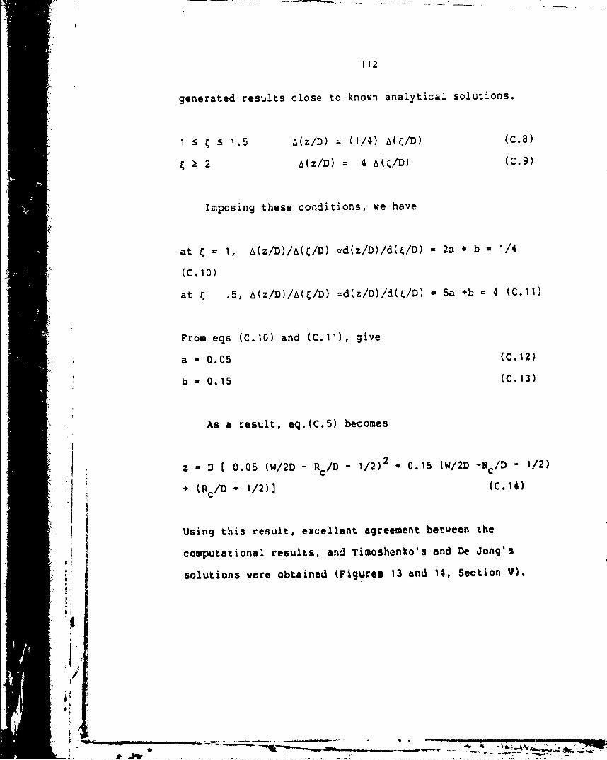
112
generated results close to known analytical solutions.
1 : :5 1.5 A(z/D) (1/4) A(ý/D) (C.8)
Ž 2 A(z/D) 4 A(C/D) (C.9)
Imposing these cotiditions, we have
at 1 1, A(z/D)/A(t/D) =d(z/D)/d(t/D) - 2a + b 1/4
(C. 10)
at • .5, A(z/D)/L((/D) =d(z/D)/d(C/D) = 5a +b 4 (C.11)
From eqs (C.10) and (C.11), give
a - 0.05 (C.12)
b * 0.15 (C.13)
As a result, eq.(C.5) becomes
z - D [ 0.05 (W/2D - RC/D - 1/2)2 * 0.15 (W/2D -Rc/D - 1/2)
(Rc/D + 1/2)1 (C.14)
Using this result, excellent agreement between the
computational results, and Timoshenko's and De Jong's
* solutions were obtained (Figures 13 and 14, Section V).
AI
/1
h.

113
Appendix D
Shape Function Used in the Finite Element Code
In the isoparametric element, the geometry and the
displacement of the element are described in terms of the
shape function N , by a transformation from a mz.ster element
in the r-s coordinate system to the element in the z -x2
coordinate system (Figure 40).
X. N (y,s) ii= i=1,2
ui Na (Ys) qic a=1,2,3.or 4
N(r,s)-l/4(1+rr )(tss ) -Sr, sS I
Here xi, is the coordinate of node a in the i-direction, qi,
is the displacement of node o in the i-direction, and r and
sacre the coordinates of node a referred to the master
element. Note the property
1, if ae
N (rsB) -
L 0, if a$B
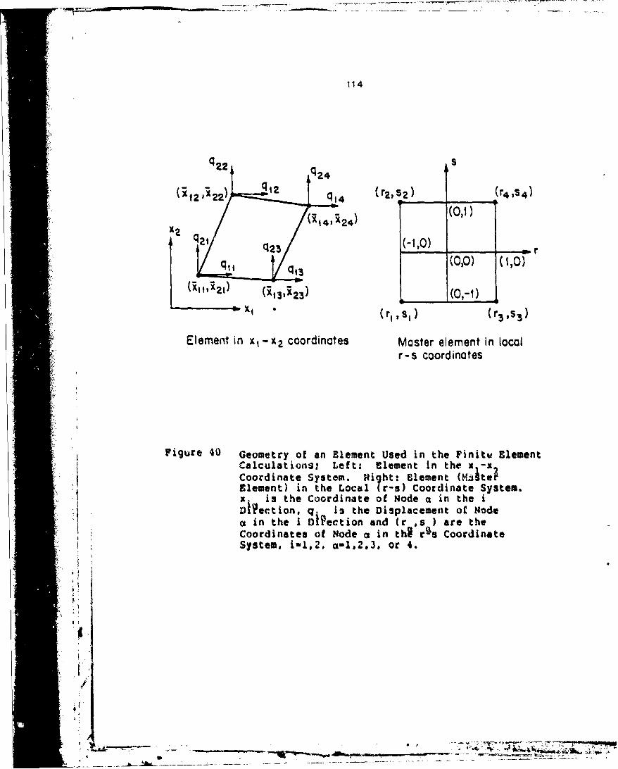
114
qq U2, S2 (r4 , s4)
(011)
q2 /(-1,o)2-2 r
q q (0,0) (1,0)
(•,•'z) (•,,,____ (0,-1)
X, (r,,s ) (r 3 ,s 3 )
Element in xt-x 2 coordinates Master element in localr-s coordinates
Figure 40 Geometry of an Element Used in the Finite ElementCalculations; Left: Element in the x -x
Coordinate System. Right: Element (Nato?Element) in the Local (r-s) Coordinate System.X. is the Coordinate of Node o in the iDI~ection, q. is the Displacement of Nodeca In the i DIiection and (r ,s ) are theCoordinates of Node a in tho r s CoordinateSystem. i-1,2, a-1,2,3, or 4.
S--"-

115
2 APPENDIX E
7 Listing of a Sample of Input-Output of the Computer Code
1,, 4 1.
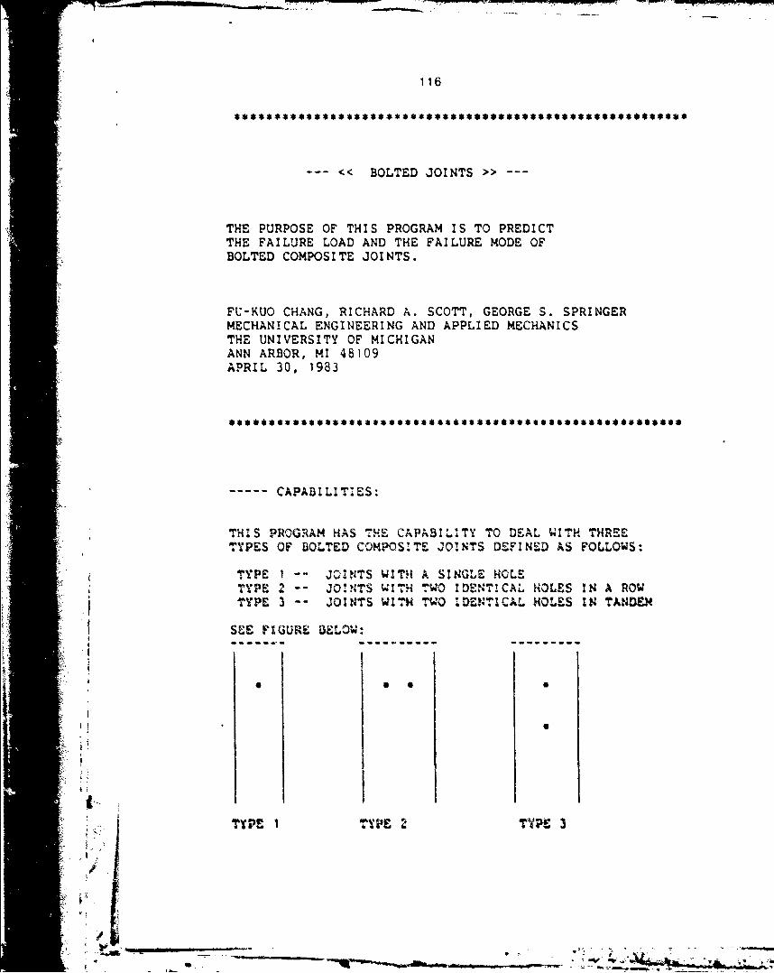
116
"<< BOLTED JOINTS >>
THE PURPOSE OF THIS PROGRAM IS TO PREDICTTHE FAILURE LOAD AND THE FAILURE MODE OFBOLTED COMPOSITE JOINTS.
FU-KUO CHANG, RICHARD A. SCOTT, GEORGE S. SPRINGERMECHANICAL ENGINEERING AND APPLIED MECHANICSTHE UNIVERSITY OF MICHIGANANN ARBOR, MI 48109APRIL 30, 1983
*emme**e$$wss•$..eue msee se e55ee smssesseessessi~sm•eees$es
CAPABILITIES:
THIS PROGRAM HAS THE CAPABILITY TO DEAL WITH THREETYPES OF BOLTED COMPOS'.TE JOINTS DEFINED AS FOLLOWS:
TYPE I -- JOINTS WITH A SINGLE HOLETYPE 2 -- JOINTS WITH TWO IDENTICAL HOLES IN A ROWTYPE 3 -- JOINTS WITH TWO IDENTICAL HOLES ZN TANDEM
SZE FIGURE BELOW:
--------------- ----------------
TYPE I TYPE 2 T YPE 3
/
/€-

It 1 17
THIS PROGRAM CAN ALSO HANDLE THE FOLLOWINGLOADING CONDITIONS:(A). PIN OR PINS CARRY ALL THE APPLIED LOAD.(3). PIN OR PINS CARRY ONLY A FRACTION OF THE TOTAL
LOAD APPLIED AT THE BOTTOM OF THE JOINT. THEREST OF THE LOAD IS CARRIED BY THE UPPER END.
SEE FIGURE BELOW:
P2
/P=P+P2, P>P1 AND P>P2 OR P-Pl
P: THE APPLIED LOADPl:LOAD CARRIED BY THE PIN (PINS)P2:BY-PASSED LOAD
P
tFOR EACH TYPE OF JONI. TH:S PROGRAM CAN HqOLE
THE FOLLOWING SITUAT!ONS:SI
(A). DIFFERENT PLY OR:NATICZNS(BW. DFFERENT MATERIAL PROPER'4£S (SYNMETRtC LAMINATE)•(). DIFFERENT GEGMETRICAL CONF GURATIONS INCLUDIG
DIFFERENT HOLE SIES, HOLE POS3T:S, JOINTThCKNESSES, AND JOINT LENQTHS.
E PROGRAM !S BASED ON VIE FOLLZOING ASSUM"ZONS:(1). A UNr1MOR TENLSILE LOAD 4S APP&AIE SYML'RICALZJ
WT.HS RESPE•1T' TO VIE CENTELa`NZC OF THE PLATE.(2). Th LM:fl IS S aTRZC,
S.-

"(3). HOLE SIZES ARE EQUAL IN EACH JOINT WITH TWO HOLE(4). PIN IS RIGID. THE PIN SUPPORT IS ALSO RIGID.
-------- ANALYSIS:
THE STRESSES ARE CALCULATED USING A FINITE ELEMENT METHODFORMULATED ON THE BASIS OF TWO DIMENSIONAL CLASSICALLAMINATION PLATE THEORY. THE FAILURE LOAD AND FAILUREMODE ARE CALCULATED USING THE CHANG-SCOTT-SPRINGER FAILUREHYPOTHESIS TOGETHER WITH THE YAMADA-SUN FAILURE CRITERION
---- INPUT INSTRUCTIONS
***'* ENTER MATERIAL PROPERTIES *..
DO YOU WANT TO USE GRAPHITE/EPOXY T300/1034-C?ENTER YES OR NOyes
MATERIAL PROPERTIES OF T300/1034-C
LONGITUDINAL YOUNGS MODULUS: 21300000.00000 PSITRANSVERSE YOUNGS MODULUS: 1700000.00000 PSISHEAR MODULUS: 897000.00000 PSIPOISSON RAT!O: 0.30000LONGITUDINAL TENSILE STRENGTH: 251000.00000 PSILONGITUDINAL COMPRESSIVE STRENGTH: 400000.00000 PSILAMINATE SHEAR STRENGTH: 19400.00000 PSICHARACTERISTIC LENGTH (TENSION): 0.0180 INCH
CHARACTERISTIC LENGTH(COMPRESSION4): 0.0700 INCH
-~.-------- ------------------
JOINT TYPE SELECTZON
TYPE f : JOINT WIrH A SZNGLE HOLETYPE 2 : JOINT WITH TWO HOLES !N ROWTYPE 3 : JO:NT WITH TWO HOLES IN TAND4E
4 WMICH TYPS OF JOINT DO TOU WANT TO SELECT?
ENI&AER I.. OR 3.
4 I
I , , m • i " ' . . . - r: m "•,, -

I119
�DO YOU CONSIDER A BY-PASS LOAD?
ENTER YES OR NO
no
THE FOLLOWING GEOMETRIC PARAMTERS MUST BE SPECIFIED:
(A) DIAMETER OF THE HOLE, D(D SHOULD BE LESS THAN 1 INCH FOR DEPENDABLE RESULTS)
(B) WIDTH OF THE JOINT, W(C) LENGTH OF THE JOINT, L(D) EDGE DISTANCE OF THE JOINT, E(E) DISTANCE BETWEEN THE CENTERS OF
TWO HOLES, S
SEE FIGURE BELOW:
I-. w -�
I-S-I I I* -
S* -
j � THE DIAMETER MUST BE WPUTED IN INCHES, THE OTHERGEOMETRIC PARAMETERS MAY BE EITHER IN INCHESOR AS A RATIO TO DIAMETER (PARAMETER! DIAMETER)
ENTER THE HOLE DIAMETER IN INCHES
0.25
DO YOU WISH TO ENTER ALL G�OMETR!C PARA?4�TERSIN TERMS OF DIAMETER RATiC� (PARAMETER/DIAMETER) ?ENTER YES OR NO
''Iy
ENTER THE WIDTH TO DIAMETER RATiO;
8
� /
I- *--- . - __ �

120
ENTER THE EDGE TO DIAMETER RATIO:
3
ENTER THE LENGTH TO DIAMETER RATIO:
20
INPUT THE JOINT THICKNESS AND THE PLY ORIENTATIONS(SYMMTRIC LAMINATE ONLY)THE PLY ORIENTATION AND THE NUMBERS OF PLIES IN THEPLY GROUP HAVE TO BE SPECIFIED.
*1. THE PLY GROUP IS DEFINED AS A GROUP OF PLIESHAVING THE SAME PLY ORIENTXATION.
*2. EACH PLY ORIENTATION IS MEASURED FROM THELOADING DIRECTION TO THE FIBER DIRECTION.THE ANGLE IS POSITIVE CL~OCKWISE ANDNEGATIVE COUNTJ.ERCLOCKWI SE
SEE F'IGURE BELOW
ANGLE/
*HOLE
ENTER THE JOINT THICKNESS IN INCHES
2 0.125
ENTE~R THE TOTAL NUMBER OF PL~Y GROQUPS.O.THE NAXIMUM NUMBER OF '7HE PLY GROUPS 100
INPUT AN INTGE.R
II 4C~NTER WhE PLY ORI ZNTA'?I ON OF EACH PLY GROUP
F.NTER THE PLY ORIENTATION OF PLY GROUP I
*Pa

•:, 121
IN DEGREES
0
ENTER THE NUMBER OF PLIES IN PLY GROUP T IN INTEGER
6
ENTER THE PLY ORIENTATION OF PLY GROUP 2IN DEGREES
45
.r.ENTER THE KNMBER OF PLIE~S I N PLY GROUP 2 I N I NTEGER
6
ENTER THE PLY ORIENTATION OF PLY GROUP 3IN DEGREES
ENTER THE NUMBER OF PLIES ItN PLY GROUP 3 IN INTEGER
6
ENTER THE PLY ORIENTATION OF PLY GACOU 4VIN DEGREES
90
ENTER THE NUMBER OF PLIES IN PLY GR')UP 4 !N INTEGER
64
VC' YOU W~AN-T TO AAVE A LIST OF THE 18MU D)At$ 7WERT) YES OR NO
LIST OF DATA
k ; JJl NT TYPE SiLCTgON' 1:. ~. LOAD TYPE SE. TI41.: 0.0 1 OF BYPASSWD
": GEOMETRY s ( INCES)
I DZ! ETER V I rTH EweG THtCKN£SS LLNGTH
0.2500 2.OCOO 0.?500 .0.1250 5.0000
i

A• 12 2
< GROUP ORIENTATI ON >:
TOTAL PLY GROUP NO.- 4
GROUP 1 ORIENTATION= 0.0 THICKNESS= 0.03125 INCH
GROUP 2 ORIENTATION= 45.000 THICKNESS= 0.03125 INCH
GROUP 3 ORIENTATION=-45.000 THICKNESS- 0.03125 INCH
GROUP 4 ORIENTATIONa 90.000 THICKNESS- 0.03125 INCH
< MATERIAL PROPERTIES >
LONGITUDINAL YOUNGS MODULUS : 21300000.00000 PSITRANSVERSE YOUNGS MODULUS : 1700000.00000 PSISHEAR MODULUS: 897000.00000 PSI
2 POISSON RATIO: 0.30000LONGITUDINAL TENSILE STRENGTH: 251000.00000 PSILONGITUDINAL COMPRESSIVE STRENGTH: 200000.00000 PSILAMINATE SHEAR STRENGTH: 19400.00000 PSI
CHARACTERISTIC LENGTH (TENSI'ON): 0.0180 INCH"CHARACTERISTIC LENGTH(COMPRESSION): 0.0700 INCH
DO YOU WANT TO MAKE ANY CHANCE IN YOUR DATA?ENTER YES OR O0
c TH E .ISAENGTH PREDICTION OF FASTENED COMPOSITE JOINTS
-------------------------- ----------------1
--------.... L ST OF INPUT --------
JONT TYP SELECTION OSLOAD TYI: SELECTI ON: 0.0 X OF BY-PASSED LOAD
* c GEOMETRY - (INCHES)4"Nw ANTE1R WI UTH EZE 1?11 CKNE4SS LENGTH
0.2500 2.0000 0.'500 0.-1250 5.0000
8'K

123
< GROUP ORIENTATION >TOTAL PLY GROUP NO.= 4
GROUP 1 ORIENTATION= 0.0 THICKNESS= 0.03125 INCH
GROUP 2 ORIENTATION- 45.000 THICKNESS- 0.03125 INCH
GROUP 3 ORIENTATIONE-45.000 THICKNESS- 0.03125 INCH
GROUP 4 ORIENTATION- 90.000 THICKNESS- 0.03125 INCH
MATERIAL PROPERTIES:
LONGITUDINAL YOUNGS MODULUS: 21300000.00000 PSITR~ANSVERSE YOUJNGS MODULUS: 1700000.00000 PSISHEAR MODV.US: 897000.00000 PSIPOISSON RATIO,* 0. 30000LONGITUDINAL TENSILE STRENGTH: 251000.00000 PSILONGITUDINAL COMPRESSIVE STRENGTH: 200000.00000 PSILAMINATE SH~EAR STRENGTH: 19400.00000 PSI
CHARACTERISTIC LENGTH (TENSION): 0.0180 INlCHCHARACTERISTIC ZLENGTH(COMPRESSON). 0.0700 INCH
-------- LIST OF OUTPUT -----
< FAILURE L0AD AND FAILURE MODE >
I krTE MAXIMUM4 LOAD (P ).3012.7 La
THM BEARING STRENGTH( P/(DONS) )s 96406.5 PSI(H "H LAMI NATE THICKNESS)
N4E ?A ILURE XWODE :BEAR ING MODE. AT THE ANGLE 8. 43?7 DEGREE
THE FAILURE ANGLE IS W~INEDJ IN THE FOLLOWINMG FIGW.Er

124
ANGLE/ \ /
\ //O* ,
/ HOLE
HOLE
* THE INITIAL FAILED PLY GROUP (AT THE MAXIMUM LOAD) -THE PLY ORIENTATION OF THIS PLY GROUP- 0.0
DO YOU WANT TO RUN THE PROGRAM AGAIN?ENTER YES OR NO
y
DO YOU WANT TO MAKE ANY CHANGE IN YOUR DATA?
ENTER YES OR NO
WHICH PART OF THE DATA DO YOU WANT TO CHANGE ?"(1). JOINT TYPE AND GEOMETRY.
4 (2). PLY ORIENTATION.(3). MATERIAL PROPERTIES.
ENTER 1,,2.OR 3.
JOINT TYPE SELECTION
TYPE 1 : JOINT WITH A SINGLE HOLETYPE 2 : JOINT WITH '""WO HOLES IN ROWTYPE 3 : JOINT WITH T4O HOLES IN TANM
WHICH TYPE OF JOINT DO YOU WANT TO SELECT?
ENTER 1, 2. OR 3.
;7.",

125
3
DO YOU CONSIDER A BY-PASS LOAD?
ENTER YES OR NO
n
THE FOLLOWING GEOMETRIC PARAMTERS MUST BE SPECIFIED:
(A) DIAMETER OF THE HOLE, D(D SHOULD BE LESS THAN 1 INCH FOR DEPENDABLE RESULTS)
(B) WIDTH OF THE JOINT, W(C) LENGTH OF THE JOINT, L(D) EDGE DISTANCE OF THE JOINT, E(E) DISTANCE BETWEEN THE CENTERS OF
TWO HOLES, S
SEE FIGURE BELOW:
I- wW
E-- S -I I iS -
SL -
1;
"THE DIAMETER MUST BE INPUT-ED IN !.NCHES, THE OTHERGEOMETRIC PARAMETERS K"%Y BE EITHER IN !NCHESOR AS A RATIO TO ixiAmEPlF4 (PkARAETER/ DIAMETER)
ENTER THE 14OLE U! Ab•-. ER I N I NCHES
0.25
DO YOU WIS;4 TO ENTER ALL GEOMETRIC PARAMETERSIN TERMS )F DIAMETER RATIO (PARAMETER/DIAMETER) ?ENTER YW,'; OR NO
--- . . " _ , - -- ' . .. ,,

126
ENTER THE WIDTH TO DIAMETER RATIO:
8
ENTER THE EDGE TO DIAMETER RATIO:
3
ENTER THE LENGTH TO DIAMETER RATIO:
20
ENTER THE TWO HOLE DISTANCE TO DIAMETER RATIO:
3
DO YOU WANT TO HAVE A LIST OF THE INPUT DATA ?ENTER YES OR NO
n
< THE STRENGTH PREDICTION OF FASTENED COMPOSITE ;]OITS
- LIST OF INPUT
JOINT TYPE SELECTION- 3LOAD TYPE SELECTION: 0.0 % OF BY-PASSED LOAD
GEOMETRY > : (INCHES)DIAMETER WIDTH EDGE THICKNESS LENGTH
0.2500 2.0000 0.7500 0.1250 5.0000
DISTANCE BETWEEN THE TWO HOLES (INCHES)
0.7500
SGROUP ORIENTATION :TOTAL PLY GROUP NO.- 4
GROUP I ORIENTATION* C.0 THICKNESS- 0.03125 INCH
GROUP 2 ORIENTATION* 45.000 THICKNESS* 0.03125 INCH
GROUP 3 ORIENTATION,-45.000 THICKNESS- 0.03125 INCH
/
I* i

127
GROUP 4 ORIENTATION- 90.000 THICKNESS= 0.03125 INCH
MATERIAL PROPERTIES:
LONGITUDINAL YOUNGS MODULUS: 21300000.00000 PSITRANSVERSE YOUNGS MODULUS: 1700000.00000 PSISHEAR MODULUS: 897000.00000 PSIPOISSON RATIO: 0.30000LONGITUDINAL TENSILE STRENGTH: 251000.00000 PSILONGITUDINAL COMPRESSIVE STRENGTH: 200000.00000 PSILAMINATE SHEAR STRENGTH: 19400.00000 PSI
CHARACTERISTIC LENGTH (TENSION): 0.0180 INCHCHARACTERISTIC LENGTH(COMPRESSION): 0.0700 INCH
------ LIST OF OUTPUT
"<AILURE LOAD AND FAILURE MODE >
THE MAXIMUM LOAD ( P ), 5346.7 LB
THE BEARING STRENGTH( P/(D*H) )- 171093.2 PSI(H : THE LAMINATE THICKNESS)
THE FAILURE MODE w SHEAROUT MODE, AT THE ANGLE 47.812DEGREE
THE FAILURE ANGLE IS DEFINED IN THE POL.LOWING FIGURE
----------------------------------------------------------------1' \*ANGLE
-1•/ HoLE
LHOLE
I II "
/
: " ~~~~~~~~~~~......................................" ' -............. •-:• ..... •.... .....

128
* THE INITIAL FAILED PLY GROUP (AT THE MAXIMIUM LOAD) 2THE PLY ORIENTATION OF THIS PLY GROUP= 45.000
*.e THE FAILURE INITIATED FROM THE BOTTOM HOLE
LOAD CARRIED BY THE TOP PIN = 2028.644466 LBLOAD CARRIED BY THE BOTTOM PIN , 3318.018795 LB
-------------------------------------------------
DO YOU WANT TO RUN THE PROGRAM AGAIN?ENTER YES OR NO
no#Execut ion terminated
I
/
t.
-A
b. . .. >'- • '' .- a..- ' ,, -- ,.•. ,-- "...... .... .. " -" " aZL

AMR
129
APPENDIX F
Summary of Data for Calculating RI andH
This Appendix contains the data which were generated to
determine the rail shear strength S and the characteristic
lengths R t and R Cfor Fiberite T300/1034-C graphite epoxy
laminates.
N4otations used in Tables 6-14
D hole diameter (in)
W specimen width (in)
L. specimen length (in)
H4 spetcimen thickness (in)
edge distance (in)
P failure load under tension (lbf)
Pae average iailure load under tension (lbf)avggt
S rail shear s.rnt (psi)
Sav average r~ail shear strength (psi)
characteristic lengt~h in tension (in)
K. characteristic length inl compression (in)
4C
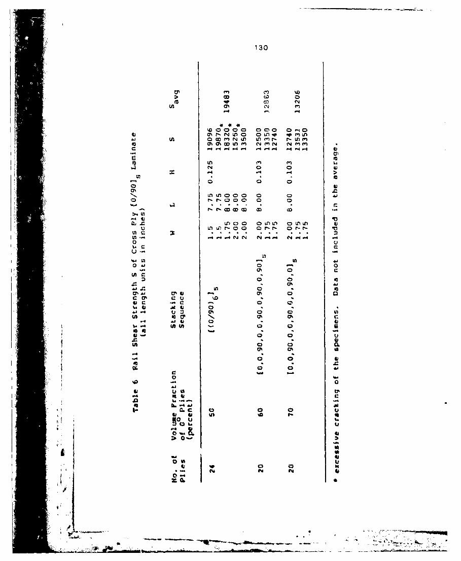
130
W 0
0%cc
L00000 00M0 0-000%*-NL0 OLA r, inMLA
F~C tOýfl ~ N, (
CD 0
0 1
0%60 0 0 03 0
v. wl
os u
00 003
0% 0
it0

131
0'0
ONN
0. 00Ln OD '-40 1 0 7 - m NM
-0 -4 Q1
C4
04~
000. 00 -AC k0.4 > 0* t t 6- ~V 0. momo-~ 1N O OO 0~
soo

132
co N
0 (N 0
c
C,'1
0000 0000 0000 0000
Q- 0. 'or- 00 ' r-Oc-4 r. 0 -NL U 1 %
cm -. 1-" n-0 r o%
fn f" f 0 0"
us 0
Gi n0 6 00C h 0 0
bfl 04 &
N ~~n f
aýýý .- AMR

133
0 -4 00
r- N 4
ELO
toi4
u~-u4. N N N (~ P44 44F-I C;
mmo DI W 0 w 0oc 0o
k N
94i
CD0

134
oo m
-P4
0z >
0o f s-e. CON 0J~J f (lf - O %
4' 44
~~0 0 0 k l l VL
-46 4s.)

* 135
.0 P-4
co o N
(N 0 N
o cCl
Gc M
-4+1IN
CDNo n o c o o o c o
U .b Ul0QU) ( 00Q r4t L lT
in If) tni4N NNN
0u 0 0c
~~U5iltf ~0000 OJ'@0 mommU00 0 9- -4 P- 9 94 0- V- 9 4 F4 V- F- 9 9 9 qP
0 0 0

'36
0 m N
(N0C N (N (NlI
mmt. ownm-w Cm -4-Nr- C - - -cc
.JO41
CO L
E- (
V, co
0 .M0 N N f N w N0C1-4 1-4 -- 4
N t
aladrl

137
o co Lo
Q C
P -4 N N in
COL
c oooc 0~fl0 o 000 0000 ooou*-rMMNM F, -4 P-4r w w w w v *N~ o m wv kn
*~- #.4J. D VU44 NNNN NNNN D'ý00'0 flU0Lf
v vv
a00
W) U 14f)ul U) 0 %IJD)o a o
I"d N ~

138
0 0 0 0
Nn
000 000 00 0 0
040
A4
AJu
o to
0N 000 000 0 000 r 0 0 000% 0.MO OVfl 000 00i n 0% % 0m
laC
IA U) LA I
(N (N N
C~C N .
01

139
APPENDIX G
Summary of Data for Loaded Holes
This Appendix contains the data vhich were generated
from Fiberite T300/1034-C graphite epoxy laminates
containing loaded holes. The Tables in this Appendix also
contain the failure strengths and failure modes calculated
by the present model for the conditions of the tests.
Notations used in Tables 15-29
D hole diameter (in)
W specimen width (in)
L specimen length (in)
H specimen thickness (in)
E edge distance (in)
GH distance between two parallel holes (in)
GV distance between two series holes (in)
P failure load under tension (lbf)
P average failure load under tension (1bf
Pa calculated failure load (lbf)
N experimental failure mode
Mc calculated failure mode
T tension failure mode
B bearing failure mede
S shearout failure mode
T• tearou& along !iber directionat t45

140
u Wnz IN.
E- E)
oncaON
U n
Now N N -N 0 0
00 F-4 A 4 N N N N N m Nf
th n
0
o 0n00 0 00 0 0 00 0 0
in n inLn r- P
N ocok

141
04-03
CAC
a'n
CP>0
CC
0 m q q 0 U) W
to(0) w 0)
(IQ
000 N 0NNC N0 0 000 0000
0 N
~~o% LALAv
CC

142
u
0)
) E-E -E- E -E-E -E0 E-E- C 90WW
0 'xt
40
00
0IO L N Ný r*-% Nmw otrý0 - - -- I N C4
U,'
U) U) L
P 4
Wa f1Nf t- r-l N NN
E-0000 a. U) U)C ý ,C
CC

143
EC-' E- -E E-4E-1 E- Er E E- Er- toF" ~E -r
c0-
La Cl% -4 -4% m o 0C Ow mcowm
F- 94 V-4 - m04 0. 4 - v4 N I
LCn
P-4 P" P
toOOC JO CC9 0 0 O
0- co kn ( * 3 0% 0 (1r4 Q0IQl0 0 M IXLn nr4-o % co&)Ut cchO w "Nfi n% 0 % A 4n 0
fo. ?I- w- 4s,4.4 . 4-4 NN N N
in f
"P '4 -4 IN"

144
4 ' E~- E- E- E- E-E- E- E- E- E-
1-4
N-0
0"N N Uf)
rd
U) 0to c N
C N .- 4oCIO -4 1-4N
(A U)000o 000 0000 0000M .0 0 Q0N - 0C)U CDm n mOenO
00W ) -4-N4v-4 CV.-.-. -4 NN
too - U) Ul)
-W4
m) up) U vsP) %
C.) 0D 00 I 0
oo U)
aA

145
63 E- E-
-4
U) U0 LOP-4 N N
-4-4PC1
0 N4ý V 0 N q l IC .
N 4') - U') 4l
o 4
U)l(M03t
ap -4 I

146
cm M M n MC OC -E -E Oc0r -o~
f- r,'
CC
• •D N
to a% o r•- co)
N N 4 ' M F
" 1 Lo
42.
0 NIkC " 0) 0'c o
", CN 6n .4'
-4• woo "F - w
•-.,+.

147
E-4~N, NI
0 ~ ~ ~ U '1,N JIII N I
0))
044
44 m) N N u)L a 0f-I
tn U') to
r-4.4
.744
0
000 00 0000000 f% - 0Q ~ r0 0 C~ 0 0N C 4 4 U4 N 04)00 4
o ~ ~ ~ i Ln In-,4~ .,4r,4 N N N ~N N
0oc oL"4 P4
7.~ 77If ) f

1A8
W E~%$. n E E-' t))U
CL
C6. Ný00 n k 0 mc op 0 L
IN ~ ~ lNNC l0 oVk - 2
COO 1 Nmw w 0N
f~lO~ oulo 0000 oooooU)k 0. &r.o voo 0in
-4 ~ NNN ~ ~kmi>0 il

149
E-0-E ~0E- ~E-E
0
0A m
-P4
0 00 000 N00CcU3C 0 0 N N
0. '4 4r4 ý .- -44 V- p 640-4 - 4 014 V. 40 .lO0
IV
0k
* 0 ý t0C,0 0 caC;4

1 60
0
r-4 E -E4E
U,
U) 0a ainQa0 aU 0rr- 0 (N" N 1-4N m (nN 43
0' -4 -
ell to qw- Utp. 00 0Ulf9 U 0
44,
""A

04
U0 000
M - a r -4 M o n0 '.0 ow0
0
)r
ee
4-A
fC n l0q
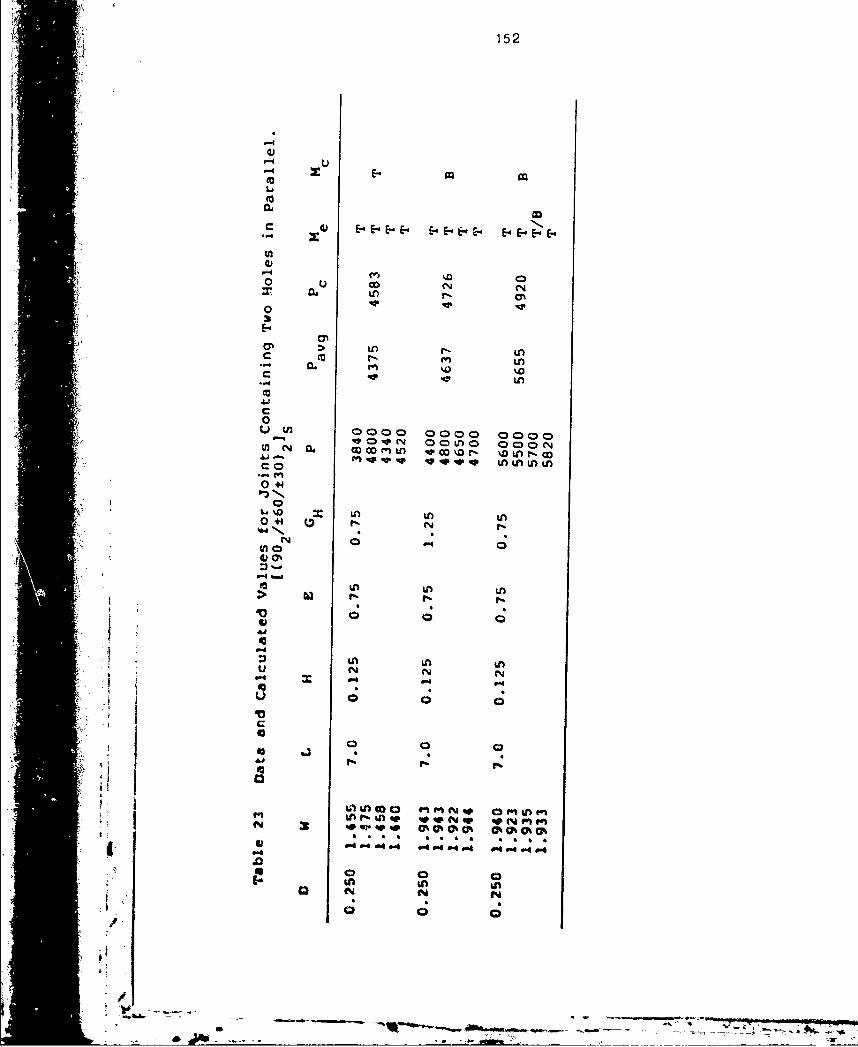
152
Lim
E- E- E-E-E E- E-e.E- E -. E -
312
a Ln
0
LAADt LA
'la
C k r
0000 0000 0m k000~04 W4OO 0 4 fl4 4 - 0-40404 0
40.

153
U)
Li C
4 O ULUL UUUU Ucuc
f-4 m (N N C% 4 ý4U 1-on 0. Ul) U') L nLn L w lL
ca
V iuli 0 0%%0 % oCha 0%
C (U N04U)U'

154
P-1P-4
a)
cnn-4
CO 0 40000
0
Ul)
0 +4
V 0 00 0
ko L
9.N

S~155
S E- E- E- E- E-
E- E- E- E- E-4 'E- ~E- E-0 -E E" E-Er'E- E-E- E-4E- E'E'E
Lin
E-~~ N( "OLn
m ) 000 U) Coc Co o 0 00 0 0kn 0 N Nn m ~ w 0 0 O O L
0 ~~ tý) I-w m -4w N m - - f D0
U)
410
0" OU b) r6 -,
C 009 00 004 0 0 0 0 0 MWo
•, ~ ~ ~ .. ..... ................ . . . . . . . .
C !'"! N-lV £J0 ) crrg- OO
NNNN NN (.)P'E'.N " i'! U)"PU)U) LflU)U)Lf
i .•;•:- •~&i ,0 = =;gd•CN "U) U)il-
| N U U )U

1566
* U
.041CE(-'EE- E- E- E- E-E E- E- E-.- E- E- E- E-E E- E- E" E-4 E- E- E- E-.
411- Lo LA Lo
oo fn m-4=Go N N N
0
E 6-.
c n LA Ln Lo N> 0 LA m r-I•OD
-. ,N N N N-4
00000 0CD000 ODLn O 0000 000 0 0 0
tn ~ LAn m 0 r ar4 0 4 Ln N M CLn Lr)N 000 Ln OOOAj N 0 omm "MM 0 N r-4 e-.nV6 LA --4Dr OYN"%o.C- 0e4 P-4MP-4 N NNN NNN N N NN 0"mr (nq e
nN.
Ln t•
"' L" A inMM M %NL L A LA LAN N N N
040 0 0 -4N 0- N Nm-4 I
C4 Ln LA L

157
2 ~LW
N N N NN
-n r- coI)
o00 0000 00 0 00 0 0 00oNV) N No 0N N r- q 0ý o m 000 nm00
0 LI L)00 r- 0 N U)tnLnL
to LI)-
V-
CC
04 M,0 w4 O."0E 04e
0.0

E E E- 58
w 1- r-4 C
o(14 C) u
-00.
00 00 0 0000 0C )0 a00C 0 0 0w ND 0L)0L 0 0 to -) o4
0.4 ,4 P- . -4 4 -4 a-I .41 0- MW r
CC
0k
N 00 000 000 00 000 0000
0f-ft O0f' 0D4 UO A 00 U l)
P4-4P4 ~~~ ~ ~ u .O 4.a44,w,44-4 P44-P.
Cý