appendix b: excerpts from draft iec standard 62040-3 … · appendix b: excerpts from draft iec...
TRANSCRIPT
Appendix B: Excerpts From Draft IEC Standard 62040-3 Ed. 2.0 FDIS
The following excerpts from the draft International Electrotechnical Commission (IEC) standard 62040-3 Ed. 2.0 Final Draft International Standard (FDIS) are referenced by the final draft ENERGY STAR Test Method for uninterruptible power supplies (UPS). They are provided here for reference purposes only, to assist stakeholders involved in the development of the ENERGY STAR test procedure, as a courtesy of the IEC technical committee 22 U.S. Technical Advisory Group. As IEC standard 62040-3 Ed. 2.0 has not yet been finalized, all content contained in this appendix is subject to change. EPA is closely monitoring the IEC process, and will amend its test method, if necessary, to account for any amendments.

– 6 – 62040-3/FDIS Ó IEC
INTERNATIONAL ELECTROTECHNICAL COMMISSION _____________
UNINTERRUPTIBLE POWER SYSTEMS (UPS) –
Part 3: Method of specifying the performance and test requirements
FOREWORD
1) The International Electrotechnical Commission (IEC) is a worldwide organization for standardization comprising all national electrotechnical committees (IEC National Committees). The object of IEC is to promote international co-operation on all questions concerning standardization in the electrical and electronic f ields. To this end and in addition to other activities, IEC publishes International Standards, Technical Specif ications, Technical Reports, Publicly Available Specif ications (PAS) and Guides (hereafter referred to as “IEC Publication(s)”). Their preparation is entrusted to technical committees; any IEC National Committee interested in the subject dealt with may participate in this preparatory work. International, governmental and non-governmental organizations liaising with the IEC also participate in this preparation. IEC collaborates closely with the International Organization for Standardization (ISO) in accordance with conditions determined by agreement between the two organizations.
2) The formal decisions or agreements of IEC on technical matters express, as nearly as possible, an international consensus of opinion on the relevant subjects since each technical committee has representation from all interested IEC National Committees.
3) IEC Publications have the form of recommendations for international use and are accepted by IEC National Committees in that sense. W hile all reasonable efforts are made to ensure that the technical content of IEC Publications is accurate, IEC cannot be held responsible for the way in which they are used or for any misinterpretation by any end user.
4) In order to promote international uniformity, IEC National Committees undertake to apply IEC Publications transparently to the maximum extent possible in their national and regional publications. Any divergence between any IEC Publication and the corresponding national or regional publication shall be clearly indicated in the latter.
5) IEC itself does not provide any attestation of conformity. Independent certif ication bodies provide conformity assessment services and, in some areas, access to IEC marks of conformity. IEC is not responsible for any services carried out by independent certif ication bodies.
6) All users should ensure that they have the latest edition of this publication.
7) No liabil ity shall attach to IEC or its directors, employees, servants or agents including individual experts and members of its technical committees and IEC National Committees for any personal injury, property damage or other damage of any nature whatsoever, whether direct or indirect, or for costs (including legal fees) and expenses arising out of the publication, use of, or reliance upon, this IEC Publication or any other IEC Publications.
8) Attention is drawn to the Normative references cited in this publication. Use of the referenced publications is indispensable for the correct application of this publication.
9) Attention is drawn to the possibility that some of the elements of this IEC Publication may be the subject of patent rights. IEC shall not be held responsible for identifying any or all such patent rights.
International Standard IEC 62040-3 has been prepared by subcommittee 22H: Uninterruptible power systems (UPS), of IEC technical committee 22: Power electronic systems and equipment.
This second edition cancels and replaces first edition published in 1999 and constitutes a technical revision. The significant technical changes are:
– reference test load – definition and application revised (3.3.5 and 6.1.1.3); – test schedule – presented as a single table grouped by revised type and routine tests (see
6.1.6, Table 3); – dynamic output voltage performance characteristics – guidance to measure – addition
(Annex H); – UPS efficiency – requirements and methods of measure – addition (Annexes I and J); – functional availability – guidance for UPS reliability integrity level classification – addition
(Annex K).
22H/129/FDIS
62040-3/FDIS Ó IEC – 7 –
The text of this standard is based on the following documents:
FDIS Report on voting
22H/XXX/FDIS 22H/XXX/RVD
Full information on the voting for the approval of this standard can be found in the report on voting indicated in the above table.
This publication has been drafted in accordance with the ISO/IEC Directives, Part 2.
In this standard, the following print types are used:
– requirements proper and normative annexes: in roman type; – compliance statements and test specifications: in italic type;
– notes and other informative matter: in smaller roman type;
– normative conditions within tables: in smaller roman type;
– terms that are defined in Clause 3: bold.
A list of all parts of the IEC 62040 series, under the general title: Uninterruptible power systems (UPS) can be found on the IEC website.
The committee has decided that the contents of this publication will remain unchanged until the stability date1 indicated on the IEC web site under "http://webstore.iec.ch" in the data related to the specific publication. At this date, the publication will be
• reconfirmed, • withdrawn, • replaced by a revised edition, or • amended.
IMPORTANT – The 'colour inside' logo on the cover page of this publication indicates that it contains colours which are considered to be useful for the correct understanding of its contents. Users should therefore print this document using a colour printer.
___________ 1 The National Committees are requested to note that for this publication the stability date is 2016.
22H/129/FDIS
– 32 – 62040-3/FDIS Ó IEC
NOTE 1 The figures given are valid under f loating voltage of the energy storage system, if not otherwise agreed to.
m) current limit identification given by the ratio of current limitation to rated output current which can be supplied by the UPS for a specified time while the UPS output voltage collapses accordingly;
n) fault clearing capability: the rated fault clearing capability shall be given as the maximum load protective device rating with which the UPS can co-ordinate under fault conditions2;
o) rated load power factor2; p) permissible displacement power factor range of the load (cos Φ)2;
q) voltage unbalance and phase angle displacement between line-to-line or line-to-neutral voltages resulting from 100 % load unbalance (multi-phase only);
r) UPS efficiency at 25 %, 50 %, 75 % and at 100 % reference test load (refer to Annex J for guidance);
NOTE 2 The declaration may be in the form of a technical data sheet and may be included in the user manual. Annex D presents a technical data sheet for guidance.
NOTE 3 Particular performance characteristics under abnormal conditions, e.g. transfer time from UPS to bypass under non-synchronised conditions, may be declared.
5.3.3 Characteristics and conditions to be identified by the purchaser
The purchaser shall identify any condition and characteristic that are more severe than those declared by the manufacturer.
Further, the purchaser shall identify any particular condition that may be required by national wiring regulation and any adverse or special load condition, including
a) loads generating harmonic currents, in particular even harmonic currents, except for loads complying with the maximum levels permitted in IEC 61000-3-2 (load £ 16 A), IEC 61000-3-12 (16 A < load £ 75 A), or IEC/TS 61000-3-4 (load > 75 A);
b) asymmetric loads requiring circulation of a d.c. current, for example half-wave; c) independent earth of the output neutral required; d) load distribution facilities; e) requirements for all-pole isolation of the UPS from the load; f) requirements for coordination with characteristics of protective devices of the UPS load; g) future extension/expansion requirements; h) stand-by generator characteristics, if any; i) Functional availability (see Annex K) and degree of redundancy (see Annex A); j) output overvoltage protection.
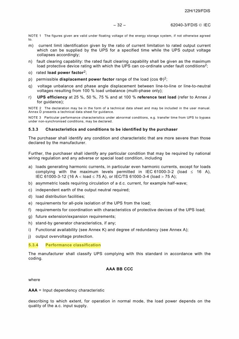
5.3.4 Performance classification
The manufacturer shall classify UPS complying with this standard in accordance with the coding.
AAA BB CCC
where
AAA = Input dependency characteristic
describing to which extent, for operation in normal mode, the load power depends on the quality of the a.c. input supply.
22H/129/FDIS
62040-3/FDIS Ó IEC – 33 –
NOTE 1 This classif ication is performance-based and does not exclude any specif ic technology or topology as the means for achieving compliance with such classif ication.
“VFD”:
UPS classified VFD shall protect the load from power outage.
The output of the VFD UPS is dependent on changes in a.c., input voltage and frequency and is not intended to provide additional corrective functions, such as those arising from the use of tapped transformers.
Compliance with VFD classification is verified when performing test of 6.2.2.7 and by observing that as a minimum the UPS switches from normal mode of operation to battery mode while input voltage is interrupted
“VI”:
UPS classified VI shall protect the load as requested for VFD and in addition from:
– under-voltage applied continuously to the input; – over-voltage applied continuously to the input.
An output voltage tolerance band narrower than input voltage window shall be defined by the manufacturer. The output of the VI UPS is dependent on a.c. input frequency and the output voltage shall remain within prescribed voltage limits (provided by additional corrective voltage functions, such as those arising from the use of active and/or passive circuits).
Compliance with VI classification is verified when performing tests of 6.4.1.1 and by observing that as a minimum the UPS output voltage remains within the prescribed limits and that the UPS remains in normal mode of operation while the input voltage is kept continuously (at least 1 min) at the maximum and the minimum value of the input voltage limits.
“VFI”:
UPS classified VFI is independent of supply (mains) voltage and frequency variations as specified in 5.2 and shall protect the load against adverse effects from such variations without depleting the stored energy source.
Compliance with VFI classification is verified when performing tests of 6.4.1.1 and 6.4.1.2 and by observing that as a minimum the output voltage and frequency remain within a specified output tolerance band while input voltage and frequency are moved in a wider input voltage and frequency tolerance band.
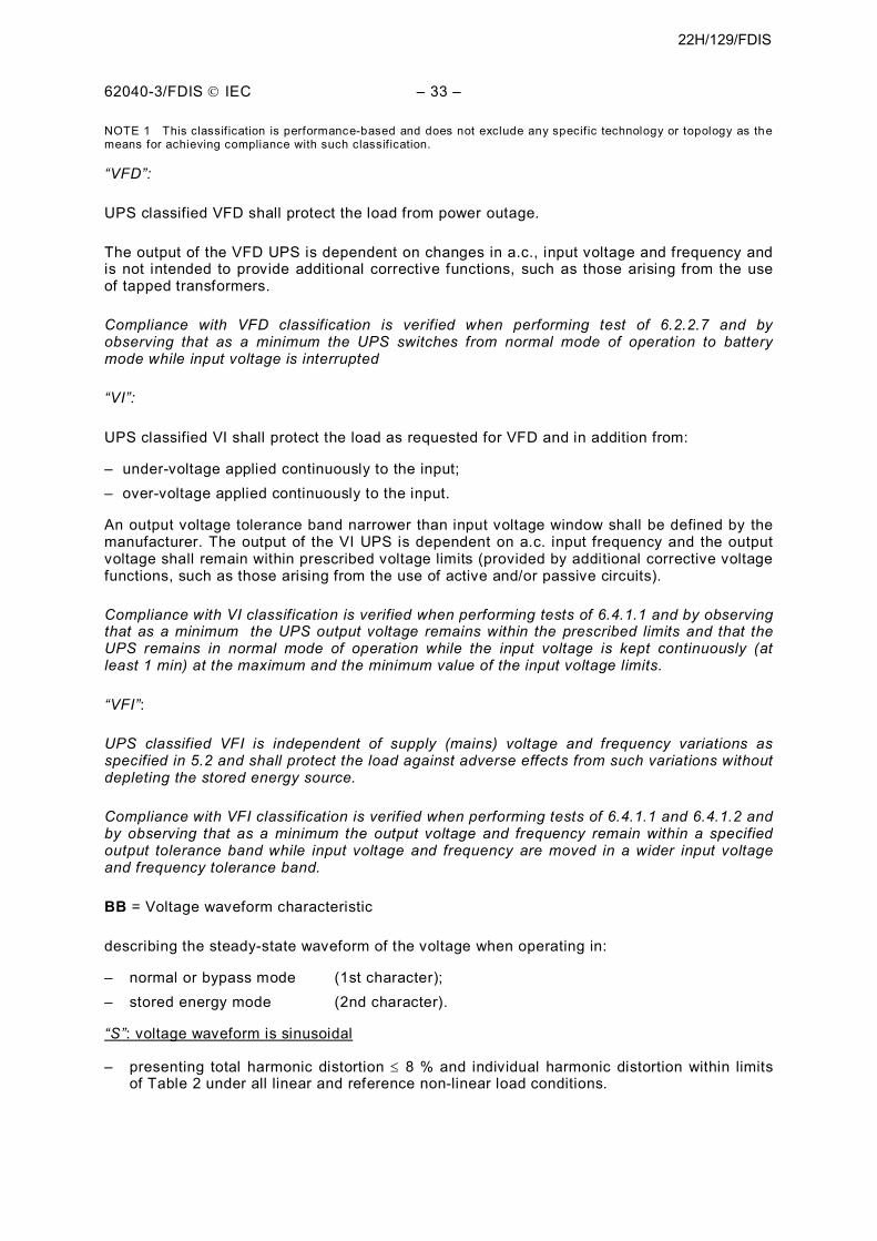
BB = Voltage waveform characteristic
describing the steady-state waveform of the voltage when operating in:
– normal or bypass mode (1st character); – stored energy mode (2nd character).
“S”: voltage waveform is sinusoidal
– presenting total harmonic distortion £ 8 % and individual harmonic distortion within limits of Table 2 under all linear and reference non-linear load conditions.
22H/129/FDIS
– 34 – 62040-3/FDIS Ó IEC
“X”: voltage waveform is sinusoidal/non-sinusoidal
– meeting “S” specification under all linear load condition; – not meeting “S” specification under rated non-linear load condition.
“Y”: voltage waveform is non-sinusoidal
– not meeting “S” specification under reference linear load condition.
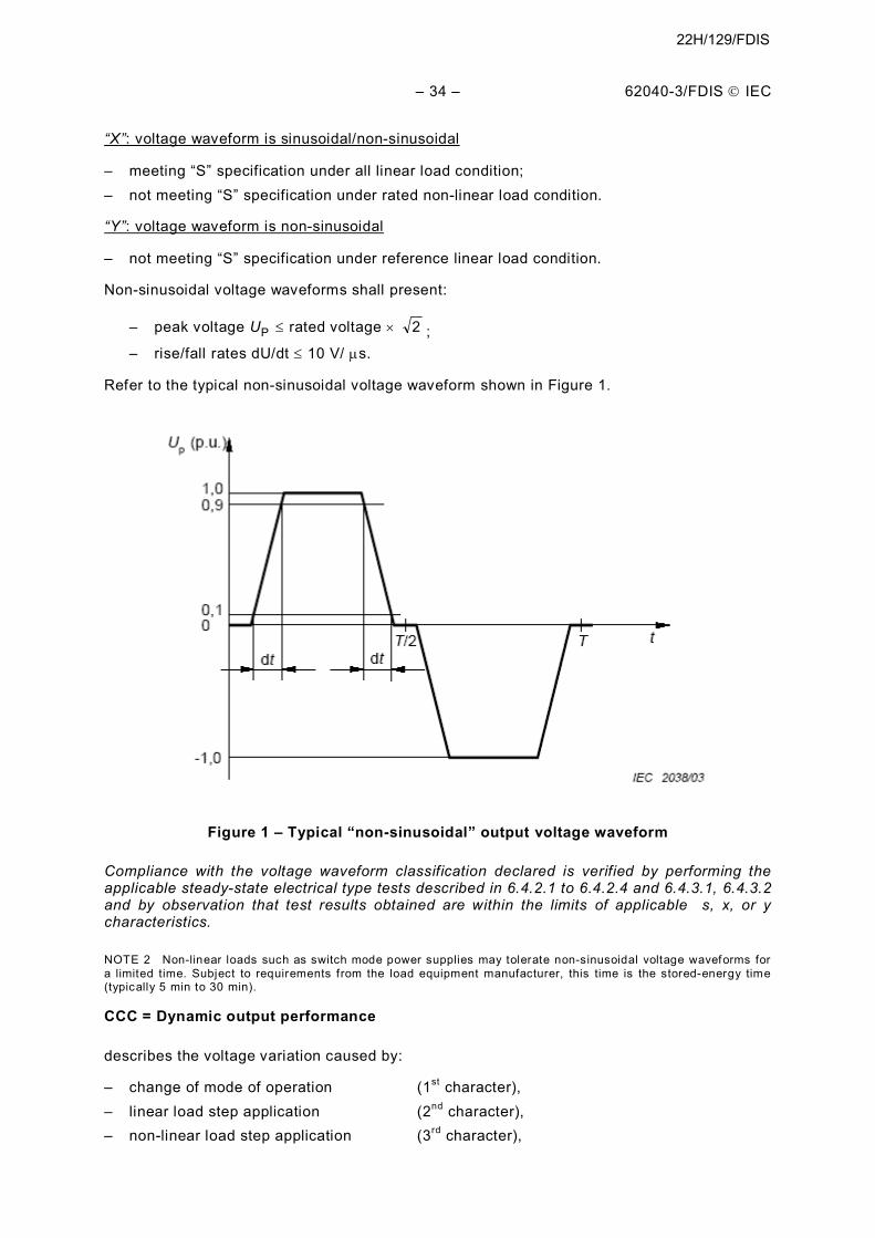
Non-sinusoidal voltage waveforms shall present:
– peak voltage UP £ rated voltage ´ 2 ; – rise/fall rates dU/dt £ 10 V/ ms.
Refer to the typical non-sinusoidal voltage waveform shown in Figure 1.
Figure 1 – Typical “non-sinusoidal” output voltage waveform
Compliance with the voltage waveform classification declared is verified by performing the applicable steady-state electrical type tests described in 6.4.2.1 to 6.4.2.4 and 6.4.3.1, 6.4.3.2 and by observation that test results obtained are within the limits of applicable s, x, or y characteristics.
NOTE 2 Non-linear loads such as switch mode power supplies may tolerate non-sinusoidal voltage waveforms for a limited time. Subject to requirements from the load equipment manufacturer, this time is the stored-energy time (typically 5 min to 30 min).
CCC = Dynamic output performance
describes the voltage variation caused by:
– change of mode of operation (1st character), – linear load step application (2nd character), – non-linear load step application (3rd character),
22H/129/FDIS
62040-3/FDIS Ó IEC – 35 –
where each character takes form of either 1, 2 or 3 with the following meaning:
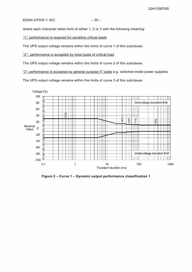
“1”: performance is required for sensitive critical loads
The UPS output voltage remains within the limits of curve 1 of this subclause.
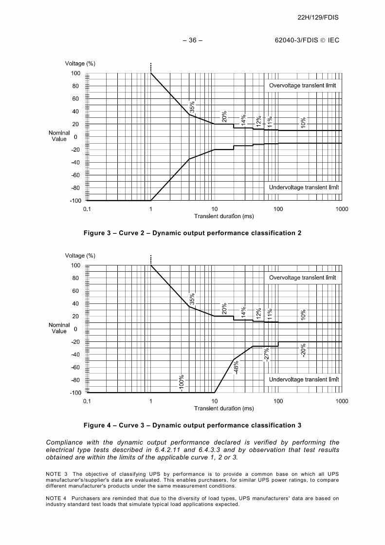
“2”: performance is accepted by most types of critical load
The UPS output voltage remains within the limits of curve 2 of this subclause.
“3”: performance is accepted by general purpose IT loads e.g. switched-mode power supplies.
The UPS output voltage remains within the limits of curve 3 of this subclause.
Figure 2 – Curve 1 – Dynamic output performance classification 1
22H/129/FDIS
– 36 – 62040-3/FDIS Ó IEC
Figure 3 – Curve 2 – Dynamic output performance classification 2
Figure 4 – Curve 3 – Dynamic output performance classification 3
Compliance with the dynamic output performance declared is verified by performing the electrical type tests described in 6.4.2.11 and 6.4.3.3 and by observation that test results obtained are within the limits of the applicable curve 1, 2 or 3.
NOTE 3 The objective of classifying UPS by performance is to provide a common base on which all UPS manufacturer's/supplier's data are evaluated. This enables purchasers, for similar UPS power ratings, to compare different manufacturer's products under the same measurement conditions.
NOTE 4 Purchasers are reminded that due to the diversity of load types, UPS manufacturers' data are based on industry standard test loads that simulate typical load applications expected.
22H/129/FDIS
62040-3/FDIS Ó IEC – 37 –
NOTE 5 The actual performance in a given application may be subject to variation under transient conditions since actual load ratings, individual sequencing, and start currents may differ from standardized test situations.
NOTE 6 Single-cord connected UPS designed to be installed by the operator for use in an off ice environment, either desk or f loor-mounted, and/or intended to be marketed by a third party without reference to the manufacturer, should, within the UPS rating, be capable of accepting any load suitable for connection to the public low voltage a.c. supply, unless any l imitations are stated by the manufacturer within the user instructions.
NOTE 7 Non-linear step loading is performed as described in 6.4.3.3.3 and 6.4.3.3.4.
NOTE 8 Refer to Annex H for guidance on measurement techniques.
NOTE 9 Refer to Annex B for examples of applicable UPS topologies.
5.4 Stored energy specification
5.4.1 General
This subclause specifies details that apply to a secondary battery, presently the most common technology selected to provide energy storage for use when the a.c. input supply is unavailable.
It is recognised that other technologies, e.g. flywheel systems, may replace the need for a battery system. Such technologies may be fully compatible with UPS characteristics primarily intended for batteries. With this in mind, subject to an agreement between the manufacturer/supplier and the purchaser and where applicable, the specification may be used for other stored energy technologies.
5.4.2 Battery
5.4.2.1 Requirements for all batteries
A battery intended to serve as an energy storage system for a UPS complying with this standard shall comply with the IEC 62040-1 requirements for location, ventilation, marking and protection of a battery.
5.4.2.2 Characteristics to be declared by the manufacturer
The manufacturer shall declare the following battery characteristics e.g. in the user manual or in the UPS Technical data sheet (see Clause D.6):
a) life (either design life or float service life - but not both); b) quantity of blocks or cells and of paralleled strings; c) nominal voltage of total battery; d) battery technology (vented or valve-regulated, lead-acid, NiCd, etc.); e) nominal capacity of total battery; f) stored energy time (see 6.4.4.1); g) restored energy time; h) ambient reference temperature; i) earth condition of d.c. link/isolation of d.c. link from input and/or output (remote battery only); j) r.m.s. ripple current during normal mode of UPS operation (if exceeding 5 % of the numerical Ah capacity [C10] );
When a remote battery is part of the supply, and if the power cabling and/or battery protection is not part of the supply, the following additional characteristics shall be declared:
k) nominal discharge current during stored energy mode; l) d.c. fault current rating;
22H/129/FDIS
– 46 – 62040-3/FDIS Ó IEC
The mains input supply shall be switched on to the UPS input coincident with various angular points on the input voltage waveform in order to determine the worst-case inrush current condition.
NOTE The test should be repeated suff iciently to obtain worst-case peak current which will normally be found for transformer coupled units, when switched at the zero voltage point and for direct rectif ier/capacitor loads at or near the peak of the input supply voltage waveform.
6.4.1.4 Harmonic distortion of input current
The harmonic distortion of the input current is tested at reference test load.
Compliance is verified when the total harmonic distortion figures of the UPS input current are within the limits declared by the manufacturer.
NOTE 1 The limits declared by the manufacturer should at least comply with those prescribed by IEC 61000-3-2 (UPS £ 16 A), IEC 61000-3-12 (16 A < UPS £ 75 A), or IEC/TS 61000-3-4 (UPS > 75 A) taking into consideration the minimum short-circuit power capacity of the a.c. input supply as declared by the manufacturer.
NOTE 2 Where the reference test load is implemented by means of returning the output power to the UPS input, the harmonic distortion of the input current of concern is that actually drawn by the UPS input (as opposed to that drawn from the a.c. input source).
6.4.1.5 Power factor
The input power factor is tested at reference test load in normal mode of operation and at rated a.c. input supply conditions.
Compliance is verified when the input power factor of the UPS input current is equal or greater that that declared by the manufacturer
NOTE Where the reference test load is implemented by means of returning the output power to the UPS input, the input power factor of concern is that referred to the current actually drawn by the UPS input (as opposed to that drawn from the a.c. input source).
6.4.1.6 Efficiency
The UPS efficiency shall be measured at 25 %, 50 %, 75 % and 100 % reference test load as prescribed in Annex J.
Compliance is verified when the computed efficiency values are equal to or greater than those declared by the manufacturer.
NOTE Refer to Annex I for applicable minimum eff iciency values to be considered .
6.4.1.7 Backfeed protection
Automatic backfeed protection is a safety requirement not within the scope of this standard.
NOTE Backfeed protection compliance is verif ied during the applicable UPS safety certif ication. See Annex I of IEC 62040-1.
6.4.1.8 Residual earth current
Residual earth current (“earth leakage“) is a safety requirement not within the scope of this standard.
NOTE Earth leakage compliance is verif ied during the applicable UPS safety certif ication. See Subclause 8.1 General provisions for earth leakage of IEC 62040-1.
22H/129/FDIS
– 94 – 62040-3/FDIS Ó IEC
Annex J (normative)
UPS efficiency –
Methods of measurement
J.1 General
This annex prescribes conditions and methods to be followed when determining UPS efficiency during type tests specified in 6.4.1.6.
J.2 Measurement conditions
J.2.1 Environmental conditions
The ambient temperature shall be between 20 °C to 30 °C and remaining environmental conditions shall be within the limits specified in 4.2.
J.2.2 Operational and electrical conditions
It is recognized that optimum efficiency for some UPSs can be achieved with load conditions that do not present power factor (PF)=1. However, for the purpose of this annex, the efficiency measurements shall be performed with a reference test load of PF=1 capable of being adjusted so that the UPS delivers 25 %, 50 %, 75 % and 100 % of the active power (W) for which it is rated. The following requirements apply for each measurement:
a) the UPS shall operate in normal mode; b) transfer of energy to and from the energy storage system shall be prevented during the
test. The energy storage system may be disconnected during the test to prevent such transfer of energy;
c) the UPS and the load shall have been operated for a sufficient length of time to reach steady state conditions. The length of time determined during temperature rise type tests plus 25 % is considered sufficient. Alternatively, trend variation of less than 2 ˚C temperature variation over not less than three consecutive readings with no less than 10 min interval may be considered steady-state for the purpose of this annex;
d) each load condition shall be within the range of 95 % to 105 % of the intended load and the power factor shall be 0,99 or greater;
e) all UPS sub-systems intended to be operational in normal mode shall be activated;
f) the a.c. input to the UPS shall be at 97 % to 103 % of the rated voltage and 99 % to 101 % of the rated frequency and otherwise within the tolerances specified in IEC 61000-2-2;
NOTE The test with resistive load is considered to be the most reliable in terms of repeatability and constitutes a solid base for the evaluation of eff iciency improvements at all load levels.
J.2.3 Instrumentation
The combination of instruments and transducers used for the measurement of UPS efficiency shall:
– provide true r.m.s. measurements of the active input and output power, with an uncertainty at full rated load of less than or equal to 0,5 % at the 95 % confidence level notwithstanding that voltage and current waveforms can include harmonic components;
– measure input and output values simultaneously.
22H/129/FDIS
62040-3/FDIS Ó IEC – 95 –
NOTE 1 The confidence level of an instrument’s uncertainty should be understood as the probability of measurements presented by such instrument being accurate within the uncertainty limits. A normal distribution of data with coverage factor 1,960 represents a 95 % confidence level which is a generally accepted level. For further information, refer to ISO/IEC Guide 98-3.
NOTE 2 Simultaneous input and output measurements are generally provided through separate input and output instruments. Nevertheless, one single multi-channel instrument providing fast serial sampling (“multiplexed sampling”) is also deemed to provide simultaneous measurements.
NOTE 3 For tolerances, refer to 7.8 of IEC 60146-1-1.
J.3 Measurement method
J.3.1 Standard method
Under the conditions specified in J.2.1 and J.2.2, using the instrumentation described in J.2.3, the measurement of the UPS efficiency shall be carried out as follows:
a) 100 % reference test load shall be applied to the output of the UPS and a suitable stabilization time be allowed to reach the steady-state conditions as specified above;
b) the active input and output power (W) shall be measured simultaneously in three successive readings taken no more than 15 min apart. The UPS efficiency shall be calculated for each reading;
NOTE 1 Where the reference test load is implemented by means of returning the output power to the UPS input, the total input power equals the UPS output power plus that supplied by the a.c. input source.
NOTE 2 W here a UPS is connected to more than one input source, the active input power to be considered is the sum of all inputs.
NOTE 3 Where a UPS supplies more than one output, the active output power to be considered is the sum of all outputs.
c) the arithmetic mean of the 3 UPS efficiencies calculated in b) shall then be obtained. The result is considered to be the value of the efficiency measure;
d) steps a), b) and c) shall be repeated but for 75 %, 50 %, and 25 % reference load conditions.
J.3.2 Alternative method
It is acknowledged that instruments and transducers meeting the requiremens of J.2.3 may not be commercially available. Therefore, the use of instruments and transducers providing measurement uncertainty greater than allowed by J.2.3 is permitted provided that the standard method is varied as follows.
In J.3.1, replace step c) by:
c) the input and output measuring instruments and transducers if any, shall be exchanged and step b) shall be repeated. The arithmetic mean of all 6 resulting UPS efficiencies is considered to be the value of the efficiency measure.
J.4 Test report
A recommended format for the test report is provided in Clause D.6. Should the UPS technical sheet in Clause D.6 be used, the sheet shall be completed for each performance classification declared by the manufacturer.
22H/129/FDIS
– 96 – 62040-3/FDIS Ó IEC
The following information shall be recorded in the test report:
a) equipment details
– brand, model, type, and serial number; – product description, as appropriate; – rated voltage and frequency; – rated output active and apparent power; – details of manufacturer marked on the product (if any); – in the case of products with multiple functions or with options to include additional
modules or attachments, the configuration of the appliance as tested shall be noted in the report.
NOTE The details above can be found and should be consistent with those of Clause D.6 Technical data sheet ‒ Manufacturer's declaration.
b) test parameters
– ambient temperature (°C); – input and output test voltage (V) and frequency (Hz); – total harmonic input voltage distortion; – information and documentation on the instrumentation, set-up and circuits used for
electrical testing.
c) measured data
– efficiency in % rounded to the first decimal place at the given rated load fraction; – measurement method used: either J.3.1 or J.3.2 of IEC 62040-3; – any notes regarding the operation of the equipment.
d) test and laboratory details
– test report number/reference; – date of test; – name and signature of authorized test person(s).
22H/129/FDIS