artifacts at cardiac ct: physics and solutions
TRANSCRIPT

Ima
gIn
g P
hy
sIc
s 2064
Artifacts at Cardiac CT: Physics and Solutions1
Computed tomography is vulnerable to a wide variety of artifacts, including patient- and technique-specific artifacts, some of which are unique to imaging of the heart. Motion is the most common source of artifacts and can be caused by patient, cardiac, or respira-tory motion. Cardiac motion artifacts can be reduced by decreasing the heart rate and variability and the duration of data acquisition; adjusting the placement of the data window within a cardiac cycle; performing single-heartbeat scanning; and using multisegment reconstruction, motion-correction algorithms, and electrocardio-graphic editing. Respiratory motion artifacts can be minimized with proper breath holding and shortened scan duration. Partial volume averaging is caused by the averaging of attenuation values from all tissue contained within a voxel and can be reduced by improving the spatial resolution, using a higher x-ray energy, or displaying images with a wider window width. Beam-hardening artifacts are caused by the polyenergetic nature of the x-ray beam and can be reduced by using x-ray filtration, applying higher-energy x-rays, altering patient position, modifying contrast material protocols, and applying certain reconstruction algorithms. Metal artifacts are complex and have multiple causes, including x-ray scatter, under-penetration, motion, and attenuation values that exceed the typical dynamic range of Hounsfield units. Quantum mottle or noise is caused by insufficient penetration of tissue and can be improved by increasing the tube current or peak tube potential, reconstructing thicker sections, increasing the rotation time, using appropriate pa-tient positioning, and applying iterative reconstruction algorithms.
©RSNA, 2016 • radiographics.rsna.org
Kevin Kalisz, MD
Ji Buethe, MD2 Sachin S. Saboo, MD, FRCR Suhny Abbara, MD Sandra Halliburton, PhD Prabhakar Rajiah, MD, FRCR
Abbreviations: ECG = electrocardiography, PVC = premature ventricular contraction
RadioGraphics 2016; 36:2064–2083
Published online 10.1148/rg.2016160079
Content Codes: 1From the Department of Radiology, University Hospitals Cleveland Medical Center, Cleveland, Ohio (K.K., J.B.); Department of Radiology, Car-diothoracic Imaging, UT Southwestern Medical Center, E6.120 B, Mail Code 9316, 5323 Harry Hines Blvd, Dallas, TX 75390-8896 (S.S.S., S.A., P.R.); and Philips Healthcare, Cleveland, Ohio (S.H.). Presented as an education exhibit at the 2015 RSNA Annual Meeting. Received March 29, 2016; revision requested June 16 and received July 25; accepted August 9. For this journal-based SA-CME activity, the authors S.A., S.H., and P.R. have provided disclosures (see end of article); all other authors, the editor, and the reviewers have disclosed no relevant relationships. Address cor-respondence to P.R. (e-mail: [email protected]).
2Current address: Department of Interventional and Diagnostic Radiology, Johns Hopkins Hospi-tal, Baltimore, Md.
©RSNA, 2016
After completing this journal-based SA-CME activity, participants will be able to:
■ Discuss commonly encountered imag-ing artifacts at cardiac CT.
■ Review the causes of these artifacts and explain how they can obscure or simulate pathologic conditions.
■ Describe techniques that can be used to correct or reduce imaging artifacts at cardiac CT.
See www.rsna.org/education/search/RG.
SA-CME LEArning ObjECTivES
introductionIn recent years, cardiac computed tomography (CT) has gained widespread acceptance for noninvasive assessment of a wide variety of cardiac diseases. The most well-established role of cardiac CT is in evaluation of coronary artery disease, because of the strong negative predictive value and the ability to effectively exclude the presence of coronary artery disease in symptomatic patients, especially in the intermediate-risk group (1). In addition, cardiac CT is emerging as a useful means of evaluation of other structural and functional aspects of the heart (2,3). Continued technologic advancements have helped make cardiac CT a powerful assessment tool. Recent innovations such as faster gantry rotation and an increased num-ber of detector rows have allowed for improved temporal resolution
This copy is for personal use only. To order printed copies, contact [email protected]

RG • Volume 36 Number 7 Kalisz et al 2065
table feed as the gantry is rotating with a pitch less than 1. Images are typically reconstructed in one phase, but any phase can be reconstructed, which allows ECG editing and functional evaluation. The radiation dose is relatively high because of acquisition throughout the cardiac cycle but can be minimized by using tube current modulation, where maximal tube current is applied during only one phase of the R-R interval.
With prospective ECG triggering, image data are acquired during only one phase of the cardiac cycle, triggered from the R peak on the ECG tracing. The x-ray tube operates in the axial or “step-and-shoot” mode, where data through a segment of the heart are acquired during a preset portion of the R-R interval. After the data are acquired, the table moves to the next position, and scanning is repeated during a subsequent heartbeat to acquire the next section of data. This technique is associated with a significantly lower radiation dose but requires a low heart rate, and it is not possible to perform ECG editing or functional evaluation. With the latest generation of dual-source scanners, prospective triggered acquisition can be performed in a helical mode and at a high pitch of up to 3.4. The gaps in data expected with a high-pitch scanning mode are filled by data from the second x-ray tube. As a result, the entire heart can be scanned in one heartbeat, thus minimizing artifacts. However, this technique requires a steady low heart rate (typically less than 60 beats per minute). Wide-array detectors (ie, 256- or 320-section detectors) and volume scanning enable z-axis coverage of up to 32 cm, which also enables acquisition of the images within one heartbeat. Temporal resolution is an indicator of the ability to resolve fast-mov-ing objects and, in the context of cardiac CT, is defined as the time interval over which the data needed to reconstruct cardiac CT images are acquired. Temporal resolution is vital for imaging the coronary arteries and is primarily determined by the gantry rotation speed. A lower number (in milliseconds) indicates better temporal resolution than a higher number. Temporal resolution is im-proved by a factor of two by utilizing partial scan reconstruction, where only 180° of the projection data (plus the fan angle) are used at any particu-lar z-axis position to generate an image. Hence the temporal resolution is approximately one-half of the gantry rotation speed for a single-source scanner and one-fourth of the gantry rotation speed for a dual-source scanner (6).
Motion ArtifactMotion artifact is the most common artifact seen at cardiac CT and includes cardiac, respiratory, and gross patient motion.
and z coverage, yielding improved image qual-ity. Multispectral imaging with different imple-mentations has shown some potential in further characterization and improved visualization of cardiovascular structures, particularly in perfusion imaging (4). Simultaneously, implementation of dose-reduction strategies, including electrocardi-ography (ECG)–triggered axial acquisition, tube current modulation, low tube potential selection, and iterative reconstruction techniques, have significantly reduced the average radiation doses associated with cardiac CT, with some patients requiring only submillisievert levels (5).
Despite these improvements in cardiac CT technology, examinations are still vulnerable to a number of artifacts from patient- and technique-specific causes. Artifacts at cardiac CT may ob-scure or simulate pathologic conditions. Failure to recognize these potentially reversible artifacts may lead to either underdiagnosis or overtreat-ment, both of which are associated with increased patient morbidity and mortality.
This article illustrates common artifacts encountered at cardiac CT, details the physics behind their origin, and describes methods to minimize or eliminate these artifacts. A sum-mary of CT artifacts with causes and solutions is provided in Table 1.
Cardiac CT Image Acquisition and Reconstruction Techniques
Cardiac CT is performed with ECG gating, which may be either retrospective ECG gating or pro-spective ECG triggering. With retrospective ECG gating, data are acquired throughout the cardiac cycle in a spiral (helical) mode with continuous
TEAChing POinTS ■ Motion artifact is the most common artifact seen at cardiac CT
and includes cardiac, respiratory, and gross patient motion.
■ Decreasing the mean heart rate and variability is the most important step in minimizing motion artifact, resulting in bet-ter images that provide improved sensitivity for detection of coronary artery stenosis.
■ Within the heart, respiratory motion produces artifacts similar to those arising from cardiac motion, including discontinuity on through-plane images and blurring, ghosting, winging, and streaking on cross-sectional–plane images. Unlike cardiac motion, respiratory motion may also produce similar artifacts in extracardiac structures such as the sternum, rib cage, and descending thoracic aorta.
■ The effect of beam hardening is magnified when an x-ray encounters highly attenuating objects such as metal (clips, markers, and wires), bone, or iodinated contrast agent, as well as high-contrast interfaces.
■ Quantum mottle (CT noise) occurs secondary to low pho-ton counts reaching the detectors and leading to a larger Poisson error.
2066 November-December 2016 radiographics.rsna.org
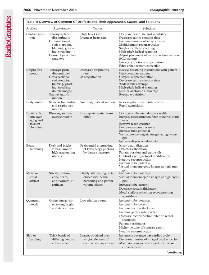
Table 1: Overview of Common CT Artifacts and Their Appearance, Causes, and Solutions
Artifact Appearance Causes Solutions
Cardiac mo-tion
Through-plane: discontinuity
Cross-sectional: stair-stepping, blurring, ghost-ing, streaking
Dense objects: dark shadows
High heart rateIrregular heart rate
Decrease heart rate and variabilityDecrease gantry rotation timeIncrease number of x-ray sourcesMultisegment reconstructionSingle-heartbeat scanningHigh-pitch helical scanningAdjust placement of reconstruction windowECG editingIntracycle motion compensationEdge enhancement/correction
Respiratory motion
Through-plane: discontinuity
Cross-sectional: stair-stepping, blurring, ghost-ing, streaking, double images
Sternal and rib motion
Increased respiratory rate
Misregistration
Review breathing instructions with patientHyperventilate patientOxygen supplementationDecrease gantry rotation timeWide z-axis coverageHigh-pitch helical scanningReduce anatomic z-coverageRepeat acquisition
Body motion Same as for cardiac and respiratory motion
Voluntary patient motion Review patient scan instructionsRapid acquisition
Partial vol-ume aver-aging and calcium blooming
Blurring and size overestimation
Inadequate spatial reso-lution
Decrease collimated detector widthIncrease reconstruction filter or kernel sharp-
nessIterative reconstructionDecrease section thicknessIncrease tube potentialVirtual monoenergetic images at high ener-
giesIncrease display window width
Beam hardening
Dark and bright streaks around high-attenuating objects
Preferential attenuating of low-energy photons by dense structures
X-ray beam filtrationDetector calibrationPatient position and gantry tiltContrast agent protocol modificationIterative reconstructionIncrease tube potentialVirtual monoenergetic images at high ener-
giesMetal or
streak artifact
Streak, motion, cone beam, and “windmill” artifacts
Highly attenuating metal object with beam-hardening and partial volume effects
Increase tube potentialVirtual monoenergetic images at high ener-
giesIncrease tube currentDecrease section thicknessMetal artifact reduction reconstruction
algorithmsQuantum
mottleGrainy image, al-
ternating bright and dark streaks
Low photon count Increase tube potentialIncrease tube currentIncrease section thicknessIncrease gantry rotation timeDecrease reconstruction filter or kernel
sharpnessPatient positioningHigher volume of contrast agentIterative reconstruction
Slab or banding
Thick bands of differing contrast enhancement
Images obtained over varying degrees of contrast enhancement
Increase z-coverage per cardiac cycleDecrease number of imaged cardiac cyclesMaintain homogeneous level of contrast
enhancement
(continues)
RG • Volume 36 Number 7 Kalisz et al 2067
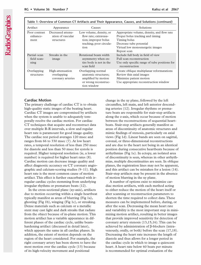
Table 1: Overview of Common CT Artifacts and Their Appearance, Causes, and Solutions (continued)
Artifact Appearance Causes Solutions
Poor contrast enhance-ment
Decreased attenu-ation of vascular structures
Low volume, density, or flow rate; extravasa-tion; improper bolus tracking; poor circula-tion
Appropriate volume, density, and flow rateProper bolus tracking and timingTiming bolusDecrease tube potentialVirtual low monoenergetic imagesRepeat scan
Partial–scan field scan-ning
Streaks in the image
Rotational beam width asymmetry when en-tire body is not in the scan field
Include full body in field of viewFull scan reconstructionUse only specific range of tube positions for
reconstruction
Overlapping structures
High-attenuation overlapping coronary arteries
Overlapping normal anatomic structures; amplified by motion or wrong reconstruc-tion window
Create oblique multiplanar reformatationsReview thin axial imagesMinimize patient motionUse appropriate reconstruction window
Cardiac MotionThe primary challenge of cardiac CT is to obtain high-quality static images of the beating heart. Cardiac CT images are compromised by artifacts when the system is unable to adequately tem-porally resolve the cardiac motion. For cardiac CT techniques that acquire and reconstruct data over multiple R-R intervals, a slow and regular heart rate is paramount for good image quality. The cardiac rest period averages 120 msec and ranges from 66 to 330 msec (7). At low heart rates, a temporal resolution of less than 250 msec for diastole and less than 50 msec for systole is required. Higher temporal resolution (ie, a lower number) is required for higher heart rates (8). Cardiac motion can decrease image quality and affect diagnostic accuracy on CT coronary angio-graphic and calcium-scoring studies (9–11). High heart rate is the most common cause of motion artifact. This effect is further exacerbated with ir-regular cardiac cycles stemming from underlying irregular rhythms or premature beats (12).
In the cross-sectional plane (xy-axis), artifacts due to motion occurring within a single heartbeat typically manifest as areas of blurring (Fig 1a), ghosting (Fig 1b), winging (Fig 1c), or streaking. Dense materials such as calcium or a metallic stent may cast light and dark streaks that radiate from the object because of in-plane motion. This motion artifact has a variable appearance in dif-ferent phases of the cardiac cycle, unlike beam-hardening artifact (discussed in detail later), which appears the same in all cardiac phases. In addition, the extent of motion depends on the region of the heart considered. For example, the right coronary artery has been shown to have the most motion over the cardiac cycle (13) because of its high-velocity movement and positional
change in the xy plane, followed by the left circumflex, left main, and left anterior descend-ing arteries (12). Irregular rhythms or prema-ture beats are responsible for stair-step artifacts along the z-axis, which occur because of motion between the reconstructions of sequential heart-beats. Stair-step artifacts generally manifest as areas of discontinuity of anatomic structures and mimic findings of stenosis, particularly on axial views (Fig 1d). Linear bands are seen on sagittal, coronal, or three-dimensional reconstructions and are due to the heart not being in an identical position during consecutive heartbeats because of arrhythmias (Fig 1e). In ectopy, an isolated area of discontinuity is seen, whereas in other arrhyth-mias, multiple discontinuities are seen. In oblique planes, the registration lines may not be apparent, and this artifact can be mistaken for a lesion (14). Stair-step artifacts may be present in the absence of motion blurring in the xy plane.
A number of options exist to minimize car-diac motion artifacts, with each method acting to either reduce the motion of the heart itself or alter scanning or reconstruction parameters to shorten the time required to collect data. These measures can be implemented before, during, or after the scan. Decreasing the mean heart rate and variability is the most important step in mini-mizing motion artifact, resulting in better images that provide improved sensitivity for detection of coronary artery stenosis (13,15,16). This can be achieved by administration of β-blockers (intra-venously, orally, or both) before the scan (17,18). Decreasing the heart rate increases the length of diastole and thus allows for a longer period in the cardiac cycle in which to image a quiescent heart. A heart rate below 60 beats per minute is recommended for optimal evaluation of the

2068 November-December 2016 radiographics.rsna.org
acerbate this artifact. However, on some modern scanners, the pitch is automatically selected by the scanner on the basis of the heart rate. Us-ing an effective breath-holding technique and decreasing the duration of breath holding can minimize this artifact (12).
A scanner-based solution that can reduce misregistration artifacts along the z-axis is to increase the z-axis coverage per rotation for pro-spective ECG-triggered axial scanning. The more cardiac anatomy scanned per rotation, the fewer
Figure 1. Cardiac motion artifacts. (a) Axial CT image shows blurring of the right coronary artery (arrow). (b) Axial CT image shows ghosting of the ascending aorta (arrow) and right coronary artery. (c) Axial CT im-age shows the winging appearance of the right coronary artery (arrow). (d, e) Axial CT image (d) and coronal reconstruction (e) show the effects of misregistration or stair-step artifact, which is seen as motion of the aortic root (arrows in d) and a linear band of misregistration (arrows in e).
coronary arteries, although this number depends on the temporal resolution of the scanner (17). β-blockers may be ineffective in some patients, or patients may have contraindications such as hypotension, severe bronchospasm, or allergy. The heart rate may rapidly increase during the scan because of patient anxiety or contrast agent injection. Variations in heart rate during breath holding, with an initial decrease and a later in-crease, may result in motion artifacts in the distal coronary segments if the scanning direction is craniocaudal. Inappropriate pitch selection may also result because of this variation and may ex-

RG • Volume 36 Number 7 Kalisz et al 2069
resolution (27). The physics of temporal resolution is complex and beyond the scope of this article. However, with a single-source scanner, there are two approaches used to improve temporal resolu-tion: a direct short-scan fan-beam filtered back-projection reconstruction with a Parker weighting scheme, or a rebinning step to parallel-beam ge-ometry, followed by a 180° parallel-beam filtered back-projection reconstruction (27). Simplistically, temporal resolution at cardiac CT is primarily determined by the gantry rotation speed. Temporal resolution is improved by a factor of two by utiliz-ing partial scan reconstruction versus full scan reconstruction. There is an additional twofold im-provement when a second x-ray source is added. If multiple scanners are available, the scanner that provides the fastest gantry rotation time and the highest temporal resolution should be chosen, especially for high and irregular heart rates (Table 2). With dual-source scanners, temporal resolution can be as high as 66 msec (28,29).
Effective temporal resolution can also be improved by using multisegment reconstruction, where the image is reconstructed from projec-tion data from the same phase of the cardiac cycle at successive heartbeats, as the scan utilizes only a short data window in each cycle (Fig 2). The temporal resolution is the gantry rotation
opportunities there are for misregistration when combining data sections. Misregistration artifacts are eliminated with the use of wide-area detec-tors (ie, 16 cm) that can image the entire heart in one cardiac cycle within a single gantry rota-tion (19–23). Prospective ECG-triggered spiral high-pitch acquisitions with second- and third-generation dual-source scanners can also be used to obtain images of the heart in one cardiac cycle with high accuracy and low radiation dose, pro-vided the heart rate is slow and regular (24–26). Although a high pitch produces data gaps with a single-source scanner, these gaps are not seen with dual-source scanners because the data from the second tube are used to fill data gaps and avoid artifacts (26).
In-plane motion artifacts are minimized by im-proving the temporal resolution. Higher temporal resolution implies that the raw data from which an image was generated were acquired in a shorter time interval than an image with lower temporal
Table 2: Features of the Latest Generation of Cardiac CT Scanners
Scanner Name and Manufacturer
Collimated Detector
Row Width (mm)
No. of Detector
Rows Coverage (mm/rotation)
Rotation Time
(msec)
Temporal Resolution
(msec)
Revolution (GE Healthcare; Waukesha, Wis)
0.625 256 160 280 140
Scenaria (Hitachi Medical Sys-tems America; Twinsburg, Ohio)
0.6 64 38.4 350 175
Brilliance iCT (Philips Health-care; Cleveland, Ohio)
0.6 128 80 270 135
Definition Flash (Siemens Healthineers; Malvern, Pa)
0.625 128 38.4 (458 mm/sec with high-pitch spiral)
280 75
Somatom Force (Siemens Healthineers)
0.625 96 57.6 (737 mm/sec with high-pitch spiral)
250 66
Aquilion ONE (Toshiba America Medical Systems; Tustin, Calif)
0.5 320 160 280 140
NExCT 7 (Samsung NeuroLogica; Danvers, Mass)
0.6 128 76.8 250 125
Figure 2. Multisegment reconstruction. Schematic diagram shows image acquisition (colored boxes) in mid-late diastole during multiple successive cardiac cycles. Image data from multiple cycles are then combined to produce the image, thus improving the effec-tive temporal resolution. The circle represents the angular range.
2070 November-December 2016 radiographics.rsna.org
time divided by 2n, where n is the number of segments. Thus, temporal resolution is improved with a higher number of cardiac cycles used. This is possible only with retrospective ECG gating and a regular heart rate and rhythm (6). However, the maximum temporal resolution only takes effect at a certain heart rate, and the given values are only the best possible temporal val-ues. Data are typically used from two segments, yielding an effective temporal resolution of up to one-fourth the gantry rotation time. This may be useful in sinus tachycardia but is not useful in variable heart rates because this technique re-quires the heart to stay in the same position over multiple cardiac cycles. A lower pitch will also be required in this setting (8). Decreasing the pitch may subsequently have a variable effect on the radiation dose, with the dose remaining constant with scanners utilizing automatic exposure con-trol but potentially increasing with scanners with a manual exposure mode (30).
Intracycle motion correction algorithms com-pensate for coronary motion by using information from cardiac phases adjacent to the target phase within a single cardiac cycle to characterize ves-sel motion (path and velocity). These algorithms determine the actual vessel position at the target phase and adaptively compensate for residual mo-tion in that phase, thus effectively compressing the reconstruction temporal window within the area of interest. Because this technique operates on a single cycle, it is less vulnerable to beat-to-beat variability than is multisegment reconstruction (31). Motion correction algorithms have been shown to improve image quality, interpretability, and diagnostic accuracy in patients with normal, high, and irregular heart rates, especially in evalua-tion of the right coronary artery (32–34).
Some options are available after acquisition to improve motion artifact. The placement of the reconstruction window can make a big difference in the appearance of motion artifacts. At low heart rates (less than 60 beats per minute), artifacts are typically minimized in mid to late diastole (70% R-R interval), while at high heart rates (greater than 65 beats per minute), artifacts are typi-cally minimized in end systole or early diastole (30%–40% R-R interval) (16). Individual coro-nary arteries, however, are sometimes well seen at different phases of the R-R interval (right coronary artery, 40%; left circumflex coronary artery, 50%; left anterior descending artery, 60%–70%), neces-sitating the use of multiple reconstructions for evaluation (Fig 3a). Similarly, for other structures, there may be a specific phase where the artifact is lower or eliminated. In some instances, it might be desirable to reconstruct all possible phases at 3%–5% increments and select the phase with the
least motion artifact (Fig 3b, 3c). However, phase selection is limited for prospective ECG-triggered axial acquisition and ECG-based tube current modulated helical scanning.
ECG editing is another postacquisition tool to reduce motion artifact on retrospective ECG-gated helical images. After the ECG tracing during ac-quisition is reviewed, if the correct segment of R-R interval was not used for reconstruction, the ECG editing feature can be used to disable or eliminate an inappropriate segment or add a different region, depending on the type of arrhythmia present. Occa-sionally, data may be needed from a different phase from each R-R interval. If there is an ECG gating problem such as triggering from a T wave (Fig 4a–4c) or an atrial pacing spike, new synchroniza-tion markers are placed in the appropriate position. The different techniques of ECG editing used for different arrhythmias are described in Table 3. For example, in PVCs with a post-PVC pause, data from the beat before the PVC are eliminated, and instead one or two separate synchronization mark-ers are placed in the prolonged diastolic period of the PVC (Fig 4d–4f) (14). Ventricular tachycardia cannot be fixed by using ECG editing.
Edge enhancement/correction algorithms are available from some vendors for minimizing stair-step artifacts between slabs. These vessel-driven nonrigid registration algorithms aim to auto-matically compensate for misalignment between beats from volumetric data of coronary arteries and thus may improve stair-step artifacts (31). However, this process may result in blurring of the interfaces and may make interpretation of the coronary arteries more challenging. Further studies are needed to validate the clinical utility of these algorithms.
Respiratory MotionSimilar to cardiac motion, patient respiration can also produce motion artifacts. Respiratory motion artifacts arise when a patient is unable to maintain a breath hold during image acquisition. Scan duration and required breath-hold times vary according to the scanner technology and selected scan parameters. Even for the shortest scans, dyspneic patients may still be unable to suspend respiration during data acquisition. The risk for respiratory motion artifact is greatest to-ward the end of the acquisition, when patients are no longer able to hold their breath. Respiratory artifacts are more common in the inferior portion of the heart (if scanning is craniocaudal). As with cardiac motion artifacts, respiratory motion arti-facts result from misregistration of data acquired during successive cardiac cycles.
Within the heart, respiratory motion produces artifacts similar to those arising from cardiac

RG • Volume 36 Number 7 Kalisz et al 2071
Figure 3. Selection of reconstruction window. (a) Axial CT images obtained at different phases of the cardiac cycle (from 0% to 80% R-R interval) show that the right coronary artery has varying degrees of motion in each of the cardiac phases. In this patient, the motion is least in the 50% and 80% phases of the R-R interval. (b) Axial CT image reconstructed from the 75% R-R interval in a patient with atypical chest pain shows winging of the right coronary artery (arrow). (c) Reconstruction at the 40% R-R interval (same patient as in b) shows that the artifact has disappeared, with good-quality visualization of the right coronary artery (arrow).

2072 November-December 2016 radiographics.rsna.org
Figure 4. ECG editing in two patients. (a–c) Cardiac CT in a patient with chest pain. (a) Axial CT im-age shows extensive blurring of the right coronary artery and aortic root (arrows). (b) Review of the ECG tracing showed faulty triggering of the acquisition from unusual tall T waves (arrows). The blue bars rep-resent the cardiac phases used for data reconstruction, and the numbers represent the heart rate for that specific R-R interval. ECG editing was performed, and the synchronization markers from the tall T waves were removed. (c) Resulting axial CT image shows no motion artifact. (d–f) Cardiac CT in a different patient. (d) Axial CT image obtained at the 70% R-R interval shows blurring of the right coronary artery (arrow). (e) ECG tracing shows multiple premature ventricular contractions (PVCs) (arrows) leading to inappropriate triggering during the ectopic beats. The synchronization markers from the PVCs were removed by using the ECG editing feature. (f) Resulting axial CT image has no motion artifacts. Arrow = right coronary artery.

RG • Volume 36 Number 7 Kalisz et al 2073
Table 3: Postprocessing Techniques for Reducing Artifacts from Arrhythmias
Problem Solution
Sinus tachycardia Multisegment reconstructionGating issue: triggering from T wave/atrial
pacingNew synchronization markers (syncs) in appropriate position
PVC with post-PVC pause Eliminate sync from PVC, two separate syncs in diastolic pausePVC without pause Eliminate sync from PVCPremature atrial contraction Eliminate premature atrial contraction sync or retain premature atrial
contraction sync with reconstruction from best systolic phaseFirst-degree atrioventricular block Sync just before R wave or in systolic phaseAtrial tachycardia Sync in best systolic phaseVentricular tachycardia Cannot be fixedAtrial fibrillation End diastolic sync in slow heart rates
Systolic sync in high heart ratesTransient episode: elimination of sync
Marked bradycardia Two separate syncs in diastole
Figure 5. Respiratory motion artifact. (a) Axial CT image shows blurring of the right coronary ar-tery (white arrow) and left ventricular myocardium (black arrow). (b) Sagittal reconstruction in the same patient shows discontinuities throughout the heart (black arrows) and sternum (white arrows) from respiratory motion.
motion, including discontinuity on through-plane images and blurring, ghosting, winging, and streaking on cross-sectional–plane images (Fig 5a). Unlike cardiac motion, respiratory motion may produce similar artifacts in extracardiac structures such as the sternum, rib cage, and descending thoracic aorta (14) (Fig 5b). This does not, how-
ever, apply to pure diaphragmatic breathing, where the sternum does not move. The chest wall may appear normal if the motion is subtle. Blurring of the pulmonary vasculature may be seen with lung window settings. When scanning in the craniocau-dal direction, if the patient inhales during the scan, double coronary arteries (ie, the same coronary arterial segment in two different sections) and double diaphragms may be seen. If the patient exhales during scanning, there may be a data gap in the inferior portion of the heart. If the patient is scanned in a caudocranial direction, doubling of the superior portion of the coronary arteries is seen if the patient exhales, and a data gap is seen with inhalation (14).
Reducing the scan time is paramount in elimi-nating respiratory motion artifacts. Whenever possible, the scanner and scanning technique that offer the shortest acquisition times should be selected, especially for severely dyspneic patients. This involves selecting the fastest gantry rotation time and the maximum z-axis coverage per rota-tion. Single-heartbeat scanning with dual-source high-pitch helical mode is an effective means of reducing respiratory motion artifact (35).
In addition, breath-holding instructions should be thoroughly reviewed with the patient before the study to promote compliance during scanning. Patients are instructed to hold the breath after breathing in. Practicing breath holds prepares the patient and informs the technologist of patient
2074 November-December 2016 radiographics.rsna.org
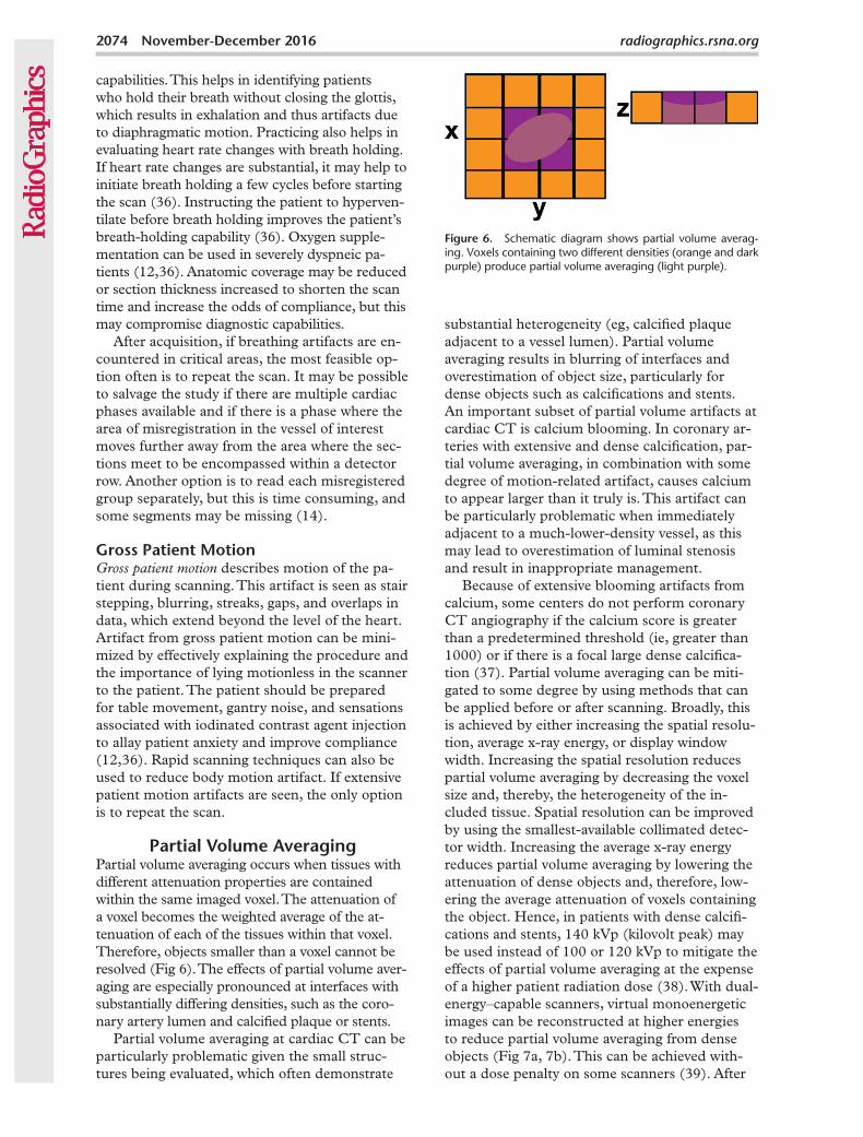
Figure 6. Schematic diagram shows partial volume averag-ing. Voxels containing two different densities (orange and dark purple) produce partial volume averaging (light purple).
capabilities. This helps in identifying patients who hold their breath without closing the glottis, which results in exhalation and thus artifacts due to diaphragmatic motion. Practicing also helps in evaluating heart rate changes with breath holding. If heart rate changes are substantial, it may help to initiate breath holding a few cycles before starting the scan (36). Instructing the patient to hyperven-tilate before breath holding improves the patient’s breath-holding capability (36). Oxygen supple-mentation can be used in severely dyspneic pa-tients (12,36). Anatomic coverage may be reduced or section thickness increased to shorten the scan time and increase the odds of compliance, but this may compromise diagnostic capabilities.
After acquisition, if breathing artifacts are en-countered in critical areas, the most feasible op-tion often is to repeat the scan. It may be possible to salvage the study if there are multiple cardiac phases available and if there is a phase where the area of misregistration in the vessel of interest moves further away from the area where the sec-tions meet to be encompassed within a detector row. Another option is to read each misregistered group separately, but this is time consuming, and some segments may be missing (14).
Gross Patient MotionGross patient motion describes motion of the pa-tient during scanning. This artifact is seen as stair stepping, blurring, streaks, gaps, and overlaps in data, which extend beyond the level of the heart. Artifact from gross patient motion can be mini-mized by effectively explaining the procedure and the importance of lying motionless in the scanner to the patient. The patient should be prepared for table movement, gantry noise, and sensations associated with iodinated contrast agent injection to allay patient anxiety and improve compliance (12,36). Rapid scanning techniques can also be used to reduce body motion artifact. If extensive patient motion artifacts are seen, the only option is to repeat the scan.
Partial Volume AveragingPartial volume averaging occurs when tissues with different attenuation properties are contained within the same imaged voxel. The attenuation of a voxel becomes the weighted average of the at-tenuation of each of the tissues within that voxel. Therefore, objects smaller than a voxel cannot be resolved (Fig 6). The effects of partial volume aver-aging are especially pronounced at interfaces with substantially differing densities, such as the coro-nary artery lumen and calcified plaque or stents.
Partial volume averaging at cardiac CT can be particularly problematic given the small struc-tures being evaluated, which often demonstrate
substantial heterogeneity (eg, calcified plaque adjacent to a vessel lumen). Partial volume averaging results in blurring of interfaces and overestimation of object size, particularly for dense objects such as calcifications and stents. An important subset of partial volume artifacts at cardiac CT is calcium blooming. In coronary ar-teries with extensive and dense calcification, par-tial volume averaging, in combination with some degree of motion-related artifact, causes calcium to appear larger than it truly is. This artifact can be particularly problematic when immediately adjacent to a much-lower-density vessel, as this may lead to overestimation of luminal stenosis and result in inappropriate management.
Because of extensive blooming artifacts from calcium, some centers do not perform coronary CT angiography if the calcium score is greater than a predetermined threshold (ie, greater than 1000) or if there is a focal large dense calcifica-tion (37). Partial volume averaging can be miti-gated to some degree by using methods that can be applied before or after scanning. Broadly, this is achieved by either increasing the spatial resolu-tion, average x-ray energy, or display window width. Increasing the spatial resolution reduces partial volume averaging by decreasing the voxel size and, thereby, the heterogeneity of the in-cluded tissue. Spatial resolution can be improved by using the smallest-available collimated detec-tor width. Increasing the average x-ray energy reduces partial volume averaging by lowering the attenuation of dense objects and, therefore, low-ering the average attenuation of voxels containing the object. Hence, in patients with dense calcifi-cations and stents, 140 kVp (kilovolt peak) may be used instead of 100 or 120 kVp to mitigate the effects of partial volume averaging at the expense of a higher patient radiation dose (38). With dual-energy–capable scanners, virtual monoenergetic images can be reconstructed at higher energies to reduce partial volume averaging from dense objects (Fig 7a, 7b). This can be achieved with-out a dose penalty on some scanners (39). After
RG • Volume 36 Number 7 Kalisz et al 2075
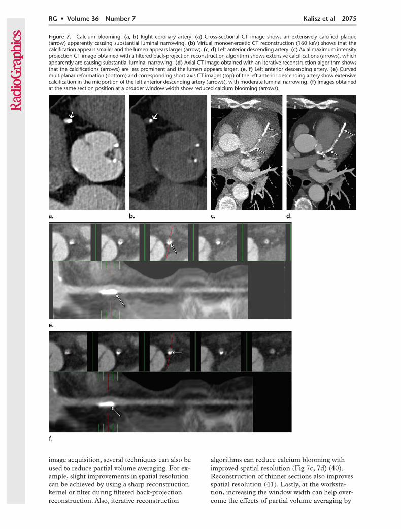
image acquisition, several techniques can also be used to reduce partial volume averaging. For ex-ample, slight improvements in spatial resolution can be achieved by using a sharp reconstruction kernel or filter during filtered back-projection reconstruction. Also, iterative reconstruction
algorithms can reduce calcium blooming with improved spatial resolution (Fig 7c, 7d) (40). Reconstruction of thinner sections also improves spatial resolution (41). Lastly, at the worksta-tion, increasing the window width can help over-come the effects of partial volume averaging by
Figure 7. Calcium blooming. (a, b) Right coronary artery. (a) Cross-sectional CT image shows an extensively calcified plaque (arrow) apparently causing substantial luminal narrowing. (b) Virtual monoenergetic CT reconstruction (160 keV) shows that the calcification appears smaller and the lumen appears larger (arrow). (c, d) Left anterior descending artery. (c) Axial maximum intensity projection CT image obtained with a filtered back-projection reconstruction algorithm shows extensive calcifications (arrows), which apparently are causing substantial luminal narrowing. (d) Axial CT image obtained with an iterative reconstruction algorithm shows that the calcifications (arrows) are less prominent and the lumen appears larger. (e, f) Left anterior descending artery. (e) Curved multiplanar reformation (bottom) and corresponding short-axis CT images (top) of the left anterior descending artery show extensive calcification in the midportion of the left anterior descending artery (arrows), with moderate luminal narrowing. (f) Images obtained at the same section position at a broader window width show reduced calcium blooming (arrows).

2076 November-December 2016 radiographics.rsna.org
expanding the number of gray-scale levels used to display Hounsfield unit values and allowing better differentiation of adjacent regions with large Hounsfield unit differences (Fig 7e, 7f).
Beam HardeningX-ray beams produced at CT are not of a single energy but rather are composed of photons with a spectrum of energies. As these polyenergetic beams pass through an object, low-energy x-rays are preferentially attenuated. The resultant x-ray beam is thus “hardened” with a higher average energy than the beam entering the object (42). The effect of beam hardening is magnified when an x-ray encounters highly attenuating materials such as metal (clips, markers, and wires), bone, or iodinated contrast material, as well as high-con-trast interfaces. As the beam becomes harder after passing through these high-attenuating objects, it better penetrates the tissues beyond the high-attenuating objects, and therefore the recorded detector signal is higher than would have otherwise been recorded along that x-ray path. This causes the reconstruction algorithm to incorrectly assign lower CT attenuation values along this path.
The resultant images demonstrate dark spots or streaks behind or adjacent to the dense object, with surrounding bright streaks. Typically, beam harden-ing adjacent to a calcified plaque results in low at-tenuation that may simulate a noncalcified plaque. This resembles motion artifact as discussed earlier, but unlike motion artifact, beam-hardening artifact does not change with different cardiac phases. Occasionally, beam hardening can be seen behind low-attenuating structures such as air bubbles in the main pulmonary artery or mediastinum after sur-gery (Fig 8a), which may limit the ability to evalu-ate adjacent coronary bypass grafts (12).
Various factors throughout the image acquisi-tion process can be altered to help eliminate or reduce beam hardening. Starting at x-ray genera-tion, increasing the average x-ray energy results in a “harder” beam with fewer low-energy photons able to be attenuated by dense structures. Tube potentials up to 140 kVp can be used, although this may result in a higher radiation dose. With special scanner types, dual-energy data can be acquired and virtual monoenergetic images generated at high energies without an additional radiation dose (43) (Fig 8b, 8c). Dual-energy scans also allow bet-ter separation of calcium from iodine, generating calcium-free angiograms for improved assessment of the lumen (8) (Fig 8c, 8d). Iterative reconstruc-tion has been shown to decrease beam-hardening artifact in some instances (44). After x-ray genera-tion, beam filtration can be used to “preharden” the beam to reduce the number of low-energy photons reaching the patient. In addition, detec-
tor calibration can be tailored to beam-hardening effects occurring at different body regions in the patient. X-ray interaction with the patient can also be modified to reduce beam hardening. Specifically, patient repositioning and gantry tilt can be used to avoid high-attenuation areas that may lead to beam hardening. Also, modifying contrast mate-rial delivery protocols can reduce beam hardening from dense areas of iodinated contrast material. For example, beam-hardening artifact is frequently seen because of the presence of dense undiluted contrast material in the superior vena cava and right atrium at the time of scanning (Fig 8d). This may be pre-vented by using a saline flush after contrast material delivery, which allows washout of contrast material from the superior vena cava and reduces the density of contrast material and the resultant beam-hard-ening effects (Fig 8e). In addition, reconstruction algorithms can be employed that use interpolation techniques to substitute over-range values in at-tenuation profiles and thus reduce the appearance of beam hardening (44).
Metal or Streak ArtifactThe appearance of metal at CT may be com-plex because of the multiple sources of artifacts. Metal artifacts are related to the density of the metal itself as well as the effects of metallic edges at interfaces with lower-attenuating tissues. The attenuation of metallic objects is beyond the normal dynamic range of CT values. This results in incomplete attenuation profiles that cannot be adequately reconstructed, resulting in a characteristic streak artifact of intervening bright and dark streaks (Fig 9a). This artifact can be compounded by beam-hardening and partial volume artifacts (Fig 9b). Furthermore, metal edges can cause additional streak artifacts from undersampling and motion (42). Undersampling results from too large an interval between pro-jections leading to data misregistration, and it is more pronounced about sharp and small objects (45). Although undersampling is not unique to metallic objects, it is often more visible because the undersampling artifact is of a higher magni-tude. Metal artifacts tend to be more pronounced with higher–atomic number metals. In the heart, these artifacts generally arise from metallic stents, pacemaker or implantable cardioverter-defibrilla-tor devices and leads, and surgical clips.
Reduction of metal artifacts involves methods of correcting each of the contributing causes. The beam-hardening component can be reduced by increasing the applied tube potential for a standard single-energy scan or by creating virtual high-monoenergetic images from a dual-energy scan. Partial volume averaging can be minimized by increasing spatial resolution through the meth-

RG • Volume 36 Number 7 Kalisz et al 2077
ods described previously. In addition, dedicated iterative metal reduction reconstruction algo-rithms can be used to further “smooth” the data and reduce metal artifacts (46).
Quantum MottleQuantum mottle (CT noise) occurs secondary to low photon counts reaching the detectors and leading to a larger Poisson error (42). When fewer photons are absorbed, the image noise
increases. Although noise is not an artifact but a basic image characteristic, we have included this because of its significance to image quality and because it must be considered in optimiz-ing image protocols, including steps to reduce artifacts. Noise appears as an irregular granular pattern in the image, sometimes with random, thin, alternating bright and dark streaks appear-ing preferentially along the direction of greatest attenuation. The most common cause of image
Figure 8. Beam-hardening artifact. (a) Axial CT image shows beam-hardening artifact (arrow) adjacent to an air bubble in the main pulmonary artery. (b, c) Conventional 120-kVp axial CT image (b) shows multiple hypoattenuat-ing areas (arrow in b) in the subendocardial region of the left ventricle that could represent either beam hardening or ischemia. On an 80-keV virtual monoenergetic reconstruc-tion (c), the hypoattenuating areas were eliminated (arrow in c), indicating that they are artifacts. (d, e) Axial CT im-age (d) shows beam-hardening artifact from dense contrast material within the superior vena cava (arrow in d). On a subsequent axial CT image (e), the finding was eliminated (arrow in e) by following the contrast agent bolus with a saline flush.

2078 November-December 2016 radiographics.rsna.org
Figure 9. Metal or streak artifact. (a) Axial cardiac CT image shows metallic artifact (arrow) from a prosthetic aortic valve. (b) Axial cardiac CT image shows a cluster of metallic artifacts (arrows) from cardiac pacemaker leads in the right atrium.
noise is large patient size. In obese patients, given the overall elliptical shape of the thorax cross section, noise is often greatest in the lateral dimension (47). In nonobese patients, noise streaking is through the mediastinum along the anteroposterior direction.
As it is principally a problem of too few photons, image noise is generally corrected by increasing photon counts. This can be done by increasing the tube potential or tube current (Fig 10a, 10b), although this will lead to an increased patient radiation dose. The radiation dose can be optimized by using tube current modula-tion, which selectively increases the dose in areas with high attenuation, and bow-tie filters, which provide a higher dose in the center of the field of view (48,49). Unlike noncardiac CT, where noise depends on pitch, in cardiac CT noise depends only on tube current–time product and does not depend on pitch, although the radia-tion dose is inversely proportional to the pitch. Hence, at fast rotation speeds, which require a lower pitch than slow rotation speeds, the noise is higher and a higher radiation dose is required to maintain equivalent noise (50). Conversely, by using a slower gantry rotation time, the noise may be lowered, albeit at the cost of lower temporal resolution. In addition, optimal patient position-ing, including moving the patient’s arms out of the scanned volume and confining the breasts in the anterior thorax, can also reduce image noise (42). Increasing the reconstructed section thick-ness of images also reduces noise (Fig 10c, 10d) because more detected photons will be included in each voxel, but this compromises spatial resolution. A softer reconstruction kernel reduces
noise at the expense of sharpness and spatial resolution. Iterative reconstruction techniques have also been shown to reduce noise, with progressively improved noise reduction at higher iterative levels (Fig 10e, 10f) (51). Unlike filtered back-projection, where noise and image quality worsen with lower radiation dose, with iterative reconstruction, noise increases only slightly but resolution worsens. However, at higher levels of iterative reconstruction, noise clusters into pixels of uniform Hounsfield units, giving a “plastic” appearance (52). However, unique artifacts and undesired appearances have been reported with use of various iterative reconstruction techniques. For example, a pixelated steplike appearance at tissue interfaces has been seen with the adaptive statistical iterative reconstruction (ASIR) method (53), while other methods have been associated with edge-definition artifacts (54). However, the presence of these potential additional artifacts has not yet been shown to produce clinically significant image compromise. Window-level wid-ening and use of higher window levels may aid in interpretation (14). A higher volume and density of contrast agent injection in large patients are also useful in increasing the contrast-to-noise ratio. CT should be avoided in morbidly obese patients with stents, extensive calcifications, or surgical clips, as these artifacts are difficult to overcome.
Slab or Banding ArtifactSlab or banding artifacts result from acquisi-tion of image sections during different phases of contrast enhancement and reflect slight changes in contrast enhancement over the course of data

RG • Volume 36 Number 7 Kalisz et al 2079
Figure 10. Quantum mottle. (a, b) Axial cardiac CT image obtained with a tube current–time product of 300 mAs per section (a) shows noise from quantum mottle artifact, which was reduced on the axial CT image in b after repeat scanning with a tube current–time product of 700 mAs per section. (c, d) Axial CT image with a 0.9-mm section thickness (c) shows extensive noise, which was reduced after increasing the section thickness to 3 mm (d). (e, f) Curved multiplanar reformatted cardiac CT image obtained with a filtered back-projection algorithm (e) shows quantum mottle artifact, which is substantially reduced on the image obtained with itera-tive reconstruction (f).

2080 November-December 2016 radiographics.rsna.org
acquisition. Images display thick bands of varying contrast enhancement that are most apparent in the sagittal and coronal planes or in oblique planes that are orthogonal to the xy plane (Fig 11). In general, banding is more pronounced when data are acquired over a longer body portion and when the time between acquisition of imaging sections is longer (ie, spans more heartbeats) be-cause of the time required for the table to move to the next z-axis position. Therefore, increased z-axis coverage may result in increased band-ing artifact. Using wide–detector array scanners and high-pitch helical mode can enable image acquisition of the entire heart within one heart-beat, thus shortening the scan time sufficiently to largely avoid banding artifacts. Maintaining ho-mogeneous levels of contrast enhancement in the arterial system during acquisition will minimize or eliminate banding in the aorta, left ventricle, and coronary arteries.
Poor Contrast EnhancementPoor contrast enhancement can result from a wide variety of causes, ranging from technique- to patient-specific causes. Improper contrast agent selection and injection parameters such as volumes, densities, or flow rates that are too low can produce suboptimal enhancement. Contrast material extravasation can also reduce the deliv-ered contrast agent volume. Inadequate coverage of the area of interest as well as inaccurate con-figuration of bolus tracking parameters resulting in suboptimal timing may also contribute to poor contrast enhancement. In addition, impaired blood circulation due to heart failure, pulmonary hypertension, valvar disease, and Valsalva maneu-ver can negatively affect delivery of contrast ma-terial to the heart and coronary arteries. Obesity also results in suboptimal contrast enhancement.
Regardless of cause, poor contrast enhance-ment leads to a low contrast-to-noise ratio, with particularly poor visualization of the coronary arteries. Suboptimal contrast enhancement has been associated with inaccurate coronary stenosis assessment at coronary CT angiography (55).
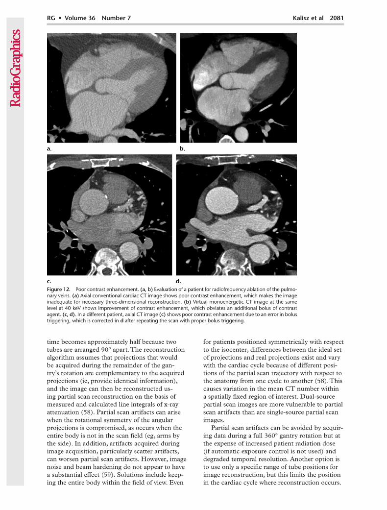
Many steps can be taken before scanning to improve the probability of adequate contrast en-hancement. Contrast agent volume, iodine density, and most importantly the flow rate should be ad-justed for the patient’s body habitus as well as the type of scan. However, contrast agent volume and/or iodine density may be limited by the patient’s renal function. In these cases, it may be useful to lower the tube potential during single-energy CT to increase the attenuation of the iodine signal. With dual-energy CT, virtual monoenergetic im-ages can be created at low energies to boost the iodine signal (Fig 12a, 12b) (56). Scan timing relative to contrast agent injection should also be tailored to the patient to optimize contrast en-hancement. This includes proper placement of a region of interest and triggering the scan start on the basis of patient hemodynamics (Fig 12c, 12d). Use of a timing bolus instead of bolus tracking can be particularly helpful for coronary artery imaging in patients with abnormal left or right ventricular functions, significant valvular disease, or congeni-tal heart disease (57). However, this increases the contrast agent volume and overall scanning time.
Partial Scan ArtifactPartial scan reconstruction algorithms are used at cardiac CT to improve the temporal resolu-tion by a factor of two, by using only projections acquired during partial rotation of the gantry. For single-source scanners, the time required becomes the time to rotate the tube 180° plus the fan angle. For dual-source scanners, coverage
Figure 11. Slab artifact. Sag-ittal reformatted cardiac CT image shows horizontal slabs or bands of varying contrast at-tenuation (arrows). This artifact can be avoided by reducing the number of cardiac cycles used to perform the scan, maintain-ing homogeneous levels of contrast enhancement, or us-ing a fast scanner.
RG • Volume 36 Number 7 Kalisz et al 2081
time becomes approximately half because two tubes are arranged 90° apart. The reconstruction algorithm assumes that projections that would be acquired during the remainder of the gan-try’s rotation are complementary to the acquired projections (ie, provide identical information), and the image can then be reconstructed us-ing partial scan reconstruction on the basis of measured and calculated line integrals of x-ray attenuation (58). Partial scan artifacts can arise when the rotational symmetry of the angular projections is compromised, as occurs when the entire body is not in the scan field (eg, arms by the side). In addition, artifacts acquired during image acquisition, particularly scatter artifacts, can worsen partial scan artifacts. However, image noise and beam hardening do not appear to have a substantial effect (59). Solutions include keep-ing the entire body within the field of view. Even
for patients positioned symmetrically with respect to the isocenter, differences between the ideal set of projections and real projections exist and vary with the cardiac cycle because of different posi-tions of the partial scan trajectory with respect to the anatomy from one cycle to another (58). This causes variation in the mean CT number within a spatially fixed region of interest. Dual-source partial scan images are more vulnerable to partial scan artifacts than are single-source partial scan images.
Partial scan artifacts can be avoided by acquir-ing data during a full 360° gantry rotation but at the expense of increased patient radiation dose (if automatic exposure control is not used) and degraded temporal resolution. Another option is to use only a specific range of tube positions for image reconstruction, but this limits the position in the cardiac cycle where reconstruction occurs.
Figure 12. Poor contrast enhancement. (a, b) Evaluation of a patient for radiofrequency ablation of the pulmo-nary veins. (a) Axial conventional cardiac CT image shows poor contrast enhancement, which makes the image inadequate for necessary three-dimensional reconstruction. (b) Virtual monoenergetic CT image at the same level at 40 keV shows improvement of contrast enhancement, which obviates an additional bolus of contrast agent. (c, d). In a different patient, axial CT image (c) shows poor contrast enhancement due to an error in bolus triggering, which is corrected in d after repeating the scan with proper bolus triggering.

2082 November-December 2016 radiographics.rsna.org
Alternatively, synchronizing gantry rotation with the ECG signal can sometimes reduce the artifact by forcing the position of the x-ray tube to cor-respond to the same cardiac phase (58).
Artifacts from Overlapping Structures
Occasionally, high-attenuation artifacts can be caused by overlapping structures that are adjacent to the coronary arteries, such as the left atrial appendage or coronary veins. These artifacts may obscure the adjacent coronary artery, particularly the proximal portions of left coronary arteries, on maximum intensity projection images, making evaluation difficult. They can be reduced by limit-ing motion-related artifacts, in addition to using an optimized reconstruction window (if data are available from acquisition) (12). Use of thin axial and oblique multiplanar reconstructed images can be considered for better delineation of coronary arteries among overlapping structures.
ConclusionArtifacts are commonly encountered at cardiac CT and are due to a wide spectrum of causes that range from patient-specific to scanner- and technique-specific issues. Left uncorrected, these artifacts may significantly degrade image qual-ity and compromise image interpretation. With proper planning and scan parameter modifica-tions, many of these artifacts can be avoided or significantly reduced, although certain trade-offs may be required.
Disclosures of Conflicts of Interest.—S.A. Activities related to the present article: disclosed no relevant relationships. Activities not related to the present article: royalties from Elsevier and Amir-sys, institutional research agreement with Philips Healthcare and Siemens Healthineers. Other activities: disclosed no rel-evant relationships. S.H. Activities related to the present article: disclosed no relevant relationships. Activities not related to the present article: disclosed no relevant relationships. Other activi-ties: employed by Philips Healthcare. P.R. Activities related to the present article: disclosed no relevant relationships. Activi-ties not related to the present article: honoraria, speaker fees, and institutional research support from Philips Healthcare. Other activities: disclosed no relevant relationships.
References 1. Taylor AJ, Cerqueira M, Hodgson JM, et al. ACCF/SCCT/
ACR/AHA/ASE/ASNC/NASCI/SCAI/SCMR 2010 ap-propriate use criteria for cardiac computed tomography: a report of the American College of Cardiology Foundation Appropriate Use Criteria Task Force, the Society of Cardio-vascular Computed Tomography, the American College of Radiology, the American Heart Association, the American Society of Echocardiography, the American Society of Nuclear Cardiology, the North American Society for Cardiovascular Imaging, the Society for Cardiovascular Angiography and Interventions, and the Society for Cardiovascular Magnetic Resonance. J Am Coll Cardiol 2010;56(22):1864–1894.
2. Tops LF, Krishnàn SC, Schuijf JD, Schalij MJ, Bax JJ. Non-coronary applications of cardiac multidetector row computed tomography. JACC Cardiovasc Imaging 2008;1(1):94–106.
3. Nasis A, Mottram PM, Cameron JD, Seneviratne SK. Current and evolving clinical applications of multidetector cardiac CT in assessment of structural heart disease. Radiol-ogy 2013;267(1):11–25.
4. Danad I, Fayad ZA, Willemink MJ, Min JK. New applica-tions of cardiac computed tomography: dual-energy, spectral, and molecular CT imaging. JACC Cardiovasc Imaging 2015;8(6):710–723.
5. Achenbach S, Marwan M, Ropers D, et al. Coronary com-puted tomography angiography with a consistent dose below 1 mSv using prospectively electrocardiogram-triggered high-pitch spiral acquisition. Eur Heart J 2010;31(3): 340–346.
6. Mahesh M, Cody DD. Physics of cardiac imaging with multiple-row detector CT. RadioGraphics 2007;27(5): 1495–1509.
7. Wang Y, Vidan E, Bergman GW. Cardiac motion of coro-nary arteries: variability in the rest period and implications for coronary MR angiography. Radiology 1999;213(3): 751–758.
8. Hassan A, Nazir SA, Alkadhi H. Technical challenges of coronary CT angiography: today and tomorrow. Eur J Radiol 2011;79(2):161–171.
9. Meng L, Cui L, Cheng Y, et al. Effect of heart rate and coronary calcification on the diagnostic accuracy of the dual-source CT coronary angiography in patients with suspected coronary artery disease. Korean J Radiol 2009;10 (4):347–354.
10. Dewey M, Vavere AL, Arbab-Zadeh A, et al. Patient char-acteristics as predictors of image quality and diagnostic accuracy of MDCT compared with conventional coronary angiography for detecting coronary artery stenoses: CORE-64 Multicenter International Trial. AJR Am J Roentgenol 2010;194(1):93–102.
11. Stolzmann P, Goetti RP, Maurovich-Horvat P, et al. Predic-tors of image quality in high-pitch coronary CT angiography. AJR Am J Roentgenol 2011;197(4):851–858.
12. Choi HS, Choi BW, Choe KO, et al. Pitfalls, artifacts, and remedies in multi–detector row CT coronary angiography. RadioGraphics 2004;24(3):787–800.
13. Achenbach S, Ropers D, Holle J, Muschiol G, Daniel WG, Moshage W. In-plane coronary arterial motion velocity: mea-surement with electron-beam CT. Radiology 2000;216(2): 457–463.
14. Lesser JR, Flygenring BJ, Knickelbine T, Longe T, Schwartz RS. Practical approaches to overcoming artifacts in coronary CT angiography. J Cardiovasc Comput Tomogr 2009;3(1): 4–15.
15. Ghostine S, Caussin C, Daoud B, et al. Non-invasive detec-tion of coronary artery disease in patients with left bundle branch block using 64-slice computed tomography. J Am Coll Cardiol 2006;48(10):1929–1934.
16. Herzog C, Arning-Erb M, Zangos S, et al. Multi–detector row CT coronary angiography: influence of reconstruc-tion technique and heart rate on image quality. Radiology 2006;238(1):75–86.
17. Mahabadi AA, Achenbach S, Burgstahler C, et al. Safety, efficacy, and indications of b-adrenergic receptor blockade to reduce heart rate prior to coronary CT angiography. Radiol-ogy 2010;257(3):614–623.
18. Abbara S, Arbab-Zadeh A, Callister TQ, et al. SCCT guide-lines for performance of coronary computed tomographic angiography: a report of the Society of Cardiovascular Computed Tomography Guidelines Committee. J Cardiovasc Comput Tomogr 2009;3(3):190–204.
19. Hsiao EM, Rybicki FJ, Steigner M. CT coronary angiography: 256-slice and 320-detector row scanners. Curr Cardiol Rep 2010;12(1):68–75.
20. Sun G, Li M, Jiang XS, et al. 320-detector row CT coronary angiography: effects of heart rate and heart rate variability on image quality, diagnostic accuracy and radiation exposure. Br J Radiol 2012;85(1016):e388–e394.
21. Rybicki FJ, Otero HJ, Steigner ML, et al. Initial evaluation of coronary images from 320-detector row computed tomog-raphy. Int J Cardiovasc Imaging 2008;24(5):535–546.
22. Qin J, Liu LY, Fang Y, et al. 320-detector CT coronary angi-ography with prospective and retrospective electrocardiogram

RG • Volume 36 Number 7 Kalisz et al 2083
gating in a single heartbeat: comparison of image quality and radiation dose. Br J Radiol 2012;85(1015):945–951.
23. Stassi D, Dutta S, Ma H, et al. Automated selection of the optimal cardiac phase for single-beat coronary CT angiog-raphy reconstruction. Med Phys 2016;43(1):324.
24. Achenbach S, Goroll T, Seltmann M, et al. Detection of coronary artery stenoses by low-dose, prospectively ECG-triggered, high-pitch spiral coronary CT angiography. JACC Cardiovasc Imaging 2011;4(4):328–337.
25. Deseive S, Pugliese F, Meave A, et al. Image quality and radiation dose of a prospectively electrocardiography-triggered high-pitch data acquisition strategy for coronary CT angiography: the multicenter, randomized PROTEC-TION IV study. J Cardiovasc Comput Tomogr 2015;9(4): 278–285.
26. Achenbach S, Marwan M, Schepis T, et al. High-pitch spiral acquisition: a new scan mode for coronary CT angiography. J Cardiovasc Comput Tomogr 2009;3(2):117–121.
27. Schöndube H, Allmendinger T, Stierstorfer K, Bruder H, Flohr T. Temporal resolution and motion artifacts in single-source and dual-source cardiac CT. Med Phys 2013;40(3):031112.
28. Flohr TG, McCollough CH, Bruder H, et al. First perfor-mance evaluation of a dual-source CT (DSCT) system. Eur Radiol 2006;16(2):256–268.
29. Halliburton SS, Rajiah P. Cardiac CT scanner technology: what is new and what is next? Curr Cardiovasc Imaging Rep 2016;9:8.
30. Ranallo FN, Szczykutowicz T. The correct selection of pitch for optimal CT scanning: avoiding common misconceptions. J Am Coll Radiol 2015;12(4):423–424.
31. Machida H, Tanaka I, Fukui R, et al. Current and novel imaging techniques in coronary CT. RadioGraphics 2015;35(4):991–1010.
32. Leipsic J, Labounty TM, Hague CJ, et al. Effect of a novel vendor-specific motion-correction algorithm on image quality and diagnostic accuracy in persons undergoing coronary CT angiography without rate-control medications. J Cardiovasc Comput Tomogr 2012;6(3):164–171.
33. Min JK, Arsanjani R, Kurabayashi S, et al. Rationale and design of the ViCTORY (Validation of an Intracycle CT Motion CORrection Algorithm for Diagnostic AccuracY) trial. J Cardiovasc Comput Tomogr 2013;7(3):200–206.
34. Takayanagi T, Sano T, Kondo T, et al. Clinical usefulness of low tube current scanning with full reconstruction and automatic patient motion correction (APMC) reconstruction in a prospective ECG-gated coronary CT angiography using 320-row area detector CT [in Japanese]. Nihon Hoshasen Gijutsu Gakkai Zasshi 2015;71(3):237–245.
35. Kröpil P, Rojas CA, Ghoshhajra B, et al. Prospectively ECG-triggered high-pitch spiral acquisition for cardiac CT angiography in routine clinical practice: initial results. J Thorac Imaging 2012;27(3):194–201.
36. Halliburton SS, Abbara S. Practical tips and tricks in car-diovascular computed tomography: patient preparation for optimization of cardiovascular CT data acquisition. J Cardiovasc Comput Tomogr 2007;1(1):62–65.
37. Hecht HS, Bhatti T. How much calcium is too much cal-cium for coronary computerized tomographic angiography? J Cardiovasc Comput Tomogr 2008;2(3):183–187.
38. Yu L, Leng S, McCollough CH. Dual-energy CT-based monochromatic imaging. AJR Am J Roentgenol 2012;199 (5 suppl):S9–S15.
39. Henzler T, Fink C, Schoenberg SO, Schoepf UJ. Dual-energy CT: radiation dose aspects. AJR Am J Roentgenol 2012;199 (5 suppl):S16–S25.
40. Li K, Garrett J, Ge Y, Chen GH. Statistical model based iterative reconstruction (MBIR) in clinical CT systems. II. Experimental assessment of spatial resolution performance. Med Phys 2014;41(7):071911.
41. Kumamaru KK, Hoppel BE, Mather RT, Rybicki FJ. CT angiography: current technology and clinical use. Radiol Clin North Am 2010;48(2):213–235, vii.
42. Boas FE, Fleischmann D. CT artifacts: causes and reduction techniques. Imaging Med 2012;4(2):229–240.
43. Stolzmann P, Winklhofer S, Schwendener N, Alkadhi H, Thali MJ, Ruder TD. Monoenergetic computed tomogra-phy reconstructions reduce beam hardening artifacts from dental restorations. Forensic Sci Med Pathol 2013;9(3): 327–332.
44. Hsieh J, Molthen RC, Dawson CA, Johnson RH. An iterative approach to the beam hardening correction in cone beam CT. Med Phys 2000;27(1):23–29.
45. Barrett JF, Keat N. Artifacts in CT: recognition and avoid-ance. RadioGraphics 2004;24(6):1679–1691.
46. Zhang X, Wang J, Xing L. Metal artifact reduction in x-ray computed tomography (CT) by constrained optimization. Med Phys 2011;38(2):701–711.
47. Modica MJ, Kanal KM, Gunn ML. The obese emergency patient: imaging challenges and solutions. RadioGraphics 2011;31(3):811–823.
48. Ghoshhajra BB, Engel LC, Károlyi M, et al. Cardiac computed tomography angiography with automatic tube potential selec-tion: effects on radiation dose and image quality. J Thorac Imaging 2013;28(1):40–48.
49. McCollough CH. Re: maximizing dose reductions with cardiac CT. Int J Cardiovasc Imaging 2009;25(6):647.
50. Primak AN, McCollough CH, Bruesewitz MR, Zhang J, Fletcher JG. Relationship between noise, dose, and pitch in cardiac multi–detector row CT. RadioGraphics 2006;26(6): 1785–1794.
51. Thibault JB, Sauer KD, Bouman CA, Hsieh J. A three-dimensional statistical approach to improved image quality for multislice helical CT. Med Phys 2007;34(11): 4526–4544.
52. Singh S, Khawaja RD, Pourjabbar S, Padole A, Lira D, Kalra MK. Iterative image reconstruction and its role in cardiothoracic computed tomography. J Thorac Imaging 2013;28(6):355–367.
53. Willemink MJ, de Jong PA, Leiner T, et al. Iterative recon-struction techniques for computed tomography. I. Technical principles. Eur Radiol 2013;23(6):1623–1631.
54. Nelson RC, Feuerlein S, Boll DT. New iterative reconstruction techniques for cardiovascular computed tomography: how do they work, and what are the advantages and disadvantages? J Cardiovasc Comput Tomogr 2011;5(5):286–292.
55. Yan RT, Miller JM, Rochitte CE, et al. Predictors of inaccu-rate coronary arterial stenosis assessment by CT angiography. JACC Cardiovasc Imaging 2013;6(9):963–972.
56. Scheske JA, O’Brien JM, Earls JP, et al. Coronary artery imaging with single-source rapid kilovolt peak-switching dual-energy CT. Radiology 2013;268(3):702–709.
57. Taylor CM, Blum A, Abbara S. Patient preparation and scanning techniques. Radiol Clin North Am 2010;48(4): 675–686.
58. Primak AN, Dong Y, Dzyubak OP, Jorgensen SM, McCollough CH, Ritman EL. A technical solution to avoid partial scan artifacts in cardiac MDCT. Med Phys 2007;34(12):4726–4737.
59. Tao Y, Speidel M, Szczykutowicz T, Chen GH. Investigation of the potential causes of partial scan artifacts in dynamic CT myocardial perfusion imaging. In: Whiting BR, Hoeschen C, eds. Proceedings of SPIE: medical imaging 2014—physics of medical imaging. Vol 9033. Bellingham, Wash: International Society for Optics and Photonics, 2014; 90332B.
This journal-based SA-CME activity has been approved for AMA PRA Category 1 CreditTM. See www.rsna.org/education/search/RG.