avv om2 1-4-20inairvacuumvalve
TRANSCRIPT
7/29/2019 AVV OM2 1-4-20inAirVacuumValve
http://slidepdf.com/reader/full/avv-om2-1-4-20inairvacuumvalve 1/7
Manual No. A/VV-OM2-1
Val-Matic® 4” -20” Air/Vacuum Valve
With Optional Anti-Slam Valve
Operation, Maintenance andInstallation Manual
INTRODUCTION ....................................... 1RECEIVING AND STORAGE.................... 1DESCRIPTION OF OPERATION .............. 1INSTALLATION......................................... 2VALVE CONSTRUCTION......................... 2MAINTENANCE ........................................ 3TROUBLESHOOTING............................... 3DISASSEMBLY ......................................... 3REASSEMBLY .......................................... 4OPTIONAL ANTI-SLAM VALVE............... 4PARTS & SERVICE................................... 5WARRANTY .............................................. 6
VALVE AND MANUFACTURING CORP.
905 Riverside Dr. ● Elmhurst , IL 60126Phone (630) 941-7600 ● Fax (630) 941-8042
7/29/2019 AVV OM2 1-4-20inAirVacuumValve
http://slidepdf.com/reader/full/avv-om2-1-4-20inairvacuumvalve 2/7
1
VAL-MATIC’S 4” -20” AIR/VACUUM VALVEOPERATION, MAINTENANCE AND INSTALLATION
INTRODUCTIONThis manual will provide you with the informationto properly install and maintain the valve toensure a long service life. The Air/VacuumValve has been designed with stainless steeltrim to give years of trouble free operation. The
Air/vacuum valve is typically mounted on apipeline at the high points or large changes ingrade.
The valve will exhaust large quantities of air during system start-up and allow air to re-enter the line upon system shut down or after a power failure. The valves are needed to maintainpipeline efficiency while providing protection
from adverse pressure condition. The Size,Maximum Working Pressure, and Model No. arestamped on the nameplate for reference.
NOTE: While Air/Vacuum Valves will exhaustlarge quantities of air upon start-up, they will notcontinuously release air during systemoperation. For that function, Air Release Valvesare required.
Also, this valve is not intended for fluidscontaining suspended solids such aswastewater. For wastewater and other high
turbidity applications, use Val-Matic Series 300Wastewater Air/Vacuum Valves.
RECEIVING AND STORAGEInspect valves upon receipt for damage inshipment. Unload all valves carefully to the
ground without dropping. Valves should remaincrated, clean and dry until installed to preventweather related damage. For long-term storage,greater than six months, the rubber surfaces of the seats should be coated with a thin film of FDA approved grease. Do not expose seat tosunlight or ozone for any extended period.
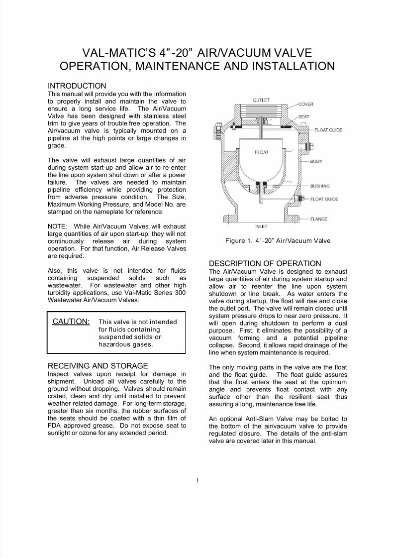
Figure 1. 4” -20” Ai r/Vacuum Valve
DESCRIPTION OF OPERATIONThe Air/Vacuum Valve is designed to exhaustlarge quantities of air during system startup andallow air to reenter the line upon system
shutdown or line break. As water enters thevalve during startup, the float will rise and closethe outlet port. The valve will remain closed untilsystem pressure drops to near zero pressure. Itwill open during shutdown to perform a dualpurpose. First, it eliminates the possibility of avacuum forming and a potential pipelinecollapse. Second, it allows rapid drainage of theline when system maintenance is required.
The only moving parts in the valve are the floatand the float guide. The float guide assuresthat the float enters the seat at the optimum
angle and prevents float contact with anysurface other than the resilient seat thusassuring a long, maintenance free life.
An optional Anti-Slam Valve may be bolted tothe bottom of the air/vacuum valve to provideregulated closure. The details of the anti-slamvalve are covered later in this manual.
CAUTION: This valve is not intendedfor fluids containingsuspended solids or hazardous gases.
7/29/2019 AVV OM2 1-4-20inAirVacuumValve
http://slidepdf.com/reader/full/avv-om2-1-4-20inairvacuumvalve 3/7
2
INSTALLATION The installation of the valve is important for itsproper operation. The valves must be installedat the system high points in the vertical positionwith the inlet down. For pipeline service, a vaultwith freeze protection, adequate screened
venting, and drainage should be provided.During closure, some fluid discharge will occur so vent lines should extend to an open drain for in-plant installations. A shutoff valve should beinstalled below the valve in the event servicing isrequired. A spool piece is required when matingto a wafer butterfly valve.
FLANGED ENDS: Flanged valves should bemated with flat-faced pipe flanges equipped withresilient gaskets. When ring gaskets are used,the bolt material shall be ASTM A307 Grade Bor SAE Grade 2 carbon steel.
Lower the valve over the mating flange usingslings or chains around the valve body.Lubricate the flange bolts or studs and insertthem around the flange. Lightly turn bolts untilgaps are eliminated. The tightening of the boltsshould be done in graduated steps using the
crossover tightening method. Recommendedlubricated torque values, for use with resilientgaskets (75 durometer), are given in Table 1.
If leakage occurs, allow gaskets to absorb fluidand check the bolt torque and leakage after 24hours. Do not exceed bolt rating or crush gasketmore than 50% of its thickness.
ValveSize(in)
BoltDia(in)
Recom.Torque(ft-lbs)
Max.Torque(ft-lbs)
4 5/8 30 90
6 3/4 30 150
8 3/4 40 15010 7/8 45 205
12 7/8 45 205
14 1 80 300
16 1 90 300
18 1 1/8 100 425
20 1 1/8 120 425
Table 1. Flange Bolt Torques
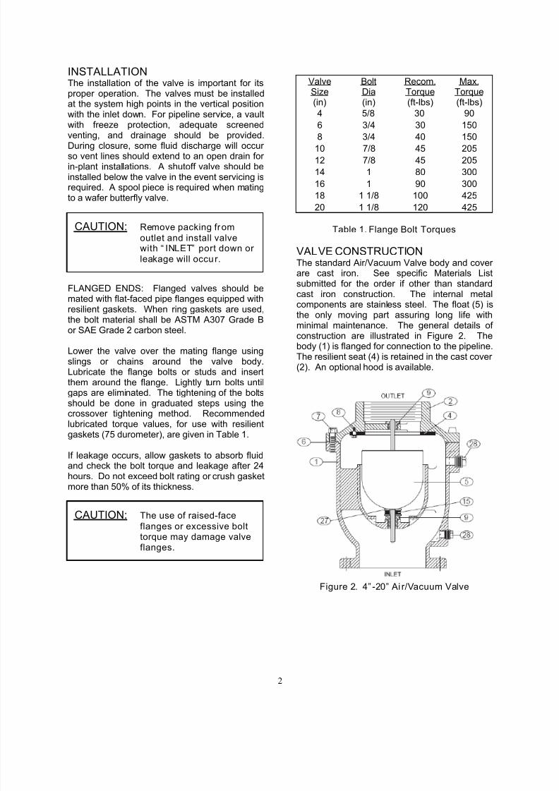
VALVE CONSTRUCTION The standard Air/Vacuum Valve body and cover
are cast iron. See specific Materials Listsubmitted for the order if other than standardcast iron construction. The internal metalcomponents are stainless steel. The float (5) isthe only moving part assuring long life withminimal maintenance. The general details of construction are illustrated in Figure 2. Thebody (1) is flanged for connection to the pipeline.The resilient seat (4) is retained in the cast cover (2). An optional hood is available.
Figure 2. 4” -20” Ai r/Vacuum Valve
CAUTION: Remove packing from
outlet and install valvewith “ INLET” port down or leakage will occur.
CAUTION: The use of raised-face
flanges or excessive bolttorque may damage valveflanges.
7/29/2019 AVV OM2 1-4-20inAirVacuumValve
http://slidepdf.com/reader/full/avv-om2-1-4-20inairvacuumvalve 4/7
3
Item Description Material
1 Body Cast Iron
2 Cover Cast Iron
4 Seat* Buna-N
5 Float* Stainless Steel
6 Gasket* Non-Asbestos
7 Cover Bolt Alloy Steel
8 Retaining Screw Stainless Steel
9 Guide Bushing* Stainless Steel
15 Cushion* Buna-N
23Hood Assembly(optional)
Iron, Steel
27Washer*(8”-20” valves)
Stainless steel
28 Pipe Plug Malleable Iron
*Recommended Spare Part
Table 2. Air/Vacuum Valve Parts List
MAINTENANCE The Air/Vacuum Valve requires no scheduledlubrication or maintenance.
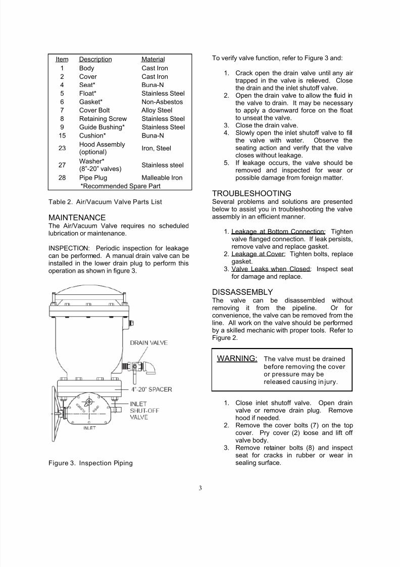
INSPECTION: Periodic inspection for leakagecan be performed. A manual drain valve can beinstalled in the lower drain plug to perform thisoperation as shown in figure 3.
Figure 3. Inspection Piping
To verify valve function, refer to Figure 3 and:
1. Crack open the drain valve until any air trapped in the valve is relieved. Closethe drain and the inlet shutoff valve.
2. Open the drain valve to allow the fluid inthe valve to drain. It may be necessaryto apply a downward force on the floatto unseat the valve.
3. Close the drain valve.4. Slowly open the inlet shutoff valve to fill
the valve with water. Observe theseating action and verify that the valvecloses without leakage.
5. If leakage occurs, the valve should beremoved and inspected for wear or possible damage from foreign matter.
TROUBLESHOOTING Several problems and solutions are presentedbelow to assist you in troubleshooting the valveassembly in an efficient manner.
1. Leakage at Bottom Connection: Tightenvalve flanged connection. If leak persists,remove valve and replace gasket.
2. Leakage at Cover: Tighten bolts, replacegasket.
3. Valve Leaks when Closed: Inspect seatfor damage and replace.
DISSASSEMBLYThe valve can be disassembled withoutremoving it from the pipeline. Or for convenience, the valve can be removed from theline. All work on the valve should be performedby a skilled mechanic with proper tools. Refer toFigure 2.
1. Close inlet shutoff valve. Open drainvalve or remove drain plug. Removehood if needed.
2. Remove the cover bolts (7) on the topcover. Pry cover (2) loose and lift off valve body.
3. Remove retainer bolts (8) and inspectseat for cracks in rubber or wear insealing surface.
WARNING: The valve must be drained
before removing the cover or pressure may bereleased causing in jury.
7/29/2019 AVV OM2 1-4-20inAirVacuumValve
http://slidepdf.com/reader/full/avv-om2-1-4-20inairvacuumvalve 5/7
4
4. Lift float (5) from body. Turn guidebushing (9) to remove it from body (1).
5. Clean and inspect parts. Note: somefloats contain sand for extra weight; if water is detected, replace float.Replace worn parts as necessary andlubricate parts with FDA grease.Remove all foreign matter from bodyand cover.
REASSEMBLY All parts must be cleaned and gasket surfacesshould be cleaned with a stiff wire brush in thedirection of the serrations or machine marks.Worn parts, gaskets and seals should bereplaced during reassembly.
1. Apply thread sealant Loctite 680 toguide bushing threads (9) and threadbushing into body (1).
2. Lay seat (4) over inverted cover with flatsurface directed toward cover. Fastento cover with screws (8). Tightenfasteners per Table 3.
3. Install float (5) through bushing (9).4. Apply a gasket compound such as
Garlock 101-S to both sides of gasket.Lay cover gasket (6) and cover (2) over bolt holes in body (1).
5. Insert lubricated bolts (7) and tighten tothe torques listed in Table 3.
Size Torque (ft-lbs)
1/4" 6
5/16” 11
3/8” 19
7/16” 30
1/2" 45
5/8” 93
3/4" 150
7/8” 202
Table 3. Valve Bolts Torques
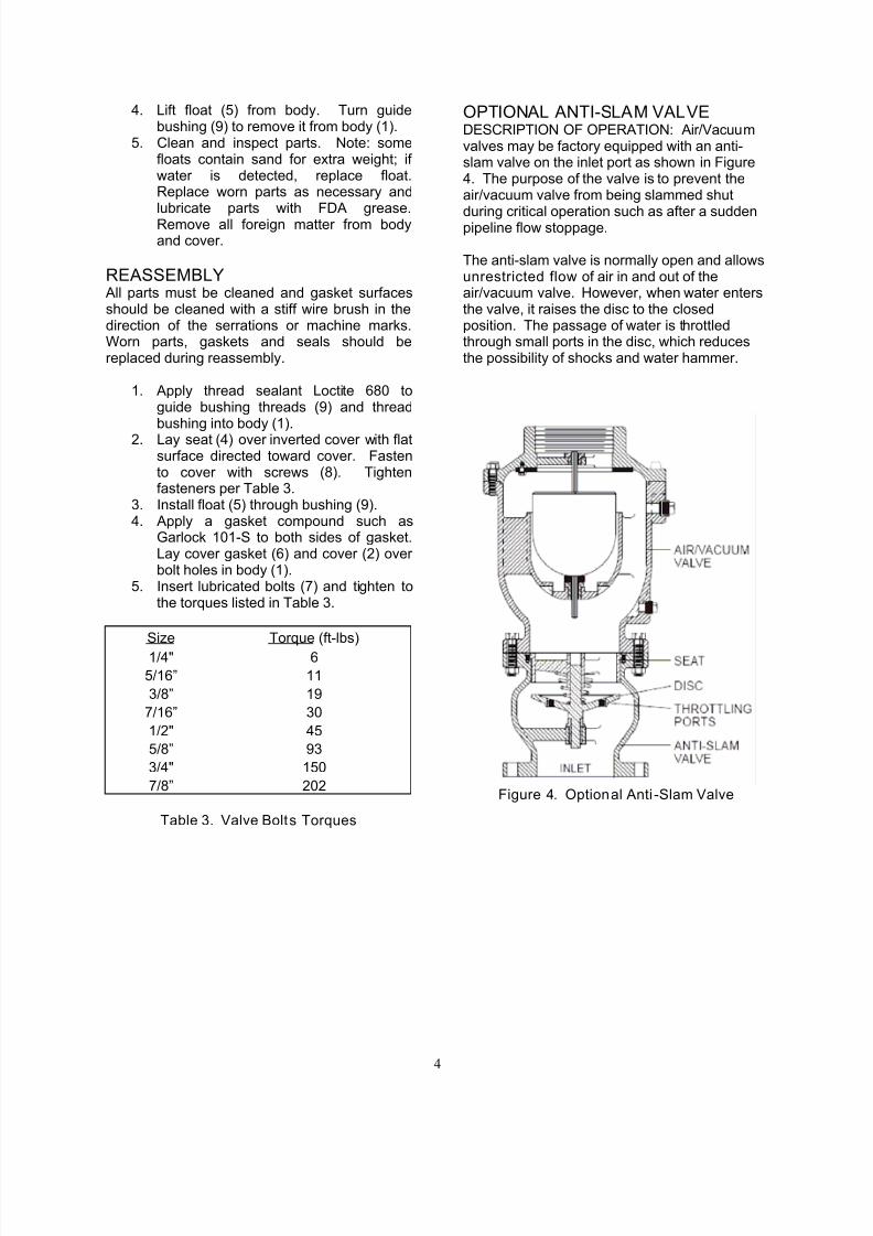
OPTIONAL ANTI-SLAM VALVEDESCRIPTION OF OPERATION: Air/Vacuumvalves may be factory equipped with an anti-slam valve on the inlet port as shown in Figure4. The purpose of the valve is to prevent theair/vacuum valve from being slammed shut
during critical operation such as after a suddenpipeline flow stoppage.
The anti-slam valve is normally open and allowsunrestricted flow of air in and out of theair/vacuum valve. However, when water entersthe valve, it raises the disc to the closedposition. The passage of water is throttledthrough small ports in the disc, which reducesthe possibility of shocks and water hammer.
Figure 4. Optional Anti -Slam Valve
7/29/2019 AVV OM2 1-4-20inAirVacuumValve
http://slidepdf.com/reader/full/avv-om2-1-4-20inairvacuumvalve 6/7
5
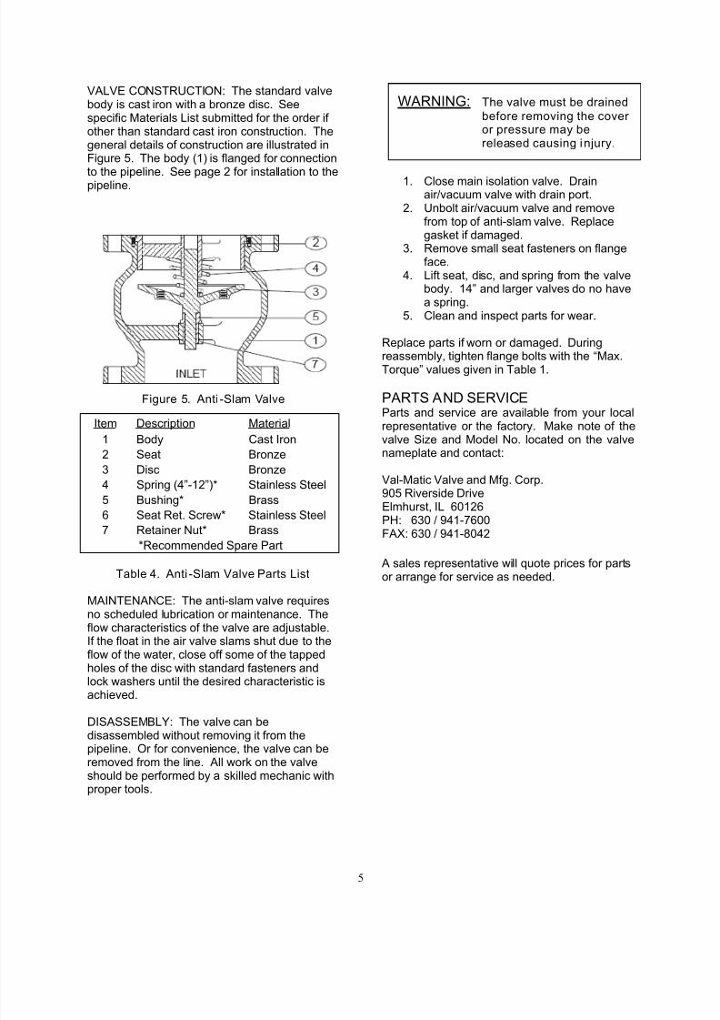
VALVE CONSTRUCTION: The standard valvebody is cast iron with a bronze disc. Seespecific Materials List submitted for the order if other than standard cast iron construction. Thegeneral details of construction are illustrated inFigure 5. The body (1) is flanged for connectionto the pipeline. See page 2 for installation to thepipeline.
Figure 5. Anti -Slam Valve
Table 4. Anti -Slam Valve Parts List
MAINTENANCE: The anti-slam valve requiresno scheduled lubrication or maintenance. Theflow characteristics of the valve are adjustable.If the float in the air valve slams shut due to theflow of the water, close off some of the tappedholes of the disc with standard fasteners andlock washers until the desired characteristic isachieved.
DISASSEMBLY: The valve can bedisassembled without removing it from thepipeline. Or for convenience, the valve can beremoved from the line. All work on the valveshould be performed by a skilled mechanic withproper tools.
1. Close main isolation valve. Drainair/vacuum valve with drain port.
2. Unbolt air/vacuum valve and removefrom top of anti-slam valve. Replacegasket if damaged.
3. Remove small seat fasteners on flangeface.
4. Lift seat, disc, and spring from the valvebody. 14” and larger valves do no havea spring.
5. Clean and inspect parts for wear.
Replace parts if worn or damaged. During
reassembly, tighten flange bolts with the “Max.Torque” values given in Table 1.
PARTS AND SERVICEParts and service are available from your localrepresentative or the factory. Make note of thevalve Size and Model No. located on the valvenameplate and contact:
Val-Matic Valve and Mfg. Corp.905 Riverside DriveElmhurst, IL 60126PH: 630 / 941-7600
FAX: 630 / 941-8042
A sales representative will quote prices for partsor arrange for service as needed.
Item Description Material
1 Body Cast Iron
2 Seat Bronze
3 Disc Bronze
4 Spring (4”-12”)* Stainless Steel
5 Bushing* Brass
6 Seat Ret. Screw* Stainless Steel
7 Retainer Nut* Brass*Recommended Spare Part
WARNING: The valve must be drained
before removing the cover or pressure may bereleased causing injury.
7/29/2019 AVV OM2 1-4-20inAirVacuumValve
http://slidepdf.com/reader/full/avv-om2-1-4-20inairvacuumvalve 7/7
6
VALVE AND MANUFACTURING CORP.
905 Riverside Dr. ● Elmhurst , IL 60126Phone (630) 941-7600 ● Fax (630) 941-8042
LIMITED WARRANTY
All products are warranted to be free of defects in material and workmanship for a period of one year from the date of shipment, subject to the limitations below.
If the purchaser believes a product is defective, the purchaser shall: (a) Notify the manufacturer, state the alleged defectand request permission to return the product; (b) if permission is given, return the product with transportation prepaid. If the product is accepted for return and found to be defective, the manufacturer will, at his discretion, either repair or replacethe product, f.o.b. factory, within 60 days of receipt, or refund the purchase price. Other than to repair, replace or refundas described above, purchaser agrees that manufacturer shall not be liable for any loss, costs, expenses or damages of any kind arising out of the product, its use, installation or replacement, labeling, instructions, information or technical dataof any kind, description of product use, sample or model, warnings or lack of any of the foregoing. NO OTHERWARRANTIES, WRITTEN OR ORAL, EXPRESS OR IMPLIED, INCLUDING THE WARRANTIES OF FITNESS FOR APARTICULAR PURPOSE AND MERCHANTABILITY, ARE MADE OR AUTHORIZED. NO AFFIRMATION OF FACT,PROMISE, DESCRIPTION OF PRODUCT OF USE OR SAMPLE OR MODEL SHALL CREATE ANY WARRANTY FROMMANUFACTURER, UNLESS SIGNED BY THE PRESIDENT OF THE MANUFACTURER. These products are notmanufactured, sold or intended for ersonal, famil or household ur oses.