building novel equipment modules for a commercial …building novel equipment modules for a...
TRANSCRIPT

Building novel equipment modules for a commercial process simulator: the compact plate heat exchanger case.
A.A. Mouza, K.D. Antoniadis, S.V. Paras Chemical Engineering Department, Aristotle University of Thessaloniki, Univ. Box 455, GR54124, Thessaloniki, Greece Fax: +30 2310 996209, e-mail: [email protected], [email protected]
Abstract
Process simulation is already a well-established method for process industry, useful to study the performance of either an individual unit operation or an entire plant. New types of equipment, which are in either an early stage of development or an experimental phase, are normally not included in commercial simulators, due to either lack of generalized de-sign methods or limited interest in the specific piece of equipment, although their perform-ance must be evaluated in conjunction with the available conventional equipment. Aspen Custom Modeler (ACM), which is a feature of the Aspen Plus® Engineering suite, is a con-venient tool for non-experts for creating, editing, and re-using models of process units. Thus, the new equipment can be integrated with the conventional process equipment, in order to study its influence on the overall plant performance.
This work is a case study, where the plate heat exchanger design correlations are in-corporated into an existing process simulator (Aspen Plus®). This type of heat exchanger was selected because it holds significant advantages over conventional equipment and is being rapidly adopted by food, chemical and refrigeration process industries. The paper gives an overview of the experience acquired in the course of the model integration proce-dure into the simulator.

CHISA 2004, 16th INTERNATIONAL CONGRESS OF CHEMICAL AND PROCESS ENGINEERING, PRAGUE Aug. 2004
1. Introduction In recent years, industries are obliged to improve the performance of their plants and
to reduce cost and time for plant development, in order to comply with economic, envi-ronmental and safety constraints. The use of a commercial process simulator has been proved a powerful tool both for the design and optimisation of chemical processes and for the evaluation of alternative designs. Its increasingly expanding application as an easy-to-use tool converts the computer into a virtual plant that can be used as a real alternative to the always expensive studies at pilot plant level.
Despite the fact that the commercial simulators offer a large number of advantages their use is limited to well-established unit operation models (e.g. distillation columns, conventional heat exchangers, reactors). Novel types of equipment, which are in either an early stage of development or an experimental phase, are normally not included in com-mercial simulators, due to either lack of generalized design methods or limited interest in the specific piece of equipment. However, there is need to incorporate novel equipment models in an existing simulator, in order to evaluate their performance in conjunction with the other plant equipment, since new research results slowly find their way into commercial process simulation software. To overcome this problem the majority of the existing simula-tors provide the possibility to import novel equipment models using additional software.
This work is a case study, where a novel piece of equipment, i.e. the compact heat ex-changer, is incorporated into an existing process simulator (Aspen Plus®). In this way the new equipment can be integrated into the process and its influence on overall plant per-formance can be investigated. This paper depicts the experience obtained during the im-plementation of the new model into the simulator.
2. Integrating new equipment in a process simulator In this study the Aspen Plus® is employed. It is a process simulator that uses the block-
oriented approach, where, in order to study a particular unit operation, a set of design equa-tions is implemented. Thus, each block, i.e. set of design equations, is a modelling compo-nent intended to perform a well-defined function, e.g. the simulation of a particular unit operation, or the numerical solution of certain types of optimization problems. This simple and effective approach helps engineers in solving standard flow sheets, but does not suffi-ciently support the solution of more complex problems. This is largely due to the multitude of models required in order to incorporate with sufficient details the numerous processing units encountered, such as multi-phase reactors, membrane processing units, polymeric re-actors. On the other hand, some block-oriented process simulators, such as Aspen Plus®, give the possibility to introduce a novel piece of equipment and connect it to the conven-tional ones by simply importing in the simulator the equations that describe this particular type of equipment. Once the design equations plus the input and output parameters are de-fined, the new equipment can be integrated with conventional process equipment and its influence to the overall plant performance can be studied.
Several methods are provided for introducing new models in Aspen Plus® 11.1. (As-pen Plus Manual, 2001) such as:
• Fortran subroutines, that can be implemented in the simulator in order to perform the calculations and extend the capabilities of Aspen Plus®,
• Excel spreadsheets that can be dynamically linked to the simulator in order to import or export process data
• Models that conform to the CAPE-OPEN (Computer-Aided Process Engineering) standards, which were established with the goal of using process simulation tools de-

CHISA 2004, 16th INTERNATIONAL CONGRESS OF CHEMICAL AND PROCESS ENGINEERING, PRAGUE Aug. 2004
veloped by third parties within any standard chemical process simulation environment. These standards are based on universally recognized software technologies such as COM and CORBA, and are open, multiplatform, uniform and available free of charge (www.co-lan.org). Aspen Plus® provides support for part of the COM specification. (Aspen Plus Manual, 2001).
• Aspen Custom Modeler 11.1 (ACM), a special modelling language supplied by As-pen Technology Inc.
From the aforementioned methods, the one employed in this study, is the ACM which is a feature of the Aspen Plus® Engineering suite. ACM uses an object-oriented modelling language, editors for icons and tasks, and Microsoft Visual Basic for scripts to build simu-lation applications. In this way a block can be built, where the appropriate design equations are introduced and the input/output variables are defined and linked dynamically with other available process equipment (Aspen Plus Manual, 2001). Consequently, ACM can be con-sidered a convenient tool for non-experts for incorporating new process units in the simula-tor, whereas CAPE–OPEN is more suitable for end-users with sound programming experi-ence.
ACM can cope with different kinds of problems such as dynamic, steady state, parame-ter estimation and optimization simulations using an equation-based approach (Aspen Cus-tom ModelerTM Manual, 2001). An important feature of ACM is that it provides direct ac-cess to the Aspen Plus® property database and in this way the physical and chemical prop-erties of the various components involved can be calculated using the numerous property models offered by the simulator. In general the main steps that must be followed in order to implement a specific equipment model into Aspen Plus® using ACM are:
• The design equations that best describe the equipment behaviour must be chosen and the model input and output variables must be decided. The system of equations must have zero degrees of freedom.
• The components that are involved in the simulation model must be declared and saved in an Aspen Properties file, where also the most suitable property calculation method provided by Aspen Plus® is included. This file is used within ACM, where the components should be declared again.
• The variables involved in the equations are declared and assigned to the correspond-ing physical quantity and by default to its base unit.
• The design equations of the new unit operation model are inserted using ACM model-ling language. Unlike conventional programming languages, ACM has no restrictions regarding the form and the solution order of the equations.
• The model input and output streams must be declared and assigned to an input or an output port, respectively. These ports are basically submodels which are added to the new model for dynamic information exchange with other Aspen Plus® blocks. All the variables of the input port are fixed and are assigned the values of the stream con-nected to the port, whereas the variables of the output port are free and are calculated during the simulation. In order to be able to incorporate the new model to Aspen Plus® the C++ compiler must be available.
The new equipment model, after being exported to the Aspen Plus® environment, can be connected to other equipment via the corresponding input/output ports and can be manipu-lated like any other block contained in Aspen Plus® library. It should be mentioned that the components must have identical names in the Aspen Plus® simulation, in the Aspen Proper-ties file and in the ACM model.

CHISA 2004, 16th INTERNATIONAL CONGRESS OF CHEMICAL AND PROCESS ENGINEERING, PRAGUE Aug. 2004
3. Case study: The compact heat exchanger In recent years, the requirement for energy-efficient heat transfer equipment is con-
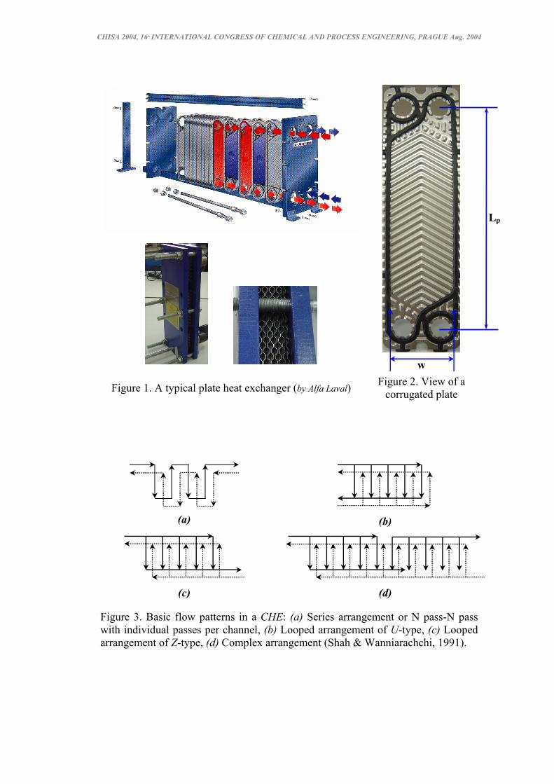
stantly increasing. In the same time the development of novel equipment has been driven by the need for economical, high performance, small in size and lightweight alternatives. The new generation of compact heat exchangers (CHE) complies with the above require-ments. Compact plate heat exchangers comprised of surfaces with special modulations (corrugations) (Figure 1) hold significant advantages over conventional equipment, e.g. large surface area to volume ratio, enhanced heat transfer coefficients, ease of cleaning and inspection (Kays & London, 1998). Thus, they are commencing to widely replace conven-tional equipment, such as shell-and-tube heat exchangers, being rapidly adopted by food, chemical and refrigeration process industries. Moreover, due to the Greenhouse effect, the need for waste energy dissipation reduction becomes crucial. This kind of heat exchangers play an important role in the effort of preventing pollution caused by the emission of vola-tile organic compounds (e.g. VOCs, NOx), wastewater discharges (thermal pollution) etc.
Unfortunately, unlike the conventional heat exchangers, there is lack of a generalized design method for plate heat exchangers, a fact mainly attributed to the great variety of cor-rugation types and to the proprietary nature of the details of each particular design (Shah & Wanniarachchi, 1991). However, there are reliable correlations describing the performance of specific types of compact heat exchangers, like the chevron type (herringbone) compact heat exchanger, which is widely used in industrial applications.
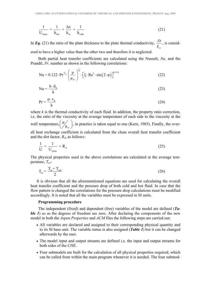
Figure 1 shows a commercial compact heat exchanger comprising of adjacent corru-gated plates, while the details of the plate are shown in Figure 2. Each plate has herring-bone type corrugations and two adjacent plates are superposed so that the opposite corruga-tions form a cross-type pattern with the crests of the corrugations nearly in contact. The corrugation type and angle affects the heat exchanger performance (i.e. the heat transfer rate and the pressure drop) (Shah & Wanniarachchi, 1991).
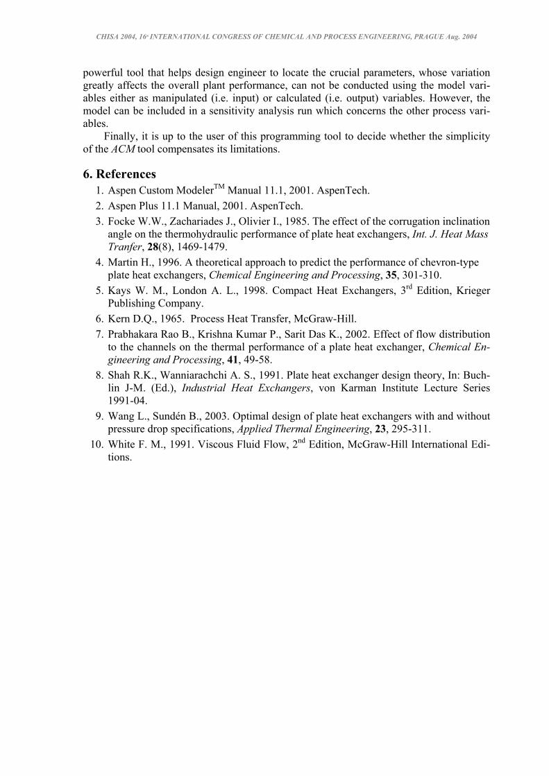
In addition, there is a number of possible flow arrangements (Figure 3) depending on the required heat transfer duty, available pressure drop, minimum and maximum allowable velocities and the flow rate ratio of the two fluid streams. Shah & Wanniarachchi (1991) classify them as series, looped and complex:
• The series flow arrangement (Figure 3a) is used for small flow rates and very close temperature approaches. Each flow passage corresponds to a pass. Thus the N pass-N pass arrangement consists of (2N-1) thermal plates. A pass in a CHE refers to a sub-section of the exchanger (a group of channels) in which the whole fluid stream on one side flows one full length of the plate.
• Looped patterns are the most frequently used and are suitable for large flow rates, but relative small temperature differences on each fluid side. There are two types of looped patterns the U- (Figure 1 & 3b) and the Z- (Figure 3c) arrangement.
• The complex flow arrangement (Figure 3d) results by combining Z-arrangements in series, with generally identical number of thermal plates in each pass and are pre-ferred when there is a significant difference in the flow rates of the two fluid streams and in the corresponding available pressure drops.
In the present work, the Aspen Custom Modeler (ACM) is applied, in order to intro-duce in the commercial simulator Aspen Plus® the module of a herringbone type plate heat exchanger. A typical CHE with looped flow arrangement was chosen as case study because this type is the most widely used. The design equations are identical for both U-and Z-type arrangement. However, if a series or a complex flow arrangement is to be studied the pro-grammer must modify the correlations for the pressure drop prediction. The novel equip-ment modelled in ACM is used within Aspen Plus®.
CHISA 2004, 16th INTERNATIONAL CONGRESS OF CHEMICAL AND PROCESS ENGINEERING, PRAGUE Aug. 2004
Figure 1. A typical plate heat exchanger (by Alfa Laval) Figure 2. View of a corrugated plate
(a)
(b)
(c)
(d)
Figure 3. Basic flow patterns in a CHE: (a) Series arrangement or N pass-N pass with individual passes per channel, (b) Looped arrangement of U-type, (c) Looped arrangement of Z-type, (d) Complex arrangement (Shah & Wanniarachchi, 1991).
Lp
w

CHISA 2004, 16th INTERNATIONAL CONGRESS OF CHEMICAL AND PROCESS ENGINEERING, PRAGUE Aug. 2004
Design Equations The model used in this study is the one proposed by Martin (1996) that predicts the
friction factor and the heat transfer coefficient of a herringbone type CHE as a function of the corrugation inclination angle and the fluid Reynolds number. This model, which is based on a purely theoretical equation (i.e. a generalized Lévêque equation) as well as on experimental data, has been used by various investigators (e.g. Wang & Sundén, 2003). Moreover, Prabhakara Rao et al. (2002) consider this model the best available, although its predictions have ±20% uncertainty.
The model calculates the overall heat-transfer coefficient and the friction factor of a CHE as a function of its geometric characteristics (e.g. corrugation angle) and the fluid Reynolds number. The characteristic length used in the calculations is the hydraulic diame-ter, dh, which is defined as:
h
ˆ4 ad ⋅=
Φ (1)
The area enlargement factor, Φ, is the ratio of the developed surface area to the projected area and is defined as:
( )2
21 xx 1 + 1 + x + 4 1 + 6 2
⎛ ⎞Φ ≈ ⋅ ⋅⎜ ⎟⎜ ⎟
⎝ ⎠ (2)
where x is a dimensionless parameter defined as: ˆ2 π ax =
Λ⋅ ⋅ (3)
and depends on the ratio of amplitude â to the wavelength Λ. The geometric characteristics of a plate are shown in Figure 4.
Figure 4. Geometric characteristics of a herringbone type plate.
The friction factor, ξ, is calculated by the equation:
( )
( ) ( ) ( )( )
( )( )ο 1
cos φ 1 - cos φ1 = + ξ ξ Re ξ Re
b tan φ + c sin φ + cos φ
⋅ ⋅
(4)
ˆ2a
Λ
φ

CHISA 2004, 16th INTERNATIONAL CONGRESS OF CHEMICAL AND PROCESS ENGINEERING, PRAGUE Aug. 2004
Thus, the friction factor apart from the Reynolds number depends on the corrugation angle, φ. The friction factors at angle 0o with the corrugations of the two plates shifted by π, so that the crests of the corrugations to be in contact, ξο, and at angle 90o, ξ1, are involved in the equation and are given by:
oο
Bξ = , Re < 2000Re
(5)
( )-2οξ = 1.81 g Re - 1.5 , Re 2000⋅ ⋅ ≥ (6)
( )1 1oξ = a Re , a 1⋅ξ ≥ (7)
The parameters a, b and c are predicted by fitting a curve to experimental data and are set to the values of 3.8, 0.18, 0.36 respectively, whereas the constant Bo can be predicted from Figure 5 (White, 1991). Furthermore, the friction factor at angle 90o and phase 0 (i.e. no contact points between the two plates), ξ1o, is calculated by:
11o 1
B= + C , Re < 2000Re
ξ (8)
11o n
Kξ = , Re 2000Re
≥ (9)
The constants B1, C1 and K1 depend on the area enlargement factor according to the equa-tions:
1e1 2
BB = Φ
(10)
1e1
CC = Φ
(11)
1e1 1 + n
KK = Φ
(12)
The values of the constants B1e, C1e, K1e and n have been extracted from the experimental results of Focke et al. (1985) and have the following values: B1e=1280, C1e=5.63, K1e=63.8 and n=0.289.
The Reynolds number, Re, is calculated using the superficial velocity, u, the viscosity, µ, and the density, ρ, of the fluid according to Eqs. (13), (14), (15).
hρ u dRe = µ
⋅ ⋅ (13)
flow
Qu = A
(14)
flow channelsˆA = 2 a w n⋅ ⋅ ⋅ (15)
where Q is the total volumetric flow of each fluid of the CHE, Aflow is the average flow cross-section and nchannels is the number of channels in which the flow is distributed.
The overall pressure drop, ∆P, for each fluid of the compact heat exchanger is given by: 2 2
p3h
ξ Re L µ∆P =
2 d ρ⋅ ⋅ ⋅
⋅ ⋅ (16)

CHISA 2004, 16th INTERNATIONAL CONGRESS OF CHEMICAL AND PROCESS ENGINEERING, PRAGUE Aug. 2004
The dimensions of the plate (w, Lp) are defined in Figure 2. It is considered that each fluid makes one pass inside the CHE and therefore the number
of plates required for the heat exchange is calculated using Eqs. (17) to (20).
reqplates
p
An =
w L Φ⋅ ⋅ (17)
p in outQ = m c Τ -T⋅ ⋅ (18)
req lnQ A U= ⋅ ⋅∆Τ (19)
( ) ( )( ) ( )
in out out in
in out out in
hot cold hot coldln
hot cold hot cold
T - T - T - T∆Τ = LMTD =
ln T - T - ln T - T (20)
where the required area for heat transfer, Areq, is calculated from the fraction of the total heat exchanged, Q, to the overall heat transfer coefficient, U, and to the mean logarithmic temperature difference, ∆Τln. Also, the total heat transferred is proportional to the mass flow rate of the fluid, m , the specific heat capacity, cp, and the input, Tin, and output, Tout, temperature of one of the fluids used in the CHE. It should be mentioned that for opera-tional reasons a CHE must be comprised of an odd number of plates, so as the CHE to in-clude an equal number channels for the hot and the cold fluid.
Figure 5. Values of constant Bo vs duct cross section (White, 1991).
In addition to the pressure drop, the overall clean heat transfer coefficient, Uc, is calcu-lated using the cold and hot side partial heat transfer coefficients, hcold and hhot:
o4 B⋅
ˆ2 aw⋅
CHISA 2004, 16th INTERNATIONAL CONGRESS OF CHEMICAL AND PROCESS ENGINEERING, PRAGUE Aug. 2004
clean hot ss cold
1 1 ∆x 1 = + + U h k h
(21)
In Eq. (21) the ratio of the plate thickness to the plate thermal conductivity, ss
∆xk
, is consid-
ered to have a higher value than the other two and therefore it is neglected.
Both partial heat transfer coefficients are calculated using the Nusselt, Nu, and the Prandtl, Pr, number as shown in the following correlations:
( )1
61
30.3742
w
µNu = 0.122 Pr Re sin 2 φµ
⎛ ⎞⎡ ⎤⋅ ⋅ ⋅ ξ ⋅ ⋅ ⋅⎜ ⎟ ⎣ ⎦
⎝ ⎠ (22)
hh dNu = k⋅ (23)
pcPr =
kµ⋅
(24)
where k is the thermal conductivity of each fluid. In addition, the property ratio correction, i.e. the ratio of the viscosity at the average temperature of each side to the viscosity at the
wall temperature,w
µµ
⎛ ⎞⎜ ⎟⎝ ⎠
, in practice is taken equal to one (Kern, 1965). Finally, the over-
all heat exchange coefficient is calculated from the clean overall heat transfer coefficient and the dirt factor, Rd, as follows:
dclean
1 1 = + RU U
(25)
The physical properties used in the above correlations are calculated at the average tem-perature, Tav:
in outav
T + TT = 2
(26)
It is obvious that all the aforementioned equations are used for calculating the overall heat transfer coefficient and the pressure drop of both cold and hot fluid. In case that the flow pattern is changed the correlations for the pressure drop calculations must be modified accordingly. It is noted that all the variables must be expressed in SI units.
Programming procedure The independent (fixed) and dependent (free) variables of the model are defined (Ta-
ble 1) so as the degrees of freedom are zero. After declaring the components of the new model in both the Aspen Properties and ACM files the following steps are carried out:
• All variables are declared and assigned to their corresponding physical quantity and to its SI base unit. The variable status is also assigned (Table 1) but it can be changed afterwards by the user.
• The model input and output streams are defined i.e. the input and output streams for both sides of the CHE.
• Four submodels are built for the calculation of all physical properties required, which can be called from within the main program whenever it is needed. The four submod-

CHISA 2004, 16th INTERNATIONAL CONGRESS OF CHEMICAL AND PROCESS ENGINEERING, PRAGUE Aug. 2004
els correspond to the cold and hot fluid and the two possible fluid conditions (i.e. gas or liquid).
• The design equations of the CHE (Eqs.1-26), as well as the mass and energy balances, are written using ACM format.
• The model is compiled with ACM compiler and run in steady state mode.
• The input and output ports are assigned to the input and output streams. The ports used are the default SI-ports provided by ACM. The model is run again in steady state mode.
• Finally, it is compiled using the C++ compiler and the resulting dll file is exported to the same folder with Aspen Properties file.
In order to use the new model in an Aspen Plus® simulation the module must be introduced from the Library (in the References menu) and it appears in the Model Library bar. From this point the new module can be manipulated from within the simulator environment.
Table 1. Variables of a CHE
Variables
Physical properties cp, k, kss, µ, µw, ρ
Fixed (input) variables a, a , b, B1e, c, C1e, K1e, Lp, m , n, Q , Rd, Tcoldin, Thotin, w, ∆Thot, ∆x, Λ, φ
Free (calculated) variables Aflow, Areq, Β1, C1, dh, hhot, hcold, K1, nchannels, nplates, Nu, Pr, Q, Re, Tav, u, Uclean, U, x, ∆p, ∆Τcold, ∆Τln, ξ, ξ1, ξο, ξ1ο, Φ
The modelled CHE was introduced in Aspen Plus® and was validated using the data of Martin (1996). Furthermore, the new equipment was integrated with conventional process equipment and it was found to function very well.
4. Conclusions With the intention of reducing cost and time for plant design and optimization, process
simulation has become a vital tool. However, the equipment library offered by commercial process simulators is usually limited to conventional equipment and must be enhanced by new equipment, the performance of which need to be studied in conjunction with conven-tional ones.
ACM is a modelling language provided by Aspen Plus® that is intended for users with minimum programming skills. The user is allowed to introduce all the required model equations in the form that they are available in the literature, i.e. without having to bring them in a y=f(x) form. Additionally, the equations can be arranged regardless of the order that they are going to be solved. The new model can be easily incorporated in the process simulator and has full access to the build-in routines for the physical properties estimation. Moreover, the input and output variables can be easily interchanged (i.e. without altering the computer code) from within the main simulation.
However, there are several drawbacks in using an exported ACM model. For example, the components, the parameters and the physical property method used in the novel equip-ment can be altered only within ACM environment. Additionally, the component names must be explicitly declared and identical names must be used in the ACM model, in the As-pen Properties file and in the Aspen Plus® simulation run. Sensitivity analysis, which is a
CHISA 2004, 16th INTERNATIONAL CONGRESS OF CHEMICAL AND PROCESS ENGINEERING, PRAGUE Aug. 2004
powerful tool that helps design engineer to locate the crucial parameters, whose variation greatly affects the overall plant performance, can not be conducted using the model vari-ables either as manipulated (i.e. input) or calculated (i.e. output) variables. However, the model can be included in a sensitivity analysis run which concerns the other process vari-ables.
Finally, it is up to the user of this programming tool to decide whether the simplicity of the ACM tool compensates its limitations.
6. References 1. Aspen Custom ModelerTM Manual 11.1, 2001. AspenTech. 2. Aspen Plus 11.1 Manual, 2001. AspenTech. 3. Focke W.W., Zachariades J., Olivier I., 1985. The effect of the corrugation inclination
angle on the thermohydraulic performance of plate heat exchangers, Int. J. Heat Mass Tranfer, 28(8), 1469-1479.
4. Martin H., 1996. A theoretical approach to predict the performance of chevron-type plate heat exchangers, Chemical Engineering and Processing, 35, 301-310.
5. Kays W. M., London A. L., 1998. Compact Heat Exchangers, 3rd Edition, Krieger Publishing Company.
6. Kern D.Q., 1965. Process Heat Transfer, McGraw-Hill. 7. Prabhakara Rao B., Krishna Kumar P., Sarit Das K., 2002. Effect of flow distribution
to the channels on the thermal performance of a plate heat exchanger, Chemical En-gineering and Processing, 41, 49-58.
8. Shah R.K., Wanniarachchi A. S., 1991. Plate heat exchanger design theory, In: Buch-lin J-M. (Ed.), Industrial Heat Exchangers, von Karman Institute Lecture Series 1991-04.
9. Wang L., Sundén B., 2003. Optimal design of plate heat exchangers with and without pressure drop specifications, Applied Thermal Engineering, 23, 295-311.
10. White F. M., 1991. Viscous Fluid Flow, 2nd Edition, McGraw-Hill International Edi-tions.