calibration screen development
DESCRIPTION
Calibration Screen Development. Claire Cramer Brian Stalder Gautham Narayan Christopher Stubbs Department of Physics Harvard University. Keith Lykke Steve Brown Allan Smith NIST John Tonry Jeff Morgan Ken Chambers PanSTARRS. Overview. Objectives Status Challenges Plans. - PowerPoint PPT PresentationTRANSCRIPT

1
Calibration Screen Development Calibration Screen Development Calibration Screen Development Calibration Screen Development
Claire CramerClaire Cramer
Brian StalderBrian Stalder
Gautham NarayanGautham Narayan
Christopher StubbsChristopher Stubbs
Department of Physics Department of Physics
Harvard UniversityHarvard University
Claire CramerClaire Cramer
Brian StalderBrian Stalder
Gautham NarayanGautham Narayan
Christopher StubbsChristopher Stubbs
Department of Physics Department of Physics
Harvard UniversityHarvard University
Keith LykkeKeith Lykke
Steve BrownSteve Brown
Allan SmithAllan Smith
NISTNIST
John TonryJohn Tonry
Jeff MorganJeff Morgan
Ken ChambersKen Chambers
PanSTARRSPanSTARRS
Keith LykkeKeith Lykke
Steve BrownSteve Brown
Allan SmithAllan Smith
NISTNIST
John TonryJohn Tonry
Jeff MorganJeff Morgan
Ken ChambersKen Chambers
PanSTARRSPanSTARRS

2
OverviewOverviewOverviewOverview
• ObjectivesObjectives
• StatusStatus
• ChallengesChallenges
• PlansPlans
• ObjectivesObjectives
• StatusStatus
• ChallengesChallenges
• PlansPlans

3
ObjectivesObjectivesObjectivesObjectives
• We hope to achieve unprecedented We hope to achieve unprecedented precisionprecision in LSST in LSST
photometry.photometry.
• This requires knowingThis requires knowing• Relative sensitivity of apparatus vs. wavelength
• Transmission of atmosphere.
• Our plan is to use a NIST-calibrated photodiode as the Our plan is to use a NIST-calibrated photodiode as the
primary flux sensitivity reference. primary flux sensitivity reference.
• We will use full-aperture illumination of the system to map out We will use full-aperture illumination of the system to map out
each pixel’s response vs. wavelength, for each LSST filter. each pixel’s response vs. wavelength, for each LSST filter.
• (Measurement of atmospheric transmission is a distinct issue, (Measurement of atmospheric transmission is a distinct issue,
for a later conversation)for a later conversation)

4
Detectors are better characterized Detectors are better characterized than than anyany celestial source! celestial source!
Detectors are better characterized Detectors are better characterized than than anyany celestial source! celestial source!
nm
QE
Spectrum of Vega NIST photodiode QE Spectrum of Vega NIST photodiode QE

5
Basic ConceptBasic Concept
Back-illuminated diffuserBack-illuminated diffuser
Monitoring photodiodeMonitoring photodiode
LSST apertureLSST aperture
focal planefocal plane
Basic ConceptBasic Concept
Back-illuminated diffuserBack-illuminated diffuser
Monitoring photodiodeMonitoring photodiode
LSST apertureLSST aperture
focal planefocal plane
6
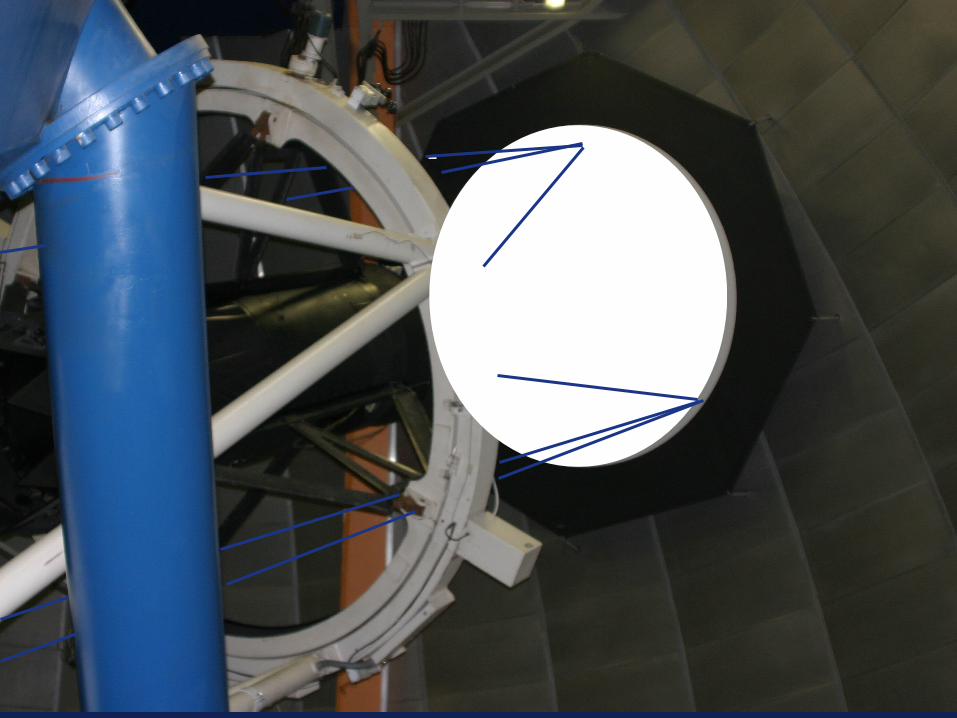
Demonstration of the concept at CTIODemonstration of the concept at CTIODemonstration of the concept at CTIODemonstration of the concept at CTIO
• Measured full system transmission Measured full system transmission using a tunable laser and NIST using a tunable laser and NIST diode. diode.
• This was not a permanent This was not a permanent installation. installation.
• Measured full system transmission Measured full system transmission using a tunable laser and NIST using a tunable laser and NIST diode. diode.
• This was not a permanent This was not a permanent installation. installation.

7
Tunable laser (400 nm - 2 microns) Tunable laser (400 nm - 2 microns)
from Opotekfrom Opotek Tunable laser (400 nm - 2 microns) Tunable laser (400 nm - 2 microns)
from Opotekfrom Opotek
Second harmonic Second harmonic (532 nm) generator(532 nm) generator
Mixer (to 355 nm) Mixer (to 355 nm)
1.064 micron 1.064 micron NdYAG pulsed NdYAG pulsed
pump laserpump laser
Tunable Tunable downconverterdownconverter
Second harmonic Second harmonic (532 nm) generator(532 nm) generator
Mixer (to 355 nm) Mixer (to 355 nm)
1.064 micron 1.064 micron NdYAG pulsed NdYAG pulsed
pump laserpump laser
Tunable Tunable downconverterdownconverter
8

9
A/D converter module
Photdiode preamp
USB extender
Integrator electronics
Calibrated photodiode
Beam launch optics
Optical Fiber
10
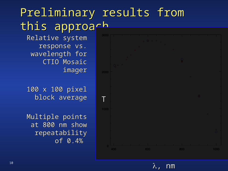
Preliminary results from this Preliminary results from this approachapproachPreliminary results from this Preliminary results from this approachapproach
Relative system Relative system response vs. response vs.
wavelength for wavelength for CTIO Mosaic CTIO Mosaic
imagerimager
100 x 100 pixel 100 x 100 pixel block averageblock average
Multiple points at Multiple points at 800 nm show 800 nm show
repeatability of repeatability of 0.4% 0.4%
Relative system Relative system response vs. response vs.
wavelength for wavelength for CTIO Mosaic CTIO Mosaic
imagerimager
100 x 100 pixel 100 x 100 pixel block averageblock average
Multiple points at Multiple points at 800 nm show 800 nm show
repeatability of repeatability of 0.4% 0.4%
, nm, nm
TT

11
Actual data from CTIO R Band Actual data from CTIO R Band Colored Glass FilterColored Glass Filter
Actual data from CTIO R Band Actual data from CTIO R Band Colored Glass FilterColored Glass Filter
System throughput System throughput Filtered/blank=filter onlyFiltered/blank=filter only
System throughput System throughput Filtered/blank=filter onlyFiltered/blank=filter only
, nm, nm , nm, nm

12
950 nm950 nm950 nm950 nm

13
960 nm960 nm960 nm960 nm

14
970 nm970 nm970 nm970 nm
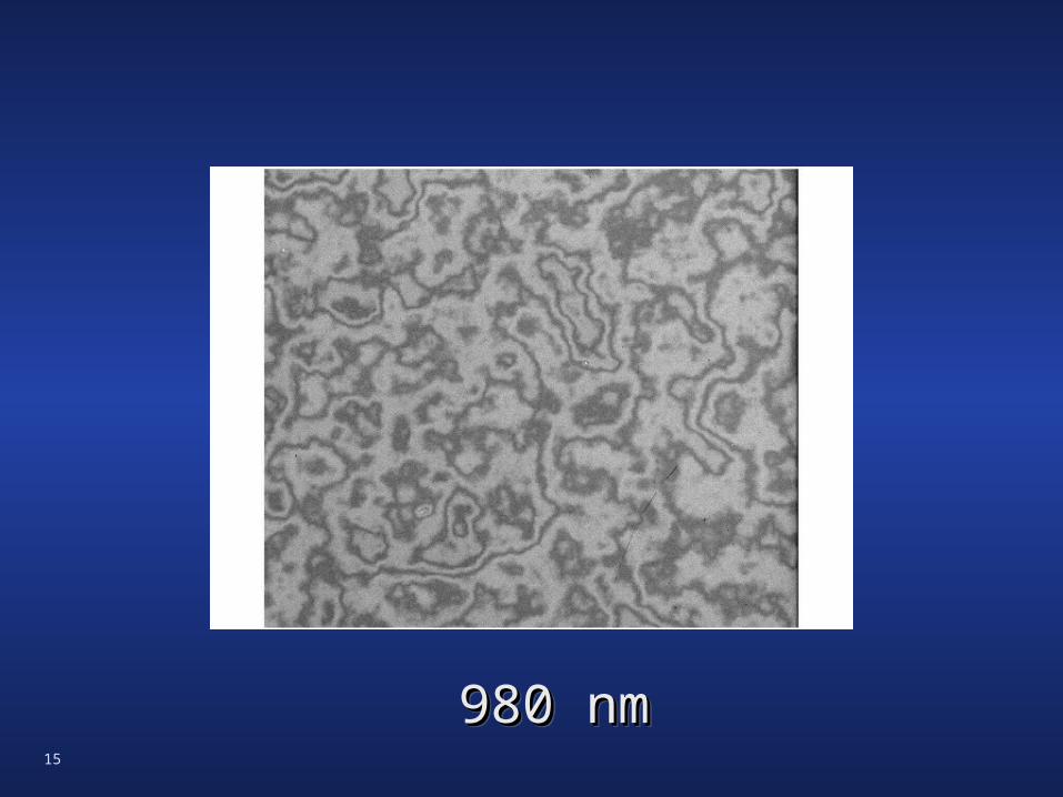
15
980 nm980 nm980 nm980 nm

16
990 nm990 nm990 nm990 nm

17
1000 nm1000 nm1000 nm1000 nm

18
1010 nm1010 nm1010 nm1010 nm
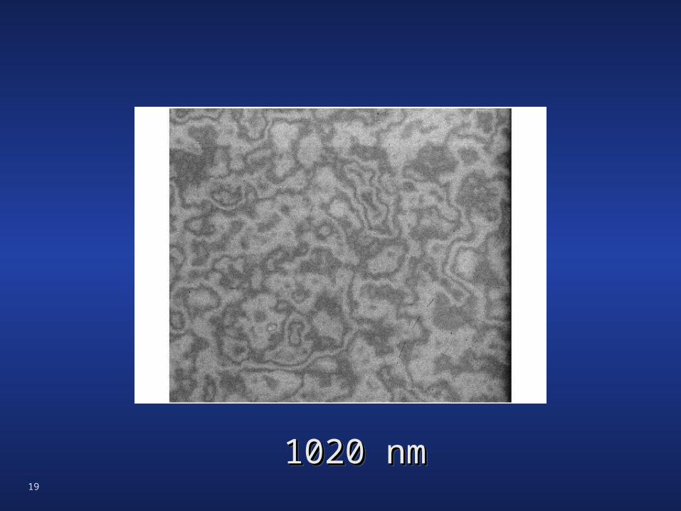
19
1020 nm1020 nm1020 nm1020 nm
20
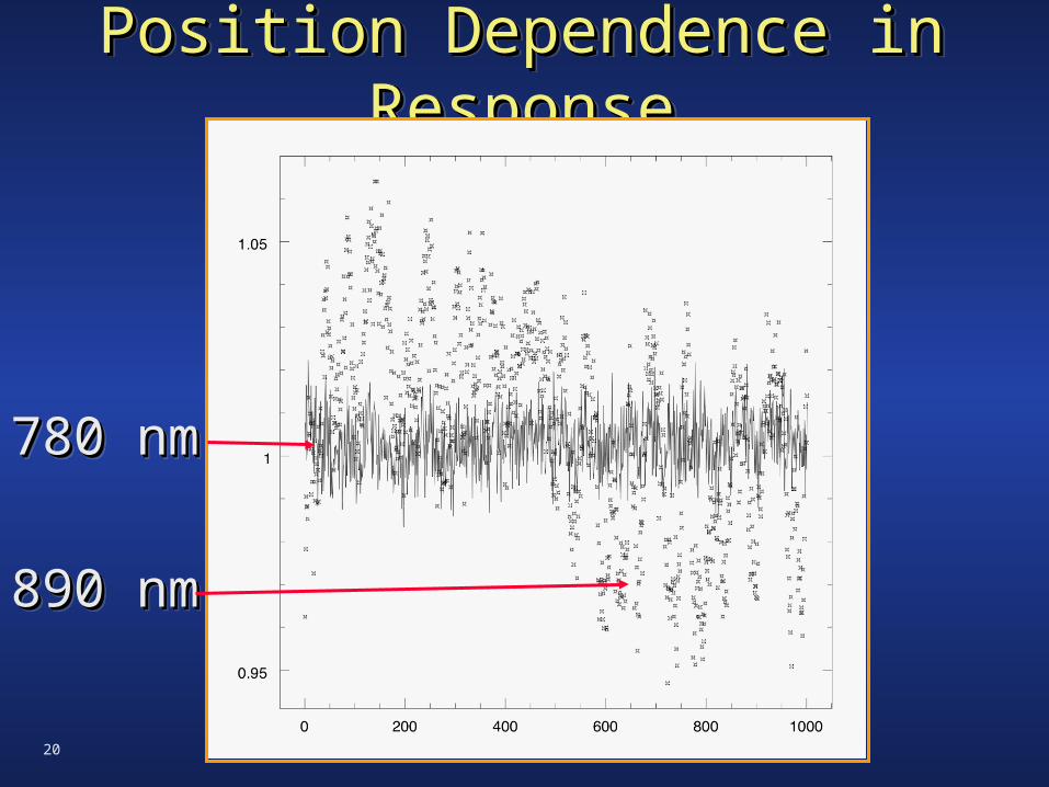
Position Dependence in ResponsePosition Dependence in ResponsePosition Dependence in ResponsePosition Dependence in Response
780 nm780 nm
890 nm890 nm
780 nm780 nm
890 nm890 nm

21
This approach requiresThis approach requiresThis approach requiresThis approach requires
1.1. Photodiode monitor & circuitPhotodiode monitor & circuit
2.2. Tunable light source with adequate intensityTunable light source with adequate intensity
3.3. Uniform radiance screen, to ~10%. An adjustable Uniform radiance screen, to ~10%. An adjustable
source of illumination across the screen would be source of illumination across the screen would be
nice!nice!
4.4. Calibration pipeline that exploits these data.Calibration pipeline that exploits these data.
5.5. Dark dome (or at least uniform illumination) Dark dome (or at least uniform illumination)
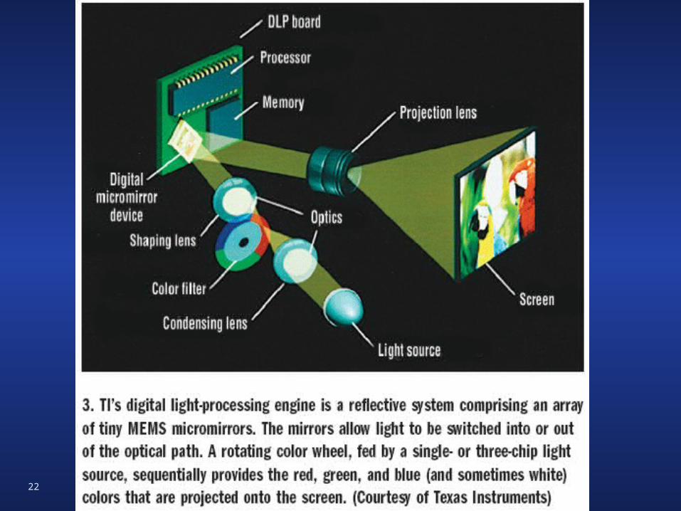
22

23
We are building a DLP-driven We are building a DLP-driven flatfield screenflatfield screen
We are building a DLP-driven We are building a DLP-driven flatfield screenflatfield screen
Hacked DLP digital projector, optical fiberHacked DLP digital projector, optical fiber
Transmissive screenTransmissive screen
Diverging mirrorsDiverging mirrors
Tunable sourceTunable source
We can currently generate a 2m dia spot in ~26 inches depthWe can currently generate a 2m dia spot in ~26 inches depthI expect we can fill LSST screen uniformly with 2m depth I expect we can fill LSST screen uniformly with 2m depth

24
Transferring uniform radianceTransferring uniform radianceTransferring uniform radianceTransferring uniform radiance
Flat, by def. Non-uniform Iteratively flattenedFlat, by def. Non-uniform Iteratively flattened
reciprocalreciprocal

25
ChallengesChallengesChallengesChallenges
• We can add a collimator, to restrict angles of We can add a collimator, to restrict angles of
emission to the FOV of camera, but then uniformity emission to the FOV of camera, but then uniformity
measurement is difficult. measurement is difficult.
• Need optimized optical surfaces for reflectors to Need optimized optical surfaces for reflectors to
project decent spot in minimal standoff distance. project decent spot in minimal standoff distance.
• Tunable light sources below 400nm are difficult.Tunable light sources below 400nm are difficult.
• Don’t yet know requisite cadence of filter Don’t yet know requisite cadence of filter
transmission measurements. transmission measurements.
• Plan to ship v1.0 to PanSTARRS in May.Plan to ship v1.0 to PanSTARRS in May.

26
Selected ReferencesSelected ReferencesSelected ReferencesSelected References
• Stubbs & Tonry “Stubbs & Tonry “Toward 1% Photometry: End-to-End Toward 1% Photometry: End-to-End Calibration of Astronomical Telescopes and Detectors” Calibration of Astronomical Telescopes and Detectors” ApJ 646, 1436 (2006)
• Stubbs et al. “Stubbs et al. “Preliminary Results from Detector-Based Preliminary Results from Detector-Based Throughput Calibration of the CTIO Mosaic Imager and Blanco Throughput Calibration of the CTIO Mosaic Imager and Blanco Telescope Using a Tunable Laser”Telescope Using a Tunable Laser” astro-ph/0609260 (2006) astro-ph/0609260 (2006)
• Stubbs et al, “Stubbs et al, “Toward More Precise Survey Photometry for Toward More Precise Survey Photometry for PanSTARRS and LSST: Measuring Directly the Optical PanSTARRS and LSST: Measuring Directly the Optical Transmission Spectrum of the Atmosphere” Transmission Spectrum of the Atmosphere” PASP 119, 1163 PASP 119, 1163 (2007)(2007)
• Technical Memo on Screen Design Considerations. C. Stubbs Technical Memo on Screen Design Considerations. C. Stubbs Dev 2007. Dev 2007.