ccaattaalloogg - sama sistemi s.r.l · pdf filesama sistemi s.r.l. has iso 9001 – 2000...
TRANSCRIPT
Via Atteone, 75 - 00133 Roma - Tel / Fax +39 06 2003860 - e-mail : [email protected] http : www.samasistemisrl.com
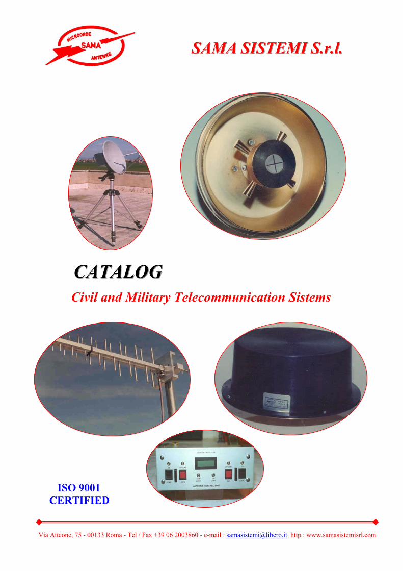
ISO 9001 CERTIFIED
CCCAAATTTAAALLLOOOGGG
Civil and Military Telecommunication Sistems
SSSAAAMMMAAA SSSIIISSSTTTEEEMMMIII SSS...rrr...lll...

Via Atteone, 75 - 00133 Roma - Tel / Fax +39 06 2003860 - e-mail : [email protected] http : www.samasistemisrl.com
SAMA SISTEMI S.r.l. was founded by a team of specialist in antennas field. The activity planned by the company is the design, develop and manufacturing
of antennas for fixed, mobile communication and also special antennas according to customers requirements ( Telemetry – Field measurement – High temperature Operation – missile application – High security – Ultra broad-band antennas High efficiency and size reduced antennas – Conformal antennas – etc….. )
Our antennas are realized according to highest standard for civil use, or to
MIL specs for military application.
SAMA SISTEMI S.r.l. has ISO 9001 – 2000 qualification
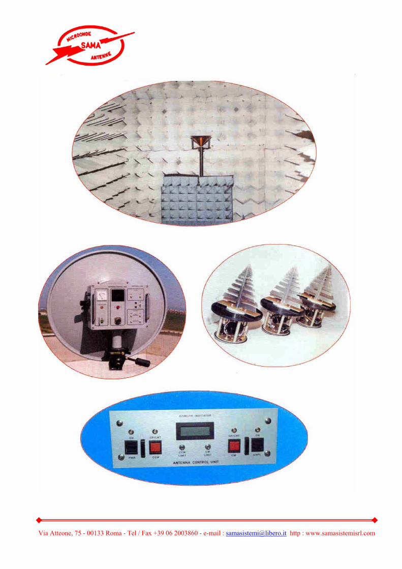
SAMA SISTEMI S.r.l. has capability in design and manufactor for several types of antennas from HF to EHF ( 50 GHz ) and an Anechoic Chamber
“ CTR type “ for radiation pattern measurements and recording.
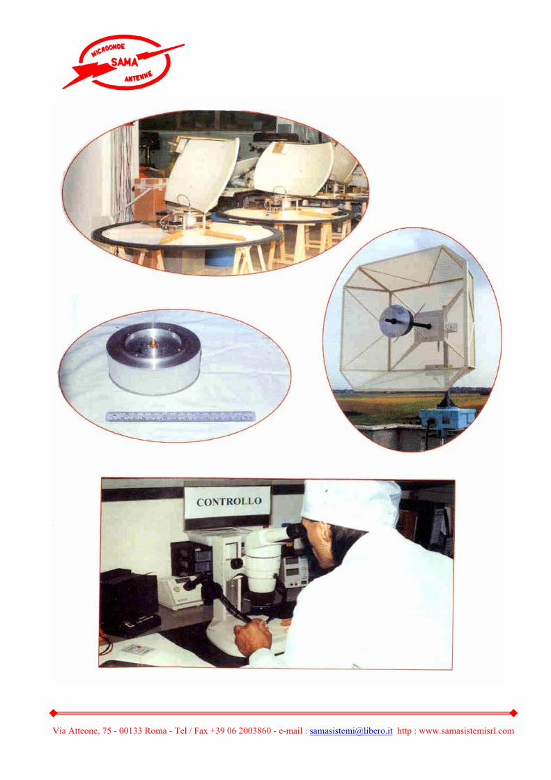
SAMA SISTEMI S.r.l. has in house all the facilities necessary to the production of all the device in this catalog.
Trough extensive use of quality control drawings and with the application of
quality incoming inspection procedures can ensure that all purchased raw materials are of the required type.
For programs requiring high reliability and extreme care, such as in satellite
and missile application SAMA SISTEMI S.r.l. has fully implemented the necessary technical combination of hardware and software capabilities well suited to produce
“ HI-REL “ components.
- INTRODUCTION -
Via Atteone, 75 - 00133 Roma - Tel / Fax +39 06 2003860 - e-mail : [email protected] http : www.samasistemisrl.com
1. Single Yagi Antenna
2. Crossed – Yagi Antenna
3. Ground Plane Antenna
4. Vertical Collinear Antenna
5. Short Back – Fire Antenna
6. Helical Antenna 7. Yagi for Cellular
8. Log – Periodic Antenna
9. Planar / Patch Antenna
10. Biconical Antenna
11. Rod Antenna
12. Omni Directional Antenna
13. Low Profile Antenna
14. Aerodynamic Blade
15. Electric Field Antenna
16. Tunable Dipole Antenna 17. Small Loop Antenna
18. Our product 19. / 20. Reflector 21./ 22. Feed for Reflector
23. / 24. Horn Antenna
25. / 26. Power Dividers / Combiners
27. Wave – Guide to Coaxial Adapter
28. 90° Hybrid 3dB
29. Automatic Leveling Control
30. Modulator Circuit Assembly
31. / 32. Receiving Antenna System for 1÷26 GHz 1.
33. / 34. Automatic Tracking Telemetry Antenna System
INDEX
Via Atteone, 75 - 00133 Roma - Tel / Fax +39 06 2003860 - e-mail : [email protected] http : www.samasistemisrl.com
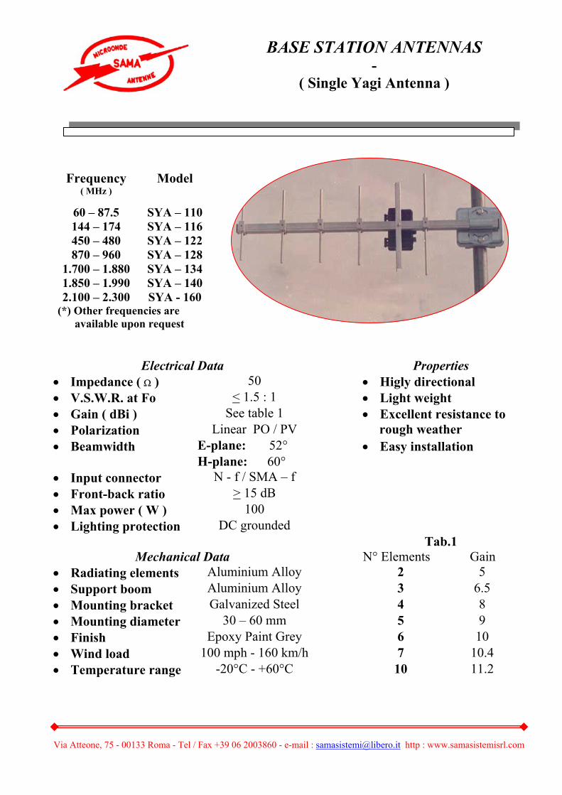
Electrical Data Properties • Impedance ( Ω ) 50 • Higly directional • V.S.W.R. at Fo < 1.5 : 1 • Light weight • Gain ( dBi ) See table 1 • Excellent resistance to • Polarization Linear PO / PV rough weather • Beamwidth E-plane: 52° • Easy installation H-plane: 60° • Input connector N - f / SMA – f • Front-back ratio > 15 dB • Max power ( W ) 100 • Lighting protection DC grounded Tab.1
Mechanical Data N° Elements Gain • Radiating elements Aluminium Alloy 2 5 • Support boom Aluminium Alloy 3 6.5 • Mounting bracket Galvanized Steel 4 8 • Mounting diameter 30 – 60 mm 5 9 • Finish Epoxy Paint Grey 6 10 • Wind load 100 mph - 160 km/h 7 10.4 • Temperature range -20°C - +60°C 10 11.2
Frequency ( MHz )
Model
60 – 87.5 SYA – 110 144 – 174 SYA – 116 450 – 480 SYA – 122 870 – 960 SYA – 128
1.700 – 1.880 SYA – 134 1.850 – 1.990 SYA – 140 2.100 – 2.300 SYA - 160
(*) Other frequencies are available upon request
BASE STATION ANTENNAS -
( Single Yagi Antenna )
Via Atteone, 75 - 00133 Roma - Tel / Fax +39 06 2003860 - e-mail : [email protected] http : www.samasistemisrl.com
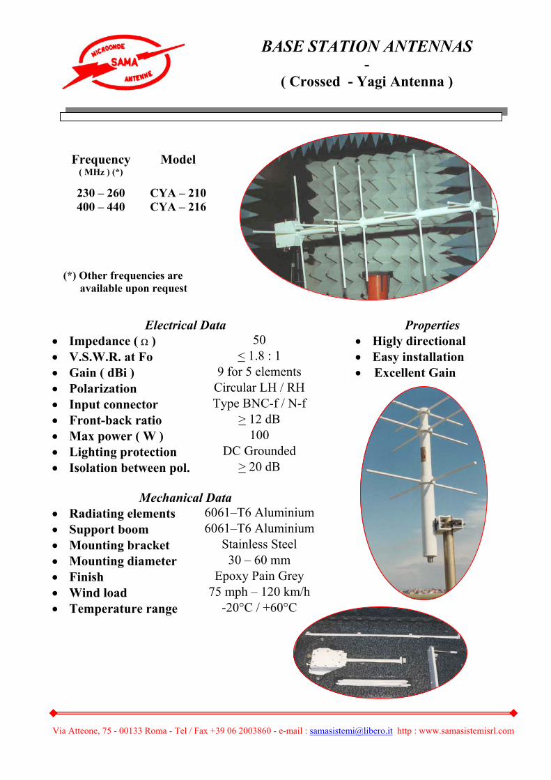
Electrical Data Properties • Impedance ( Ω ) 50 • Higly directional • V.S.W.R. at Fo < 1.8 : 1 • Easy installation • Gain ( dBi ) 9 for 5 elements • Excellent Gain • Polarization Circular LH / RH • Input connector Type BNC-f / N-f • Front-back ratio > 12 dB • Max power ( W ) 100 • Lighting protection DC Grounded • Isolation between pol. > 20 dB
Mechanical Data • Radiating elements 6061–T6 Aluminium • Support boom 6061–T6 Aluminium • Mounting bracket Stainless Steel • Mounting diameter 30 – 60 mm • Finish Epoxy Pain Grey • Wind load 75 mph – 120 km/h • Temperature range -20°C / +60°C
Frequency ( MHz ) (*)
Model
230 – 260 CYA – 210 400 – 440 CYA – 216
(*) Other frequencies are available upon request
BASE STATION ANTENNAS -
( Crossed - Yagi Antenna )
Via Atteone, 75 - 00133 Roma - Tel / Fax +39 06 2003860 - e-mail : [email protected] http : www.samasistemisrl.com
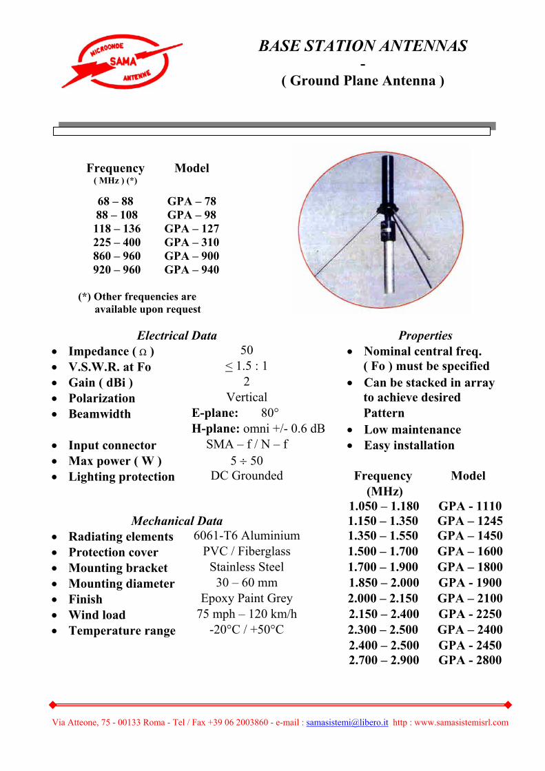
Electrical Data Properties • Impedance ( Ω ) 50 • Nominal central freq. • V.S.W.R. at Fo < 1.5 : 1 ( Fo ) must be specified • Gain ( dBi ) 2 • Can be stacked in array • Polarization Vertical to achieve desired • Beamwidth E-plane: 80° Pattern H-plane: omni +/- 0.6 dB • Low maintenance • Input connector SMA – f / N – f • Easy installation • Max power ( W ) 5 ÷ 50 • Lighting protection DC Grounded Frequency Model (MHz) 1.050 – 1.180 GPA - 1110
Mechanical Data 1.150 – 1.350 GPA – 1245• Radiating elements 6061-T6 Aluminium 1.350 – 1.550 GPA – 1450• Protection cover PVC / Fiberglass 1.500 – 1.700 GPA – 1600• Mounting bracket Stainless Steel 1.700 – 1.900 GPA – 1800• Mounting diameter 30 – 60 mm 1.850 – 2.000 GPA - 1900• Finish Epoxy Paint Grey 2.000 – 2.150 GPA – 2100• Wind load 75 mph – 120 km/h 2.150 – 2.400 GPA - 2250• Temperature range -20°C / +50°C 2.300 – 2.500 GPA – 2400 2.400 – 2.500 GPA - 2450 2.700 – 2.900 GPA - 2800
BASE STATION ANTENNAS -
( Ground Plane Antenna )
Frequency ( MHz ) (*)
Model
68 – 88 GPA – 78 88 – 108 GPA – 98 118 – 136 GPA – 127 225 – 400 GPA – 310 860 – 960 GPA – 900 920 – 960 GPA – 940
(*) Other frequencies are available upon request

Via Atteone, 75 - 00133 Roma - Tel / Fax +39 06 2003860 - e-mail : [email protected] http : www.samasistemisrl.com
Electrical Data Properties • Impedance ( Ω ) 50 • Extremely broad band • V.S.W.R. at Fo < 1.6 : 1 • Omnidirectional coverage • Gain ( dBi ) 2 - 8 • Rugged construction • Polarization Vertical • Easy installation • Beamwidth E-plane: 40° at +/- 3dB • No ground plane H-plane: omni +/-0.6 dB • Input connector N – f / SMA – f • Max power ( W ) 100 • Lighting protection DC Grounded
Mechanical Data • Radiating elements 6061-T6 Aluminium • Support boom 6061-T6 Aluminium • Radome PVC / Fiberglass • Mounting bracket Stainless Steel • Mounting diameter 30 – 50 mm • Finish Epoxy Paint Grey • Wind load 75 mph – 120 km/h • Temperature range -30°C / +70°C
Frequency ( MHz ) (*)
Model
118 – 136 VCA - 410 100 – 156 VCA - 425 225 – 400 VCA - 440 430 – 440 VCA – 435 860 – 940 VCA - 900 920 – 960 VCA - 940
2.100 - 2.300 VCA – 2200 2.300 – 2.500 VCA - 2400 2.500 – 2.700 VCA - 2600
(*) Other frequencies are available upon request
BASE STATION ANTENNAS -
( Vertical Collinear Antenna )

Via Atteone, 75 - 00133 Roma - Tel / Fax +39 06 2003860 - e-mail : [email protected] http : www.samasistemisrl.com
Electrical Data Properties • Impedance ( Ω ) 50 • High directivity • V.S.W.R. at Fo < 1.6 : 1 • Highly efficient radiator• Gain ( dBi ) 8 – 12 • Sturdy and light • Polarization Linear / Circular construction • Input connector SMA - f / N – f • Easy installation • Front-back ratio > 20 dB • Max power ( W ) 100
Mechanical Data • Radiating elements Brass • Mounting bracket Stainless Steel • Mounting diameter 30 – 50 mm • Finish Epoxy Paint Grey • Wind load 75 mph / 120 km/h • Temperature range -20°C / +60°C • Net weight 1 Kg typical
Frequency ( MHz ) (*)
Model
460 – 860 SBF - 510 1.000 – 2.000 SBF – 515 1.500 - 3.000 SBF – 520 2.000 – 4.000 SBF – 530
(*) Other frequencies are
available upon request
BASE STATION ANTENNAS -
( Short Back – Fire Antenna )
Via Atteone, 75 - 00133 Roma - Tel / Fax +39 06 2003860 - e-mail : [email protected] http : www.samasistemisrl.com
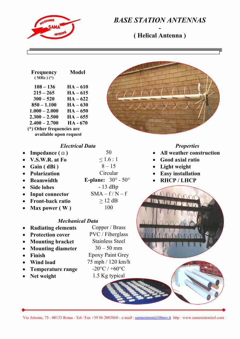
Electrical Data Properties • Impedance ( Ω ) 50 • All weather construction • V.S.W.R. at Fo < 1.6 : 1 • Good axial ratio • Gain ( dBi ) 8 – 15 • Light weight • Polarization Circular • Easy installation • Beamwidth E-plane: 30° - 50° • RHCP / LHCP • Side lobes - 13 dBp • Input connector SMA – f / N – f • Front-back ratio > 12 dB • Max power ( W ) 100
Mechanical Data • Radiating elements Copper / Brass • Protection cover PVC / Fiberglass • Mounting bracket Stainless Steel • Mounting diameter 30 – 50 mm • Finish Epoxy Paint Grey • Wind load 75 mph / 120 km/h • Temperature range -20°C / +60°C • Net weight 1.5 Kg typical
Frequency ( MHz ) (*)
Model
108 – 136 HA – 610 215 – 265 HA – 615 300 – 520 HA – 622
850 – 1.100 HA – 630 1.000 – 2.000 HA – 650 2.300 – 2.500 HA – 655 2.400 – 2.700 HA - 670
(*) Other frequencies are available upon request
BASE STATION ANTENNAS -
( Helical Antenna )
Via Atteone, 75 - 00133 Roma - Tel / Fax +39 06 2003860 - e-mail : [email protected] http : www.samasistemisrl.com
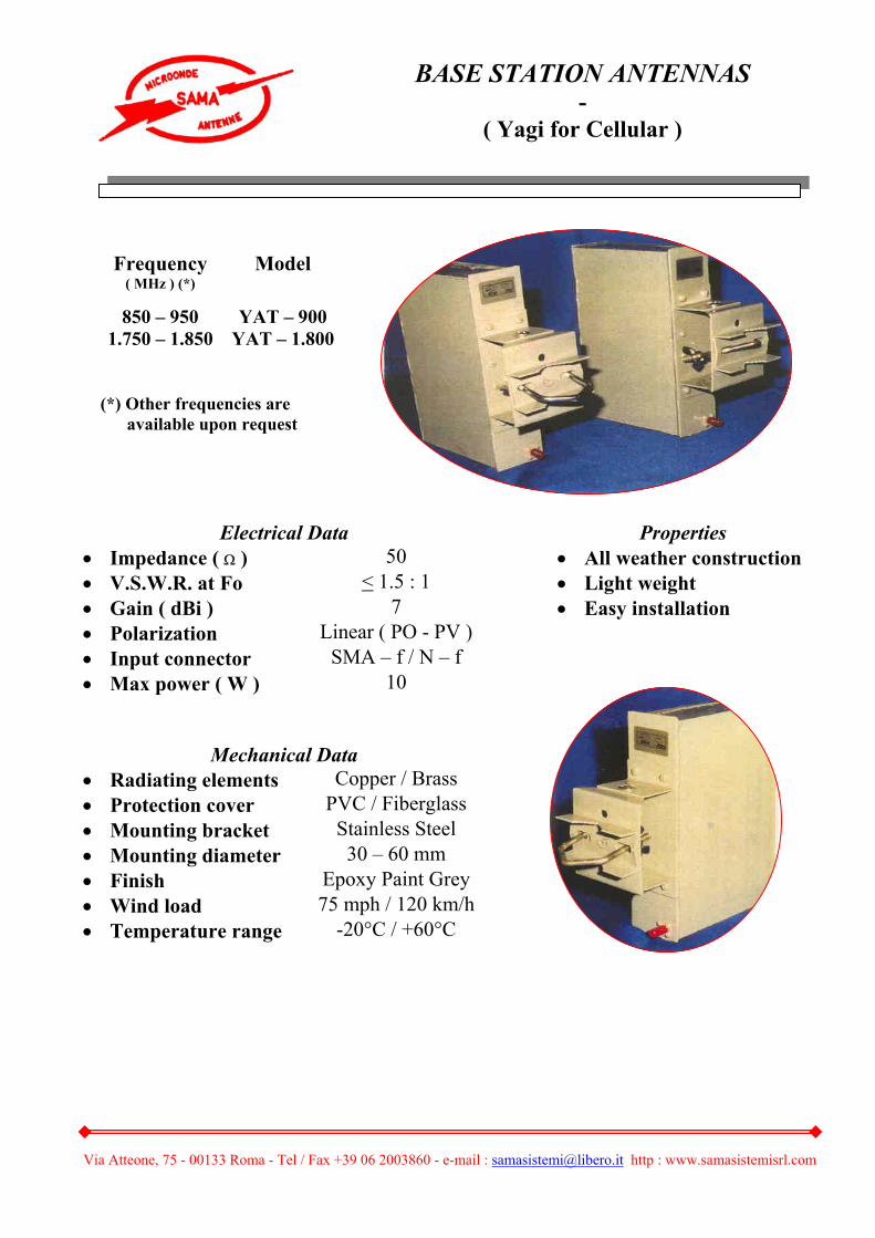
Electrical Data Properties • Impedance ( Ω ) 50 • All weather construction • V.S.W.R. at Fo < 1.5 : 1 • Light weight • Gain ( dBi ) 7 • Easy installation • Polarization Linear ( PO - PV ) • Input connector SMA – f / N – f • Max power ( W ) 10
Mechanical Data • Radiating elements Copper / Brass • Protection cover PVC / Fiberglass • Mounting bracket Stainless Steel • Mounting diameter 30 – 60 mm • Finish Epoxy Paint Grey • Wind load 75 mph / 120 km/h • Temperature range -20°C / +60°C
Frequency ( MHz ) (*)
Model
850 – 950 YAT – 900 1.750 – 1.850 YAT – 1.800
(*) Other frequencies are available upon request
BASE STATION ANTENNAS -
( Yagi for Cellular )
Via Atteone, 75 - 00133 Roma - Tel / Fax +39 06 2003860 - e-mail : [email protected] http : www.samasistemisrl.com
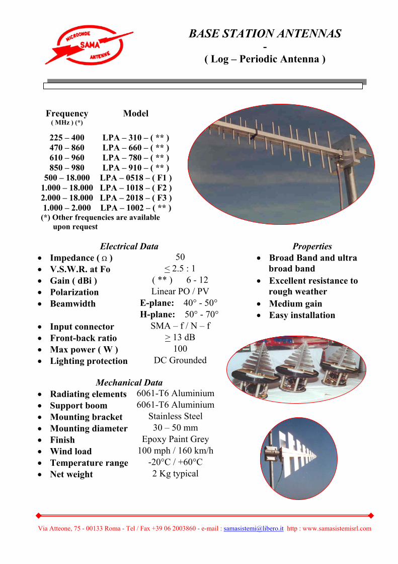
Electrical Data Properties • Impedance ( Ω ) 50 • Broad Band and ultra • V.S.W.R. at Fo < 2.5 : 1 broad band • Gain ( dBi ) ( ** ) 6 - 12 • Excellent resistance to • Polarization Linear PO / PV rough weather • Beamwidth E-plane: 40° - 50° • Medium gain H-plane: 50° - 70° • Easy installation • Input connector SMA – f / N – f • Front-back ratio > 13 dB • Max power ( W ) 100 • Lighting protection DC Grounded
Mechanical Data • Radiating elements 6061-T6 Aluminium• Support boom 6061-T6 Aluminium• Mounting bracket Stainless Steel • Mounting diameter 30 – 50 mm • Finish Epoxy Paint Grey • Wind load 100 mph / 160 km/h • Temperature range -20°C / +60°C • Net weight 2 Kg typical
Frequency ( MHz ) (*)
Model
225 – 400 LPA – 310 – ( ** ) 470 – 860 LPA – 660 – ( ** ) 610 – 960 LPA – 780 – ( ** ) 850 – 980 LPA – 910 – ( ** )
500 – 18.000 LPA – 0518 – ( F1 )1.000 – 18.000 LPA – 1018 – ( F2 )2.000 – 18.000 LPA – 2018 – ( F3 )1.000 – 2.000 LPA – 1002 – ( ** )
(*) Other frequencies are available upon request
BASE STATION ANTENNAS -
( Log – Periodic Antenna )

Via Atteone, 75 - 00133 Roma - Tel / Fax +39 06 2003860 - e-mail : [email protected] http : www.samasistemisrl.com
Electrical Data Properties • Impedance ( Ω ) 50 • Low profile • V.S.W.R. at Fo < 1.5 : 1 • Suitable for cellular • Gain ( dBi ) 7 applications • Polarization Linear / Circular • Easy installation • Beamwidth E-plane: 50° • Linear or circular H-plane: 80° polarizations • Input connector SMA – f • Front-back ratio > 13 dB • Max power ( W ) 50
Frequency ( MHz ) ( * )
Model
1.850 – 2.000 PTA – 1925 - 7 2.000 – 2.150 PTA – 2075 - 7
Mechanical Data 2.150 – 2.400 PTA – 2275 - 7• Radiating elements Brass 2.300 – 2.500 PTA – 2400 - 7• Protection cover PVC 2.400 – 2.500 PTA – 2450 - 7• Mounting bracket Stainless Steel 2.700 – 2.900 PTA – 2800 - 7• Finish Epoxy Paint Grey • Temperature range -20°C / + 60°C
(*) Other frequencies are available upon request
• Net weight 0.3 Kg typical
Frequency ( MHz ) (*)
Model
824 – 896 PTA – 860 - 7 870 – 960 PTA – 915 - 7
1.050 – 1.180 PTA – 1115 - 7 1.150 – 1.350 PTA – 1250 - 7 1.350 – 1.550 PTA – 1450 - 7 1.500 – 1.700 PTA – 1600 - 7 1.700 – 1.900 PTA – 1800 - 7
BASE STATION ANTENNAS -
( Planar / Patch Antenna )
Via Atteone, 75 - 00133 Roma - Tel / Fax +39 06 2003860 - e-mail : [email protected] http : www.samasistemisrl.com
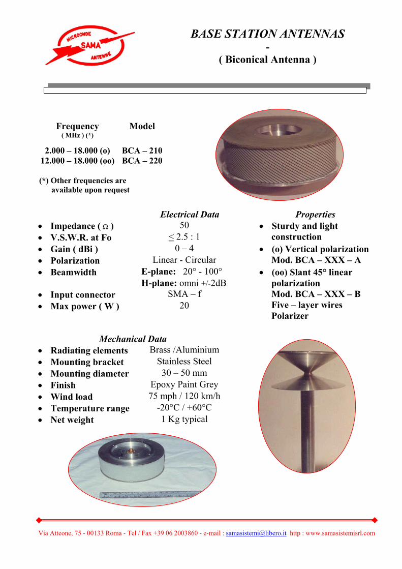
Electrical Data Properties • Impedance ( Ω ) 50 • V.S.W.R. at Fo < 2.5 : 1
• Sturdy and light construction
• Gain ( dBi ) 0 – 4 • Polarization Linear - Circular
• (o) Vertical polarization Mod. BCA – XXX – A
• Beamwidth E-plane: 20° - 100° H-plane: omni +/-2dB • Input connector SMA – f • Max power ( W ) 20
• (oo) Slant 45° linear polarization Mod. BCA – XXX – B Five – layer wires Polarizer
Mechanical Data
• Radiating elements Brass /Aluminium • Mounting bracket Stainless Steel • Mounting diameter 30 – 50 mm • Finish Epoxy Paint Grey • Wind load 75 mph / 120 km/h • Temperature range -20°C / +60°C • Net weight 1 Kg typical
Frequency ( MHz ) (*)
Model
2.000 – 18.000 (o) BCA – 210 12.000 – 18.000 (oo) BCA – 220
(*) Other frequencies are available upon request
BASE STATION ANTENNAS -
( Biconical Antenna )
Via Atteone, 75 - 00133 Roma - Tel / Fax +39 06 2003860 - e-mail : [email protected] http : www.samasistemisrl.com
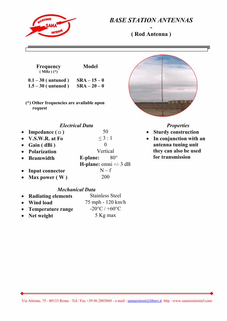
Electrical Data Properties • Impedance ( Ω ) 50 • Sturdy construction • V.S.W.R. at Fo < 3 : 1 • Gain ( dBi ) 0 • Polarization Vertical • Beamwidth E-plane: 80° H-plane: omni +/- 3 dB
• In conjunction with an antenna tuning unit they can also be used for transmission
• Input connector N – f • Max power ( W ) 200
Mechanical Data • Radiating elements Stainless Steel • Wind load 75 mph - 120 km/h • Temperature range -20°C / +60°C • Net weight 5 Kg max
Frequency ( MHz ) (*)
Model
0.1 – 30 ( untuned ) SRA – 15 – 0 1.5 – 30 ( untuned ) SRA – 20 – 0
(*) Other frequencies are available upon request
BASE STATION ANTENNAS-
( Rod Antenna )
Via Atteone, 75 - 00133 Roma - Tel / Fax +39 06 2003860 - e-mail : [email protected] http : www.samasistemisrl.com
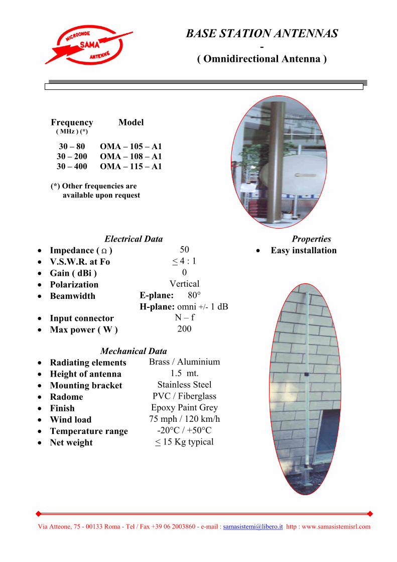
Electrical Data Properties • Impedance ( Ω ) 50 • Easy installation • V.S.W.R. at Fo < 4 : 1 • Gain ( dBi ) 0 • Polarization Vertical • Beamwidth E-plane: 80° H-plane: omni +/- 1 dB• Input connector N – f • Max power ( W ) 200
Mechanical Data • Radiating elements Brass / Aluminium • Height of antenna 1.5 mt. • Mounting bracket Stainless Steel • Radome PVC / Fiberglass • Finish Epoxy Paint Grey • Wind load 75 mph / 120 km/h • Temperature range -20°C / +50°C • Net weight < 15 Kg typical
Frequency ( MHz ) (*)
Model
30 – 80 OMA – 105 – A1 30 – 200 OMA – 108 – A1 30 – 400 OMA – 115 – A1
(*) Other frequencies are available upon request
BASE STATION ANTENNAS -
( Omnidirectional Antenna )
Via Atteone, 75 - 00133 Roma - Tel / Fax +39 06 2003860 - e-mail : [email protected] http : www.samasistemisrl.com
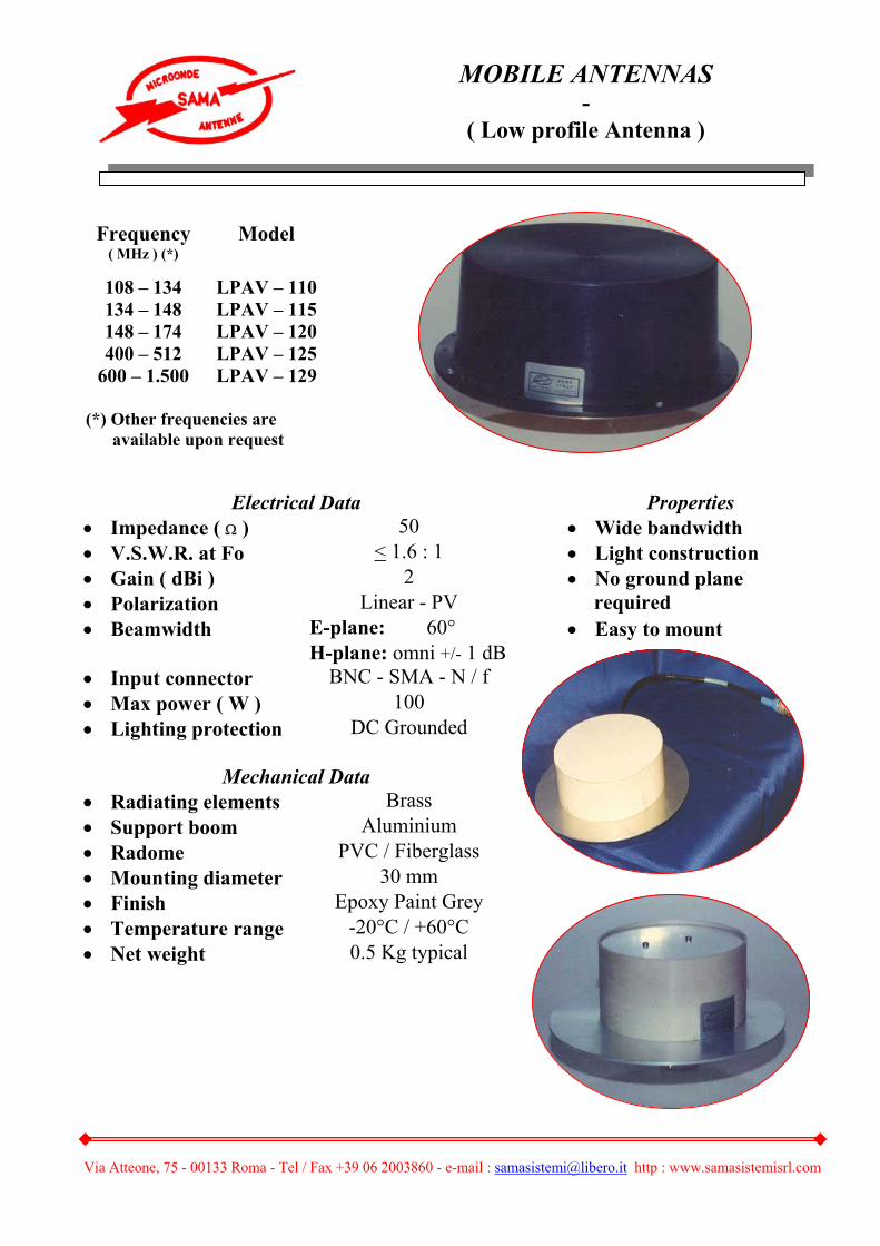
Electrical Data Properties
• Impedance ( Ω ) 50 • Wide bandwidth • V.S.W.R. at Fo < 1.6 : 1 • Light construction • Gain ( dBi ) 2 • Polarization Linear - PV
• No ground plane required
• Beamwidth E-plane: 60° • Easy to mount H-plane: omni +/- 1 dB• Input connector BNC - SMA - N / f • Max power ( W ) 100 • Lighting protection DC Grounded
Mechanical Data • Radiating elements Brass • Support boom Aluminium • Radome PVC / Fiberglass • Mounting diameter 30 mm • Finish Epoxy Paint Grey • Temperature range -20°C / +60°C • Net weight 0.5 Kg typical
Frequency ( MHz ) (*)
Model
108 – 134 LPAV – 110 134 – 148 LPAV – 115 148 – 174 LPAV – 120 400 – 512 LPAV – 125
600 – 1.500 LPAV – 129
(*) Other frequencies are available upon request
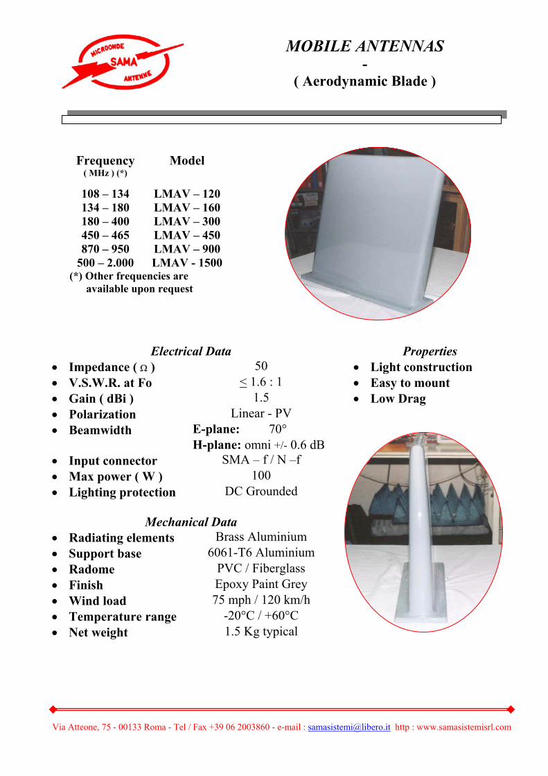
MOBILE ANTENNAS -
( Low profile Antenna )
Via Atteone, 75 - 00133 Roma - Tel / Fax +39 06 2003860 - e-mail : [email protected] http : www.samasistemisrl.com
• Gain ( dBi ) 1.5 • Low Drag • Polarization Linear - PV • Beamwidth E-plane: 70° H-plane: omni +/- 0.6 dB • Input connector SMA – f / N –f • Max power ( W ) 100 • Lighting protection DC Grounded
Mechanical Data • Radiating elements Brass Aluminium • Support base 6061-T6 Aluminium • Radome PVC / Fiberglass • Finish Epoxy Paint Grey • Wind load 75 mph / 120 km/h • Temperature range -20°C / +60°C • Net weight 1.5 Kg typical
Electrical Data Properties • Impedance ( Ω ) 50 • Light construction • V.S.W.R. at Fo < 1.6 : 1 • Easy to mount
Frequency ( MHz ) (*)
Model
108 – 134 LMAV – 120 134 – 180 LMAV – 160 180 – 400 LMAV – 300 450 – 465 LMAV – 450 870 – 950 LMAV – 900
500 – 2.000 LMAV - 1500 (*) Other frequencies are available upon request
MOBILE ANTENNAS -
( Aerodynamic Blade )

Via Atteone, 75 - 00133 Roma - Tel / Fax +39 06 2003860 - e-mail : [email protected] http : www.samasistemisrl.com
DESCRIPTION
• This antenna is well suited for all RF monitoring applications
( EMC – EMI – RF spectrum surveillance – Field strenght measurements ) connecting output to a power meter or to an oscilloscope.
A wood tripod support is suggested for field measurement.
Particular design of internal amplifier – buffer offer a flat response over the entire frequency band.
The unit is delivered with instruction manual and calibration curve to convert the output level into the incoming field strenght.
SPECIFICATIONS
• Frequency range 10 KHz – 200 MHz• Zo 50 ohm • Antenna Whip • Connector Type “N” – female• Supply voltage 9 + 9 Volt
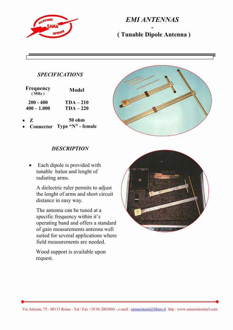
EMI ANTENNAS-
( Electric Field Antenna )
Via Atteone, 75 - 00133 Roma - Tel / Fax +39 06 2003860 - e-mail : [email protected] http : www.samasistemisrl.com
DESCRIPTION
• Each dipole is provided with
tunable balun and lenght of radiating arms.
A dielectric ruler permits to adjust the lenght of arms and short circuit distance in easy way.
The antenna can be tuned at a specific frequency within it’s operating band and offers a standard of gain measurements antenna well suited for several applications where field measurements are needed.
Wood support is available upon request.
SPECIFICATIONS
Frequency ( MHz )
Model
200 - 400 TDA – 210 400 – 1.000 TDA – 220
• Z 50 ohm • Connector Type “N” - female
EMI ANTENNAS -
( Tunable Dipole Antenna )

Via Atteone, 75 - 00133 Roma - Tel / Fax +39 06 2003860 - e-mail : [email protected] http : www.samasistemisrl.com
DESCRIPTION
• This kind of antenna is particularly suitable for EMI measurements and for all applications where magnetic field sensor is required.
SPECIFICATIONS
Frequency ( MHz )
Model
0.015 - 30 SLA – 100
• 15” diameter loop • Low frequency applications • Magnetic field sensitive
EMI ANTENNAS -
( Small Loop Antenna )
Via Atteone, 75 - 00133 Roma - Tel / Fax +39 06 2003860 - e-mail : [email protected] http : www.samasistemisrl.com
Via Atteone, 75 - 00133 Roma - Tel / Fax +39 06 2003860 - e-mail : [email protected] http : www.samasistemisrl.com
DESCRIPTION
• Frequency range Upon request ( from “L” band to “KA” band ) • Gain > 25 dB ( upon customer’s request ) • Sidelobes Better than 25 dB / peak • Polarization Linear ( PO / PV ) – Circular ( upon request ) • Special design Ultra low sidelobes configurations are available upon request
for relay link applications
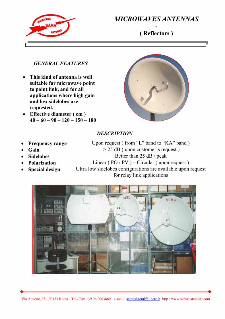
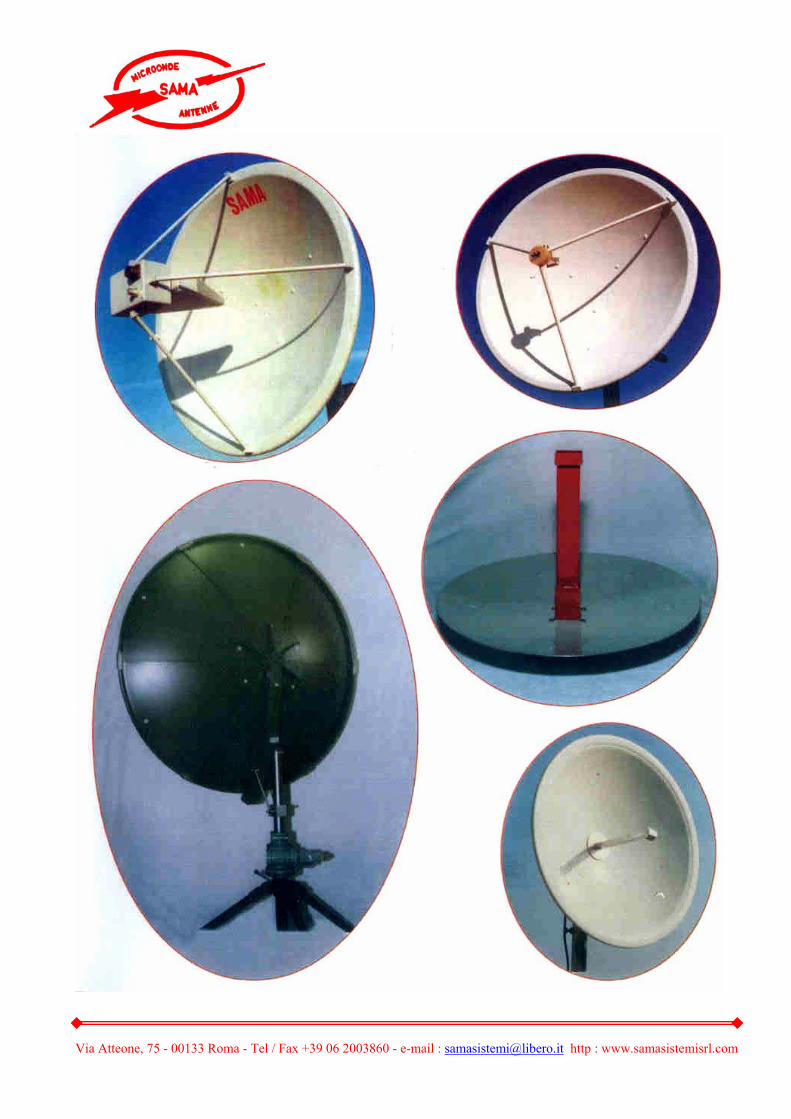
GENERAL FEATURES
• This kind of antenna is well suitable for microwave point to point link, and for all applications where high gain and low sidelobes are requested.
• Effective diameter ( cm ) 40 – 60 – 90 – 120 – 150 – 180
MICROWAVES ANTENNAS -
( Reflectors )
Via Atteone, 75 - 00133 Roma - Tel / Fax +39 06 2003860 - e-mail : [email protected] http : www.samasistemisrl.com
Via Atteone, 75 - 00133 Roma - Tel / Fax +39 06 2003860 - e-mail : [email protected] http : www.samasistemisrl.com
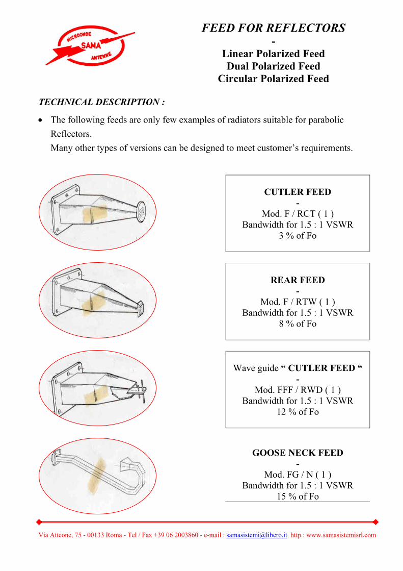
TECHNICAL DESCRIPTION :
• The following feeds are only few examples of radiators suitable for parabolic
Reflectors.
Many other types of versions can be designed to meet customer’s requirements.
CUTLER FEED -
Mod. F / RCT ( 1 ) Bandwidth for 1.5 : 1 VSWR
3 % of Fo
REAR FEED -
Mod. F / RTW ( 1 ) Bandwidth for 1.5 : 1 VSWR
8 % of Fo
Wave guide “ CUTLER FEED “ -
Mod. FFF / RWD ( 1 ) Bandwidth for 1.5 : 1 VSWR
12 % of Fo
GOOSE NECK FEED -
Mod. FG / N ( 1 ) Bandwidth for 1.5 : 1 VSWR
15 % of Fo
FEED FOR REFLECTORS -
Linear Polarized Feed Dual Polarized Feed
Circular Polarized Feed

Via Atteone, 75 - 00133 Roma - Tel / Fax +39 06 2003860 - e-mail : [email protected] http : www.samasistemisrl.com
Coax “ DIPOLE FEED “
- Mod. F / RDP ( 1 )
Bandwidth for 1.5 : 1 VSWR 12 % of Fo
RING FOCUS -
Mod. F / FR ( 1 ) Bandwidth for 1.5 : 1 VSWR
8 % of Fo
ANULAR FEED -
Mod. F / AF ( 1 ) Bandwidth for 1.5 : 1 VSWR
7 % of Fo
LOG FEED -
Mod. F / LP – Fl / Fh ( 1 ) Extraordinary wide band
For 2.5 : 1 VSWR 0,5 – 18 GHz
SHORT BACK - FIRE FEED -
Mod. FF / SDB – Fl / Fh ( 1 ) Bandwidth for 2 : 1 VSWR one octave - Fmax : 4 GHz

Via Atteone, 75 - 00133 Roma - Tel / Fax +39 06 2003860 - e-mail : [email protected] http : www.samasistemisrl.com
GENERTAL DESCRIPTION
• Rectangular Horn Antennas are Typically linearly polarized with different beam widths and “ H “ planes.
The flare angle in each plane and resulting aperture dimension are designed to meet specified beam width, sidelobes and gain values.
Flange Type
Model
Frequency ( GHz )
Wave Guide( WR )
Type ( RG )
UG
• HRA – L – (*) 1.12 – 1.70 650 103 / U 418 A / U Rect B/U • HRA – R – (*) 1.70 – 2.60 430 105 / U 437 A / U Rect B/U • HRA – S – (*) 2.60 – 3.95 284 75 / U 584 A / U RD • HRA – H – (*) 3.95 – 5.85 187 95 / U 407 A / U RD • HRA – C – (*) 5.85 – 8.20 137 106 / U 441 A / U RD • HRA – X – (*) 8.15 – 12.4 90 67 / U 135 A / U SQ • HRA – KU – (*) 12.4 – 18.0 75 349 / U 419 A / U SQ • HRA – K – (*) 18 – 26.5 42 53 / U 595 A / U SQ • HRA – KA – (*) 26.5 – 40 28 96 / U 599 A / U SQ • HRA – 20 – (*) 7.5 – 18 D 750 D 20 FLG 750
GENERAL FEATURES
• Wide range of beamwidths • Low VSWR • Linearly polarized • Standard waveguide band • Light – weight aluminium • SMA – N connector available • (*) 10 – 15 – 20 dB Gain
MICROWAVES ANTENNAS -
( Horn Antenna )

Via Atteone, 75 - 00133 Roma - Tel / Fax +39 06 2003860 - e-mail : [email protected] http : www.samasistemisrl.com
Via Atteone, 75 - 00133 Roma - Tel / Fax +39 06 2003860 - e-mail : [email protected] http : www.samasistemisrl.com
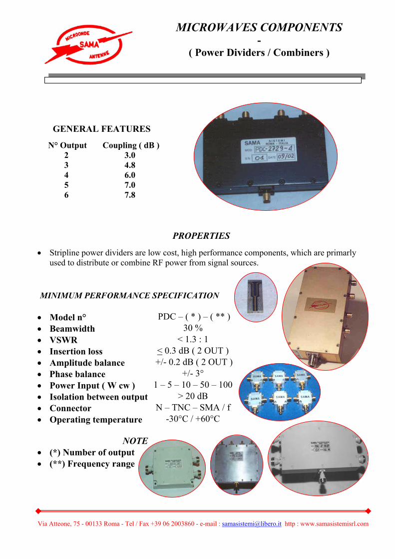
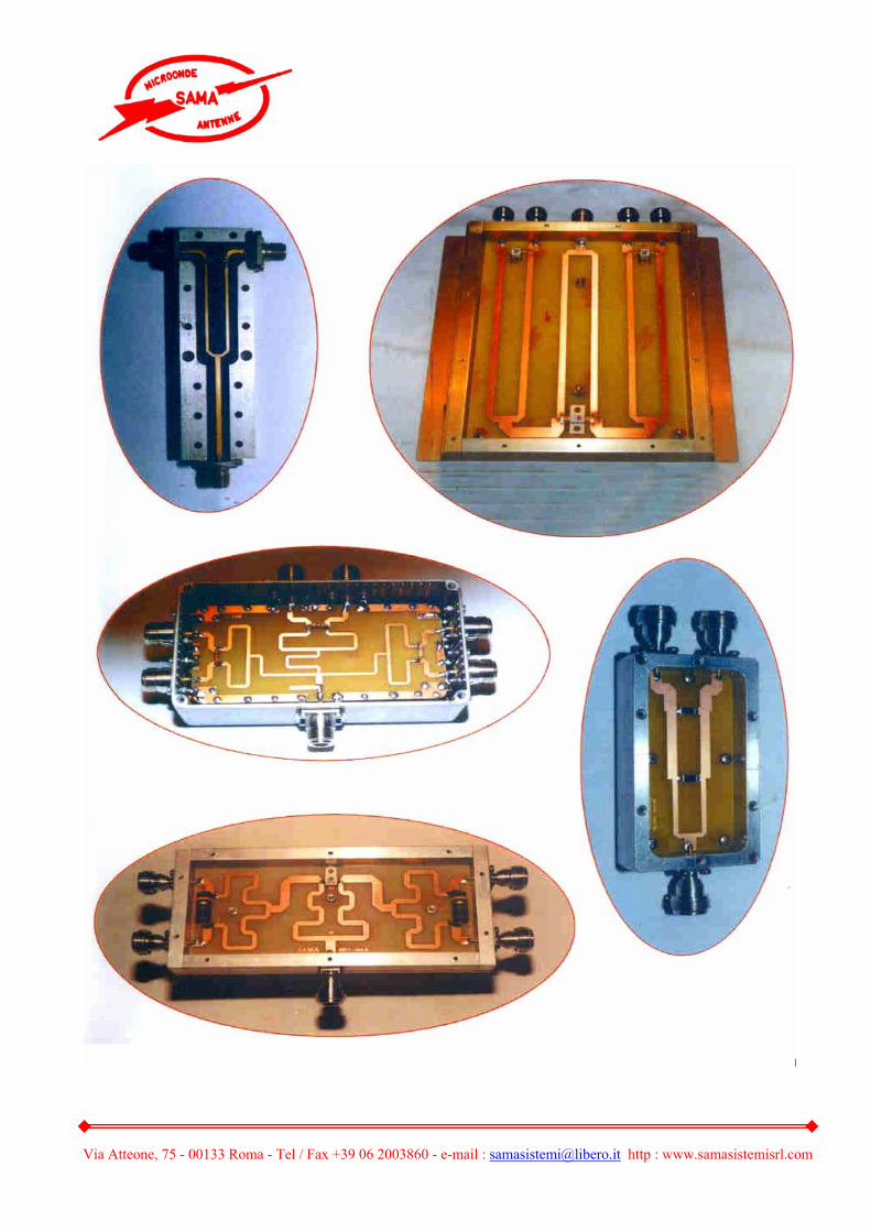
PROPERTIES
• Stripline power dividers are low cost, high performance components, which are primarly used to distribute or combine RF power from signal sources.
MINIMUM PERFORMANCE SPECIFICATION • Model n° PDC – ( * ) – ( ** ) • Beamwidth 30 % • VSWR < 1.3 : 1 • Insertion loss < 0.3 dB ( 2 OUT ) • Amplitude balance +/- 0.2 dB ( 2 OUT )• Phase balance +/- 3° • Power Input ( W cw ) 1 – 5 – 10 – 50 – 100 • Isolation between output > 20 dB • Connector N – TNC – SMA / f • Operating temperature -30°C / +60°C
NOTE • (*) Number of output • (**) Frequency range
GENERAL FEATURES
N° Output Coupling ( dB ) 2 3.0 3 4.8 4 6.0 5 7.0 6 7.8
MICROWAVES COMPONENTS -
( Power Dividers / Combiners )
Via Atteone, 75 - 00133 Roma - Tel / Fax +39 06 2003860 - e-mail : [email protected] http : www.samasistemisrl.com

Via Atteone, 75 - 00133 Roma - Tel / Fax +39 06 2003860 - e-mail : [email protected] http : www.samasistemisrl.com
Model
Frequency ( GHz )
Wave Guide( WR )
Flange Type
• AD – 100 1.12 – 1.70 650 UG 418 / U • AD – 110 1.70 – 2.60 430 UG 437 / U • AD – 120 2.60 – 3.95 284 UG 584 / U • AD – 130 3.95 – 5.99 187 UG 407 / U • AD – 140 5.85 – 8.20 137 UG 441 / U • AD – 150 7.05 – 10.0 112 UG 138 / U • AD – 160 8.20 – 12.4 90 UG 135 / U • AD – 170 10.0 – 15.0 75 UG 419 / U • AD – 180 11.9 – 18.0 62 UG 1665 / UR • AD – 190 18.0 – 26.5 42
SPECIFICATION
• Connector SMA / N – female typical • Finish Epoxy Paint Grey • Temperature -30°C / +60°C • Materials Aluminium – Brass – Teflon
GENERAL FEATURES
• Low VSWR • Broadband probes with optimum match • Rectangular wave guide • Standard wave – guide bands • Coax impedance 50 ohm • Rugged and small size for both lab. and
field use
MICROWAVES COMPONENTS -
( Wave – guide to coaxial adapter )
Via Atteone, 75 - 00133 Roma - Tel / Fax +39 06 2003860 - e-mail : [email protected] http : www.samasistemisrl.com
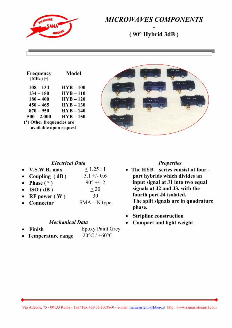
Electrical Data Properties • V.S.W.R. max < 1.25 : 1 • Coupling ( dB ) 3.1 +/- 0.6 • Phase ( ° ) 90° +/- 2 • ISO ( dB ) > 20 • RF power ( W ) 30 • Connector SMA – N type
• The HYB – series consist of four - port hybrids which divides an input signal at J1 into two equal signals at J2 and J3, with the fourth port J4 isolated. The split signals are in quadrature phase.
• Stripline construction Mechanical Data • Compact and light weight
• Finish Epoxy Paint Grey • Temperature range -20°C / +60°C
Frequency ( MHz ) (*)
Model
108 – 134 HYB – 100 134 – 180 HYB – 110 180 – 400 HYB – 120 450 – 465 HYB – 130 870 – 950 HYB – 140
500 – 2.000 HYB – 150 (*) Other frequencies are available upon request
MICROWAVES COMPONENTS -
( 90° Hybrid 3dB )

Via Atteone, 75 - 00133 Roma - Tel / Fax +39 06 2003860 - e-mail : [email protected] http : www.samasistemisrl.com
REQUIREMENT
• Frequency range 8.5 – 9.6 GHz • V.S.W.R. ( IN – OUT ) < 1.4 : 1 • Insertion loss < 3 dB • RF level input 100 – 200 mW • Isolation > 20 dB • Leveling set range
• 100 mW input +17 dBm to 5 dB • 200 mW input +20 dBm to 5 dB
GENERAL FEATURES
• The Automatic Leveling Control
Assembly is an X – band strip line microwave circuit, operating over the frequency range of 8.5 to 9.6 GHz
MICROWAVE COMPONENTS -
( Automatic Leveling Control )

Via Atteone, 75 - 00133 Roma - Tel / Fax +39 06 2003860 - e-mail : [email protected] http : www.samasistemisrl.com
REQUIREMENT • Frequency range 8.5 – 9.6 GHz • V.S.W.R. ( IN – OUT ) < 1.7 : 1
Insertion loss ( at 9 GHz ) - primary path loss 8.5 dB max +/- .5
- secondary path loss fixed coupler 38 +/- 2 dB • S1 and S2 switching - turn on , 50 % level < 50 ns - turn off , 50 % level < 50 ns - switch atten. high loss state > 85 dB
GENERAL FEATURES
• The Modulator Circuit Assembly is an X – band strip line microwave circuit that operates over the frequency range of 8.5 to 9.6 GHz.
The circuit contains two 20 dB directional coupler, two pin diode switches and three pin diode attenuators.
MICROWAVE COMPONENTS -
Modulator Circuit Assembly
Via Atteone, 75 - 00133 Roma - Tel / Fax +39 06 2003860 - e-mail : [email protected] http : www.samasistemisrl.com
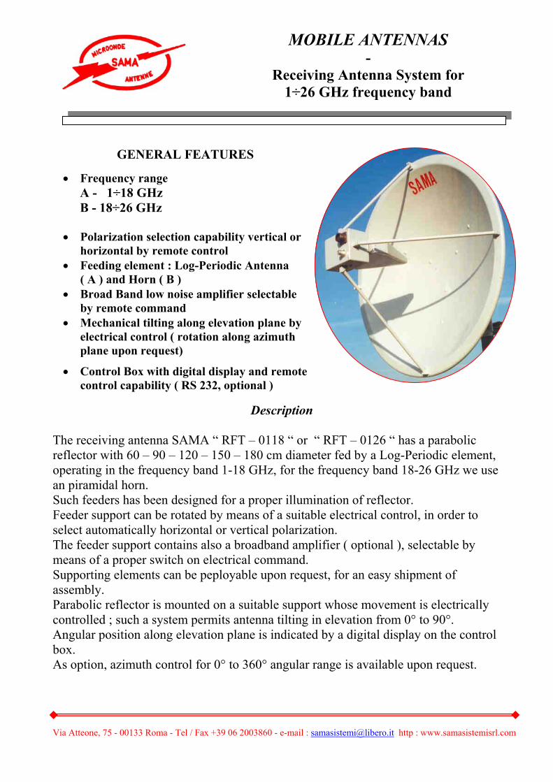
Description The receiving antenna SAMA “ RFT – 0118 “ or “ RFT – 0126 “ has a parabolic reflector with 60 – 90 – 120 – 150 – 180 cm diameter fed by a Log-Periodic element, operating in the frequency band 1-18 GHz, for the frequency band 18-26 GHz we use an piramidal horn. Such feeders has been designed for a proper illumination of reflector. Feeder support can be rotated by means of a suitable electrical control, in order to select automatically horizontal or vertical polarization. The feeder support contains also a broadband amplifier ( optional ), selectable by means of a proper switch on electrical command. Supporting elements can be peployable upon request, for an easy shipment of assembly. Parabolic reflector is mounted on a suitable support whose movement is electrically controlled ; such a system permits antenna tilting in elevation from 0° to 90°. Angular position along elevation plane is indicated by a digital display on the control box. As option, azimuth control for 0° to 360° angular range is available upon request.
GENERAL FEATURES
• Frequency range A - 1÷18 GHz B - 18÷26 GHz
• Polarization selection capability vertical or
horizontal by remote control • Feeding element : Log-Periodic Antenna
( A ) and Horn ( B ) • Broad Band low noise amplifier selectable
by remote command • Mechanical tilting along elevation plane by
electrical control ( rotation along azimuth plane upon request)
• Control Box with digital display and remote control capability ( RS 232, optional )
MOBILE ANTENNAS -
Receiving Antenna System for 1÷26 GHz frequency band

Via Atteone, 75 - 00133 Roma - Tel / Fax +39 06 2003860 - e-mail : [email protected] http : www.samasistemisrl.com
Options • Antenna is delivered with Control Box for polarization selection and connecting
cable ( 15 meter long )
The following options are available upon request:
• Broadband amplifier ( 1 – 18 GHz and 18 – 26 GHz ) with typical gain of 22 dB and NF = < 4 dB
• Electrical motor for 0° to 90° tilting in elevation, with control box and digital display
• Electrical motor for 0° to 360° azimuth scan
• RS – 232 interface for motors control, polarization and amplifier selection by PC
• Low loss RF coaxial cable
Control Box has a 19” standard cabinet and is well suited to drive motor for elevation tilting
It includes the connecting cable and permits polarization and amplifier selection.
MOBILE ANTENNAS
Via Atteone, 75 - 00133 Roma - Tel / Fax +39 06 2003860 - e-mail : [email protected] http : www.samasistemisrl.com
MOBILE ANTENNAS -
( Automatic Tracking Telemetry Antenna System )
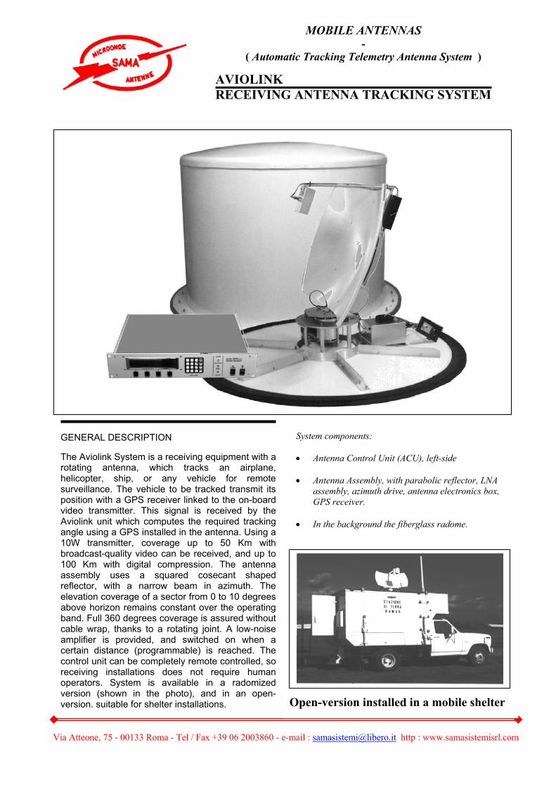
AVIOLINK RECEIVING ANTENNA TRACKING SYSTEM
GENERAL DESCRIPTION The Aviolink System is a receiving equipment with a rotating antenna, which tracks an airplane, helicopter, ship, or any vehicle for remote surveillance. The vehicle to be tracked transmit its position with a GPS receiver linked to the on-board video transmitter. This signal is received by the Aviolink unit which computes the required tracking angle using a GPS installed in the antenna. Using a 10W transmitter, coverage up to 50 Km with broadcast-quality video can be received, and up to 100 Km with digital compression. The antenna assembly uses a squared cosecant shaped reflector, with a narrow beam in azimuth. The elevation coverage of a sector from 0 to 10 degrees above horizon remains constant over the operating band. Full 360 degrees coverage is assured without cable wrap, thanks to a rotating joint. A low-noise amplifier is provided, and switched on when a certain distance (programmable) is reached. The control unit can be completely remote controlled, so receiving installations does not require human operators. System is available in a radomized version (shown in the photo), and in an open-version, suitable for shelter installations. Open-version installed in a mobile shelter
System components: • Antenna Control Unit (ACU), left-side • Antenna Assembly, with parabolic reflector, LNA
assembly, azimuth drive, antenna electronics box, GPS receiver.
• In the background the fiberglass radome.
Via Atteone, 75 - 00133 Roma - Tel / Fax +39 06 2003860 - e-mail : [email protected] http : www.samasistemisrl.com
ANTENNA SYSTEM
Frequency range (other bands available on request) 2.4 – 2.7 Ghz Polarization (E) Vertical Antenna gain > 25 dB Beamwidth, -3 dB Azimuth Elevation
8 ° deg 10 ° deg
Sidelobes < 15 dB LNA noise figure < 1 dB @ 2.5 GHz LNA Gain > 35 dB @ 2.5 GHz Max tracking speed 10 deg/sec
Azimuth position resolution 0.1 deg
Mating connectors RF: type-N (F) Control: MIL-C 10 pin (F)
Antenna GPS sensor Sirf 12 channel – NMEA
Radome Fiberglass. IP65 compliant
Dimensions 120 cm (H), 130 cm (Dia)
Weight 60 Kg. CONTROL UNIT
Processor 80386 (40 MHz)
Control loop Digital/analog servo system
GPS Position data sampling 1 sec Position Interpolator 100 msec Antenna tracking sampling speed 20 msec Display update 100 msec Datalink NMEA 0183, 4800 bps. Signal interfaces RS-232 Antenna assy power supply 28 Vdc, max 2 A
Dimensions, weight Rack 19”, 2U. Depth 40 cm. max 10 Kg
Power 220 Vac – 100 VA max (option 115 Vac)
MOBILE ANTENNAS
Via Atteone, 75 - 00133 Roma - Tel / Fax +39 06 2003860 - e-mail : [email protected] http : www.samasistemisrl.com
Via Atteone, 75 - 00133 Roma - Tel / Fax +39 06 2003860 - e-mail : [email protected] http : www.samasistemisrl.com

Via Atteone, 75 - 00133 Roma - Tel / Fax +39 06 2003860 - e-mail : [email protected] http : www.samasistemisrl.com
• SAMA SISTEMI S.r.l. and ECOENGINEERING propose consultancy
for analysis, design, measurement and monitoring of electromagnetic pollution.
The capability cover from low frequencies ( 50 Hz : high voltage lines ) up to 50 GHz. All the potenzial electromagnetic pollution source are verified : point to point system, broadcasting source, military systems, mobile installations, industrial machines, etc……. We are able to certificate all the design source with respect to the local laws. Our consultancy and design services are offered to public administrations, companies and associations. Design consultancy, measurement and certifications are available also for acoustic pollutions, applicable to private or industrial areas.
Via Atteone, 75 - 00133 Roma - Tel / Fax +39 06 2003860 - e-mail : [email protected] http : www.samasistemisrl.com
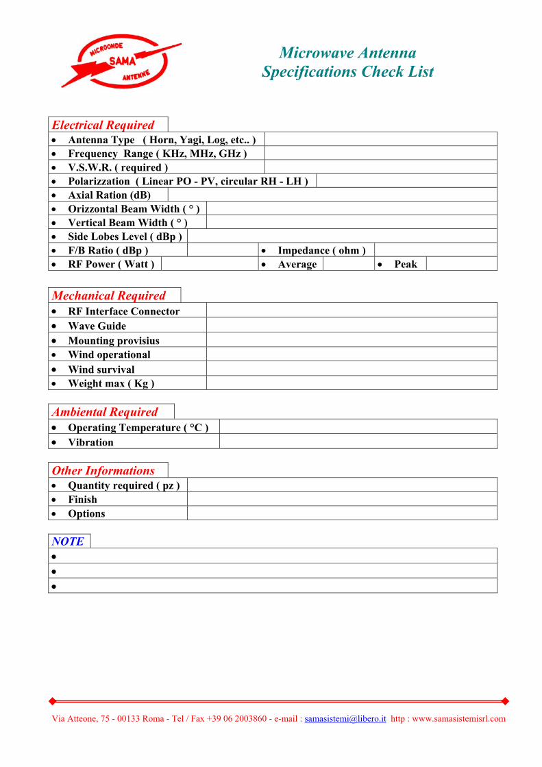
Electrical Required • Antenna Type ( Horn, Yagi, Log, etc.. ) • Frequency Range ( KHz, MHz, GHz ) • V.S.W.R. ( required ) • Polarizzation ( Linear PO - PV, circular RH - LH ) • Axial Ration (dB) • Orizzontal Beam Width ( ° ) • Vertical Beam Width ( ° ) • Side Lobes Level ( dBp ) • F/B Ratio ( dBp ) • Impedance ( ohm ) • RF Power ( Watt ) • Average • Peak
Mechanical Required • RF Interface Connector • Wave Guide • Mounting provisius • Wind operational • Wind survival • Weight max ( Kg ) Ambiental Required • Operating Temperature ( °C ) • Vibration Other Informations • Quantity required ( pz ) • Finish • Options NOTE • • •
Microwave Antenna Specifications Check List

Via Atteone, 75 - 00133 Roma - Tel / Fax +39 06 2003860 - e-mail : [email protected] http : www.samasistemisrl.com
ISO 9001 CERTIFIED
Study Application Microwave
Antennas
CCCAAATTTAAALLLOOOGGG
Civil and Military Telecommunication Sistems
NOTE This product brochure contain accurate data available at printing date. We reserve the right, however, to make changes at any time, without notice, in specifications, materials, equipment, models, price and availability about this product. SAMA SISTEMI S.r.l. Via Atteone, 75 00133 Rome – ITALY Phone/fax: +39 6 2003860 Website: www.samasistemisrl.com, e-mail: [email protected]
Representative / dealer:
SSSAAAMMMAAA SSSIIISSSTTTEEEMMMIII SSS...rrr...lll...