cpx terminal - festo€¦-fb-epl-…-vmpal…-epl-…-vaba-s6-1-x ... this manual is intended...
TRANSCRIPT
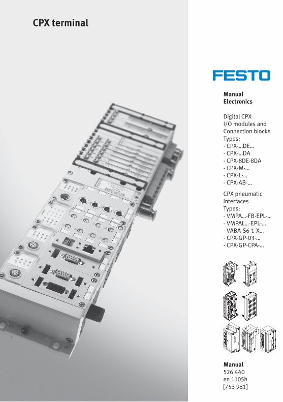
ManualElectronics
Digital CPXI/O modules andConnection blocksTypes:- CPX-…DE…- CPX-…DA- CPX-8DE-8DA- CPX-M-…- CPX-L-…- CPX-AB-…
CPX pneumaticinterfacesTypes:- VMPA…-FB-EPL-…- VMPAL…-EPL-…- VABA-S6-1-X…- CPX-GP-03-…- CPX-GP-CPA-…
CPX terminal
Manual526 440en 1105h[753 981]


Contents and general safety instructions
IFesto P.BE-CPX-EA-EN en 1105h
Original de. . . . . . . . . . . . . . . . . . . . . . . . . . . . . . . . . . . . . . .
Edition en 1105h. . . . . . . . . . . . . . . . . . . . . . . . . . . . . . . . . .
Designation P.BE-CPX-EA-EN. . . . . . . . . . . . . . . . . . . . . . . . .
Order no. 526 440. . . . . . . . . . . . . . . . . . . . . . . . . . . . . . . . .
� (Festo AG & Co. KG, D-73726 Esslingen, 2011)Internet: http://www.festo.comE-Mail: [email protected]
The reproduction of this document and disclosure to thirdparties and the utilisation or communication of its contentswithout explicit authorization is prohibited. Offenders willbe held liable for compensation of damages. All rightsreserved, in particular the right to carry out patent, utilitymodel or ornamental design registrations.

Contents and general safety instructions
II Festo P.BE-CPX-EA-EN en 1105h
CAGE CLAMP®, TORX®, HARAX® and SPEEDCON® are registered trademarks of therespective trademark owners in certain countries.

Contents and general safety instructions
IIIFesto P.BE-CPX-EA-EN en 1105h
Contents
Intended use VI. . . . . . . . . . . . . . . . . . . . . . . . . . . . . . . . . . . . . . . . . . . . . . . . . . . . . . . . . .
Areas of application and approval by authorities VII. . . . . . . . . . . . . . . . . . . . . . . . . . . . .
Target group VII. . . . . . . . . . . . . . . . . . . . . . . . . . . . . . . . . . . . . . . . . . . . . . . . . . . . . . . . . .
Service VII. . . . . . . . . . . . . . . . . . . . . . . . . . . . . . . . . . . . . . . . . . . . . . . . . . . . . . . . . . . . . . .
Important user instructions VIII. . . . . . . . . . . . . . . . . . . . . . . . . . . . . . . . . . . . . . . . . . . . . .
Notes on the use of this manual X. . . . . . . . . . . . . . . . . . . . . . . . . . . . . . . . . . . . . . . . . . .
Structure of a CPX terminal XI. . . . . . . . . . . . . . . . . . . . . . . . . . . . . . . . . . . . . . . . . . . . . .
CPX I/O modules and connection blocks XII. . . . . . . . . . . . . . . . . . . . . . . . . . . . . . . . . . . .
CPX pneumatic interfaces XIV. . . . . . . . . . . . . . . . . . . . . . . . . . . . . . . . . . . . . . . . . . . . . . . .
MPA pneumatic modules XIV. . . . . . . . . . . . . . . . . . . . . . . . . . . . . . . . . . . . . . . . . . . . . . . .
Diagnosis via the fieldbus or a network XIV. . . . . . . . . . . . . . . . . . . . . . . . . . . . . . . . . . . . .
1. Overview and connection blocks for CPX I/O modules 1-1. . . . . . . . . . . . . . . .
1.1 Components of an I/O module 1-3. . . . . . . . . . . . . . . . . . . . . . . . . . . . . . . . . . . .
1.2 Connection technology 1-4. . . . . . . . . . . . . . . . . . . . . . . . . . . . . . . . . . . . . . . . . .
1.2.1 Display and connecting elements 1-8. . . . . . . . . . . . . . . . . . . . . . . . . . .
1.2.2 Combinations of I/O modules and connection blocks 1-10. . . . . . . . . .
1.2.3 Connecting the cables and plugs to the connection blocks 1-13. . . . . .
1.3 Assembly 1-23. . . . . . . . . . . . . . . . . . . . . . . . . . . . . . . . . . . . . . . . . . . . . . . . . . . . .
1.3.1 Fitting the connection blocks 1-24. . . . . . . . . . . . . . . . . . . . . . . . . . . . . .
1.3.2 Fitting the screening plates 1-28. . . . . . . . . . . . . . . . . . . . . . . . . . . . . . . .
2. Digital CPX input modules 2-1. . . . . . . . . . . . . . . . . . . . . . . . . . . . . . . . . . . . . . .
2.1 Function of the input modules 2-3. . . . . . . . . . . . . . . . . . . . . . . . . . . . . . . . . . . . .
2.2 Assembly 2-4. . . . . . . . . . . . . . . . . . . . . . . . . . . . . . . . . . . . . . . . . . . . . . . . . . . . .
2.3 Installation 2-5. . . . . . . . . . . . . . . . . . . . . . . . . . . . . . . . . . . . . . . . . . . . . . . . . . . .
2.3.1 Input module CPX-4DE 2-6. . . . . . . . . . . . . . . . . . . . . . . . . . . . . . . . . . .
2.3.2 Input module CPX-8DE 2-11. . . . . . . . . . . . . . . . . . . . . . . . . . . . . . . . . . .
2.3.3 Input module CPX-8DE-D with channel diagnosis 2-16. . . . . . . . . . . . . .
2.3.4 Input module CPX-8NDE 2-21. . . . . . . . . . . . . . . . . . . . . . . . . . . . . . . . . .
2.3.5 Input module CPX-16DE 2-26. . . . . . . . . . . . . . . . . . . . . . . . . . . . . . . . . .
2.3.6 Input module CPX-M-16DE-D with channel diagnosis 2-29. . . . . . . . . . .
2.3.7 Input module CPX-L-16DE-16-KL-3POL 2-31. . . . . . . . . . . . . . . . . . . . . .

Contents and general safety instructions
IV Festo P.BE-CPX-EA-EN en 1105h
2.4 Instructions on commissioning 2-32. . . . . . . . . . . . . . . . . . . . . . . . . . . . . . . . . . . .
2.4.1 Parameters of the input modules 2-32. . . . . . . . . . . . . . . . . . . . . . . . . . .
2.5 Diagnosis 2-36. . . . . . . . . . . . . . . . . . . . . . . . . . . . . . . . . . . . . . . . . . . . . . . . . . . . .
2.5.1 Error messages of the input modules 2-36. . . . . . . . . . . . . . . . . . . . . . .
2.5.2 LED display 2-38. . . . . . . . . . . . . . . . . . . . . . . . . . . . . . . . . . . . . . . . . . . .
2.5.3 Error handling and parameterisation 2-42. . . . . . . . . . . . . . . . . . . . . . . .
3. Digital CPX output modules 3-1. . . . . . . . . . . . . . . . . . . . . . . . . . . . . . . . . . . . . .
3.1 Function of the output modules 3-3. . . . . . . . . . . . . . . . . . . . . . . . . . . . . . . . . . .
3.2 Assembly 3-3. . . . . . . . . . . . . . . . . . . . . . . . . . . . . . . . . . . . . . . . . . . . . . . . . . . . .
3.3 Installation 3-4. . . . . . . . . . . . . . . . . . . . . . . . . . . . . . . . . . . . . . . . . . . . . . . . . . . .
3.3.1 Output module CPX-4DA 3-5. . . . . . . . . . . . . . . . . . . . . . . . . . . . . . . . . .
3.3.2 Output module CPX-8DA 3-11. . . . . . . . . . . . . . . . . . . . . . . . . . . . . . . . . .
3.3.3 High-current output module CPX-8DA-H 3-17. . . . . . . . . . . . . . . . . . . . .
3.4 Instructions on commissioning 3-22. . . . . . . . . . . . . . . . . . . . . . . . . . . . . . . . . . . .
3.4.1 Parameters of the output modules 3-22. . . . . . . . . . . . . . . . . . . . . . . . .
3.5 Diagnosis 3-25. . . . . . . . . . . . . . . . . . . . . . . . . . . . . . . . . . . . . . . . . . . . . . . . . . . . .
3.5.1 Error messages of the output modules 3-26. . . . . . . . . . . . . . . . . . . . . .
3.5.2 LED display 3-27. . . . . . . . . . . . . . . . . . . . . . . . . . . . . . . . . . . . . . . . . . . .
3.5.3 Error handling and parameterisation 3-29. . . . . . . . . . . . . . . . . . . . . . . .
4. Digital CPX multi I/O modules 4-1. . . . . . . . . . . . . . . . . . . . . . . . . . . . . . . . . . . .
4.1 Function of multi I/O modules 4-3. . . . . . . . . . . . . . . . . . . . . . . . . . . . . . . . . . . . .
4.2 Assembly 4-3. . . . . . . . . . . . . . . . . . . . . . . . . . . . . . . . . . . . . . . . . . . . . . . . . . . . .
4.3 Installation 4-4. . . . . . . . . . . . . . . . . . . . . . . . . . . . . . . . . . . . . . . . . . . . . . . . . . . .
4.3.1 Multi I/O module CPX-8DE-8DA 4-5. . . . . . . . . . . . . . . . . . . . . . . . . . . .
4.3.2 Multi I/O module CPX-L-8DE-8DA-… 4-9. . . . . . . . . . . . . . . . . . . . . . . . .
4.4 Instructions on commissioning 4-10. . . . . . . . . . . . . . . . . . . . . . . . . . . . . . . . . . . .
4.4.1 Parameters of the multi I/O modules type CPX-8DE-8DA 4-10. . . . . . . .
4.5 Diagnosis 4-16. . . . . . . . . . . . . . . . . . . . . . . . . . . . . . . . . . . . . . . . . . . . . . . . . . . . .
4.5.1 Error messages of the multi I/O modules 4-16. . . . . . . . . . . . . . . . . . . .
4.5.2 LED display 4-18. . . . . . . . . . . . . . . . . . . . . . . . . . . . . . . . . . . . . . . . . . . .
4.5.3 Error handling and parameterisation 4-21. . . . . . . . . . . . . . . . . . . . . . . .

Contents and general safety instructions
VFesto P.BE-CPX-EA-EN en 1105h
5. CPX pneumatic interfaces 5-1. . . . . . . . . . . . . . . . . . . . . . . . . . . . . . . . . . . . . . . .
5.1 Function of the CPX pneumatic interfaces 5-3. . . . . . . . . . . . . . . . . . . . . . . . . . .
5.1.1 Display and connecting elements 5-5. . . . . . . . . . . . . . . . . . . . . . . . . . .
5.2 Assembly 5-9. . . . . . . . . . . . . . . . . . . . . . . . . . . . . . . . . . . . . . . . . . . . . . . . . . . . .
5.3 Settings for configuring the pneumatics 5-10. . . . . . . . . . . . . . . . . . . . . . . . . . . . .
5.4 Installation 5-15. . . . . . . . . . . . . . . . . . . . . . . . . . . . . . . . . . . . . . . . . . . . . . . . . . . .
5.5 Instructions on commissioning, parameterisation 5-16. . . . . . . . . . . . . . . . . . . . .
5.6 Diagnosis 5-20. . . . . . . . . . . . . . . . . . . . . . . . . . . . . . . . . . . . . . . . . . . . . . . . . . . . .
5.6.1 Fault messages of the pneumatic interfaces 5-21. . . . . . . . . . . . . . . . . .
5.6.2 LED display 5-22. . . . . . . . . . . . . . . . . . . . . . . . . . . . . . . . . . . . . . . . . . . .
5.6.3 Error handling and parameterisation 5-24. . . . . . . . . . . . . . . . . . . . . . . .
A. Technical appendix A-1. . . . . . . . . . . . . . . . . . . . . . . . . . . . . . . . . . . . . . . . . . . . .
A.1 Technical specifications of the CPX connection blocks A-3. . . . . . . . . . . . . . . . .
A.2 Technical specifications of the CPX metal connection blocks A-4. . . . . . . . . . . .
A.3 Technical specifications of the CPX input modules A-5. . . . . . . . . . . . . . . . . . . .
A.4 Technical specifications of the CPX output modules A-7. . . . . . . . . . . . . . . . . . .
A.5 Technical specifications of the CPX multi I/O modules A-10. . . . . . . . . . . . . . . . .
A.6 Technical specifications of the pneumatic interfaces A-12. . . . . . . . . . . . . . . . . . .
B. Internal structure and circuitry examples B-1. . . . . . . . . . . . . . . . . . . . . . . . . .
B.1 Internal structure of the CPX I/O modules B-3. . . . . . . . . . . . . . . . . . . . . . . . . . .
B.2 Circuitry examples for CPX inputs and outputs B-8. . . . . . . . . . . . . . . . . . . . . . .
B.2.1 Circuitry examples for PNP inputs B-8. . . . . . . . . . . . . . . . . . . . . . . . . .
B.2.2 Circuitry examples for PNP outputs B-8. . . . . . . . . . . . . . . . . . . . . . . . .
B.2.3 Circuitry examples for NPN inputs B-9. . . . . . . . . . . . . . . . . . . . . . . . . .
B.2.4 Circuitry example with DUO cable B-10. . . . . . . . . . . . . . . . . . . . . . . . . .
B.2.5 Circuitry example with DNCV B-11. . . . . . . . . . . . . . . . . . . . . . . . . . . . . .
B.3 Accessories (CPX terminal) B-12. . . . . . . . . . . . . . . . . . . . . . . . . . . . . . . . . . . . . . .
C. Index C-1. . . . . . . . . . . . . . . . . . . . . . . . . . . . . . . . . . . . . . . . . . . . . . . . . . . . . . . . .
Contents and general safety instructions
VI Festo P.BE-CPX-EA-EN en 1105h
Intended use
The digital CPX I/O modules, CPX connection blocks and CPXpneumatic interfaces described in this manual have beendesigned exclusively for use in conjunction with CPX termin-als from Festo. The modules and pneumatic interfaces areonly to be used as follows:
– As specified in industrial applications.
– In an original condition, without any modifications by theuser.Only the conversions or modifications described in thedocumentation supplied with the product are permitted.
– In perfect technical condition.
If conventional accessory components such as sensors andactuators are connected, the specified limits for pressures,temperatures, electrical data, torques etc. should beobserved.Please observe the standards specified in the relevantchapters and comply with technical regulations, as well aswith national and local regulations.
Warning• Only use PELV circuits as per IEC/DIN EN 60204-1 forthe electric power supply (protective extra-low voltage,PELV).Also observe the general requirements for PELV circuitsin accordance with IEC/DIN EN 60204-1.
• Only use power sources that guarantee reliableelectrical isolation of the operating voltage as perIEC/DIN EN 60204-1.
Protection against electric shock (protection against directand indirect contact) is guaranteed in accordance withIEC/DIN EN 60204-1 by using PELV circuits (electrical equip-ment of machines, general requirements).

Contents and general safety instructions
VIIFesto P.BE-CPX-EA-EN en 1105h
Areas of application and approval by authorities
The products fulfil the requirements of EU directives and bearthe CE mark.
Standards and test values, which the products must complywith and fulfil, can be found in the section “Technicalappendix”. The product-relevant EU directive can be found inthe declaration of conformance.
Certificates and declarations of conformance for theseproducts can be found at www.festo.com.
Target group
This manual is intended exclusively for technicians trained incontrol and automation technology, who have experience ininstalling, commissioning, programming and diagnosing pro-grammable logic controllers (PLC) and fieldbus systems.
Service
Please consult your local Festo Service agent if you have anytechnical problems.
Contents and general safety instructions
VIII Festo P.BE-CPX-EA-EN en 1105h
Important user instructions
Danger categories
This description contains instructions on the possible dangerswhich can occur if the product is not used correctly. Theseinstructions are marked (Warning, Caution, etc), printed on ashaded background and marked additionally with a picto-gram. A distinction is made between the following dangerwarnings:
Warning... means that failure to observe this instruction may resultin serious personal injury or damage to property.
Caution... means that failure to observe this instruction may resultin personal injury or damage to property.
Note... means that failure to observe this instruction may resultin damage to property.
The following pictogram marks passages in the text whichdescribe activities with electrostatically sensitive devices:
Electrostatic sensitive devices: inappropriate handling canresult in damage to components.

Contents and general safety instructions
IXFesto P.BE-CPX-EA-EN en 1105h
Identification of specific information
The following pictograms designate texts that contain specialinformation.
Pictograms
Information:Recommendations, tips and references to other sources ofinformation.
Accessories:Information about necessary or useful accessories for theFesto product.
Environment:Information about the environmentally-friendly use of Festoproducts.
Text designations
• Bullet points indicate activities that may be carried out inany order.
1. Numerals denote activities which must be carried out inthe numerical order specified.
– Hyphens indicate general lists.

Contents and general safety instructions
X Festo P.BE-CPX-EA-EN en 1105h
Notes on the use of this manual
This manual contains general basic information about themethod of operation, fitting and installation of digital CPX I/Omodules, CPX connection blocks and CPX pneumatic inter-faces.
Information about MPA pneumatic and electronicmodules can be found in a separate description of typeP.BE-MPA-ELEKTRONIK-...
General basic information about the method of operation,fitting, installation and commissioning of CPX terminals canbe found in the CPX system description.
Special information about commissioning, parameterisingand diagnosing a CPX terminal with the bus node you areusing can be found in the appropriate manual for the busnode.
Information about further CPX modules can be found in themanual for the respective module.
An overview of the structure of the CPX terminal user docu-mentation is contained in the CPX system description.
Conventions
The special parameters of the modules are described in theindividual chapters. These appear in English on the handheldtype CPX-MMI-1.
[........] The data and parameters which appear in English on thehandheld are shown in square brackets in this manual, e.g.:
Input debounce time [Debounce time].
Contents and general safety instructions
XIFesto P.BE-CPX-EA-EN en 1105h
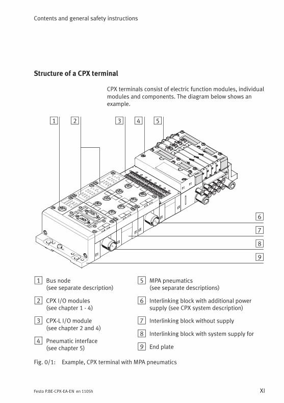
Structure of a CPX terminal
CPX terminals consist of electric function modules, individualmodules and components. The diagram below shows anexample.
1 2 3 4 5
6
7
8
9
1 Bus node(see separate description)
2 CPX I/O modules(see chapter 1 - 4)
3 CPX-L I/O module(see chapter 2 and 4)
4 Pneumatic interface(see chapter 5)
5 MPA pneumatics(see separate descriptions)
6 Interlinking block with additional powersupply (see CPX system description)
7 Interlinking block without supply
8 Interlinking block with system supply for
9 End plate
Fig. 0/1: Example, CPX terminal with MPA pneumatics

Contents and general safety instructions
XII Festo P.BE-CPX-EA-EN en 1105h
CPX I/O modules and connection blocks
I/O modules Typedesignation
Description Connection blocks andinterlinking modules
– CPX-4DE– CPX-8DE– CPX-16DE
– CPX-8DE-D
– CPX-8NDE
Input moduleswith 4, 8 or16 inputs, PNP
Input module with8 inputs andchannel diagnosis,PNP
Input module with8 inputs, negativelogic, NPN
The I/O modules eachconsist of the electronicmodule as well as aconnection block and aninterlinking block(see Fig. 1/1)
Connection blocks:– CPX-AB-4-M12x2-5POL– CPX-AB-4-M12x2-5POL-R– CPX-AB-8-M8-3POL– CPX-AB-8-M8-4POL– CPX-AB-8-KL-4POL– CPX-AB-1-SUB-BU-25POL– CPX-AB-4-HARX2-4POL– CPX-AB-4-M12-8POL– CPX-M-4-M12x2-5POL(Note the possible combina-tions in section 1.2.2).
Interlinking modules:– CPX-GE-EV– CPX-GE-EV-...
– CPX-4DA
– CPX-8DA
– CPX-8DA-H
Output modulewith 4 outputs,PNP
Output modulewith 8 outputs,PNP
High-currentoutput modulewith 8 outputs,PNP
– CPX-8DE-8DA Multi I/O module(input/outputmodule) with8 inputs and8 outputs, PNP
Tab. 0/1: Overview of I/O modules – part 1

Contents and general safety instructions
XIIIFesto P.BE-CPX-EA-EN en 1105h
I/O modules Typedesignation
Description Connection blocks andinterlinking modules
– CPX-M-16DE-D Input module with16 inputs andchannel diagnosis,PNP
The I/O modules eachconsist of the electronicmodule as well as aconnection block and aninterlinking module.
Connection block:– CPX-M-8-M12x2-5POL
Interlinking modules:– CPX-GE-EV– CPX-GE-EV-...
CPX-L-16DE-16-KL-3POL
Input module with16 inputs
CPX-L modules areintegrated in the interlinkingblock and are equipped with48 push-in terminals.
CPX-L-8DE-8DA-16-KL-3POL
Multi I/O module(input/outputmodule) with8 inputs and8 outputs, PNP
Tab. 0/2: Overview of I/O modules – part 2
Contents and general safety instructions
XIV Festo P.BE-CPX-EA-EN en 1105h
CPX pneumatic interfaces
An overview of CPX pneumatic interfaces can be found inTab. 5/1.
MPA pneumatic modules
Information about MPA pneumatic and electronic modules canbe found in the description of type P.BE-MPA-ELEKTRONIK-...
Diagnosis via the fieldbus or a network
Depending on the parameterisation, CPX I/O modules andCPX pneumatic interfaces register specific faults via thefieldbus or your network.
These can be evaluated via the:
– Status bits (system status)
– I/O diagnostic interface (system diagnosis)
– Module diagnosis
– Error numbers
Further information on diagnosis can be found in theCPX system description or in the description for the bus node.

Contents and general safety instructions
XVFesto P.BE-CPX-EA-EN en 1105h
The following product-specific terms and abbreviations areused in this manual:
Term/abbreviation Meaning
Bus node Provides the connection to specific fieldbuses/networks. Transmitscontrol signals to the connected modules and monitors their ability tofunction.
Connection block Replaceable upper part of module housing with connections
CPX modules Collective term for the various modules which can be integrated in aCPX terminal.
DIL switch Dual-in-line switches consist of several logic elements with which settingscan be made.
I Digital input
I/O diagnostic interface The I/O diagnostic interface is a bus-independent diagnostic interface atI/O level, permitting access to internal data of the CPX terminal.
I/O modules Collective term for the CPX modules which provide digital inputs andoutputs (CPX input modules and CPX output modules).
I/Os Digital inputs and outputs
Input module CPX input module
Interlinking block Lower part of the housing of a CPX module for linking the moduleelectrically with the CPX terminal. There are different variants with andwithout power supplies, as well as those made of plastic and metal.
O Digital output
Output module CPX output module
Pneumatic interface The pneumatic interface is the interface between the modular electricalperipherals and the pneumatics.
PLC/IPC Programmable logic controller/industrial PC
Status bits Internal inputs that supply coded common diagnostic messages.
Tab. 0/3: Product-specific abbreviations

Contents and general safety instructions
XVI Festo P.BE-CPX-EA-EN en 1105h
Overview and connection blocks for CPX I/O modules
1-1Festo P.BE-CPX-EA-EN en 1105h
Chapter 1
Type CPX-AB-4-M12x2-5POLCPX-AB-4-M12x2-5POL-R
CPX-M-4-M12x2-5POL
CPX-AB-8-M8-3POLCPX-AB-8-M8-4POLCPX-AB-8-KL-4POLCPX-AB-1-SUB-BU-25POLCPX-AB-4-HARX2-4POLCPX-AB-4-M12-8POL
CPX-M-8-M12x2-5POL
Overview and connection blocks for CPX I/O modules
1. Overview and connection blocks for CPX I/O modules
1-2 Festo P.BE-CPX-EA-EN en 1105h
Contents
1. Overview and connection blocks for CPX I/O modules 1-1. . . . . . . . . . . . . . . .
1.1 Components of an I/O module 1-3. . . . . . . . . . . . . . . . . . . . . . . . . . . . . . . . . . . .
1.2 Connection technology 1-4. . . . . . . . . . . . . . . . . . . . . . . . . . . . . . . . . . . . . . . . . .
1.2.1 Display and connecting elements 1-8. . . . . . . . . . . . . . . . . . . . . . . . . . .
1.2.2 Combinations of I/O modules and connection blocks 1-10. . . . . . . . . .
1.2.3 Connecting the cables and plugs to the connection blocks 1-13. . . . . .
1.3 Assembly 1-23. . . . . . . . . . . . . . . . . . . . . . . . . . . . . . . . . . . . . . . . . . . . . . . . . . . . .
1.3.1 Fitting the connection blocks 1-24. . . . . . . . . . . . . . . . . . . . . . . . . . . . . .
1.3.2 Fitting the screening plates 1-28. . . . . . . . . . . . . . . . . . . . . . . . . . . . . . . .
1. Overview and connection blocks for CPX I/O modules
1-3Festo P.BE-CPX-EA-EN en 1105h
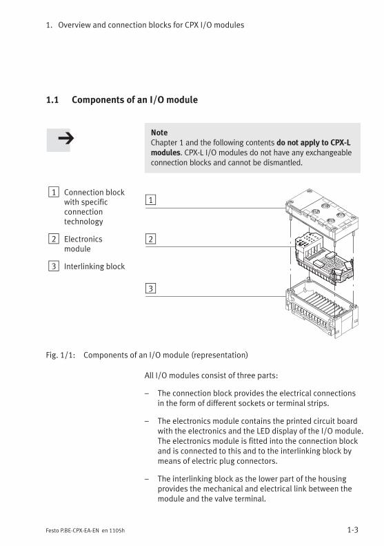
1.1 Components of an I/O module
NoteChapter 1 and the following contents do not apply to CPX-Lmodules. CPX-L I/O modules do not have any exchangeableconnection blocks and cannot be dismantled.
1 Connection blockwith specificconnectiontechnology
2 Electronicsmodule
3 Interlinking block
1
2
3
Fig. 1/1: Components of an I/O module (representation)
All I/O modules consist of three parts:
– The connection block provides the electrical connectionsin the form of different sockets or terminal strips.
– The electronics module contains the printed circuit boardwith the electronics and the LED display of the I/O module.The electronics module is fitted into the connection blockand is connected to this and to the interlinking block bymeans of electric plug connectors.
– The interlinking block as the lower part of the housingprovides the mechanical and electrical link between themodule and the valve terminal.

1. Overview and connection blocks for CPX I/O modules
1-4 Festo P.BE-CPX-EA-EN en 1105h
1.2 Connection technology
Individual connection requirements can be fulfilled withdifferent connection blocks. These connection blocks providethe required sockets or terminal strips for connecting thesensors and actuators, irrespective of the I/O module used.
Connection block Type Description
CPX-AB-4-M12x2-5POL 4 M12 sockets, 5-pin– Protection class IP65/IP67– One functional earth connection per
socket– Screening possibility via screening
plate (see Accessories,Appendix B.3)
CPX-AB-4-M12x2-5POL-R 4 M12 sockets with metal thread, 5-pin– Protection class IP65/IP67– One functional earth connection per
socket– Screening possibility via metal
thread– Enables M12 connectors and
SPEEDCON plug connectors to beused.
CPX-AB-8-M8-3POL 8 M8 sockets, 3-pin– Protection class IP65/IP67
Tab. 1/1: Connection technology – part 1
1. Overview and connection blocks for CPX I/O modules
1-5Festo P.BE-CPX-EA-EN en 1105h
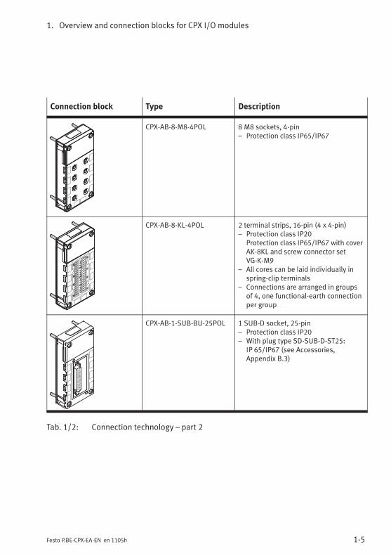
Connection block Type Description
CPX-AB-8-M8-4POL 8 M8 sockets, 4-pin– Protection class IP65/IP67
CPX-AB-8-KL-4POL 2 terminal strips, 16-pin (4 x 4-pin)– Protection class IP20
Protection class IP65/IP67 with coverAK-8KL and screw connector setVG-K-M9
– All cores can be laid individually inspring-clip terminals
– Connections are arranged in groupsof 4, one functional-earth connectionper group
CPX-AB-1-SUB-BU-25POL 1 SUB-D socket, 25-pin– Protection class IP20– With plug type SD-SUB-D-ST25:
IP 65/IP67 (see Accessories,Appendix B.3)
Tab. 1/2: Connection technology – part 2

1. Overview and connection blocks for CPX I/O modules
1-6 Festo P.BE-CPX-EA-EN en 1105h
Connection block Type Description
CPX-AB-4-HARX2-4POL 4 HARAX connections, 4-pin– Protection class IP65/IP67 with the
plugs intended for this purpose(see Accessories, Appendix B.3)
– Connection with insulationdisplacement technology
CPX-AB-4-M12-8POL 4 M12 sockets, 8-pin– Protection class IP65/IP67– Intended for connecting cylinder-
valve combination type DNCV– Connections are arranged in groups,
one functional-earth connection pergroup
– Screening possibility viascreening plate (see Accessories,Appendix B.3)
Tab. 1/3: Connection technology – part 3
1. Overview and connection blocks for CPX I/O modules
1-7Festo P.BE-CPX-EA-EN en 1105h
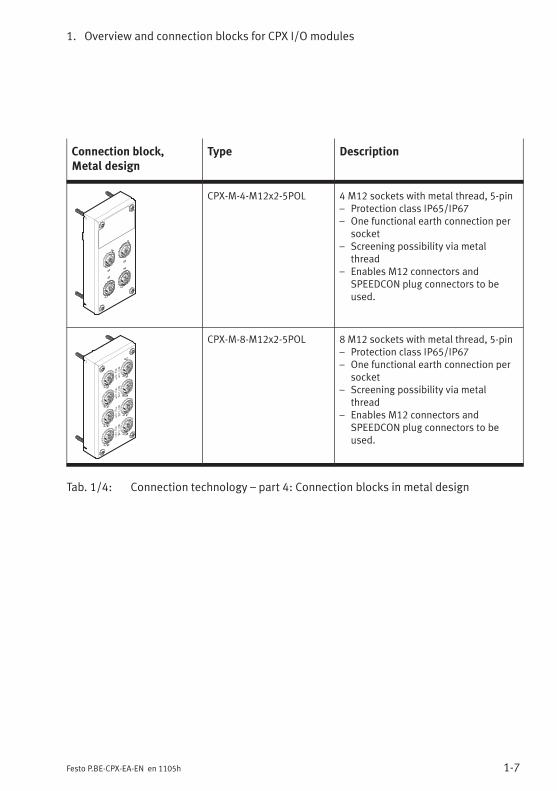
Connection block,Metal design
Type Description
CPX-M-4-M12x2-5POL 4 M12 sockets with metal thread, 5-pin– Protection class IP65/IP67– One functional earth connection per
socket– Screening possibility via metal
thread– Enables M12 connectors and
SPEEDCON plug connectors to beused.
CPX-M-8-M12x2-5POL 8 M12 sockets with metal thread, 5-pin– Protection class IP65/IP67– One functional earth connection per
socket– Screening possibility via metal
thread– Enables M12 connectors and
SPEEDCON plug connectors to beused.
Tab. 1/4: Connection technology – part 4: Connection blocks in metal design

1. Overview and connection blocks for CPX I/O modules
1-8 Festo P.BE-CPX-EA-EN en 1105h
1.2.1 Display and connecting elements
On most input and output modules the LEDs and the moduleidentification are visible through the transparent cover of theconnection block (see Fig. 1/2). The input module typeCPX-M-16DE-D is an exception (see Fig. 1/3).
1 Name plate
2 Module identification(here “8DI” for aninput module typeCPX-8DE)
3 LEDs:Inputs (green),Outputs (yellow),Faults (red)
4 Electrical connections(example)
5 Inscription fields foraddresses
0
1
2
3
8DI
4
5
6
7
1
2 3
4
5
Fig. 1/2: Display and connecting elements on modules with transparent cover
Use identity labels type IBS 6x10 for marking the addresses.

1. Overview and connection blocks for CPX I/O modules
1-9Festo P.BE-CPX-EA-EN en 1105h
1 Name plate
2 Electrical connections(example)
3 LEDs:Inputs (green),Outputs (yellow),Faults (red)
4 Holes for fasteningidentity labels
1
2
3
4
Fig. 1/3: Display and connecting elements on metal designs (here CPX-M-8-M12x2-5POL)
Use screws type CPX-M-M2,5X6-12X for fastening the identitylabels.
1. Overview and connection blocks for CPX I/O modules
1-10 Festo P.BE-CPX-EA-EN en 1105h
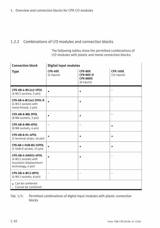
1.2.2 Combinations of I/O modules and connection blocks
The following tables show the permitted combinations ofI/O modules with plastic and metal connection blocks:
Connection block Digital input modules
Type CPX-4DE(4 inputs)
CPX-8DECPX-8DE-DCPX-8NDE(8 inputs)
CPX-16DE(16 inputs)
CPX-AB-4-M12x2-5POL(4 M12 sockets, 5-pin)
• •
–
CPX-AB-4-M12x2-5POL-R(4 M12 sockets withmetal thread, 5-pin)
• •
–
CPX-AB-8-M8-3POL(8 M8 sockets, 3-pin)
• •
–
CPX-AB-8-M8-4POL(8 M8 sockets, 4-pin)
– –•
CPX-AB-8-KL-4POL(2 terminal strips, 16-pin)
• • •
CPX-AB-1-SUB-BU-25POL(1 SUB-D socket, 25-pin)
• • •
CPX-AB-4-HARX2-4POL(4 M12 sockets withinsulation displacementtechnology, 4-pin)
• •
–
CPX-AB-4-M12-8POL(4 M12 sockets, 8-pin)
– – –
•Can be combined
– Cannot be combined
Tab. 1/5: Permitted combinations of digital input modules with plastic connectionblocks

1. Overview and connection blocks for CPX I/O modules
1-11Festo P.BE-CPX-EA-EN en 1105h
Connection block Digital output modules and multi I/O module
Type CPX-4DA(4 outputs)
CPX-8DA(8 outputs)
CPX-8DA-H(8 high currentoutputs)
CPX-8DE/8DA(8 inputs andoutputs)
CPX-AB-4-M12x2-5POL(4 M12 sockets, 5-pin)
• •
– –
CPX-AB-4-M12x2-5POL-R(4 M12 sockets withmetal thread, 5-pin)
• • •
–
CPX-AB-8-M8-3POL(8 M8 sockets, 3-pin)
• •
– –
CPX-AB-8-M8-4POL(8 M8 sockets, 4-pin)
• • •
–
CPX-AB-8-KL-4POL(2 terminal strips, 16-pin)
• • • •
CPX-AB-1-SUB-BU-25POL(1 SUB-D socket, 25-pin)
• • • •
CPX-AB-4-HARX2-4POL(4 M12 sockets withinsulation displacementtechnology, 4-pin)
• •
– –
CPX-AB-4-M12-8POL(4 M12 sockets, 8-pin)
– – –•
•Can be combined
– Cannot be combined
Tab. 1/6: Permitted combinations of digital output modules and the multi I/O modulewith plastic connection blocks

1. Overview and connection blocks for CPX I/O modules
1-12 Festo P.BE-CPX-EA-EN en 1105h
Connection block,Metal design
Digital input modules
Type CPX-4DE(4 inputs)
CPX-8DECPX-8DE-DCPX-8NDE(8 inputs)
CPX-16DE(16 inputs)
CPX-16DE-D(16 inputs)
CPX-M-4-M12x2-5POL(4 M12 sockets withmetal thread, 5-pin)
• •
– –
CPX-M-8-M12x2-5POL(8 M12 sockets withmetal thread, 5-pin)
– – –•
•Can be combined
– Cannot be combined
Tab. 1/7: Permitted combinations of digital input modules with metal connection blocks
Connection block,Metal design
Digital output modules and multi I/O module
Type CPX-4DA(4 outputs)
CPX-8DA(8 outputs)
CPX-8DA-H(8 high currentoutputs)
CPX-8DE/8DA(8 inputs andoutputs)
CPX-M-4-M12x2-5POL(4 M12 sockets withmetal thread, 5-pin)
• • •
–
CPX-M-8-M12x2-5POL(8 M12 sockets withmetal thread, 5-pin)
– – – –
•Can be combined
– Cannot be combined
Tab. 1/8: Permitted combinations of digital output modules and the multi I/O modulewith connection blocks in a metal design

1. Overview and connection blocks for CPX I/O modules
1-13Festo P.BE-CPX-EA-EN en 1105h
1.2.3 Connecting the cables and plugs to the connection blocks
Sensors and actuators must only be connected to theCPX I/O modules at the connection blocks. In this way,e.g. when an electronic module is replaced, the plugs andcables remain fitted in the connection block.
WarningUncontrolled movements of the connected actuators anduncontrolled movements of loose tubing can cause injuryto human beings or damage to property.
Before carrying out installation and maintenance work,switch off the following:
– Compressed air supply
– The operating and load voltage supplies.
The protection class of the I/O modules depends on the con-nection block used as well as on the plugs and protectivecaps used. Instructions can be found on the following pagesand in the Appendix A.1.
Use plugs and cables from the Festo range for connectingsensors and actuators (see Appendix B.3).

1. Overview and connection blocks for CPX I/O modules
1-14 Festo P.BE-CPX-EA-EN en 1105h
Connection blocks CPX-AB-4-M12x2-5POL (-R)CPX-M-4-M12x2-5POL,CPX-M-8-M12x2-5POL
NoteIn order that completely fitted modules with connectionblock CPX-AB-4-M12x2-5POL (-R) or CPX-M-...-M12x2-5POL comply with protection class IP 65/IP67:
• Use plugs and cables from the Festo range for connect-ing the sensors and actuators (see Appendix B.3).
• Tighten the union nuts of the plugs by hand.
• Seal unused sockets with protective caps type ISK-M12(see Appendix B.3: Accessories).
The connection blocks with metal thread (typeCPX-AB-4-M12x2-5POL-R and CPX-M-...-M12x2-5POL) enablefast locking systems to be used, e.g. SPEEDCON fromPhoenix Contact.
• When using fast locking systems follow themanufacturer’s instructions in order to comply withprotection class IP65/IP67.
Screening
– On plugs without metal housing:
• Connect the cable screening to pin 5 (functionalearth FE).
– On plugs with metal housing:
• Use the connection block with metal thread (typeCPX-AB-4-M12x2-5POL-R and CPX-M-...-M12x2-5POL).The metal thread of this connection block isconnected internally with pin 5 (functional earth FE).
or
• Connect the cable screening via the plug housing andthe screening plate to FE.

1. Overview and connection blocks for CPX I/O modules
1-15Festo P.BE-CPX-EA-EN en 1105h
Screening plate type CPX-AB-S-4-12
Connection blocks CPX-AB-4-M12x2-5POL (without metalthread) and CPX-AB-4-M12-8POL can be combined with ascreening plate. Depending on what you have ordered, thismay already be fitted on the connection block.
Instructions on subsequent fitting of the screening plate canbe found in section 1.3.2.
Electromagnetic compatibility can be improved withscreening plates, e.g. in environments heavily subjected tointerference or for analogue signals. For this purpose thescreening plates must be earthed at the flat contact intendedfor this purpose as per DIN 46 244 B2,8-1 (2.8 x 1 mm).
• Connect the earth cable of the screening plate with lowimpedance to the functional earth connection (FE) as perFig. 1/4.Screening plates lying next to each other are connectedtogether by spring clips and must not be connectedindividually to FE.
If the intended plugs are used (see Accessories,Appendix B.3), the plug housing will be connected to thefunctional earth via the spring contacts on the screeningplate.
• Before fitting the plugs screw the spring contacts as far aspossible onto the thread of the plug.
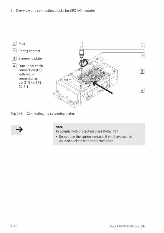
1. Overview and connection blocks for CPX I/O modules
1-16 Festo P.BE-CPX-EA-EN en 1105h
1 Plug
2 Spring contact
3 Screening plate
4 Functional earthconnection (FE)with bladeconnector asper DIN 46 245B2,8-1
1
2
3
4
Fig. 1/4: Connecting the screening plates
NoteTo comply with protection class IP65/IP67:
• Do not use the spring contacts if you have sealedunused sockets with protective caps.
1. Overview and connection blocks for CPX I/O modules
1-17Festo P.BE-CPX-EA-EN en 1105h
Connection blocks CPX-AB-8-M8-3POL and -4POL
NoteIn order that the completely fitted modules with connec-tion block CPX-AB-8-M8-3POL and -4POL comply withprotection class IP65/IP67:
• Use plugs and cables from the Festo range for connect-ing the sensors and actuators (see Appendix B.3).
• Tighten the union nuts of the plugs by hand.
• Seal unused sockets with protective caps type ISK-M8(Accessories).
Connection block CPX-AB-8-KL-4POL
The completely fitted connection block CPX-AB-8-KL-4POLcomplies with protection class IP20.
Specifications of the cable terminals:
– Conductor cross section: 0.08 ... 1.5 mm2
– Max. current: see chapter A.1
– Insulation removed: 5 ... 6 mm
Permitted copper conductors:
– Single wire, multi-wire, fine wire, also with tin-platedindividual cores
– Fine wire compressed
– Fine wire with core end sleeves (sealed against gas,crimped on) *)
– Fine wire with pin cable socket (sealed against gas,crimped on *)
*) If necessary, use next smaller conductor cross section

1. Overview and connection blocks for CPX I/O modules
1-18 Festo P.BE-CPX-EA-EN en 1105h
1 Screwdriver, blade2.5 x 0.4 mm
2 Unlocking opening(inside)
3 Cable
4 Terminal opening forinserting theconductors (outside)
5 Terminal strips
1
23
4
5
1
2
3
4 5
Fig. 1/5: Connecting the terminal strips
Fitting and removing the cables:
Note• To ensure reliable contact, only connect one conductorper terminal.
• Only insert cables into the terminal opening. The ter-minal will be damaged if a screwdriver is inserted intothe opening.
When connecting and disconnecting the cables:
1. Press the screwdriver with a light rotary movement to-wards the centre of the unlocking opening (see Fig. 1/5).The terminal will then be unlocked.
2. When the terminal is unlocked you can insert or pull outthe ends of the cable through the opening.
3. Remove the screwdriver from the unlocking opening. Thecable will then be securely locked.
1. Overview and connection blocks for CPX I/O modules
1-19Festo P.BE-CPX-EA-EN en 1105h
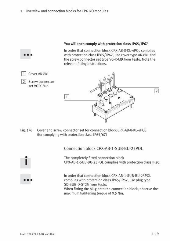
You will then comply with protection class IP65/IP67
In order that connection block CPX-AB-8-KL-4POL complieswith protection class IP65/IP67, use cover type AK-8KL andthe screw connector set type VG-K-M9 from Festo. Note therelevant fitting instructions.
1 Cover AK-8KL
2 Screw connectorset VG-K-M9
12
Fig. 1/6: Cover and screw connector set for connection block CPX-AB-8-KL-4POL(for complying with protection class IP65/67)
Connection block CPX-AB-1-SUB-BU-25POL
The completely fitted connection blockCPX-AB-1-SUB-BU-25POL complies with protection class IP20.
In order that connection block CPX-AB-1-SUB-BU-25POLcomplies with protection class IP65/IP67, use plug typeSD-SUB-D-ST25 from Festo.When fitting the plug onto the connection block, observe themaximum tightening torque of 0.5 Nm.

1. Overview and connection blocks for CPX I/O modules
1-20 Festo P.BE-CPX-EA-EN en 1105h
Connection block CPX-AB-4-HARX2-4POL
NoteIn order that the completely fitted modules with connec-tion block CPX-AB-4-HARX2-4POL comply with protectionclass IP65/IP67:
• Use plugs (type SEA-GS-HAR-4POL) from the Festorange (consisting of union nut, strain relief and splicingring) for connecting sensors and actuators.
• Tighten the union nuts of the plugs by hand.
• Seal the unused connecting sockets with protectivecaps from Harting (see Accessories, Appendix B.3).
Specifications of the cables for the connection blockCPX-AB-4-HARX2-4POL:
– Conductor cross section: 0.25 ... 0.5 mm2
– Strand cross-section: up to 0.1 mm
– Insulation material: PVC/PUR/PE
– Insulation thickness: max. 1.6 mm
– Core diameter: 1.2 mm ... 1.6 mm
– Cable outer diameter: 4.0 ... 5.1 mm

1. Overview and connection blocks for CPX I/O modules
1-21Festo P.BE-CPX-EA-EN en 1105h
Assembly
1 Cut the cable tolength and removethe coating. Push theunion nut and theseal insert onto theend of the cable.
2 Insert the ends of thecore into theappropriate slots ofthe splicing ring.
3 Place the seal andthe splicing ringtogether and cut offthe projecting coreends flush with thesplicing ring.
4 Insert the pre-fittedsplicing seal elementinto the contactsupport in theconnection block.Screw in the unionnut as far as possible.
1
2
4
3
1
2
4
3
Fig. 1/7: Connecting the cables to connection block CPX-AB
Dismantling
• Loosen the screw connector and remove the cores bypulling them out of the contacts.
The cores can be connected up to 10 times if the contactends are cut away each time (if the same core diameter isused). Cut off the used cable ends and repeat steps 2 to 4.

1. Overview and connection blocks for CPX I/O modules
1-22 Festo P.BE-CPX-EA-EN en 1105h
Connection block CPX-AB-4-M12-8POL
NoteIn order that the completely fitted modules with connec-tion block CPX-AB-4-M12-8POL comply with protectionclass IP65/IP67:
• Use cable type KM12-8GD8GS-2-PU from Festo for con-necting the cylinder-valve combination type DNCV orother sensors and actuators (see Appendix B.3)
• Tighten the union nuts of the plugs by hand.
• Seal unused sockets with protective caps type ISK-M12(Accessories).
Screening plate type CPX-AB-S-4-12
Connection block CPX-AB-4-M12-8POL can be combined witha screening plate. This can be ordered separately as anaccessory.
Instructions on subsequent fitting of the screening plate canbe found in section 1.3.2.Instructions on using the screening plates can be found withconnection block CPX-AB-4-M12x2-5POL.

1. Overview and connection blocks for CPX I/O modules
1-23Festo P.BE-CPX-EA-EN en 1105h
1.3 Assembly
WarningUncontrolled movements of the connected actuators anduncontrolled movements of loose tubing can cause injuryto human beings or damage to property.
Before carrying out installation and maintenance work,switch off the following:
– Compressed air supply
– The operating and load voltage supplies.
CautionInappropriate handling can result in damage to themodules.
• Do not touch any components.
• Observe the handling specifications for electrostaticsensitive devices.
• Discharge yourself before installing or removingsub-assemblies to protect the sub-assemblies fromstatic discharges.
Before the CPX terminal can be expanded or converted, itmust first be unscrewed and dismantled. Instructions on thiscan be found in the CPX system manual.
The CPX terminal does not need to be dismantled when con-nection blocks or electronic modules are fitted or removed.This also applies to the plugs and cables on the connectionblock.
1. Overview and connection blocks for CPX I/O modules
1-24 Festo P.BE-CPX-EA-EN en 1105h
1.3.1 Fitting the connection blocks
NoteHandle all modules and components of the CPX terminalwith great care. Pay particular attention to the following:
• Screws must be fitted exactly (otherwise threads will bedamaged).Screws should only be secured by hand. Screws must befitted so that the self-cutting threads can be used forplastic interlinking blocks.
• The specified torques must be observed.
• Threaded connections must be mounted free of offsetand mechanical tension.
• Check the seals for damage (IP65/IP67).
• Connecting surfaces must be clean (to ensure sealingeffect, avoid leakage and contact faults).
The screw connection between the connection block andthe interlinking block is designed to withstand at least10 fitting/removal cycles under observance of the instruc-tions for plastic interlinking blocks.
Also observe the mounting instructions in the packageinsert supplied with modules and components sub-sequently ordered.
CPX terminals are supplied from the factory completely fitted.It may be necessary to fit or remove the connection blocks forthe following reasons:
– replacing the connections,
– to simplify fitting the sensor plugs or cables.
It may be necessary to fit or remove the electronic modulesfor the following reasons:
– for changing the function of the I/O module (e.g. CPX-8DEinstead of CPX-4DE),
– for replacing defective electronic modules.

1. Overview and connection blocks for CPX I/O modules
1-25Festo P.BE-CPX-EA-EN en 1105h
Dismantling Dismantle the connection block as follows (see Fig. 1/8):
1. Loosen the 4 screws in the relevant connection block witha Torx screwdriver size T10.
2. Pull the connection block carefully and without tiltingaway from the electrical plug connection of the electronicmodule.
Only in cases where the electronic module is to be removed:
• Pull the electronic module carefully and without tiltingaway from the contact rails of the interlinking block.
1 Connection block
2 Screws
3 Electrical plugconnector
4 Electronicsmodule
5 Contact rails
6 Interlinking block
1
2
3
4
5
6
Fig. 1/8: Fitting/removing the I/O module (representation), not applicable forCPX-L modules
1. Overview and connection blocks for CPX I/O modules
1-26 Festo P.BE-CPX-EA-EN en 1105h
Fitting Fit the modules as follows (see Fig. 1/8):
Note• Please observe the instructions on combiningI/O modules and connection blocks in section 1.2.2.
• Please observe the instructions on combining andarranging modules on the CPX terminal in the CPXsystem manual.
NoteIf there is a combination of connection blocks and inter-linking blocks with metal on plastic or plastic on metal,always use the appropriate screws for the interlinkingblock (see Appendix B.3: Accessories):
– for plastic interlinking blocks: thread-cutting screws
– for metal interlinking blocks: screws with metric thread
Only in cases where the electronic module has been re-moved:
• Place the electronic module in interlinking block. Makesure that the grooves with the contact terminals on thebottom of the electronic module lie above the contactrails. Then push the electronic module carefully andwithout tilting as far as possible into the interlinkingblock.

1. Overview and connection blocks for CPX I/O modules
1-27Festo P.BE-CPX-EA-EN en 1105h
Fitting the connection blocks:
1. Only CPX-M-8-M12x2-5POL:Observe the following asymmetrically arranged featuresfor the correct alignment of the components:
– the centre electrical plug connector and
– the fibre-optic indicator for the error LED
2. Align the connection block over the interlinking block withthe electronic module. Make sure that the plugconnectors of the connection block are aligned exactlywith the connectors of the electronic module. Then pushthe connection block carefully and without tilting onto theinterlinking block.
3. Only tighten the screws by hand. Set the screws so thatthe self-cutting threads can be used.Tighten the screws with a Torx screwdriver (size T10) witha torque of 0.9 ... 1.1 Nm.
NoteCPX-L modules do not have any exchangeable connectionblocks. They cannot be dismantled.

1. Overview and connection blocks for CPX I/O modules
1-28 Festo P.BE-CPX-EA-EN en 1105h
1.3.2 Fitting the screening plates
A screening plate type CPX-AB-S-4-12 can be fitted onconnection blocks CPX-AB-4-M12x5-5POL andCPX-AB-4-M12-8POL. The connection block must be removedbefore fitting or dismantling.
Fitting Fit the screening plate as follows (see Fig. 1/9):
1. Dismantle the connection block (see section 1.3.1).
2. Snap the spring clips of the screening plate from aboveinto the appropriate recesses on the dismantled connec-tion block.
3. Fit the connection block.
Instructions on earthing the screening plate can be found insection 1.2.3.
Dismantling The screening plate must be removed in reverse sequence tothe fitting procedure.
1. Overview and connection blocks for CPX I/O modules
1-29Festo P.BE-CPX-EA-EN en 1105h
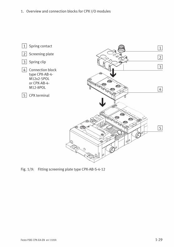
1 Spring contact
2 Screening plate
3 Spring clip
4 Connection blocktype CPX-AB-4-M12x2-5POLor CPX-AB-4-M12-8POL
5 CPX terminal
1
2
3
4
5
Fig. 1/9: Fitting screening plate type CPX-AB-S-4-12

1. Overview and connection blocks for CPX I/O modules
1-30 Festo P.BE-CPX-EA-EN en 1105h

Digital CPX input modules
2-1Festo P.BE-CPX-EA-EN en 1105h
Chapter 2
Type CPX-4DE
CPX-8DE
CPX-8DE-D
CPX-8NDE
CPX-16DE
CPX-M-16DE-D
CPX-L-16DE-16-KL-3POL
Digital CPX input modules

2. Digital CPX input modules
2-2 Festo P.BE-CPX-EA-EN en 1105h
Contents
2. Digital CPX input modules 2-1. . . . . . . . . . . . . . . . . . . . . . . . . . . . . . . . . . . . . . .
2.1 Function of the input modules 2-3. . . . . . . . . . . . . . . . . . . . . . . . . . . . . . . . . . . . .
2.2 Assembly 2-4. . . . . . . . . . . . . . . . . . . . . . . . . . . . . . . . . . . . . . . . . . . . . . . . . . . . .
2.3 Installation 2-5. . . . . . . . . . . . . . . . . . . . . . . . . . . . . . . . . . . . . . . . . . . . . . . . . . . .
2.3.1 Input module CPX-4DE 2-6. . . . . . . . . . . . . . . . . . . . . . . . . . . . . . . . . . .
2.3.2 Input module CPX-8DE 2-11. . . . . . . . . . . . . . . . . . . . . . . . . . . . . . . . . . .
2.3.3 Input module CPX-8DE-D with channel diagnosis 2-16. . . . . . . . . . . . . .
2.3.4 Input module CPX-8NDE 2-21. . . . . . . . . . . . . . . . . . . . . . . . . . . . . . . . . .
2.3.5 Input module CPX-16DE 2-26. . . . . . . . . . . . . . . . . . . . . . . . . . . . . . . . . .
2.3.6 Input module CPX-M-16DE-D with channel diagnosis 2-29. . . . . . . . . . .
2.3.7 Input module CPX-L-16DE-16-KL-3POL 2-31. . . . . . . . . . . . . . . . . . . . . .
2.4 Instructions on commissioning 2-32. . . . . . . . . . . . . . . . . . . . . . . . . . . . . . . . . . . .
2.4.1 Parameters of the input modules 2-32. . . . . . . . . . . . . . . . . . . . . . . . . . .
2.5 Diagnosis 2-36. . . . . . . . . . . . . . . . . . . . . . . . . . . . . . . . . . . . . . . . . . . . . . . . . . . . .
2.5.1 Error messages of the input modules 2-36. . . . . . . . . . . . . . . . . . . . . . .
2.5.2 LED display 2-38. . . . . . . . . . . . . . . . . . . . . . . . . . . . . . . . . . . . . . . . . . . .
2.5.3 Error handling and parameterisation 2-42. . . . . . . . . . . . . . . . . . . . . . . .

2. Digital CPX input modules
2-3Festo P.BE-CPX-EA-EN en 1105h
2.1 Function of the input modules
Input modules provide digital inputs in the valve terminal forconnecting sensors and for enabling e.g. cylinder positions tobe scanned. A distinction is made between the followingtypes:
Type Description
CPX-4DE Provides 4 digital inputs(as per IEC 61131-2 type 2, 24 V,positive logic – PNP).
CPX-8DE Provides 8 digital inputs(as per IEC 61131-2 type 2, 24 V,positive logic – PNP).
CPX-8DE-D Provides 8 digital inputs withchannel diagnosis(as per IEC 61131-2 type 2, 24 V,positive logic – PNP).
CPX-8NDE Provides 8 digital inputs(as per IEC 61131-2 type 2, 24 V,negative logic – NPN).
Tab. 2/1: Overview of input modules (part 1)

2. Digital CPX input modules
2-4 Festo P.BE-CPX-EA-EN en 1105h
Type Description
CPX-16DE Provides 16 digital inputs(as per IEC 61131-2 type 2, 24 V,positive logic – PNP).
CPX-M-16DE-D Provides 16 digital inputs withchannel diagnosis(as per IEC 61131-2 type 2, 24 V,positive logic – PNP).
CPX-L-16DE-16-KL-3POL
Provides 16 digital inputs(as per IEC 61131-2 type 1, 24 V,positive logic – PNP).CPX-L modules do not have anyexchangeable connectionblocks.
Tab. 2/2: Overview of input modules (part 2)
2.2 Assembly
See section 1.3.
2. Digital CPX input modules
2-5Festo P.BE-CPX-EA-EN en 1105h
2.3 Installation
WarningUncontrolled movements of the connected actuators anduncontrolled movements of loose tubing can cause injuryto human beings or damage to property.
Before carrying out installation and maintenance work,switch off the following:
– Compressed air supply
– The operating and load voltage supplies.
In the following sections you will find the pin assignments ofthe input modules for the different connection blocks.
Instructions on connecting the cables and plugs to the con-nection blocks can be found in section 1.2.3.
Power supply
The 24 V supply for the electronics and the inputs of theinput modules is provided via the operating voltage supplyfor the electronics/sensors (VEL/SEN).

2. Digital CPX input modules
2-6 Festo P.BE-CPX-EA-EN en 1105h
2.3.1 Input module CPX-4DE
Pin assignment CPX-4DE with connection blockCPX-AB-4-M12x2-5POL (-R), CPX-M-4-M12x2-5POL
I-module type CPX-4DE with connection blockCPX-AB-4-M12x2-5POL (-R), CPX-M-4-M12x2-5POL
Connection block Pin assignment X1, X2 LED Pin assignment X3, X4 LED
0
1
2
3
4DI
Example ofrepresentation withCPX-AB-4-M12x2-5POL
1
2
2
3
3
1
1
5
5
4
4
X1
X2
Socket X1:1: 24 VSEN2: Ix+13: 0 VSEN4: Ix5: FE1)
Socket X2:1: 24 VSEN2: n.c.3: 0 VSEN4: Ix+15: FE1)
1
0
1
1
2
2
3
3
1
1
5
5
4
4
X3
X4
Socket X31: 24 VSEN2: Ix+33: 0 VSEN4: Ix+25: FE1)
Socket X4:1: 24 VSEN2: n.c.3: 0 VSEN4: Ix+35: FE1)
3
2
3
Ix = Input xFE = Functional earthn.c. = Not connected
1 Connected internally1) In CPX-AB-4-M12x2-5POL-R and CPX-M-4-M12x2-5POL the metal thread
is connected to FE
Tab. 2/3: Pin assignment of I-module type CPX-4DE with connection blockCPX-AB-4-M12x2-5POL (-R), CPX-M-4-M12x2-5POL
Recommendation for the 4-input module:Use the Festo DUO cable in order to connect two sensors tosockets X1 and X3 with one plug at low cost.
CPX-AB-4-M12x2-5POL-R,CPX-M-4-M12x2-5POL
The metal thread of these connection blocks is connectedinternally with pin 5 (functional earth FE).

2. Digital CPX input modules
2-7Festo P.BE-CPX-EA-EN en 1105h
Pin assignment CPX-4DE with connection blockCPX-AB-8-M8-3POL
NoteSockets X1 to X8 on the connection block are markedaccordingly. The numbering of the sockets does notcorrespond to the input addresses.
I-module type CPX-4DE with connection block CPX-AB-8-M8-3POL
Connection block Pin assignment X1 to X4 LED Pin assignment X5 to X8 LED
0
1
2
3
4DI
X 1
X 2
X 3
X 4
X 5
X 6
X 7
X 8
1
X14 1
3
X24 1
3
X34 1
3
X44 1
3
Socket X1:1: 24 VSEN3: 0 VSEN4: Ix
Socket X2:1: 24 VSEN3: 0 VSEN4: Ix+1
Socket X3:1: 24 VSEN3: 0 VSEN4: Ix+1
Socket X4:1: 24 VSEN3: 0 VSEN4: n.c.
0
1
1
1
X54 1
3
X64 1
3
X74 1
3
X84 1
3
Socket X5:1: 24 VSEN3: 0 VSEN4: Ix+2
Socket X6:1: 24 VSEN3: 0 VSEN4: Ix+3
Socket X7:1: 24 VSEN3: 0 VSEN4: Ix+3
Socket X8:1: 24 VSEN3: 0 VSEN4: n.c.
2
3
3
Ix = Input xFE = Functional earthn.c. = Not connected
1 Connected internally
Tab. 2/4: Pin assignment of I-module type CPX-4DE with connection blockCPX-AB-8-M8-3POL
2. Digital CPX input modules
2-8 Festo P.BE-CPX-EA-EN en 1105h
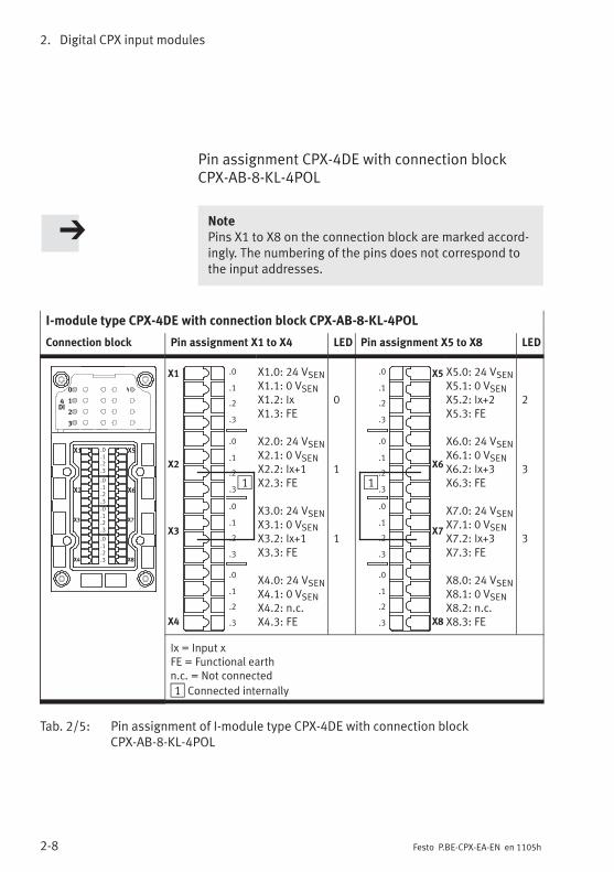
Pin assignment CPX-4DE with connection blockCPX-AB-8-KL-4POL
NotePins X1 to X8 on the connection block are marked accord-ingly. The numbering of the pins does not correspond tothe input addresses.
I-module type CPX-4DE with connection block CPX-AB-8-KL-4POL
Connection block Pin assignment X1 to X4 LED Pin assignment X5 to X8 LED
0
1
2
3
4DI
X1
X2
X3
X4
X5
X6
X7
X8
.0
.1
.2
.3
.0
.1
.2
.3
.0
.1
.2
.3
.0
.1
.2
.3
X1
X2
X3
X4
.0
.1
.2
.3
.0
.1
.2
.3
.0
.1
.2
.3
.0
.1
.2
.3
1
X1.0: 24 VSENX1.1: 0 VSENX1.2: IxX1.3: FE
X2.0: 24 VSENX2.1: 0 VSENX2.2: Ix+1X2.3: FE
X3.0: 24 VSENX3.1: 0 VSENX3.2: Ix+1X3.3: FE
X4.0: 24 VSENX4.1: 0 VSENX4.2: n.c.X4.3: FE
0
1
1
X5
X6
X7
X8
.0
.1
.2
.3
.0
.1
.2
.3
.0
.1
.2
.3
.0
.1
.2
.3
1
X5.0: 24 VSENX5.1: 0 VSENX5.2: Ix+2X5.3: FE
X6.0: 24 VSENX6.1: 0 VSENX6.2: Ix+3X6.3: FE
X7.0: 24 VSENX7.1: 0 VSENX7.2: Ix+3X7.3: FE
X8.0: 24 VSENX8.1: 0 VSENX8.2: n.c.X8.3: FE
2
3
3
Ix = Input xFE = Functional earthn.c. = Not connected
1 Connected internally
Tab. 2/5: Pin assignment of I-module type CPX-4DE with connection blockCPX-AB-8-KL-4POL

2. Digital CPX input modules
2-9Festo P.BE-CPX-EA-EN en 1105h
Pin assignment of CPX-4DE with connection blockCPX-AB-1-SUB-BU-25POL
I-module type CPX-4DE with connection block CPX-AB-1-SUB-BU-25POL
Connection block Pin assignment LED Pin assignment LED
0
1
2
3
4
DI
1
2
3
4
5
6
7
8
9
10
11
12
13
14
15
16
17
18
19
20
21
22
23
24
25
1: Ix2: Ix+13: Ix+14: n.c.5: 24 VSEN6: 0 VSEN7: 24 VSEN8: 0 VSEN9: 24 VSEN10: 24 VSEN11: 0 VSEN12: 0 VSEN13: FE
011
14: Ix+215: Ix+316: Ix+317: n.c.18: 24 VSEN19: 24 VSEN20: 24 VSEN21: 24 VSEN22: 0 VSEN23: 0 VSEN24: 0 VSEN25: FEHousing: FE
233
Ix = Input xFE = Functional earthn.c. = Not connected
Tab. 2/6: Pin assignment of I-module type CPX-4DE with connection blockCPX-AB-1-SUB-BU-25POL

2. Digital CPX input modules
2-10 Festo P.BE-CPX-EA-EN en 1105h
Pin assignment CPX-4DE with connection blockCPX-AB-4-HARX2-4POL
I-module type CPX-4DE with connection block CPX-AB-4-HARX2-4POL
Connection block Pin assignment X1, X2 LED Pin assignment X3, X4 LED
0
1
2
3
4
DI
1
23
14
X1
X22 3
1 4
Socket X1:1: 24 VSEN2: Ix+13: 0 VSEN4: Ix
Socket X2:1: 24 VSEN2: n.c.3: 0 VSEN4: Ix+1
1
0
1
1
23
14
X3
X42 3
1 4
Socket X31: 24 VSEN2: Ix+33: 0 VSEN4: Ix+2
Socket X4:1: 24 VSEN2: n.c.3: 0 VSEN4: Ix+3
3
2
3
Ix = Input xFE = Functional earthn.c. = Not connected
1 Connected internally
Tab. 2/7: Pin assignment of I-module type CPX-4DE with connection blockCPX-AB-4-HARX2-4POL

2. Digital CPX input modules
2-11Festo P.BE-CPX-EA-EN en 1105h
2.3.2 Input module CPX-8DE
Pin assignment CPX-8DE with connection blockCPX-AB-4-M12x2-5POL (-R), CPX-M-4-M12x2-5POL
I-module type CPX-8DE with connection blockCPX-AB-4-M12x2-5POL (-R), CPX-M-4-M12x2-5POL
Connection block Pin assignment X1, X2 LED Pin assignment X3, X4 LED
0
1
2
3
8DI
4
5
6
7
Example ofrepresentation withCPX-AB-4-M12x2-5POL
2
2
3
3
1
1
5
5
4
4
X1
X2
Socket X1:1: 24 VSEN2: Ix+13: 0 VSEN4: Ix5: FE1)
Socket X2:1: 24 VSEN2: Ix+33: 0 VSEN4: Ix+25: FE1)
1
0
3
2
2
2
3
3
1
1
5
5
4
4
X3
X4
Socket X31: 24 VSEN2: Ix+53: 0 VSEN4: Ix+45: FE1)
Socket X4:1: 24 VSEN2: Ix+73: 0 VSEN4: Ix+65: FE1)
5
4
7
6
Ix = Input xFE = Functional earth1) In CPX-AB-4-M12x2-5POL-R and CPX-M-4-M12x2-5POL the metal thread
is connected to FE
Tab. 2/8: Pin assignment of I-module type CPX-8DE with connection blockCPX-AB-4-M12x2-5POL (-R), CPX-M-4-M12x2-5POL
Recommendation for the 8-input module:Use the Festo DUO cable in order to connect two sensors withone plug at low cost.
CPX-AB-4-M12x2-5POL-R,CPX-M-4-M12x2-5POL
The metal thread of these connection blocks is connectedinternally with pin 5 (functional earth FE).

2. Digital CPX input modules
2-12 Festo P.BE-CPX-EA-EN en 1105h
Pin assignment CPX-8DE with connection blockCPX-AB-8-M8-3POL
I-module type CPX-8DE with connection block CPX-AB-8-M8-3POL
Connection block Pin assignment X1 to X4 LED Pin assignment X5 to X8 LED
0
1
2
3
8DI
4
5
6
7
X 1
X 2
X 3
X 4
X 5
X 6
X 7
X 8
X14 1
3
X24 1
3
X34 1
3
X44 1
3
Socket X1:1: 24 VSEN3: 0 VSEN4: Ix
Socket X2:1: 24 VSEN3: 0 VSEN4: Ix+1
Socket X3:1: 24 VSEN3: 0 VSEN4: Ix+2
Socket X4:1: 24 VSEN3: 0 VSEN4: Ix+3
0
1
2
3
X54 1
3
X64 1
3
X74 1
3
X84 1
3
Socket X5:1: 24 VSEN3: 0 VSEN4: Ix+4
Socket X6:1: 24 VSEN3: 0 VSEN4: Ix+5
Socket X7:1: 24 VSEN3: 0 VSEN4: Ix+6
Socket X8:1: 24 VSEN3: 0 VSEN4: Ix+7
4
5
6
7
Ix = Input xFE = Functional earth
Tab. 2/9: Pin assignment of I-module type CPX-8DE with connection blockCPX-AB-8-M8-3POL

2. Digital CPX input modules
2-13Festo P.BE-CPX-EA-EN en 1105h
Pin assignment CPX-8DE with connection blockCPX-AB-8-KL-4POL
I-module type CPX-8DE with connection block CPX-AB-8-KL-4POL
Connection block Pin assignment X1 to X4 LED Pin assignment X5 to X8 LED
0
1
2
3
8DI
4
5
6
7
X1
X2
X3
X4
X5
X6
X7
X8
.0
.1
.2
.3
.0
.1
.2
.3
.0
.1
.2
.3
.0
.1
.2
.3
X1
X2
X3
X4
.0
.1
.2
.3
.0
.1
.2
.3
.0
.1
.2
.3
.0
.1
.2
.3
X1.0: 24 VSENX1.1: 0 VSENX1.2: IxX1.3: FE
X2.0: 24 VSENX2.1: 0 VSENX2.2: Ix+1X2.3: FE
X3.0: 24 VSENX3.1: 0 VSENX3.2: Ix+2X3.3: FE
X4.0: 24 VSENX4.1: 0 VSENX4.2: Ix+3X4.3: FE
0
1
2
3
X5
X6
X7
X8
.0
.1
.2
.3
.0
.1
.2
.3
.0
.1
.2
.3
.0
.1
.2
.3
X5.0: 24 VSENX5.1: 0 VSENX5.2: Ix+4X5.3: FE
X6.0: 24 VSENX6.1: 0 VSENX6.2: Ix+5X6.3: FE
X7.0: 24 VSENX7.1: 0 VSENX7.2: Ix+6X7.3: FE
X8.0: 24 VSENX8.1: 0 VSENX8.2: Ix+7X8.3: FE
4
5
6
7
Ix = Input xFE = Functional earth
Tab. 2/10: Pin assignment of I-module type CPX-8DE with connection blockCPX-AB-8-KL-4POL

2. Digital CPX input modules
2-14 Festo P.BE-CPX-EA-EN en 1105h
Pin assignment of CPX-8DE with connection blockCPX-AB-1-SUB-BU-25POL
I-module type CPX-8DE with connection block CPX-AB-1-SUB-BU-25POL
Connection block Pin assignment LED Pin assignment LED
0
1
2
3
8
DI
4
5
6
7
1
2
3
4
5
6
7
8
9
10
11
12
13
14
15
16
17
18
19
20
21
22
23
24
25
1: Ix2: Ix+13: Ix+24: Ix+35: 24 VSEN6: 0 VSEN7: 24 VSEN8: 0 VSEN9: 24 VSEN10: 24 VSEN11: 0 VSEN12: 0 VSEN13: FE
0123
14: Ix+415: Ix+516: Ix+617: Ix+718: 24 VSEN19: 24 VSEN20: 24 VSEN21: 24 VSEN22: 0 VSEN23: 0 VSEN24: 0 VSEN25: FEHousing: FE
4567
Ix = Input xFE = Functional earth
Tab. 2/11: Pin assignment of I-module type CPX-8DE with connection blockCPX-AB-1-SUB-BU-25POL

2. Digital CPX input modules
2-15Festo P.BE-CPX-EA-EN en 1105h
Pin assignment CPX-8DE with connection blockCPX-AB-4-HARX2-4POL
I-module type CPX-8DE with connection block CPX-AB-2-HARX2-4POL
Connection block Pin assignment X1, X2 LED Pin assignment X3, X4 LED
0
1
2
3
8
DI
4
5
6
7
23
14
X1
X22 3
1 4
Socket X1:1: 24 VSEN2: Ix+13: 0 VSEN4: Ix
Socket X2:1: 24 VSEN2: Ix+33: 0 VSEN4: Ix+2
1
0
3
2
23
14
X3
X42 3
1 4
Socket X31: 24 VSEN2: Ix+53: 0 VSEN4: Ix+4
Socket X4:1: 24 VSEN2: Ix+73: 0 VSEN4: Ix+6
5
4
7
6
Ix = Input xFE = Functional earth
Tab. 2/12: Pin assignment of I-module type CPX-8DE with connection blockCPX-AB-4-HARX2-4POL

2. Digital CPX input modules
2-16 Festo P.BE-CPX-EA-EN en 1105h
2.3.3 Input module CPX-8DE-D with channel diagnosis
Pin assignment CPX-8DE-D with connection blockCPX-AB-4-M12x2-5POL (-R), CPX-M-4-M12x2-5POL
On these connection blocks only the sensor supplies forinputs Ix, Ix+2, Ix+4 and Ix+6 are available. These supplies areused in pairs by the inputs Ix/Ix+1, Ix+2/Ix+3, Ix+4/Ix+5 andIx+6/Ix+7. The diagnostic messages are therefore only for theinputs Ix, Ix+2, Ix+4 and Ix+6. The inputs Ix+1, Ix+3, Ix+5 andIx+7 do not generate a diagnostic message.
I-module type CPX-8DE-D with connection blockCPX-AB-4-M12x2-5POL (-R), CPX-M-4-M12x2-5POL
Connection block Pin assignment X1, X2 LED Pin assignment X3, X4 LED
Example of re-presentation withCPX-AB-4-M12x2-5POL
2
2
3
3
1
1
5
5
4
4
X1
X2
Socket X1:1: 24 VSENx2: Ix+13: 0 VSENx4: Ix5: FE1)
Socket X2:1: 24 VSENx+22: Ix+33: 0 VSENx+24: Ix+25: FE1)
1
0
3
2
2
2
3
3
1
1
5
5
4
4
X3
X4
Socket X31: 24 VSENx+42: Ix+53: 0 VSENx+44: Ix+45: FE1)
Socket X4:1: 24 VSENx+62: Ix+73: 0 VSENx+64: Ix+65: FE1)
5
4
7
6
Ix = Input xFE = Functional earth1) In CPX-AB-4-M12x2-5POL-R and CPX-M-4-M12x2-5POL the metal thread
is connected to FE
Tab. 2/13: Pin assignment CPX-8DE-D with connection block CPX-AB-4-M12x2-5POL (-R),CPX-M-4-M12x2-5POL
2. Digital CPX input modules
2-17Festo P.BE-CPX-EA-EN en 1105h
Recommendation for the 8-input module:Use the Festo DUO cable in order to connect two sensors withone plug at low cost.
CPX-AB-4-M12x2-5POL-R The metal thread of these connection blocks is connectedinternally with pin 5 (functional earth FE).
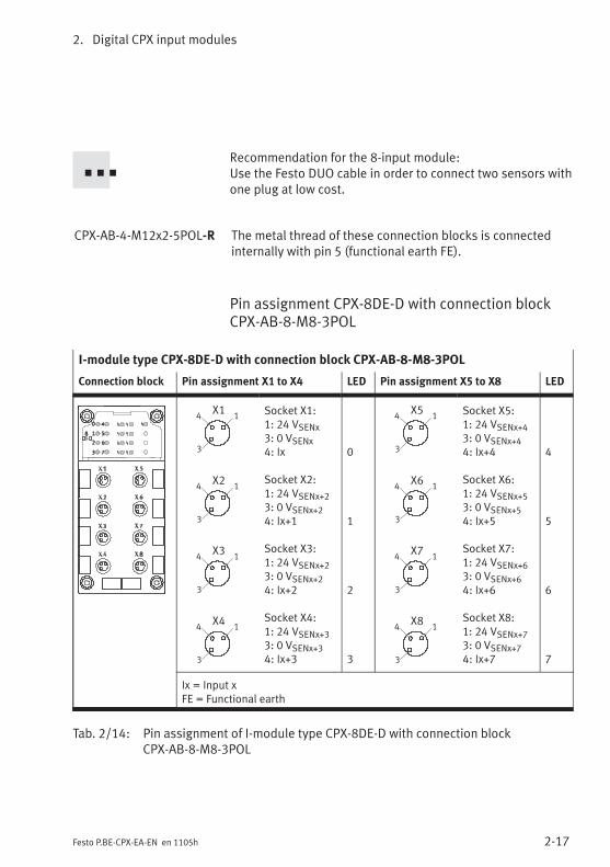
Pin assignment CPX-8DE-D with connection blockCPX-AB-8-M8-3POL
I-module type CPX-8DE-D with connection block CPX-AB-8-M8-3POL
Connection block Pin assignment X1 to X4 LED Pin assignment X5 to X8 LED
X14 1
3
X24 1
3
X34 1
3
X44 1
3
Socket X1:1: 24 VSENx3: 0 VSENx4: Ix
Socket X2:1: 24 VSENx+23: 0 VSENx+24: Ix+1
Socket X3:1: 24 VSENx+23: 0 VSENx+24: Ix+2
Socket X4:1: 24 VSENx+33: 0 VSENx+34: Ix+3
0
1
2
3
X54 1
3
X64 1
3
X74 1
3
X84 1
3
Socket X5:1: 24 VSENx+43: 0 VSENx+44: Ix+4
Socket X6:1: 24 VSENx+53: 0 VSENx+54: Ix+5
Socket X7:1: 24 VSENx+63: 0 VSENx+64: Ix+6
Socket X8:1: 24 VSENx+73: 0 VSENx+74: Ix+7
4
5
6
7
Ix = Input xFE = Functional earth
Tab. 2/14: Pin assignment of I-module type CPX-8DE-D with connection blockCPX-AB-8-M8-3POL

2. Digital CPX input modules
2-18 Festo P.BE-CPX-EA-EN en 1105h
Pin assignment CPX-8DE-D with connection blockCPX-AB-8-KL-4POL
I-module type CPX-8DE-D with connection block CPX-AB-8-KL-4POL
Connection block Pin assignment X1 to X4 LED Pin assignment X5 to X8 LED
X1
X2
X3
X4
.0
.1
.2
.3
.0
.1
.2
.3
.0
.1
.2
.3
.0
.1
.2
.3
X1.0: 24 VSENxX1.1: 0 VSENxX1.2: IxX1.3: FE
X2.0: 24 VSENx+2X2.1: 0 VSENx+2X2.2: Ix+1X2.3: FE
X3.0: 24 VSENx+2X3.1: 0 VSENx+2X3.2: Ix+2X3.3: FE
X4.0: 24 VSENx+3X4.1: 0 VSENx+3X4.2: Ix+3X4.3: FE
0
1
2
3
X5
X6
X7
X8
.0
.1
.2
.3
.0
.1
.2
.3
.0
.1
.2
.3
.0
.1
.2
.3
X5.0: 24 VSENx+4X5.1: 0 VSENx+4X5.2: Ix+4X5.3: FE
X6.0: 24 VSENx+5X6.1: 0 VSENx+5X6.2: Ix+5X6.3: FE
X7.0: 24 VSENx+6X7.1: 0 VSENx+6X7.2: Ix+6X7.3: FE
X8.0: 24 VSENx+7X8.1: 0 VSENx+7X8.2: Ix+7X8.3: FE
4
5
6
7
Ix = Input xFE = Functional earth
Tab. 2/15: Pin assignment of I-module type CPX-8DE-D with connection blockCPX-AB-8-KL-4POL

2. Digital CPX input modules
2-19Festo P.BE-CPX-EA-EN en 1105h
Pin assignment of CPX-8DE-D with connection blockCPX-AB-1-SUB-BU-25POL
I-module type CPX-8DE-D with connection block CPX-AB-1-SUB-BU-25POL
Connection block Pin assignment LED Pin assignment LED
1
2
3
4
5
6
7
8
9
10
11
12
13
14
15
16
17
18
19
20
21
22
23
24
25
1: Ix2: Ix+13: Ix+24: Ix+35: 24 VSENx+16: 0 VSENx+17: 24 VSENx+38: 0 VSENx+39: 24 VSENx10: 24 VSENx+211: 0 VSENx12: 0 VSENx+213: FE
0123
14: Ix+415: Ix+516: Ix+617: Ix+718: 24 VSENx+419: 24 VSENx+520: 24 VSENx+621: 24 VSENx+722: 0 VSENx+4...x+723: 0 VSENx+4...x+724: 0 VSENx+4...x+725: FEHousing: FE
4567
Ix = Input xFE = Functional earth
Tab. 2/16: Pin assignment of I-module type CPX-8DE-D with connection blockCPX-AB-1-SUB-BU-25POL

2. Digital CPX input modules
2-20 Festo P.BE-CPX-EA-EN en 1105h
Pin assignment CPX-8DE-D with connection blockCPX-AB-4-HARX2-4POL
On this connection block only the sensor supplies for inputsIx, Ix+2, Ix+4 and Ix+6 are available. These supplies are usedin pairs by the inputs Ix/Ix+1, Ix+2/Ix+3, Ix+4/Ix+5 andIx+6/Ix+7. The diagnostic messages are therefore only for theinputs Ix, Ix+2, Ix+4 and Ix+6. The inputs Ix+1, Ix+3, Ix+5 andIx+7 do not generate a diagnostic message.
I-module type CPX-8DE-D with connection block CPX-AB-2-HARX2-4POL
Connection block Pin assignment X1, X2 LED Pin assignment X3, X4 LED
23
14
X1
X22 3
1 4
Socket X1:1: 24 VSENx2: Ix+13: 0 VSENx4: Ix
Socket X2:1: 24 VSENx+22: Ix+33: 0 VSENx+24: Ix+2
1
0
3
2
23
14
X3
X42 3
1 4
Socket X31: 24 VSENx+42: Ix+53: 0 VSENx+44: Ix+4
Socket X4:1: 24 VSENx+62: Ix+73: 0 VSENx+64: Ix+6
5
4
7
6
Ix = Input xFE = Functional earth
Tab. 2/17: Pin assignment of I-module type CPX-8DE-D with connection blockCPX-AB-4-HARX2-4POL

2. Digital CPX input modules
2-21Festo P.BE-CPX-EA-EN en 1105h
2.3.4 Input module CPX-8NDE
Pin assignment of CPX-8NDE with connection blockCPX-AB-4-M12x2-5POL (-R), CPX-M-4-M12x2-5POL
I-module type CPX-8NDE with connection blockCPX-AB-4-M12x2-5POL (-R), CPX-M-4-M12x2-5POL
Connection block Pin assignment X1, X2 LED Pin assignment X3, X4 LED
0
1
2
3
8
NDI
4
5
6
7
Example ofrepresentation withCPX-AB-4-M12x2-5POL
2
2
3
3
1
1
5
5
4
4
X1
X2
Socket X1:1: 24 VSEN2: Ix+13: 0 VSEN4: Ix5: FE1)
Socket X2:1: 24 VSEN2: Ix+33: 0 VSEN4: Ix+25: FE1)
1
0
3
2
2
2
3
3
1
1
5
5
4
4
X3
X4
Socket X31: 24 VSEN2: Ix+53: 0 VSEN4: Ix+45: FE1)
Socket X4:1: 24 VSEN2: Ix+73: 0 VSEN4: Ix+65: FE1)
5
4
7
6
Ix = Input xFE = Functional earth1) In CPX-AB-4-M12x2-5POL-R and CPX-M-4-M12x2-5POL the metal thread
is connected to FE
Tab. 2/18: Pin assignment of I-module type CPX-8NDE with connection blockCPX-AB-4-M12x2-5POL (-R), CPX-M-4-M12x2-5POL
Recommendation for the 8-input module:Use the Festo DUO cable in order to connect two sensors withone plug at low cost.
CPX-AB-4-M12x2-5POL-R,CPX-M-4-M12x2-5POL
The metal thread of these connection blocks is connectedinternally with pin 5 (functional earth FE).
2. Digital CPX input modules
2-22 Festo P.BE-CPX-EA-EN en 1105h
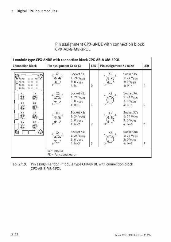
Pin assignment CPX-8NDE with connection blockCPX-AB-8-M8-3POL
I-module type CPX-8NDE with connection block CPX-AB-8-M8-3POL
Connection block Pin assignment X1 to X4 LED Pin assignment X5 to X8 LED
X 1
X 2
X 3
X 4
X 5
X 6
X 7
X 8
0
1
2
3
8
NDI
4
5
6
7
X14 1
3
X24 1
3
X34 1
3
X44 1
3
Socket X1:1: 24 VSEN3: 0 VSEN4: Ix
Socket X2:1: 24 VSEN3: 0 VSEN4: Ix+1
Socket X3:1: 24 VSEN3: 0 VSEN4: Ix+2
Socket X4:1: 24 VSEN3: 0 VSEN4: Ix+3
0
1
2
3
X54 1
3
X64 1
3
X74 1
3
X84 1
3
Socket X5:1: 24 VSEN3: 0 VSEN4: Ix+4
Socket X6:1: 24 VSEN3: 0 VSEN4: Ix+5
Socket X7:1: 24 VSEN3: 0 VSEN4: Ix+6
Socket X8:1: 24 VSEN3: 0 VSEN4: Ix+7
4
5
6
7
Ix = Input xFE = Functional earth
Tab. 2/19: Pin assignment of I-module type CPX-8NDE with connection blockCPX-AB-8-M8-3POL
2. Digital CPX input modules
2-23Festo P.BE-CPX-EA-EN en 1105h
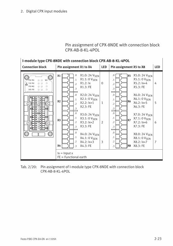
Pin assignment of CPX-8NDE with connection blockCPX-AB-8-KL-4POL
I-module type CPX-8NDE with connection block CPX-AB-8-KL-4POL
Connection block Pin assignment X1 to X4 LED Pin assignment X5 to X8 LED
X1
X2
X3
X4
X5
X6
X7
X8
.0
.1
.2
.3
.0
.1
.2
.3
.0
.1
.2
.3
.0
.1
.2
.3
0
1
2
3
8
NDI
4
5
6
7
X1
X2
X3
X4
.0
.1
.2
.3
.0
.1
.2
.3
.0
.1
.2
.3
.0
.1
.2
.3
X1.0: 24 VSENX1.1: 0 VSENX1.2: IxX1.3: FE
X2.0: 24 VSENX2.1: 0 VSENX2.2: Ix+1X2.3: FE
X3.0: 24 VSENX3.1: 0 VSENX3.2: Ix+2X3.3: FE
X4.0: 24 VSENX4.1: 0 VSENX4.2: Ix+3X4.3: FE
0
1
2
3
X5
X6
X7
X8
.0
.1
.2
.3
.0
.1
.2
.3
.0
.1
.2
.3
.0
.1
.2
.3
X5.0: 24 VSENX5.1: 0 VSENX5.2: Ix+4X5.3: FE
X6.0: 24 VSENX6.1: 0 VSENX6.2: Ix+5X6.3: FE
X7.0: 24 VSENX7.1: 0 VSENX7.2: Ix+6X7.3: FE
X8.0: 24 VSENX8.1: 0 VSENX8.2: Ix+7X8.3: FE
4
5
6
7
Ix = Input xFE = Functional earth
Tab. 2/20: Pin assignment of I-module type CPX-8NDE with connection blockCPX-AB-8-KL-4POL
2. Digital CPX input modules
2-24 Festo P.BE-CPX-EA-EN en 1105h
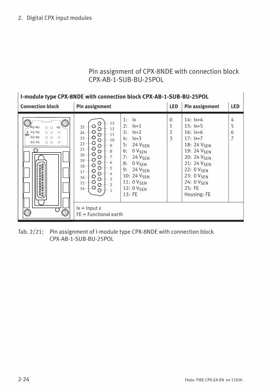
Pin assignment of CPX-8NDE with connection blockCPX-AB-1-SUB-BU-25POL
I-module type CPX-8NDE with connection block CPX-AB-1-SUB-BU-25POL
Connection block Pin assignment LED Pin assignment LED
0
1
2
3
8
NDI
4
5
6
7
1
2
3
4
5
6
7
8
9
10
11
12
13
14
15
16
17
18
19
20
21
22
23
24
25
1: Ix2: Ix+13: Ix+24: Ix+35: 24 VSEN6: 0 VSEN7: 24 VSEN8: 0 VSEN9: 24 VSEN10: 24 VSEN11: 0 VSEN12: 0 VSEN13: FE
0123
14: Ix+415: Ix+516: Ix+617: Ix+718: 24 VSEN19: 24 VSEN20: 24 VSEN21: 24 VSEN22: 0 VSEN23: 0 VSEN24: 0 VSEN25: FEHousing: FE
4567
Ix = Input xFE = Functional earth
Tab. 2/21: Pin assignment of I-module type CPX-8NDE with connection blockCPX-AB-1-SUB-BU-25POL

2. Digital CPX input modules
2-25Festo P.BE-CPX-EA-EN en 1105h
Pin assignment of CPX-8NDE with connection blockCPX-AB-4-HARX2-4POL
I-module type CPX-8NDE with connection block CPX-AB-2-HARX2-4POL
Connection block Pin assignment X1, X2 LED Pin assignment X3, X4 LED
0
1
2
3
8
NDI
4
5
6
7
23
14
X1
X22 3
1 4
Socket X1:1: 24 VSEN2: Ix+13: 0 VSEN4: Ix
Socket X2:1: 24 VSEN2: Ix+33: 0 VSEN4: Ix+2
1
0
3
2
23
14
X3
X42 3
1 4
Socket X31: 24 VSEN2: Ix+53: 0 VSEN4: Ix+4
Socket X4:1: 24 VSEN2: Ix+73: 0 VSEN4: Ix+6
5
4
7
6
Ix = Input xFE = Functional earth
Tab. 2/22: Pin assignment of I-module type CPX-8NDE with connection blockCPX-AB-4-HARX2-4POL
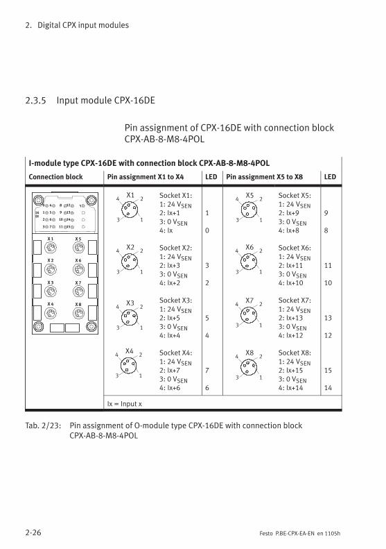
2. Digital CPX input modules
2-26 Festo P.BE-CPX-EA-EN en 1105h
2.3.5 Input module CPX-16DE
Pin assignment of CPX-16DE with connection blockCPX-AB-8-M8-4POL
I-module type CPX-16DE with connection block CPX-AB-8-M8-4POL
Connection block Pin assignment X1 to X4 LED Pin assignment X5 to X8 LED
X 1
X 2
X 3
X 4
X 5
X 6
X 7
X 8
0
1
2
3
16
DI
4
5
6
7
8
9
10
11
12
13
14
15
X34 2
3 1
X24 2
3 1
X44 2
3 1
X14 2
3 1
Socket X1:1: 24 VSEN2: Ix+13: 0 VSEN4: Ix
Socket X2:1: 24 VSEN2: Ix+33: 0 VSEN4: Ix+2
Socket X3:1: 24 VSEN2: Ix+53: 0 VSEN4: Ix+4
Socket X4:1: 24 VSEN2: Ix+73: 0 VSEN4: Ix+6
1
0
3
2
5
4
7
6
X54 2
3 1
X64 2
3 1
X74 2
3 1
X84 2
3 1
Socket X5:1: 24 VSEN2: Ix+93: 0 VSEN4: Ix+8
Socket X6:1: 24 VSEN2: Ix+113: 0 VSEN4: Ix+10
Socket X7:1: 24 VSEN2: Ix+133: 0 VSEN4: Ix+12
Socket X8:1: 24 VSEN2: Ix+153: 0 VSEN4: Ix+14
9
8
11
10
13
12
15
14
Ix = Input x
Tab. 2/23: Pin assignment of O-module type CPX-16DE with connection blockCPX-AB-8-M8-4POL

2. Digital CPX input modules
2-27Festo P.BE-CPX-EA-EN en 1105h
Pin assignment of CPX-16DE with connection blockCPX-AB-8-KL-4POL
I-module type CPX-16DE with connection block CPX-AB-8-KL-4POL
Connection block Pin assignment X1 to X4 LED Pin assignment X5 to X8 LED
X1
X2
X3
X4
X5
X6
X7
X8
.0
.1
.2
.3
.0
.1
.2
.3
.0
.1
.2
.3
.0
.1
.2
.3
0
1
2
3
16
DI
4
5
6
7
8
9
10
11
12
13
14
15
X1
X2
X3
X4
.0
.1
.2
.3
.0
.1
.2
.3
.0
.1
.2
.3
.0
.1
.2
.3
X1.0: Ix+8X1.1: 24 VSENX1.2: IxX1.3: FE
X2.0: Ix+9X2.1: 24 VSENX2.2: Ix+1X2.3: FE
X3.0: Ix+10X3.1: 24 VSENX3.2: Ix+2X3.3: FE
X4.0: Ix+11X4.1: 24 VSENX4.2: Ix+3X4.3: FE
8
0
9
1
10
2
11
3
X5
X6
X7
X8
.0
.1
.2
.3
.0
.1
.2
.3
.0
.1
.2
.3
.0
.1
.2
.3
X5.0: Ix+12X5.1: 0 VSENX5.2: Ix+4X5.3: FE
X6.0: Ix+13X6.1: 0 VSENX6.2: Ix+5X6.3: FE
X7.0: Ix+14X7.1: 0 VSENX7.2: Ix+6X7.3: FE
X8.0: Ix+15X8.1: 0 VSENX8.2: Ix+7X8.3: FE
12
4
13
5
14
6
15
7
Ix = Input xFE = Functional earth
Tab. 2/24: Pin assignment of I-module type CPX-16DE with connection blockCPX-AB-8-KL-4POL

2. Digital CPX input modules
2-28 Festo P.BE-CPX-EA-EN en 1105h
Pin assignment of CPX-16DE with connection blockCPX-AB-1-SUB-BU-25POL
I-module type CPX-16DE with connection block CPX-AB-1-SUB-BU-25POL
Connection block Pin assignment LED Pin assignment LED
0
1
2
3
16
DI
4
5
6
7
8
9
10
11
12
13
14
15
1
2
3
4
5
6
7
8
9
10
11
12
13
14
15
16
17
18
19
20
21
22
23
24
25
1: Ix2: Ix+13: Ix+24: Ix+35: Ix+96: 24 VSEN7: Ix+118: 24 VSEN9: Ix+810: Ix+1011: 24 VSEN12: 24 VSEN13: FE
01239
11
810
14: Ix+415: Ix+516: Ix+617: Ix+718: Ix+1219: Ix+1320: Ix+1421: Ix+1522: 0 VSEN23: 0 VSEN24: 0 VSEN25: FEHousing: FE
456712131415
Ix = Input xFE = Functional earth
Tab. 2/25: Pin assignment of I-module type CPX-16DE with connection blockCPX-AB-1-SUB-BU-25POL

2. Digital CPX input modules
2-29Festo P.BE-CPX-EA-EN en 1105h
2.3.6 Input module CPX-M-16DE-D with channel diagnosis
Pin assignment of CPX-M-16DE-D with connectionblock CPX-M-8-M12x2-5POL
I-module type CPX-M-16DE-D with connection block CPX-AB-8-M12x2-5POL
Connection block Pin assignment X1, X2, X3, X4 LED Pin assignment X5, X6, X7, X8 LED
2
3
1
5
4 X2
2
3
1
5
4
2
3
1
5
4
2
3
1
5
4 X4
X3
X1
Socket X1:1: 24 VSENx2: Ix+13: 0 VSENx4: Ix5: FE1)
Socket X2:1: 24 VSENx+22: Ix+33: 0 VSENx+24: Ix+25: FE1)
Socket X3:1: 24 VSENx+42: Ix+53: 0 VSENx+44: Ix+45: FE1)
Socket X4:1: 24 VSENx+62: Ix+73: 0 VSENx+64: Ix+65: FE1)
1
0
3
2
5
4
7
6
2
3
1
5
4
2
3
1
5
4
2
3
1
5
4
X5
2
3
1
5
4
X6
X7
X8
Socket X5:1: 24 VSENx+82: Ix+93: 0 VSENx+84: Ix+85: FE1)
Socket X6:1: 24 VSENx+102: Ix+113: 0 VSENx+104: Ix+105: FE1)
Socket X71: 24 VSENx+122: Ix+133: 0 VSENx+124: Ix+125: FE1)
Socket X8:1: 24 VSENx+142: Ix+153: 0 VSENx+144: Ix+145: FE1)
9
8
11
10
13
12
15
14
Ix = Input xFE = Functional earth1) In CPX-M-8-M12x2-5POL the metal thread is connected to FE
Tab. 2/26: Pin assignment of I-module type CPX-16DE-D with connection blockCPX-M-8-M12x2-5POL
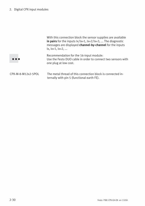
2. Digital CPX input modules
2-30 Festo P.BE-CPX-EA-EN en 1105h
With this connection block the sensor supplies are availablein pairs for the inputs Ix/Ix+1, Ix+2/Ix+3, ... The diagnosticmessages are displayed channel-by-channel for the inputsIx, Ix+1, Ix+2, ...
Recommendation for the 16-input module:Use the Festo DUO cable in order to connect two sensors withone plug at low cost.
CPX-M-8-M12x2-5POL The metal thread of this connection block is connected in-ternally with pin 5 (functional earth FE).

2. Digital CPX input modules
2-31Festo P.BE-CPX-EA-EN en 1105h
2.3.7 Input module CPX-L-16DE-16-KL-3POL
CPX-L modules do not have any exchangeable connectionblocks.
NoteWhen using 2-wire sensors the residual current at “log. 0”must be smaller than the standard value as per IEC61131-2type 1. At VIx, Ix+1,… < 5 V: Iresidual < 500 µA.
Pin assignment CPX-L-16DE-…
I-module type CPX-L-16DE-16-KL-3POL
Connection block Pin assignment X1 to X8 Pin assignment X9 to X16
X1.0: 24 VSENX1.1: IxX1.2: 0 VSENX2.0: 24 VSENX2.1: Ix+1X2.2: 0 VSENX3.0: 24 VSENX3.1: Ix+2X3.2: 0 VSENX4.0: 24 VSENX4.1: Ix+3X4.2: 0 VSENX5.0: 24 VSENX5.1: Ix+4X5.2: 0 VSENX6.0: 24 VSENX6.1: Ix+5X6.2: 0 VSENX7.0: 24 VSENX7.1: Ix+6X7.2: 0 VSENX8.0: 24 VSENX8.1: Ix+7X8.2: 0 VSEN
X9.0: 24 VSENX9.1: Ix+8X9.2: 0 VSENX10.0: 24 VSENX10.1: Ix+9X10.2: 0 VSENX11.0: 24 VSENX11.1: Ix+10X11.2: 0 VSENX12.0: 24 VSENX12.1: Ix+11X12.2: 0 VSENX13.0: 24 VSENX13.1: Ix+12X13.2: 0 VSENX14.0: 24 VSENX14.1: Ix+13X14.2: 0 VSENX15.0: 24 VSENX15.1: Ix+14X15.2: 0 VSENX16.0: 24 VSENX16.1: Ix+15X16.2: 0 VSEN
Ix = Input x
Tab. 2/27: Pin assignment of I-module type CPX-L-16DE-…
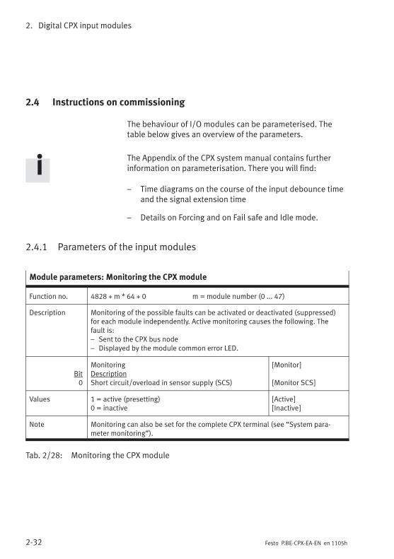
2. Digital CPX input modules
2-32 Festo P.BE-CPX-EA-EN en 1105h
2.4 Instructions on commissioning
The behaviour of I/O modules can be parameterised. Thetable below gives an overview of the parameters.
The Appendix of the CPX system manual contains furtherinformation on parameterisation. There you will find:
– Time diagrams on the course of the input debounce timeand the signal extension time
– Details on Forcing and on Fail safe and Idle mode.
2.4.1 Parameters of the input modules
Module parameters: Monitoring the CPX module
Function no. 4828 + m * 64 + 0 m = module number (0 ... 47)
Description Monitoring of the possible faults can be activated or deactivated (suppressed)for each module independently. Active monitoring causes the following. Thefault is:– Sent to the CPX bus node– Displayed by the module common error LED.
Bit0
MonitoringDescriptionShort circuit/overload in sensor supply (SCS)
[Monitor]
[Monitor SCS]
Values 1 = active (presetting)0 = inactive
[Active][Inactive]
Note Monitoring can also be set for the complete CPX terminal (see “System para-meter monitoring”).
Tab. 2/28: Monitoring the CPX module

2. Digital CPX input modules
2-33Festo P.BE-CPX-EA-EN en 1105h
Module parameters: Behaviour after short circuit/overload
Function no. 4828 + m * 64 + 1 m = module number (0 ... 47)
Description Determines after a short circuit in the sensor supply whether the power is toremain switched off or whether it is to be switched on again automatically.
Bit0
Behaviour after short circuit/overloadDescriptionShort circuit/overload in sensor supply (SCS)
[Behaviour after]
[Behaviour after SCS]
Values 0 = VSEN remains switched off1 = VSEN switch on again (presetting)
[Leave switched off ][Resume]
Note With the setting “VSEN/OUT remains switched off,” Power Off/On is necessary torestore the power. Check which setting is necessary for reliable operation of yoursystem.This parameter also applies to the entire module for modules CPX-8DE-D andCPX-M-16DE-D.Detailed description under Diagnosis, Tab. 2/34.
Tab. 2/29: Behaviour after short circuit/overload
Module parameters: Input debounce time
Function no. 4828 + m * 64 + 1 m = module number (0 ... 47)
Description Determines when a change of edge of the sensor signal on this module is to beaccepted as a logical input signal.
Bit Bit 4, 5
ValuesBit 5 4
0 00 11 01 1
Input debounce timeDescription0.1 ms3 ms (presetting)10 ms20 ms
[Debounce time]
Note Input debounce times are specified in order to eliminate interfering changes ofsignal edge during switching procedures (bouncing of the input signal). Thissetting applies to all inputs of the module.Further information on this parameter can be found in the CPX system manual.
Tab. 2/30: Input debounce time
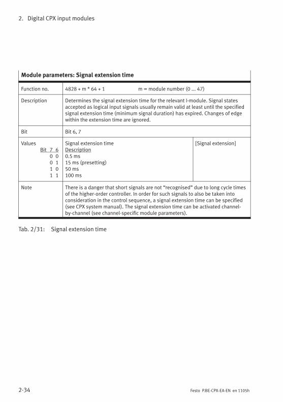
2. Digital CPX input modules
2-34 Festo P.BE-CPX-EA-EN en 1105h
Module parameters: Signal extension time
Function no. 4828 + m * 64 + 1 m = module number (0 ... 47)
Description Determines the signal extension time for the relevant I-module. Signal statesaccepted as logical input signals usually remain valid at least until the specifiedsignal extension time (minimum signal duration) has expired. Changes of edgewithin the extension time are ignored.
Bit Bit 6, 7
ValuesBit 7 6
0 00 11 01 1
Signal extension timeDescription0.5 ms15 ms (presetting)50 ms100 ms
[Signal extension]
Note There is a danger that short signals are not “recognised” due to long cycle timesof the higher-order controller. In order for such signals to also be taken intoconsideration in the control sequence, a signal extension time can be specified(see CPX system manual). The signal extension time can be activated channel-by-channel (see channel-specific module parameters).
Tab. 2/31: Signal extension time

2. Digital CPX input modules
2-35Festo P.BE-CPX-EA-EN en 1105h
Module parameters: Signal extension channel x
Function no. 4828 + m * 64 + 6 m = module number (0 ... 47)4828 + m * 64 + 7 (additionally for CPX-16DE, channel 8 ... 15)
Description Determines whether the signal extension for the relevant I-channel is to beenabled or blocked.
Bit Bit 0 ... 7 (channel 0 ... 7)Bit 0 ... 7 (channel 8 ... 15) (for CPX-16DE channel 8 ... 15
with function no. 4828 + m * 64 + 7)
Values Signal extension input channel ...0 = blocked (presetting)1 = enabled
[Signal extension Inp Ch ...][Disabled][Enabled]
Note The signal extension time can be specified separately for each module(see function no. 4828 + m * 64 +1, bit 6, 7).
Tab. 2/32: Signal extension channel x (channel-specific)
Module parameters: Force channel x
Function no. Access to these module parameters is enabled via protocol-specific functions(see the manual for the bus node).
Description Force mode of inputs channel x: blocked (presetting)Force state
Force state of inputs channel x: Set signalReset signal (presetting)
Note The Force function enables the manipulation of signal states detached fromactual operating states (also refer to the CPX system manual).
Tab. 2/33: Force channel x (channel-specific)

2. Digital CPX input modules
2-36 Festo P.BE-CPX-EA-EN en 1105h
2.5 Diagnosis
Specific faults of the input modules are registered orsuppressed depending on the module parameterisation.
The faults are indicated locally via the Error LED and, ifnecessary, they can be evaluated with the handheld (MMI).
The faults are sent to the bus node (depending on moduleparameterisation), where they can be evaluated according tothe fieldbus protocol used.
2.5.1 Error messages of the input modules
An input module can register the following standard faults:
Error number Description Error handling
2 Fault short circuit/overloadShort circuit/overload in sensorsupply (VEL/SEN).
1. Eliminate short circuit/overload or checkconnected sensors
2. Depending on parameterisation“Behaviour after short circuit/overloadin sensor supply (SCS)” (see Tab. 2/29):• Setting “VSEN switch on again”:
Power supply for sensors will beswitched on again automaticallywhen the short circuit is eliminated.
• Setting “VSEN remains switched off”:– Power Off/On necessaryor– modify parameter “Short circuit/overload in sensor supply (SCS)” to“VSEN switch on again”.
Tab. 2/34: Error messages of the input modules

2. Digital CPX input modules
2-37Festo P.BE-CPX-EA-EN en 1105h
NoteWhen using the input modules please note that the sensorsupplies are switched off differently in the event of a shortcircuit depending on the module and connection blockused. Tab. 2/35 provides an overview of this.
Providing it is not programmed otherwise, the sensorsupply voltage will be switched on again automaticallywhen the short circuit is eliminated.
CPX-4DECPX-8DECPX-8NDECPX-16DECPX-L-16DE
CPX-8DE-D(except with theconnection blocksdesignated in the nextcolumn)
CPX-8DE-Dwith connection blocks:– AB-4-M12x2-5POL(-R)– AB-4-HARX2-4POL– CPX-M-4-M12x2-5POL
CPX-M-16DE-D
The diagnosticmessages aredisplayed togetherfor all inputs.
The diagnosticmessages are displayedchannel-by-channel foreach input. Forexceptions refer to thenext column!
The diagnostic messagesare only displayed forinputs Ix, Ix+2, Ix+4 andIx+6.Inputs Ix+1, Ix+3, Ix+5 andIx+7 do not generate anydiagnostic messages.
The diagnosticmessages aredisplayedchannel-by-channelfor each input.
If there is a shortcircuit, all sensorsupplies will beswitched offtogether.
If there is a short circuit,the sensor supplies willbe switched offchannel-by-channel.
The sensor supplies are grouped together in pairson these connection blocks.If there is a short circuit, the sensor supplies will beswitched off in pairs: Ix and Ix+1, Ix+2 and Ix+3,Ix+4 and Ix+5, …
Tab. 2/35: Different behaviour of the input modules in the event of a short circuit

2. Digital CPX input modules
2-38 Festo P.BE-CPX-EA-EN en 1105h
2.5.2 LED display
Various LEDs are situated under the transparent cover of thedevice for diagnosing the input modules.
0
1
2
3
8
DI
4
5
6
7
CPX-8DE CPX-8DE-D
0
1
2
3
8
DI-D
4
5
6
7
0
1
2
3
4
DI
CPX-4DE
1 23 11 3 3
0
1
2
3
8
NDI
4
5
6
7
CPX-8NDE
1 3
0
1
2
3
16
DI
4
5
6
7
CPX-16DE
1 3
8
9
10
11
12
13
14
15
1 Status LEDs (green): for assignment tothe inputs see the pin assignment ofthe module
2 Channel-related error LEDs (red)
3 Error LED (red)
4 Shared LEDs for status of the input(green) or channel-related error (red)
Fig. 2/1: LED display of the input modules (part 1)

2. Digital CPX input modules
2-39Festo P.BE-CPX-EA-EN en 1105h
The LEDs are located directly next to the ports for channel-oriented diagnostics of the CPX metal and CPX-L inputmodules.
21
CPX-M-16DE-D CPX-L-16DE-16-KL-3POL
33 2
1 Shared LEDs for status of the input(green) or channel-related error (red)
2 Error LED (red): Module fault
3 Status LEDs (green) for the inputs
Fig. 2/2: LED display of the input modules (part 2, CPX metal and CPX-L)
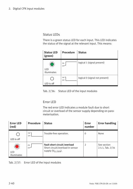
2. Digital CPX input modules
2-40 Festo P.BE-CPX-EA-EN en 1105h
Status LEDs
There is a green status LED for each input. This LED indicatesthe status of the signal at the relevant input. This means:
Status LED(green)
Procedure Status
LEDilluminates
ON
OFF
logical 1 (signal present)
LED is off
ON
OFF
logical 0 (signal not present)
Tab. 2/36: Status LED of the input modules
Error LED
The red error LED indicates a module fault due to shortcircuit or overload of the sensor supply depending on para-meterisation.
Error LED(red)
Procedure Status Errornumber
Error handling
LED is off
ON
OFF
Trouble-free operation. 0 None
LEDilluminates
ON
OFF
Fault short circuit/overloadShort circuit/overload in sensorsupply (VEL/SEN).
2 See section2.5.1, Tab. 2/34
Tab. 2/37: Error LED of the input modules

2. Digital CPX input modules
2-41Festo P.BE-CPX-EA-EN en 1105h
Channel-related error LEDs (only CPX-8DE-D andCPX-M-16DE-D)
Module CPX-8DE-D has a separate red error LED for eachinput; module CPX-M-16DE-D has a combined green/red LEDfor status and error display. The error LEDs of the inputsindicate a fault at the input caused by short circuit oroverload irrespective of parameterisation.
Channel-related errorLED (red)
Procedure Status Errornumber
Errorhandling
LED is off
ON
OFF
Input without short circuit/over-load, trouble-free operation.
0 None
LEDilluminates
ON
OFF
Fault short circuit/overloadShort circuit/overload in sensorsupply 24 VSENx...
2 See section2.5.1, Tab. 2/34
Tab. 2/38: Channel-related error LEDs for input module CPX-8DE-D and CPX-M-16DE-D
NotePlease note that the diagnostic messages and the discon-nection of sensor supplies in input modules CPX-8DE-Dand CPX-M-16DE-D depends on the connection blockused. A detailed description can be found in Tab. 2/35.
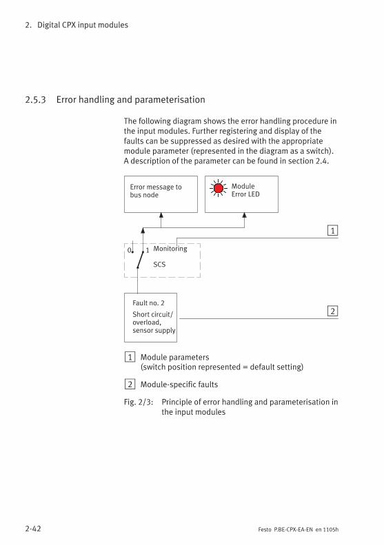
2. Digital CPX input modules
2-42 Festo P.BE-CPX-EA-EN en 1105h
2.5.3 Error handling and parameterisation
The following diagram shows the error handling procedure inthe input modules. Further registering and display of thefaults can be suppressed as desired with the appropriatemodule parameter (represented in the diagram as a switch).A description of the parameter can be found in section 2.4.
Fault no. 2
Short circuit/overload,sensor supply
Error message tobus node
Monitoring
SCS
ModuleError LED
2
1
0 1
1 Module parameters(switch position represented = default setting)
2 Module-specific faults
Fig. 2/3: Principle of error handling and parameterisation inthe input modules

Digital CPX output modules
3-1Festo P.BE-CPX-EA-EN en 1105h
Chapter 3
Type CPX-4DA
CPX-8DA
CPX-8DA-H
Digital CPX output modules

3. Digital CPX output modules
3-2 Festo P.BE-CPX-EA-EN en 1105h
Contents
3. Digital CPX output modules 3-1. . . . . . . . . . . . . . . . . . . . . . . . . . . . . . . . . . . . . .
3.1 Function of the output modules 3-3. . . . . . . . . . . . . . . . . . . . . . . . . . . . . . . . . . .
3.2 Assembly 3-3. . . . . . . . . . . . . . . . . . . . . . . . . . . . . . . . . . . . . . . . . . . . . . . . . . . . .
3.3 Installation 3-4. . . . . . . . . . . . . . . . . . . . . . . . . . . . . . . . . . . . . . . . . . . . . . . . . . . .
3.3.1 Output module CPX-4DA 3-5. . . . . . . . . . . . . . . . . . . . . . . . . . . . . . . . . .
3.3.2 Output module CPX-8DA 3-11. . . . . . . . . . . . . . . . . . . . . . . . . . . . . . . . . .
3.3.3 High-current output module CPX-8DA-H 3-17. . . . . . . . . . . . . . . . . . . . .
3.4 Instructions on commissioning 3-22. . . . . . . . . . . . . . . . . . . . . . . . . . . . . . . . . . . .
3.4.1 Parameters of the output modules 3-22. . . . . . . . . . . . . . . . . . . . . . . . .
3.5 Diagnosis 3-25. . . . . . . . . . . . . . . . . . . . . . . . . . . . . . . . . . . . . . . . . . . . . . . . . . . . .
3.5.1 Error messages of the output modules 3-26. . . . . . . . . . . . . . . . . . . . . .
3.5.2 LED display 3-27. . . . . . . . . . . . . . . . . . . . . . . . . . . . . . . . . . . . . . . . . . . .
3.5.3 Error handling and parameterisation 3-29. . . . . . . . . . . . . . . . . . . . . . . .
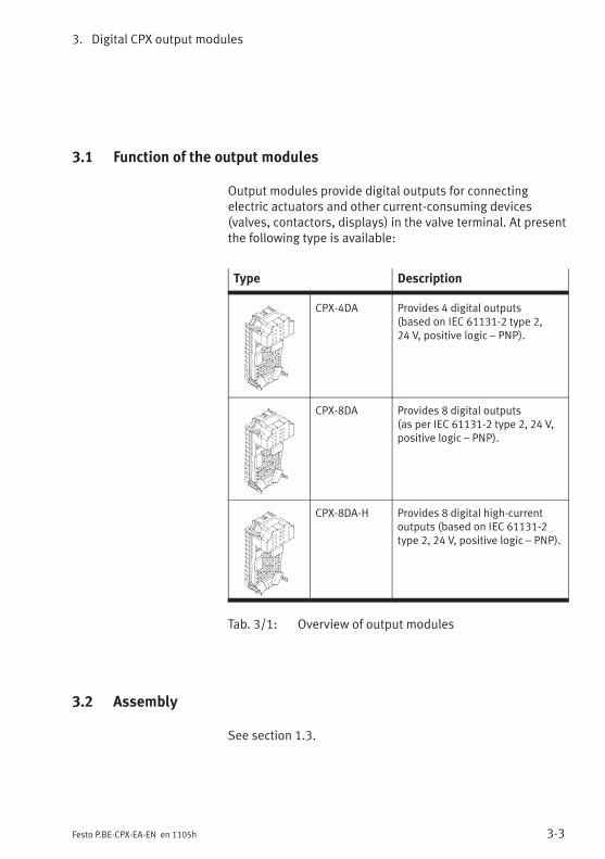
3. Digital CPX output modules
3-3Festo P.BE-CPX-EA-EN en 1105h
3.1 Function of the output modules
Output modules provide digital outputs for connectingelectric actuators and other current-consuming devices(valves, contactors, displays) in the valve terminal. At presentthe following type is available:
Type Description
CPX-4DA Provides 4 digital outputs(based on IEC 61131-2 type 2,24 V, positive logic – PNP).
CPX-8DA Provides 8 digital outputs(as per IEC 61131-2 type 2, 24 V,positive logic – PNP).
CPX-8DA-H Provides 8 digital high-currentoutputs (based on IEC 61131-2type 2, 24 V, positive logic – PNP).
Tab. 3/1: Overview of output modules
3.2 Assembly
See section 1.3.
3. Digital CPX output modules
3-4 Festo P.BE-CPX-EA-EN en 1105h
3.3 Installation
WarningUncontrolled movements of the connected actuators anduncontrolled movements of loose tubing can cause injuryto human beings or damage to property.
Before carrying out installation and maintenance work,switch off the following:
– Compressed air supply
– The operating and load voltage supplies.
In the following sections you will find the pin assignments ofthe output modules for the different connection blocks.
Instructions on connecting the cables and plugs to the con-nection blocks can be found in section 1.2.3.
Power supply
The 24 V supply for the electronics of the output modules isprovided via the operating voltage supply for the electronics/sensors (VEL/SEN).
The 24 V supply for the outputs is provided via the loadvoltage outputs of the CPX terminal (VOUT).
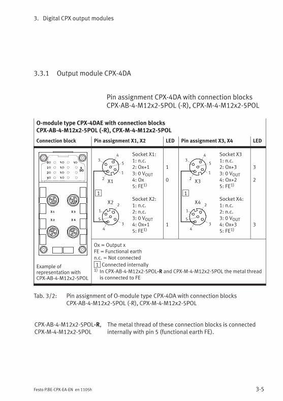
3. Digital CPX output modules
3-5Festo P.BE-CPX-EA-EN en 1105h
3.3.1 Output module CPX-4DA
Pin assignment CPX-4DA with connection blocksCPX-AB-4-M12x2-5POL (-R), CPX-M-4-M12x2-5POL
O-module type CPX-4DAE with connection blocksCPX-AB-4-M12x2-5POL (-R), CPX-M-4-M12x2-5POL
Connection block Pin assignment X1, X2 LED Pin assignment X3, X4 LED
0
1
2
3
4DO
Example ofrepresentation withCPX-AB-4-M12x2-5POL
1
2
2
3
3
1
1
5
5
4
4
X1
X2
Socket X1:1: n.c.2: Ox+13: 0 VOUT4: Ox5: FE1)
Socket X2:1: n.c.2: n.c.3: 0 VOUT4: Ox+15: FE1)
1
0
1
1
2
2
3
3
1
1
5
5
4
4
X3
X4
Socket X31: n.c.2: Ox+33: 0 VOUT4: Ox+25: FE1)
Socket X4:1: n.c.2: n.c.3: 0 VOUT4: Ox+35: FE1)
3
2
3
Ox = Output xFE = Functional earthn.c. = Not connected
1 Connected internally1) In CPX-AB-4-M12x2-5POL-R and CPX-M-4-M12x2-5POL the metal thread
is connected to FE
Tab. 3/2: Pin assignment of O-module type CPX-4DA with connection blocksCPX-AB-4-M12x2-5POL (-R), CPX-M-4-M12x2-5POL
CPX-AB-4-M12x2-5POL-R,CPX-M-4-M12x2-5POL
The metal thread of these connection blocks is connectedinternally with pin 5 (functional earth FE).

3. Digital CPX output modules
3-6 Festo P.BE-CPX-EA-EN en 1105h
Pin assignment CPX-4DA with connection blockCPX-AB-8-M8-3POL
NoteSockets X1 to X8 on the connection block are markedaccordingly. The numbering of the sockets does notcorrespond to the output addresses.
O-module type CPX-4DA with connection block CPX-AB-8-M8-3POL
Connection block Pin assignment X1 to X4 LED Pin assignment X5 to X8 LED
0
1
2
3
4DO
X 1
X 2
X 3
X 4
X 5
X 6
X 7
X 8
1
X14 1
3
X24 1
3
X34 1
3
X44 1
3
Socket X1:1: n.c.3: 0 VOUT4: Ox
Socket X2:1: n.c.3: 0 VOUT4: Ox+1
Socket X3:1: n.c.3: 0 VOUT4: Ox+1
Socket X4:1: n.c.3: 0 VOUT4: n.c.
0
1
1
1
X54 1
3
X64 1
3
X74 1
3
X84 1
3
Socket X5:1: n.c.3: 0 VOUT4: Ox+2
Socket X6:1: n.c.3: 0 VOUT4: Ox+3
Socket X7:1: n.c.3: 0 VOUT4: Ox+3
Socket X8:1: n.c.3: 0 VOUT4: n.c.
2
3
3
Ox = Output xFE = Functional earthn.c. = Not connected
1 Connected internally
Tab. 3/3: Pin assignment of O-module type CPX-4DA with connection blockCPX-AB-8-M8-3POL
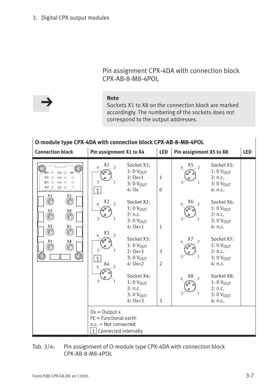
3. Digital CPX output modules
3-7Festo P.BE-CPX-EA-EN en 1105h
Pin assignment CPX-4DA with connection blockCPX-AB-8-M8-4POL
NoteSockets X1 to X8 on the connection block are markedaccordingly. The numbering of the sockets does notcorrespond to the output addresses.
O-module type CPX-4DA with connection block CPX-AB-8-M8-4POL
Connection block Pin assignment X1 to X4 LED Pin assignment X5 to X8 LED
X34 2
3 1
X24 2
3 1
X44 2
3 1
X14 2
3 1
1
1
Socket X1:1: 0 VOUT2: Ox+13: 0 VOUT4: Ox
Socket X2:1: 0 VOUT2: n.c.3: 0 VOUT4: Ox+1
Socket X3:1: 0 VOUT2: Ox+33: 0 VOUT4: Ox+2
Socket X4:1: 0 VOUT2: n.c.3: 0 VOUT4: Ox+3
1
0
1
3
2
3
X54 2
3 1
X64 2
3 1
X74 2
3 1
X84 2
3 1
Socket X5:1: 0 VOUT2: n.c.3: 0 VOUT4: n.c.
Socket X6:1: 0 VOUT2: n.c.3: 0 VOUT4: n.c.
Socket X7:1: 0 VOUT2: n.c.3: 0 VOUT4: n.c.
Socket X8:1: 0 VOUT2: n.c.3: 0 VOUT4: n.c.
Ox = Output xFE = Functional earthn.c. = Not connected
1 Connected internally
Tab. 3/4: Pin assignment of O-module type CPX-4DA with connection blockCPX-AB-8-M8-4POL
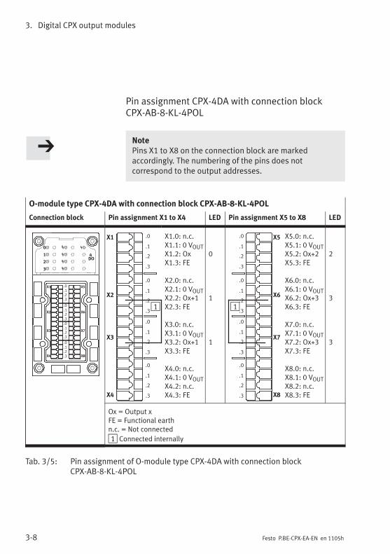
3. Digital CPX output modules
3-8 Festo P.BE-CPX-EA-EN en 1105h
Pin assignment CPX-4DA with connection blockCPX-AB-8-KL-4POL
NotePins X1 to X8 on the connection block are markedaccordingly. The numbering of the pins does notcorrespond to the output addresses.
O-module type CPX-4DA with connection block CPX-AB-8-KL-4POL
Connection block Pin assignment X1 to X4 LED Pin assignment X5 to X8 LED
0
1
2
3
4DO
X1
X2
X3
X4
X5
X6
X7
X8
.0
.1
.2
.3
.0
.1
.2
.3
.0
.1
.2
.3
.0
.1
.2
.3
X1
X2
X3
X4
.0
.1
.2
.3
.0
.1
.2
.3
.0
.1
.2
.3
.0
.1
.2
.3
1
X1.0: n.c.X1.1: 0 VOUTX1.2: OxX1.3: FE
X2.0: n.c.X2.1: 0 VOUTX2.2: Ox+1X2.3: FE
X3.0: n.c.X3.1: 0 VOUTX3.2: Ox+1X3.3: FE
X4.0: n.c.X4.1: 0 VOUTX4.2: n.c.X4.3: FE
0
1
1
X5
X6
X7
X8
.0
.1
.2
.3
.0
.1
.2
.3
.0
.1
.2
.3
.0
.1
.2
.3
1
X5.0: n.c.X5.1: 0 VOUTX5.2: Ox+2X5.3: FE
X6.0: n.c.X6.1: 0 VOUTX6.2: Ox+3X6.3: FE
X7.0: n.c.X7.1: 0 VOUTX7.2: Ox+3X7.3: FE
X8.0: n.c.X8.1: 0 VOUTX8.2: n.c.X8.3: FE
2
3
3
Ox = Output xFE = Functional earthn.c. = Not connected
1 Connected internally
Tab. 3/5: Pin assignment of O-module type CPX-4DA with connection blockCPX-AB-8-KL-4POL

3. Digital CPX output modules
3-9Festo P.BE-CPX-EA-EN en 1105h
Pin assignment of CPX-4DA with connection blockCPX-AB-1-SUB-BU-25POL
O-module type CPX-4DA with connection block CPX-AB-1-SUB-BU-25POL
Connection block Pin assignment LED Pin assignment LED
0
1
2
3
4
DO
1
2
3
4
5
6
7
8
9
10
11
12
13
14
15
16
17
18
19
20
21
22
23
24
25
1: Ox2: Ox+13: Ox+14: n.c.5: n.c.6: 0 VOUT7: n.c.8: 0 VOUT9: n.c.10: n.c.11: 0 VOUT12: 0 VOUT13: FE
011
14: Ox+215: Ox+316: Ox+317: n.c.18: n.c.19: n.c.20: n.c.21: n.c.22: 0 VOUT23: 0 VOUT24: 0 VOUT25: FEHousing: FE
233
Ox = Output xFE = Functional earth0 V = 0 V loadn.c. = Not connected
Tab. 3/6: Pin assignment of O-module type CPX-4DA with connection blockCPX-AB-1-SUB-BU-25POL

3. Digital CPX output modules
3-10 Festo P.BE-CPX-EA-EN en 1105h
Pin assignment CPX-4DA with connection blockCPX-AB-4-HARX2-4POL
O-module type CPX-4DA with connection block CPX-AB-4-HARX2-4POL
Connection block Pin assignment X1, X2 LED Pin assignment X3, X4 LED
0
1
2
3
4
DO
1
23
14
X1
X22 3
1 4
Socket X1:1: n.c.2: Ox+13: 0 VOUT4: Ox
Socket X2:1: n.c.2: n.c.3: 0 VOUT4: Ox+1
1
0
1
1
23
14
X3
X42 3
1 4
Socket X31: n.c.2: Ox+33: 0 VOUT4: Ox+2
Socket X4:1: n.c.2: n.c.3: 0 VOUT4: Ox+3
3
2
3
Ox = Output xFE = Functional earthn.c. = Not connected
1 Connected internally
Tab. 3/7: Pin assignment of O-module type CPX-4DA with connection blockCPX-AB-4-HARX2-4POL

3. Digital CPX output modules
3-11Festo P.BE-CPX-EA-EN en 1105h
3.3.2 Output module CPX-8DA
Pin assignment CPX-8DA with connection blocksCPX-AB-4-M12x2-5POL (-R), CPX-M-4-M12x2-5POL
O-module type CPX-8DA with connection blocksCPX-AB-4-M12x2-5POL (-R), CPX-M-4-M12x2-5POL
Connection block Pin assignment X1, X2 LED Pin assignment X3, X4 LED
Example ofrepresentation withCPX-AB-4-M12x2-5POL
2
2
3
3
1
1
5
5
4
4
X1
X2
Socket X1:1: n.c.2: Ox+13: 0 VOUT4: Ox5: FE1)
Socket X2:1: n.c.2: Ox+33: 0 VOUT4: Ox+25: FE1)
1
0
3
2
2
3
1
5
4
2
3
1
5
4
X3
X4
Socket X31: n.c.2: Ox+53: 0 VOUT4: Ox+45: FE1)
Socket X4:1: n.c.2: Ox+73: 0 VOUT4: Ox+65: FE1)
5
4
7
6
Ox = Output xFE = Functional earthn.c. = Not connected1) In CPX-AB-4-M12x2-5POL-R and CPX-M-4-M12x2-5POL the metal thread
is connected to FE
Tab. 3/8: Pin assignment of O-module type CPX-8DA with connection blockCPX-AB-4-M12x2-5POL (-R), CPX-M-4-M12x2-5POL
CPX-AB-4-M12x2-5POL-R,CPX-M-4-M12x2-5POL
The metal thread of these connection blocks is connectedinternally with pin 5 (functional earth FE).
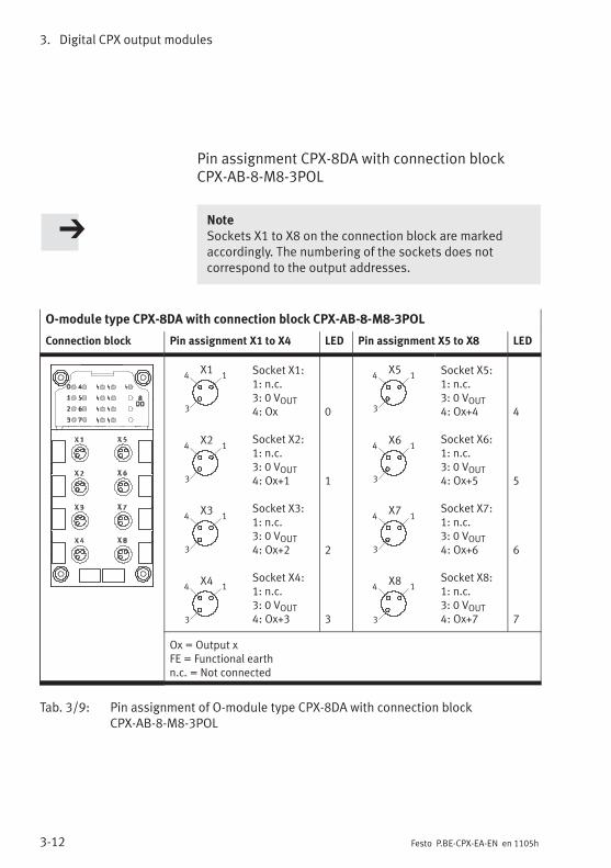
3. Digital CPX output modules
3-12 Festo P.BE-CPX-EA-EN en 1105h
Pin assignment CPX-8DA with connection blockCPX-AB-8-M8-3POL
NoteSockets X1 to X8 on the connection block are markedaccordingly. The numbering of the sockets does notcorrespond to the output addresses.
O-module type CPX-8DA with connection block CPX-AB-8-M8-3POL
Connection block Pin assignment X1 to X4 LED Pin assignment X5 to X8 LED
X14 1
3
X24 1
3
X34 1
3
X44 1
3
Socket X1:1: n.c.3: 0 VOUT4: Ox
Socket X2:1: n.c.3: 0 VOUT4: Ox+1
Socket X3:1: n.c.3: 0 VOUT4: Ox+2
Socket X4:1: n.c.3: 0 VOUT4: Ox+3
0
1
2
3
X54 1
3
X64 1
3
X74 1
3
X84 1
3
Socket X5:1: n.c.3: 0 VOUT4: Ox+4
Socket X6:1: n.c.3: 0 VOUT4: Ox+5
Socket X7:1: n.c.3: 0 VOUT4: Ox+6
Socket X8:1: n.c.3: 0 VOUT4: Ox+7
4
5
6
7
Ox = Output xFE = Functional earthn.c. = Not connected
Tab. 3/9: Pin assignment of O-module type CPX-8DA with connection blockCPX-AB-8-M8-3POL

3. Digital CPX output modules
3-13Festo P.BE-CPX-EA-EN en 1105h
Pin assignment CPX-8DA with connection blockCPX-AB-8-M8-4POL
NoteSockets X1 to X8 on the connection block are markedaccordingly. The numbering of the sockets does notcorrespond to the output addresses.
O-module type CPX-8DA with connection block CPX-AB-8-M8-4POL
Connection block Pin assignment X1 to X4 LED Pin assignment X5 to X8 LED
X34 2
3 1
X24 2
3 1
X44 2
3 1
X14 2
3 1
Socket X1:1: 0 VOUT2: Ox+13: 0 VOUT4: Ox
Socket X2:1: 0 VOUT2: Ox+33: 0 VOUT4: Ox+2
Socket X3:1: 0 VOUT2: Ox+53: 0 VOUT4: Ox+4
Socket X4:1: 0 VOUT2: Ox+73: 0 VOUT4: Ox+6
1
0
3
2
5
4
7
6
X54 2
3 1
X64 2
3 1
X74 2
3 1
X84 2
3 1
Socket X5:1: 0 VOUT2: n.c.3: 0 VOUT4: n.c.
Socket X6:1: 0 VOUT2: n.c.3: 0 VOUT4: n.c.
Socket X7:1: 0 VOUT2: n.c.3: 0 VOUT4: n.c.
Socket X8:1: 0 VOUT2: n.c.3: 0 VOUT4: n.c.
Ox = Output xFE = Functional earthn.c. = Not connected
Tab. 3/10: Pin assignment of O-module type CPX-8DA with connection blockCPX-AB-8-M8-4POL

3. Digital CPX output modules
3-14 Festo P.BE-CPX-EA-EN en 1105h
Pin assignment CPX-8DA with connection blockCPX-AB-8-KL-4POL
NotePins X1 to X8 on the connection block are markedaccordingly. The numbering of the pins does notcorrespond to the output addresses.
O-module type CPX-8DA with connection block CPX-AB-8-KL-4POL
Connection block Pin assignment X1 to X4 LED Pin assignment X5 to X8 LED
X1
X2
X3
X4
.0
.1
.2
.3
.0
.1
.2
.3
.0
.1
.2
.3
.0
.1
.2
.3
X1.0: n.c.X1.1: 0 VOUTX1.2: OxX1.3: FE
X2.0: n.c.X2.1: 0 VOUTX2.2: Ox+1X2.3: FE
X3.0: n.c.X3.1: 0 VOUTX3.2: Ox+2X3.3: FE
X4.0: n.c.X4.1: 0 VOUTX4.2: Ox+3X4.3: FE
0
1
2
3
X5
X6
X7
X8
.0
.1
.2
.3
.0
.1
.2
.3
.0
.1
.2
.3
.0
.1
.2
.3
X5.0: n.c.X5.1: 0 VOUTX5.2: Ox+4X5.3: FE
X6.0: n.c.X6.1: 0 VOUTX6.2: Ox+5X6.3: FE
X7.0: n.c.X7.1: 0 VOUTX7.2: Ox+6X7.3: FE
X8.0: n.c.X8.1: 0 VOUTX8.2: Ox+7X8.3: FE
4
5
6
7
Ox = Output xFE = Functional earthn.c. = Not connected
Tab. 3/11: Pin assignment of O-module type CPX-8DA with connection blockCPX-AB-8-KL-4POL

3. Digital CPX output modules
3-15Festo P.BE-CPX-EA-EN en 1105h
Pin assignment CPX-8DA with connection blockCPX-AB-1-SUB-BU-25POL
O-module type CPX-8DA with connection block CPX-AB-1-SUB-BU-25POL
Connection block Pin assignment LED Pin assignment LED
1
2
3
4
5
6
7
8
9
10
11
12
13
14
15
16
17
18
19
20
21
22
23
24
25
1: Ox2: Ox+13: Ox+24: Ox+35: n.c.6: 0 VOUT7: n.c.8: 0 VOUT9: n.c.10: n.c.11: 0 VOUT12: 0 VOUT13: FE
0123
14: Ox+415: Ox+516: Ox+617: Ox+718: n.c.19: n.c.20: n.c.21: n.c.22: 0 VOUT23: 0 VOUT24: 0 VOUT25: FEHousing: FE
4567
Ox = Output xFE = Functional earth0 V = 0 V loadn.c. = Not connected
Tab. 3/12: Pin assignment of O-module type CPX-8DA with connection blockCPX-AB-1-SUB-BU-25POL

3. Digital CPX output modules
3-16 Festo P.BE-CPX-EA-EN en 1105h
Pin assignment CPX-8DA with connection blockCPX-AB-4-HARX2-4POL
O-module type CPX-8DA with connection block CPX-AB-4-HARX2-4POL
Connection block Pin assignment X1, X2 LED Pin assignment X3, X4 LED
23
14
X1
X22 3
1 4
Socket X1:1: n.c.2: Ox+13: 0 VOUT4: Ox
Socket X2:1: n.c.2: Ox+33: 0 VOUT4: Ox+2
1
0
3
2
23
14
X3
X42 3
1 4
Socket X31: n.c.2: Ox+53: 0 VOUT4: Ox+4
Socket X4:1: n.c.2: Ox+73: 0 VOUT4: Ox+6
5
4
7
6
Ox = Output xFE = Functional earthn.c. = Not connected
Tab. 3/13: Pin assignment of O-module type CPX-8DA with connection blockCPX-AB-4-HARX2-4POL
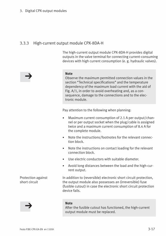
3. Digital CPX output modules
3-17Festo P.BE-CPX-EA-EN en 1105h
3.3.3 High-current output module CPX-8DA-H
The high-current output module CPX-8DA-H provides digitaloutputs in the valve terminal for connecting current-consumingdevices with high current consumption (e. g. hydraulic valves).
NoteObserve the maximum permitted connection values in thesection “Technical specifications” and the temperaturedependency of the maximum load current with the aid ofFig. A/1, in order to avoid overheating and, as a con-sequence, damage to the connections and to the elec-tronic module.
Pay attention to the following when planning:
• Maximum current consumption of 2.1 A per output/chan-nel or per output socket when the plug/cable is assignedtwice and a maximum current consumption of 8.4 A forthe complete module.
• Note the instructions/footnotes for the relevant connec-tion block.
• Note the instructions on contact loading for the relevantconnection block.
• Use electric conductors with suitable diameter.
• Avoid long distances between the load and the high-cur-rent output.
Protection against In addition to (reversible) electronic short circuit protection,short circuit the output module also possesses an (irreversible) fuse
(fusible cutout) in case the electronic short circuit protectiondevice fails.
NoteAfter the fusible cutout has functioned, the high-currentoutput module must be replaced.
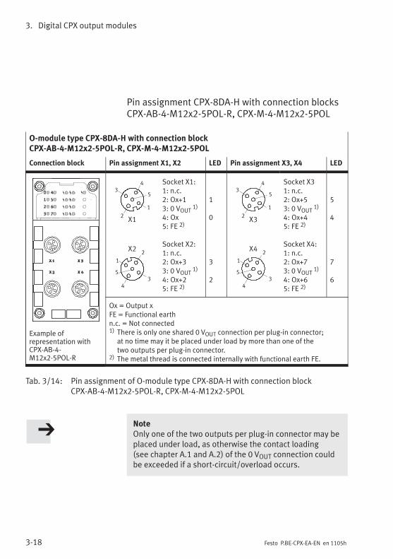
3. Digital CPX output modules
3-18 Festo P.BE-CPX-EA-EN en 1105h
Pin assignment CPX-8DA-H with connection blocksCPX-AB-4-M12x2-5POL-R, CPX-M-4-M12x2-5POL
O-module type CPX-8DA-H with connection blockCPX-AB-4-M12x2-5POL-R, CPX-M-4-M12x2-5POL
Connection block Pin assignment X1, X2 LED Pin assignment X3, X4 LED
Example ofrepresentation withCPX-AB-4-M12x2-5POL-R
2
2
3
3
1
1
5
5
4
4
X1
X2
Socket X1:1: n.c.2: Ox+13: 0 VOUT 1)
4: Ox5: FE 2)
Socket X2:1: n.c.2: Ox+33: 0 VOUT 1)
4: Ox+25: FE 2)
1
0
3
2
2
3
1
5
4
2
3
1
5
4
X3
X4
Socket X31: n.c.2: Ox+53: 0 VOUT 1)
4: Ox+45: FE 2)
Socket X4:1: n.c.2: Ox+73: 0 VOUT 1)
4: Ox+65: FE 2)
5
4
7
6
Ox = Output xFE = Functional earthn.c. = Not connected1) There is only one shared 0 VOUT connection per plug-in connector;
at no time may it be placed under load by more than one of thetwo outputs per plug-in connector.
2) The metal thread is connected internally with functional earth FE.
Tab. 3/14: Pin assignment of O-module type CPX-8DA-H with connection blockCPX-AB-4-M12x2-5POL-R, CPX-M-4-M12x2-5POL
NoteOnly one of the two outputs per plug-in connector may beplaced under load, as otherwise the contact loading(see chapter A.1 and A.2) of the 0 VOUT connection couldbe exceeded if a short-circuit/overload occurs.

3. Digital CPX output modules
3-19Festo P.BE-CPX-EA-EN en 1105h
Pin assignment CPX-8DA-H with connection blockCPX-AB-8-M8-4POL
NoteSockets X1 to X8 on the connection block are markedaccordingly. The numbering of the sockets does notcorrespond to the output addresses.
O-module type CPX-8DA-H with connection block CPX-AB-8-M8-4POL
Connection block Pin assignment X1 to X4 LED Pin assignment X5 to X8 LED
X34 2
3 1
X24 2
3 1
X44 2
3 1
X14 2
3 1
Socket X1:1: 0 VOUT 1)
2: Ox+13: 0 VOUT 1)
4: Ox
Socket X2:1: 0 VOUT 1)
2: Ox+33: 0 VOUT 1)
4: Ox+2
Socket X3:1: 0 VOUT 1)
2: Ox+53: 0 VOUT 1)
4: Ox+4
Socket X4:1: 0 VOUT 1)
2: Ox+73: 0 VOUT 1)
4: Ox+6
1
0
3
2
5
4
7
6
X54 2
3 1
X64 2
3 1
X74 2
3 1
X84 2
3 1
Socket X5:1: 0 VOUT 1)
2: n.c.3: 0 VOUT 1)
4: n.c.
Socket X6:1: 0 VOUT 1)
2: n.c.3: 0 VOUT 1)
4: n.c.
Socket X7:1: 0 VOUT 1)
2: n.c.3: 0 VOUT 1)
4: n.c.
Socket X8:1: 0 VOUT 1)
2: n.c.3: 0 VOUT 1)
4: n.c.
Ox = Output xFE = Functional earthn.c. = Not connected1) The relevant 0 VOUT connection must be used for each channel
(contact loading see chapter A.1 and A.2)
Tab. 3/15: Pin assignment of O-module type CPX-8DA-H with connection blockCPX-AB-8-M8-4POL
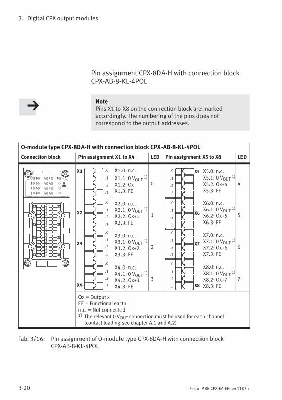
3. Digital CPX output modules
3-20 Festo P.BE-CPX-EA-EN en 1105h
Pin assignment CPX-8DA-H with connection blockCPX-AB-8-KL-4POL
NotePins X1 to X8 on the connection block are markedaccordingly. The numbering of the pins does notcorrespond to the output addresses.
O-module type CPX-8DA-H with connection block CPX-AB-8-KL-4POL
Connection block Pin assignment X1 to X4 LED Pin assignment X5 to X8 LED
X1.0: n.c.
X1.1: 0 VOUT 1)
X1.2: OxX1.3: FE
X2.0: n.c.X2.1: 0 VOUT 1)
X2.2: Ox+1X2.3: FE
X3.0: n.c.X3.1: 0 VOUT 1)
X3.2: Ox+2X3.3: FE
X4.0: n.c.X4.1: 0 VOUT 1)
X4.2: Ox+3X4.3: FE
X1
X2
X3
X4
.0
.1
.2
.3
.0
.1
.2
.3
.0
.1
.2
.3
.0
.1
.2
.3
0
1
2
3
X5.0: n.c.X5.1: 0 VOUT 1)
X5.2: Ox+4X5.3: FE
X6.0: n.c.X6.1: 0 VOUT 1)
X6.2: Ox+5X6.3: FE
X7.0: n.c.X7.1: 0 VOUT 1)
X7.2: Ox+6X7.3: FE
X8.0: n.c.X8.1: 0 VOUT 1)
X8.2: Ox+7X8.3: FE
X5
X6
X7
X8
.0
.1
.2
.3
.0
.1
.2
.3
.0
.1
.2
.3
.0
.1
.2
.3
4
5
6
7
Ox = Output xFE = Functional earthn.c. = Not connected1) The relevant 0 VOUT connection must be used for each channel
(contact loading see chapter A.1 and A.2)
Tab. 3/16: Pin assignment of O-module type CPX-8DA-H with connection blockCPX-AB-8-KL-4POL

3. Digital CPX output modules
3-21Festo P.BE-CPX-EA-EN en 1105h
Pin assignment CPX-8DA-H with connection blockCPX-AB-1-SUB-BU-25POL
O-module type CPX-8DA-H with connection block CPX-AB-1-SUB-BU-25POL
Connection block Pin assignment LED Pin assignment LED
1
2
3
4
5
6
7
8
9
10
11
12
13
14
15
16
17
18
19
20
21
22
23
24
25
1: Ox2: Ox+13: Ox+24: Ox+35: n.c.6: 0 VOUT 1)
7: n.c.8: 0 VOUT 1)
9: n.c.10: n.c.11: 0 VOUT 1)
12: 0 VOUT 1)
13: FE
0123
14: Ox+415: Ox+516: Ox+617: Ox+718: n.c.19: n.c.20: n.c.21: n.c.22: 0 VOUT 2)
23: 0 VOUT 2)
24: 0 VOUT 2)
25: FEHousing: FE
4567
Ox = Output xFE = Functional earth0 V = 0 V loadn.c. = Not connected1) A separate 0 VOUT connection must be used for each channel
(contact loading see chapter A.6)2) A total of 4 outputs can be connected to pins 22 ... 24.
These are connected with each other internally.(contact loading see chapter A.1 and A.2)
Tab. 3/17: Pin assignment of O-module type CPX-8DA-H with connection blockCPX-AB-1-SUB-BU-25POL
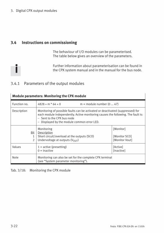
3. Digital CPX output modules
3-22 Festo P.BE-CPX-EA-EN en 1105h
3.4 Instructions on commissioning
The behaviour of I/O modules can be parameterised.The table below gives an overview of the parameters.
Further information about parameterisation can be found inthe CPX system manual and in the manual for the bus node.
3.4.1 Parameters of the output modules
Module parameters: Monitoring the CPX module
Function no. 4828 + m * 64 + 0 m = module number (0 ... 47)
Description Monitoring of possible faults can be activated or deactivated (suppressed) foreach module independently. Active monitoring causes the following. The fault is:– Sent to the CPX bus node– Displayed by the module common error LED.
Bit12
MonitoringDescriptionShort circuit/overload at the outputs (SCO)Undervoltage at outputs (VOUT)
[Monitor]
[Monitor SCO][Monitor Vout]
Values 1 = active (presetting)0 = inactive
[Active][Inactive]
Note Monitoring can also be set for the complete CPX terminal(see “System parameter monitoring”).
Tab. 3/18: Monitoring the CPX module
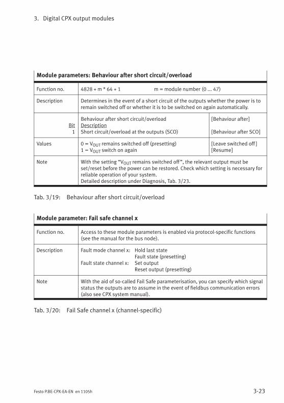
3. Digital CPX output modules
3-23Festo P.BE-CPX-EA-EN en 1105h
Module parameters: Behaviour after short circuit/overload
Function no. 4828 + m * 64 + 1 m = module number (0 ... 47)
Description Determines in the event of a short circuit of the outputs whether the power is toremain switched off or whether it is to be switched on again automatically.
Bit1
Behaviour after short circuit/overloadDescriptionShort circuit/overload at the outputs (SCO)
[Behaviour after]
[Behaviour after SCO]
Values 0 = VOUT remains switched off (presetting)1 = VOUT switch on again
[Leave switched off ][Resume]
Note With the setting “VOUT remains switched off”, the relevant output must beset/reset before the power can be restored. Check which setting is necessary forreliable operation of your system.Detailed description under Diagnosis, Tab. 3/23.
Tab. 3/19: Behaviour after short circuit/overload
Module parameter: Fail safe channel x
Function no. Access to these module parameters is enabled via protocol-specific functions(see the manual for the bus node).
Description Fault mode channel x: Hold last stateFault state (presetting)
Fault state channel x: Set outputReset output (presetting)
Note With the aid of so-called Fail Safe parameterisation, you can specify which signalstatus the outputs are to assume in the event of fieldbus communication errors(also see CPX system manual).
Tab. 3/20: Fail Safe channel x (channel-specific)
3. Digital CPX output modules
3-24 Festo P.BE-CPX-EA-EN en 1105h
Module parameters: Idle mode channel x
Function no. Access to these module parameters is enabled via protocol-specific functions(see the manual for the bus node).
Description Only relevant for certain fieldbus protocols.Idle mode channel x: Hold last state
Idle state (presetting)Idle state channel x: Set output
Reset output (presetting)
Note With the aid of so-called Idle Mode parameterisation, you can specify whichsignal status the outputs are to assume when switching is made to the Idle state(also see CPX system manual).This parameter is not available with all fieldbus protocols.
Tab. 3/21: Idle mode channel x (channel-specific)
Module parameters: Force channel x
Function no. Access to these module parameters is enabled via protocol-specific functions(see the manual for the bus node).
Description Force mode of outputs channel x: Blocked (presetting)Force state
Force state of outputs channel x: Set signalReset signal (presetting)
Note The Force function enables the manipulation of signal states detached fromactual operating states (also refer to the CPX system manual).
Tab. 3/22: Force channel x (channel-specific)

3. Digital CPX output modules
3-25Festo P.BE-CPX-EA-EN en 1105h
3.5 Diagnosis
Specific faults of the output modules are registered orsuppressed depending on module parameterisation.
The faults are indicated locally via the Error LED and, ifnecessary, they can be evaluated with the handheld (MMI).
The faults are sent to the bus node (depending on moduleparameterisation), where they can be evaluated according tothe fieldbus protocol used.

3. Digital CPX output modules
3-26 Festo P.BE-CPX-EA-EN en 1105h
3.5.1 Error messages of the output modules
An output module can register the following standard faults:
Error number Description Error handling
2 Fault short circuit/overloadShort circuit/overload at output.
The reaction depends on theparameterisation “Behaviourafter short circuit/overload atoutputs (SCO)”:– Setting “VOUT remains
switched off” (default):The output is switched off
1. Check actuators, eliminate short circuit/overload (number of faulty channel: see LEDdisplay or module diagnostic data).
2. Depending on the parameterisation“Behaviour after short circuit/overload atoutputs (SCO)”:
• Set output to 0, then set to 1 again ormodify parameter “Behaviour after shortcircuit/overload at outputs (SCO)” to“VOUT switch on again”.
only CPX-8DA:– Setting “VOUT switch on
again”:The output current is limitedto approx. 250 mA.
• If the output current is lower than 400 mA:The voltage will be switched on againautomatically when the short circuit iseliminated.
• If the output current is greater than400 mA:Set output to 0, then set to 1 again.
only CPX-8DA-H:– Setting “VOUT switch on
again”• If the output current is lower than 2.1 mA:
The voltage will be switched on againautomatically when the short circuit iseliminated.
• If the output current is greater than 2.5 A,the output begins to pulse. The fre-quency and duration of the pulse dependon temperature and overloading/currentvalue (see “Technical specifications”,chapter A.4)
5 Fault in load voltage for outputsLoad voltage for outputs (VOUT)missing or too low. 1)
• Check the load voltage
1) Tolerance range of the load voltage supply VOUT see “Technical specifications” in the appendix.
Tab. 3/23: Error messages of the output modules
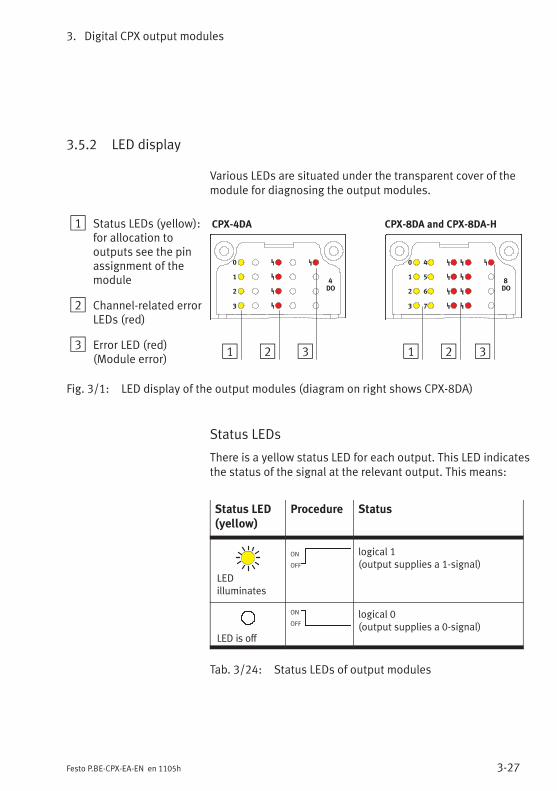
3. Digital CPX output modules
3-27Festo P.BE-CPX-EA-EN en 1105h
3.5.2 LED display
Various LEDs are situated under the transparent cover of themodule for diagnosing the output modules.
1 Status LEDs (yellow):for allocation tooutputs see the pinassignment of themodule
2 Channel-related errorLEDs (red)
3 Error LED (red)(Module error)
0
1
2
3
4
DO
1 2
CPX-4DA
3
0
1
2
3
8
DO
CPX-8DA and CPX-8DA-H
1
4
5
6
7
2 3
Fig. 3/1: LED display of the output modules (diagram on right shows CPX-8DA)
Status LEDs
There is a yellow status LED for each output. This LED indicatesthe status of the signal at the relevant output. This means:
Status LED(yellow)
Procedure Status
LEDilluminates
ON
OFF
logical 1(output supplies a 1-signal)
LED is off
ON
OFF
logical 0(output supplies a 0-signal)
Tab. 3/24: Status LEDs of output modules

3. Digital CPX output modules
3-28 Festo P.BE-CPX-EA-EN en 1105h
Channel-related error LEDs
There is a red error LED for each output. This indicates a faultat the output due to short circuit or overload irrespective ofthe parameterisation.
Channel-related errorLED (red)
Procedure Status Errornumber
Error handling
LED is off
ON
OFF
Output without short circuit/overload, trouble-free operation.
0 None
LEDilluminates
ON
OFF
Fault short circuit/overloadShort circuit/overload at output.
2 See section3.5.1, Tab. 3/23.
Tab. 3/25: Channel-related error LEDs of output modules
Error LED
The red error LED indicates the following faults depending onparameterisation:
Error LED(red)
Procedure Status Errornumber
Error handling
LED is off
ON
OFF
No module error has occurred. 0 None
LEDilluminates
ON
OFF
Fault short circuit/overloadShort circuit/overload at output.
2 See section3.5.1, Tab. 3/23.
Fault in load voltage for outputsLoad voltage for outputs (VOUT)missing or too low.
5
Tab. 3/26: Error LED of output modules

3. Digital CPX output modules
3-29Festo P.BE-CPX-EA-EN en 1105h
3.5.3 Error handling and parameterisation
The following diagram shows the error handling procedure inthe output modules. Further registering and display of thefaults can be suppressed as desired with the appropriatemodule parameters (represented in the diagram as switches).The parameters are described in section 3.4.
2
Error message tobus node
...
Fault no. 5
Fault in loadvoltage foroutputs
Fault no. 2
Short circuit/overload atoutput 0
Fault no. 2
Short circuit/overload atoutput 3
Monitoring
VOUT
Monitoring
SCO
ModuleError LED
3
1
Channel-related errorLED channel 3
Channel-related errorLED channel 0
...
0 1 0 1
1 Module parameters (switch position represented = default setting)
2 Module-specific faults
3 Channel-specific faults
Fig. 3/2: Principle of error handling and parameterisation in the output modules

3. Digital CPX output modules
3-30 Festo P.BE-CPX-EA-EN en 1105h
Digital CPX multi I/O modules
4-1Festo P.BE-CPX-EA-EN en 1105h
Chapter 4
Type CPX-8DE-8DA
CPX-L-8DE-8DA-16-KL-3POL
Digital CPX multi I/O modules
4. Digital CPX multi I/O modules
4-2 Festo P.BE-CPX-EA-EN en 1105h
Contents
4. Digital CPX multi I/O modules 4-1. . . . . . . . . . . . . . . . . . . . . . . . . . . . . . . . . . . .
4.1 Function of multi I/O modules 4-3. . . . . . . . . . . . . . . . . . . . . . . . . . . . . . . . . . . . .
4.2 Assembly 4-3. . . . . . . . . . . . . . . . . . . . . . . . . . . . . . . . . . . . . . . . . . . . . . . . . . . . .
4.3 Installation 4-4. . . . . . . . . . . . . . . . . . . . . . . . . . . . . . . . . . . . . . . . . . . . . . . . . . . .
4.3.1 Multi I/O module CPX-8DE-8DA 4-5. . . . . . . . . . . . . . . . . . . . . . . . . . . .
4.3.2 Multi I/O module CPX-L-8DE-8DA-… 4-9. . . . . . . . . . . . . . . . . . . . . . . . .
4.4 Instructions on commissioning 4-10. . . . . . . . . . . . . . . . . . . . . . . . . . . . . . . . . . . .
4.4.1 Parameters of the multi I/O modules type CPX-8DE-8DA 4-10. . . . . . . .
4.5 Diagnosis 4-16. . . . . . . . . . . . . . . . . . . . . . . . . . . . . . . . . . . . . . . . . . . . . . . . . . . . .
4.5.1 Error messages of the multi I/O modules 4-16. . . . . . . . . . . . . . . . . . . .
4.5.2 LED display 4-18. . . . . . . . . . . . . . . . . . . . . . . . . . . . . . . . . . . . . . . . . . . .
4.5.3 Error handling and parameterisation 4-21. . . . . . . . . . . . . . . . . . . . . . . .

4. Digital CPX multi I/O modules
4-3Festo P.BE-CPX-EA-EN en 1105h
4.1 Function of multi I/O modules
Multi I/O modules provide digital inputs in the valve terminalfor connecting sensors as well as digital outputs for connect-ing electric actuators and other current-consuming devices(valves, contactors, displays). At present the following type isavailable:
Type Description
CPX-8DE-8DA Provides 8 digital inputs and8 digital outputs (each as perIEC 61131-2 type 2, 24 V,positive logic – PNP).
CPX-L-8DE-8DA-16-KL-3POL
Provides 8 digital inputs(as per IEC 61131-2 type 1, 24 V,positive logic – PNP) as well as8 digital outputs (as perIEC 61131-2 , 24 V, positivelogic – PNP).CPX-L modules do not have anyexchangeable connectionblocks.
Tab. 4/1: Overview of multi I/O modules
4.2 Assembly
See section 1.3.
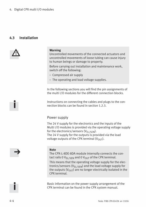
4. Digital CPX multi I/O modules
4-4 Festo P.BE-CPX-EA-EN en 1105h
4.3 Installation
WarningUncontrolled movements of the connected actuators anduncontrolled movements of loose tubing can cause injuryto human beings or damage to property.
Before carrying out installation and maintenance work,switch off the following:
– Compressed air supply
– The operating and load voltage supplies.
In the following sections you will find the pin assignments ofthe multi I/O modules for the different connection blocks.
Instructions on connecting the cables and plugs to the con-nection blocks can be found in section 1.2.3.
Power supply
The 24 V supply for the electronics and the inputs of theMulti I/O modules is provided via the operating voltage supplyfor the electronics/sensors (VEL/SEN).The 24 V supply for the outputs is provided via the loadvoltage outputs of the CPX terminal (VOUT).
NoteThe CPX-L-8DE-8DA module internally connects the con-tact rails 0 VEL/SEN and 0 VOUT of the CPX terminal.
This means that the operating voltage supply for the elec-tronics/sensors (VEL/SEN) and the load voltage supply forthe outputs (VOUT) are no longer electrically isolated in theCPX terminal.
Basic information on the power supply arrangement of theCPX terminal can be found in the CPX system manual.
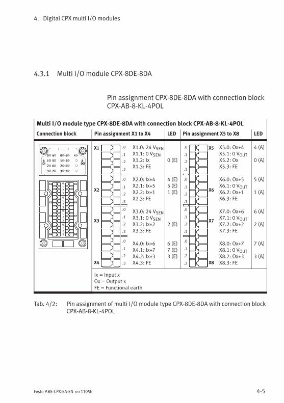
4. Digital CPX multi I/O modules
4-5Festo P.BE-CPX-EA-EN en 1105h
4.3.1 Multi I/O module CPX-8DE-8DA
Pin assignment CPX-8DE-8DA with connection blockCPX-AB-8-KL-4POL
Multi I/O module type CPX-8DE-8DA with connection block CPX-AB-8-KL-4POL
Connection block Pin assignment X1 to X4 LED Pin assignment X5 to X8 LED
0
1
2
3
8DI
4
5
6
7
X1
X2
X3
X4
X5
X6
X7
X8
.0
.1
.2
.3
.0
.1
.2
.3
.0
.1
.2
.3
.0
.1
.2
.3
0
1
2
3
4
5
6
7
8DO
X1
X2
X3
X4
.0
.1
.2
.3
.0
.1
.2
.3
.0
.1
.2
.3
.0
.1
.2
.3
X1.0: 24 VSENX1.1: 0 VSENX1.2: IxX1.3: FE
X2.0: Ix+4X2.1: Ix+5X2.2: Ix+1X2.3: FE
X3.0: 24 VSENX3.1: 0 VSENX3.2: Ix+2X3.3: FE
X4.0: Ix+6X4.1: Ix+7X4.2: Ix+3X4.3: FE
0 (E)
4 (E)5 (E)1 (E)
2 (E)
6 (E)7 (E)3 (E)
X5
X6
X7
X8
.0
.1
.2
.3
.0
.1
.2
.3
.0
.1
.2
.3
.0
.1
.2
.3
X5.0: Ox+4X5.1: 0 VOUTX5.2: OxX5.3: FE
X6.0: Ox+5X6.1: 0 VOUTX6.2: Ox+1X6.3: FE
X7.0: Ox+6X7.1: 0 VOUTX7.2: Ox+2X7.3: FE
X8.0: Ox+7X8.1: 0 VOUTX8.2: Ox+3X8.3: FE
4 (A)
0 (A)
5 (A)
1 (A)
6 (A)
2 (A)
7 (A)
3 (A)
Ix = Input xOx = Output xFE = Functional earth
Tab. 4/2: Pin assignment of multi I/O module type CPX-8DE-8DA with connection blockCPX-AB-8-KL-4POL
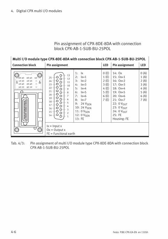
4. Digital CPX multi I/O modules
4-6 Festo P.BE-CPX-EA-EN en 1105h
Pin assignment of CPX-8DE-8DA with connectionblock CPX-AB-1-SUB-BU-25POL
Multi I/O module type CPX-8DE-8DA with connection block CPX-AB-1-SUB-BU-25POL
Connection block Pin assignment LED Pin assignment LED
0
1
2
3
8
DI
4
5
6
7
0
1
2
3
4
5
6
7
8
DO
1
2
3
4
5
6
7
8
9
10
11
12
13
14
15
16
17
18
19
20
21
22
23
24
25
1: Ix2: Ix+13: Ix+24: Ix+35: Ix+46: Ix+57: Ix+68: Ix+79: 24 VSEN10: 24 VSEN11: 0 VSEN12: 0 VSEN13: FE
0 (E)1 (E)2 (E)3 (E)4 (E)5 (E)6 (E)7 (E)
14: Ox15: Ox+116: Ox+217: Ox+318: Ox+419: Ox+520: Ox+621: Ox+722: 0 VOUT23: 0 VOUT24: 0 VOUT25: FEHousing: FE
0 (A)1 (A)2 (A)3 (A)4 (A)5 (A)6 (A)7 (A)
Ix = Input xOx = Output xFE = Functional earth
Tab. 4/3: Pin assignment of multi I/O module type CPX-8DE-8DA with connection blockCPX-AB-1-SUB-BU-25POL

4. Digital CPX multi I/O modules
4-7Festo P.BE-CPX-EA-EN en 1105h
Pin assignment CPX-8DE-8DA with connection blockCPX-AB-4-M12-8POL
NoteIn the multi I/O module CPX-8DE-8DA with connectionblock CPX-AB-4-M12-8POL the inputs Ix+4 and Ix+6 areavailable on sockets X1 and X3 resp. X2 and X4(connected internally).
Multi I/O module type CPX-8DE-8DA with connection block CPX-AB-4-M12-8POL
Connection block Pin assignment X1, X2 LED Pin assignment X3, X4 LED
0
1
2
3
8DI
4
5
6
7
0
1
2
3
4
5
6
7
8DO
2
3
1
5
4
X2
8
6
7
2
3
1
5
4
X1
8
6
7
Socket X1:1: 24 VSEN2: Ix3: Ix+14: 0 VSEN5: Ox6: Ox+17: Ix+48: 0 VOUT
Socket X2:1: 24 VSEN2: Ix+23: Ix+34: 0 VSEN5: Ox+26: Ox+37: Ix+68: 0 VOUT
0 (E)1 (E)
0 (A)1 (A)4 (E)
2 (E)3 (E)
2 (A)3 (A)6 (E)
2
3
1
5
4
X4
8
6
7
2
3
1
5
4
X3
8
6
7
Socket X3:1: 24 VSEN2: Ix+43: Ix+54: 0 VSEN5: Ox+46: Ox+57: n.c.8: 0 VOUT
Socket X4:1: 24 VSEN2: Ix+63: Ix+74: 0 VSEN5: Ox+66: Ox+77: n.c.8: 0 VOUT
4 (E)5 (E)
4 (A)5 (A)
6 (E)7 (E)
6 (A)7 (A)
Ix = Input xOx = Output xn.c. = Not connected
Tab. 4/4: Pin assignment of multi I/O module type CPX-8DE-8DA with connection blockCPX-AB-4-M12x2-5POL
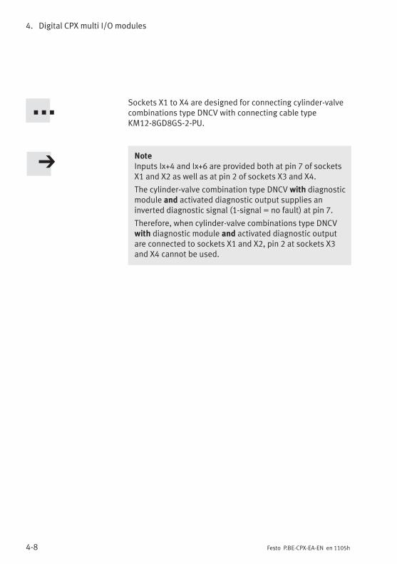
4. Digital CPX multi I/O modules
4-8 Festo P.BE-CPX-EA-EN en 1105h
Sockets X1 to X4 are designed for connecting cylinder-valvecombinations type DNCV with connecting cable typeKM12-8GD8GS-2-PU.
NoteInputs Ix+4 and Ix+6 are provided both at pin 7 of socketsX1 and X2 as well as at pin 2 of sockets X3 and X4.
The cylinder-valve combination type DNCV with diagnosticmodule and activated diagnostic output supplies aninverted diagnostic signal (1-signal = no fault) at pin 7.
Therefore, when cylinder-valve combinations type DNCVwith diagnostic module and activated diagnostic outputare connected to sockets X1 and X2, pin 2 at sockets X3and X4 cannot be used.

4. Digital CPX multi I/O modules
4-9Festo P.BE-CPX-EA-EN en 1105h
4.3.2 Multi I/O module CPX-L-8DE-8DA-…
CPX-L modules do not have any exchangeable connectionblocks.
NoteWhen using 2-wire sensors the residual current at “log. 0”must be smaller than the standard value as per IEC61131-2type 1. VIx, Ix+1,… < 5 V: Iresidual < 500 µA.
• Observe the instructions for power supply in section 4.3.
Pin assignment CPX-L-8DE-8DA-…
I-module type CPX-L-8DE-8DA-16-KL-3POL
Connection block Pin assignment X1 to X8 Pin assignment X9 to X16
X1.0: 24 VSENX1.1: IxX1.2: 0 VSENX2.0: 24 VSENX2.1: Ix+1X2.2: 0 VSENX3.0: 24 VSENX3.1: Ix+2X3.2: 0 VSENX4.0: 24 VSENX4.1: Ix+3X4.2: 0 VSENX5.0: 24 VSENX5.1: Ix+4X5.2: 0 VSENX6.0: 24 VSENX6.1: Ix+5X6.2: 0 VSENX7.0: 24 VSENX7.1: Ix+6X7.2: 0 VSENX8.0: 24 VSENX8.1: Ix+7X8.2: 0 VSEN
X9.0: 24 VSENX9.1: OxX9.2: 0 VOUTX10.0: 24 VSENX10.1: Ox+1X10.2: 0 VOUTX11.0: 24 VSENX11.1: Ox+2X11.2: 0 VOUTX12.0: 24 VSENX12.1: Ox+3X12.2: 0 VOUTX13.0: 24 VSENX13.1: Ox+4X13.2: 0 VOUTX14.0: 24 VSENX14.1: Ox+5X14.2: 0 VOUTX15.0: 24 VSENX15.1: Ox+6X15.2: 0 VOUTX16.0: 24 VSENX16.1: Ox+7X16.2: 0 VOUT
Ix = Input x Ox = Output x, 24 VSENis not required for the outputs
Tab. 4/5: Pin assignment of I-module type CPX-L-8DE-8DA-…

4. Digital CPX multi I/O modules
4-10 Festo P.BE-CPX-EA-EN en 1105h
4.4 Instructions on commissioning
The behaviour of I/O modules can be parameterised. Thetable below gives an overview of the parameters.
Further information about parameterisation can be found inthe CPX system manual or in the manual for the bus node.
4.4.1 Parameters of the multi I/O modules type CPX-8DE-8DA
Module parameters: Monitoring the CPX module
Function no. 4828 + m * 64 + 0 m = module number (0 ... 47)
Description Monitoring of possible faults can be activated or deactivated (suppressed) foreach module independently. Active monitoring causes the following. The fault is:– Sent to the CPX bus node– Displayed by the module common error LED.
Bit012
MonitoringDescriptionShort circuit/overload in sensor supply (SCS)Short circuit/overload at the outputs (SCO)Undervoltage at outputs (VOUT)
[Monitor]
[Monitor SCS][Monitor SCO][Monitor Vout]
Values 1 = active (presetting)0 = inactive
[Active][Inactive]
Note Monitoring can also be set for the complete CPX terminal(see “System parameter monitoring”).
Tab. 4/6: Monitoring the CPX module

4. Digital CPX multi I/O modules
4-11Festo P.BE-CPX-EA-EN en 1105h
Module parameters: Behaviour after short circuit/overload
Function no. 4828 + m * 64 + 1 m = module number (0 ... 47)
Description Determines after a short circuit in the sensor supply or the outputs whether thepower is to remain switched off or whether it is to be switched on again auto-matically.
Bit01
Behaviour after short circuit/overloadDescriptionShort circuit/overload in sensor supply (SCS)Short circuit/overload at the outputs (SCO)
[Behaviour after]
[Behaviour after SCS][Behaviour after SCO]
Values 0 = VSEN/VOUT remains switched off1 = VSEN/VOUT switch on againPresetting: Bit 0: VSEN/VOUT switch on again;
Bit 1: VSEN/VOUT remains switched off
[Leave switched off ][Resume]
Note With the setting “VSEN/OUT remains switched off”, Power On/Off or Set/Reset isrequired to restore power. Check which setting is necessary for reliableoperation of your system.Detailed description under Diagnosis, Tab. 4/15.
Tab. 4/7: Behaviour after short circuit/overload
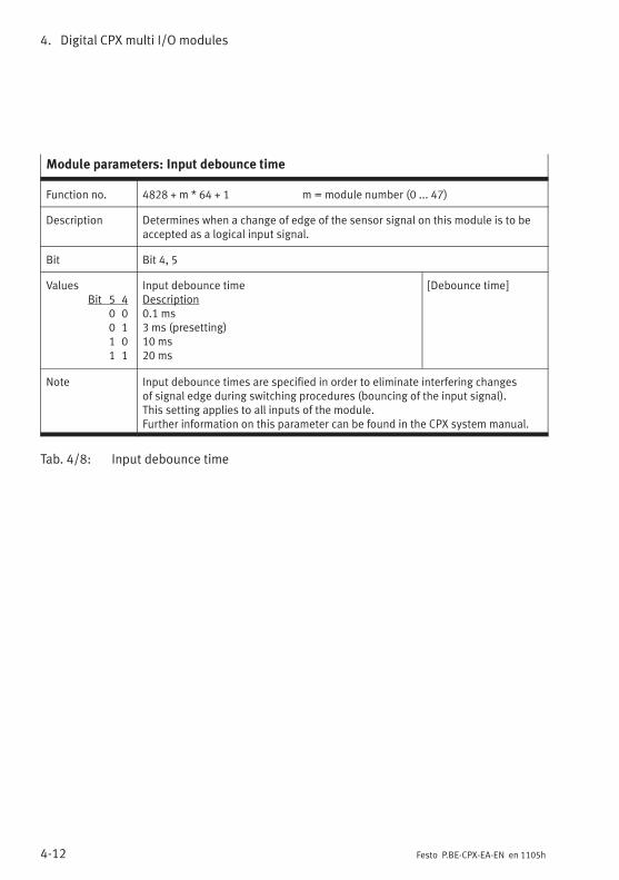
4. Digital CPX multi I/O modules
4-12 Festo P.BE-CPX-EA-EN en 1105h
Module parameters: Input debounce time
Function no. 4828 + m * 64 + 1 m = module number (0 ... 47)
Description Determines when a change of edge of the sensor signal on this module is to beaccepted as a logical input signal.
Bit Bit 4, 5
ValuesBit 5 4
0 00 11 01 1
Input debounce timeDescription0.1 ms3 ms (presetting)10 ms20 ms
[Debounce time]
Note Input debounce times are specified in order to eliminate interfering changesof signal edge during switching procedures (bouncing of the input signal).This setting applies to all inputs of the module.Further information on this parameter can be found in the CPX system manual.
Tab. 4/8: Input debounce time
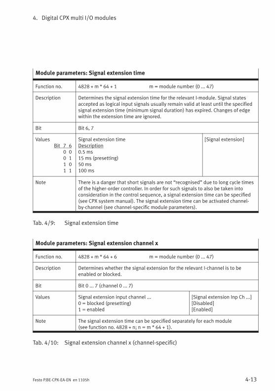
4. Digital CPX multi I/O modules
4-13Festo P.BE-CPX-EA-EN en 1105h
Module parameters: Signal extension time
Function no. 4828 + m * 64 + 1 m = module number (0 ... 47)
Description Determines the signal extension time for the relevant I-module. Signal statesaccepted as logical input signals usually remain valid at least until the specifiedsignal extension time (minimum signal duration) has expired. Changes of edgewithin the extension time are ignored.
Bit Bit 6, 7
ValuesBit 7 6
0 00 11 01 1
Signal extension timeDescription0.5 ms15 ms (presetting)50 ms100 ms
[Signal extension]
Note There is a danger that short signals are not “recognised” due to long cycle timesof the higher-order controller. In order for such signals to also be taken intoconsideration in the control sequence, a signal extension time can be specified(see CPX system manual). The signal extension time can be activated channel-by-channel (see channel-specific module parameters).
Tab. 4/9: Signal extension time
Module parameters: Signal extension channel x
Function no. 4828 + m * 64 + 6 m = module number (0 ... 47)
Description Determines whether the signal extension for the relevant I-channel is to beenabled or blocked.
Bit Bit 0 ... 7 (channel 0 ... 7)
Values Signal extension input channel ...0 = blocked (presetting)1 = enabled
[Signal extension Inp Ch ...][Disabled][Enabled]
Note The signal extension time can be specified separately for each module(see function no. 4828 + n; n = m * 64 + 1).
Tab. 4/10: Signal extension channel x (channel-specific)

4. Digital CPX multi I/O modules
4-14 Festo P.BE-CPX-EA-EN en 1105h
Module parameter: Fail safe channel x
Function no. Access to these module parameters is enabled via protocol-specific functions(see the manual for the bus node).
Description Fault mode channel x: Hold last stateFault state (presetting)
Fault state channel x: Set outputReset output (presetting)
Note With the aid of so-called Fail Safe parameterisation, you can specify which signalstatus the outputs are to assume in the event of fieldbus communication errors(also see CPX system manual).
Tab. 4/11: Fail Safe channel x (channel-specific)
Module parameters: Idle mode channel x
Function no. Access to these module parameters is enabled via protocol-specific functions(see the manual for the bus node).
Description Only relevant for certain fieldbus protocols.Idle mode channel x: Hold last state
Idle state (presetting)Idle state channel x: Set output
Reset output (presetting)
Note With the aid of so-called Idle Mode parameterisation, you can specify whichsignal status the outputs are to assume when switching is made to the Idle state(also see CPX system manual).This parameter is not available with all fieldbus protocols.
Tab. 4/12: Idle mode channel x (channel-specific)

4. Digital CPX multi I/O modules
4-15Festo P.BE-CPX-EA-EN en 1105h
Module parameters: Force channel x
Function no. Access to these module parameters is enabled via protocol-specific functions(see the manual for the bus node).
Description Force mode of inputs channel x: Blocked (presetting)Force state
Force state of inputs channel x: Set signalReset signal (presetting)
Force mode of outputs channel x: Blocked (presetting)Force state
Force state of outputs channel x: Set signalReset signal (presetting)
Note The Force function enables the manipulation of signal states detached fromactual operating states (also refer to the CPX system manual).
Tab. 4/13: Force channel x (channel-specific)

4. Digital CPX multi I/O modules
4-16 Festo P.BE-CPX-EA-EN en 1105h
4.5 Diagnosis
Specific faults of the multi I/O modules are registered orsuppressed depending on module parameterisation.
The faults are indicated locally via the Error LED and, ifnecessary, they can be evaluated with the handheld (MMI).
The faults are sent to the bus node (depending on moduleparameterisation), where they can be evaluated according tothe fieldbus protocol used.
4.5.1 Error messages of the multi I/O modules
A multi I/O module can register the following standard faults:
Error number Description Error handling
2 Fault short circuit/overload– Short circuit/overload in sensor
supply (VEL/SEN).
or (see continuation)
1. Eliminate short circuit/overload or checkconnected sensors
2. Depending on the parameterisation“Behaviour after short circuit/overload insensor supply (SCS)”:• Setting “VSEN switch on again”:
Power supply for sensors will beswitched on again automatically whenthe short circuit is eliminated.
• Setting “VSEN remains switched off”:– Power Off/On necessaryor– modify parameter “Behaviour aftershort circuit/overload at sensor supply(SCS)” to “VSEN switch on again”.
Tab. 4/14: Error messages of the multi I/O modules – part 1
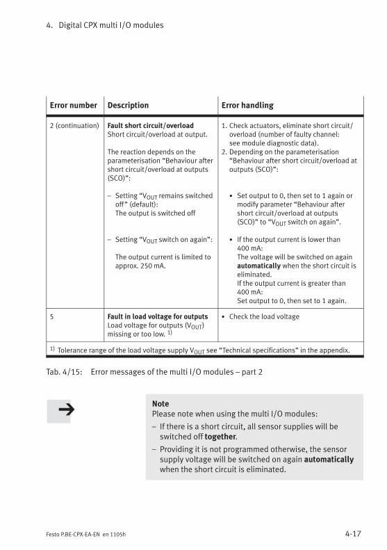
4. Digital CPX multi I/O modules
4-17Festo P.BE-CPX-EA-EN en 1105h
Error number Description Error handling
2 (continuation) Fault short circuit/overloadShort circuit/overload at output.
The reaction depends on theparameterisation “Behaviour aftershort circuit/overload at outputs(SCO)”:
– Setting “VOUT remains switchedoff” (default):The output is switched off
– Setting “VOUT switch on again”:
The output current is limited toapprox. 250 mA.
1. Check actuators, eliminate short circuit/overload (number of faulty channel:see module diagnostic data).
2. Depending on the parameterisation“Behaviour after short circuit/overload atoutputs (SCO)”:
• Set output to 0, then set to 1 again ormodify parameter “Behaviour aftershort circuit/overload at outputs(SCO)” to “VOUT switch on again”.
• If the output current is lower than400 mA:The voltage will be switched on againautomatically when the short circuit iseliminated.If the output current is greater than400 mA:Set output to 0, then set to 1 again.
5 Fault in load voltage for outputsLoad voltage for outputs (VOUT)missing or too low. 1)
• Check the load voltage
1) Tolerance range of the load voltage supply VOUT see “Technical specifications” in the appendix.
Tab. 4/15: Error messages of the multi I/O modules – part 2
NotePlease note when using the multi I/O modules:
– If there is a short circuit, all sensor supplies will beswitched off together.
– Providing it is not programmed otherwise, the sensorsupply voltage will be switched on again automaticallywhen the short circuit is eliminated.

4. Digital CPX multi I/O modules
4-18 Festo P.BE-CPX-EA-EN en 1105h
4.5.2 LED display
Various LEDs for diagnosing the multi I/O modules aresituated under the transparent cover of the module. The LEDsare located directly next to the ports for channel-orienteddiagnostics of the CPX-L multi I/O modules.
0
1
2
3
8
DI
4
5
6
7
1 2
CPX-8DE-8DA
0
1
2
3
4
5
6
7
8
DO
3
CPX-L-8DE-8DA-16-KL-…
34 5
1 Status LEDs (green): for assignment tothe inputs see the pin assignment ofthe module
2 Status LEDs (yellow): for allocation tooutputs see the pin assignment of themodule
3 Error LED (red): Module fault
4 Status LEDs (green) for the inputs
5 Status LEDs (yellow) for the outputs
Fig. 4/1: LED display of the multi I/O modules
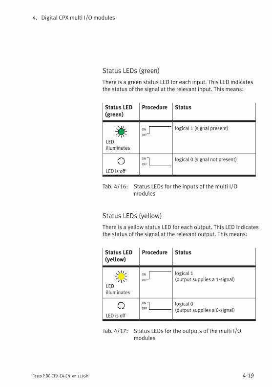
4. Digital CPX multi I/O modules
4-19Festo P.BE-CPX-EA-EN en 1105h
Status LEDs (green)
There is a green status LED for each input. This LED indicatesthe status of the signal at the relevant input. This means:
Status LED(green)
Procedure Status
LEDilluminates
ON
OFF
logical 1 (signal present)
LED is off
ON
OFF
logical 0 (signal not present)
Tab. 4/16: Status LEDs for the inputs of the multi I/Omodules
Status LEDs (yellow)
There is a yellow status LED for each output. This LED indicatesthe status of the signal at the relevant output. This means:
Status LED(yellow)
Procedure Status
LEDilluminates
ON
OFF
logical 1(output supplies a 1-signal)
LED is off
ON
OFF
logical 0(output supplies a 0-signal)
Tab. 4/17: Status LEDs for the outputs of the multi I/Omodules
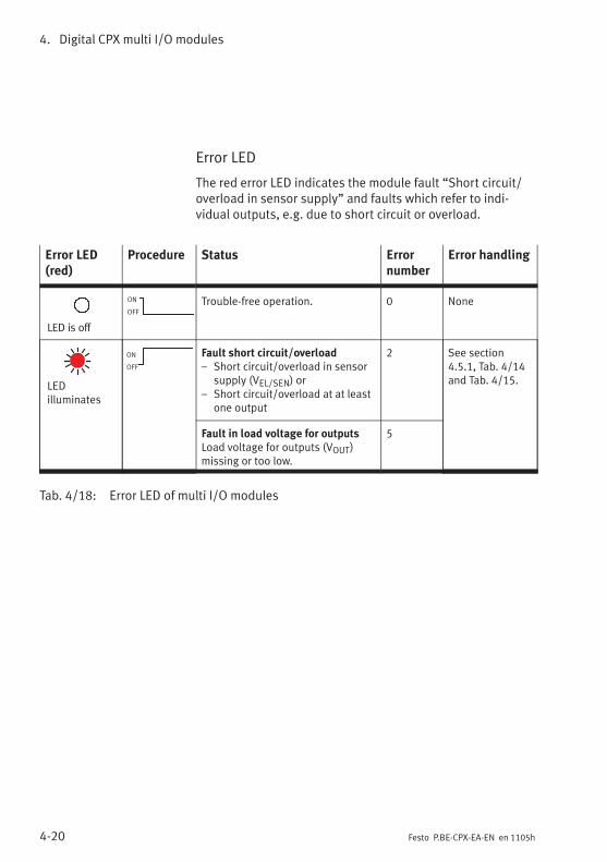
4. Digital CPX multi I/O modules
4-20 Festo P.BE-CPX-EA-EN en 1105h
Error LED
The red error LED indicates the module fault “Short circuit/overload in sensor supply” and faults which refer to indi-vidual outputs, e.g. due to short circuit or overload.
Error LED(red)
Procedure Status Errornumber
Error handling
LED is off
ON
OFF
Trouble-free operation. 0 None
LEDilluminates
ON
OFF
Fault short circuit/overload– Short circuit/overload in sensor
supply (VEL/SEN) or– Short circuit/overload at at least
one output
2 See section4.5.1, Tab. 4/14and Tab. 4/15.
Fault in load voltage for outputsLoad voltage for outputs (VOUT)missing or too low.
5
Tab. 4/18: Error LED of multi I/O modules
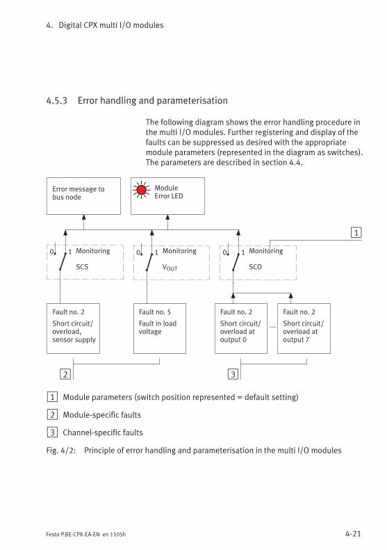
4. Digital CPX multi I/O modules
4-21Festo P.BE-CPX-EA-EN en 1105h
4.5.3 Error handling and parameterisation
The following diagram shows the error handling procedure inthe multi I/O modules. Further registering and display of thefaults can be suppressed as desired with the appropriatemodule parameters (represented in the diagram as switches).The parameters are described in section 4.4.
2
Fault no. 2
Short circuit/overload,sensor supply
Error message tobus node
...
Fault no. 5
Fault in loadvoltage
Fault no. 2
Short circuit/overload atoutput 0
Fault no. 2
Short circuit/overload atoutput 7
Monitoring
SCS
Monitoring
VOUT
Monitoring
SCO
ModuleError LED
3
1
0 1 0 1 0 1
1 Module parameters (switch position represented = default setting)
2 Module-specific faults
3 Channel-specific faults
Fig. 4/2: Principle of error handling and parameterisation in the multi I/O modules

4. Digital CPX multi I/O modules
4-22 Festo P.BE-CPX-EA-EN en 1105h

CPX pneumatic interfaces
5-1Festo P.BE-CPX-EA-EN en 1105h
Chapter 5
Type VMPA-FB-EPL-...
VMPAF-FB-EPL-PSVMPAL-EPL-CPX
VABA-S6-1-X1VABA-S6-1-X2
CPX-GP-03-4.0
CPX-GP-CPA-10CPX-GP-CPA-14
CPX pneumatic interfaces
5. CPX pneumatic interfaces
5-2 Festo P.BE-CPX-EA-EN en 1105h
Contents
5. CPX pneumatic interfaces 5-1. . . . . . . . . . . . . . . . . . . . . . . . . . . . . . . . . . . . . . . .
5.1 Function of the CPX pneumatic interfaces 5-3. . . . . . . . . . . . . . . . . . . . . . . . . . .
5.1.1 Display and connecting elements 5-5. . . . . . . . . . . . . . . . . . . . . . . . . . .
5.2 Assembly 5-9. . . . . . . . . . . . . . . . . . . . . . . . . . . . . . . . . . . . . . . . . . . . . . . . . . . . .
5.3 Settings for configuring the pneumatics 5-10. . . . . . . . . . . . . . . . . . . . . . . . . . . . .
5.4 Installation 5-15. . . . . . . . . . . . . . . . . . . . . . . . . . . . . . . . . . . . . . . . . . . . . . . . . . . .
5.5 Instructions on commissioning, parameterisation 5-16. . . . . . . . . . . . . . . . . . . . .
5.6 Diagnosis 5-20. . . . . . . . . . . . . . . . . . . . . . . . . . . . . . . . . . . . . . . . . . . . . . . . . . . . .
5.6.1 Fault messages of the pneumatic interfaces 5-21. . . . . . . . . . . . . . . . . .
5.6.2 LED display 5-22. . . . . . . . . . . . . . . . . . . . . . . . . . . . . . . . . . . . . . . . . . . .
5.6.3 Error handling and parameterisation 5-24. . . . . . . . . . . . . . . . . . . . . . . .

5. CPX pneumatic interfaces
5-3Festo P.BE-CPX-EA-EN en 1105h
5.1 Function of the CPX pneumatic interfaces
The CPX pneumatic interfaces in a CPX valve terminal providethe connection to the pneumatic modules.The pneumatic modules enable pneumatic actuators to becontrolled by means of the valves fitted.
Pneumaticinterfaces
Type designation Description Connection toPneumatics
– VMPA-FB-EPL-…
– VMPA-FB-EPLM-…
CPX pneumatic interfaceto MPA
CPX pneumatic interfaceto MPA (CPX metal)
Pneumatic interface forconnecting the modularelectrical peripherals oftype 50 (CPX) to valveterminals type 32/33(MPA-S, MPA-F)
– VMPAF-FB-EPL-PS CPX pneumatic interfaceto MPA with integratedpressure sensor
Pneumatic interface withintegrated pressuresensor for connecting themodular electricalperipherals (type 50) CPXto valve terminals type 33(MPA-F)
– VMPAL-EPL-CPX CPX pneumatic interfaceto MPA-L
Pneumatic interface forconnecting the modularelectrical peripherals oftype 50 (CPX) to valveterminals type MPA-L
– VABA-S6-1-X1– VABA-S6-1-X2
CPX pneumatic interfacefor VTSA pneumatics(ISO, type 44)…-X2: Metal design
Pneumatic interface forconnecting the modularelectrical peripherals oftype 50 (CPX) toVTSA/ISO valves(type 44)

5. CPX pneumatic interfaces
5-4 Festo P.BE-CPX-EA-EN en 1105h
Pneumaticinterfaces
Connection toPneumatics
DescriptionType designation
– CPX-GP-03-4.0 CPX pneumatic interfaceto Midi/Maxi
Pneumatic interface forconnecting the modularelectrical periphery type50 (CPX) to valveterminals type 03(Midi/Maxi).
– CPX-GP-CPA-10
– CPX-GP-CPA-14
CPX pneumatic interfaceto CPA10
CPX pneumatic interfaceto CPA14
Pneumatic interface forconnecting the modularelectrical periphery type50 (CPX) to valveterminals type 12 (CPA).
Tab. 5/1: Overview of pneumatic interfaces
MPA-S, MPA-F pneumatics From a technical point of view, the individual MPA-S andMPA-F pneumatic modules each represent an electricmodule with e.g. 8 digital outputs for controlling the valvesfitted (see manual P.BE-MPA-ELEKTRONIK-...).
NoteThe pneumatic interface VMPA…-FB-EPL-… for MPA pneu-matics provides the mechanical and electrical connectionto the MPA pneumatic modules.With regards to the CPX terminal it does not count as anelectric module.
MPA-L, VTSA, Midi/Maxior CPA pneumatics
With regards to the CPX terminal the pneumatic interfacesfor MPA-L, VTSA, Midi/Maxi or CPA pneumatics represent anelectrical module with a variable number of digital outputsfor triggering the built-in valves.
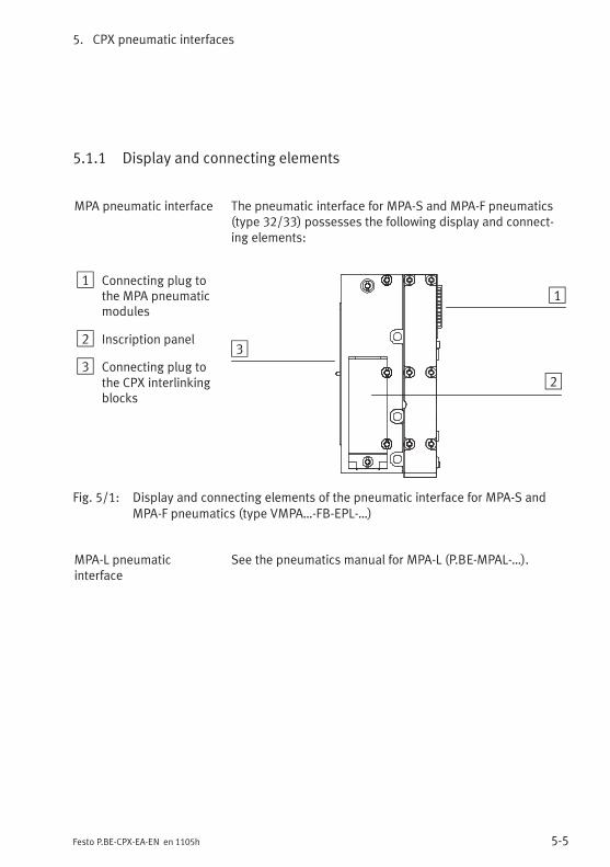
5. CPX pneumatic interfaces
5-5Festo P.BE-CPX-EA-EN en 1105h
5.1.1 Display and connecting elements
MPA pneumatic interface The pneumatic interface for MPA-S and MPA-F pneumatics(type 32/33) possesses the following display and connect-ing elements:
1 Connecting plug tothe MPA pneumaticmodules
2 Inscription panel
3 Connecting plug tothe CPX interlinkingblocks
1
2
3
Fig. 5/1: Display and connecting elements of the pneumatic interface for MPA-S andMPA-F pneumatics (type VMPA…-FB-EPL-…)
MPA-L pneumaticinterface
See the pneumatics manual for MPA-L (P.BE-MPAL-…).

5. CPX pneumatic interfaces
5-6 Festo P.BE-CPX-EA-EN en 1105h
MPA pneumatic interfacewith pressure sensor
The pneumatic interface for MPA-F pneumatics (type 33)with integrated pressure sensor possesses the followingdisplay and connecting elements:
1 Pneumaticinterface
2 Red LED:Pressure fallenbelow
3 Display
4 Green LED:Pressureconformed to
5 Red LED:Pressureexceeded
6 Red LED:Common errordisplay
7 Yellow LED “bar”:Value in displayshown in bar
8 Yellow LED “psi”:Value in displayshown in psi
1
2
3
4
5 6
7
8
Fig. 5/2: Display and connecting elements of the MPA-F pneumatic interface with pressuresensor (type VMPAF-FB-EPL…-PS)
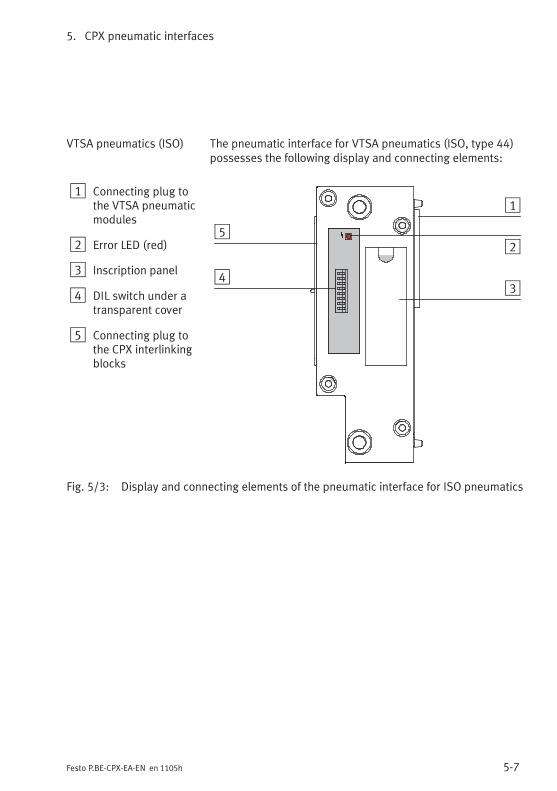
5. CPX pneumatic interfaces
5-7Festo P.BE-CPX-EA-EN en 1105h
VTSA pneumatics (ISO) The pneumatic interface for VTSA pneumatics (ISO, type 44)possesses the following display and connecting elements:
1 Connecting plug tothe VTSA pneumaticmodules
2 Error LED (red)
3 Inscription panel
4 DIL switch under atransparent cover
5 Connecting plug tothe CPX interlinkingblocks
1
2
34
5
Fig. 5/3: Display and connecting elements of the pneumatic interface for ISO pneumatics

5. CPX pneumatic interfaces
5-8 Festo P.BE-CPX-EA-EN en 1105h
Midi/Maxi orCPA pneumatics
The pneumatic interfaces for Midi/Maxi or CPA pneumaticspossess the following display and connecting elements:
1 Pneumatic interfacefor Midi/Maxipneumatics (type 03)
2 Pneumatic interfacefor CPA pneumatics(type 12 – heresize 10)
3 Connecting plug forthe valves
4 Fault LED (red)
5 DIL switch under atransparent cover
6 Inscription fields
7 Connecting plug tothe CPX interlinkingblocks
1 2
3
4
5
6
3
4
5
7 7
Fig. 5/4: Display and connecting elements of the pneumatic interface for Midi/Maxi orCPA pneumatics
Use identification labels type IBS 6x10 for marking thepneumatic interface for CPA pneumatics.
5. CPX pneumatic interfaces
5-9Festo P.BE-CPX-EA-EN en 1105h
5.2 Assembly
WarningUncontrolled movements of the connected actuators anduncontrolled movements of loose tubing can cause injuryto human beings or damage to property.
Before carrying out installation and maintenance work,switch off the following:
– Compressed air supply
– The operating and load voltage supplies.
Expanding or converting the CPX terminal:Depending on the version of the CPX terminal, pneumaticinterfaces are either screwed in place or secured with tierods. Further information can be found under the “Assembly”chapter in the CPX system manual.For information regarding assembly of the pneumaticmodules please refer to the appropriate pneumatics manual.
For Midi/Maxi, CPA or ISO pneumatic interfaces:The setting of the DIL switches for configuring the pneumatics(valves used) can be set on the CPX terminal without the needto dismantle the terminal.

5. CPX pneumatic interfaces
5-10 Festo P.BE-CPX-EA-EN en 1105h
5.3 Settings for configuring the pneumatics
Midi/Maxi, CPA orVTSA pneumatics
Settings for configuring the pneumatics are only necessarywith the pneumatic interfaces for Midi/Maxi, CPA and VTSApneumatics (ISO).
No settings are required for MPA pneumatics.
CautionAfter conversion or extension of the Midi/Maxi, CPA orVTSA pneumatics, the number of output addressesoccupied by the pneumatics must be set on a DIL switchon the pneumatic interface.
CPX terminals can be fitted with various valves and electricmodules in accordance with the customer's wishes.
The size of the valve address range on Midi/Max, CPA orVTSA pneumatics is not modified when the valves are extendedor converted, providing sufficient address space has alreadybeen reserved for the extension. The valve address rangemust be set with a DIL switch. The DIL switch is situatedunder the transparent cover on the pneumatic interface.
WarningUncontrolled movements of the connected actuators anduncontrolled movements of loose tubing can cause injuryto human beings or damage to property.
Before carrying out installation and maintenance work,switch off the following:
– Compressed air supply
– The operating and load voltage supplies.

5. CPX pneumatic interfaces
5-11Festo P.BE-CPX-EA-EN en 1105h
CautionInappropriate handling can result in damage to themodules.
• Do not touch any components.
• Observe the handling specifications for electrostaticsensitive devices.
• Discharge yourself before installing or removingsub-assemblies to protect the sub-assemblies fromstatic discharges.
NoteHandle all modules and components of the CPX terminalwith great care. Pay particular attention to the following:
• Screws must be fitted exactly (otherwise threads will bedamaged).Screws should only be secured by hand. Screws must befitted so that the self-cutting threads can be used.
• The specified torques must be observed.
• Threaded connections must be mounted free of offsetand mechanical tension.
• Check the seals for damage (IP65).
• Connecting surfaces must be clean (to ensure sealingeffect, avoid leakage and contact faults).
The screw connection between the cover and the lowerpart of the CPA pneumatic interface is designed for at least10 fitting/removal cycles.
Removing the cover
1. Loosen the screws in the cover with a TORX screwdriversize T10.
2. Lift the cover up carefully.

5. CPX pneumatic interfaces
5-12 Festo P.BE-CPX-EA-EN en 1105h
3. Set the DIL switch elements in accordance with the follow-ing table. Use a suitable tool, e.g. a small screwdriver, forsetting the DIL switches.
1 Printed circuitboard
2 Error LED
3 DIL switches forconfiguring thepneumatics
1
2
3
Fig. 5/5: DIL switches on the pneumatic interface (here for CPA pneumatics)
The DIL switch contains 8 switch elements. These switchelements are numbered from 1...8. The positions OPEN(CPA, VTSA/ISO) or ON (Midi/Maxi) are marked.
Rules for setting
– If the number of valve solenoid coils fitted is less than thenumber of output addresses set with the DIL switch, thesuperfluous addresses will be reserved for later exten-sions (if the maximum number of valves is fitted, outputaddresses will then remain unused).
– Modifications to the configuration will not becomeeffective until the operating voltage is switched on again.
– 8 further output addresses per switch element will beassigned for valves in the address range.
– The setting of the highest-value DIL switch in the ON(closed) position is decisive for the assigned addressrange.

5. CPX pneumatic interfaces
5-13Festo P.BE-CPX-EA-EN en 1105h
Setting the DIL switch
DIL switch setting Assigned addresses
Midi/maxi CPA VTSA/ISO Switch
12
34
56
78
12
34
56
78
OPEN
12
34
56
78
OPEN
8: Reserved7: Reserved6: Reserved5: Reserved4: OFF/OPEN3: OFF/OPEN2: OFF/OPEN1: ON/CLOSED
8 outputs for valves
12
34
56
78
12
34
56
78
OPEN
12
34
56
78
OPEN
8: Reserved7: Reserved6: Reserved5: Reserved4: OFF/OPEN3: OFF/OPEN2: ON/CLOSED1: Any
16 outputs for valves
12
34
56
78
12
34
56
78
OPEN
12
34
56
78
OPEN
8: Reserved7: Reserved6: Reserved5: Reserved4: OFF/OPEN3: ON/CLOSED2: Any1: Any
24 outputs for valves(factory setting for CPA 1))– With CPA: only 22 can be used 2)
12
34
56
78 Setting not
permitted
12
34
56
78
OPEN
8: Reserved7: Reserved6: Reserved5: Reserved4: ON/CLOSED3: Any2: Any1: Any
32 outputs for valves (factory setting forMidi/Maxi and VTSA/ISO1))– With Midi/Maxi: only 26 can be used 2)
1) Depending on the equipment fitted on the CPX and the bus node, see following note2) Additionally occupied output addresses remain unused
Tab. 5/2: DIL switch setting

5. CPX pneumatic interfaces
5-14 Festo P.BE-CPX-EA-EN en 1105h
NoteIn the case of fieldbus protocols with which, due to thelimiting of the address range, the setting “32 outputs”(VTSA/ISO or Midi/Maxi) or “24 outputs” (CPA) togetherwith the CPX equipment fittings would lead to an error, theDIL switches have been set at the factory according to theactual number of valve solenoid coils.
NoteDIL switch settings which are not represented are not per-mitted!
Fitting the cover
1. Check the seal and the surface opposite it for damage ordirt. If necessary, the seal must be replaced (only withtype CPX-GP-03-4.0) or the surfaces must be cleaned.
2. Place the cover carefully into position so that the seal isnot damaged.With type CPX-GP-CPA-...: Only tighten the screws byhand. Place the screws so that the self-cutting threadscan be used.
3. Tighten the screws in diagonally opposite sequence witha TORX screwdriver size T10. Observe the tighteningtorques listed in the table below:
Pneumatic interface Tightening torque
Midi/Maxi (type CPX-GP-03-4.0) 1.0 ... 1.3 Nm
VTSA (type VABA-S6-1-X1/-X2) 1.2 ... 1.8 Nm
CPA (type CPX-GP-CPA-...) 0.9 ... 1.1 Nm
Tab. 5/3: Tightening torques for the pneumatic interfaces(cover)

5. CPX pneumatic interfaces
5-15Festo P.BE-CPX-EA-EN en 1105h
5.4 Installation
Instructions on installing the pneumatic components can befound in the relevant pneumatics manual.Instructions on installing the electric components can befound in the CPX system manual.Instructions on addressing the valve solenoid coils as well asfurther instructions on installing the electric components canbe found in the relevant bus node manual.
Power supply
The 24 V supply for the valves is provided via the load voltagefor the valves of the CPX terminal (VVAL).
The power supply for the electronics of the pneumatic inter-faces is provided via the operating voltage supply for theelectronics/sensors (VEL/SEN).
Address assignment within the pneumatic modules
Instructions on assigning the addresses to the individualvalve solenoid coils with Midi/Maxi or CPA pneumatics can befound in the appropriate pneumatics manual.
Instructions on assigning the addresses to the individualvalve solenoid coils with MPA pneumatic modules can befound in the manual P.BE-MPA-ELEKTRONIK-...
Protection class
When completely fitted, the pneumatic interfaces with thevalve terminal pneumatics comply with protection class IP65(see Appendix A.6).

5. CPX pneumatic interfaces
5-16 Festo P.BE-CPX-EA-EN en 1105h
5.5 Instructions on commissioning, parameterisation
Midi/Maxi, CPA orVTSA pneumatics
The behaviour of the pneumatic interface for Midi/Maxi, CPAor VTSA pneumatics can be parameterised. The table belowprovides an overview of the parameters for these pneumaticinterfaces.
Parameterisation of the MPA pneumatics is effected via theindividual MPA pneumatic modules (module-orientated,see manual P.BE-MPA-ELEKTRONIK-…).
Further information about parameterisation can be found inthe CPX system manual P.BE-CPX-SYS-… and in the manual forthe bus node or control block.
NoteOnly activate wire-fracture monitoring for outputs whichalso have a valve solenoid coil.
If wire-fracture monitoring is activated for an output whichdoes not have a valve solenoid coil, the CPX terminal willregister the fault “Wire fracture” when it is switched on,due to the valve solenoid coil being incorrectly registeredas defective.

5. CPX pneumatic interfaces
5-17Festo P.BE-CPX-EA-EN en 1105h
Parameters of the MPA pneumatic interface withintegrated pressure sensor type VMPAF-FB-EPL-PS
Parameterisation of the MPA pneumatic interface withintegrated pressure sensor corresponds to parameterisationof the MPA pressure sensor plate VPMA-FB-PS-…Further information can be found in the MPA electronicsmanual P.BE-MPA-ELEKTRONIK-…
Parameters of pneumatic interfaces typeCPX-GP-03-4.0, CPX-GP-CPA-... and VABA-S6-1-X...
Module parameters: Monitoring the CPX module
Function no. 4828 + m * 64 + 0 m =module number (0 ... 47)
Description Monitoring of possible faults can be activated or deactivated (suppressed) foreach module independently. Active monitoring causes the following. The fault is:– Sent to the CPX bus node– Displayed by the module common error LED.
Bit23
MonitoringDescriptionUndervoltage of valves (VVAL)Short circuit at the valve (SCV)
[Monitor]
[Monitor Vval][Monitor SCV]
Values 1 = active0 = inactivePresetting: Bit 2: active; bit 3: inactive
[Active][Inactive]
Note Monitoring can also be set for the complete CPX terminal(see CPX system manual).
[...] = display in the Handheld
Tab. 5/4: Monitoring the CPX module

5. CPX pneumatic interfaces
5-18 Festo P.BE-CPX-EA-EN en 1105h
Module parameters:Monitoring wire fracture channel x (only CPA and VTSA pneumatics)
Function no.- channel 0 ... 7:- channel 8 ... 15:- channel 16 ... 23:- channel 24 ... 31:
4828 + m * 64 + 6 m =module number (0 ... 47)4828 + m * 64 + 74828 + m * 64 + 84828 + m * 64 + 9
Description Determines whether Monitoring Wire Fracture for the relevant channel is activeor inactive (CPA: Channel 0 ... 21, VTSA/ISO: Channel 0 ... 31).
Monitoring wire fracture output channel ...0 = inactive (presetting)1 = active
[Monitor open circuit Out Ch ...][Inactive][Active]
Note With Monitoring Wire Fracture, a missing valve or a wire fracture (connectionfault between the pneumatic interface and the valve coil) is recognised.
[...] = display in the Handheld
Tab. 5/5: Monitoring wire fracture channel x (channel-specific)
Module parameter: Fail safe channel x
Function no. Access to these module parameters is enabled via protocol-specific functions(see the manual for the bus node).
Description Fault mode channel x: Hold last stateFault state (presetting)
Fault state channel x: Set outputReset output (presetting)
Note With the aid of so-called Fail Safe parameterisation, you can specify which signalstatus the outputs are to assume in the event of fieldbus communication errors(also see CPX system manual).
Tab. 5/6: Fail Safe channel x (channel-specific)
5. CPX pneumatic interfaces
5-19Festo P.BE-CPX-EA-EN en 1105h
Module parameters: Idle mode channel x
Function no. Access to these module parameters is enabled via protocol-specific functions(see the manual for the bus node).
Description Only relevant for certain fieldbus protocols.Idle mode channel x: Hold last state
Idle state (presetting)Idle state channel x: Set output
Reset output (presetting)
Note With the aid of so-called Idle Mode parameterisation, you can specify whichsignal status the outputs are to assume when switching is made to the Idle state(also see CPX system manual).This parameter is not available with all fieldbus protocols.
Tab. 5/7: Idle mode channel x (channel-specific)
Module parameters: Force channel x
Function no. Access to these module parameters is enabled via protocol-specific functions(see the manual for the bus node).
Description Force mode of outputs channel x: Blocked (presetting)Force state
Force state of outputs channel x: Set signalReset signal (presetting)
Note The Force function enables the manipulation of signal states detached fromactual operating states (also refer to the CPX system manual).
Tab. 5/8: Force channel x (channel-specific)

5. CPX pneumatic interfaces
5-20 Festo P.BE-CPX-EA-EN en 1105h
5.6 Diagnosis
Midi/Maxi, CPA orVTSA pneumatics
Specific faults of the pneumatic interfaces are registered orsuppressed depending on module parameterisation.
The faults are indicated locally via the Error LED and, ifnecessary, they can be evaluated with the handheld (MMI).
The faults are sent to the bus node (depending on moduleparameterisation), where they can be evaluated according tothe fieldbus protocol used.
Diagnosis of the MPA pneumatics is effected via theindividual MPA pneumatic modules (module-orientated,see manual P.BE-MPA-ELEKTRONIK-…).

5. CPX pneumatic interfaces
5-21Festo P.BE-CPX-EA-EN en 1105h
5.6.1 Fault messages of the pneumatic interfaces
Midi/Maxi, CPA orVTSA pneumatics
A pneumatic interface can register the following standardfaults:
Error number Description Error handling
5 Fault in load voltage for valvesLoad voltage for the valves (VVAL)missing or too low. 1)
• Check the load voltage
11 Fault short circuit at valve 2)
Short circuit/overload at valve.• Check that the valves are fitted correctly
and check the electrical connections,• if necessary, replace the valve
13 Fault wire fracture 2)
Monitoring the residual current ofthe valve solenoid coils (open load,only active with 0-signal).Only relevant for CPA or VTSApneumatics.
• Check that the valves are fitted correctlyand check the electrical connections,
• if necessary, replace the valve• Correct any faulty parameterisation
(e.g. with reserved valve locations/blanking plates, see section 5.3)
1) Tolerance range of the load voltage supply VVAL see “Technical specifications” in the appendix2) Number of the faulty channel: see module diagnostic data.
Tab. 5/9: Fault messages of the pneumatic interface for Midi/Maxi, CPA or VTSApneumatics

5. CPX pneumatic interfaces
5-22 Festo P.BE-CPX-EA-EN en 1105h
5.6.2 LED display
Midi/Maxi, CPA orVTSA pneumatics
There is an LED under the transparent cover for diagnosingthese pneumatic interfaces.
CPX-GP-03-4.0 CPX-GP-CPA-... VABA-S6-1-X1/-X2
11 1
1 Error LED (red)
Fig. 5/6: LED display of the pneumatic interfaces

5. CPX pneumatic interfaces
5-23Festo P.BE-CPX-EA-EN en 1105h
Error LED
Midi/Maxi, CPA orVTSA pneumatics
The red error LED of these pneumatic interfaces indicatesthe faults of the pneumatic interface depending onparameterisation.
Error LED(red)
Procedure Status Errornumber
Error handling
LED is off
ON
OFF
Trouble-free operation. – None
LEDilluminates
ON
OFF
Fault in load voltage for valvesLoad voltage for the valves (VVAL)missing or too low.
5 See section5.6.1, Tab. 5/9.
Fault short circuit at valveShort circuit/overload at valve.
11
Wire fracture faultMonitoring the residual current ofthe valve solenoid coils (open load,only active with 0-signal).Only relevant for CPA or VTSApneumatics.
13
Tab. 5/10: Error LED for pneumatic interfaces Midi/Maxi, CPA or VTSA pneumatics
The fault indicated by the red error LED is transmitted bythe pneumatic interface to the fieldbus node (unlessparameterised otherwise).
Status LEDs of the valve solenoid coils
The yellow status LEDs on the valve solenoid coils indicatethe status of the relevant output (see appropriate pneumaticsmanual).

5. CPX pneumatic interfaces
5-24 Festo P.BE-CPX-EA-EN en 1105h
5.6.3 Error handling and parameterisation
Midi/Maxi, CPA orVTSA pneumatics
The following diagram shows the error handling procedurein the pneumatic interface for Midi/Maxi, CPA or VTSApneumatics. Further registering and display of the faults canbe suppressed as desired with the appropriate moduleparameters (represented in the diagram as switches). Theparameters are described in section 5.5.
2
Fault no. 5
Fault in loadvoltage forvalves
Error message tobus node
...
Fault no. 11
Fault shortcircuit at valve,channel 0
Fault no. 13
Fault wirefracture,channel 0
Fault no. 11
Fault shortcircuit at valve,channel x
Fault no. 13
Fault wirefracture,channel x
MonitoringVVAL
MonitoringSCV
MonitoringWire fractureChannel 0
MonitoringWire fractureChannel x
ModuleError LED
3
1
...
...0 1 0 1 0 1 0 1
1 Module parameters (switch position represented = default setting)
2 Module-specific faults
3 Channel-specific faults (fault no. 13 only with CPA or VTSA pneumatics)
Fig. 5/7: Principle of error handling and parameterisation in the pneumatic interfaces forMidi/Maxi, CPA or VTSA pneumatics
Technical appendix
A-1Festo P.BE-CPX-EA-EN en 1105h
Appendix A
Technical appendix

A. Technical appendix
A-2 Festo P.BE-CPX-EA-EN en 1105h
Contents
A. Technical appendix A-1. . . . . . . . . . . . . . . . . . . . . . . . . . . . . . . . . . . . . . . . . . . . .
A.1 Technical specifications of the CPX connection blocks A-3. . . . . . . . . . . . . . . . .
A.2 Technical specifications of the CPX metal connection blocks A-4. . . . . . . . . . . .
A.3 Technical specifications of the CPX input modules A-5. . . . . . . . . . . . . . . . . . . .
A.4 Technical specifications of the CPX output modules A-7. . . . . . . . . . . . . . . . . . .
A.5 Technical specifications of the CPX multi I/O modules A-10. . . . . . . . . . . . . . . . .
A.6 Technical specifications of the pneumatic interfaces A-12. . . . . . . . . . . . . . . . . . .
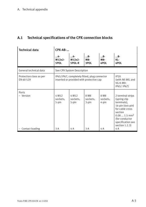
A. Technical appendix
A-3Festo P.BE-CPX-EA-EN en 1105h
A.1 Technical specifications of the CPX connection blocks
Technical data CPX-AB-...
...4-M12x2-5POL
...4-M12x2-5POL-R
...8-M8-3POL
...8-M8-4POL
...8-KL-4POL
General technical data See CPX System Description
Protection class as perEN 60 529
IP65/IP67, completely fitted, plug connectorinserted or provided with protective cap
IP20(with AK-8KL andVG-K-M9:IP65/ IP67)
Ports– Version
– Contact loading
4 M12sockets,5-pin
3 A
4 M12sockets,5-pin
4 A
8 M8sockets,3-pin
3 A
8 M8sockets,4-pin
4 A
2 terminal strips(spring clipterminals),16-pin (4x4-pin)for cable crosssection0.08 ... 1.5 mm2
(for conductorspecification seesection 1.2.3)4 A

A. Technical appendix
A-4 Festo P.BE-CPX-EA-EN en 1105h
Technical data CPX-AB-...
...1-SUB-BU-25POL ...4-HARX2-4POL ...4-M12-8POL
General technical data See CPX System Description
Protection class as per EN 60 529 IP20(with plugSD-SUB-D-ST25:IP65/IP67)
IP65/IP67, completely fitted, plugconnector inserted or provided withprotective cap
Ports– Version
– Contact loading
1 sub-D socket,25-pin
4 A
4 HARAXsockets, 4-pin,connection withinsulation dis-placement tech-nology, for cablecross section0.5 ... 1.0 mm2
(for conductorspecificationsee section 1.2.3)3 A
4 M12 sockets,8-pin, forconnection ZVK
3 A
A.2 Technical specifications of the CPX metal connection blocks
Technical data CPX-M-...
...4-M12x2-5POL ...8-M12x2-5POL
General technical data See CPX System Description
Protection class as perEN 60 529
IP65/IP67, completely fitted, plug connector inserted or providedwith protective cap
Ports– Version– Contact loading
4 M12 sockets, 5-pin4 A
8 M12 sockets, 5-pin4 A

A. Technical appendix
A-5Festo P.BE-CPX-EA-EN en 1105h
A.3 Technical specifications of the CPX input modules
Technical data CPX-4DE CPX-8DE CPX-8DE-D CPX-8NDE
General technical data See CPX System Description
Protection class to EN 60 529 See technical specifications for the connection blockfitted
Operating voltage supply forelectronics/sensors (VEL/SEN)– Nominal voltage– Intrinsic current consumption at 24 V
(internal electronics)
DC 24 V ± 25 %Typ. 15 mA
Digital inputs as per IEC 61131-2 type 2,24 V
4 inputs 8 inputs 8 inputsn-switching
– Version 0 ... 30 V DC, positive logic (PNP) Negativelogic (NPN)
– Logic level: log. 0 / log. 1 ≤ 5 V / ≥ 11 V ≥ 11 V/≤ 5 V
– Response delay at 24 V– Current consumption at 24 V (input
current)– Sensor supply: Voltage drop to
VEL/SEN (reduction of sensor supplyvoltage)
– Reverse polarity protection24 VSEN against 0 VSEN
Can be parameterised, typ. 3 msWith “log. 1”: typ. + 9.3 mA (CPX-8NDE: typ. - 9.3 mA)
Max. 0.7 V
Yes
– Short circuit protection in sensorsupply
Electronic for the complete module(CPX-8DE-D: per channel)
– Response threshold– Characteristic
0.7 A … 2.4 Aslow-blowing
1.0 A … 2.5 Aslow-blowing
0.7 A … 1.9 Aslow-blowing
Galvanic isolation None
Potential difference between 0 V sensorsupply connections and 0 V supply forelectronics/sensors (VEL/SEN)
Not permitted 24 V conn.:notpermitted
Module code [type code] (CPX-specific)Module identification (Handheld)
14DI
28DI
78DI-D
148NDI
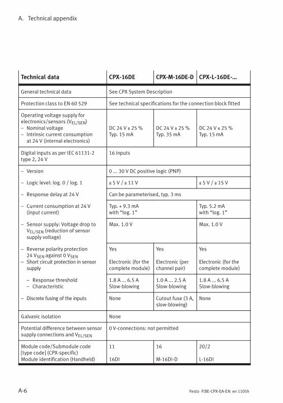
A. Technical appendix
A-6 Festo P.BE-CPX-EA-EN en 1105h
Technical data CPX-16DE CPX-M-16DE-D CPX-L-16DE-…
General technical data See CPX System Description
Protection class to EN 60 529 See technical specifications for the connection block fitted
Operating voltage supply forelectronics/sensors (VEL/SEN)– Nominal voltage– Intrinsic current consumption
at 24 V (internal electronics)
DC 24 V ± 25 %Typ. 15 mA
DC 24 V ± 25 %Typ. 35 mA
DC 24 V ± 25 %Typ. 15 mA
Digital inputs as per IEC 61131-2type 2, 24 V
16 inputs
– Version 0 ... 30 V DC positive logic (PNP)
– Logic level: log. 0 / log. 1 ≤ 5 V / ≥ 11 V ≤ 5 V / ≥ 15 V
– Response delay at 24 V Can be parameterised, typ. 3 ms
– Current consumption at 24 V(input current)
Typ. + 9.3 mAwith “log. 1”
Typ. 5.2 mAwith “log. 1”
– Sensor supply: Voltage drop toVEL/SEN (reduction of sensorsupply voltage)
Max. 1.0 V Max. 1.0 V
– Reverse polarity protection24 VSEN against 0 VSEN
– Short circuit protection in sensorsupply
Yes
Electronic (for thecomplete module)
Yes
Electronic (perchannel pair)
Yes
Electronic (for thecomplete module)
– Response threshold– Characteristic
1.8 A ... 6.5 ASlow-blowing
1.0 A ... 2.5 ASlow-blowing
1.8 A ... 6.5 ASlow-blowing
– Discrete fusing of the inputs None Cutout fuse (3 A,slow-blowing)
None
Galvanic isolation None
Potential difference between sensorsupply connections and VEL/SEN
0 V-connections: not permitted
Module code/Submodule code[type code] (CPX-specific)Module identification (Handheld)
11
16DI
16
M-16DI-D
20/2
L-16DI

A. Technical appendix
A-7Festo P.BE-CPX-EA-EN en 1105h
A.4 Technical specifications of the CPX output modules
Technical data CPX-4DA CPX-8DA CPX-8DA-H
General technical data See CPX System Description
Protection class to EN 60 529 See technical specifications for the connection blockfitted
Operating voltage supply forelectronics/sensors (VEL/SEN)– Nominal voltage DC 24 V ± 25 %
– Intrinsic current consumption at 24 V(internal electronics, all outputs0-signal)
Typ. 16 mA
Load voltage supply for outputs (VOUT)– Nominal voltage– Intrinsic current consumption at 24 V
(internal electronics)– Diagnostic message undervoltage
VOUT (monitoring VOUT, load voltageoutside function range)
DC 24 V ± 25 %Typ. 20 mA
≤ 17 ... 14 V
DC 24 V ± 25 %Typ. 34 mA
≤ 17 ... 14 V
Digital outputs 4 outputs basedon IEC 61131-2type 2, 24 V
8 outputs as perIEC 61131-2,24 V
8 outputs basedon IEC 61131-2type 2, 24 V
– Rated load voltage– Version– Reverse polarity protection
VOUTPositive logic (PNP)Yes
Max. output current– per channel
– per output socket when plug/cableis assigned twice
– per module
Max. 1.0 A (24Wbulb load)2.0 A
4.0 A
Max. 0.5 A (12Wbulb load)1.0 A
4.0 A
Max. 2.1 A(50W bulb load)not permitted
8.4 A

A. Technical appendix
A-8 Festo P.BE-CPX-EA-EN en 1105h
Technical data CPX-8DA-HCPX-8DACPX-4DA
– Short circuit protection
– Discrete fusing of the outputs
Yes (electronic),responsethreshold > 1 A
None
Yes (electronic),responsethreshold > 0.5 A
None
Yes (electronic),responsethreshold seeFig. A/1Cutout fuse (4 A,slow-blowing)
– Voltage drop at output– Output delay with ohmic load
– signal change “0” to “1”– signal change “1” to “0”
– Parallel switching of outputs forincreased performance
≤ 1 V
< 200 μs< 200 μsYes, max. 4 outputs of the samemodule:
≤ 1 V
< 200 μs< 200 μsNot permitted
O0 … O3 O0…O3 / O4…O7
– Protection against reverse voltage– Limiting the inductive switch-off
voltage of connected coils/solenoidvalves
Max. VOUTTyp. -16 V
Galvanic isolation– between the channels– between the operating voltage
supply for the electronics/sensors(VEL/SEN) and the load voltage for theoutputs (VOUT)
NoneYes, with power supply via interlinking block type:– CPX-GE-EV-Z (M18)– CPX-GE-EV-S-7/8-5POL– CPX-GE-EV-Z-7/8-5POL– CPX-M-GE-EV-S-7/8-5POL– CPX-M-GE-EV-Z-7/8-5POL– CPX-GE-EV-Z-7/8-4POL
Isolation Tested with 500 V DC
Module code [type code] (CPX-specific)Module identification (Handheld)
34DO
68DO
178DO-H
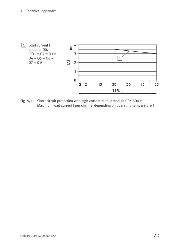
A. Technical appendix
A-9Festo P.BE-CPX-EA-EN en 1105h
1 Load current Iat outlet O0,if O1 = O2 = O3 =O4 = O5 = O6 =O7 = 0 A
Fig. A/1: Short circuit protection with high-current output module CPX-8DA-H:Maximum load current I per channel depending on operating temperature T
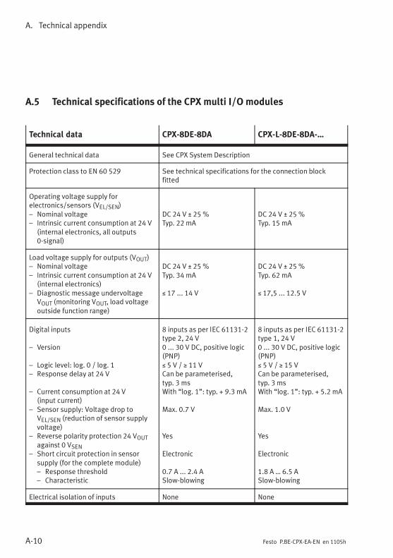
A. Technical appendix
A-10 Festo P.BE-CPX-EA-EN en 1105h
A.5 Technical specifications of the CPX multi I/O modules
Technical data CPX-8DE-8DA CPX-L-8DE-8DA-…
General technical data See CPX System Description
Protection class to EN 60 529 See technical specifications for the connection blockfitted
Operating voltage supply forelectronics/sensors (VEL/SEN)– Nominal voltage– Intrinsic current consumption at 24 V
(internal electronics, all outputs0-signal)
DC 24 V ± 25 %Typ. 22 mA
DC 24 V ± 25 %Typ. 15 mA
Load voltage supply for outputs (VOUT)– Nominal voltage– Intrinsic current consumption at 24 V
(internal electronics)– Diagnostic message undervoltage
VOUT (monitoring VOUT, load voltageoutside function range)
DC 24 V ± 25 %Typ. 34 mA
≤ 17 ... 14 V
DC 24 V ± 25 %Typ. 62 mA
≤ 17,5 ... 12.5 V
Digital inputs
– Version
– Logic level: log. 0 / log. 1– Response delay at 24 V
– Current consumption at 24 V(input current)
– Sensor supply: Voltage drop toVEL/SEN (reduction of sensor supplyvoltage)
– Reverse polarity protection 24 VOUTagainst 0 VSEN
– Short circuit protection in sensorsupply (for the complete module)– Response threshold– Characteristic
8 inputs as per IEC 61131-2type 2, 24 V0 ... 30 V DC, positive logic(PNP)≤ 5 V / ≥ 11 VCan be parameterised,typ. 3 msWith “log. 1”: typ. + 9.3 mA
Max. 0.7 V
Yes
Electronic
0.7 A ... 2.4 ASlow-blowing
8 inputs as per IEC 61131-2type 1, 24 V0 ... 30 V DC, positive logic(PNP)≤ 5 V / ≥ 15 VCan be parameterised,typ. 3 msWith “log. 1”: typ. + 5.2 mA
Max. 1.0 V
Yes
Electronic
1.8 A … 6.5 ASlow-blowing
Electrical isolation of inputs None None

A. Technical appendix
A-11Festo P.BE-CPX-EA-EN en 1105h
Technical data CPX-L-8DE-8DA-…CPX-8DE-8DA
Potential difference between 0 V sensorsupply connections and 0 V supply forelectronics/sensors (VEL/SEN)
Not permitted Not permitted
Digital outputs
– Rated load voltage– Version– Reverse polarity protection– Output current per channel– Short circuit protection
– Voltage drop at output– Output delay with ohmic load
– signal change “0” to “1”– signal change “1” to “0”
– Parallel switching of outputs forincreased performance
– Protection against reverse voltage– Limiting the inductive switch-off
voltage of connected coils/solenoidvalves
8 outputs as perIEC 61131-2, 24 VVOUTPositive logic (PNP)YesMax. 0.5 A (12 W lamp load)Yes (electronic), responsethreshold > 0.5 A≤ 1 V
< 200 μs< 200 μsYes, max. 4 outputs(O0 … O3 or O4 … O7) fromthe same moduleMax. VOUTTyp. -16 V
8 outputs as perIEC 61131-2, 24 VVOUTPositive logic (PNP)YesMax. 0.25 A (6 W lamp load)Yes (electronic), responsethreshold > 0.25 A≤ 1 V
< 200 μs< 200 μsYes, max. 4 outputs(O0 … O3 or O4 … O7) fromthe same moduleMax. VOUTTyp. -18 V
Electrical isolation of the outputs– between the channels– between the operating voltage
supply for the electronics/sensors(VEL/SEN) and the load voltage for theoutputs (VOUT)
NoneYes, with power supply viainterlinking block type:– CPX-GE-EV-Z (M18)– CPX-GE-EV-S-7/8-5POL– CPX-GE-EV-Z-7/8-5POL– CPX-M-GE-EV-S-7/8-5POL– CPX-M-GE-EV-Z-7/8-5POL– CPX-GE-EV-Z-7/8-4POL
NoneNone:The CPX-L multi I/O module
internally connects the contact
rails 0 VEL/SEN and 0 VOUT of the
CPX terminal. This means that
the operating voltage supply for
the electronics/sensors (VEL/SEN)
and the load voltage supply for
the outputs (VOUT) are no longer
electrically isolated
(see section 4.3).
Isolation Tested with 500 V DC –
Module code/Submodule code[type code] (CPX-specific)Module identification (Handheld)
4
8DI/8DO
22/2
L-8DI8DO
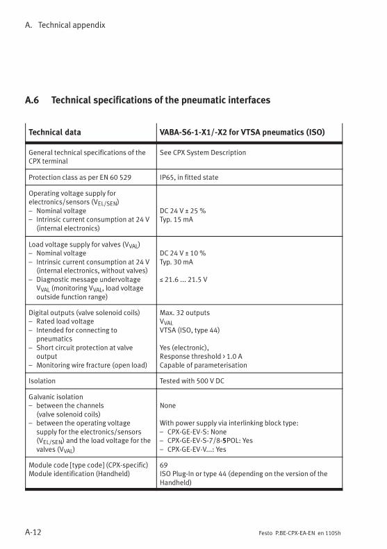
A. Technical appendix
A-12 Festo P.BE-CPX-EA-EN en 1105h
A.6 Technical specifications of the pneumatic interfaces
Technical data VABA-S6-1-X1/-X2 for VTSA pneumatics (ISO)
General technical specifications of theCPX terminal
See CPX System Description
Protection class as per EN 60 529 IP65, in fitted state
Operating voltage supply forelectronics/sensors (VEL/SEN)– Nominal voltage– Intrinsic current consumption at 24 V
(internal electronics)
DC 24 V ± 25 %Typ. 15 mA
Load voltage supply for valves (VVAL)– Nominal voltage– Intrinsic current consumption at 24 V
(internal electronics, without valves)– Diagnostic message undervoltage
VVAL (monitoring VVAL, load voltageoutside function range)
DC 24 V ± 10 %Typ. 30 mA
≤ 21.6 ... 21.5 V
Digital outputs (valve solenoid coils)– Rated load voltage– Intended for connecting to
pneumatics– Short circuit protection at valve
output– Monitoring wire fracture (open load)
Max. 32 outputsVVALVTSA (ISO, type 44)
Yes (electronic),Response threshold > 1.0 ACapable of parameterisation
Isolation Tested with 500 V DC
Galvanic isolation– between the channels
(valve solenoid coils)– between the operating voltage
supply for the electronics/sensors(VEL/SEN) and the load voltage for thevalves (VVAL)
None
With power supply via interlinking block type:– CPX-GE-EV-S: None– CPX-GE-EV-S-7/8-5POL: Yes– CPX-GE-EV-V...: Yes
Module code [type code] (CPX-specific)Module identification (Handheld)
69ISO Plug-In or type 44 (depending on the version of theHandheld)

A. Technical appendix
A-13Festo P.BE-CPX-EA-EN en 1105h
Technical data CPX-GP-03-4.0 CPX-GP-CPA-...
General technical specifications of theCPX terminal
See CPX System Description
Protection class as per EN 60 529 IP65, in fitted state
Operating voltage supply forelectronics/sensors (VEL/SEN)– Nominal voltage– Intrinsic current consumption at 24 V
(internal electronics)
DC 24 V ± 25 %Typ. 15 mA
Load voltage supply for valves (VVAL)– Nominal voltage– Intrinsic current consumption at 24 V
(internal electronics, without valves)– Diagnostic message undervoltage
VVAL (monitoring VVAL, load voltageoutside function range)
DC 24 V ± 10 %Typ. 30 mA
≤ 21.6 ... 21.5 V
DC 24 V +10 %/-15%Typ. 30 mA
≤ 19.8 ... 19.6 V
Digital outputs (valve solenoid coils)– Rated load voltage– Intended for connecting to
pneumatics– Short circuit protection at valve
output– Monitoring wire fracture (open load)
Max. 26 outputsVVALMidi/Maxi (type 03)
Yes (electronic),response threshold > 1.0 ANo
Max. 22 outputsVVALCPA (type 12)
Yes (electronic),response threshold > 1.0 ACapable of parameterisation
Isolation Tested with 500 V DC
Galvanic isolation– between the channels
(valve solenoid coils)– between the operating voltage
supply for the electronics/sensors(VEL/SEN) and the load voltage for thevalves (VVAL)
None
With power supply via interlinking block type:– CPX-GE-EV-S: None– CPX-GE-EV-S-7/8-5POL: Yes– CPX-GE-EV-V...: Yes
Module code [type code] (CPX-specific)Module identification (Handheld)
67TYPE3
66CPA10/14
A. Technical appendix
A-14 Festo P.BE-CPX-EA-EN en 1105h

Internal structure and circuitry examples
B-1Festo P.BE-CPX-EA-EN en 1105h
Appendix B
Internal structure and circuitry examples
B. Internal structure and circuitry examples
B-2 Festo P.BE-CPX-EA-EN en 1105h
Contents
B. Internal structure and circuitry examples B-1. . . . . . . . . . . . . . . . . . . . . . . . . .
B.1 Internal structure of the CPX I/O modules B-3. . . . . . . . . . . . . . . . . . . . . . . . . . .
B.2 Circuitry examples for CPX inputs and outputs B-8. . . . . . . . . . . . . . . . . . . . . . .
B.2.1 Circuitry examples for PNP inputs B-8. . . . . . . . . . . . . . . . . . . . . . . . . .
B.2.2 Circuitry examples for PNP outputs B-8. . . . . . . . . . . . . . . . . . . . . . . . .
B.2.3 Circuitry examples for NPN inputs B-9. . . . . . . . . . . . . . . . . . . . . . . . . .
B.2.4 Circuitry example with DUO cable B-10. . . . . . . . . . . . . . . . . . . . . . . . . .
B.2.5 Circuitry example with DNCV B-11. . . . . . . . . . . . . . . . . . . . . . . . . . . . . .
B.3 Accessories (CPX terminal) B-12. . . . . . . . . . . . . . . . . . . . . . . . . . . . . . . . . . . . . . .

B. Internal structure and circuitry examples
B-3Festo P.BE-CPX-EA-EN en 1105h
B.1 Internal structure of the CPX I/O modules
Internal structure of CPX-4DE, CPX-8DE andCPX-16DE
1 Diagnostics
2 Ix = Input x
3 Monitoring/switchingoff the sensor supply
4 Logic identifier Ix
5 Red moduleError LED
6 Green LED Ix
7 Connections on theconnection block(FE not provided onall connection blocks)
1
2
3
4
5
24 VSEN
Ix
0 VSEN
FE
24 V ± 25% (VEL/SEN)
0 V (VEL/SEN)
6
7
Fig. B/1: Internal structure of CPX-4DE, CPX-8DE and CPX-16DE
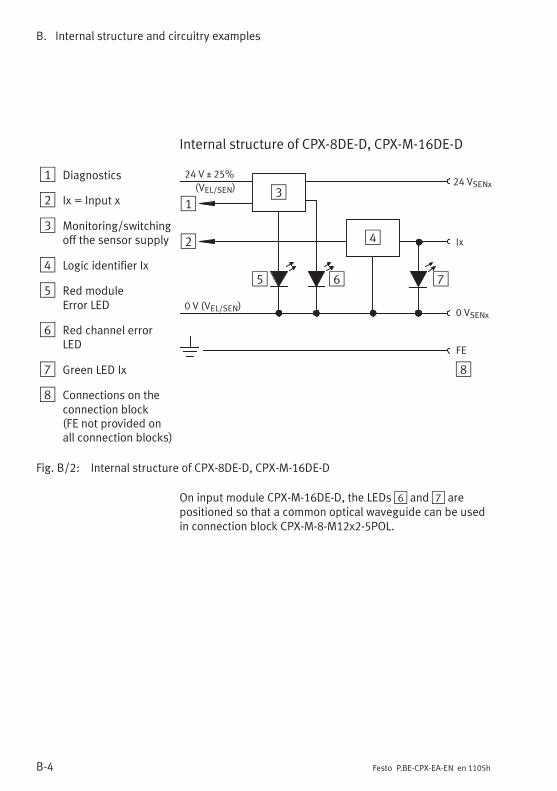
B. Internal structure and circuitry examples
B-4 Festo P.BE-CPX-EA-EN en 1105h
Internal structure of CPX-8DE-D, CPX-M-16DE-D
1 Diagnostics
2 Ix = Input x
3 Monitoring/switchingoff the sensor supply
4 Logic identifier Ix
5 Red moduleError LED
6 Red channel errorLED
7 Green LED Ix
8 Connections on theconnection block(FE not provided onall connection blocks)
24 VSENx
1
2
3
4
5
Ix
0 VSENx
FE
24 V ± 25%
0 V (VEL/SEN)
6 7
8
(VEL/SEN)
Fig. B/2: Internal structure of CPX-8DE-D, CPX-M-16DE-D
On input module CPX-M-16DE-D, the LEDs6 and7 arepositioned so that a common optical waveguide can be usedin connection block CPX-M-8-M12x2-5POL.
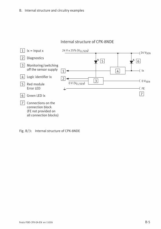
B. Internal structure and circuitry examples
B-5Festo P.BE-CPX-EA-EN en 1105h
Internal structure of CPX-8NDE
1 Ix = Input x
2 Diagnostics
3 Monitoring/switchingoff the sensor supply
4 Logic identifier Ix
5 Red moduleError LED
6 Green LED Ix
7 Connections on theconnection block(FE not provided onall connection blocks)
1
23
4
5
24 VSEN
Ix
0 VSEN
FE
24 V ± 25% (VEL/SEN)
0 V (VEL/SEN)
6
7
Fig. B/3: Internal structure of CPX-8NDE

B. Internal structure and circuitry examples
B-6 Festo P.BE-CPX-EA-EN en 1105h
Internal structure of CPX-4DA, CPX-8DA andCPX-8DA-H
1 Ox = Output x
2 Diagnostics– Output status– Overload– Undervoltage
3 Output driver
4 Monitoring
5 Red moduleError LED
6 Red channelError LED Ox
7 Yellow LED Ox
8 Limiting inductivevoltage peaks
9 Connections on theconnection block(FE not provided onall connection blocks)
1
2
3
5
Ox
0 VOUT
FE
7
6
0 V (VOUT)
24 V ± 25% (VOUT)
4
9
8
Fig. B/4: Internal structure of CPX-4DA, CPX-8DA and CPX-8DA-H

B. Internal structure and circuitry examples
B-7Festo P.BE-CPX-EA-EN en 1105h
Internal structure of CPX-8DE-8DA
1 Diagnostics
2 Ix = Input x
3 Ox = Output x
4 Monitoring/switchingoff the sensor supply
5 Logic identifier Ix
6 Output driver
7 Monitoring/switchingoff the output
8 Red moduleError LED
9 Yellow LED Ox
aJ Green LED Ix
aA Limiting inductivevoltage peaks
aB Connections on theconnection block(FE not provided onall connection blocks)
1
2
3
4
5
24 VSEN
Ix
0 VSEN
24 V ± 25% (VEL/SEN)
0 V (VEL/SEN)
1
Ox
0 VOUT
FE
0 V (VOUT)
24 V ± 25% (VOUT)
6
8
7
9
aJ
aA
aB
Fig. B/5: Internal structure of CPX-8DE-8DA

B. Internal structure and circuitry examples
B-8 Festo P.BE-CPX-EA-EN en 1105h
B.2 Circuitry examples for CPX inputs and outputs
B.2.1 Circuitry examples for PNP inputs
1 Three-wire sensor(positive logic)
2 Two-wire sensor(positive logic)
3 Contact
Ix = Input x
1
2
3
24 V
0 V
Ix
24 V
Ix
24 V
Ix
Fig. B/6: Circuitry examples for PNP inputs
B.2.2 Circuitry examples for PNP outputs
1 Example 1:Lamp
2 Example 2:Relay
Ox = Output x
1
2
0 V
Ox
Ox
0 V
Fig. B/7: Circuitry examples for PNP outputs

B. Internal structure and circuitry examples
B-9Festo P.BE-CPX-EA-EN en 1105h
B.2.3 Circuitry examples for NPN inputs
1 Three-wire sensor(negative logic)
2 Two-wire sensor(negative logic)
3 Contact
Ix = Input x
1
2
3
24 V
0 V
Ix
Ix
0 V
Ix
0 V
Fig. B/8: Circuitry examples for NPN inputs

B. Internal structure and circuitry examples
B-10 Festo P.BE-CPX-EA-EN en 1105h
B.2.4 Circuitry example with DUO cable
Connection only possible with connection blockCPX-AB-4-M12x2-5POL (-R), CPX-M-4-M12x2-5POL orCPX-M-8-M12x2-5POL.
1 CPX-4DE:Sockets X1, X3CPX-8DE (-D):Sockets X1 ... X4CPX-M-16DE-D:Sockets X1 ... X8
Pin allocation1: 24 V2: Ix+13: 0 V4: Ix5: FE
2 Sensor 1 (Ix)
3 2-way distributor(T-piece, e.g. FestoDuo cable;only 4-pin)
4 Sensor 2 (Ix+1)
Ix = Input x(x = 0, 2, 4, 6)
1 2
3
4
2
3
1
5
4
Fig. B/9: Circuitry examples for DUO cable with connection blockCPX-AB-4-M12x2-5POL (-R), CPX-M-4-M12x2-5POL or CPX-M-8-M12x2-5POL
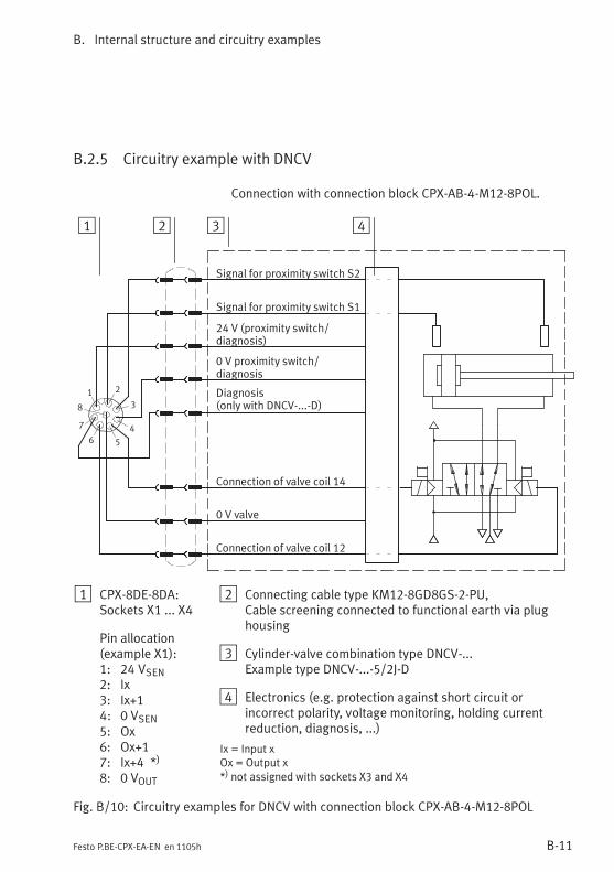
B. Internal structure and circuitry examples
B-11Festo P.BE-CPX-EA-EN en 1105h
B.2.5 Circuitry example with DNCV
Connection with connection block CPX-AB-4-M12-8POL.
1 2 3 4
2
3
1
5
4
8
6
7
Signal for proximity switch S2
Signal for proximity switch S1
24 V (proximity switch/diagnosis)
0 V proximity switch/diagnosis
Connection of valve coil 12
Connection of valve coil 14
0 V valve
Diagnosis(only with DNCV-...-D)
1 CPX-8DE-8DA:Sockets X1 ... X4
Pin allocation(example X1):1: 24 VSEN2: Ix3: Ix+14: 0 VSEN5: Ox6: Ox+17: Ix+4 *)
8: 0 VOUT
2 Connecting cable type KM12-8GD8GS-2-PU,Cable screening connected to functional earth via plughousing
3 Cylinder-valve combination type DNCV-...Example type DNCV-...-5/2J-D
4 Electronics (e.g. protection against short circuit orincorrect polarity, voltage monitoring, holding currentreduction, diagnosis, ...)
Ix = Input xOx = Output x*) not assigned with sockets X3 and X4
Fig. B/10: Circuitry examples for DNCV with connection block CPX-AB-4-M12-8POL

B. Internal structure and circuitry examples
B-12 Festo P.BE-CPX-EA-EN en 1105h
B.3 Accessories (CPX terminal)
} www.festo.com/catalogue

Index
C-1Festo P.BE-CPX-EA-EN en 1105h
Appendix C
Index
C. Index
C-2 Festo P.BE-CPX-EA-EN en 1105h
Contents
C. Index C-1. . . . . . . . . . . . . . . . . . . . . . . . . . . . . . . . . . . . . . . . . . . . . . . . . . . . . . . . .

C. Index
C-3Festo P.BE-CPX-EA-EN en 1105h
A
Abbreviations, (product-specific) XV. . . . . . . . . . . . . . . . . . . .
Approvals VII. . . . . . . . . . . . . . . . . . . . . . . . . . . . . . . . . . . . . . .
Areas of application VII. . . . . . . . . . . . . . . . . . . . . . . . . . . . . . .
B
Behaviour after short circuit 2-33, 3-23, 4-11. . . . . . . . . . . . .
C
Circuitry examplesDNCV B-11. . . . . . . . . . . . . . . . . . . . . . . . . . . . . . . . . . . . . . . .DUO cable B-10. . . . . . . . . . . . . . . . . . . . . . . . . . . . . . . . . . . .NPN inputs B-9. . . . . . . . . . . . . . . . . . . . . . . . . . . . . . . . . . . .PNP inputs B-8. . . . . . . . . . . . . . . . . . . . . . . . . . . . . . . . . . . .PNP outputs B-8. . . . . . . . . . . . . . . . . . . . . . . . . . . . . . . . . . .
Connection blocksCombinations with I/O modules 1-10. . . . . . . . . . . . . . . . . .Connecting the cables and plugs 1-13. . . . . . . . . . . . . . . . .Metal design 1-7, 1-9, 1-12. . . . . . . . . . . . . . . . . . . . . . . . . . .Overview 1-3, 1-4. . . . . . . . . . . . . . . . . . . . . . . . . . . . . . . . . .
Connection technology 1-4. . . . . . . . . . . . . . . . . . . . . . . . . . . .
Contact loading A-3, A-4. . . . . . . . . . . . . . . . . . . . . . . . . . . . . .
CPX I/O modules, Overview XII. . . . . . . . . . . . . . . . . . . . . . . .
CPX pneumatic interfaces, Overview 5-4. . . . . . . . . . . . . . . . .
CPX terminal, Structure XI. . . . . . . . . . . . . . . . . . . . . . . . . . . . .
CPX-16DE 2-26. . . . . . . . . . . . . . . . . . . . . . . . . . . . . . . . . . . . . .Technical data A-6. . . . . . . . . . . . . . . . . . . . . . . . . . . . . . . . . .
CPX-4DA 3-5. . . . . . . . . . . . . . . . . . . . . . . . . . . . . . . . . . . . . . . .Internal structure B-6. . . . . . . . . . . . . . . . . . . . . . . . . . . . . . .Technical data A-7. . . . . . . . . . . . . . . . . . . . . . . . . . . . . . . . . .
CPX-4DE 2-6. . . . . . . . . . . . . . . . . . . . . . . . . . . . . . . . . . . . . . . .Internal structure B-3. . . . . . . . . . . . . . . . . . . . . . . . . . . . . . .Technical data A-5. . . . . . . . . . . . . . . . . . . . . . . . . . . . . . . . . .

C. Index
C-4 Festo P.BE-CPX-EA-EN en 1105h
CPX-8DA 3-11. . . . . . . . . . . . . . . . . . . . . . . . . . . . . . . . . . . . . . .Internal structure B-6. . . . . . . . . . . . . . . . . . . . . . . . . . . . . . .Technical data A-7. . . . . . . . . . . . . . . . . . . . . . . . . . . . . . . . . .
CPX-8DA-H 3-17. . . . . . . . . . . . . . . . . . . . . . . . . . . . . . . . . . . . .Internal structure B-6. . . . . . . . . . . . . . . . . . . . . . . . . . . . . . .Technical data A-7, A-9. . . . . . . . . . . . . . . . . . . . . . . . . . . . . .
CPX-8DE 2-11. . . . . . . . . . . . . . . . . . . . . . . . . . . . . . . . . . . . . . .Internal structure B-3. . . . . . . . . . . . . . . . . . . . . . . . . . . . . . .Technical data A-5. . . . . . . . . . . . . . . . . . . . . . . . . . . . . . . . . .
CPX-8DE-8DA 4-5. . . . . . . . . . . . . . . . . . . . . . . . . . . . . . . . . . . .Internal structure B-7. . . . . . . . . . . . . . . . . . . . . . . . . . . . . . .Technical data A-10. . . . . . . . . . . . . . . . . . . . . . . . . . . . . . . . .
CPX-8DE-D 2-16. . . . . . . . . . . . . . . . . . . . . . . . . . . . . . . . . . . . .Internal structure B-4. . . . . . . . . . . . . . . . . . . . . . . . . . . . . . .Technical data A-5. . . . . . . . . . . . . . . . . . . . . . . . . . . . . . . . . .
CPX-8NDE 2-21. . . . . . . . . . . . . . . . . . . . . . . . . . . . . . . . . . . . . .Internal structure B-5. . . . . . . . . . . . . . . . . . . . . . . . . . . . . . .
CPX-AB-1-SUB-BU-25POLConnecting the cables and plugs 1-19. . . . . . . . . . . . . . . . .Technical data A-4. . . . . . . . . . . . . . . . . . . . . . . . . . . . . . . . . .
CPX-AB-4-HARX2-4POLConnecting the cables and plugs 1-20. . . . . . . . . . . . . . . . .Technical data A-4. . . . . . . . . . . . . . . . . . . . . . . . . . . . . . . . . .
CPX-AB-4-M12-8POLConnecting the cables and plugs 1-22. . . . . . . . . . . . . . . . .Technical data A-4. . . . . . . . . . . . . . . . . . . . . . . . . . . . . . . . . .
CPX-AB-4-M12x2-5POL, Technical data A-3. . . . . . . . . . . . . . .
CPX-AB-4-M12x2-5POL (-R),Connecting the cables and plugs 1-14. . . . . . . . . . . . . . . . .
CPX-AB-4-M12x2-5POL-R, Technical data A-3. . . . . . . . . . . . . .
CPX-AB-8-KL-4POLConnecting the cables and plugs 1-17. . . . . . . . . . . . . . . . .Technical data A-3. . . . . . . . . . . . . . . . . . . . . . . . . . . . . . . . . .
CPX-AB-8-M8-3POLConnecting the cables and plugs 1-17. . . . . . . . . . . . . . . . .Technical data A-3. . . . . . . . . . . . . . . . . . . . . . . . . . . . . . . . . .
C. Index
C-5Festo P.BE-CPX-EA-EN en 1105h
CPX-AB-8-M8-4POLConnecting the cables and plugs 1-17. . . . . . . . . . . . . . . . .Technical data A-3. . . . . . . . . . . . . . . . . . . . . . . . . . . . . . . . . .
CPX-GP-03-4.0DIL switch 5-13. . . . . . . . . . . . . . . . . . . . . . . . . . . . . . . . . . . .Technical data A-13. . . . . . . . . . . . . . . . . . . . . . . . . . . . . . . . .
CPX-GP-CPA-...DIL switch 5-13. . . . . . . . . . . . . . . . . . . . . . . . . . . . . . . . . . . .Technical data A-13. . . . . . . . . . . . . . . . . . . . . . . . . . . . . . . . .
CPX-GP-ISO, DIL switch 5-13. . . . . . . . . . . . . . . . . . . . . . . . . . .
CPX-L-16DE 2-31. . . . . . . . . . . . . . . . . . . . . . . . . . . . . . . . . . . . .Technical data A-6. . . . . . . . . . . . . . . . . . . . . . . . . . . . . . . . . .
CPX-L-8DE-8DA 4-9. . . . . . . . . . . . . . . . . . . . . . . . . . . . . . . . . . .Technical data A-10. . . . . . . . . . . . . . . . . . . . . . . . . . . . . . . . .
CPX-M-16DE-D 2-29. . . . . . . . . . . . . . . . . . . . . . . . . . . . . . . . . .Technical data A-6. . . . . . . . . . . . . . . . . . . . . . . . . . . . . . . . . .
CPX-M-4-M12x2-5POLConnecting the cables and plugs 1-14. . . . . . . . . . . . . . . . .Technical data A-4. . . . . . . . . . . . . . . . . . . . . . . . . . . . . . . . . .
CPX-M-8-M12x2-5POLAssembly instructions 1-27. . . . . . . . . . . . . . . . . . . . . . . . . .Connecting the cables and plugs 1-14. . . . . . . . . . . . . . . . .Technical data A-4. . . . . . . . . . . . . . . . . . . . . . . . . . . . . . . . . .
D
Diagnosis- via the fieldbus/network XIV. . . . . . . . . . . . . . . . . . . . . . . .Input modules 2-36. . . . . . . . . . . . . . . . . . . . . . . . . . . . . . . .Multi I/O modules 4-16. . . . . . . . . . . . . . . . . . . . . . . . . . . . .Output modules 3-25. . . . . . . . . . . . . . . . . . . . . . . . . . . . . . .Pneumatic interfaces 5-20. . . . . . . . . . . . . . . . . . . . . . . . . . .
Display and connecting elementsI/O modules 1-8. . . . . . . . . . . . . . . . . . . . . . . . . . . . . . . . . . .Pneumatic interfaces 5-5. . . . . . . . . . . . . . . . . . . . . . . . . . . .
C. Index
C-6 Festo P.BE-CPX-EA-EN en 1105h
E
Error messagesInput modules 2-36. . . . . . . . . . . . . . . . . . . . . . . . . . . . . . . .Multi I/O modules 4-16. . . . . . . . . . . . . . . . . . . . . . . . . . . . .Output modules 3-26. . . . . . . . . . . . . . . . . . . . . . . . . . . . . . .Pneumatic interfaces 5-21. . . . . . . . . . . . . . . . . . . . . . . . . . .
F
Fail Safe parameterisation 3-23, 4-14, 5-18. . . . . . . . . . . . . . .
Force 2-35, 3-24, 4-15, 5-19. . . . . . . . . . . . . . . . . . . . . . . . . . . .
I
I/O modulesAssembly 1-24. . . . . . . . . . . . . . . . . . . . . . . . . . . . . . . . . . . .Combinations with connection blocks 1-10. . . . . . . . . . . . . .Components 1-3. . . . . . . . . . . . . . . . . . . . . . . . . . . . . . . . . . .Overview XII. . . . . . . . . . . . . . . . . . . . . . . . . . . . . . . . . . . . . .
Idle mode 3-24, 4-14, 5-19. . . . . . . . . . . . . . . . . . . . . . . . . . . .
Input debounce time 2-33, 4-12. . . . . . . . . . . . . . . . . . . . . . . .
Input modulesDiagnosis 2-36. . . . . . . . . . . . . . . . . . . . . . . . . . . . . . . . . . . .Error messages 2-36. . . . . . . . . . . . . . . . . . . . . . . . . . . . . . . .Function 2-3. . . . . . . . . . . . . . . . . . . . . . . . . . . . . . . . . . . . . .Installation 2-5. . . . . . . . . . . . . . . . . . . . . . . . . . . . . . . . . . . .Instructions on commissioning 2-32. . . . . . . . . . . . . . . . . . .LED display 2-38. . . . . . . . . . . . . . . . . . . . . . . . . . . . . . . . . . .Power supply 2-5. . . . . . . . . . . . . . . . . . . . . . . . . . . . . . . . . .Short circuit/overload 2-40, 2-41. . . . . . . . . . . . . . . . . . . . .
Instructions on commissioningInput modules 2-32. . . . . . . . . . . . . . . . . . . . . . . . . . . . . . . .Multi I/O modules 4-10. . . . . . . . . . . . . . . . . . . . . . . . . . . . .Output modules 3-22. . . . . . . . . . . . . . . . . . . . . . . . . . . . . . .Pneumatic interfaces 5-16. . . . . . . . . . . . . . . . . . . . . . . . . . .
Intended use VI. . . . . . . . . . . . . . . . . . . . . . . . . . . . . . . . . . . . .

C. Index
C-7Festo P.BE-CPX-EA-EN en 1105h
Interlinking block 1-3. . . . . . . . . . . . . . . . . . . . . . . . . . . . . . . . .
Internal structureCPX I/O modules B-3. . . . . . . . . . . . . . . . . . . . . . . . . . . . . . .CPX-M-16DE-D B-4. . . . . . . . . . . . . . . . . . . . . . . . . . . . . . . . .
L
LED display- on the connection blocks 1-8, 1-9. . . . . . . . . . . . . . . . . . . .Input modules 2-38. . . . . . . . . . . . . . . . . . . . . . . . . . . . . . . .Multi I/O modules 4-18. . . . . . . . . . . . . . . . . . . . . . . . . . . . .Output modules 3-27. . . . . . . . . . . . . . . . . . . . . . . . . . . . . . .Pneumatic interfaces 5-8, 5-22. . . . . . . . . . . . . . . . . . . . . . .
M
Module parametersBehaviour after short circuit 2-33, 3-23, 4-11. . . . . . . . . . .Channel-specific moduleparameters 2-35, 3-24, 4-13, 4-14, 4-15, 5-18, 5-19. . . .
Input debounce time 2-33, 4-12. . . . . . . . . . . . . . . . . . . . . .Monitoring the CPX module 2-32, 3-22, 4-10, 5-17. . . . . . . .Signal extension time 2-34, 4-13. . . . . . . . . . . . . . . . . . . . . .
Monitoring the CPX module 2-32, 3-22, 4-10, 5-17. . . . . . . . . .
Multi I/O modulesDiagnosis 4-16. . . . . . . . . . . . . . . . . . . . . . . . . . . . . . . . . . . .Error messages 4-16. . . . . . . . . . . . . . . . . . . . . . . . . . . . . . . .Function 4-3. . . . . . . . . . . . . . . . . . . . . . . . . . . . . . . . . . . . . .Installation 4-4. . . . . . . . . . . . . . . . . . . . . . . . . . . . . . . . . . . .Instructions on commissioning 4-10. . . . . . . . . . . . . . . . . . .LED display 4-18. . . . . . . . . . . . . . . . . . . . . . . . . . . . . . . . . . .Power supply 4-4. . . . . . . . . . . . . . . . . . . . . . . . . . . . . . . . . .Short circuit/overload 4-20. . . . . . . . . . . . . . . . . . . . . . . . . .
N
Notes on the use of this manual X. . . . . . . . . . . . . . . . . . . . . . .

C. Index
C-8 Festo P.BE-CPX-EA-EN en 1105h
O
Output modulesDiagnosis 3-25. . . . . . . . . . . . . . . . . . . . . . . . . . . . . . . . . . . .Error messages 3-26. . . . . . . . . . . . . . . . . . . . . . . . . . . . . . . .Function 3-3. . . . . . . . . . . . . . . . . . . . . . . . . . . . . . . . . . . . . .Installation 3-4. . . . . . . . . . . . . . . . . . . . . . . . . . . . . . . . . . . .Instructions on commissioning 3-22. . . . . . . . . . . . . . . . . . .LED display 3-27. . . . . . . . . . . . . . . . . . . . . . . . . . . . . . . . . . .Power supply 3-4. . . . . . . . . . . . . . . . . . . . . . . . . . . . . . . . . .Short circuit/overload 3-28. . . . . . . . . . . . . . . . . . . . . . . . . .
P
Pictograms IX. . . . . . . . . . . . . . . . . . . . . . . . . . . . . . . . . . . . . . .
Pin assignmentCPX-16DE 2-26 - 2-29. . . . . . . . . . . . . . . . . . . . . . . . . . . . . . .CPX-4DA 3-5 - 3-9. . . . . . . . . . . . . . . . . . . . . . . . . . . . . . . . . .CPX-4DE 2-6 - 2-10. . . . . . . . . . . . . . . . . . . . . . . . . . . . . . . . .CPX-8DA 3-11 - 3-16. . . . . . . . . . . . . . . . . . . . . . . . . . . . . . . .CPX-8DA-H 3-18 - 3-21. . . . . . . . . . . . . . . . . . . . . . . . . . . . . .CPX-8DE 2-11 - 2-15. . . . . . . . . . . . . . . . . . . . . . . . . . . . . . . .CPX-8DE-8DA 4-5 - 4-7. . . . . . . . . . . . . . . . . . . . . . . . . . . . . .CPX-8DE-D 2-16 - 2-20. . . . . . . . . . . . . . . . . . . . . . . . . . . . . .CPX-8NDE 2-21 - 2-25. . . . . . . . . . . . . . . . . . . . . . . . . . . . . . .CPX-L-16DE 2-31. . . . . . . . . . . . . . . . . . . . . . . . . . . . . . . . . . .CPX-L-8DE-8DA 4-9. . . . . . . . . . . . . . . . . . . . . . . . . . . . . . . . .CPX-M-16DE-D 2-29. . . . . . . . . . . . . . . . . . . . . . . . . . . . . . . .
Pneumatic interfacesAssembly 5-9. . . . . . . . . . . . . . . . . . . . . . . . . . . . . . . . . . . . .Diagnosis 5-20. . . . . . . . . . . . . . . . . . . . . . . . . . . . . . . . . . . .DIL switch 5-10. . . . . . . . . . . . . . . . . . . . . . . . . . . . . . . . . . . .Error messages 5-21. . . . . . . . . . . . . . . . . . . . . . . . . . . . . . . .Function 5-3. . . . . . . . . . . . . . . . . . . . . . . . . . . . . . . . . . . . . .Installation 5-15. . . . . . . . . . . . . . . . . . . . . . . . . . . . . . . . . . .Instructions on commissioning 5-16. . . . . . . . . . . . . . . . . . .LED display 5-22. . . . . . . . . . . . . . . . . . . . . . . . . . . . . . . . . . .Power supply 5-15. . . . . . . . . . . . . . . . . . . . . . . . . . . . . . . . .
Power supply 2-5, 3-4, 4-4, 5-15. . . . . . . . . . . . . . . . . . . . . . . .
Protection class 1-19, A-3, A-4, A-12, A-13 - A-24. . . . . . . . . .

C. Index
C-9Festo P.BE-CPX-EA-EN en 1105h
S
Screening plate- connect 1-15, 1-22. . . . . . . . . . . . . . . . . . . . . . . . . . . . . . . .- fitting 1-28. . . . . . . . . . . . . . . . . . . . . . . . . . . . . . . . . . . . . . .
Service VII. . . . . . . . . . . . . . . . . . . . . . . . . . . . . . . . . . . . . . . . .
Short circuit/overload 2-40, 2-41, 3-28, 4-20. . . . . . . . . . . . . .CPX-8DA-H A-9. . . . . . . . . . . . . . . . . . . . . . . . . . . . . . . . . . . .
Signal extension time 2-34, 2-35, 4-13. . . . . . . . . . . . . . . . . . .
T
Target group VII. . . . . . . . . . . . . . . . . . . . . . . . . . . . . . . . . . . . .
Technical dataCPX connection blocks A-3. . . . . . . . . . . . . . . . . . . . . . . . . . .CPX metal connection blocks A-4. . . . . . . . . . . . . . . . . . . . . .Input modules A-5. . . . . . . . . . . . . . . . . . . . . . . . . . . . . . . . .Multi I/O modules A-10. . . . . . . . . . . . . . . . . . . . . . . . . . . . .Output modules A-7. . . . . . . . . . . . . . . . . . . . . . . . . . . . . . . .Pneumatic interfaces A-12. . . . . . . . . . . . . . . . . . . . . . . . . . .
Text designations IX. . . . . . . . . . . . . . . . . . . . . . . . . . . . . . . . . .
U
User instructions VIII. . . . . . . . . . . . . . . . . . . . . . . . . . . . . . . . .
V
VABA-S6-1-X1/-X2, Technical data A-12. . . . . . . . . . . . . . . . . .
W
Wire break monitoring 5-18. . . . . . . . . . . . . . . . . . . . . . . . . . . .

C. Index
C-10 Festo P.BE-CPX-EA-EN en 1105h