data distribution system by university of the …mmillecan/thesis.pdf · a thesis submitted in...
TRANSCRIPT

DATA DISTRIBUTION SYSTEM
by
Pulane Millicent Molebale
A thesis submitted in partial fulfillment of the requirements for the degree of
Bachelor of Science (Honours) in Computer Science
University of the Western Cape
2009
Date: November 8, 2009

University of Western Cape
Abstract
DATA DISTRIBUTION SYSTEM
by Pulane Millicent Molebale
Supervisor: Mr. James Connan Department of Computer Science
ABSTRACT
The objective of this project was to design a data distributed system that would serve as a
platform for various systems. In my project the application will be illustrated by the use of
a point of sale system (POS) i.e. a Sell of stock database of which the sales assistant will
use to make sales transactions, Site office database which will be used by the supervisor
for viewing sales and adding new stock to the database, and a Head office database which
will be used as a form of backup for the system and will be used by the manager for
adding prices to the stock that the supervisor added. This would enable administrative
users to make business decisions.

TABLE OF CONTENTS
Table of Contents ....................................................................................................... i
List of Tables ............................................................................................................ iii
List of figures ........................................................................................................... iv
Acknowledgments .................................................................................................... v
Glossary ................................................................................................................... vi
Chapter 1 ......................................................................................................................... 1 Sketching the background ................................................................................................................... 1
1.1 Introduction ...................................................................................................................... 1
Chapter 2 ......................................................................................................................... 2 User Requirement DOCUMENT ........................................................................................................... 2
2.1 Introduction ...................................................................................................................... 2 2.2 User’s view of the problem .............................................................................................. 2 2.3 What is expected from a software solution? ...................................................................... 2 2.4 What it is not expected from a software ......................................................................... 3 2.5 Summary ........................................................................................................................... 3
Chapter 3 ......................................................................................................................... 5 Requirement Analysis document......................................................................................................... 5
3.1 Introduction ...................................................................................................................... 5 3.2 Challenges to be encountered and possible ways to overcome them .......................... 5 3.3 The Model to be used .......................................................................................................... 6 3.4 Technologies to be used ...................................................................................................... 6 3.5 Conclusion ............................................................................................................................ 6
Chapter 4 ......................................................................................................................... 7 User Interface Specification ................................................................................................................. 7
4.1 Introduction ...................................................................................................................... 7 4.2 Description of the complete user interface .................................................................... 7
4.2.1 Login page ............................................................................................................... 7 4.2.2 The main page ........................................................................................................ 8 4.2.3 Sales page ............................................................................................................... 9 4.2.4 view sale page ...................................................................................................... 10
4.3 How the User Interface behaves ................................................................................... 12 4.4 How the user interacts with the system........................................................................ 14
4.4.1 How the student interacts with the system ........................................................ 14 4.4.2 How the user in the site office interacts with the system ................................. 16 4.4.3 How the user in the head office interacts with the system ............................... 18

ii
4.5 Summary ......................................................................................................................... 19
Chapter 5 ....................................................................................................................... 20 Object Oriented Analysis (OOA) or High Level Design ...................................................................... 20
5.1 Introduction .................................................................................................................... 20 5.2 Data Dictionary ............................................................................................................... 20
5.2.1 Selling Terminal in the Sell of stock database objects ........................................ 20 5.2.2 Site office object ................................................................................................... 21 5.2.3 head office Object ................................................................................................ 21
5.3 Class Diagram ................................................................................................................. 22 5.4 Conclusion ...................................................................................................................... 23
Chapter 6 ....................................................................................................................... 24 Object Oriented Design (OOD) or Lower Level Design ..................................................................... 24
6.1 Introduction .................................................................................................................... 24 6.2 Inner Details of Class Attributes and Methods ............................................................. 24 6.3 State Diagram ................................................................................................................. 24 6.4 Pseudo Code ................................................................................................................... 26 6.3 Conclusion ...................................................................................................................... 28
Chapter 7 ....................................................................................................................... 29 System Testing .................................................................................................................................... 29
8.1 Introduction .................................................................................................................... 29 8.2 Testing the user interface .............................................................................................. 29
Functionality testing ............................................................................................................ 30 Usability testing ................................................................................................................... 33
8.2 Compatibility testing ...................................................................................................... 35
Chapter 8 ....................................................................................................................... 37 User Guide .......................................................................................................................................... 37
8.2 Conclusion ...................................................................................................................... 42
Bibliography ........................................................................................................... 45
Appendices ............................................................................................................. 46 APPENDIX A ................................................................................................................................... 46
System Testing Questionnaire ................................................................................................. 46 APPENDIX B ................................................................................................................................... 50
CODE DOCUMENTATION ......................................................................................................... 50 Summary .............................................................................................................................. 50

iii
LIST OF TABLES
Number Page Table 1: Selling terminal object __________________________________________________________ 21 Table 2: Site office object ______________________________________________________________ 21 Table 3: Head office object _____________________________________________________________ 21 Table 4: Participants Details ____________________________________________________________ 29

iv
LIST OF FIGURES
Number Page Figure 1: Diagram that illustrate the architecture of the system ................................................................. 4 Figure 2: Login Page ....................................................................................................................................... 8 Figure 3: Main Page ....................................................................................................................................... 9 Figure 4: Sales Page ........................................................................................................................................ 9 Figure 5: Viewing Sale Page ......................................................................................................................... 10 Figure 6: Stock Page ..................................................................................................................................... 11 Figure 7: Stock Page for the manager ......................................................................................................... 12 Figure 8: Use case diagram .......................................................................................................................... 13 Figure 9: Sales assistant activity diagram ................................................................................................... 14 Figure 10: Site Office Activity diagram ........................................................................................................ 16 Figure 11: Site Office activity diagram ......................................................................................................... 18 Figure 12: Class diagram .............................................................................................................................. 22 Figure 13: State diagram .............................................................................................................................. 25 Figure 14: Illustrates the changes that were made ..................................................................................... 33 Figure 15: Illustrates the interface quality of the system ............................................................................ 34 Figure 16: Illustrates the performance of the system ................................................................................. 35 Figure 17: Illustrates the login page of the system ..................................................................................... 38 Figure 18: Welcome page with a navigation button ................................................................................... 38 Figure 19: Sales page ................................................................................................................................... 39 Figure 20: Viewing sales page ...................................................................................................................... 40 Figure 21: Stock adding page ....................................................................................................................... 41 Figure 22: Price adding page........................................................................................................................ 42

v
ACKNOWLEDGMENTS
I would like to take this opportunity to thank the Great I AM for blessing me with the
ability and means for me to pursue my dreams and to finish yet another phase in my life.
Wishing to express my sincere gratitude to Mr James Connan who timelessly took time
out to help and give guidance in my project. Thanking my parents who did everything in
their powers to see me succeed and continuing to be my pillar of strength.
I thank my classmates for their motivation and staying behind with me on all the late
nights at the lab. Thanking my friends Docas, Itumeleng, Bulelwa, Nombongo, Brenda,
Ronny, Keagan and Bathi for not shutting their ears when I was complaining and giving
me their shoulders to cry on.
Finally I thank my brothers Ryan and Goodwill for their moral support and my cousin
Vuyani for his words of wisdom and encouragement.

vi
GLOSSARY
HTTP, (Hypertext Transfer Protocol) - Is an application-level protocol for distributed, collaborative, hypermedia information system.
MYSQL, (My Structured Query Language) - MYSQL is an open source relational database management system. It is based on the structured query language
AJAX , (Asynchronous JavaScript and XML) - Used to communicate with the server behind the scenes, download data, and display it in some specific part of the web page without having to reload the whole page.
OOA, (Object-Oriented Analysis)
OOD, (Object-Oriented Design)
PHP , (Hypertext Preprocessor) - It’s a server-side scripting language that allows web developers to create dynamic content that interacts with databases.
UML, (Unified Modeling Language)
Apache - The apache is a freely available Web server that is distributed under an "open source” license.
PHPMyAdmin -As the user graphic, it is the interface free and convivially realized in program language (PHP) and easy to manage the MySQL database on the server
JavaScript -Is a scripting language used to enable programmatic access to objects within other applications. It is primarily used in the form of client-side JavaScript for the development of dynamic website.
JQuery -It is a javaScript Library that simplifies HTML document traversing, event handling, animating, and Ajax interactions for rapid web development.
POS, (Point of Sale) - term normally used to describe cash register systems that record transactions or the area of "checkout" in a retail store.

C h a p t e r 1
SKETCHING THE BACKGROUND
1.1 Introduction
A distributed system is an application that executes a collection of protocols to
coordinate the actions of multiple processes on a network, such that all components
cooperate together to perform a single or small set of related tasks. This system is
good when one is has an established company and wants his/her stores to be
linked. One of its advantages is the ability to connect remote use with remote
resources in an open (where each component is continually open to interaction with
other components) and scalable (the system can easily be altered to accommodate
changes in the number of users, resources and computing) way, and can also be
larger and more powerful given the combined capabilities of the distributed
components compared to that of standalone system.

2
C h a p t e r 2
USER REQUIREMENT DOCUMENT
2.1 Introduction
In the previous chapter, the current system and how it works was discussed. This
document describes the problem from user’s point of view. It briefly describes the
problem domain. Thereafter, the document delivers a simple and exact description of
the problem. After the problem has been described, the user states exactly what he/she
would like the software system to do.
2.2 User’s view of the problem
The user’s problem is that his branches and their associated systems function
independently thus creating difficulties in keeping track of any changes made to the local
databases. Therefore a system is needed that will be able to make changes
instantaneously in a synchronized manner. This will mean that a distributed application
should be introduced which will be needed to send objects from one application to
another by summoning a single application program of object methods located in
another program. In so doing, it will be easy to monitor the progress of the company
and employees.
2.3 What is expected from a software solution?
The system should be able to monitor the progress of the employee such that after a fixed
period of time, the sale information is retrieved from the database and sent to the central
database: only the authorized users will be able to login to the system. When the
authorized user makes alterations, the information should be propagated along the local

3
databases; thus the local database is required to be synchronized with the central database
on the server.
2.4 What it is not expected from a software
Because there will be a central database that has information of all the branches, one
branch will be able to see the changes on the changes but will not be able to change them
i.e. it is a read-only.
2.5 Summary
In this chapter we discussed the problem domain of the user where the main issue was
that there is no way of linking the stores, causing difficulties in checking the progress of
the company on frequent bases. By having a central database on the server and a local
database on each of the stores, the stores will be able to connect and be in sync with the
central database. The diagram below (see figure 1) shows the architecture of the system.
The application will be the one that facilitates the communication flow of the various
databases.

4
Figure 1: Diagram that illustrate the architecture of the system

5
C h a p t e r 3
REQUIREMENT ANALYSIS DOCUMENT
3.1 Introduction
In the previous chapter the user requirements were identified .In this chapter we take
the URD as the starting point and look at all the details and justifying factors that
will affect the solution that the user wants as well as the software development
tools which will help to address the problems will be identified.
3.2 Challenges to be encountered and possible ways to overcome them
Coordinated Security and reliability– Only the authorized users are supposed to
have access to the respective database thus making the application designed
foolproof. It should also be able recover from component failures without
performing incorrect actions.
Communication – A form of protocol needs to be implemented to keep the
communication between the local databases with the central database in order.
Also the local databases have to be in sync with the central database on the server.
Flow of control – When the transaction is made, the application should be able to
request data from the local databases (Sell of stock) to be exported. This lookup
will be executed after a fixed period of time. Once that is done, the application on
the other node will also do the same lookup to the local database. This will enable
the system to always have the latest information.
Application performance – The application should be stable and be able to handle
rapid changes when designing an application that would be used across internet;
and have the ability provide desired responsiveness in a timely manner.

6
These are high standards which are challenging to achieve. Probably the most difficult
challenge is that a distributed system must be able to continue operating correctly even
when components fail. There are certain solutions that exist. One being that employees
use a register as a form of tracking the sales; this can be made easier by using a logging
system that will track users that logged in and out.
3.3 The Model to be used
In order to analyze the user requirements, UML will be used. UML will help to model the
exact activities of the new system, to help understand very well how the system will work
and to present a list of tasks to the user. Furthermore, UML will help to break down the
project to make it much easier to develop.
3.4 Technologies to be used
It is recommended to use Web-based technology for the system (using PHP & MySQL
with Apache as the web server). The advantage is that the system developed using this
technology is:
easy to use (with user-friendly interfac
cheap
easy to manage and maintain
Other technologies and tools that will be used for the application are mentioned in the
glossary.
3.5 Conclusion
In this chapter the requirement where analysed from the developer’s point of view. We
began the analysis by looking at the possible challenges that will be encountered and
alternative solutions that could be implemented. System implementation will be carried out
using PHP, MySQL, PHPMyAdmin and Apache, which are the open source applications.

7
C h a p t e r 4
USER INTERFACE SPECIFICATION
4.1 Introduction
In the previous chapter; the user requirement were analyzed and discussed from the
designer’s point of view. In this chapter we will be discussing the User Interface
Specification. Observing at how the interface will work and the description of the GUI.
4.2 Description of the complete user interface
The application user interface has of the following pages:
4.2.1 LOGIN PAGE
The Login page as shown in figure 2 consists of two text boxes, namely Username and
Password, and a Login command button allowing the users to log into the system. The
login page enables the users to login as a sales assistant who makes the sales transaction ,
as an Administrator at the site office who updates the stock items and view sales or as a
manager at the head office whose duty is to update stock prices. Each user has a different
role which means that their password will determine which privileges each should have
access to, i.e. a sales assistants will only be allowed to carry out sales, whereas the
supervisor will have the ability to view sales, stock and add stock. The manager situated at
the head office will be able to view sales, stock and set prices.

8
Figure 2: Login Page
4.2.2 THE MAIN PAGE
The main page (figure 3) will consist of a welcome page and the privileges that the user has
which are placed in a method of a menu at the top left of the window. From there the user
can specify the job he/she wants to perform.

9
Figure 3: Main Page
4.2.3 SALES PAGE
Figure 4: Sales Page
10
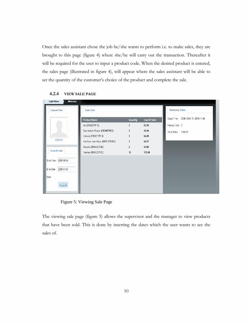
Once the sales assistant chose the job he/she wants to perform i.e. to make sales, they are
brought to this page (figure 4) where she/he will carry out the transaction. Thereafter it
will be required for the user to input a product code. When the desired product is entered,
the sales page (illustrated in figure 4), will appear where the sales assistant will be able to
set the quantity of the customer’s choice of the product and complete the sale.
4.2.4 VIEW SALE PAGE
Figure 5: Viewing Sale Page
The viewing sale page (figure 5) allows the supervisor and the manager to view products
that have been sold. This is done by inserting the dates which the user wants to see the
sales of.

11
4.2.6 STOCK PAGE
Figure 6: Stock Page
The stock page enables the supervisor to add and view the stock that is available. The page
consists of five forms which are: the product name (for the supervisor to add the product
name); the product code; the Quantity (where the supervisor will place the quantity of the
specific product his adding); the Price (which it is inactive because the supervisor does not
have the privileges to set prices) and the Description (where the user has to describe the
product). When the manager logs in, the price form is activated (see figure 7) for him to
set the prices. This is done by the user clicking the edit button of the product he wishes to
set a price to. Once he has done that, the product is reprinted on those forms and then the
manager sets the price.
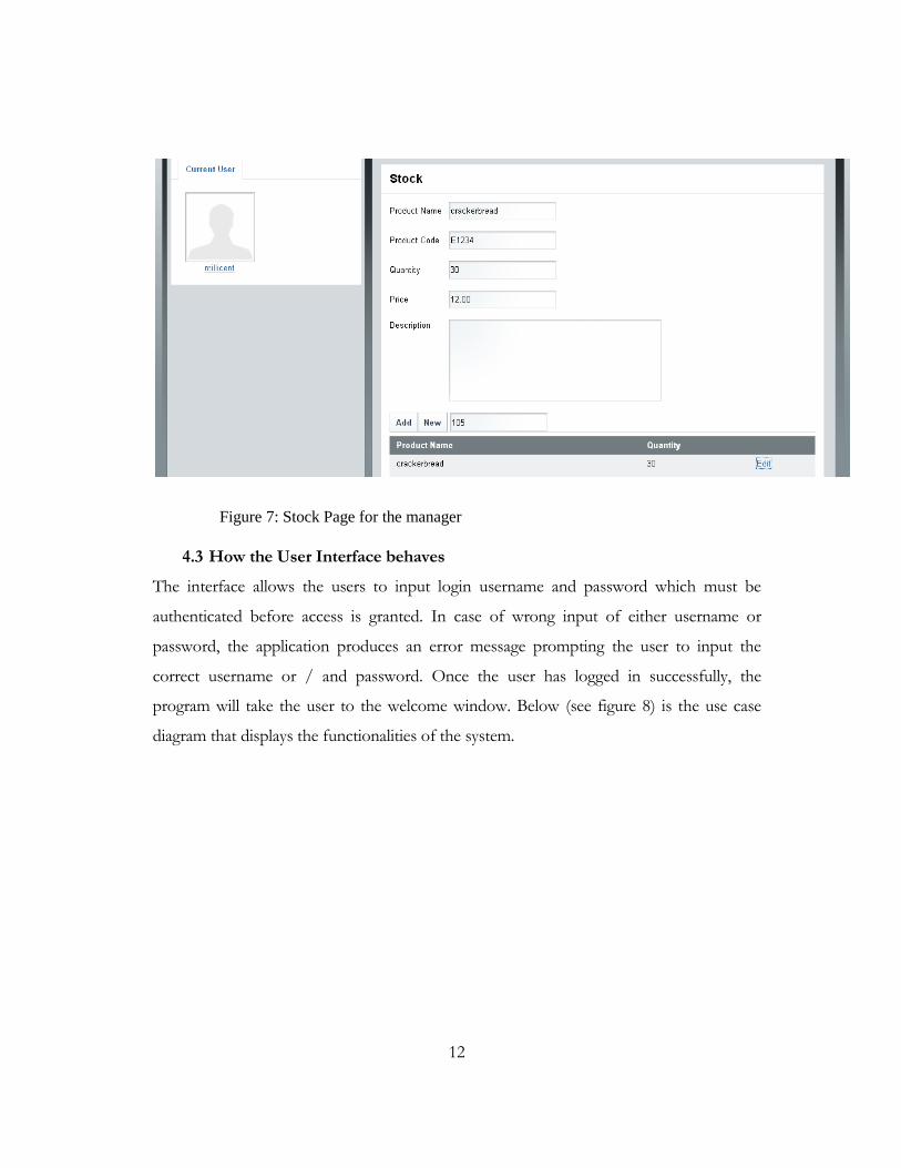
12
Figure 7: Stock Page for the manager
4.3 How the User Interface behaves
The interface allows the users to input login username and password which must be
authenticated before access is granted. In case of wrong input of either username or
password, the application produces an error message prompting the user to input the
correct username or / and password. Once the user has logged in successfully, the
program will take the user to the welcome window. Below (see figure 8) is the use case
diagram that displays the functionalities of the system.

13
Figure 8: Use case diagram
The figure above shows the three actor-databases that the system will have. The user in
the sell of stock database will have the ability to sell products, while the user in the site
office will be able to request sales from the sell of stock database, make a query of stock
items that are remaining and make updates the stock. The user at the head office will have
the ability to sets prices to the stock items that have been added in the site office database,
request sales and query stock.

14
4.4 How the user interacts with the system
4.4.1 HOW THE STUDENT INTERACTS WITH THE SYSTEM
The way the user in the sell of stock database i.e. in the selling terminal will interact with
the system is illustrated below.
Figure 9: Sales assistant activity diagram

15
The following activities are explained by Figure 9:
1. The sales assistant will login to the POS system by entering their name as a
username and a password on the login screen.
2. The system authenticates the sales assistant.
3. The system will display the privileges which the user has.
4. The user select the action he/she wants to perform
5. Thereafter the user chooses the product that the customer wants
6. The system displays the product description of the customer’s choice of product.
7. The user inserts the quantity of the product which the user wants.
8. The system displays the total amount of the product required by the user.
9. The user submits the query to complete the sale.
10. The user logs out

16
4.4.2 HOW THE USER IN THE SITE OFFICE INTERACTS WITH THE SYSTEM
How the user in the site office interacts with the system is summarized in the following
Site Office Activity Diagram.
Figure 10: Site Office Activity diagram
1. The user logs in
2. The system authenticates the user

17
3. The system displays the privileges which the user have.
4. The user select the action he/she wants to perform
5. The user request sales
6. The system retrieves the sale from the sell of stock database.
7. The system displays the sales information
8. The user adds stock
9. The system updates the site office database
10. The system displays the available stock
11. The system synchronizes the data
12. The user logs off.

18
4.4.3 HOW THE USER IN THE HEAD OFFICE INTERACTS WITH THE SYSTEM
4.4.4 How the user in the site office interacts with the system is summarized in the
following Head Office Activity Diagram.
Figure 11: Site Office activity diagram

19
1. The user login
2. The system authenticates the user
3. The system will display the privileges which the user have.
4. The user select the action he/she wants to perform
5. The user request sales
6. The system retrieves the sale from the sell of stock database.
7. The system displays the sales information
8. The user add stock
9. The system updates the site office database
10. The system displays the available stock
11. The system synchronizes the data
12. The user logs off.
4.5 Summary
This chapter described the user interface. The login page, main page and other pages’
functionalities were illustrated. The activity diagrams showed how the different types of
users in various databases (SellOf Stock, SiteOffice and HeadOffice) interact with the
system. Furthermore, the use cases showed what the users will do with the system. The
next chapter will discuss the objects needed to implement the system.

20
C h a p t e r 5
OBJECT ORIENTED ANALYSIS (OOA) OR HIGH LEVEL DESIGN
5.1 Introduction
In the previous chapter we covered the user interface specification and how the user will
interact with the system. In this chapter we will be looking at object oriented analysis
which will describe the object-oriented view of the problem, where every object will be
described and documented in the data dictionary. The relationship between the objects is
shown while the class diagrams display the attributes and method of each class.
5.2 Data Dictionary
The dictionary contains information describing the content of the Data Distributed
System of the POS system.
5.2.1 SELLING TERMINAL IN THE SELL OF STOCK DATABASE OBJECTS
The selling terminal object contains product sales information.

21
Name Description Data type Example
Username The user’s name 20 Characters Keagan
Password Password given by the company 10 Characters User101
Till ID The till that is used to make the
sales since there will be more
than one selling terminal
5 Integer
Number
1245
ItemID Identifier of the product 10 Integer 1002495
Item Name Name of the product 20 character MacBook
Item Quantity Quantity of the item the
customer wants
6 numbers 134
Item Price Price of each item in stock 10 numbers 1500.00
Subtotal The total amount of the items
the customer bought
10 numbers 3000.00
Date Date at which the sale was made Date Time 2009-06-02 02:01:18
Table 1: Selling terminal object
5.2.2 SITE OFFICE OBJECT
The site office object contains the following information.
Name Description Data type Example
Purchased Date The date at which the item
was sold
Date Time 2009-06-02 02:01:18
Table 2: Site office object
5.2.3 HEAD OFFICE OBJECT
The head office object contains following information.
Name Description Data type Example
Selling Price The price at which the
item will be sold by
7 numbers 1500.00
Stock Price The price at which the
stock was bought with.
7 numbers 1000.00
Table 3: Head office object

22
5.3 Class Diagram
The class diagram (figure 12) below shows the relationship between classes in the system.
The main classes are the Sellofstock, Siteoffice and Headoffice. The diagram below shows
that the site office connects to the sellofstock database to get info about the sales made,
while the head office connects to the site office in order to set the prices for the stock
which were added at the site office.
Figure 12: Class diagram
23
5.4 Conclusion
In this chapter, each class and its attributes were explained in detail using the data
dictionary. The data dictionary described the attributes and the data type. Also an example
was given to each attribute. Furthermore, the class diagram demonstrated the relationship
between classes in the system.

24
C h a p t e r 6
OBJECT ORIENTED DESIGN (OOD) OR LOWER LEVEL DESIGN
6.1 Introduction
In the previous chapter, each object was described and documented in the data dictionary.
However, in this chapter, the Object Oriented Design (OOD) will take the classes of the
OOA to a deeper level where a pseudo-code will be written to represent each class. The
OOD defines the data types for the attributes, the algorithms and implementation details
of classes. Also the state and sequence diagrams of the system are explained.
6.2 Inner Details of Class Attributes and Methods
The class diagram described in chapter 5 shows all classes that will be used within the
system. Further, class attributes (data types) were defined in the data dictionary and
methods (functions) are described within the class diagram.
6.3 State Diagram
The state diagram below (figure 13) depicts the dynamic behaviour of the login and
application functions of the system. When the user enters the username and password, the
system validates the entries. If the user is the sales assistant then he/she performs the sale.
At the end of the sale he/she completes the sale by processing payment from the
customer. Thereafter if the sale is not completed, (he/she) continues with the sale(s) until
the end of his/her session. When the user is done with the sales transaction, he/she
synchronises the information to the site office where the site office will trasnfer the
information to the head office. Following that the user can log off to end the session. If
the user logged in as the supervisor from the site office, then he/she can request sales
from the sellofstock to view. Thereafter he/she can logoff or he/she can add stock items
to the database, synchronise the data, and then log off. Alternatively, if the user logged in
as the managers from the head office, he/she can set the prices of the stock that the user

25
in the site office added, or make changes to the existing prices. The information will then
be synchronised to various databases. The user can then log off.
Figure 13: State diagram
26
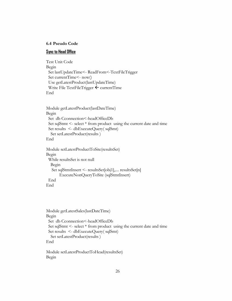
6.4 Pseudo Code
Sync to Head Office Test Unit Code Begin Set lastUpdateTime<- ReadFrom<-TextFileTrigger Set currentTime<- now() Use getLatestProduct(lastUpdateTime)
Write File TextFileTrigger currentTime End Module getLatestProduct(lastDateTime) Begin Set db Cconnection<-headOfficeDb Set sqlStmt <- select * from product using the current date and time Set results <- dbExecuteQuery( sqlSmt) Set setLatestProduct(results ) End Module setLatestProductToSite(resultsSet) Begin While resultsSet is not null Begin Set sqlStmtInsert <- resultsSet[obj1],.... resultsSet[n] ExecuteNonQueryToSite (sqlStmtInsert) End End Module getLatestSales(lastDateTime) Begin Set db Cconnection<-headOfficeDb Set sqlStmt <- select * from product using the current date and time Set results <- dbExecuteQuery( sqlSmt) Set setLatestProduct(results ) End Module setLatestProductToHead(resultsSet) Begin

27
While resultsSet is not null Begin Set sqlStmtInsert <- resultsSet[obj1],.... resultsSet[n] ExecuteNonQueryToHead (sqlStmtInsert) End End
Sync to Site Test Unit Code Begin Set lastUpdateTime<- ReadFrom<-TextFileTrigger Set currentTime<- now() Use getLatestProduct(lastUpdateTime)
Write File TextFileTrigger currentTime End Module getLatestProduct(lastDateTime) Begin Set db Cconnection<-SiteDb Set sqlStmt <- select * from product using the current date and time Set results <- dbExecuteQuery( sqlSmt) Set setLatestProduct(results ) End Module setLatestProductToSite(resultsSet) Begin While resultsSet is not null Begin Set sqlStmtInsert <- resultsSet[obj1],.... resultsSet[n] ExecuteNonQueryToSite (sqlStmtInsert) End End Module getLatestSales(lastDateTime) Begin Set db Cconnection<-SiteDb Set sqlStmt <- select * from sales using the current date and time Set results <- dbExecuteQuery( sqlSmt) Set setLatestSalesToSite (results )

28
End Module setLatestSalesToSite(resultsSet) Begin While resultsSet is not null Begin Set sqlStmtInsert <- resultsSet[obj1],.... resultsSet[n] ExecuteNonQueryToSite (sqlStmtInsert) End End
6.3 Conclusion
In this chapter we outlined various diagrams that form part of the OOD, written in a form
which is understandable and which will be easy to convert into a programming language.
The state diagram was also covered in the chapter. Pseudo code was also provided to
indicate the implementation of the code.

29
C h a p t e r 7
SYSTEM TESTING
8.1 Introduction
In the previous chapter we explained the user manual that describes a basic way in which
the user would interact with the system. In this chapter, we document the process of
testing both the user interface and the system, to ensure robustness and adherence to the
stipulated requirements.
8.2 Testing the user interface
PLANNING THE TEST
The Computer Science honours lab and Chris Hani Residence were used for the testing of
the system. Four participants were asked to assist in the carrying out the testing phase. A
brief description of the participants is listed below.
PARTICIPANTS GENDER ENVIROMENT COMPUTER LITERATE
YEAR OF STUDYING
1 Male Computer Science lab
Yes 2nd year
2 Female Computer Science lab
Yes 3rd year
3 Male Chris Hani Yes 3rd year
4 Female Chris Hani Yes 3rd year
Table 4: Participants Details

30
PROCEDURE
A Computer was set up for the testing
The Participants were given a consent form to complete
A user manual was provided for the participants to use
A Questionnaire was given to the participants to complete to gather feedback
information
8.3 Test result and Discussion
FUNCTIONALITY TESTING
Functionality testing involved testing of the interface pages, links, buttons and the
database. During this test, users tested the core functions of the system, including the
synchronization of data. By making transactions, viewing sales (to check if the data was
updated to other databases), and adding stock and prices.
a. Links
Links were tested and they all worked perfectly. Users used the links and accessed
the expected pages.
b. Database
Database testing was successful as all users managed to update and retrieve
information effectively. There was no missing or incorrect data in tables nor were
there errors in writing, editing or locating information from tables.

31
c. Core Function
Synchronisation process
This process was performed by carrying out some actions. Below are some of the
participant’s feedback on different the tasks that they engaged in.
Participant 1
Making the sales- The participant felt that the system was easy to use and
the user manual made it even more efficient. Also, that the
synchronisation of the sales made was done successfully for it managed to
synchronise every minute.
Adding stock- The participant was satisfied with this process and the
synchronisation to different databases was successful.
Adding prices – The participant felt that the interface and the command
button was a good idea but then other functions need to be looked at
since the edit button did not retrieve the product information from the
database.
Participant 2
Making sales- The participant felt the system to be simple and self
explanatory and was satisfied with it even the synchronisation process.
Adding stock- The participant was happy with the synchronisation of the
new product added in the database.
Adding prices- The participant felt that the edit function should be looked
at because the information could not be retrieved.

32
Participant 3
Making sales- The participant had a great experience using the system. He
followed each step and had no problem in making a sales transaction.
Adding stock – The participant was satisfied with adding stock and the
synchronisation process.
Adding prices- The participant was disappointed in the adding of the
prices since other functions did not work properly and suggested that the
function should be fixed.
Participant 4
Making sales- The participant was excited in using the system and was
satisfied with how the synchronisation to different databases was carried
out.
Adding stock – The participant was happy with this process and had no
problem in completing the task.
Adding prices – The participant felt that the system was consistent
however; she felt that there is a halt in the system because other functions
needed to be attended to.
Areas of improvement:
All four participants suggested that the edit function when adding a price should be looked
at so that it can be able to retrieve information of that product. This change is shown
below (see figure 14). The edit function is now active which means that when the user
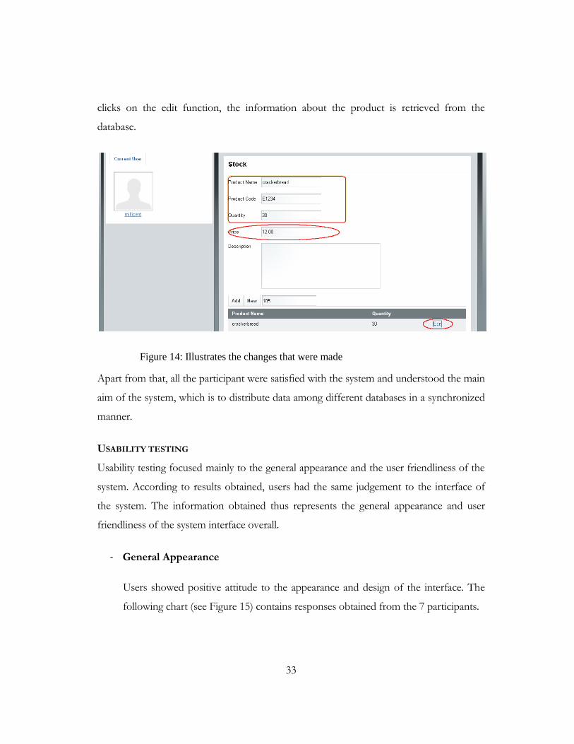
33
clicks on the edit function, the information about the product is retrieved from the
database.
Figure 14: Illustrates the changes that were made
Apart from that, all the participant were satisfied with the system and understood the main
aim of the system, which is to distribute data among different databases in a synchronized
manner.
USABILITY TESTING
Usability testing focused mainly to the general appearance and the user friendliness of the
system. According to results obtained, users had the same judgement to the interface of
the system. The information obtained thus represents the general appearance and user
friendliness of the system interface overall.
- General Appearance
Users showed positive attitude to the appearance and design of the interface. The
following chart (see Figure 15) contains responses obtained from the 7 participants.

34
Figure 15: Illustrates the interface quality of the system
- Performance testing:
All users reported that the system was easy to understand and use and that the
system was not slow. They felt that the system was efficient and would be more so
if all the functions would be in working order. The following bar-graph (see Figure
16) represents the users’ responses to the system’s performance.
0
1
2
3
4
5
6
Very Good Good Moderate Bad Very Bad
Par
tici
pan
tsInterface Quality

35
Figure 16: Illustrates the performance of the system
8.2 Compatibility testing
This test was conducted to evaluate the application's compatibility with the computing
environment: personal computer (PC), laptop and virtual machine as well as web
browsers.
The following devices were used successfully:
- Computing capacity of PC
o Dell Laptop : this was used by two users from Chris Hani residence
o Sun Microsystems: was used by two users
- PC Browser compatibility (Firefox, Internet Explorer, Safari)
During browser compatibility testing the application was tested against different
web browsers to ensure that it works appropriately. Using PC’s users tested the
application with Firefox 3.5.1 and the interface was admired as all objects were in
place and worked as expected.
0
1
2
3
4
5
6
Good Acceptable Slow
par
tici
pan
ts
System's Performance

36
For Internet Explorer 6, the interface was fine for all the users. However, other
images were not visible and it was a bit slow. While for Safari 4.0.3 the browser
was fast but other images were not visible.

37
C h a p t e r 8
USER GUIDE
8.1 Introduction
The previous chapter talked about system testing, focusing on strategies used, the test
results and their discussion. This chapter provides a detailed system user guide helping the
users to understand how the system works. Below we cover a chronological step by step
process in order to successfully use the system. The following list is all the tasks the user
should complete:
1. Making Sales
2. Checking the sales for the sales assistants
3. Adding stock
4. Adding prices to a new stock
8.1.1 Making Sales
To make a sale transaction, first login to the system using the sales assistant’s login details.
Figure 17 displays the login screen. After entering the details click on the login button.

38
Figure 17: Illustrates the login page of the system
Once you have successfully logged in, you should go to the navigation drop down box
where you will choose which action to perform, which is to make sales in this case.
Therefore choose the sell stock option.
Figure 18: Welcome page with a navigation button

39
From there a new window will appear which will require the insertion of the code of the
product to perform the transaction. Once done insert the quantity of the product the user
wishes to purchase and the amount the user will be paying. Once the purchase is done,
click on save to update the database of the transaction that was performed and for the
synchronisation to take place.
Figure 19: Sales page
8.1.2 Checking the sales for the sales assistants
From the navigation button, choose the view sale option where you will be required to
insert the date of the sales you wish to view. Thereafter click on the search button for the
information to be retrieved from the database.

40
Figure 20: Viewing sales page
8.1.3 Adding stock
Login with the supervisor’s password and username .Following the login, go to the
navigation button where you should choose adding stock option. Once complete, the
stock form will appear where you will be required to enter details of the product you wish
to have in stock. Then click on the add button to save the information to the database.

41
Figure 21: Stock adding page
8.1.4 Adding price to a new stock
Login with the manager’s login details. From there go to the navigation button where you
should choose the add price option. Once that is complete, the stock form will appear
along with the stock products that are in the database. Alongside every product there is an
edit option where you should click to edit that specific product. Information about that
product will appear in the stock form where you would be required to input the price for
that product. Once that is complete, click on the add button to save the changes you have
made.

42
Figure 22: Price adding page
8.2 Conclusion
This chapter provided a user manual containing step by step instructions of how to
perform various tasks on the system. The system’s screen shots were used to support the
documentation.
43
Chapter 9
PROBLEMS ENCOUNTERED DURING PROJECT DEVELOPMENT
9.1 Introduction
In the previous chapter we took a look at the various testing methods that where
implemented, in this project. In this chapter we take look at the various difficulties that
where encountered during the development of the project. The problems defined here
were not able to be resolved before the final product was handed in for evaluation.
9.2 During Synchronisation Process
Our initial idea was to have the sync process a web driven event, thus having a page with a
button to invoke the synchronisation for each category. The solution had its draw back.
The best idea was to have an NT service or Window service to do that. Hence we could
not proceed with it since had to be done using .Net Framework. We had to stick to a
solution that works which was ncron or crontab that can work in Linux and Windows for
scheduling.
Another problem was that every time the sync occurred, all the rows to be synchronised
were retrieved which was unnecessary, hence we decided to use some form of trigger in
our update, which keeps the information from the last update. With the trigger
implemented, Every time we updated the system checks when the last update was, and
continues from there.
9.3 During Analysis and Development
The idea was to use something different and new in the web development, and we decided
to go with php5XXX and Jquery for user interactions. The hard part was the

44
understanding of Jquery and all its details. Eventually we got hold of it and it we managed
to do what we had planned.
Another difficulty involved a change of the requirements from the supervisor which made
me to change the code from the user interface and classes.
9.4 Conclusion
In this chapter we discussed the various problems that occurred when developing the
software. This was done to help a future developer to find out how to solve the problems
here before attempting the development of the system only to encounter the same
problems.

45
BIBLIOGRAPHY
- Kevin Tatroe & Lerdorf. (n.d.). Creating Dyamic Web Pages, Programming PHP,
O'REILLY. Retrieved 2009, from www.books.google.co.za:
http://books.google.co.za/books?id=7OjvOmol3CcC&dq=php&printsec=frontc
over&source=bl&ots=1oRkbZ44z.
- Mehdi Achour, Friedhelm Betz and Antony Dovgal. (2009, 7 24). PHP Manual. (P.
Olson, Ed.) Retrieved 7 27, 2009, from www.php.net:
http://www.php.net/manual/en/intro-whatis.php.
- Peter Rob and C. Coronel. (2007). Database System, Design, Implementation and
Management (7th ed.).
- phpmyadmin. (2009). Retrieved 7 28, 2009, from www.phpmyadmin.net:
http://www.phpmyadmin.net/home_page/index.php.
- Ralph Stair, George Reynolds & Thomas Chesney. (2008). Fundamentals of Business
Information Systems. London: Cengage Learning EMEA.
- Sun Microsystems, Inc. (2009). MySQL. Retrieved 7 28, 2009, from
www.dev.mysql.com: http://dev.mysql.com/doc/refman/5.0/en/what-is-
mysql.html.
- Dummies. (2004). PHP & MySQL 2nd Edition.
- Jquery. (2009, 7 22). Retrieved 7 28, 2009, from http://jquery.com/.
- Michael Mahemoff. Ajax Design Patterns, Creating Web 2.0 Sites with
Programming and Usability Patterns, O'REILLY. Retrieved 2009, from
http://books.google.co.za/books?id=i8UH8NBp7qoC&dq=Ajax&printsec=fro
ntcover&source=bl&ots=6tp7m9-
Wwp&sig=mDoiK21gAL4IuRCeNvCeVOD6pVY&hl=en&ei=5Av0SpKKPM
Wj4QanpYDcAw&sa=X&oi=book_result&ct=result&resnum=11&ved=0CDY
Q6AEwCg#v=onepage&q=&f=false.

46
APPENDICES
APPENDIX A
System Testing Questionnaire
My name is Pulane Millicent Molebale, I am a student at UWC doing Computer Sciences. I am currently carrying out an academic project titled“Data Distribution System” which intends to solve problems on how the distribution of data is currently implemented. I wish to collect information from you through this questionnaire. Please be advised that the information that you give to me is confidential. Please fill this questionnaire in the spaces provided.
Task 1: Making sales Steps
1. Login to the system using as the sales assistant 2. Choose the action you want to perform (sell stock) 3. Input the product code of the product you wish to purchase 4. Choose the quantity of the product 5. The amount of which you are paying 6. Click on save to save the above transaction 7. Have a look on the different databases if the info has been updated and synchronised 8. Logout
Task 1. 2: Checking the sales for the sales assistants Steps
1. Input the date of the sales you want to see 2. Click search 3. Logout
Questions
1. Respondent details
Gender : _________________________
Year of study: _________________________
Computer Literate
2. Have you encountered any problems during this process? If yes please explain
Yes No

47
_______________________________________________________________
_______________________________________________________________
_______________________________________________________________
3. How easy was the process?
Very easy Easy Moderately easy Difficult Very difficult
Please motivate your answer
______________________________________________________________
4. Was the performance of the system in terms of response time?
Good Acceptable Too slow
5. Were the various databases updated?
6. Was the synchronisation done to your satisfaction?
Please motivate your answer
_______________________________________________________________
_______________________________________________________________
7. What modification would you suggest?
_______________________________________________________________
_______________________________________________________________
_______________________________________________________________
Task 2: adding stock Steps:
1. Login to the system as the supervisor
2. Choose the action you want to perform (add stock)
3. Fill in the form
4. Click the add button when you’re done with the form
5. Have a look on the different databases if the info has been updated and
synchronised
6. Logout
Questions
Yes No
Yes No

48
1. Have you encountered any problems during this process? If yes please explain
_______________________________________________________________
_______________________________________________________________
_______________________________________________________________
2. How easy was the process?
Very easy Easy Moderately easy Difficult Very difficult
Please motivate your answer
______________________________________________________________
3. Was the performance of the system in terms of response time?
Good Acceptable Too slow
4. Were the various databases updated?
5. Was the synchronisation done to your satisfaction?
Please motivate your answer
_______________________________________________________________
_______________________________________________________________
6. What modification would you suggest?
_______________________________________________________________
_______________________________________________________________
_______________________________________________________________
Task 3: Adding price to a new stock Steps:
1. Login to the system as the manager
2. Choose the action you want to perform(add price)
3. Click on the edit function for the product you wish to add price to
4. Add the price for that specified product
5. Click the add button when the edition is done
6. Have a look on the different databases if the info has been updated and
synchronised
Yes No
Yes No

49
7. Logout
Questions
1. Have you encountered any problems during this process? If yes please explain
_______________________________________________________________
_______________________________________________________________
_______________________________________________________________
2. How easy was the process?
Very easy Easy Moderately easy Difficult Very difficult
Please motivate your answer
______________________________________________________________
3. Was the performance of the system in terms of response time?
Good Acceptable Too slow
4. Were the various databases updated?
5. Was the synchronisation done to your satisfaction?
Please motivate your answer
_______________________________________________________________
_______________________________________________________________
6. What modification would you suggest?
_______________________________________________________________
_______________________________________________________________
_______________________________________________________________
Yes No
Yes No

50
APPENDIX B
CODE DOCUMENTATION
SUMMARY
In the previous chapter we focused on the testing phase of the project. In this chapter the
code documentation will not be discussed due to the large files; however, it has been
attached as Appendix C. This has been done by storing the source code on a CD and
placing it an envelope.

51