department of mechanical engineering lab manual
TRANSCRIPT
Prof.B.Murali www.vidyarthiplus.com Prof.P.Amirthalingam
www.veltechengg.com
DEPARTMENT OF MECHANICAL ENGINEERING
LAB MANUAL
2017 Regulations
Subject Code : GE 8261
Subject Name : ENGINEERING PRACTICES
Year/Semester : I/II
Prepared By:
1. Prof.B.Murali. BE (Mech)., ME (Engg Design)
Assistant Professor
Department of Mechanical Engineering
Vel Tech (Owned By RS Trust)
Avadi, Chennai-62
2. Prof.P.Amirthalingam.BE (Mech)., ME (Manufacturing Engg)
Assistant Professor
Department of Mechanical Engineering
Vel Tech (Owned By RS Trust)
Avadi, Chennai-62

Prof.B.Murali www.vidyarthiplus.com Prof.P.Amirthalingam
www.veltechengg.com
GE8261 ENGINEERING PRACTICES LABORATORY
OBJECTIVES:
To provide exposure to the students with hands on experience on various basic engineering
practices in Civil, Mechanical, Engineering.
GROUP A (CIVIL & MECHANICAL)
I-CIVIL ENGINEERING PRACTICE
Buildings:
(a) Study of plumbing and carpentry components of residential and industrial buildings. Safety
aspects.
Plumbing Works:
(a) Study of pipeline joints, its location and functions: valves, taps, couplings, unions, reducers,
elbows in household fittings.
(b) Study of pipe connections requirements for pumps and turbines.
(c) Preparation of plumbing line sketches for water supply and sewage works.
(d) Hands-on-exercise: Basic pipe connections – Mixed pipe material connection – Pipe
connections with different joining components.
(e) Demonstration of plumbing requirements of high-rise buildings
Carpentry using Power Tools only:
(a) Study of the joints in roofs, doors, windows and furniture.
(b) Hands-on-exercise: Wood work, joints by sawing, planning and cutting.
II-MECHANICAL ENGINEERING PRACTICE
Welding:
(a) Preparation of butt joints, lap joints and T- joints by Shielded metal arc welding.
(b) Gas welding practice
Basic Machining:
(a) Simple Turning and Taper turning
(b) Drilling Practice
Sheet Metal Work:
(a) Forming & Bending:
(b) Model making – Trays and funnels.
(c) Different type of joints.
Prof.B.Murali www.vidyarthiplus.com Prof.P.Amirthalingam
www.veltechengg.com
Machine assembly practice:
(a) Study of centrifugal pump
(b) Study of air conditioner
Demonstration on:
(a) Smithy operations, upsetting, swaging, setting down and bending. Example – Exercise –
Production of hexagonal headed bolt.
(b) Foundry operations like mould preparation for gear and step cone pulley.
(c) Fitting – Exercises – Preparation of square fitting and V – fitting models.
OUTCOMES:
On successful completion of this course, the student will be able to
Fabricate carpentry components and pipe connections including plumbing works.
Use welding equipments to join the structures.
Carry out the basic machining operations
Make the models using sheet metal works
Illustrate on centrifugal pump, Air conditioner, operations of smithy, foundry and
fittings

Prof.B.Murali www.vidyarthiplus.com Prof.P.Amirthalingam
www.veltechengg.com
GE8261 – ENGINEERING PRACTICES LAB (CIVIL & MECHANICAL)
CONTENTS
Ex. No. TITLE OF EXPERIMENT Page No.
WELDING
Introduction 1
1 SINGLE V-BUTT JOINT 7
2 LAP JOINT 9
3 T-FILLET JOINT 11
PLUMBING
Introduction 12
4 CONNECTION OF TWO GALVANISED IRON PIPES 19
5 CONNECTION OF PVC PIPES 21
6 BASIC PIPE CONNECTIONS INVOLVING THE FITTING LIKE
23
VALVES, TAPS AND BENDS
SHEET METAL
Introduction 25
7 RECTANGULAR TRAY 31
8 FUNNEL 33
CARPENTRY
Introduction 35
9 CROSS LAP JOINT 41
10 MORTISE AND TENON JOINT 43
BASIC MACHINING
Introduction 45
11 FACING, TURNING, STEP TURNING, CHAMFERING AND TAPER
53
TURNING
12 DRILLING AND TAPPING 55
STUDY EXERCISES
1 STUDY OF CENTRIFUGAL PUMP 59
2 STUDY OF AIR CONDITIONER 61
DEMONSTRATION EXERCISES
SMITHY
Introduction 65
1 MAKING A ROUND ROD INTO HEXAGONAL HEADED BOLT 67
FOUNDRY
Introduction 71
2 GEAR 73
3 STEPPED CONE PULLEY 75
FITTING
Introduction 79
4 SQUARE FITTING 81
5 VEE FITTING 83

Prof.B.Murali www.vidyarthiplus.com Prof.P.Amirthalingam
www.veltechengg.com
WELDING

Prof.B.Murali www.vidyarthiplus.com Prof.P.Amirthalingam
www.veltechengg.com
.
Welding
Plastic Welding (non- Fusion Welding (no
Fusion)(Under pressure, pressure is required, but
Without addition of with the addition of
filler material filler material
Forge Resistance Gas Electric arc Thermit
Welding
Welding Welding Welding welding
(a) Lap Welding (a) Spot (a) Oxy- (a) Metal Arc Welding
(b) Butt Welding Welding Acetylene (b) Arc Welding
(c) V – Welding (b) Projection Welding (c) Tungsten Welding
(d) T - Welding Welding (b) Air- (d) Argon Welding
(c) Seam Acetylene (e) Submerged Arc
Welding Welding Welding
(d) Butt (c) Oxy- (f) Atomic Hydrogen
Welding hydrogen Welding
(e) Percussion
Welding
Welding

Prof.B.Murali www.vidyarthiplus.com Prof.P.Amirthalingam
www.veltechengg.com
WELDING
Introduction:
Welding is a metal joining process wherein localized coalescence is produced either
by heating the metal to a suitable temperature, with or without the use of filler metal, with or
without application of pressure. The filler material has similar compositional melting point
temperature as that of the base metal. It is used to fill gap between the join surfaces.
Types of welding:
Welding process is mainly divided into the subdivisions as follows:
1. Plastic welding: The pieces of the metal to be joined are heated to the plastic state and
then forced together by external pressure without the addition of filler material.
Plastic welding is further classified as:
(a) Forge welding (b) Resistance welding
2. Fusion welding:
In fusion welding, metal parts to be joined are melted and then allowed to
solidify pressure is not applied and filler metals may be used for this type of welding.
Fusion welding is further classified as:
(a) Gas welding (b) Electric arc welding (c) Thermit welding
3. Oxy-Acetylene welding:
Here, oxygen and acetylene are the two gases are used for producing flame.
Oxygen is mainly used for supporting the combustion intensity. A typical oxy-acetylene gas welding setup is used.
Chemical reactions in gas welding:
C2H2 + O2 → 2CO + H2 + Heat
2CO + O2 → 2CO2
2H2 + O2 → 2H2O
Types of flames:
1.Neutral flame ( oxygen, acetylene in equal proportions )
2. Oxidizing flame ( excess of oxygen )
3. Reducing flame (excess of acetylene ) Limitations:
In this method, only those metals whose combustion temperature is below their melting point can be cut. So iron and steel can be cut flame cutting.
Principle:
The heat required for joining the metal is obtained from an electric arc. The electric
motor generator or transformer sets are used to supply high electric current and the
electrodes are used to produce the necessary are. The electrode saves as the filler rod and
are melts the surfaces so that the metals to be joined are fused together.

Prof.B.Murali www.vidyarthiplus.com Prof.P.Amirthalingam
www.veltechengg.com
.
Prof.B.Murali www.vidyarthiplus.com Prof.P.Amirthalingam
www.veltechengg.com
Welding bed cleaning accessories:
1. Wire bush:
A wire bush made up of stiff steel wire.
2. Chipping hammer:
A chipping hammer is chisel shaped one and it is used to remove the slag from the weld bed.
3. Hand screen:
It is a protective device used in arc welding. A hand shield is held in the hand of the welder and it is fitted with a suitable fitter lens.
4. Helmet:
It is used for shielding and protecting the face and neck of the welder and it is fitted with
a suitable fitter lens.
5. Tongs:
Tongs are used to handle the hot metal welding job while cleaning they are also used to hold the metal for hammering.
6. Goggles:
Chipple joggle are used to protect the eyes while chipping the slay. They are fitted with
a plain glass to see the area to be cleaned.
7. Hand gloves:
Hand gloves are used to protect the hands from electric shocks, arc radiation and hot spatters.

Prof.B.Murali www.vidyarthiplus.com Prof.P.Amirthalingam
www.veltechengg.com
.

Prof.B.Murali www.vidyarthiplus.com Prof.P.Amirthalingam
www.veltechengg.com
.
Ex.No.1 SINGLE V-BUTT JOINT
AIM:
To make a Single V-Butt joint using arc welding on the given work pieces.
Material supplied:
Mild steel plate of size 100 x 50 x 6mm - 2 Nos.
Tools required:
1. Power supply (AC or DC)
2. Welding Torch 3. Electrodes
4. Tongs 5. Chipping hammer
6. Wire brush 7. Gloves
8. Apron 9. Shield
10. Safety goggles 11. Earthing clamps
Sequence of operations:
1. Edge preparation (Removal of rust, scale etc.,)
2. Tacking 3. Welding
4. Cooling 5. Chipping
6. Cleaning
Working steps: 1. First of all, the work pieces must be thoroughly cleaned to remove rust, scale and other foreign
materials. 2. Then the given work pieces are placed on the table in such a way that two work pieces are
brought close to each other so that it forms a ‘V-Shape’ when the plates butt each other. 3. Appropriate power supply should be given to the electrode and work pieces. 4. Now the welding current output may be existed. 5. When current is passed, arc is produced between the electrode and work pieces.
6. Now set the two work pieces in correct position and maintain the gap 3mm and drack at both
ends of the work pieces as shown in the figure. 7. Then the welding is carried out throughout the length. 8. As soon as the welding process is finished, switched off the current supply and allow the work
piece to cool. 9. Slags are removed by chipping process with the help of chipping hammer. 10. Finally using wire brush, welded portions are cleaned.
Result:
Thus the desired Single V-Butt joint is obtained using arc welding.
7

Prof.B.Murali www.vidyarthiplus.com Prof.P.Amirthalingam
www.veltechengg.com
.

Prof.B.Murali www.vidyarthiplus.com Prof.P.Amirthalingam
www.veltechengg.com
LAP JOINT
Ex.No.2
Aim:
To make a lap joint using arc welding on the given workpieces.
Material supplied: Mild steel plate of size 102 x 51 x 6mm - 2 Nos.
Tools required:
1. Power supply (AC or DC)
2. Welding Torch 3. Electrodes
4. Tongs 5. Chipping hammer
6. Wire brush 7. Gloves
8. Apron 9. Shield
10. Safety goggles 11. Earthing clamps
Sequence of operations:
1. Edge preparation (Removal of rust, scale etc.,)
2. Tacking 3. Welding
4. Cooling 5. Chipping
6. Cleaning
Working steps:
1. First of all, the work pieces must be thoroughly cleaned to remove rust, scale and other
foreign materials.
2. Then the given work pieces are placed on the table in such a way that two work pieces
are overlapped one over another as shown in fig. 3. Appropriate power supply should be given to the electrode and work pieces. 4. Now the welding current output may be existed. 5. When current is passed, arc is produced between the electrode and work pieces. 6. Set the two work pieces in correct position like lap joint and tack at both ends of the
work pieces as shown in the figure. 7. Then the welding is carried out throughout the length of the work piece. 8. As soon as the welding process is finished, switch off the current supply and allow the
work piece to cool. 9. Slags are removed by chipping process with the help of chipping hammer. 10. Finally using wire brush, welded portions are cleaned.

Prof.B.Murali www.vidyarthiplus.com Prof.P.Amirthalingam
www.veltechengg.com
Result:
Thus the desired lap joint is obtained using arc welding.
Prof.B.Murali www.vidyarthiplus.com Prof.P.Amirthalingam
www.veltechengg.com
Ex.No.3 T-FILLET JOINT
Aim:
To make a T-Fillet joint using arc welding on the given workpieces.
Material supplied:
Mild steel plate of size 100 x 50 x 6mm - 2 Nos.
Tools required:
1. Power supply (AC or DC) 2. Welding Torch
3. Electrodes 4. Tongs
5. Chipping hammer 6. Wire brush
7. Gloves 8. Apron
9. Shield 10. Safety goggles
11. Earthing clamps
Sequence of operations:
1. Edge preparation (Removal of rust, scale etc.,) 2. Tacking
3. Welding 4. Cooling
5. Chipping 6. Cleaning
Working steps:
1. First of all, the work pieces must be thoroughly cleaned to remove rust, scale and other
foreign materials. 2. Then the given work pieces are placed on the table in such a way that two work pieces
are brought close to each other so that it forms a ‘T’ shape is shown in the fig. 3. Appropriate power supply should be given to the electrode and work pieces. 4. Now the welding current output may be existed. 5. When current is passed, arc is produced between the electrode and work pieces. 6. Set the two work pieces in correct position like T-Fillet joint and tack at both ends of the
work pieces as shown in the figure. 7. The joint is placed on a welding table in a flat position by keeping the tack side down. 8. Then the welding is carried out throughout the length. 9. As soon as the welding process is finished, switched off the current supply and allow the
work piece to cool. 10. Slags are removed by chipping process with the help of chipping hammer. 11. Finally using wire brush, welded portions are cleaned.
Result:
Thus the desired T-Fillet joint is obtained using arc welding.

Prof.B.Murali www.vidyarthiplus.com Prof.P.Amirthalingam
www.veltechengg.com
.
PLUMBING
Prof.B.Murali www.vidyarthiplus.com Prof.P.Amirthalingam
www.veltechengg.com
.

Prof.B.Murali www.vidyarthiplus.com Prof.P.Amirthalingam
www.veltechengg.com
PLUMBING
Introduction: Plumbing is the art of design, installation and maintenance of pipe, pipe fittings and other
accessories in a building. It plays a major role in the construction of every building. Plumbing includes
the pipes, fixtures and accessories which carry water from the main source of supply to the building. It
also conveys the used fluids from a building to other place of local disposal.Water distribution system
consists of a supply pipe leading to a fixture and a drain pipe taking the used water away. Purpose of plumbing:
Plumbing is installed in a building for the comfort and convenience of the inhabitants as well
as sanitation and health. Water is brought by supply pipes and used water is carried off by drainage
pipes. Good plumbing is necessary in houses, apartments, commercial and other public buildings. Tools used by plumber:
The tools used by plumber can be classified as follows.
TOOLS EXAMPLE
1. Guiding & testing tools Straight edge, Level, Plumb bob
2. Marking tools Pencil, Chalk liner, punches, scriber
3. Measuring tools Rule, Tape
4. Holding tools Pliers, Clamps, Wrenches, Vices
5. Cutting tools Saws, Files, Chisels
6. Scraping & Grinding tools Scraper, Grinders
7. Boring & Threading tools Drills, Taps, Pipe vice, Pipe cutter
8. Striking & Fastening tools Hammers, Screwdrivers
Pipe threading dies:
(a) It is also called stocks and dies.
(b) Two types of dies are available viz., solid and adjustable. (c) There are fitted into the centre of the frame. Dies are held in position by a block which is
adjustable by means of a tommy bar. (d) This stock cuts parallel threads.
(e) Separate set of dies are required for each pipe size.
Pipe fittings:
A lot of fittings are used for joining pipes. Cast iron pipes of larger size are joined with
flanges while small size pipes are joined by sockets. Some of the accessories used in pipe fitting are 1. Socket:
Its outside diameter is somewhat larger than the diameter of the pipe.

Prof.B.Murali www.vidyarthiplus.com Prof.P.Amirthalingam
www.veltechengg.com
Its inside diameter is equal to that of pipe’s diameter.
It is used to bring two pipes in a straight direction.
Prof.B.Murali www.vidyarthiplus.com Prof.P.Amirthalingam
www.veltechengg.com
2. Elbow: It is similar to the socket. It is used for fitting two pipes at right angles.Internal threads are
cut in the elbows.
3. Bend:
It is used at corners in pipe fitting jobs. Its diameter is equal to the size of the pipe. Threads are cuts on both its ends and it is joined to the sockets and pipes.
4. T-Joint: It is used for giving connection from the main pipe line to the branch line. By using it, two
or more lines can be made from the supply line.
5. Four way cross: Its shape is like (+) signs. It is used for fitting a pipe in all four directions. Threads are cut
in all its four ends.
6. Valves: Pipes can be joined with valves and according to our needs; we can stop or open the flow of
water through the pipes. Types of valves are: Safety valve, Check valve, Ball valve, Air
release valve, Silence valve, Non-return valve, Globe valve, Gate valve, Wheel valve.
7. Cock:
It serves the purpose of putting off or on the flowing water through the pipes. It is made up of copper, plastics, gun metal. Types of cock are: Bib cock, Stop cock, Push
cock, Plug stop cock, Plug bib cock, Surgeon cock, Pillar cock, Peot cock, Locking cock, Combination cock
8. Pipe union: It connects two pipes. Water meter is fitted with union so that they can be
removed easily. It provides facility to disconnect pipes.
9. Coupling: Short cylindrical sleeve with internal threads throughout its length. It is used for joining two
pipes in a straight line and where atleast one pipe can be turned.
10. Bush: It is a short sleeve like piece, used to reduce the size of a threaded opening. It is threaded
inside fully throughout its length and threaded outside at one outer end. The other outer end is hexagon shape.
11. Plug: Short piece with external threads at one end and square end on the other to receive the
spanner for operation. Used to screw on to a threaded opening, for temporary closing. A cap
may be used for closing external threaded openings temporarily.
12. Flange: It contains internal threads in the hub and holes in the body to receive bolts. Two pipes may
be joined together in line, using flanges and bolts. Flanges are available either in oval or in
circular shapes.
13. Socket reducer:
It is used to connect a big pipe to a small pipe face to face.

Prof.B.Murali www.vidyarthiplus.com Prof.P.Amirthalingam
www.veltechengg.com
.
Prof.B.Murali www.vidyarthiplus.com Prof.P.Amirthalingam
www.veltechengg.com
EX.No.4 CONNECTION OF TWO GALVANISED IRON PIPES
Aim:
To connect the given two galvanized iron pipes by running joint or connector joint.
Materials supplied:
1. Two G.I Pipes 2. Spanner
3. Back nut 4. Socket
5. Pipe wrench.
Procedure:
1. There are two pipes A and B shown in the figure which are to be joined.
2. Pipe wrench is used for holding the pipes. 3. Make external threads to both pipes A and B using pipe threading dies.
4. Some hemp and white lead paint is inserted in the threads to make the joint sound. 5. Pipe B have threads of more length than the pipe A. Back nut (D) is screwed to
the pipe B. It is used for preventing the joint from running loose. 6. The socket C is screwed back to its full length on the pipe B.
7. Both pipes A and B are kept closer. 8. The socket is then screwed back such that it stands half on one pipe A and half on
the other pipe B. 9. A back or locking nut D is used which grips the socket and make it tight. Spanner
is used for tightening the joint.
Result:
Thus the given two G.I. pipes are connected.
.

Prof.B.Murali www.vidyarthiplus.com Prof.P.Amirthalingam
www.veltechengg.com
Ex.No.5 CONNECTIONS OF PVC PIPES
Aim:
To connect the given PVC pipes by running joint and other by T- Joint.
Material supplied:
1. 5 PVC Pipes
2. Couplings
3. Sand paper
4. Solution
Procedure:
Running Joint:
1. There are two PVC pipes A and B shown in the figure which are to be connected.
2. Now with fine sand paper rub the corner end of the pipe, so that we can do a perfect joint. 3. After the rubbing process is completed apply the solution on the two pipes and also on the
coupling. 4. Now with force the pipes are inserted in to the coupling. 5. For two minutes the pipes and coupling are kept undisturbed.
T- Joint:
1. There are 3 pipes D, E and F shown in the figure which are to be connected. 2. Now with fine sand paper corner ends of the pipe are rubbed, so that we can get a perfect
joint.
3. Now the solution is applied is applied on the pipe and also on the Tee.
4. Now with force the pipes are inserted into the Tee one by one. 5. For two minutes the pipes and coupling are kept undisturbed.
Result:
Thus the given PVC pipes are connected using running joint and Tee joint.
Prof.B.Murali www.vidyarthiplus.com Prof.P.Amirthalingam
www.veltechengg.com
.
Pipe Connections Involving The Fitting Like Valves, Taps And Bends
.

Prof.B.Murali www.vidyarthiplus.com Prof.P.Amirthalingam
www.veltechengg.com
EX.No.6 BASIC PIPE CONNECTIONS INVOLVING THE FITTING LIKE
VALVES, TAPS AND BENDS
Aim:
To connect the pipes with pipe fittings like valves, bends and taps with main supply pipe using joints.
Materials supplied:
1. Pipe wrench 2. Spanner
3. Bend 4. Valves
5. Taps 6. Cast iron pipes of different length
7. Flange 8. Bench vice.
Procedure:
1. Two pipes are taken and they are held in vice and they are connected by using a flanged joint as shown in fig.
2. A gate valve is connected to the pipe for controlling the water supply. 3. Then bend-1 is connected to the end of the pipe. Make internal threads using taps in
the bent-1. So it can be screwed to the pipe. 4. One more pipe is connected to the bend for extension of the layout. 5. The pipe is then screwed to bent-2 for further extension.
6. A horizontal pipe is connected to this bent-2 as shown in fig. 7. Then tap is fitted to the end of the pipe for closing and opening the water supply.
Result:
Thus the basic connections of pipes with pipe accessories are
Prof.B.Murali www.vidyarthiplus.com Prof.P.Amirthalingam
www.veltechengg.com
SHEET METAL

Prof.B.Murali www.vidyarthiplus.com Prof.P.Amirthalingam
www.veltechengg.com
.

Prof.B.Murali www.vidyarthiplus.com Prof.P.Amirthalingam
www.veltechengg.com
SHEET METAL
Introduction: Sheet metal work is working on the metal of 16 gauge to 30 gauge with hand tools and simple
machines into different forms by cutting, forming into shape and joining. Sheet metal work is one of
the major applications in the engineering industry. It has its own significance as useful trade in
engineering work.
Application of sheet metal: Sheet metal work is used for making hoppers, funnels, various ducts, chimneys, ventilating pipes,
machine tool guards, boilers, etc., It is also used in major industries like aircraft manufacturing, ship
building, automobile body building and fabricating ducts in air conditioning equipments etc.,
Tools used:
Cutting tools (chisels, snips or shears): Chisels:
Chisels are used for cutting sheets, rivets, bolts and clipping operations. Round nose chisel
and flat chisel are the often used ones.
Snips or shears: Snips are hard shears, varying in length from 200mm to 600mm. 200mm and 250mm length
is commonly used. Straight snips are used for cutting along outside curves and straight lines.Curved
snips or bent snips are used for trimming along inside curves.
Striking tools:
Hammer:
Hammers are used in sheet metal work for hollowing, stretching, levelling, revetting,
strengthening of sheet metal joints etc., the following joints are used in sheet metal.Ball peen
hammer, Straight peen hammer, Rivetting hammer, Mallet
Punches:
In sheet metal work, punch is used for making out work locating centers etc., the
following two types of punches are widely used. Dot punch & Centre punch.
Supporting tools:
Stakes:
Stakes are nothing but sheet metal worker’s anvils used for bending, hemming,
seaming, forming etc., using hammers and mallet.

Prof.B.Murali www.vidyarthiplus.com Prof.P.Amirthalingam
www.veltechengg.com

Prof.B.Murali www.vidyarthiplus.com Prof.P.Amirthalingam
www.veltechengg.com
Bending tools: Pliers:
Pliers are used for bending the sheet metal to the required shape. It is also used
for holding and cutting the sheet metal. Flat nose pliers and round nose pliers are used in sheet metal work for forming and holding work.
Layout tools: Steel rule:
It is used for measuring and laying out small work it can measure with as accuracy of up to 0.5mm.
Scriber:
It is a long wire of steel with its one and sharply pointed and hardened to scratch line on sheet metal for laying out patterns.
Dividers: Dividers are used for drawing circles or arcs on sheet metal.
Trammels:
It is used for marking areas and circles. Maximum size of the arc that can be scribed depends on the length of the beam in scriber.
Sheet metal gauge:
It is used tom find the thickness of the sheet metal. The various types of
gauges are: Standard Wire Gauge (SWG), Birham Wire Gauge,
Burmingham Wire Gauge and American Wire Gauge.
Other tools: Groover: Grooving:
In order to join the sheet metal joints, their ends are grooved with the help
of grooving tools. This process is called grooving. It is a most widely used
tool made up of hardened and tempered carbon steel. These are used for
making locked joints in sheet metal works such as wired edges, slots etc.,
These are available in different sizes.
Bench plate: A special type of plate made of carbon steel. Types of bench plate:
fixed bench plate, revolving bench plate.
Hand dolly It is a steel block rectangular in shape and fitted with a handle in the bottom
of the block.
Sheet metal joints:
Sheet metal working incorporates a wide variety of hems and seams.
Hem:
A hem is an edge or border made by folding. Types of hem are Single
hem, double hem, and wired edge.
.

Prof.B.Murali www.vidyarthiplus.com Prof.P.Amirthalingam
www.veltechengg.com
EX.No.7 RECTANGULAR TRAY
Aim:
To make a rectangular tray from the given sheet metal.
Material supplied:
22 gauge Galvanized Iron (G.I) sheet.
Tools required:
1. Steel rule 2. Mallet 3. Scriber 4. Divider 5. Protractor 6. Snips 7. Stakes 8. Rivet set 9. Ball peen hammer
Sequence of operations:
1. Checking 2. Levelling 3. Marking 4. Cutting 5. Bending 6. Hemming 7. Riveting
Working steps:
1. The size of the given sheet is checked for its dimensions using a steel rule. 2. Then the sheet is leveled on the leveling plate using a mallet. 3. The development procedure is followed same as square taper tray. 4. The dimensions are marked as shown in fig. 5. The sheet is cut as per the marked dimensions by straight snips. 6. Then a single hemming is made on the four sides of the tray as shown in fig. 7. This four sides of the tray are bent to 90° using stakes anvil. 8. Finally all the corners of the tray are joined by riveting.
Result:
Thus the desired rectangular tray is made from the given sheet metal.
Prof.B.Murali www.vidyarthiplus.com Prof.P.Amirthalingam
www.veltechengg.com
.

Prof.B.Murali www.vidyarthiplus.com Prof.P.Amirthalingam
www.veltechengg.com
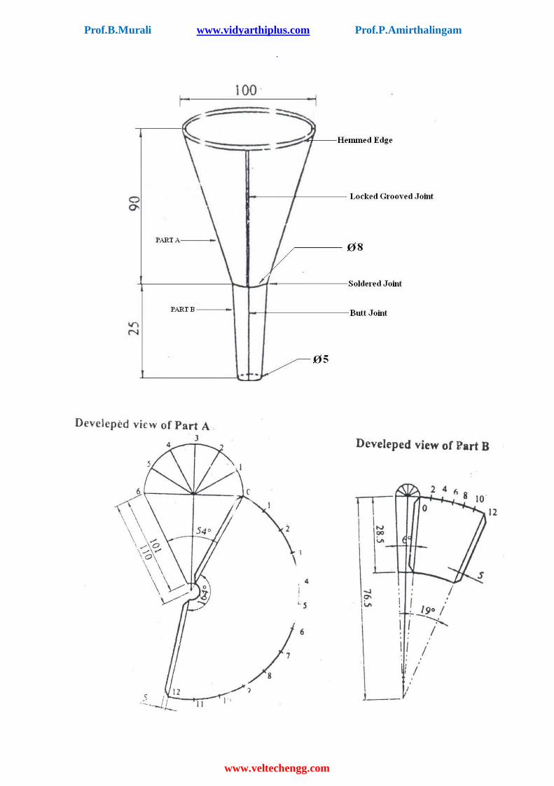
EX.No.8 FUNNEL
Aim: To make a funnel from the given sheet metal.
Material supplied: 22 gauge Galvanized Iron (G.I) sheet.
Tools required: 1. Steel rule 2. Mallet 3. Ball peen hammer 4. Scriber 5. White paper 6. Straight snips 7. Groover 8. Solder
Sequence of operations: 1. Checking 2. Leveling 3. Marking on paper 4. Marking on sheet metal 5. Cutting 6. Folding 7. Hemming 8. Soldering
Working steps: 1. The size of the given sheet metal is checked for its dimensions using a steel rule. 2. The required development of surface is being made on the white paper which is overlapped
on the sheet metal. 3. The marking is done on the sheet metal as per the development being done on the paper. 4. Now using straight snips, unwanted materials are removed. 5. Now fold and bend the work piece to make the funnel shape and joint is made on
the work piece.
6. Then using groover, locked grooved joint is made for about 5mm. Also, hemming is done
in the bottom of the funnel. 7. In between top face and bottom face, butt joints is made using solder. 8. Finally, trimming and finishing operations are being carried out.
Result: Thus the funnel of the required dimensions is made from the given sheet metal.
Prof.B.Murali www.vidyarthiplus.com Prof.P.Amirthalingam
www.veltechengg.com
.
CARPENTRY

Prof.B.Murali www.vidyarthiplus.com Prof.P.Amirthalingam
www.veltechengg.com
.
Structure of Wood
Prof.B.Murali www.vidyarthiplus.com Prof.P.Amirthalingam
www.veltechengg.com
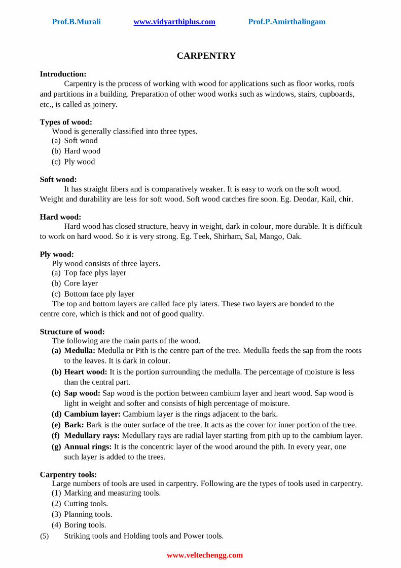
CARPENTRY
Introduction: Carpentry is the process of working with wood for applications such as floor works, roofs
and partitions in a building. Preparation of other wood works such as windows, stairs, cupboards,
etc., is called as joinery.
Types of wood:
Wood is generally classified into three types.
(a) Soft wood (b) Hard wood (c) Ply wood
Soft wood: It has straight fibers and is comparatively weaker. It is easy to work on the soft wood.
Weight and durability are less for soft wood. Soft wood catches fire soon. Eg. Deodar, Kail, chir.
Hard wood: Hard wood has closed structure, heavy in weight, dark in colour, more durable. It is difficult
to work on hard wood. So it is very strong. Eg. Teek, Shirham, Sal, Mango, Oak.
Ply wood:
Ply wood consists of three layers.
(a) Top face plys layer (b) Core layer (c) Bottom face ply layer The top and bottom layers are called face ply laters. These two layers are bonded to the
centre core, which is thick and not of good quality.
Structure of wood:
The following are the main parts of the wood. (a) Medulla: Medulla or Pith is the centre part of the tree. Medulla feeds the sap from the roots
to the leaves. It is dark in colour. (b) Heart wood: It is the portion surrounding the medulla. The percentage of moisture is less
than the central part. (c) Sap wood: Sap wood is the portion between cambium layer and heart wood. Sap wood is
light in weight and softer and consists of high percentage of moisture. (d) Cambium layer: Cambium layer is the rings adjacent to the bark. (e) Bark: Bark is the outer surface of the tree. It acts as the cover for inner portion of the tree. (f) Medullary rays: Medullary rays are radial layer starting from pith up to the cambium layer. (g) Annual rings: It is the concentric layer of the wood around the pith. In every year, one
such layer is added to the trees.
Carpentry tools:
Large numbers of tools are used in carpentry. Following are the types of tools used in carpentry. (1) Marking and measuring tools. (2) Cutting tools. (3) Planning tools. (4) Boring tools.
(5) Striking tools and Holding tools and Power tools.

Prof.B.Murali www.vidyarthiplus.com Prof.P.Amirthalingam
www.veltechengg.com
.

Prof.B.Murali www.vidyarthiplus.com Prof.P.Amirthalingam
www.veltechengg.com
Holding tools:
During the wood working job is shacked, so marking accuracy is tough. To maintain
accuracy the wood is to be held rigidly.
(a) Bench vice:
It is the most common work holding device. It consists of one fixed jaw and one
movable jaw. The fixed jaw is fastened to the work bench. The gap between the jaws
are adjusted using the screw rod.
(b) C-clamps:
It is made up of malleable iron. The operating capacity rates from 50 to
350mm. it can be used for clamping small work. The swivel shoe allows to fix angled
work.
Prof.B.Murali www.vidyarthiplus.com Prof.P.Amirthalingam
www.veltechengg.com
Prof.B.Murali www.vidyarthiplus.com Prof.P.Amirthalingam
www.veltechengg.com
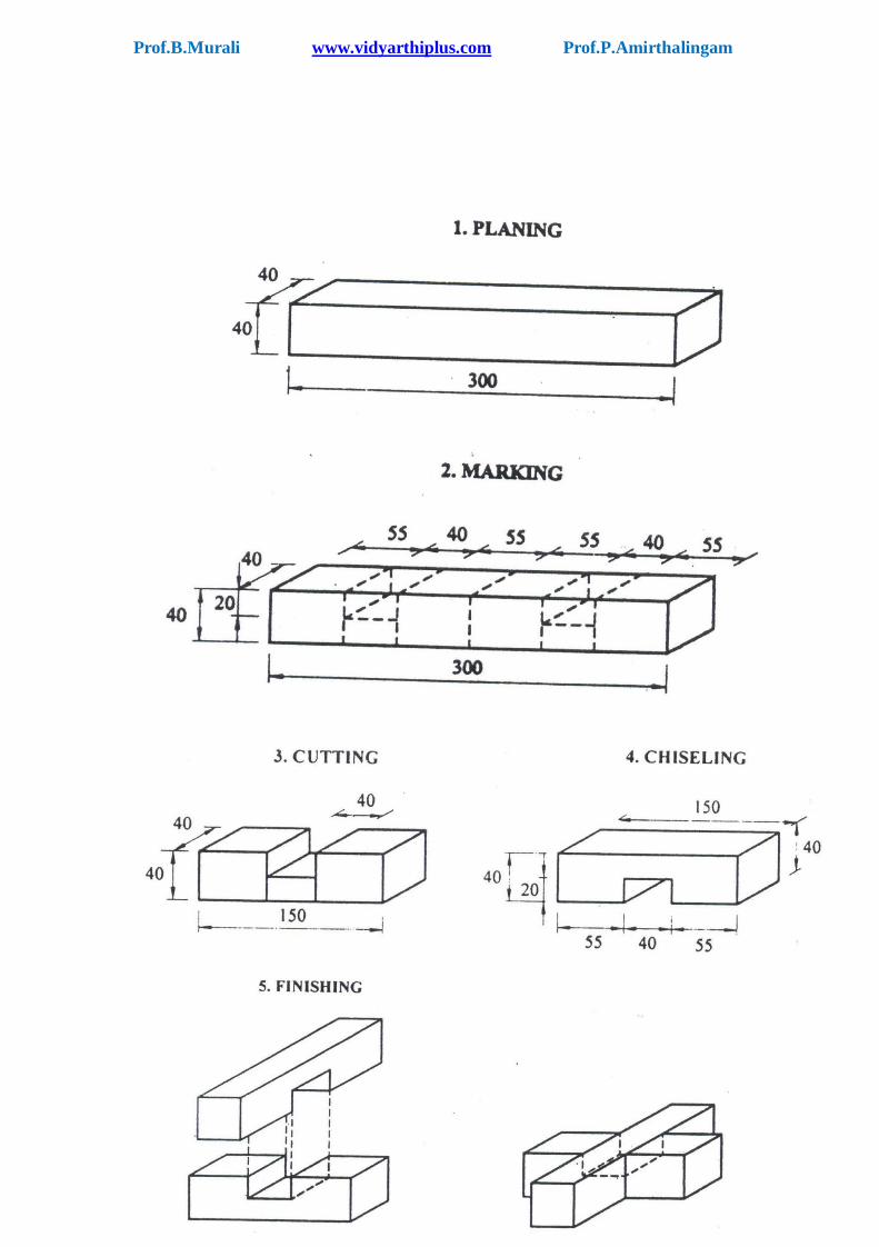
EX.No.9 CROSS LAP JOINT
Aim: To make a cross lap joint from the given wooden piece for the given dimensions.
Material supplied: A wooden piece of size 300 x 40 x 40 mm
Tools required:
1. Steel rule 2. Carpentry vice
3. Jack plane 4. Try square
5. Marking gauge 6. Rip saw
7. Tenon saw 8. Firmer chisel
9. Mallet
Sequence of operation:
1. Rough planning 2. Marking
3. Cutting (or) Sawing 4. Chiseling
5. Finish planning
Working steps: 1. The given job is checked to ensure its correct size. 2. The job is firmly clamped in the carpentry vice and two surfaces are planned by Jack
plane to get right angle. 3. Using try square, the right angle of the work piece is checked. 4. Now all the four sides of the wooden pieces are planned to get the smoother and
finished surface. 5. Now the job is cut into two halves rip saw then proper marking is done for cross lap
joint on the two pieces using steel rule and marking gauge. 6. One half is taken. Using tenon saw and firmer chisel the unwanted portions are removed
as per the drawing. 7. The above procedure is repeated for the other half of the work piece.
8. Jack plane is used to plane the other two faces up to the marked portion. 9. Now the two pieces are assembled to check proper fitting. 10. The finished job is again checked job is again checked for its accurate shape and size
using try square and steel rule.
Result: Thus the desired cross lap joint is obtained.
Prof.B.Murali www.vidyarthiplus.com Prof.P.Amirthalingam
www.veltechengg.com
.

Prof.B.Murali www.vidyarthiplus.com Prof.P.Amirthalingam
www.veltechengg.com
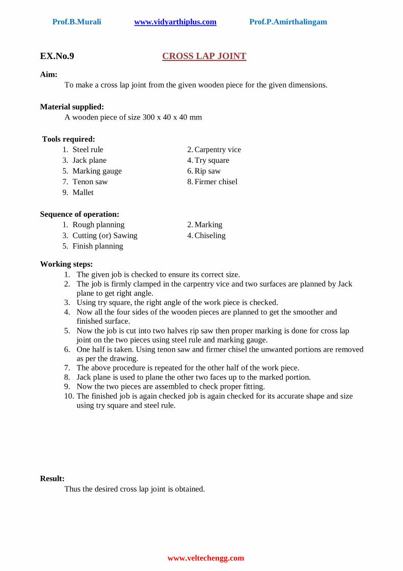
EX.No.10 MORTISE AND TENON JOINT
Aim:
To make a mortise and tenon joint from the given wooden piece for the given dimensions.
Material supplied:
A wooden piece of size 300 x 40 x 40 mm
Tools required:
1. Steel rule 2. Carpentry vice
3. Jack plane 4. Try square
5. Mortise gauge 6. Rip saw
7. Tenon saw 8. Mortise chisel
9. Mallet
Sequence of operations:
1. Rough planning 2. Marking
3. Cutting (or) Sawing 4. Chiselling
5. Finish planning
Working steps:
1. The given job is checked to ensure its correct size. 2. The job is firmly clamped in the carpentry vice and any two surfaces are planed
by jack plane to get right angle. 3. Using try square, the right angle of the work piece is checked. 4. Now all the four sides of the wooden pieces are planed to get the smoother and
finished surface. 5. Now the job is cut into two halves using rip saw then proper marking is done for
mortise and tenon joint on the two pieces using steel rule and marking gauge. 6. One half is taken. Using tenon saw and mortise chisel the unwanted portions are
removed as per the drawing. 7. The above procedure is repeated for the other half of the work piece.
8. Jack plane is used to plane the other two faces upto the marked portion. 9. Now the two pieces are assembled to check proper fitting. 10. The finished job is again checked for its accurate shape and size using try square
and steel rule.
Result:
Thus the desired mortise and tenon joint is obtained.

Prof.B.Murali www.vidyarthiplus.com Prof.P.Amirthalingam
www.veltechengg.com
.
BASIC MACHINING
PROCESS
Prof.B.Murali www.vidyarthiplus.com Prof.P.Amirthalingam
www.veltechengg.com
.

Prof.B.Murali www.vidyarthiplus.com Prof.P.Amirthalingam
www.veltechengg.com
BASIC MACHINING
Introduction: Machining is a process of converting the given workpiece into the required shape and size
with the help of a machine tool. The most widely used machine tool is lathe. There are different types
of tools used in lathe. Several operations can be carried out in the workpiece with the help of lathe. In
simple words, machining is a process of removing certain material from the workpiece.
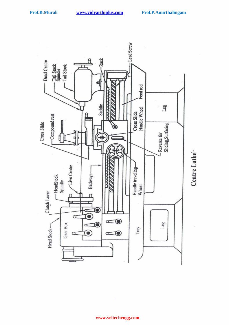
Lathe: Lathe is a machine tool which is used to perform several operations on the workpiece. Lathe is
useful in making several parts which is further assembled to make new machine. Hence lathe is
known as “mother of machines”.
Basic working principle of lathe: In lathe, the work piece is held in the chuck, a work holding device. The cutting tool is
mounted in the tool post. The chuck is rotated by means of power. When the chuck rotates, the work
piece also rotates. The tool is moved against the rotating work piece by giving small amount of depth
of cut. The material is removed in the form of chips. Continuous feed and appropriate depth of cut is
given until the required dimensions of the work piece are obtained.
Types of lathe machines:
There are different types of lathe machines. They are 1. Centre lathe 2. Tool room lathe 3. Bench lathe 4. Capstan lathe 5. Turret lathe 6. Automatic lathe
Work holding devices: 1. Lathe centre
They are used to support work. It has two categories of centre.
(a) Live centre is one which is fitted in the headstock spindle. (b) Dead centre is one which is fitted in the tailstock.
2. Chuck (a) It is a device used to hold a job. It is easily fitted on the thread cut on the end
of headstock spindle. (b) Various types of chuck are
i. Two jaw chuck ii. Three jaw chuck
iii. Four jaw chuck iv. Collet chuck v. Magnetic chuck
3. Face plate (a) It is a circular plate and it is screwed to lathe spindle. (b) It is used for mounting the type of jobs which cannot be held by chucks. (c) There are number of holes and slots on the face of the face plate.

Prof.B.Murali www.vidyarthiplus.com Prof.P.Amirthalingam
www.veltechengg.com
.
Prof.B.Murali www.vidyarthiplus.com Prof.P.Amirthalingam
www.veltechengg.com
4. Catch plate (a) It is a plain disc of steel or cast iron. (b) It is screwed to the nose of the headstock spindle. (c) It is used to drive the work piece through a carrier or dog when it is held between
the centers.
5. Lathe carriers or Dogs (a) It is used for transferring the motion from the rotating driving plate to the work
held between the centres. (b) It is used for connecting end of workpiece to the driving
plate. The types of Dogs are
i. Bent Tail
ii. Straight Tail iii. Clamp Tail
6. Steady Rest
(a) It supports long workpiece when machined between the centres or by a chuck. (b) It is used for cylindrically long
jobs. Two types of steady rest are i. Fixed steady rest
ii. Travelling steady rest
7. Mandrel (a) It is used for holding hollow jobs. (b) It is a hardened piece of round bar for holding bored or reamed jobs. It has drill holes
at both the ends. (c) Work piece is mounted over the mandrel and the mandrel is rotated between centres.
8. Follower rest (a) It is made of cast iron and is used for supporting long slender workpieces, against
the cutting tool forces.
(b) It can be clamped to the carriage of the lathe, to make it travel along with the
cutting tool. (c) It has two adjustable jaws to support the workpiece.
Cutting tools used:
For making a finished job on lathe machine, various types of cutting tools are used. 1. Facing tool
(a) It is used for facing the longitudinal ends of the job. Its shape is like a knife.
2. Rough turning tool (a) It is used to remove excess material from the workpiece in quick time. (b) It can be used to give large depth of cut and works at coarse feed.

Prof.B.Murali www.vidyarthiplus.com Prof.P.Amirthalingam
www.veltechengg.com
.
Prof.B.Murali www.vidyarthiplus.com Prof.P.Amirthalingam
www.veltechengg.com
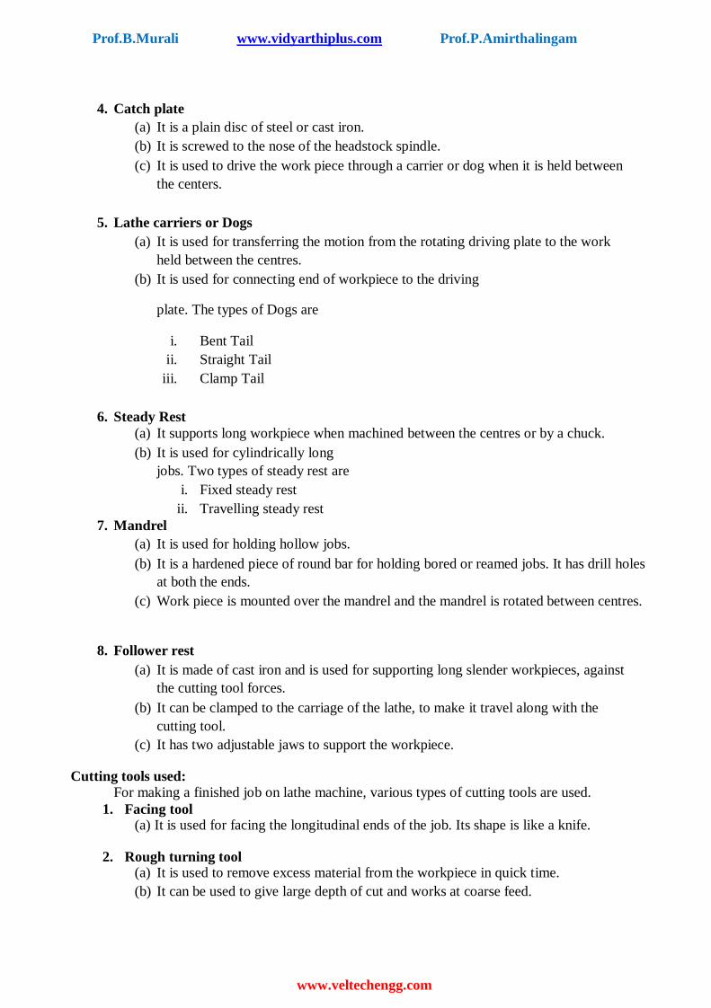
Lathe operations: 1. Plain turning
(a) It is done for reducing the diameter of the workpiece.
(b) A cutting tool with 700 setting angle is used for roughing operation.
(c) More feed is given for rough turning while less feed is given for finishing. (d) Work piece is held in chuck and tool is set to the centre height of the workpiece.
2. Taper turning (a) Taper turning is different from the turning operation. (b) Taper is defined as the uniform change in the diameter of a workpiece measured
along its length.
Taper = (D-d) / L
Where,
D is large diameter
d is small diameter
L is length of tapper
After Machining
Prof.B.Murali www.vidyarthiplus.com Prof.P.Amirthalingam
www.veltechengg.com
.
EX.No.11 FACING, TURNING, STEP TURNING, CHAMFERING AND TAPER
TURNING
Aim:
To obtain the required shape and size of the workpiece by turning and facing operations.
Material supplied:
Cylindrical work piece of dia 35mm and length 112mm mild steel rod.
Tools required:
1. Lathe 2. Cutting tool 3. Vernier caliper 4. Try square 5. Scriber 6. Vernier height gauge
Sequence of operations:
1. Checking 2. Work piece setting 3. Tool setting 4. Facing 5. Turning 6. Taper turning 7. Chamfering
Working steps:
1. The given workpiece is checked for its dimensions. 2. The workpiece is held in the chuck. Chuck key is used to tighten the job firmly,
ensuring centering of workpiece. 3. The single point cutting tool is held in the tool post and tighten the nuts using spanner. 4. Facing is done with cutting tool moving from the centre of the workpiece towards outside. It
is done until the required length of the job is obtained. 5. Turning is done to reduce the diameter of the job. Sufficient depth of cut is given and it is
done until the required diameter of the job is obtained. 6. Next the taper turning is done on the workpiece, as per the taper angle already calculated.
Then the compound rest base is swivelled and set at half taper angle. Cutting tool is moved at
an angle to the lathe axis. Tool is moved by the compound rest hand wheel.
7. For chamfering to be done at the end of workpiece, the tool is held at 45° to the lathe axis
and it is fed against the rotating workpiece. 8. Finally, the dimensions of the workpiece are again checked.
Result:
Thus the required size and shape of the given work piece is obtained.
Prof.B.Murali www.vidyarthiplus.com Prof.P.Amirthalingam
www.veltechengg.com
Before Machining
After Machining

Prof.B.Murali www.vidyarthiplus.com Prof.P.Amirthalingam
www.veltechengg.com
.
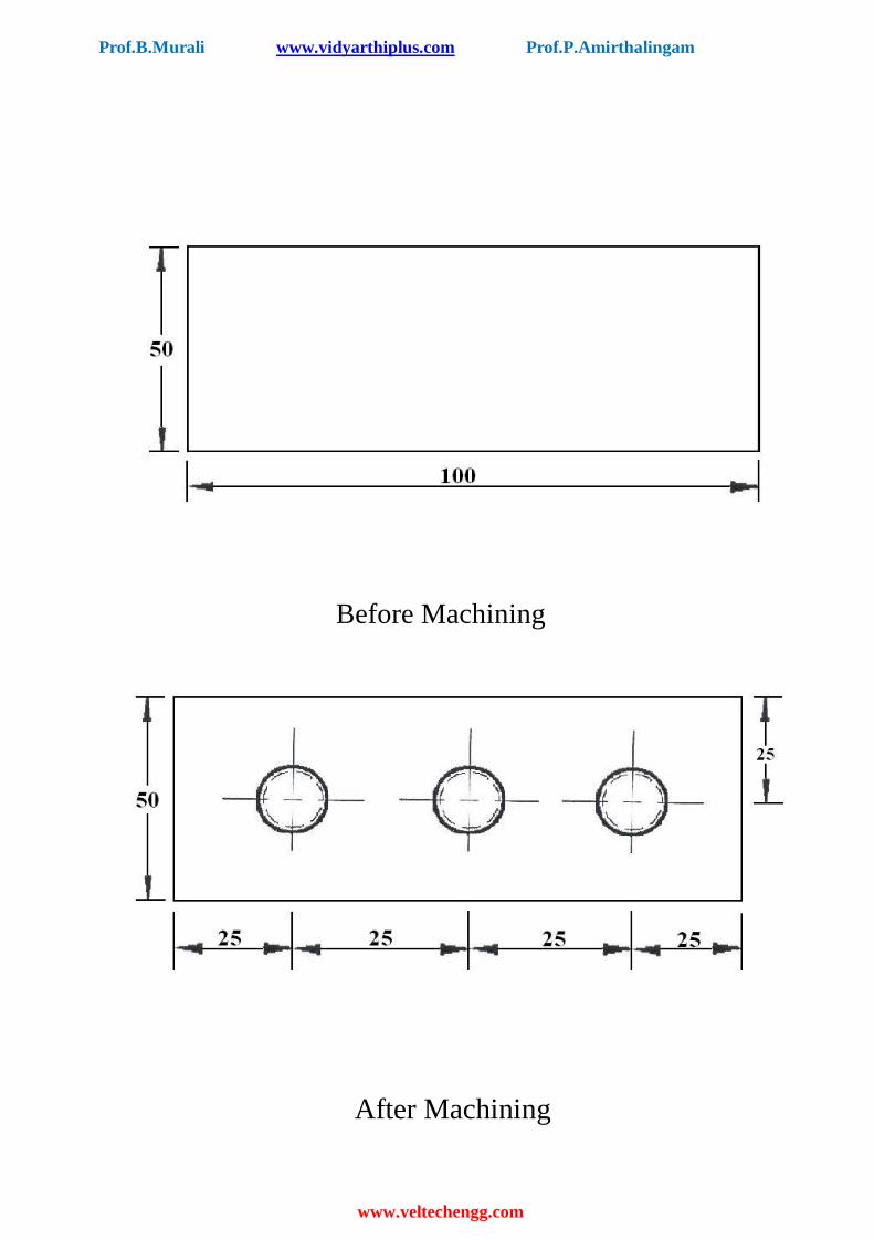
EX.NO.12 DRILLING AND TAPPING
Aim: To drill the holes of required size and tap the drilled hole.
Material supplied: 50 x 50 x 5mm Mild steel plate – 1 No.
Tools required: 1. Bench vice 2. Machine vice 3. Steel rule 4. Standard set of filling tools 5. Try square 6. Surface plate 7. Vernier height gauge 8. Scriber 9. Dot punch 10. Drill bit 11. Drilling machine 12.Tap set with Die holder.
Sequence of operations:
1.Checking 2.Filling 3.Marking 4.Punching 5.Drilling 6.Tapping
Working steps: 1.The raw material is checked for its size 50 x 50 x 5mm using steel rule. 2.The given workpiece is clamped in a vise and any two surfaces are filled to get right angle . 3.Chalk is applied uniformly on the surfaces of the workpieces. 4.With the help of vernier height gauge, surface plate, angle plate steel rule and scriber the
given dimensions are marked. 5.The midpoint of the required holes is punched by using a dot punch. 6.The punched dots are drilled by drilling machine. 7.After drilling the holes, they are tapped by using tap set. 8.Finally, the dimensions of the workpiece are again checked.
Result:
Thus the given workpiece is drilled and tapped to the required dimensions.
Prof.B.Murali www.vidyarthiplus.com Prof.P.Amirthalingam
www.veltechengg.com
STUDY NEXERCISES

Prof.B.Murali www.vidyarthiplus.com Prof.P.Amirthalingam
www.veltechengg.com
.
CENTRIFUGAL PUMP

Prof.B.Murali www.vidyarthiplus.com Prof.P.Amirthalingam
www.veltechengg.com
.
Ex.No.1 STUDY OF CENTRIFUGAL PUMP
Introduction:
The pump is a hydraulic machine which converts the mechanical energy into hydraulic energy
in the form of pressure. The Centrifugal pump is a hydraulic machine which convert the mechanical
energy into pressure energy by means of centrifugal force.
Working principle:
The centrifugal pump works on the principle of Forced Vortex Flow which means that when a
certain mass of liquid is rotated by an external torque, the rise I pressure head of the rotating liquid
take place. The rise in the pressure head at any point of the rotating liquid is proportional to the square
of tangential velocity of the liquid at that point.
Main parts of Centrifugal pump:
The followings are the main parts of a centrifugal pump,
1. Sunction pipe 2. Impeller
3. Casing 4. Delivery pipe.
All the main parts of the centrifugal pump are shown in the following figure.
1. Suction pipe A pipe whose one end is connected to inlet of the pump and other end dips into the
water sump is known as suction pipe. A foot valve which is a non- return valve or one-
way type of valve is fitted at the lower end of the suction pipe. A strainer is also fitted
at the lower end of the suction pipe for filtering purpose.
2. Impeller The rotating part of a centrifugal pump is known as Impeller. It contains series of
curved vanes. The Impeller is mounted on a shaft which is connected to the shaft of an
electric motor which runs the pump.
3. Casing Casing is an air- tight passage surrounding the impeller and is designed such a way that
the kinetic energy of the water discharge at outlet of the impeller is converted into
pressure energy before the water leaves the casing and enter into delivery pipe. Three
common types of casings are,
i. Volute casing
ii. Vortex casing iii. Diffuser casing
4. Delivery pipe: A pipe whose end is connected to outlet of the pump and the other end delivers the
water at required level is known as Delivery pipe.

Prof.B.Murali www.vidyarthiplus.com Prof.P.Amirthalingam
www.veltechengg.com
Working of Air conditioner .

Prof.B.Murali www.vidyarthiplus.com Prof.P.Amirthalingam
www.veltechengg.com
EX.NO.2 STUDY OF AIRCONDITIONER
Introduction: An air conditioner is defined as an assembly of different parts of the system used to produce a
specified condition of air within required space or building below that of atmosphere or surroundings. An ideal air- conditioner should maintain correct temperature, humidity and air- movement etc.
Generally a small distance air- conditioning plant having the capacity of 0.5 ton. In a window air-
conditioner all the components are located in a box.
Mechanism: An air- conditioning system works on vapour compression cycle. This cycle works in
following four phases. 1. Compression
2. Condensation 3. Expansion and
4. Evaporation 1. Compression Compression takes place at the compressor. The low pressure, low temperature dry refrigerant
or coolant vapour is drawn from the evaporator into compressor cylinder during suction stroke
of the compressor. During compression stroke pressure and temperature of the vapour
increases until the vapour temperature is greater than the temperature of condenser cooling
medium (Air or water). This high pressure and high temperature vapour passes out to the
condenser through discharge line.
2. Condensation In the condenser high pressure and high temperature refrigerant vapour rejects heat to cooling
medium thus allowing the vaporized refrigerant to return to liquid state.
3. Expansion After condenser, the liquid refrigerant is stored in the liquid receiver until needed. Then it is
passes through an expansion device (i.e. Expansion valve). Due to the expansion the high
pressure reduce very much to allow the vaporization of liquid at very low temperature of about
-100 C.
4. Evaporation Then the low pressure low temperature refrigerant vapour enters into the evaporator. Where a
considerable amount of heat is absorbed from the surrounding by the refrigerant. After
absorbing heat from the surrounding, the liquid refrigerant changes to vapour state. Then the
refrigerant vapour again move into compressor through the suction line. Again the vapour
compression cycle is repeated.
Boiling point of a refrigerant is very low. The refrigerant absorbs heat from one place and
release it to the other place. Generally Freon 12 is used as a refrigerant in domestic air-
conditioner. It is observed that all the chloro fluro carbons (CFC) including Freon affects the
ozone layer causing global warming. Since now-a-days the newly invented refrigerant Hydro
Fluoro Carbon (HFC) is used as refrigerant.
Main parts of an air- conditioner The followings are the main parts of an air- conditioner
Compressor Condensor Expansion device & Evaporator and Fan
Prof.B.Murali www.vidyarthiplus.com Prof.P.Amirthalingam
www.veltechengg.com
.
SMITHY
DEMONSTRATION
EXERCISES

Prof.B.Murali www.vidyarthiplus.com Prof.P.Amirthalingam
www.veltechengg.com
.

Prof.B.Murali www.vidyarthiplus.com Prof.P.Amirthalingam
www.veltechengg.com
SMITHY
Introduction:
Smithy is one of the manufacturing processes in which the metals are processed to get the
desired size and shape by applying the mechanical force or by heating the metal and then applying
smaller of force. Black smithy or hard forging is an ancient trade. It is employed only for relatively
small components where huge is to be applied. Normally the heating of metal is done in open fire or
hearth (it is like a small furnace). The fuel used for furnace may be coke/coal or charcoal.
Tools used in Smithy shop:
Tools used in smithy is broadly classified as follows, Supporting tools, Striking tools, Holding tools, Cutting tools, Finishing and shaping tools
1. Supporting tools
Anvil It is most often used smithy tool without which we cannot carry out any smithy
process. It is used as a support when hammering is performed. It is made up of solid wrought
Swage block It is used for squaring, sizing, heading, bending, and forming operation.It may be
used either flat or edgewise in its position.
2. Striking tools
Two different types of hammers are used in forging operations. Hand hammers
These hammers are classified as Ball peen hammer, Straight peen hammer and Cross peen hammer.
Sledge hammer It is used for heavy work only. It is flat end on both sides. The weight varies
from 4.5 to 5.5 kg for ordinary work and around 9 kg for heavy work.
3. Holding tools
Generally tongs are used for holding purpose. It is made up of mild steel.
Types of Tongs used are Tong, Flat Gad Tong, Ring Tong and Straight- lip fluted Tong
4.
Cutting tools
It is cutting and necking and metals prior to breaking. Two types of chisel are normally
used.
Cold chisel and Hot chisel
i. Cold chisel:
It is made up of tool steel with a cutting angle of about 600 and its edge is
hardened and tempered. ii. Hot chisel:
It is made up of low carbon steel and has a cutting angle of 300 . Its edge does
not require hardening.

Prof.B.Murali www.vidyarthiplus.com Prof.P.Amirthalingam
www.veltechengg.com
5. Finishing and shaping tools
These tools are used to give the desired forms and shapes.
Swages
1. Swages are used for wok which has to be reduced and finished to round, square or
hexagonal form.
2. It is made up of high carbon steel.
3. The swages may be in separate top and bottom halves.
1. It is used after the job has been forged into shape with a hammer and the hammer
marks can be seen on the job surface.
2. It is used to achieve better finish surface especially when surface area is large.
3. It is provide smoothness and accuracy to the job or work.

Prof.B.Murali www.vidyarthiplus.com Prof.P.Amirthalingam
www.veltechengg.com
.
EX No : 1 MAKING A ROUND ROD INTO HEXAGONAL HEADED BOLT
Aim :
To make a hexagonal headed bolt of size 10*9 mm on one end of the round rod. (Length of
the rod to be made is 50mm).
Material Supplied:
M S Round rod of diameter 10mm and length to be calculated (refer calculation).
Tools required:
1. Blacksmith furnace.
2. Tongs. 3. Anvil.
4. Swage block. 5. Sledge hammer.
6. Flatter. 7. Other relevant tools.
Sequence of operations:
1. Heating.
2. Flattering. 3. Forming hexagonal shape.
4. Checking. 5. Cooling.
Working steps:
1. First length of the given work piece is calculated and it is selected for operation. 2. Using tongs, the end of the work piece is kept in the smith furnace to attain to raise
the temperature to red hot condition. 3. Now the work piece is taken from the furnace and kept in the hole of the anvil for
further processing. 4. The hammering process is carried out to flatten the one end of the work piece. 5. Again it is heated and using flatter it is converted into a square headed bolt.
6. After that any two corner are hammered to form hexagonal bolt head. 7. Now the work piece is cooled using water to avoid deformation and to attain the
maximum hardness.
Result :
Thus the hexagonal headed bolt is made from the given round rod.

Prof.B.Murali www.vidyarthiplus.com Prof.P.Amirthalingam
www.veltechengg.com
FOUNDRY
Prof.B.Murali www.vidyarthiplus.com Prof.P.Amirthalingam
www.veltechengg.com
.
FOUNDRY

Prof.B.Murali www.vidyarthiplus.com Prof.P.Amirthalingam
www.veltechengg.com
FOUNDRY Introduction:
Producing components by casting has been since the earliest day of civilization. Lot of shape
and sizes can be prepared in a casting process. To make the casting of components, a cavity of
desired shape made in moulding sand or other material. The process of moulding consists of all
operations done to make a mould. Pattern: Pattern is the model used to get required casting. It is used to produce to mould cavity
in sand.
Foundry: The place where moulding and castings are done is known as foundry.
Moulding sand or Green sand: It is mixture of sand and additives such as water,
bentonite, inoculent, sodium silicate etc., used to create mould cavity.
Components required for moulding The following components are essential for producing mould, Moulding Sand (Green
sand), Moulding Boxes, Pattern, Moulding tools.
I. Moulding Sand
It is a special type of sand used for making mould. Moulding sand has three constitutes. They are,Sand, Binder, Additive.
Properties of moulding sand
A good moulding sand must have the following properties. Porosity or permeability Plasticity Adhesiveness Cohesiveness Refractoriness
II. Moulding Boxes Moulding box is also called moulding flask. It is a frame or box of wood or metal. Wood
is cheaper boxes made quickly. Wood wears out quickly. It is destroyed by contact with hot metal.
Metal boxes in steel, cast iron and aluminum alloys are used in mass production. Moulding boxes
are used for making sand moulds. Moulding flasks may have two or more parts. The main type of
flasks are:
a) Snap Flask
b) Tight or Box Flash III. Patterns
A pattern is the replica of the desired casting used to produce a mould cavity into which
liquid metal is poured. When patter packed in a suitable material produces a cavity called the mould.
This cavity when filled with molten metal produces the desired casting.
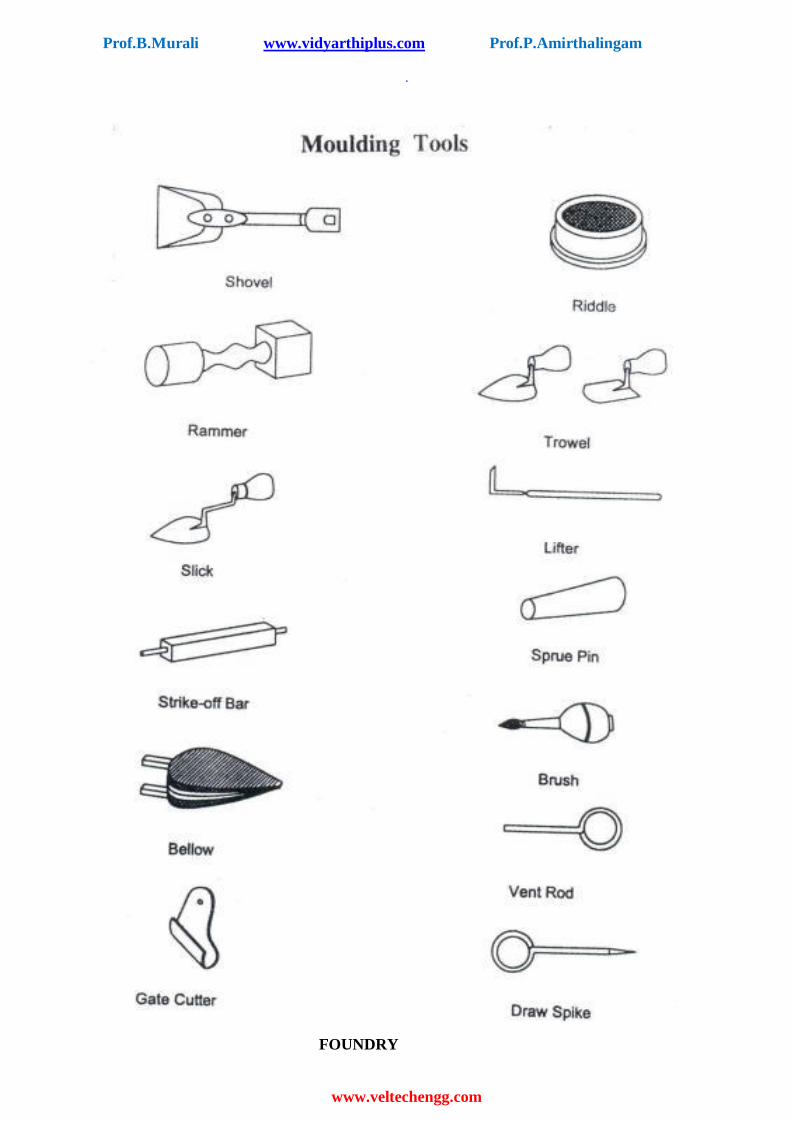
IV. Moulding tools
1) Shovel 8) Bellows
2) Riddle 9) Swab
3) Rammer 10) Gate cutter
4) Trowels 11) Draw spike
5) Slick 12) Lifter
6) Strike off bar 13) Vent rod
7) Sprue pin

Prof.B.Murali www.vidyarthiplus.com Prof.P.Amirthalingam
www.veltechengg.com
.
Prof.B.Murali www.vidyarthiplus.com Prof.P.Amirthalingam
www.veltechengg.com
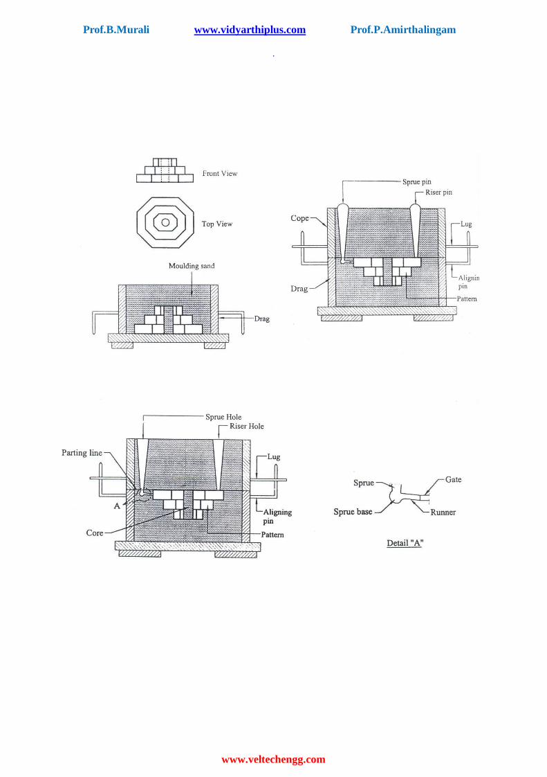
EX.NO.2
Aim :
GEAR
To make the mould of a Gear pattern.
Material Supplied:
Moulding sand, Parting sand, Facing sand, Gear pattern, Moulding boxes etc.
Tools required:
1. Showel 2. Sieve 3. Trowel 13. Bellow
4. Rammers 5. Spure pin 6. Strike off bar
7. Lifter 8. Gate cutter 9. Runner
10. Riser 11. Vent rod 12. Draw spike
Sequence of operations:
1. Sand preparation. 2. Core preparation.
3. Placing the pattern on moulding board. 4. Ramming of drag.
5. Placing runner and riser. 6. Ramming of cope.
7. Removal of pattern, runner, riser. 8. Gate cutting.
Working steps :
1. The gear pattern is placed on the moulding board. 2. A suitable core is prepared and placed in the hole of gear pattern.
3. Clay washing is done inside the drag surface. 4. Parting sand is applied over the pattern. 5. Box is filled with smooth moulding sand and proper ramming is done using flat and
peen rammers. 6. Excess sand is removed using the strike off bar.
7. The drag is turned upside down. 8. The cope is placed on the drag after doing clay wash.
9. The runner and riser are placed over the pattern. 10. After applying parting sand, moulding sand is filled over the pattern.
11. Ramming is done to get a rigid mould. 12. Using strike off bar excess sand is removed.
13. Vent holes are made using vent rod. 14. Runner and raiser are removed a funnel shape is made on the runner hole.
15. Cope is kept aside and the pattern is removed using draw spike. 16. The cope is placed on the drag.
Result :
Thus the gear mould is prepared and ready for casting.
Prof.B.Murali www.vidyarthiplus.com Prof.P.Amirthalingam
www.veltechengg.com
.
Prof.B.Murali www.vidyarthiplus.com Prof.P.Amirthalingam
www.veltechengg.com
EX No :3 STEPPED CONE PULLEY
Aim :
To make the mould of a flange pattern.
Material Supplied :
Moulding sand, Parting sand, Facing sand, Stepped cone pulley pattern, Moulding boxes etc.
Tools required:
1. Showel 2. Sieve 3. Trowel 13. Bellow
4. Rammers 5. Spure pin 6. Strike off bar
7. Lifter 8. Gate cutter 9. Runner
10. Riser 11. Vent rod 12. Draw spike
Sequence of operations:
1. Sand preparation.
2. Core preparation. 3. Placing the pattern on moulding board.
4. Ramming of drag. 5. Placing runner and riser.
6. Ramming of cope. 7. Removal of pattern, runner, riser.
8. Gate cutting.
Working steps :
1. The gear pattern is placed on the moulding board. 2. A suitable core is prepared and placed in the hole of gear pattern.
3. Clay washing is done inside the drag surface. 4. Parting sand is applied over the pattern. 5. Box is filled with smooth moulding sand and proper ramming is done using flat and
peen rammers. 6. Excess sand is removed using the strike off bar. 7. The drag is turned upside down.
8. The cope is placed on the drag after doing clay wash. 9. The runner and riser are placed over the pattern.
10. After applying parting sand, moulding sand is filled over the pattern. 11. Ramming is done to get a rigid mould.
12. Using strike off bar excess sand is removed. 13. Vent holes are made using vent rod.
14. Runner and raiser are removed a funnel shape is made on the runner hole. 15. Cope is kept aside and the pattern is removed using draw spike.
16. The cope is placed on the drag.
Result :
Thus the flange mould is prepared and ready for casting.

Prof.B.Murali www.vidyarthiplus.com Prof.P.Amirthalingam
www.veltechengg.com
FITTING

Prof.B.Murali www.vidyarthiplus.com Prof.P.Amirthalingam
www.veltechengg.com
.
Prof.B.Murali www.vidyarthiplus.com Prof.P.Amirthalingam
www.veltechengg.com
FITTINGS
Introduction:
Fitting is the assembling together of parts and removing metals to secure the necessary fit and
it may or may not be carried out at the bench. An operator who does the fitting job is called fitter and
the work done by him is fitting. There are various group of fitters such as bench fitter, assemble fitter
and erection fitter etc.
Fitting tools
The fitting tools are classified into following groups
1) Work holding tools 2) Marking and Measuring tools
3) Cutting tools 4) Finishing tools
5) Other tools 1) Work holding tools:
a. Bench Vice b. C- clamp
c. V- block with clamp 2) Marking and Measuring tools:
a. Steel rule h. Try Square
b. Caliper i. Trammel
c. Vernier Caliper j. Dot punch
d. Vernier height guage k. Surface plate
e. Jenney Caliper (or) Hermaphrodite l. Angle plate
f. Scriber m. Surface gauge
g. Divider 3) Cutting tools:
a. Hacksaw Frame Solid frame (length cannot be changed) Adjustable frame (length can be changed)
b. Chisel 4) Finishing
tools: File
It is principal hand tool used by fitter. It has several teeths to remove fine chips of materials.
a. Flat file b. Square file c. Round file
d. Half round file e. Triangular file (or) three square file
f. Knife edge file 5) Other tools
a. Ball- peen hammer b. Screw driver

Prof.B.Murali www.vidyarthiplus.com Prof.P.Amirthalingam
www.veltechengg.com
.
Prof.B.Murali www.vidyarthiplus.com Prof.P.Amirthalingam
www.veltechengg.com
EX No : 4 SQUARE FITTING
Aim :
To file the given workpiece (mild steel) into square shape.
Material Supplied :
Moulding sand, Parting sand, Facing sand, Stepped cone pulley .
Tools required :
1. Showel
2. Steel rule 3. Standard set of filing tools
4. Try square 5. Vernier height gauge
6. Surface plate 7. Dot punch
Sequence of operations:
1. Checking.
2. Marking. 3. Punching.
4. Rough filing. 5. Finish filing.
Working steps:
1. The dimension of the given work piece (job) is checked using steel rule. 2. Job is rigidly fixed on a bench vice and the two adjacent sides are filed using a flat file so
that they at right angles. 3. Then chalk is applied uniformly on the surface of the work piece.
4. The given dimensions are marked by using vernier height gauge with reference to the datum. 5. Then using dot punch, dots are punched along the marked line. 6. The work piece is again fitted on the bench vice and the other two sides are filed in the
same manner. 7. Finally the required square shape is obtained by filing repeatedly using smooth and
triangular file so that the given dimension is obtained.
Result :
Thus the Square filing is done on the given work piece.

Prof.B.Murali www.vidyarthiplus.com Prof.P.Amirthalingam
www.veltechengg.com

Prof.B.Murali www.vidyarthiplus.com Prof.P.Amirthalingam
EX No : 5 V- JOINT
Aim :
To make a V- Joint on the given workpieces.
Material Supplied :
50 * 50 * 50 mm Mild steel plate - 2 Nos
Tools required :
1. Bench vice
2. Steel rule 3. Standard set of filling tools
4. Try square 5. Scriber
6. Vernier height gauge 7. Surface plate
8. Angle plate 9. Dot punch
10. Fixed hacksaw
Sequence of operations :
1. Checking 2. Rough filling 3. Marking
4. Punching 5. Sawing 6. Rough Filling
7. Finish Filling
Working steps :
1. The raw material is checked for its size 50*50*5 mm after deburring. 2. A given pieces are fixed rigidly on the vice separately and all edges are filed using flat file so that they are at right angles. 3. Then chalk is applied uniformly on the surface of the work pieces. 4. The work piece is marked to given dimensions as per drawing with reference to the datum using surface plate and vernier height gauge.
5. Now using dot punch, dots are punched along the marked line. 6. Using hacksaw frame, the unwanted portions are removed.
7. Cutting edges are filed by half round and triangular files. 8. Finally the assembly is checked for the required class of fit.
Result :
Thus the required V- Joint is obtained from the given work piece.

Prof.B.Murali www.vidyarthiplus.com Prof.P.Amirthalingam
VIVA-VOCE
PLUMBING
1. What is plumbing?
2. What is the purpose of plumbing?
3. What are the different types of pipes commonly used?
4. State the different types of pipe fittings used.
5. State the difference between the elbows and bend? Where are they recommended?
6. State the purpose of die cast?
7. What is the difference between union and coupling?
8. What is the advantage of flange joint?
9. In a piping connection, the number of bends should be kept to a minimum. Why?
10. What is the difference between a gate and a tap?
11. State the different types of gates commonly used.
12. What is the instrument used to form the thread on the pipes.
13. Name some holding tools used in plumbing.
14. What are flexible pipes? What are their uses?
CARPENTRY
15. What is carpentry?
16. Name few types of timbers and some examples for each type.
17. What are the instruments used for measuring in carpentry?
18. What are the different types of joints in carpentry?
19. What is the use of try square?
20. State the difference between mitre square and bevel square.
21. What is the use of Calipers?
22. How is the work piece held during working?
23. What is setting of saw teeth?
24. What are the different types of saw?

25. What are different types of chisel?
26. What is the difference between hammer and a mallet?
WELDING
27. Define welding
28. Say different types of welding.
29. What is the temperature obtained in gas and arc welding?
30. List the equipments needed to carry out welding operation.
31. Which type of welding (Gas / Arc) you prefer/
32. What are the necessary precautions you have to take while welding?
33. Why you should not see the flame during the welding operation?
34. What are the two gases used in gas welding?
35. What are the different types of joints, you make in the lab?
36. What is the difference between riveting and welding?
37. What is gas welding?
38. What is arc welding?
39. What is electrode?
40. Say the polarities of work piece and electrode?
41. Name the material used for coating on electrode.
42. Why flux is added during welding?
43. How do welding is different from machining?
44. How lap joint is performed?
45. How butt joint is performed?
46. Why tag weld is done during welding
MACHINING
47. What do you mean by machining?
48. Name the tools used in machining processes?
49. List the parts of lathe?
50. What are the operations can be performed on lathe?
51. Why turning operation is done?
52. Why facing operation is done?
53. Give the formula for taper turning?
54. Why chamfering is done?
55. What is knurling?
56. What is the material used for cutting tool and work piece in your lab?
SHEET MEAL
57. Define sheet metal.
58. What is the tool is used to measure the thickness of sheet metal?
59. What do you mean by gauge?
60. Name the various tools used in sheet metal
61. What is the application of sheet metal?
62. List the operation used in sheet metal.
63. What are the metals used for sheet metal work?
64. What is bending?
65. What is punching?
66. Why anvil is needed?
MACHINE ASSEMBLY PRACTICE
67. What is the principle of centrifugal pump?
68. Why pumps are used?
69. List the different components of centrifugal pump.
70. What is priming?
71. What are the different types of casings in centrifugal pump?
72. What is air conditioner?
73. What are the two types of Air conditioner?
74. Which type of Air conditioner do you prefer? Why?
75. List the parts of Air conditioner
76. What is refrigerant?
77. What is meant by smithy?
78. Name the tools used in smithy?
SMITHY

79. What is the importance of swage block in smithy?
80. What are the operations involved in smithy?
81. What is upsetting?
82. What is forging?
83. What is function of flatter?
84. What is fullering?
85. Why tongs are required?
FOUNDRY
87. What is foundry?
88. What is pattern?
89. List the foundry tools?
90. What is gate?
91. What is vent rod?
92. Name the types of moulding boxes.
93. What is casting process?
94. Give the application of casting.
95. What do you mean by green sand?
96. Why ramming is done?
FITTING
97. What is meant by fitting?
98. Name the fitting tools.
99. Name the joints that can be made using fitting.
100. What is the function of files?
101. List the types of files
102. What is a plier?
103. List the different types of punches.
104. What is the function of steel rule?
105. List the measuring tools used in fitting?
106. What is importance of bench vice?
