development of a formula sae body 25% report 2 1. introduction 1.1 problem statement the florida...
TRANSCRIPT
Fall 2012
EML 4551 Senior Design Project
A B.S. THESIS PREPARED IN PARTIAL FULFILLMENT OF THE
REQUIREMENT FOR THE DEGREE OF BACHELOR OF SCIENCE
IN MECHANICAL ENGINEERING
Development of a Formula SAE Body 25% Report
Javier Gutierrez Angel Nuñez
Diego Quintero
Advisor: Professor Andres Tremante
November 7, 2012
This B.S. thesis is written in partial fulfillment of the requirements in EML 4551. The contents represent the opinion of the authors and not the
Department of Mechanical and Materials Engineering.
Page ii
Ethics Statement and Signatures
The work submitted in this B.S. thesis is solely prepared by a team consisting of Javier
Gutierrez, Angel Nuñez, and Diego Quintero and it is original. Excerpts from others’ work
have been clearly identified, their work acknowledged within the text and listed in the list
of references. All of the engineering drawings, computer programs, formulations, design
work, prototype development and testing reported in this document are also original and
prepared by the same team of students.
Javier Gutierrez
Team Leader
Angel Nuñez
Team Member
Diego Quintero
Team Member
Dr. Andres Tremante
Faculty Advisor
Page iii
Table of Contents
Ethics Statement and Signatures ................................................................................................. ii
Table of Contents .......................................................................................................................... iii
List of Figures ................................................................................................................................ v
List of Tables ................................................................................................................................. vi
Abstract .......................................................................................................................................... 1
1. Introduction ............................................................................................................................ 2
1.1 Problem Statement .......................................................................................................... 2
1.2 Motivation ......................................................................................................................... 3
1.3 Literature Survey ............................................................................................................. 3
2. Project Formulation ............................................................................................................... 6
2.1 Project Objectives ............................................................................................................ 6
3. Design Alternatives ................................................................................................................ 6
3.1 Overview of Conceptual Designs Developed .................................................................... 6
3.2 Design Alternate I ............................................................................................................. 7
3.3 Design Alternate II ........................................................................................................... 7
3.4 Design Alternate III .......................................................................................................... 8
3.5 Feasibility Assessment .................................................................................................... 9
3.6 Proposed Design ............................................................................................................ 10
4. Project Management ............................................................................................................ 11
4.1 Overview ......................................................................................................................... 11
4.2 Breakdown of Work into Specific Tasks ......................................................................... 11
4.3 Organization of Work and Timeline ................................................................................ 12
4.4 Breakdown of Responsibilities ........................................................................................ 13
5. Engineering Design and Analysis ........................................................................................ 14
5.1 Analytical Analysis ......................................................................................................... 14
Page iv
5.1.1 Body Analysis ................................................................................................................. 14
5.1.2 Side Pod Analysis ........................................................................................................... 15
5.1.3 Ground Effect Analysis................................................................................................... 15
5.2 Structural Design............................................................................................................ 16
5.3 Cost Analysis ................................................................................................................... 18
6. Prototype Construction ....................................................................................................... 20
6.1 Description of Prototype ............................................................................................... 20
6.2 Prototype Cost Analysis ................................................................................................. 21
7. Testing and Evaluation ........................................................................................................ 22
7.1 Overview ......................................................................................................................... 22
8. Conclusion ............................................................................................................................. 23
8.1 Conclusion and Discussion ............................................................................................ 23
9. References ............................................................................................................................. 24
10. Appendices ......................................................................................................................... 26
Appendix A. Formula SAE Body Rule Book ........................................................................... 26
Page v
List of Figures
Figure 1: 2011-2012 FIU-FSAE Prototype .................................................................................................. 2
Figure 2: GPR 2011-2012 Vehicle ................................................................................................................... 3
Figure 3: Design Alternative 1 ......................................................................................................................... 7
Figure 4: Design Alternative 2 ......................................................................................................................... 8
Figure 5: Design Alternative 3 ......................................................................................................................... 8
Figure 6: Proposed Design.............................................................................................................................. 10
Figure 7: Gantt chart ......................................................................................................................................... 12
Figure 8: Air Flow .............................................................................................................................................. 15
Figure 9: Ground Effects .................................................................................................................................. 16
Figure 10: Structural Design .......................................................................................................................... 17
Figure 11: Prototype ......................................................................................................................................... 20
Figure 12: Desired Design............................................................................................................................... 23
Page vi
List of Tables
Table 1: Competition Events [10] ................................................................................................................... 5
Table 2: Breakdown of Responsibilities .................................................................................................... 13
Table 3: Cost Analysis [7] ................................................................................................................................ 18
Table 4: Current Hours Spent ........................................................................................................................ 19
Table 5: Prototype Cost Analysis [6] .......................................................................................................... 21
Page 1
Abstract
A body for the Florida International University (FIU), Formula SAE team latest
prototype with the proper studies and analysis will be developed, taking into account
several factors to present an optimum body model as a final result. These factors include,
but are not limited to, weight, cost, drag resistance, functionality and esthetics.
The following project is divided into three phases, design (or modeling), analysis and
manufacture. First, on the design stage, a rough hand sketch of the vehicle will be made.
Then, a mock-up of the vehicle body will be modeled in SolidWorks. Subsequently, several
iterations of shapes and sizes are going to be modeled. Finally, a design will be chosen and
the final optimization will be performed. For phase two, testing, initially the body design
will be tested using CAD software. Afterwards, several shapes and profiles will be analyzed.
Finally, the physical body will be tested in a wind tunnel. For the third stage, manufacture,
first a mold needs to be assembled and prepared in order to lay the fiber without adhesion.
The carbon fiber is then laid onto the mold and saturated with resin. Later, un-adhesive
paper is then placed on top of the fiber to prevent adhesion to adjacent layers. Afterwards,
a plastic bag is placed over the whole part and air sealed through a vacuum to avoid air
pockets in the product. Finally, it is left to dry and the layers are then removed to reveal the
final product.
Page 2
1. Introduction
1.1 Problem Statement
The Florida International University Formula SAE (FSAE) team wanted to build their
second prototype vehicle for the 2013 FSAE competition. Due to the complexity of this
project, several sub-teams are needed in order to develop a competitive car. Each of these
sub-teams will take full responsibility of each system of the vehicle (i.e. Engine, Drivetrain,
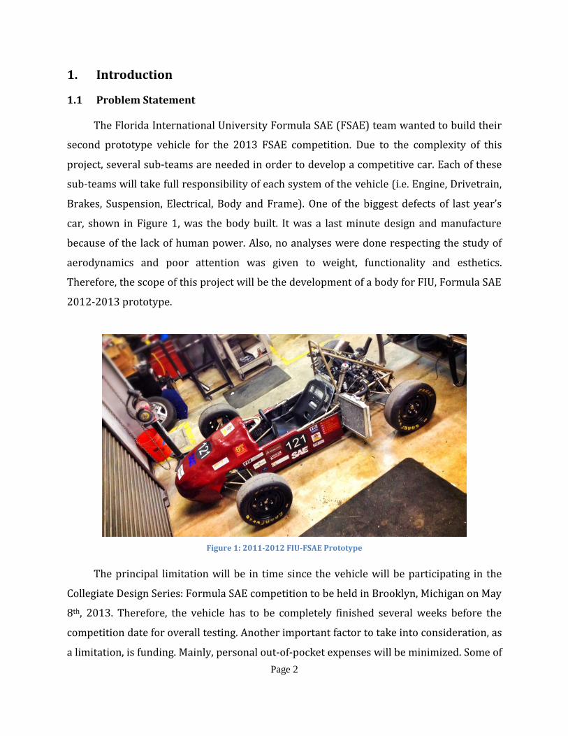
Brakes, Suspension, Electrical, Body and Frame). One of the biggest defects of last year’s
car, shown in Figure 1, was the body built. It was a last minute design and manufacture
because of the lack of human power. Also, no analyses were done respecting the study of
aerodynamics and poor attention was given to weight, functionality and esthetics.
Therefore, the scope of this project will be the development of a body for FIU, Formula SAE
2012-2013 prototype.
Figure 1: 2011-2012 FIU-FSAE Prototype
The principal limitation will be in time since the vehicle will be participating in the
Collegiate Design Series: Formula SAE competition to be held in Brooklyn, Michigan on May
8th, 2013. Therefore, the vehicle has to be completely finished several weeks before the
competition date for overall testing. Another important factor to take into consideration, as
a limitation, is funding. Mainly, personal out-of-pocket expenses will be minimized. Some of
Page 3
the actions to be measured to support this objective include the development of a
sponsorship proposal to approach companies. Some of the benefits for companies include:
exposure, since the vehicle will be competing in a national event; tax deduction, since FIU-
SAE is a non-profit organization with a Tax-ID number; and, the fact that they will be
supporting future engineers with great passion for the automotive industry. Another
source of income will be to attend several fundraising events hosted by FIU-SAE.
1.2 Motivation
Based on the results of last year’s competition, one of the major proposed
improvements for the upcoming prototype was body design. By approaching this task as a
Senior Design Project, it would allow for better and more in-depth analysis that would yield
an optimal design. Our team decided to tackle this project as it involves various advanced
concepts from different fields of engineering, such as: Fluid Dynamics, Structural Analysis,
Mechanics of Materials and Computer Aided Design.
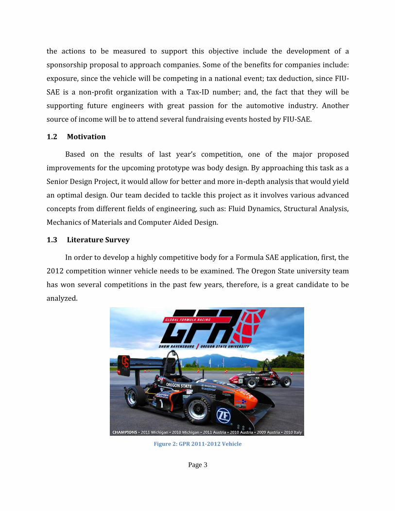
1.3 Literature Survey
In order to develop a highly competitive body for a Formula SAE application, first, the
2012 competition winner vehicle needs to be examined. The Oregon State university team
has won several competitions in the past few years, therefore, is a great candidate to be
analyzed.
Figure 2: GPR 2011-2012 Vehicle
Page 4
Before analyzing its body, a brief explanation about GFR will be provided. “Global
Formula Racing is the first innovative global collaboration of its kind in the history of both
the US-based Formula SAE and EU-based Formula Student programs. The former BA
Racing Team from the Duale Hochschule Baden-Württemberg-Ravensburg (DHBW-R),
Germany, and the Beaver Racing Team from Oregon State University (OSU) have combined
forces to compete as a single entity. The two universities share physical and intellectual
resources to create a highly competitive vehicle worthy of international reputation.” [9]
The GFR team uses a carbon fiber monocoque as its frame and body. The body also
provides a structural rigidity to mount the rest of the systems of the car. This solutions
yield to a tremendous amount of weight savings, but its application is very expensive and
requires a lot of human resources. Due to the complexity of this application and the limited
budget of the FIU-SAE team, the scope of our project will be limited to developing of a
carbon fiber body. More details about this will be explained further in this report.
Several concepts need to be explained before further elaboration on the chosen
design project. First of all, Society of Automotive Engineers (SAE) International is a global
association of more than 128,000 members worldwide. SAE provides a standard in the
aerospace, automotive and commercial-vehicle industries [10]. Moreover, SAE hosts
various student competitions: Baja, Formula, Super Mileage, among others. Secondly,
Formula SAE (FSAE) is a project approached mainly by engineering students in which they
have to develop an open wheel, open cockpit small Formula-style racecar. This racecar, is
to be evaluated for its potential as a production item in an international competition with
over 120 Universities from around the world participating. Students have to research,
design, manufacture, test, develop, and manage production of their school’s prototype. This
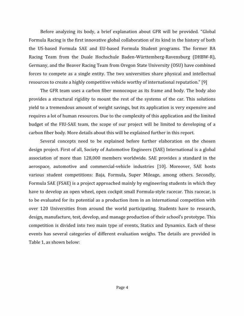
competition is divided into two main type of events, Statics and Dynamics. Each of these
events has several categories of different evaluation weighs. The details are provided in
Table 1, as shown below:
Page 5
Table 1: Competition Events [10]
Type of Event
Category Points
Static Events
Presentation 75
Engineering Design 150
Cost Analysis 100
Dynamic Events
Acceleration 75
Skid-Pad 50
Autocross 150
Fuel Economy 100
Endurance 300
Total Points 1,000
Lastly, FIU-SAE is a group of diverse people with a strong passion for the automotive
industry and is mainly composed by engineering students that represent the Florida
International University Chapter of the Society of Automotive Engineers worldwide. With
their second prototype ever built, FIU-SAE is striving to compete and thrive in the 2013
Formula SAE competition. The main purpose of this organization, is to further develop the
engineering concepts learned in class, and provide a hands-on experience with an actual
object to successfully develop integral engineers for the future.
Page 6
2. Project Formulation
2.1 Project Objectives
To develop a body for the new prototype with the proper studies and analysis, taking
into account several factors to present an optimum body model as a final result. These
factors include, but are not limited to, weight, cost, drag resistance, functionality and
esthetics. The expected product is to be appealing to the eye and it will increase the
performance of the vehicle. Additional objectives include being able to accommodate the
budget while maintaining a highly competitive level to perform well in the competition.
Furthermore, other objectives relates to improvements of past designed bodies. The first
generation of the FIU Formula car was made from fiberglass and its surface was not very
smooth. The new design will reduce the weight of the prototype and as well as the air drag,
taking into consideration the ground effects desired to be implemented in the vehicle as a
crucial factor. Moreover, the new body will be easier to dismantle reducing the service
time.
Another fundamental objective will be participating in the 2013 Formula SAE
competition to be held in Michigan in June 2013. Therefore, not only will this project has to
satisfy the class requirements but also it has to follow and satisfy all of the rules set forth
by SAE International.
3. Design Alternatives
3.1 Overview of Conceptual Designs Developed
The designs that have been considered are thought to tackle the team’s main
concerns, which are wind drag and weight reduction in order to improve overall vehicle
performance. Also, we would like to incorporate some visual attraction with a light but
aerodynamic body design. This will give the vehicle a greater opportunity to score higher
with the judges in the upcoming competitions
Page 7
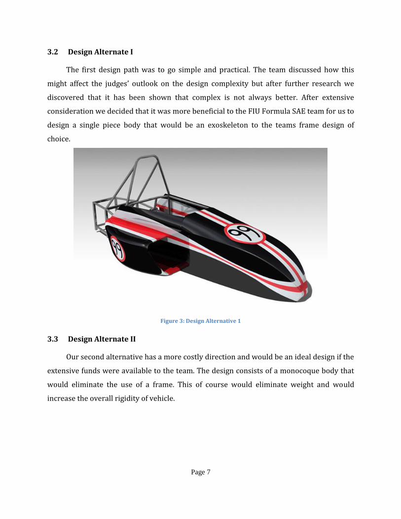
3.2 Design Alternate I
The first design path was to go simple and practical. The team discussed how this
might affect the judges’ outlook on the design complexity but after further research we
discovered that it has been shown that complex is not always better. After extensive
consideration we decided that it was more beneficial to the FIU Formula SAE team for us to
design a single piece body that would be an exoskeleton to the teams frame design of
choice.
Figure 3: Design Alternative 1
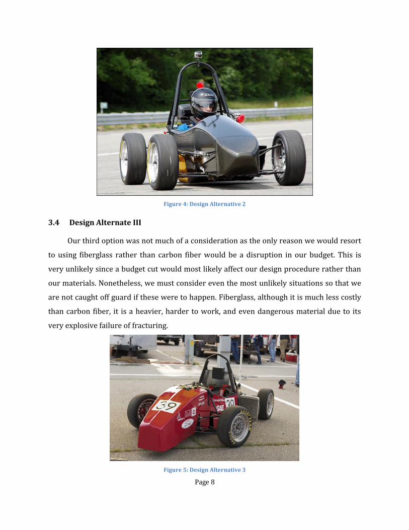
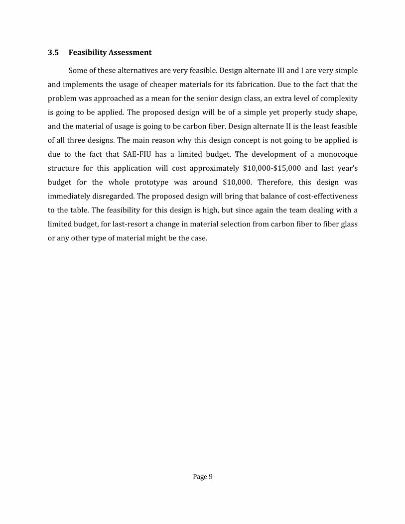
3.3 Design Alternate II
Our second alternative has a more costly direction and would be an ideal design if the
extensive funds were available to the team. The design consists of a monocoque body that
would eliminate the use of a frame. This of course would eliminate weight and would
increase the overall rigidity of vehicle.
Page 8
Figure 4: Design Alternative 2
3.4 Design Alternate III
Our third option was not much of a consideration as the only reason we would resort
to using fiberglass rather than carbon fiber would be a disruption in our budget. This is
very unlikely since a budget cut would most likely affect our design procedure rather than
our materials. Nonetheless, we must consider even the most unlikely situations so that we
are not caught off guard if these were to happen. Fiberglass, although it is much less costly
than carbon fiber, it is a heavier, harder to work, and even dangerous material due to its
very explosive failure of fracturing.
Figure 5: Design Alternative 3
Page 9
3.5 Feasibility Assessment
Some of these alternatives are very feasible. Design alternate III and I are very simple
and implements the usage of cheaper materials for its fabrication. Due to the fact that the
problem was approached as a mean for the senior design class, an extra level of complexity
is going to be applied. The proposed design will be of a simple yet properly study shape,
and the material of usage is going to be carbon fiber. Design alternate II is the least feasible
of all three designs. The main reason why this design concept is not going to be applied is
due to the fact that SAE-FIU has a limited budget. The development of a monocoque
structure for this application will cost approximately $10,000-$15,000 and last year’s
budget for the whole prototype was around $10,000. Therefore, this design was
immediately disregarded. The proposed design will bring that balance of cost-effectiveness
to the table. The feasibility for this design is high, but since again the team dealing with a
limited budget, for last-resort a change in material selection from carbon fiber to fiber glass
or any other type of material might be the case.
Page 10
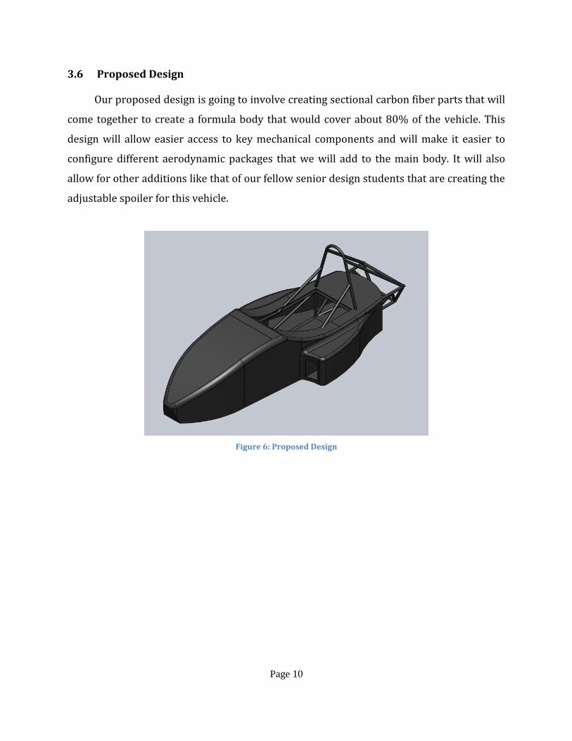
3.6 Proposed Design
Our proposed design is going to involve creating sectional carbon fiber parts that will
come together to create a formula body that would cover about 80% of the vehicle. This
design will allow easier access to key mechanical components and will make it easier to
configure different aerodynamic packages that we will add to the main body. It will also
allow for other additions like that of our fellow senior design students that are creating the
adjustable spoiler for this vehicle.
Figure 6: Proposed Design
Page 11
4. Project Management
4.1 Overview
Since several deliverables have to be turned in during the fall and spring semesters, a
key factor for this project will be planning and organization. Also, if the goals and objective
set forth for this project wants to be accomplished all the requirements from the senior
design class and SAE rules have to be successfully reached in a timely manner. For all of
these reasons a timeline, a breakdown of work into tasks and a breakdown of
responsibilities were developed.
4.2 Breakdown of Work into Specific Tasks
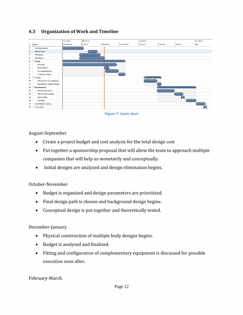
The Gantt chart shown in Figure 7 aids to act as an organizational tool for the team to
have strict deadlines in order to improve the overall organization of the project. The report
submissions for the Fall 2012 semester have been included since they represent important
milestones that the team needs to accomplish. As the semester develops and the dates for
presentations and partial reports for the Spring 2013 semester becomes known, an update
to the Gantt chart needs to be made. Also, the beginning of the project is more research-
oriented with a strong focus on literature survey. As the project develops, it becomes more
of an engineering project and the design of all of the components, as well as testing and
manufacture becomes the first priority. Finally a final report will be rendered and the
vehicle will go to competition.
Page 12
4.3 Organization of Work and Timeline
Figure 7: Gantt chart
August-September
Create a project budget and cost analysis for the total design cost
Put together a sponsorship proposal that will allow the team to approach multiple
companies that will help us monetarily and conceptually.
Initial designs are analyzed and design elimination begins.
October-November
Budget is organized and design parameters are prioritized.
Final design path is chosen and background design begins.
Conceptual design is put together and theoretically tested.
December-January
Physical construction of multiple body designs begins.
Budget is analyzed and finalized.
Fitting and configuration of complementary equipment is discussed for possible
execution soon after.
February-March
Page 13
Final design is chosen and constructed.
Testing, testing and more testing…
Painting and cosmetic touches are added.
April-May
Paperwork is put together and refined.
Presentation and public speaking skills are reviewed in order to prepare for board
presentation.
FSAE competition begins and the car is put to the test against other schools.
4.4 Breakdown of Responsibilities
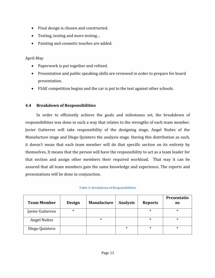
In order to efficiently achieve the goals and milestones set, the breakdown of
responsibilities was done in such a way that relates to the strengths of each team member.
Javier Gutierrez will take responsibility of the designing stage, Angel Nuñez of the
Manufacture stage and Diego Quintero the analysis stage. Having this distribution as such,
it doesn’t mean that each team member will do that specific section on its entirety by
themselves, It means that the person will have the responsibility to act as a team leader for
that section and assign other members their required workload. That way it can be
assured that all team members gain the same knowledge and experience. The reports and
presentations will be done in conjunction.
Table 2: Breakdown of Responsibilities
Team Member Design Manufacture Analysis Reports Presentatio
ns
Javier Gutierrez * * *
Angel Nuñez * * *
Diego Quintero * * *
Page 14
5. Engineering Design and Analysis
5.1 Analytical Analysis
As a design was selected, the body was divided into different sub-components for a
more in-depth approach. These features can be categorized separately as they are
governed by different physical principles. The three main components on the racecar are:
Body, Side Pods and Ground Effects.
5.1.1 Body Analysis
In racecar engineering, the main two reasons for the particular shape of the body is
slice through the air to reduce resistance and to channel the air and create downforce in
specific areas. When used correctly, downforce can directly increase the grip of the tires by
applying a vertical force.
The Bernoulli Principle can explain the main effect during downforce. This states
that a fluid flows around an object at different speeds. The slower moving fluid will create
more pressure than the faster moving fluid on an object. The object will then be forced
toward the faster moving fluid. These same methods are used in airplane wings to create
lift, by creating a pressure drop in the opposite direction. The direct relationship between
curved streamlines and pressure differences was derived by Leonard Euler, which states
[5]:
where R is the radius of curvature, p is the pressure, ρ is the density, and v is the velocity.
This formula shows that higher velocities and tighter curvatures create larger pressure
differentials.
The design of a racecar’s body is designed with this principle in mind. This characteristic is
mostly used by wings or airfoils, which are usually placed above the wheels to increase
grip.
Page 15
5.1.2 Side Pod Analysis
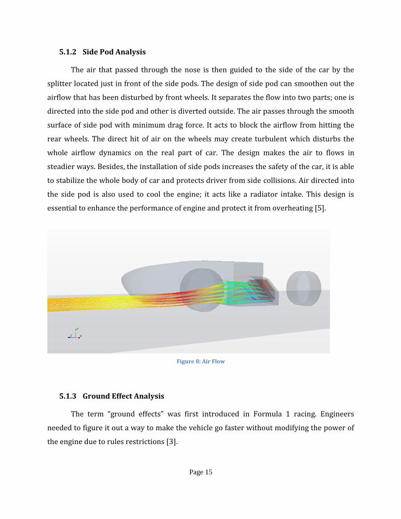
The air that passed through the nose is then guided to the side of the car by the
splitter located just in front of the side pods. The design of side pod can smoothen out the
airflow that has been disturbed by front wheels. It separates the flow into two parts; one is
directed into the side pod and other is diverted outside. The air passes through the smooth
surface of side pod with minimum drag force. It acts to block the airflow from hitting the
rear wheels. The direct hit of air on the wheels may create turbulent which disturbs the
whole airflow dynamics on the real part of car. The design makes the air to flows in
steadier ways. Besides, the installation of side pods increases the safety of the car, it is able
to stabilize the whole body of car and protects driver from side collisions. Air directed into
the side pod is also used to cool the engine; it acts like a radiator intake. This design is
essential to enhance the performance of engine and protect it from overheating [5].
Figure 8: Air Flow
5.1.3 Ground Effect Analysis
The term “ground effects” was first introduced in Formula 1 racing. Engineers
needed to figure it out a way to make the vehicle go faster without modifying the power of
the engine due to rules restrictions [3].
Page 16
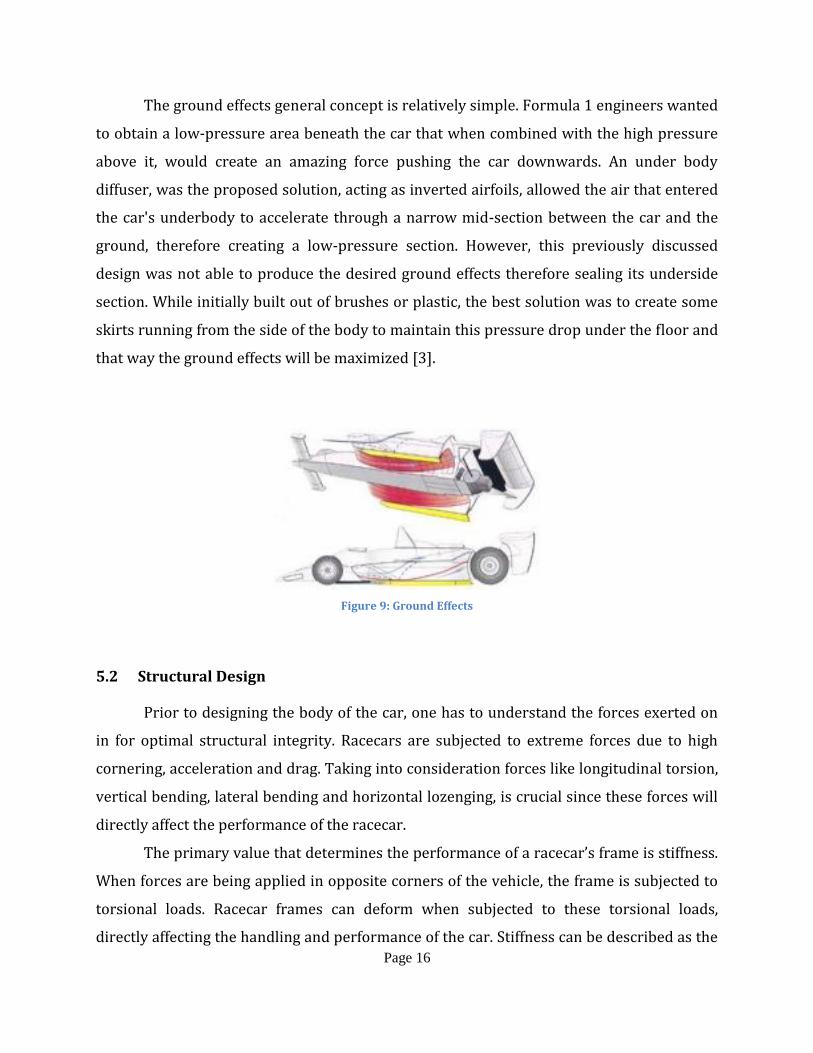
The ground effects general concept is relatively simple. Formula 1 engineers wanted
to obtain a low-pressure area beneath the car that when combined with the high pressure
above it, would create an amazing force pushing the car downwards. An under body
diffuser, was the proposed solution, acting as inverted airfoils, allowed the air that entered
the car's underbody to accelerate through a narrow mid-section between the car and the
ground, therefore creating a low-pressure section. However, this previously discussed
design was not able to produce the desired ground effects therefore sealing its underside
section. While initially built out of brushes or plastic, the best solution was to create some
skirts running from the side of the body to maintain this pressure drop under the floor and
that way the ground effects will be maximized [3].
Figure 9: Ground Effects
5.2 Structural Design
Prior to designing the body of the car, one has to understand the forces exerted on
in for optimal structural integrity. Racecars are subjected to extreme forces due to high
cornering, acceleration and drag. Taking into consideration forces like longitudinal torsion,
vertical bending, lateral bending and horizontal lozenging, is crucial since these forces will
directly affect the performance of the racecar.
The primary value that determines the performance of a racecar’s frame is stiffness.
When forces are being applied in opposite corners of the vehicle, the frame is subjected to
torsional loads. Racecar frames can deform when subjected to these torsional loads,
directly affecting the handling and performance of the car. Stiffness can be described as the
Page 17
resistance of the frame to these torsional forces. Stiffness is usually measured in foot-
pounds per degree, and in a single degree of freedom follows the following governing
equation [5]:
Where F is the force applied to the particular body and δ is the displacement
produced by the force.
Other forces considered such as lateral and vertical bending follow the same
principles. Vertical bending on the frame is usually produced by the weight of the driver
and other components such as the engine, transmission, etc. In the case of lateral bending,
it usually occurs when the vehicle is subjected to forces due to cornering. Other factors that
create lateral bending are road camber and side wind loads. All these factors have to be
considered during the preliminary design stages of the frame, as torsion stiffness is
generally very important, as total cornering traction is a function of lateral weight transfer.
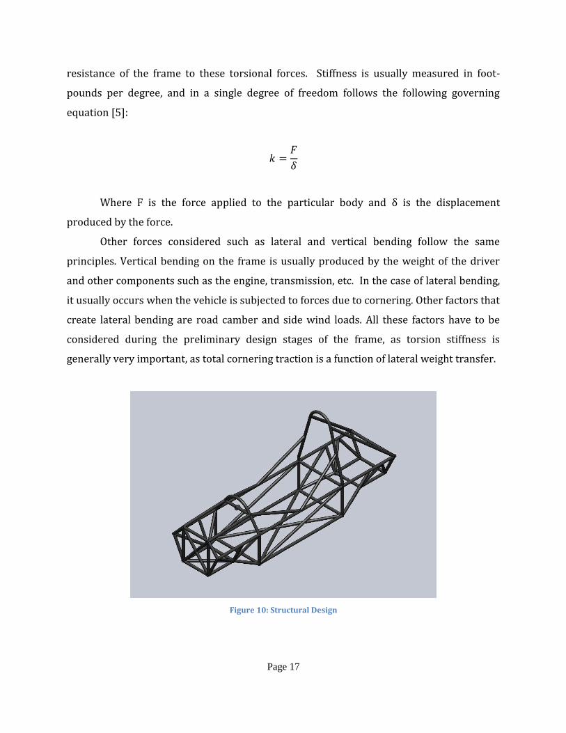
Figure 10: Structural Design
Page 18
The figure above shows the tubular space frame designed for the FSAE body. This
design had to comply with rigorous safety and performance rules stated by SAE. Factors
such as cockpit clearance, overall length and height, and driver dimensions, had to be
considered on top of the torsional loads previously discussed.
5.3 Cost Analysis
The first step towards producing a carbon fiber body is to create a mold for it. The
team decided that using foam and a 3-D printer would produce the best mold needed for
this project. After the first mold is created it is topped with a RTV rubber compound. This
will make a smooth surface where the carbon fiber, resin and hardener will be laid but not
before using a mold release agent on the surface. The next set of materials used includes a
perforated release film that is used to pick up any extra resin left over, with conjunction
with a Nylon bagging film. This film is sealed with sealing tape and then air vacuumed to
allow the resin to cure. A smoothing wax is then applied to the raw product and with some
slight sanding and waxing there will be a glossy and glamorous look that carbon fiber
produces. There are some costs that need to be accounted for the sake of engineering
budgeting but will not be accounted for in our student budget. Some of these cost include
the man-hours used for the project, the machinery used will have to be appraised,
professional advising and consultation expenses. The following chart will show this cost
analysis in more depth.
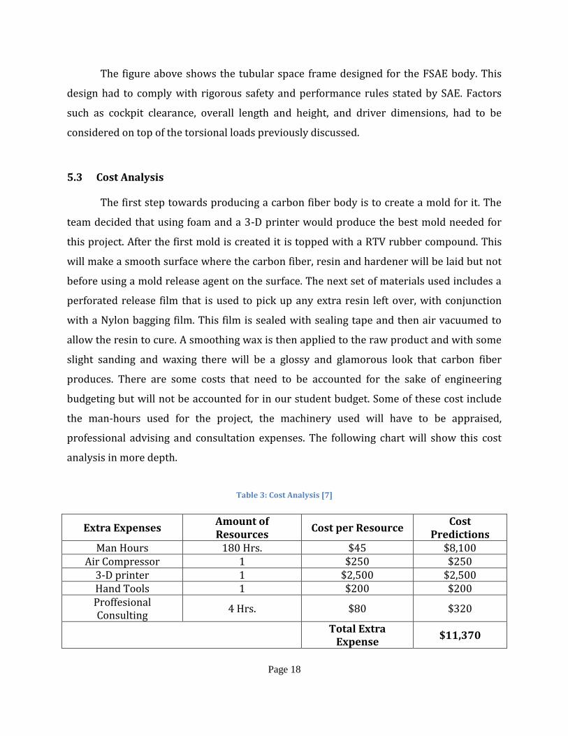
Table 3: Cost Analysis [7]
Extra Expenses Amount of Resources
Cost per Resource Cost
Predictions Man Hours 180 Hrs. $45 $8,100
Air Compressor 1 $250 $250 3-D printer 1 $2,500 $2,500 Hand Tools 1 $200 $200 Proffesional Consulting
4 Hrs. $80 $320
Total Extra
Expense $11,370
Page 19
Table 3 shown above illustrates the extensive extra expensive this project
would obscure if we didn’t have access to the machinery and Professors of FIU.
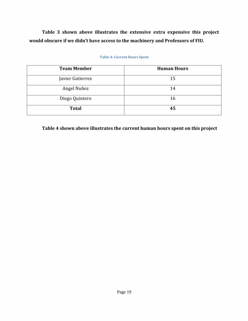
Table 4: Current Hours Spent
Team Member Human Hours
Javier Gutierrez 15
Angel Nuñez 14
Diego Quintero 16
Total 45
Table 4 shown above illustrates the current human hours spent on this project
Page 20
6. Prototype Construction
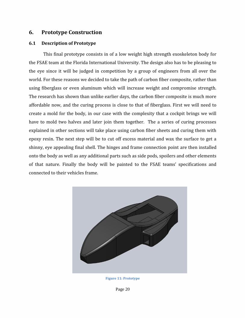
6.1 Description of Prototype
This final prototype consists in of a low weight high strength exoskeleton body for
the FSAE team at the Florida International University. The design also has to be pleasing to
the eye since it will be judged in competition by a group of engineers from all over the
world. For these reasons we decided to take the path of carbon fiber composite, rather than
using fiberglass or even aluminum which will increase weight and compromise strength.
The research has shown than unlike earlier days, the carbon fiber composite is much more
affordable now, and the curing process is close to that of fiberglass. First we will need to
create a mold for the body, in our case with the complexity that a cockpit brings we will
have to mold two halves and later join them together. The a series of curing processes
explained in other sections will take place using carbon fiber sheets and curing them with
epoxy resin. The next step will be to cut off excess material and wax the surface to get a
shinny, eye appealing final shell. The hinges and frame connection point are then installed
onto the body as well as any additional parts such as side pods, spoilers and other elements
of that nature. Finally the body will be painted to the FSAE teams’ specifications and
connected to their vehicles frame.
Figure 11: Prototype
Page 21
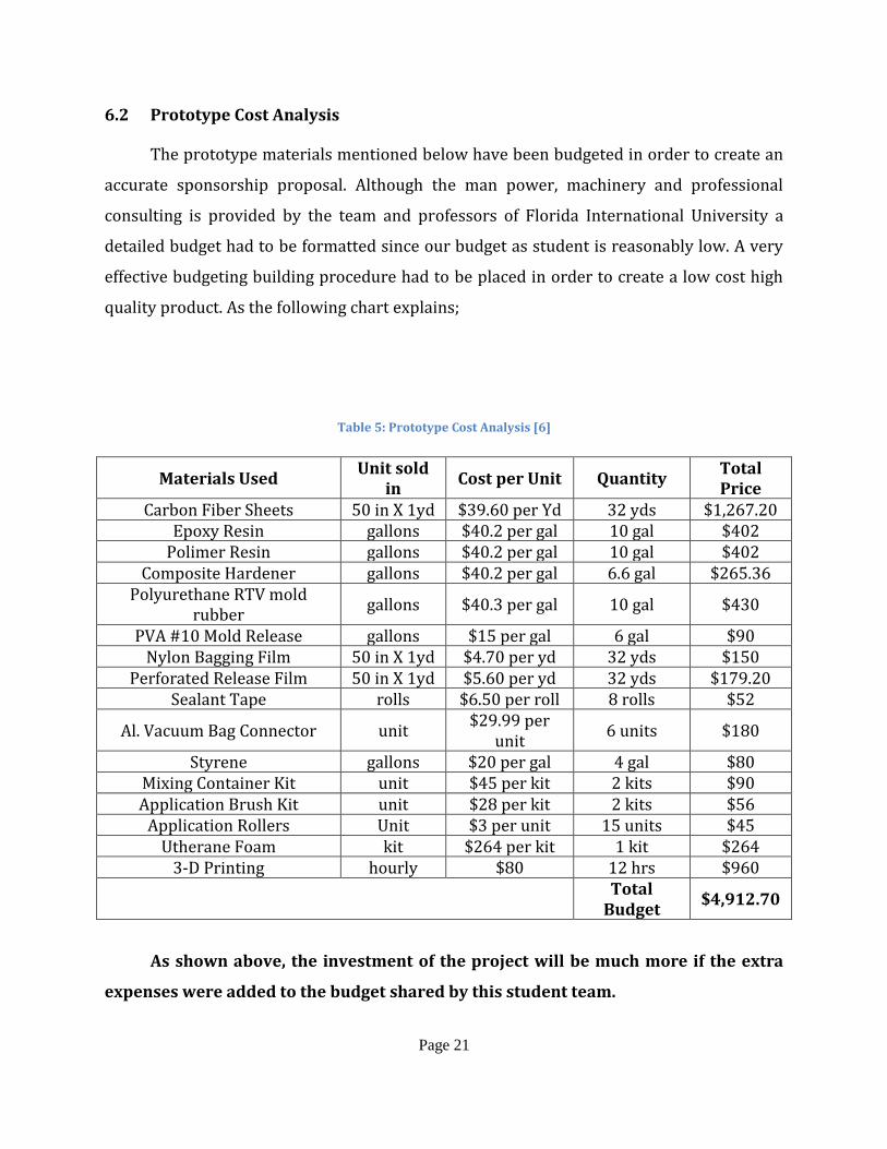
6.2 Prototype Cost Analysis
The prototype materials mentioned below have been budgeted in order to create an
accurate sponsorship proposal. Although the man power, machinery and professional
consulting is provided by the team and professors of Florida International University a
detailed budget had to be formatted since our budget as student is reasonably low. A very
effective budgeting building procedure had to be placed in order to create a low cost high
quality product. As the following chart explains;
Table 5: Prototype Cost Analysis [6]
Materials Used Unit sold
in Cost per Unit Quantity
Total Price
Carbon Fiber Sheets 50 in X 1yd $39.60 per Yd 32 yds $1,267.20 Epoxy Resin gallons $40.2 per gal 10 gal $402
Polimer Resin gallons $40.2 per gal 10 gal $402 Composite Hardener gallons $40.2 per gal 6.6 gal $265.36
Polyurethane RTV mold rubber
gallons $40.3 per gal 10 gal $430
PVA #10 Mold Release gallons $15 per gal 6 gal $90 Nylon Bagging Film 50 in X 1yd $4.70 per yd 32 yds $150
Perforated Release Film 50 in X 1yd $5.60 per yd 32 yds $179.20 Sealant Tape rolls $6.50 per roll 8 rolls $52
Al. Vacuum Bag Connector unit $29.99 per
unit 6 units $180
Styrene gallons $20 per gal 4 gal $80 Mixing Container Kit unit $45 per kit 2 kits $90 Application Brush Kit unit $28 per kit 2 kits $56
Application Rollers Unit $3 per unit 15 units $45 Utherane Foam kit $264 per kit 1 kit $264
3-D Printing hourly $80 12 hrs $960
Total
Budget $4,912.70
As shown above, the investment of the project will be much more if the extra
expenses were added to the budget shared by this student team.
Page 22
7. Testing and Evaluation
7.1 Overview
Testing for this design will first take place in CAD programs such as SolidWorks,
Ansys, etc. There will be major testing components that will be looked at, taking
aerodynamic design testing as our priority since the body will have a frame underneath
and strength testing is not as crucial. Through the SolidWorks FlowExpress feature will be
able to simulate the aerodynamic features of the vehicle at different speed and with
different ground effect components and accessories (Spoiler, ground tunnels, side pods,
etc.). Our final and most important design testing will come from an actual wind tunnel
machine. The physical vehicle will be placed inside this machine and tested a velocity much
higher than the assumed maximum speed of the vehicle to ensure durability and
performance. Before and after every test run there will be a visual inspection of all the
components of the vehicle to check for any signs of structural failure.
Page 23
8. Conclusion
8.1 Conclusion and Discussion
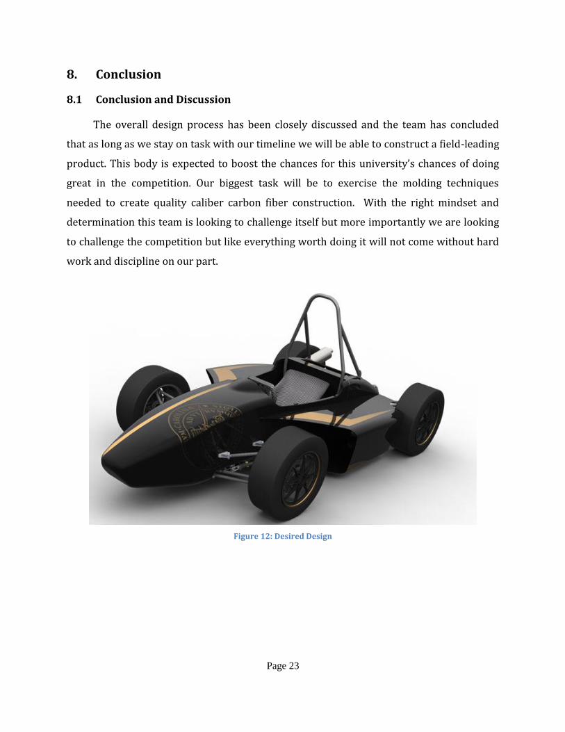
The overall design process has been closely discussed and the team has concluded
that as long as we stay on task with our timeline we will be able to construct a field-leading
product. This body is expected to boost the chances for this university’s chances of doing
great in the competition. Our biggest task will be to exercise the molding techniques
needed to create quality caliber carbon fiber construction. With the right mindset and
determination this team is looking to challenge itself but more importantly we are looking
to challenge the competition but like everything worth doing it will not come without hard
work and discipline on our part.
Figure 12: Desired Design
Page 24
9. References
1) 21st, Sam // Oct, and 2012. "Racecar Engineering | The leading motorsport
technology magazine | F1, Le Mans, Formula Student, Super GT." Racecar
Engineering | The leading motorsport technology magazine | F1, Le Mans, Formula
Student, Super GT. N.p., n.d. Web. 28 Oct. 2012. <http://www.racecar-
engineering.com>.
2) "About | Panther Motorsports." Panther Motorsports | Florida International
University. N.p., n.d. Web. 17 Oct. 2012. <http://www.sae.fiu.edu/about-2>.
3) "autoevolution - automotive news & test drives." autoevolution - automotive news &
test drives. N.p., n.d. Web. 6 Nov. 2012. <http://www.autoevolution.com>.
4) Budynas, Richard G., J. Keith Nisbett, and Joseph Edward Shigley. Shigley's
mechanical engineering design. 9th ed. New York: McGraw-Hill, 2011. Print.
5) Clancy, L. J.. Aerodynamics. New York: Wiley, 1975. Print.
6) "Fiberglass , Epoxy , Composites, Carbon Fiber - U.S. Composites, Inc.." Fiberglass ,
Epoxy , Composites, Carbon Fiber - U.S. Composites, Inc.. N.p., n.d. Web. 1 Nov. 2012.
<http://www.uscomposites.com>.
7) "FSAE.com Forums." FSAE.com. N.p., n.d. Web. 15 Sep. 2012.
<http://www.fsae.com/groupee?s=763607348&cdra=Y>.
8) Hibbeler, Russell C.. Mechanics of materials. 8th ed. Boston: Prentice Hall, 2011.
Print.
9) "History." Global Formula Racing. N.p., n.d. Web. 5 Nov. 2012. <www.global-formula-
racing.com>.
Page 25
10) "SAE Collegiate Design Series: Formula SAE®." Student Central. N.p., n.d. Web. 2 Oct.
2012. <http://students.sae.org/competitions/formulaseries/>.
Page 26
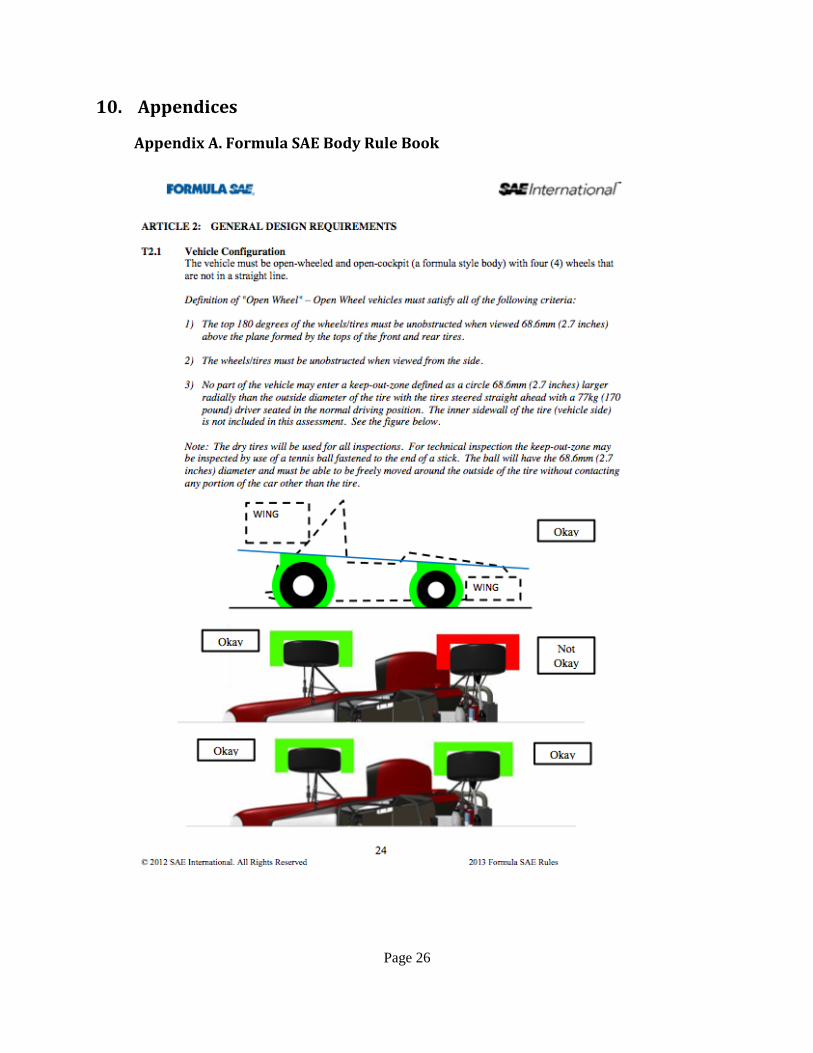
10. Appendices
Appendix A. Formula SAE Body Rule Book
Page 27
Page 28
Page 29
Page 30
Page 31
Page 32
Page 33
Page 34
Page 35
Page 36
Page 37
Page 38
Page 39
Page 40
Page 41
Page 42
Page 43